WO2016147494A1 - 光ファイバケーブルアセンブリ及び測定装置 - Google Patents
光ファイバケーブルアセンブリ及び測定装置 Download PDFInfo
- Publication number
- WO2016147494A1 WO2016147494A1 PCT/JP2015/083759 JP2015083759W WO2016147494A1 WO 2016147494 A1 WO2016147494 A1 WO 2016147494A1 JP 2015083759 W JP2015083759 W JP 2015083759W WO 2016147494 A1 WO2016147494 A1 WO 2016147494A1
- Authority
- WO
- WIPO (PCT)
- Prior art keywords
- optical fiber
- optical
- cable assembly
- connector
- fiber
- Prior art date
- Legal status (The legal status is an assumption and is not a legal conclusion. Google has not performed a legal analysis and makes no representation as to the accuracy of the status listed.)
- Ceased
Links
Images




Classifications
-
- G—PHYSICS
- G02—OPTICS
- G02B—OPTICAL ELEMENTS, SYSTEMS OR APPARATUS
- G02B6/00—Light guides; Structural details of arrangements comprising light guides and other optical elements, e.g. couplings
- G02B6/24—Coupling light guides
- G02B6/36—Mechanical coupling means
- G02B6/38—Mechanical coupling means having fibre to fibre mating means
- G02B6/3807—Dismountable connectors, i.e. comprising plugs
- G02B6/3833—Details of mounting fibres in ferrules; Assembly methods; Manufacture
- G02B6/3834—Means for centering or aligning the light guide within the ferrule
- G02B6/3838—Means for centering or aligning the light guide within the ferrule using grooves for light guides
- G02B6/3839—Means for centering or aligning the light guide within the ferrule using grooves for light guides for a plurality of light guides
-
- G—PHYSICS
- G02—OPTICS
- G02B—OPTICAL ELEMENTS, SYSTEMS OR APPARATUS
- G02B6/00—Light guides; Structural details of arrangements comprising light guides and other optical elements, e.g. couplings
- G02B6/04—Light guides; Structural details of arrangements comprising light guides and other optical elements, e.g. couplings formed by bundles of fibres
- G02B6/06—Light guides; Structural details of arrangements comprising light guides and other optical elements, e.g. couplings formed by bundles of fibres the relative position of the fibres being the same at both ends, e.g. for transporting images
-
- G—PHYSICS
- G02—OPTICS
- G02B—OPTICAL ELEMENTS, SYSTEMS OR APPARATUS
- G02B6/00—Light guides; Structural details of arrangements comprising light guides and other optical elements, e.g. couplings
- G02B6/24—Coupling light guides
- G02B6/36—Mechanical coupling means
- G02B6/38—Mechanical coupling means having fibre to fibre mating means
-
- G—PHYSICS
- G02—OPTICS
- G02B—OPTICAL ELEMENTS, SYSTEMS OR APPARATUS
- G02B6/00—Light guides; Structural details of arrangements comprising light guides and other optical elements, e.g. couplings
- G02B6/24—Coupling light guides
- G02B6/36—Mechanical coupling means
- G02B6/38—Mechanical coupling means having fibre to fibre mating means
- G02B6/3807—Dismountable connectors, i.e. comprising plugs
- G02B6/3833—Details of mounting fibres in ferrules; Assembly methods; Manufacture
- G02B6/3855—Details of mounting fibres in ferrules; Assembly methods; Manufacture characterised by the method of anchoring or fixing the fibre within the ferrule
-
- G—PHYSICS
- G02—OPTICS
- G02B—OPTICAL ELEMENTS, SYSTEMS OR APPARATUS
- G02B6/00—Light guides; Structural details of arrangements comprising light guides and other optical elements, e.g. couplings
- G02B6/24—Coupling light guides
- G02B6/36—Mechanical coupling means
- G02B6/38—Mechanical coupling means having fibre to fibre mating means
- G02B6/3807—Dismountable connectors, i.e. comprising plugs
- G02B6/3833—Details of mounting fibres in ferrules; Assembly methods; Manufacture
- G02B6/3855—Details of mounting fibres in ferrules; Assembly methods; Manufacture characterised by the method of anchoring or fixing the fibre within the ferrule
- G02B6/3862—Details of mounting fibres in ferrules; Assembly methods; Manufacture characterised by the method of anchoring or fixing the fibre within the ferrule radially-compressed, longitudinally-split ferrules consisting of a pair of identical matching halves
-
- G—PHYSICS
- G02—OPTICS
- G02B—OPTICAL ELEMENTS, SYSTEMS OR APPARATUS
- G02B6/00—Light guides; Structural details of arrangements comprising light guides and other optical elements, e.g. couplings
- G02B6/24—Coupling light guides
- G02B6/36—Mechanical coupling means
- G02B6/38—Mechanical coupling means having fibre to fibre mating means
- G02B6/3807—Dismountable connectors, i.e. comprising plugs
- G02B6/3873—Connectors using guide surfaces for aligning ferrule ends, e.g. tubes, sleeves, V-grooves, rods, pins, balls
- G02B6/3882—Connectors using guide surfaces for aligning ferrule ends, e.g. tubes, sleeves, V-grooves, rods, pins, balls using rods, pins or balls to align a pair of ferrule ends
-
- G—PHYSICS
- G02—OPTICS
- G02B—OPTICAL ELEMENTS, SYSTEMS OR APPARATUS
- G02B6/00—Light guides; Structural details of arrangements comprising light guides and other optical elements, e.g. couplings
- G02B6/24—Coupling light guides
- G02B6/36—Mechanical coupling means
- G02B6/38—Mechanical coupling means having fibre to fibre mating means
- G02B6/3807—Dismountable connectors, i.e. comprising plugs
- G02B6/3873—Connectors using guide surfaces for aligning ferrule ends, e.g. tubes, sleeves, V-grooves, rods, pins, balls
- G02B6/3885—Multicore or multichannel optical connectors, i.e. one single ferrule containing more than one fibre, e.g. ribbon type
-
- G—PHYSICS
- G02—OPTICS
- G02B—OPTICAL ELEMENTS, SYSTEMS OR APPARATUS
- G02B6/00—Light guides; Structural details of arrangements comprising light guides and other optical elements, e.g. couplings
- G02B6/24—Coupling light guides
- G02B6/36—Mechanical coupling means
- G02B6/40—Mechanical coupling means having fibre bundle mating means
-
- G—PHYSICS
- G02—OPTICS
- G02B—OPTICAL ELEMENTS, SYSTEMS OR APPARATUS
- G02B6/00—Light guides; Structural details of arrangements comprising light guides and other optical elements, e.g. couplings
- G02B6/24—Coupling light guides
- G02B6/42—Coupling light guides with opto-electronic elements
- G02B6/4201—Packages, e.g. shape, construction, internal or external details
- G02B6/4219—Mechanical fixtures for holding or positioning the elements relative to each other in the couplings; Alignment methods for the elements, e.g. measuring or observing methods especially used therefor
- G02B6/422—Active alignment, i.e. moving the elements in response to the detected degree of coupling or position of the elements
- G02B6/4225—Active alignment, i.e. moving the elements in response to the detected degree of coupling or position of the elements by a direct measurement of the degree of coupling, e.g. the amount of light power coupled to the fibre or the opto-electronic element
-
- G—PHYSICS
- G02—OPTICS
- G02B—OPTICAL ELEMENTS, SYSTEMS OR APPARATUS
- G02B6/00—Light guides; Structural details of arrangements comprising light guides and other optical elements, e.g. couplings
- G02B6/44—Mechanical structures for providing tensile strength and external protection for fibres, e.g. optical transmission cables
-
- G—PHYSICS
- G02—OPTICS
- G02B—OPTICAL ELEMENTS, SYSTEMS OR APPARATUS
- G02B6/00—Light guides; Structural details of arrangements comprising light guides and other optical elements, e.g. couplings
- G02B6/44—Mechanical structures for providing tensile strength and external protection for fibres, e.g. optical transmission cables
- G02B6/4401—Optical cables
- G02B6/4403—Optical cables with ribbon structure
-
- G—PHYSICS
- G02—OPTICS
- G02B—OPTICAL ELEMENTS, SYSTEMS OR APPARATUS
- G02B6/00—Light guides; Structural details of arrangements comprising light guides and other optical elements, e.g. couplings
- G02B6/44—Mechanical structures for providing tensile strength and external protection for fibres, e.g. optical transmission cables
- G02B6/4401—Optical cables
- G02B6/4415—Cables for special applications
-
- G—PHYSICS
- G02—OPTICS
- G02B—OPTICAL ELEMENTS, SYSTEMS OR APPARATUS
- G02B6/00—Light guides; Structural details of arrangements comprising light guides and other optical elements, e.g. couplings
- G02B6/44—Mechanical structures for providing tensile strength and external protection for fibres, e.g. optical transmission cables
- G02B6/4439—Auxiliary devices
- G02B6/444—Systems or boxes with surplus lengths
- G02B6/44528—Patch-cords; Connector arrangements in the system or in the box
-
- G—PHYSICS
- G02—OPTICS
- G02B—OPTICAL ELEMENTS, SYSTEMS OR APPARATUS
- G02B6/00—Light guides; Structural details of arrangements comprising light guides and other optical elements, e.g. couplings
- G02B6/44—Mechanical structures for providing tensile strength and external protection for fibres, e.g. optical transmission cables
- G02B6/4439—Auxiliary devices
- G02B6/4471—Terminating devices ; Cable clamps
- G02B6/44715—Fan-out devices
Definitions
- the present invention relates to an optical fiber cable assembly in which optical connectors are attached to both ends of an optical fiber cable, and a measuring apparatus using the optical fiber cable assembly.
- a bundle fiber that bundles a large number of optical fibers effectively increases the core area, so that a large amount of light can be incident and transmitted, and it is used in various fields such as industrial, medical, and analysis. .
- Bundled fibers are not only those that transmit light in one direction for light transmission or light reception, but also those that transmit and receive light in both directions. Compared with the case of using an independent bundle fiber for light transmission and bundle fiber for light reception, the use of a bundle fiber integrated with transmission / reception has the advantage of simple installation and a small installation space.
- Bundle length is determined according to the application, but a length of about 10 m may be required depending on the application. Such a long bundle fiber is troublesome to handle, and there is a problem that if it is damaged or a failure occurs, all must be replaced.
- Patent Document 1 Has been.
- FIGS. 1A and 1B show an embodiment of an optical signal connecting member described in Patent Document 1.
- the optical signal connecting member includes a first optical fiber sheet 11 and a second optical fiber connecting member.
- 1A and 1B show the configurations of the first optical fiber sheet 11 and the second optical fiber sheet 12, respectively.
- reference numeral 15 denotes an optical fiber.
- the first optical fiber sheet 11 and the second optical fiber sheet 12 are provided with bending portions 11a and 12a, respectively, and the bending directions of the bending portions 11a and 12a are opposite to each other.
- the first optical fiber sheet 11 and the second optical fiber sheet 12 have the second optical fiber sheet 12 on the left side of FIG. 1C, and the first optical fiber sheet 11 is overlaid thereon, respectively.
- Optical fibers 15 protruding from the end of the first connector 13 are inserted into the ferrule holes of the first connector 13 and attached thereto. Visible on the top surface of the first connector 13 is a window 16.
- the second optical fiber sheet 12 comes to the upper side of the first optical fiber sheet 11 and the order of overlap with the left side changes, and the optical fibers 15 protruding from the respective end portions are
- the second connector 14 is attached in the same manner as the first connector 13.
- the window is located in the lower surface side.
- the optical signal connecting member having the above-described configuration is used as a relay cable between two bundle fibers, for example, and a connector connected to each of the first connector 13 and the second connector 14 is attached to the connection end of each bundle fiber.
- the bundle fibers can be separated without increasing the optical connection loss, and it is not necessary to use one long bundle fiber.
- the arrangement of the optical fibers 15 is the same when the front end surface of the connectors 13 and 14 at both ends is observed with the window 16 facing upward.
- the optical signal connecting members described above use the optical fiber sheets 11 and 12, there is a problem that the bending characteristics are directional and difficult to use because they cannot be bent in an arbitrary direction. Since it is difficult to process a fiber into an optical fiber sheet, there is a problem that an optical fiber having a large core cannot be used.
- An object of the present invention is to provide an optical fiber cable assembly suitable for use as a relay cable between bundle fibers, for example, having no directionality in bending characteristics and causing no trouble even with an optical fiber having a large core. It is to provide a measuring apparatus using a cable assembly.
- an optical fiber cable assembly in which optical connectors are attached to both ends of an optical fiber cable, a plurality of optical fiber groups are accommodated in the optical fiber cable, and the optical fibers constituting the optical fiber group are covered. It is possible to identify which optical fiber group belongs to the optical connector, and the optical connector has the same number of optical fiber groups as the number of regions in which insertion holes for inserting and fixing optical fibers one by one are arranged at predetermined intervals. Although the optical fibers of the same optical fiber group are inserted and fixed in the insertion holes of the same region, the arrangement order of the optical fibers in the region of the optical connector at one end is the same as that of the optical fiber in the region of the optical connector at the other end. It is assumed that the arrangement order is not maintained.
- the measuring device for irradiating the measuring object with light and measuring the light from the measuring object is the optical fiber cable assembly according to the present invention, wherein the number of optical fiber groups is two, one of which is transmitted.
- An optical fiber cable assembly that forms a path and the other forms a reception path, and an optical connector that is connected to the optical connector at one end is connected to the optical fiber cable assembly at one end, and the other end is branched into two A first bundle fiber, an optical connector connected to the optical connector at the other end, connected to the optical fiber cable assembly at one end, and a second bundle fiber facing the measurement object at the other end;
- a light source that inputs light to one of the branch ends of one bundle fiber and light from a measurement object that is emitted from the other of the branch ends of the first bundle fiber The more the light-receiving element.
- the present invention there is no directionality in the bending characteristics, which is convenient in that respect, and it is possible to provide an optical fiber cable assembly suitable for use in, for example, a relay cable between bundle fibers.
- the optical fibers constituting the optical fiber group can be easily assembled because it is only necessary to identify the optical fiber group to which the optical fiber group belongs by coating and to be inserted and fixed in an arbitrary insertion hole in a predetermined region without considering the arrangement order. .
- the measuring apparatus of the present invention it becomes easier to handle than a configuration using a single long bundle fiber.
- FIG. 1A is a plan view showing a first optical fiber sheet in a conventional optical signal connecting member.
- FIG. 1B is a plan view showing a second optical fiber sheet in a conventional optical signal connecting member.
- FIG. 1C is a plan view showing a conventional optical signal connecting member.
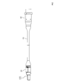
- FIG. 2 is a front view showing an embodiment of the optical fiber cable assembly according to the present invention.
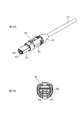
- 3A is a perspective view of the plug in FIG.
- FIG. 3B is a front view of the plug shown in FIG. 3A.
- FIG. 5A is a perspective view of the ferrule in FIGS. 3B and 4B.
- FIG. 5B is a front view of the ferrule shown in FIG. 5A.
- FIG. 6 is a perspective view showing a state in which the optical fiber group is attached to the ferrule.
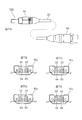
- FIG. 7A is a front view showing an embodiment of the optical fiber cable assembly according to the present invention.
- FIG. 7B is a front view of the ferrule in the plug in FIG. 7A.
- FIG. 7C is a front view of the ferrule in the receptacle in FIG. 7A.
- FIG. 7D is a front view of the ferrule in the plug in FIG. 7A.
- FIG. 7E is a front view of the ferrule in the receptacle in which the arrangement of the optical fiber group is changed from that in FIG. 7C.
- FIG. 8 is a diagram schematically showing a measuring apparatus according to the present invention.
- FIG. 2 shows an embodiment of an optical fiber cable assembly according to the present invention.
- An optical fiber cable assembly 100 has optical connectors attached to both ends of an optical fiber cable 20.
- the optical connector at one end of the fiber cable 20 is a plug 30, and the optical connector at the other end is a receptacle 40.
- 3A, 3B and 4A, 4B show details of the plug 30 and the receptacle 40, respectively.
- 31 indicates a plug body
- 32 indicates a coupling nut
- 33 indicates a boot.
- 4A reference numeral 41 denotes a shell
- 42 denotes a rear insulator
- 43 denotes a boot.
- a ferrule 50 is accommodated in the plug body 31, and the same ferrule 50 is accommodated in the shell 41 as in the plug body 31.
- FIGS. 5A and 5B show the details of the ferrule 50.
- 51 denotes an insertion hole into which an optical fiber is inserted and fixed one by one
- 52 denotes a guide hole.
- Reference numeral 53 denotes a recess in which the end of the optical fiber is accommodated.
- the insertion holes 51 are divided into two regions 54 and 55, and 19 insertion holes 51 are arranged in each region 54 and 55 at predetermined intervals.
- Two guide holes 52 are formed on both sides of the regions 54 and 55. As shown in FIGS. 3A and 3B, guide pins 60 are inserted into the guide holes 52 of the ferrule 50 accommodated in the plug body 31. Be placed. The guide pin 60 protrudes from the front end surface of the ferrule 50 by a predetermined amount.
- two optical fiber groups composed of 19 optical fibers are accommodated in the same number as the regions 54 and 55 of the ferrule 50.
- the optical fibers are accommodated in the outer sheath of the optical fiber cable 20 in an independent state without being bundled and aligned and fixed for each group of optical fibers, and without being bundled and aligned and fixed. ing.
- the optical fibers are coated one by one, and the optical fibers constituting the two optical fiber groups can be identified as to which optical fiber group belongs by the difference in the color of the coating.
- FIG. 6 shows a state in which the optical fibers 21 of the two optical fiber groups taken out from the optical fiber cable 20 are inserted and fixed in the insertion holes 51 of the ferrule 50, and the first optical fiber group 22.
- the optical fiber 21 is inserted and fixed in the insertion hole 51 in the region 54 (see FIG. 5B), and the optical fiber 21 of the second optical fiber group 23 is inserted and fixed in the insertion hole 51 in the region 55 (see FIG. 5B).
- the optical fiber 21 can be inserted and fixed in the insertion hole 51 as long as the optical fibers 21 of the same optical fiber group are inserted and fixed in the insertion hole 51 in the same region, and the arrangement order of the optical fibers 21 is not limited.
- the attachment of the optical fiber 21 of the first optical fiber group 22 and the optical fiber 21 of the second optical fiber group 23 to the ferrule 50 of the plug 30 and the ferrule 50 of the receptacle 40 are the same as described above.
- the optical fiber 21 may be inserted and fixed in the insertion hole 51 in the same region. Therefore, the arrangement order of the optical fibers 21 in the areas 54 and 55 of the ferrule 50 of the plug 30 is not maintained as the arrangement order of the optical fibers 21 in the areas 54 and 55 of the ferrule 50 of the receptacle 40.
- the optical fiber 21 may be simply inserted and fixed in the insertion hole 51 without considering the arrangement order simply by identifying the optical fiber group to which the optical fiber 21 belongs by the color of the coating.
- FIG. 7B-7E show two ways of arranging the first and second optical fiber groups 22 and 23 with respect to the two regions 54 and 55 of the ferrule 50.
- FIG. 7A shows the same manner as FIG. A fiber optic cable assembly 100 is shown.
- 7B and 7D show the ferrule 50 in the plug 30 when the plug 30 is viewed from the distal end side (connection end face side of the optical fiber 21), and
- FIGS. 7C and 7E show the receptacle 40 at the distal end side ( The ferrule 50 in the receptacle 40 when it sees from the connection end surface side of the optical fiber 21 is shown.
- the ferrule within the plug 30 and 50 P in FIG. 7B-7E is set to 50 R ferrule in the receptacle 40.
- FIG. 7B and 7C show a case where the arrangement order of the first optical fiber group 22 and the second optical fiber group 23 in the ferrules 50 P and 50 R is the same as viewed from the connection end face side of the optical fiber 21. , and the words the first optical fiber group 22 in the ferrule 50 R even in the ferrule 50 P is arranged in the area 54, the second optical fiber group 23 are arranged in regions 55.
- FIGS. 7D and 7E show a case where the arrangement order of the first optical fiber group 22 and the second optical fiber group 23 in the ferrules 50 P and 50 R is reversed as viewed from the connection end face side of the optical fiber 21.
- the first optical fiber group 22 in the ferrule 50 P is arranged in the region 54
- the ferrule 50 R is arranged in the region 55.
- the second optical fiber group 23 in the ferrule 50 P is arranged in the region 55
- the ferrule 50 R is arranged in the region 54.
- FIG. 8 shows a preferred example of use of the above-described optical fiber cable assembly 100.
- An optical fiber cable is used as a relay cable between transmission and reception integrated bundle fibers in a measurement apparatus that irradiates light to a measurement object and measures light from the measurement object.
- An example using the assembly 100 is schematically shown.
- the first bundle fiber 200 includes a receptacle 70 as an optical connector connected to the plug 30 of the optical fiber cable assembly 100 at one end, and is connected to the optical fiber cable assembly 100.
- the other end of the first bundle fiber 200 is branched into two.
- the second bundle fiber 300 includes a plug 80 at one end as an optical connector connected to the receptacle 40 of the optical fiber cable assembly 100, and is connected to the optical fiber cable assembly 100.
- the other end of the second bundle fiber 300 is opposed to the measurement object 400.
- 500 indicates a light source
- 600 indicates a light receiving element.
- the optical fiber cable assembly 100 includes the first and second optical fiber groups 22 and 23, and one of the two optical fiber groups 22 and 23 is used as a transmission path (light transmission path). The other is used as a receiving path (light receiving path).
- the light emitted from the light source 500 is incident on the end face of one branching part 210 of the first bundle fiber 200.
- the incident light is transmitted through the first bundle fiber 200, the optical fiber cable 100, and the second bundle fiber 300, is emitted from the end face of the second bundle fiber 300, and is irradiated onto the measurement object 400.
- Light for example, reflected light, scattered light, emitted light, etc.
- Light is incident on the end face of the second bundle fiber 300, and the second bundle fiber 300, the optical fiber cable 100, and the first It is transmitted by one bundle fiber 200 and is emitted from the end face of the other branching portion 220 of the first bundle fiber 200.
- the light emitted from the end face of the branching unit 220 is received by the light receiving element 600, and thereby, the light from the measuring object 400 can be detected and measured.
- the measuring device as shown in FIG. 8 can be used in various fields such as industrial, medical, and analysis.
- the medical field it can be used for measurement of human pulse.
- optical fiber cable assembly 100 is used as the relay cable between the bundle fibers 200 and 300 as described above, it is not necessary to use one long bundle fiber. Since the optical fiber cable assembly 100 and the bundle fibers 200 and 300 are coupled with each other by an optical connector, they can be easily separated, and can be easily handled in that respect, and can be partially replaced even in the case of damage or failure. become.
- the optical fibers 21 in the optical fiber cable 20 are independent one by one as described above, the bending characteristics are not directional and can be bent in an arbitrary direction.
- the optical fibers 21 constituting one optical fiber group are used for the transmission of the same light. There is no need. The amount of light as a whole of the optical fiber group only needs to be ensured, and the number of optical fibers 21 constituting the optical fiber group and the number of insertion holes 51 of the ferrule 50 are appropriately determined.
- the optical fiber 21 to be used preferably has a low transmission loss and a low connection loss.
- H-PCF Hard-Plastic Clad Fiber
- quartz glass core having a quartz glass core and a core diameter as large as 200 ⁇ m. .
- Whether the optical fiber 21 belongs to the first or second optical fiber group 22, 23 can be identified by the difference in the color of the coating of the optical fiber 21, but is not limited to this.
- the color of the coating May be identified by lines and marks written over the entire length on the coating. For example, -Whether there is a line-Whether there is one or two lines-Whether there is a mark can be identified.
- the optical fiber cable assembly 100 includes the plug 30 at one end and the receptacle 40 at the other end.
- the optical fiber cable assembly 100 may be configured to include the plug 30 at both ends, or to include the receptacle 40 at both ends.
- the same plug 30 is provided at both ends or the same receptacle 40 is provided, if the first and second optical fiber groups 22 and 23 are arranged as shown in FIGS. 7B and 7C, the optical fiber cable assembly is directional. There will be no.
- the plug 30 and the receptacle 40 are each provided with one ferrule 50.
- the single ferrule 50 for example, it may be provided with two ferrules divided for each of the areas 54 and 55.
- the number of optical fiber groups in the optical fiber cable 20 is not limited to two, but may be three or more, and is determined according to the usage pattern.
- Ferrule 50 is provided with the same number of regions for connecting optical fiber groups as the number of optical fiber groups.
Landscapes
- Physics & Mathematics (AREA)
- General Physics & Mathematics (AREA)
- Optics & Photonics (AREA)
- Mechanical Coupling Of Light Guides (AREA)
- Optical Fibers, Optical Fiber Cores, And Optical Fiber Bundles (AREA)
Abstract
光ファイバケーブル内には複数の光ファイバ群が収容され、光ファイバ群を構成する光ファイバは被覆によっていずれの光ファイバ群に属するか識別可能とされている。光ファイバケーブルの両端に取り付けられた光コネクタ(プラグ,レセプタクル)は光ファイバが一本ずつ挿入固定される挿入穴が所定の間隔で配列形成された領域を光ファイバ群と同数備え、同じ光ファイバ群の光ファイバは同じ領域の挿入穴に挿入固定されているものの、一端の光コネクタの領域内における光ファイバの配列順序は他端の光コネクタの領域内における光ファイバの配列順序として維持されていない。曲げ特性に方向性がなく、バンドルファイバ間の中継ケーブル等に好適な光ファイバケーブルアセンブリを提供することができる。
Description
この発明は光ファイバケーブルの両端に光コネクタが取り付けられてなる光ファイバケーブルアセンブリ及びその光ファイバケーブルアセンブリを用いる測定装置に関する。
多数の光ファイバを束ねたバンドルファイバは実効的にコア面積が大きくなるので、光を大量に入射させたり、伝送させたりすることができ、工業、医療、分析などの各分野で使用されている。
バンドルファイバには送光用や受光用として単に一方向に光を伝送するもの以外に、両方向に光を伝送する送受一体型のものもある。独立した送光用バンドルファイバと受光用バンドルファイバとを用いる場合に比べ、送受一体型のバンドルファイバを用いれば、設置が簡易で、設置スペースも少なくてすむという利点がある。
バンドルファイバは用途に応じて長さが決定されるが、用途によっては10m程度の長さが必要になる場合がある。このような長いバンドルファイバは取扱いが煩わしく、また破損したり、故障が生じた場合には全てを交換しなければならないといった問題がある。
このような問題を回避するためには、例えばバンドルファイバをいくつかに分け、それらを接続して用いるといったことも考えられるが、バンドルファイバ同士の接続では光ファイバ一本ずつの位置合わせができないので光接続損失の大幅な増大は否めない。
光ファイバ同士を低損失で接続するためには、光ファイバを一本ずつ位置決め可能な光コネクタを用いる必要があり、そのような光コネクタを両端に備えた光信号接続部材が特許文献1に記載されている。
図1A-1Cは特許文献1に記載されている光信号接続部材の一形態を示したものであり、光信号接続部材は図1Cに示したように、第1の光ファイバシート11と第2の光ファイバシート12と、それらの両端に取り付けられた第1のコネクタ13と第2のコネクタ14とによって構成されている。図1A,1Bは第1の光ファイバシート11及び第2の光ファイバシート12の構成をそれぞれ示したものであり、図1A,1B中、15は光ファイバを示す。第1の光ファイバシート11と第2の光ファイバシート12にはそれぞれ湾曲部11a,12aが設けられており、湾曲部11aと12aの湾曲している向きは互いに反対の向きとなっている。
第1の光ファイバシート11と第2の光ファイバシート12は図1Cの左側においては第2の光ファイバシート12を下にして、その上に第1の光ファイバシート11を重ねており、それぞれの端部から突き出した光ファイバ15が第1のコネクタ13のフェルールの孔にそれぞれ挿入されて取り付けられている。第1のコネクタ13の上面に見えているのは窓16である。
一方、図1Cの右側においては第2の光ファイバシート12が第1の光ファイバシート11の上側にきて左側とは重なりの順が変わっており、それぞれの端部から突き出した光ファイバ15が第2のコネクタ14に、第1のコネクタ13と同様に取り付けられている。第2のコネクタ14は窓が下面側に位置している。
上記のような構成を有する光信号接続部材を例えば2つのバンドルファイバ間の中継ケーブルとして用い、各バンドルファイバの接続端に第1のコネクタ13及び第2のコネクタ14とそれぞれ接続されるコネクタを取り付ければ、光接続損失の増大を招くことなく、バンドルファイバを分けることができ、一本の長いバンドルファイバを用いなくても済むようになる。なお、図1Cに示した光信号接続部材では両端のコネクタ13,14を窓16がある面を上にして先端面を観察したときに光ファイバ15の配置が同じになっている。
ところで、上述した光信号接続部材では光ファイバシート11,12を用いているため、曲げ特性に方向性があり、任意の方向に曲げられないことから使いづらいといった問題があり、またコアの大きな光ファイバは光ファイバシートに加工すること自体が難しいため、コアの大きな光ファイバを用いることができないといった問題がある。
この発明の目的は、曲げ特性に方向性がなく、コアの大きな光ファイバでも支障は生じず、例えばバンドルファイバ間の中継ケーブルとして好適な光ファイバケーブルアセンブリを提供することにあり、さらにその光ファイバケーブルアセンブリを用いた測定装置を提供することにある。
この発明によれば、光ファイバケーブルの両端に光コネクタが取り付けられてなる光ファイバケーブルアセンブリにおいて、光ファイバケーブル内には複数の光ファイバ群が収容され、光ファイバ群を構成する光ファイバは被覆によっていずれの光ファイバ群に属するか識別可能とされており、光コネクタは光ファイバが一本ずつ挿入固定される挿入穴が所定の間隔で配列形成された領域を光ファイバ群の数と同数備え、同じ光ファイバ群の光ファイバは同じ領域の挿入穴に挿入固定されているものの、一端の光コネクタの前記領域内における光ファイバの配列順序は他端の光コネクタの前記領域内における光ファイバの配列順序として維持されていないものとされる。
この発明によれば、測定対象に光を照射し、測定対象からの光を測定する測定装置は、この発明による光ファイバケーブルアセンブリであって、光ファイバ群の数が2つとされ、一方が送信経路をなし、他方が受信経路をなすものとされた光ファイバケーブルアセンブリと、前記一端の光コネクタと接続される光コネクタを一端に備えて光ファイバケーブルアセンブリと接続され、他端が2分岐された第1のバンドルファイバと、前記他端の光コネクタと接続される光コネクタを一端に備えて光ファイバケーブルアセンブリと接続され、他端が測定対象と対向される第2のバンドルファイバと、第1のバンドルファイバの分岐端の一方に光を入射する光源と、第1のバンドルファイバの分岐端の他方から出射する測定対象からの光を受光する受光素子とよりなる。
この発明によれば、曲げ特性に方向性がなく、その点で使い勝手がよく、例えばバンドルファイバ間の中継ケーブルなどに用いて好適な光ファイバケーブルアセンブリを提供することができる。
光ファイバ群を構成する光ファイバは被覆によって属する光ファイバ群を識別するだけで配列順序を考慮することなく、所定の領域内の任意の挿入穴に挿入固定すればよいので簡単に組み立てることができる。
また、この発明による測定装置によれば、一本の長いバンドルファイバを用いるような構成に比し、取り扱い易いものとなる。
以下、この発明の実施例を説明する。
図2はこの発明による光ファイバケーブルアセンブリの一実施例を示したものであり、光ファイバケーブルアセンブリ100は光ファイバケーブル20の両端に光コネクタが取り付けられたものとなっており、この例では光ファイバケーブル20の一端の光コネクタはプラグ30とされ、他端の光コネクタはレセプタクル40とされている。
図3A,3B及び図4A,4Bはそれぞれプラグ30及びレセプタクル40の詳細を示したものであり、図3A中、31はプラグボディを示し、32はカップリングナット、33はブーツを示す。また、図4A中、41はシェルを示し、42はリヤインシュレータ、43はブーツを示す。プラグボディ31内にはフェルール50が収容されており、シェル41内にもプラグボディ31内と同じフェルール50が収容されている。
図5A,5Bはフェルール50の詳細を示したものであり、図5A,5B中、51は光ファイバが一本ずつ挿入固定される挿入穴を示し、52はガイド穴を示す。また、53は光ファイバの端末が収容される凹部を示す。挿入穴51はこの例では2つの領域54,55に分かれて形成されており、各領域54,55にはそれぞれ19個の挿入穴51が所定の間隔で配列されて形成されている。
ガイド穴52は領域54,55を挟んで2つ形成されており、プラグボディ31内に収容されるフェルール50のガイド穴52には図3A,3Bに示したようにガイドピン60が挿入されて配置される。ガイドピン60はフェルール50の先端面より所定量突出される。
光ファイバケーブル20内には詳細図示を省略しているが、19本の光ファイバよりなる光ファイバ群がフェルール50の領域54,55の数と同数、2つ収容されている。光ファイバは例えば光ファイバ群毎にまとめられて整列固定されることなく、また複数本ずつまとめられて整列固定されることもなく、それぞれ独立した状態で光ファイバケーブル20の外被内に収容されている。光ファイバは一本ずつ被覆されており、2つの光ファイバ群を構成する光ファイバは被覆の色の違いによっていずれの光ファイバ群に属するか識別可能とされている。
図6は光ファイバケーブル20から取り出された2つの光ファイバ群の光ファイバ21がフェルール50の挿入穴51に挿入固定されて接続された様子を示したものであり、第1の光ファイバ群22の光ファイバ21は領域54(図5B参照)の挿入穴51に挿入固定され、第2の光ファイバ群23の光ファイバ21は領域55(図5B参照)の挿入穴51に挿入固定されている。挿入穴51への光ファイバ21の挿入固定は同じ光ファイバ群の光ファイバ21が同じ領域の挿入穴51に挿入固定されてさえいればよく、光ファイバ21個々の配列順序は問わない。
プラグ30のフェルール50及びレセプタクル40のフェルール50に対する第1の光ファイバ群22の光ファイバ21、第2の光ファイバ群23の光ファイバ21の取り付けは、いずれも上述したように同じ光ファイバ群の光ファイバ21が同じ領域の挿入穴51に挿入固定されていればよい。よって、プラグ30のフェルール50の各領域54,55内における光ファイバ21の配列順序はレセプタクル40のフェルール50の各領域54,55内における光ファイバ21の配列順序として維持されていない。光ファイバ21は被覆の色で属する光ファイバ群を識別するだけで配列順序を考慮することなく、挿入穴51に挿入固定すればよいので組立作業を簡易に行うことができる。
図7B-7Eはフェルール50の2つの領域54,55に対する第1及び第2の光ファイバ群22,23の2通りの配置の仕方を示したものであり、図7Aには図2と同様、光ファイバケーブルアセンブリ100を示している。図7B,図7Dはプラグ30を先端側(光ファイバ21の接続端面側)から見た時のプラグ30内のフェルール50を示したものであり、図7C,図7Eはレセプタクル40を先端側(光ファイバ21の接続端面側)から見た時のレセプタクル40内のフェルール50を示したものである。なお、図7B-7Eにおいてはプラグ30内のフェルールを50Pとし、レセプタクル40内のフェルールを50Rとしている。
図7B,7Cはフェルール50P,50Rにおける第1の光ファイバ群22と第2の光ファイバ群23の配列順序が光ファイバ21の接続端面側から見て一致している場合を示したものであり、即ちフェルール50Pにおいてもフェルール50Rにおいても第1の光ファイバ群22は領域54に配置され、第2の光ファイバ群23は領域55に配置されている。
一方、図7D,7Eはフェルール50P,50Rにおける第1の光ファイバ群22と第2の光ファイバ群23の配列順序が光ファイバ21の接続端面側から見て逆になっている場合を示したものであり、第1の光ファイバ群22はフェルール50Pにおいては領域54に配置され、フェルール50Rにおいては領域55に配置されている。従って、第2の光ファイバ群23はフェルール50Pにおいては領域55に配置され、フェルール50Rにおいては領域54に配置されている。
第1及び第2の光ファイバ群22,23のフェルール50P,50Rに対する配置の仕方(配列順序)はこのように2通りあり、光ファイバケーブルアセンブリ100の使用形態(接続形態)に応じて選択される。
図8は上述した光ファイバケーブルアセンブリ100の好適な使用例として、測定対象に光を照射し、測定対象からの光を測定する測定装置において送受一体型のバンドルファイバ間の中継ケーブルとして光ファイバケーブルアセンブリ100を用いた例を模式的に示したものである。
第1のバンドルファイバ200は光ファイバケーブルアセンブリ100のプラグ30と接続される光コネクタとしてレセプタクル70を一端に備えており、光ファイバケーブルアセンブリ100と接続されている。第1のバンドルファイバ200の他端は2つに分岐されている。第2のバンドルファイバ300は光ファイバケーブルアセンブリ100のレセプタクル40と接続される光コネクタとしてプラグ80を一端に備えており、光ファイバケーブルアセンブリ100と接続されている。第2のバンドルファイバ300の他端は測定対象400と対向されている。
図8中、500は光源を示し、600は受光素子を示す。光ファイバケーブルアセンブリ100は前述したように第1及び第2の2つの光ファイバ群22,23を備えており、2つの光ファイバ群22,23の一方が送信経路(送光経路)として使用され、他方が受信経路(受光経路)として使用される。
光源500から出射された光は第1のバンドルファイバ200の一方の分岐部210の端面に入射される。入射された光は第1のバンドルファイバ200、光ファイバケーブル100及び第2のバンドルファイバ300によって伝送されて第2のバンドルファイバ300の端面から出射し、測定対象400に照射される。
光の照射により測定対象400から得られる光(例えば、反射光や散乱光、放出光等)は第2のバンドルファイバ300の端面に入射し、第2のバンドルファイバ300、光ファイバケーブル100及び第1のバンドルファイバ200により伝送されて第1のバンドルファイバ200の他方の分岐部220の端面から出射する。分岐部220の端面から出射した光は受光素子600によって受光され、これにより測定対象400からの光を検出し、測定することができる。
この図8に示したような測定装置は工業、医療、分析などの各分野で使用することができる。例えば、医療の分野で言えば、人体の脈派の測定などに用いることができる。
バンドルファイバ200と300の間に上述したように中継ケーブルとして光ファイバケーブルアセンブリ100を用いれば、一本の長いバンドルファイバを用いなくても済むようになる。光ファイバケーブルアセンブリ100とバンドルファイバ200,300は光コネクタによって結合されているため、分離も容易であり、その点で取り扱い易く、破損したり、故障が生じた場合でも部分的な交換で済むようになる。
また、光ファイバケーブル20内の光ファイバ21は前述したように一本ずつ独立しているため、曲げ特性に方向性はなく、任意の方向に曲げられるため、使い勝手のよいものとなる。
以上、この発明の実施例について説明したが、光ファイバケーブルアセンブリ100においては一つの光ファイバ群を構成する光ファイバ21は同じ光の伝送に用いられるため、光ファイバ21個々の配列順序は考慮する必要がない。光ファイバ群全体としての光量が確保されればよく、光ファイバ群を構成する光ファイバ21の数、フェルール50の挿入穴51の数は適宜、決定される。
用いる光ファイバ21は伝送損失が少なく、接続損失も少ないものが望ましく、その点で石英ガラスのコアを有し、コア直径が200μmと大きいH-PCF(Hard-Plastic Clad Fiber)を用いるのが好ましい。
光ファイバ21が第1及び第2の光ファイバ群22,23のいずれに属するかは光ファイバ21の被覆の色の違いによって識別できるものとなっているが、これに限らず、例えば被覆の色は同じにして被覆上に全長に渡って記したラインやマークによって識別するようにしてもよい。例えば、
・ラインが有るか否か
・ラインが1本か2本か
・マークが有るか否か
等によって識別することができる。
・ラインが有るか否か
・ラインが1本か2本か
・マークが有るか否か
等によって識別することができる。
上述した例では光ファイバケーブルアセンブリ100は一端にプラグ30を備え、他端にレセプタクル40を備えているが、プラグ30を両端に備える構成やレセプタクル40を両端に備える構成としてもよい。両端に同じプラグ30を備える場合あるいは同じレセプタクル40を備える場合、図7B,7Cに示したような第1及び第2の光ファイバ群22,23の配列とすれば、光ファイバケーブルアセンブリは方向性のないものとなる。
一方、図2に示した構成を採用し、第1及び第2の光ファイバ群22,23の配列を図7D,7Eに示した配列とすれば、図8に示した使用形態において例えば光ファイバケーブルアセンブリ100をなしとしたバンドルファイバ200と300の直接接続(短絡接続)も可能とすることができる。
プラグ30及びレセプタクル40はそれぞれフェルール50を1つ備えるものとなっているが、単一のフェルール50ではなく、例えば領域54,55毎に分かれた2つのフェルールを備えるものとしてもよい。
光ファイバケーブル20内の光ファイバ群の数は2つに限定されるものではなく、3つ以上であってもよく、使用形態に応じて決定される。フェルール50には光ファイバ群を接続する領域が光ファイバ群の数と同数、設けられる。
Claims (7)
- 光ファイバケーブルの両端に光コネクタが取り付けられてなる光ファイバケーブルアセンブリであり、
前記光ファイバケーブル内には複数の光ファイバ群が収容され、
前記光ファイバ群を構成する光ファイバは被覆によっていずれの前記光ファイバ群に属するか識別可能とされており、
前記光コネクタは前記光ファイバが一本ずつ挿入固定される挿入穴が所定の間隔で配列形成された領域を前記光ファイバ群の数と同数備え、
同じ光ファイバ群の前記光ファイバは同じ領域の前記挿入穴に挿入固定されているものの、一端の前記光コネクタの前記領域内における前記光ファイバの配列順序は他端の前記光コネクタの前記領域内における前記光ファイバの配列順序として維持されていない。 - 請求項1の光ファイバケーブルアセンブリにおいて、
前記光コネクタを前記光ファイバの接続端面側から見て前記複数の光ファイバ群の配列順序は前記一端の光コネクタと前記他端の光コネクタとで一致している。 - 請求項1又は2の光ファイバケーブルアセンブリにおいて、
前記領域は前記光コネクタが具備する単一のフェルールに設けられている。 - 請求項1乃至3のいずれかの光ファイバケーブルアセンブリにおいて、
前記光ファイバはH-PCFである。 - 請求項1乃至4のいずれかの光ファイバケーブルアセンブリにおいて、
前記光ファイバは被覆の色によっていずれの前記光ファイバ群に属するか識別可能とされている。 - 請求項1乃至5のいずれかの光ファイバケーブルアセンブリにおいて、
前記光ファイバ群の数は2つとされ、一方が送信経路をなし、他方が受信経路をなす。 - 測定対象に光を照射し、前記測定対象からの光を測定する測定装置であり、
請求項6記載の光ファイバケーブルアセンブリと、
前記一端の光コネクタと接続される光コネクタを一端に備えて前記光ファイバケーブルアセンブリと接続され、他端が2分岐された第1のバンドルファイバと、
前記他端の光コネクタと接続される光コネクタを一端に備えて前記光ファイバケーブルアセンブリと接続され、他端が前記測定対象と対向される第2のバンドルファイバと、
前記第1のバンドルファイバの分岐端の一方に光を入射する光源と、
前記第1のバンドルファイバの分岐端の他方から出射する前記測定対象からの光を受光する受光素子とよりなる。
Priority Applications (2)
| Application Number | Priority Date | Filing Date | Title |
|---|---|---|---|
| CN201580076182.3A CN107250864B (zh) | 2015-03-18 | 2015-12-01 | 光纤电缆组件及测定装置 |
| US15/532,742 US10754090B2 (en) | 2015-03-18 | 2015-12-01 | Optical fiber cable assembly and measurement device |
Applications Claiming Priority (2)
| Application Number | Priority Date | Filing Date | Title |
|---|---|---|---|
| JP2015054809A JP5925930B1 (ja) | 2015-03-18 | 2015-03-18 | 光ファイバケーブルアセンブリ及び測定装置 |
| JP2015-054809 | 2015-03-18 |
Publications (1)
| Publication Number | Publication Date |
|---|---|
| WO2016147494A1 true WO2016147494A1 (ja) | 2016-09-22 |
Family
ID=56069531
Family Applications (1)
| Application Number | Title | Priority Date | Filing Date |
|---|---|---|---|
| PCT/JP2015/083759 Ceased WO2016147494A1 (ja) | 2015-03-18 | 2015-12-01 | 光ファイバケーブルアセンブリ及び測定装置 |
Country Status (4)
| Country | Link |
|---|---|
| US (1) | US10754090B2 (ja) |
| JP (1) | JP5925930B1 (ja) |
| CN (1) | CN107250864B (ja) |
| WO (1) | WO2016147494A1 (ja) |
Families Citing this family (4)
| Publication number | Priority date | Publication date | Assignee | Title |
|---|---|---|---|---|
| USD874402S1 (en) * | 2018-06-08 | 2020-02-04 | J.S.T. Corporation | Electrical connector |
| JP1626347S (ja) * | 2018-06-20 | 2019-03-11 | ||
| JP1680801S (ja) * | 2020-08-26 | 2021-03-08 | ||
| CN115632709B (zh) * | 2022-11-14 | 2026-06-02 | 江苏苏美达机电有限公司 | 光缆组件及光缆测试方法 |
Citations (3)
| Publication number | Priority date | Publication date | Assignee | Title |
|---|---|---|---|---|
| JP2001264597A (ja) * | 2000-03-15 | 2001-09-26 | Fujikura Ltd | 光ファイバ心線 |
| JP2003202473A (ja) * | 2001-12-28 | 2003-07-18 | Fujikura Ltd | コネクタ付き光ファイバコード及びコネクタ付き光ファイバケーブル |
| WO2013186879A1 (ja) * | 2012-06-13 | 2013-12-19 | 株式会社シンクロン | 膜厚測定装置及び成膜装置 |
Family Cites Families (17)
| Publication number | Priority date | Publication date | Assignee | Title |
|---|---|---|---|---|
| FR2588670B1 (fr) * | 1985-10-16 | 1987-12-11 | Lignes Telegraph Telephon | Tete d'eclatement d'un cable a fibres optiques |
| US6351590B1 (en) * | 1999-06-30 | 2002-02-26 | Lucent Technologies Inc. | Optical harness with optical connector and cross-connect method |
| US6442318B1 (en) * | 1999-11-23 | 2002-08-27 | Schott Fiber Optics, Inc. | Prefabricated optical fiber ribbon cable for connectorizing with a terminal connector and methods of connectorizing and fabricating the same |
| US6464404B1 (en) * | 2000-06-19 | 2002-10-15 | Schott Fiber Optics, Inc. | Optical fiber rearrangement method and device |
| US6678449B2 (en) * | 2001-07-10 | 2004-01-13 | Alcatel | Visibly distinguishable colored optical fiber ribbons |
| US20030053772A1 (en) * | 2001-09-18 | 2003-03-20 | Mitsubishi Cable Industries, Ltd. | Optical fiber sheet, method of manufacturing the same, and optical fiber interconnector |
| US6769811B2 (en) * | 2002-09-03 | 2004-08-03 | Stratos International, Inc. | Multi-fiber optic device |
| US6707972B1 (en) * | 2002-12-10 | 2004-03-16 | Westek Electronics, Inc. | Optical multi-connector test cable |
| US7266274B2 (en) | 2004-11-03 | 2007-09-04 | Corning Cable Systems Llc | Pre-connectorized fiber optic distribution cable having overmolded access location |
| CN102681119B (zh) | 2008-06-30 | 2015-01-28 | 日本电信电话株式会社 | 光纤缆线以及光纤带 |
| US7756371B1 (en) | 2009-01-30 | 2010-07-13 | Corning Cable Systems Llc | Optical fiber interconnection devices and systems using same |
| JP5497544B2 (ja) | 2010-06-09 | 2014-05-21 | 住友電気工業株式会社 | コネクタ付集合光ケーブル |
| JP5794135B2 (ja) * | 2011-12-20 | 2015-10-14 | 日立金属株式会社 | 光モジュール |
| WO2013099753A1 (ja) | 2011-12-28 | 2013-07-04 | 住友電気工業株式会社 | 光モジュール |
| US9442265B2 (en) * | 2012-09-18 | 2016-09-13 | Clearfield, Inc. | Optical fiber management system |
| JP2014122959A (ja) | 2012-12-20 | 2014-07-03 | Mitsubishi Cable Ind Ltd | 光信号接続部材 |
| US9568691B2 (en) * | 2013-06-12 | 2017-02-14 | Corning Optical Communications LLC | Durable optical fiber and connector assembly |
-
2015
- 2015-03-18 JP JP2015054809A patent/JP5925930B1/ja active Active
- 2015-12-01 CN CN201580076182.3A patent/CN107250864B/zh active Active
- 2015-12-01 US US15/532,742 patent/US10754090B2/en active Active
- 2015-12-01 WO PCT/JP2015/083759 patent/WO2016147494A1/ja not_active Ceased
Patent Citations (3)
| Publication number | Priority date | Publication date | Assignee | Title |
|---|---|---|---|---|
| JP2001264597A (ja) * | 2000-03-15 | 2001-09-26 | Fujikura Ltd | 光ファイバ心線 |
| JP2003202473A (ja) * | 2001-12-28 | 2003-07-18 | Fujikura Ltd | コネクタ付き光ファイバコード及びコネクタ付き光ファイバケーブル |
| WO2013186879A1 (ja) * | 2012-06-13 | 2013-12-19 | 株式会社シンクロン | 膜厚測定装置及び成膜装置 |
Also Published As
| Publication number | Publication date |
|---|---|
| US10754090B2 (en) | 2020-08-25 |
| JP5925930B1 (ja) | 2016-05-25 |
| CN107250864B (zh) | 2020-05-19 |
| US20170357050A1 (en) | 2017-12-14 |
| CN107250864A (zh) | 2017-10-13 |
| JP2016176975A (ja) | 2016-10-06 |
Similar Documents
| Publication | Publication Date | Title |
|---|---|---|
| US8314603B2 (en) | Network cable with tracer optical waveguide | |
| CN107995953B (zh) | 包括光纤对准装置的光纤连接系统 | |
| CN110178063B (zh) | 光纤保持部件、光连接器及光耦合构造 | |
| US10317638B2 (en) | Flexible optical circuit, cassettes, and methods | |
| CN102282492B (zh) | 混合式连接器 | |
| US20180172925A1 (en) | Traceable end point cable assembly having a tracing waveguide | |
| US10101545B2 (en) | Traceable cable assembly and connector | |
| JP6157457B2 (ja) | 多心光コネクタ | |
| EP3433652B1 (en) | Optical connector with photodetector, adaptor for optical connector, and system | |
| WO2008023544A1 (en) | Light path converting member and connector for light path converted light | |
| JP5925930B1 (ja) | 光ファイバケーブルアセンブリ及び測定装置 | |
| JP2015200789A (ja) | 光接続構造 | |
| CN102472877A (zh) | 带连接器的集束光缆 | |
| JP6684461B2 (ja) | 光可視化フィルタ及びそれを用いた通信光可視化装置 | |
| JP2021511545A (ja) | 光トレース可能なパッチコード | |
| CN109698423B (zh) | 线缆端部识别器及使用该对应识别器的线缆组件 | |
| US9389380B2 (en) | Optical fiber assembly, optical probe, and method for manufacturing optical fiber assembly | |
| JP2021051242A (ja) | 光ファイババンドルの端部構造 | |
| US20070127871A1 (en) | Boot for MT connector | |
| KR102842525B1 (ko) | 광섬유 연결장치 | |
| JP4291815B2 (ja) | 多心光コネクタ付き分岐心線および光回路基板 | |
| US11555967B2 (en) | Fiber connection structure provided with optical connector, module, and assembly | |
| JP4597872B2 (ja) | 光接続箱 | |
| JPWO2024122265A5 (ja) | ||
| JP2015191121A (ja) | 接続装置、計算機システム及びその接続方法 |
Legal Events
| Date | Code | Title | Description |
|---|---|---|---|
| 121 | Ep: the epo has been informed by wipo that ep was designated in this application |
Ref document number: 15885586 Country of ref document: EP Kind code of ref document: A1 |
|
| WWE | Wipo information: entry into national phase |
Ref document number: 15532742 Country of ref document: US |
|
| NENP | Non-entry into the national phase |
Ref country code: DE |
|
| 122 | Ep: pct application non-entry in european phase |
Ref document number: 15885586 Country of ref document: EP Kind code of ref document: A1 |