WO2016143977A1 - 리튬이온 이차전지용 바인더 및 이를 갖는 리튬이온 이차 전지 - Google Patents
리튬이온 이차전지용 바인더 및 이를 갖는 리튬이온 이차 전지 Download PDFInfo
- Publication number
- WO2016143977A1 WO2016143977A1 PCT/KR2015/012128 KR2015012128W WO2016143977A1 WO 2016143977 A1 WO2016143977 A1 WO 2016143977A1 KR 2015012128 W KR2015012128 W KR 2015012128W WO 2016143977 A1 WO2016143977 A1 WO 2016143977A1
- Authority
- WO
- WIPO (PCT)
- Prior art keywords
- binder
- secondary battery
- lithium ion
- ion secondary
- negative electrode
- Prior art date
- Legal status (The legal status is an assumption and is not a legal conclusion. Google has not performed a legal analysis and makes no representation as to the accuracy of the status listed.)
- Ceased
Links
Images


Classifications
-
- H—ELECTRICITY
- H01—ELECTRIC ELEMENTS
- H01M—PROCESSES OR MEANS, e.g. BATTERIES, FOR THE DIRECT CONVERSION OF CHEMICAL ENERGY INTO ELECTRICAL ENERGY
- H01M4/00—Electrodes
- H01M4/02—Electrodes composed of, or comprising, active material
- H01M4/62—Selection of inactive substances as ingredients for active masses, e.g. binders, fillers
- H01M4/621—Binders
- H01M4/622—Binders being polymers
-
- H—ELECTRICITY
- H01—ELECTRIC ELEMENTS
- H01M—PROCESSES OR MEANS, e.g. BATTERIES, FOR THE DIRECT CONVERSION OF CHEMICAL ENERGY INTO ELECTRICAL ENERGY
- H01M4/00—Electrodes
- H01M4/02—Electrodes composed of, or comprising, active material
- H01M4/62—Selection of inactive substances as ingredients for active masses, e.g. binders, fillers
-
- H—ELECTRICITY
- H01—ELECTRIC ELEMENTS
- H01M—PROCESSES OR MEANS, e.g. BATTERIES, FOR THE DIRECT CONVERSION OF CHEMICAL ENERGY INTO ELECTRICAL ENERGY
- H01M10/00—Secondary cells; Manufacture thereof
- H01M10/05—Accumulators with non-aqueous electrolyte
- H01M10/052—Li-accumulators
- H01M10/0525—Rocking-chair batteries, i.e. batteries with lithium insertion or intercalation in both electrodes; Lithium-ion batteries
-
- Y—GENERAL TAGGING OF NEW TECHNOLOGICAL DEVELOPMENTS; GENERAL TAGGING OF CROSS-SECTIONAL TECHNOLOGIES SPANNING OVER SEVERAL SECTIONS OF THE IPC; TECHNICAL SUBJECTS COVERED BY FORMER USPC CROSS-REFERENCE ART COLLECTIONS [XRACs] AND DIGESTS
- Y02—TECHNOLOGIES OR APPLICATIONS FOR MITIGATION OR ADAPTATION AGAINST CLIMATE CHANGE
- Y02E—REDUCTION OF GREENHOUSE GAS [GHG] EMISSIONS, RELATED TO ENERGY GENERATION, TRANSMISSION OR DISTRIBUTION
- Y02E60/00—Enabling technologies; Technologies with a potential or indirect contribution to GHG emissions mitigation
- Y02E60/10—Energy storage using batteries
Definitions
- the present invention relates to a binder for a lithium ion secondary battery and a lithium ion secondary battery having the same.
- the lithium ion secondary battery is one of energy storage devices for storing energy.
- Lithium-ion secondary batteries have a higher energy density than nickel cadmium batteries, have no memory effect, are environmentally friendly, have a long life cycle, can output high voltage, and above all, they can be miniaturized. Recently, it is widely used in small portable electronic products such as mobile phones, tablet PCs and camcorders.
- Conventional lithium ion secondary batteries include a positive electrode, a negative electrode, a separator and an electrolyte as main components.
- the positive electrode of a conventional lithium ion secondary battery includes lithium oxide, the negative electrode contains a carbon compound, such as graphite that can store the lithium ion, the separator prevents the positive electrode and the negative electrode directly contact, the electrolyte solution in the positive electrode and the negative electrode It acts as a vehicle to allow lithium ions to move.
- a carbon compound such as graphite that can store the lithium ion
- the separator prevents the positive electrode and the negative electrode directly contact, the electrolyte solution in the positive electrode and the negative electrode It acts as a vehicle to allow lithium ions to move.
- the negative electrode material of the lithium ion secondary battery is changed from a carbon material to a silicon material, the reversible capacity and energy density of the lithium ion secondary battery having the silicon negative electrode can be increased, whereas the lithium ion secondary battery is charged and discharged.
- the volume of the silicon-based material is expanded by about 400% or more, the binder and the active material of the silicon-based material are detached from the negative electrode, and thus the life of the lithium ion secondary battery is greatly reduced.
- Korean Patent Publication No. 2007-0110569 published on November 20, 2007, "Physically blended polyurethane as a binder
- An electrode mixture containing acrylic acid and a lithium secondary battery based thereon disclose a binder in which polyurethane is physically mixed with polyacrylic acid (PAA).
- PAA polyacrylic acid
- a negative electrode mixture is prepared using a binder having polyacrylic acid (PAA), a silicon active material, a conductive material, and a solvent as a binder of a silicon negative electrode of a lithium ion secondary battery, a solid containing a silicon active material, a binder, and a conductive material in a solvent
- PAA polyacrylic acid
- the present invention provides a combination of abundant elasticity that can respond to the volume expansion of the silicon crab material, stiffness and cohesion to cope with external stress, in order to prevent a decrease in life due to volume expansion and contraction caused by using the silicon-based material during charge and discharge
- a binder for a lithium ion secondary battery having and a lithium ion secondary battery having the same are provided.
- the binder for a lithium ion secondary battery includes a synthetic binder in which a first binder including a carboxyl group (-COOH) and a second binder including an alginate are chemically synthesized to enhance rigidity and elasticity.
- a first binder including a carboxyl group (-COOH) and a second binder including an alginate are chemically synthesized to enhance rigidity and elasticity.
- the first binder of the binder for a lithium ion secondary battery includes polyacrylic acid (poly (acrylic acid), PAA).
- the lithium ion secondary battery is a positive electrode is coated with a positive electrode mixture including a positive electrode active material, a conductive agent and a positive electrode binder on the positive electrode, spaced apart from the positive electrode and the negative electrode active material, the conductive agent and the negative electrode binder is mixed
- a second binder including a first binder and an alginate is chemically synthesized to include a synthetic binder that has been enhanced in rigidity and elasticity.
- the first binder of the lithium ion secondary battery includes poly (acrylic acid, PAA).
- the synthetic binder of the lithium ion secondary battery includes a carbonyl group (C ⁇ O) as a functional group.
- the lithium ion secondary battery binder and the lithium ion secondary battery having the same according to the present invention has sufficient elasticity, rigidity and binding capacity in response to volume expansion and contraction during charge and discharge generated by using a negative electrode mixture including silicon. It prevents the decrease of the life of the ion secondary battery and prevents the sedimentation of solids that occurs when using polyacrylic acid (PAA) as a binder, and uniformly distributes the negative electrode mixture on the electrode to uniformly form the electrode density, excellent binding power, excellent recovery rate By having excellent rigidity, the performance of a lithium ion secondary battery is greatly improved.
- PAA polyacrylic acid
- FIG. 1 is a chemical formula illustrating a synthetic binder obtained by synthesizing a first binder, a second binder, and first and second binders constituting a synthetic binder according to an embodiment of the present invention.
- FIG. 2 is a graph showing functional groups of the synthetic binder by FT-IR analysis of the synthetic binder shown in FIG. 1.
- FIG. 3 is a graph illustrating 13 C-NMR (nuclear magnetic resonance) analysis of the synthetic binder shown in FIG. 1.
- FIG. 4 is a graph illustrating tensile test results of polyacrylic acid, alginate, and a synthetic binder according to an embodiment of the present invention.
- FIG. 5 is a graph showing the recovery rate and the stiffness after the negative electrode mixtures including polyacrylic acid (PAA), alginate and synthetic binder are formed on the electrodes, respectively.
- PAA polyacrylic acid
- PAA polyacrylic acid
- PAA polyacrylic acid
- FIG. 8 is a cross-sectional view conceptually illustrating a lithium ion secondary battery including a negative electrode to which a negative electrode mixture including the synthetic binder shown in FIG. 1 is coated.
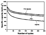
- FIG. 9 is a graph illustrating a result of battery evaluation for each binder after applying a polyacrylic acid binder, an alginate binder, and a synthetic binder to the negative electrode of the lithium ion secondary battery of FIG. 8.
- FIG. 1 is a chemical formula illustrating a synthetic binder obtained by synthesizing a first binder, a second binder, and first and second binders constituting a synthetic binder according to an embodiment of the present invention.
- a synthetic binder (PAA-Alginate) 300 is formed by chemically synthesizing a first binder 100 and a second binder 200.
- the first binder 100 for forming the synthetic binder 300 may be, for example, a material including a carboxyl group (-COOH).
- the material that can be used as the first binder 100 may include, for example, poly (acrylic acid, PAA).
- Polyacrylic acid which is the first binder 100 constituting the synthetic binder 300, provides sufficient rigidity to overcome external stress applied to the negative electrode material of the lithium ion secondary battery.
- polyacrylic acid which is the first binder 100
- PAA polyacrylic acid
- the first binder 100 has the advantage of providing strength that can overcome external stress applied to the negative electrode material of the lithium ion secondary battery
- the first binder 100 is lithium ion.
- the active material or the conductive agent may cause desorption due to volume expansion and contraction due to sedimentation problem and low binding force that are separated over time.
- the first binder 100 has an advantage of providing rigidity corresponding to external stress, sedimentation problems, desorption problems, and the like may occur.
- the second binder 200 of the synthetic binder 300 may include, for example, alginate.
- Alginate is a material extracted from seaweed, brown algae, etc. as a main material, and has a feature rich in elasticity.
- Alginate has the advantage of being able to actively cope with volume expansion and contraction caused by forming a negative electrode of a lithium ion secondary battery because of its rich elasticity, but does not have a rigidity suitable for coping with externally applied stress. Has disadvantages.
- the present invention is a polyacrylic acid (PAA) and elasticity of the first binder 100 having the advantage of providing sufficient stiffness corresponding to external stress while having the disadvantage of generating sedimentation and desorption problems
- the synthetic binder 300 is produced by chemically synthesizing alginate, an alginate, which is the second binder 200 having the disadvantage of having abundant advantages and having a disadvantage of insufficient rigidity suitable to cope with external stress.
- the synthetic binder 300 formed by synthesizing the first binder 100 and the second binder 200 has sufficient rigidity against external stress, which is an advantage of the first binder 100, and is an advantage of the second binder 200. Because it has abundant elasticity, it prevents desorption by volume expansion and contraction during charging and discharging in a lithium ion secondary battery including a silicon negative electrode, has sufficient rigidity and binding ability, and does not generate sediment over time. It has an advantage, such an advantage can greatly improve the life and characteristics of the lithium ion secondary battery.
- PAA polyacrylic acid
- alginate which is the second binder 200
- the first binder 100 polyacrylic acid (PAA) of about 5 [g] to water as a solvent Dissolve.
- PAA polyacrylic acid
- a solution provided with polyacrylic acid (PAA) and alginate is additionally added with an acid catalyst of about 0.1 [H], which serves to induce a dehydration reaction between the polyacrylic acid (PAA) and alginate in the solution.
- the ratio of the first binder 100, the second binder 200 and the reaction inducing agent may be 1: 1: 0.02.
- the solution fed with polyacrylic acid (PAA), alginate and acid catalyst is subjected to stirring for about 24 hours under reflux conditions.
- a plurality of decanes are added with ethyl acetate and diethyl ether so that trace impurities that may be generated during the synthesis of the first and second binders 100 and 200 are not included in the synthetic binder 300. Decantation is performed to remove impurities.
- the unreacted first and second binders 100 and 200 and the synthetic binder remaining after water and impurities have been removed are dried under vacuum for 24 hours to synthesize polyacrylic acid (PAA) and alginate chemically. ) Is manufactured.
- PAA polyacrylic acid
- FIG. 2 is a graph showing functional groups of the synthetic binder by FT-IR analysis of the synthetic binder shown in FIG. 1.
- PAA polyacrylic acid
- the synthetic binder 300 is about 1700 cm compared to the polyacrylic acid (PAA) included in the first binder 100 as a starting material and the alginate included in the second binder 200. It was confirmed that a specific absorption peak related to the newly introduced ester at -1 appeared.
- An absorption peak observed at about 1700 cm ⁇ 1 in the analysis graph of the synthetic binder 300 is an absorption peak not observed in the first binder 100 and the second binder 200, and the absorption peak is the synthetic binder 300.
- the carbonyl group (C O) which is a functional group produced
- generated to is shown.
- FIG. 3 is a graph illustrating 13 C-NMR (nuclear magnetic resonance) analysis of the synthetic binder shown in FIG. 1.
- FIG. 4 is a graph illustrating tensile test results of polyacrylic acid, alginate, and a synthetic binder according to an embodiment of the present invention.
- the synthetic binder 300 was analyzed to have a stiffness suitable for coping with external stress.
- FIG. 5 is a graph showing the recovery rate and the stiffness after the negative electrode mixtures including polyacrylic acid (PAA), alginate and synthetic binder are formed on the electrodes, respectively.
- PAA polyacrylic acid
- the binder containing polyacrylic acid (PAA) has a high stiffness with a relatively small depth to which the electrode is pressed, but a low recovery rate, while alginate has a relatively low stiffness and excellent recovery rate.
- Synthetic binder 300 that synthesizes polyacrylic acid (PAA) and alginate has a higher recovery rate and higher rigidity than a binder containing only polyacrylic acid (PAA) or alginate, and the recovery rate of synthetic binder 300 is polyacrylic acid (PAA). And alginate to a moderate degree, which indicates that the synthetic binder 300 has excellent elasticity compared to polyacrylic acid (PAA).
- PAA polyacrylic acid
- PAA polyacrylic acid
- an electrode is formed by using a polyacrylic acid binder on the current collector, an electrode is formed on the current collector using an alginate binder, and an electrode is formed on the current collector using a synthetic binder.
- the binding force was tested by pulling with a constant force, and the synthetic binder was found to improve the low binding force of polyacrylic acid (PAA).
- PAA polyacrylic acid
- the slurry containing polyacrylic acid may be used.
- the slurry containing polyacrylic acid may be used.
- the dispersion stability of the synthetic binder was further improved compared to polyacrylic acid.
- FIG. 8 is a cross-sectional view conceptually illustrating a lithium ion secondary battery including a negative electrode to which a negative electrode mixture including the synthetic binder shown in FIG. 1 is coated.
- the lithium ion secondary battery 500 includes a positive electrode 510, a negative electrode 520, a separator 530, and an electrolyte 540.
- the anode 510 includes an anode electrode 511 and a cathode mixture 515.
- the positive electrode mixture 515 includes a positive electrode active material including lithium oxide, a conductive agent and a binder for improving the conductivity of the positive electrode active material, and the positive electrode mixture 515 is applied or formed on the surface of the positive electrode 511.
- the negative electrode 520 includes a negative electrode 521 and a negative electrode mixture 525.
- the negative electrode 521 is spaced apart from the positive electrode 511, and the negative electrode mixture 525 improves the conductivity of the negative electrode active material and the negative electrode active material in which silicon and graphite are mixed at a ratio of 3: 7.
- the active material, the synthetic binder 300 and the conductive agent included in the negative electrode mixture 525 are prepared, for example, in a ratio of 8: 1: 1.
- the negative electrode mixture 525 is applied and formed on the surface of the negative electrode 511.
- the separator 530 has a structure having pores through which the electrolyte passes, and for example, PE (poly (ethylene)) is used.
- PE poly (ethylene)
- the electrolyte 540 includes EC: EMC at a ratio of 1: 2, and the electrolyte 540 includes 1 mol (M) of LiPF 6 and 10% of F-EC.
- PAA polyacrylic acid
- FIG. 9 is a graph illustrating a result of battery evaluation for each binder after applying a polyacrylic acid binder, an alginate binder, and a synthetic binder to the negative electrode of the lithium ion secondary battery of FIG. 8.
- the configuration of the lithium ion secondary battery is manufactured in the same form as in Figure 8, the evaluation voltage condition is 1.5 [V] to 0.01 [V], and the charge and the current density of 5 [C] Evaluation was performed by performing discharge about 300 times.
- the lithium ion secondary battery including the synthesized synthetic binder 300 was higher than the lithium ion secondary battery including the binder containing the polyacrylic acid at the first charge in terms of maintenance capacity.
- the lithium ion secondary battery including the synthetic binder 300 also includes a lithium ion secondary battery and an alginate including a binder containing polyacrylic acid in terms of holding capacity. It was higher than the lithium ion secondary battery containing the binder.
Landscapes
- Chemical & Material Sciences (AREA)
- Engineering & Computer Science (AREA)
- Chemical Kinetics & Catalysis (AREA)
- Electrochemistry (AREA)
- General Chemical & Material Sciences (AREA)
- Materials Engineering (AREA)
- Manufacturing & Machinery (AREA)
- Battery Electrode And Active Subsutance (AREA)
Abstract
본 발명은 충방전시 실리콘계 소재를 사용함에 따라 발생되는 부피 팽창 및 수축에 의한 수명 감소를 방지하기 위해 실리콘게 소재의 부피 팽창에 대응할 수 있는 풍부한 탄성, 외부 스트레스에 대응하기 위한 강성 및 결착력을 함께 갖는 리튬이온 이차전지용 바인더 및 이를 갖는 리튬이온 이차 전지를 제공하며, 리튬이온 이차전지용 바인더는 카르복실기(-COOH)를 포함하는 제1 바인더 및 알지네이트(alginate)를 포함하는 제2 바인더를 화학적으로 합성하여 강성 및 탄성을 강화시킨 합성 바인더를 포함한다.
Description
본 발명은 리튬이온 이차전지용 바인더 및 이를 갖는 리튬이온 이차 전지에 관한 것이다.
리튬이온 이차전지는 에너지를 저장하는 에너지 저장 장치의 하나이다.
리튬이온 이차전지는 니켈 카드뮴 전지 등에 비해 높은 에너지 밀도를 가지면서 비메모리(no memory effect) 특성을 갖고, 친환경적이며, 수명 주기가 길고, 높은 전압을 출력할 수 있으며, 무엇보다도 소형화가 가능하기 때문에 최근 휴대폰, 태블릿 PC 및 캠코더와 같은 소형 휴대용 전자 제품에 널리 사용되고 있다.
종래 리튬이온 이차전지는 주요 구성 요소로서 양극, 음극, 분리막 및 전해액을 포함한다.
종래 리튬이온 이차전지의 양극은 리튬산화물을 포함하며, 음극은 리튬이온을 저장할 수 있는 흑연과 같은 탄소화합물을 포함하며, 분리막은 양극과 음극이 직접 접촉되는 것을 방지하며, 전해액은 양극과 음극에서 리튬 이온이 이동할 수 있도록 하는 매개체로서 역할한다.
최근에는 리튬이온 이차전지의 음극 소재를 탄소계 소재로부터 실리콘계 소재로 변경하여 리튬이온 이차전지의 가역 용량을 증가 및 에너지 밀도를 보다 높일 수 있는 기술이 연구되고 있다.
그러나, 이와 같이 리튬이온 이차전지의 음극 소재를 탄소계 소재로부터 실리콘계 소재로 변경할 경우, 실리콘계 음극을 갖는 리튬이온 이차전지의 가역 용량 및 에너지 밀도를 증가시킬 수 있는 반면, 리튬이온 이차전지가 충방전 될 때 실리콘계 소재의 부피가 약 400% 이상 팽창에 따라 실리콘계 소재의 바인더 및 활물질이 음극으로부터 탈리되어 리튬이온 이차전지의 수명이 크게 감소되는 문제점을 갖는다.
이와 같은 리튬이온 이차전지의 음극에 실리콘계 소재를 채용함에 따라 발생되는 문제점을 해결하기 위하여 2007년 11월 20일 공개된 한국공개특허 제2007-0110569호, "바인더로서 폴리우레탄을 물리적으로 혼합한 폴리아크릴산이 포함되어 있는 전극 합제 및 이를 기반으로 하는 리튬 이차전지"에는 폴리아크릴산(PAA)에 폴리우레탄을 물리적으로 혼합한 바인더가 개시되어 있다.
리튬이온 이차전지의 실리콘계 음극의 바인더로서 폴리아크릴산(PAA)을 갖는 바인더, 실리콘계 활물질, 도전재 및 용매를 이용하여 음극 합제를 제조할 경우, 용매 내에서 실리콘계 활물질, 바인더 및 도전재를 포함하는 고형분의 침강 현상이 발생되고 침강 현상이 발생된 음극 합제를 음극에 도포할 경우 음극의 전극 밀도가 불균일해지는 문제점을 갖는다.
본 발명은 충방전시 실리콘계 소재를 사용함에 따라 발생되는 부피 팽창 및 수축에 의한 수명 감소를 방지하기 위해 실리콘게 소재의 부피 팽창에 대응할 수 있는 풍부한 탄성, 외부 스트레스에 대응하기 위한 강성 및 결착력을 함께 갖는 리튬이온 이차전지용 바인더 및 이를 갖는 리튬이온 이차 전지를 제공한다.
일실시예로서, 리튬이온 이차전지용 바인더는 카르복실기(-COOH)를 포함하는 제1 바인더 및 알지네이트(alginate)를 포함하는 제2 바인더를 화학적으로 합성하여 강성 및 탄성을 강화시킨 합성 바인더를 포함한다.
리튬이온 이차전지용 바인더의 상기 제1 바인더는 폴리아크릴산(poly(acrylic acid), PAA)을 포함한다.
리튬이온 이차전지용 바인더는의 상기 합성 바인더는 작용기로서 카보닐기(C=O)를 포함한다.
일실시예로서, 리튬이온 이차전지는 양극 전극에 양극 활물질과 도전제 및 양극 바인더를 포함하는 양극 합제가 도포된 양극, 상기 양극과 이격되며 음극 전극에 음극 활물질, 도전제 및 음극 바인더가 혼합된 음극 합제가 도포된 음극, 상기 양극 및 음극을 분리하는 분리막 및 상기 양극 및 음극 사이에서 이온 이동을 위한 전해액을 포함하며, 상기 음극 합제에 포함된 상기 음극 바인더는 카르복실기(-COOH)를 포함하는 제1 바인더 및 알지네이트(alginate)를 포함하는 제2 바인더를 화학적으로 합성하여 강성 및 탄성을 강화시킨 합성 바인더를 포함한다.
리튬이온 이차전지의 상기 제1 바인더는 폴리아크릴산(poly(acrylic acid), PAA)을 포함한다.
리튬이온 이차전지의 상기 합성 바인더는 작용기로서 카보닐기(C=O)를 포함한다.
본 발명에 따른 리튬이온 이차전지용 바인더 및 이를 갖는 리튬이온 이차 전지는 실리콘을 포함하는 음극 합제를 사용함에 따라 발생되는 충전 및 방전시 부피 팽창 및 수축에 대응하여 충분한 탄성, 강성 및 결착력을 가짐으로써 리튬이온 이차전지의 수명 감소를 방지하고, 폴리아크릴산(PAA)을 바인더로 사용할 때 발생되는 고형분의 침강 현상을 방지, 음극 합제를 전극에 균일하게 분포시켜 전극 밀도를 균일하게 형성, 우수한 결착력, 우수한 회복률, 우수한 강성을 갖도록 함으로써 리튬 이온 이차 전지의 성능을 크게 향상시킨다.
도 1은 본 발명의 일실시예에 따른 합성 바인더를 이루는 제1 바인더, 제2 바인더 및 제1 및 제2 바인더를 합성한 합성 바인더를 도시한 화학식이다.
도 2는 도 1에 도시된 합성 바인더의 FT-IR 분석에 의하여 합성 바인더의 작용기를 도시한 그래프이다.
도 3은 도 1에 도시된 합성 바인더의 13C-NMR(핵자기공명) 분석을 도시한 그래프이다.
도 4는 폴리아크릴산, 알지네이트 및 본 발명의 일실시예에 따른 합성 바인더의 인장 테스트 결과를 도시한 그래프이다.
도 5는 폴리아크릴산(PAA), 알지네이트 및 합성 바인더를 포함하는 음극 합제를 전극에 각각 형성한 후 회복률 및 강성을 도시한 그래프이다.
도 6은 폴리아크릴산(PAA), 알지네이트 및 합성 바인더의 박리 테스트를 수행한 그래프이다.
도 7은 폴리아크릴산(PAA), 알지네이트 및 합성 바인더의 침강 특성을 도시한 그래프이다.
도 8은 도 1에 도시된 합성 바인더를 포함하는 음극 합제가 도포된 음극을 포함하는 리튬 이온 이차전지를 개념적으로 도시한 단면도이다.
도 9는 도 8의 리튬이온 이차전지의 음극 전극을 폴리아크릴산 바인더, 알지네이트 바인더 및 합성 바인더를 적용한 후 바인더별로 전지평가를 수행한 결과 그래프이다.
하기의 설명에서는 본 발명의 실시 예를 이해하는데 필요한 부분만이 설명되며, 그 이외 부분의 설명은 본 발명의 요지를 흩트리지 않도록 생략될 것이라는 것을 유의하여야 한다.
이하에서 설명되는 본 명세서 및 청구범위에 사용된 용어나 단어는 통상적이거나 사전적인 의미로 한정해서 해석되어서는 아니 되며, 발명자는 그 자신의 발명을 가장 최선의 방법으로 설명하기 위해 용어의 개념으로 적절하게 정의할 수 있다는 원칙에 입각하여 본 발명의 기술적 사상에 부합하는 의미와 개념으로 해석되어야만 한다. 따라서 본 명세서에 기재된 실시예와 도면에 도시된 구성은 본 발명의 바람직한 실시예에 불과할 뿐이고, 본 발명의 기술적 사상을 모두 대변하는 것은 아니므로, 본 출원시점에 있어서 이들을 대체할 수 있는 다양한 균등물과 변형예들이 있을 수 있음을 이해하여야 한다.
도 1은 본 발명의 일실시예에 따른 합성 바인더를 이루는 제1 바인더, 제2 바인더 및 제1 및 제2 바인더를 합성한 합성 바인더를 도시한 화학식이다.
도 1을 참조하면, 합성 바인더(PAA-Alginate, 300)는 제1 바인더(100) 및 제2 바인더(200)를 화학적으로 합성하여 형성된다.
합성 바인더(300)를 형성하기 위한 제1 바인더(100)는, 예를 들어, 카르복실기(-COOH)를 포함하는 물질일 수 있다.
본 발명의 일실시예에서, 제1 바인더(100)로서 사용될 수 있는 물질은, 예를 들어, 폴리아크릴산(poly(acrylic acid), PAA)을 포함할 수 있다.
합성 바인더(300)를 이루는 제1 바인더(100)인 폴리아크릴산(PAA)은 리튬이온 이차전지의 음극 소재에 인가되는 외부 스트레스를 극복할 수 있는 충분한 강성을 제공한다.
그러나, 제1 바인더(100)인 폴리아크릴산(PAA)은 리튬이온 이차전지의 음극 소재에 인가되는 외부 스트레스를 극복할 수 있는 강도를 제공하는 장점을 갖는 반면, 제1 바인더(100)를 리튬이온 이차전지의 음극 소재에 적용되는 단독 바인더로 사용할 경우, 활물질 또는 도전제가 시간의 경과에 따라 분리되는 침강 문제 및 낮은 결착력에 의하여 부피 팽창 및 수축에 따른 탈리를 발생 시킬 수 있다.
즉, 제1 바인더(100)는 외부 스트레스에 대응하는 강성을 제공할 수 있는 장점을 갖는 반면 침강 문제, 탈리 문제 등이 발생될 수 있다.
합성 바인더(300)의 제2 바인더(200)는, 예를 들어, 알지네이트(alginate)를 포함할 수 있다.
알지네이트는 해조류, 갈조류 등에서 추출한 물질을 주재료로 하며, 탄성이 풍부한 특징을 갖는다.
알지네이트는 탄성이 풍부하기 때문에 리튬이온 이차전지의 음극을 실리콘 소재로 형성함으로써 발생되는 부피 팽창 및 수축에 능동적으로 대응할 수 있는 장점을 갖는 반면, 외부에서 인가되는 스트레스에 대응하기에 적합한 강성을 갖지 못하는 단점을 갖는다.
본 발명의 일실시예에서는 외부 스트레스에 대응하는 충분한 강성을 제공할 수 있는 장점을 갖는 반면 침강 문제 및 탈리 문제를 발생시킬 수 있는 단점을 갖는 제1 바인더(100)인 폴리아크릴산(PAA) 및 탄성이 풍부한 장점을 갖는 반면 외부 스트레스에 대응하기에 적합한 강성이 부족한 단점을 갖는 제2 바인더(200)인 알지네이트(alginate)를 화학적으로 합성하여 합성 바인더(300)를 생성한다.
제1 바인더(100) 및 제2 바인더(200)를 합성하여 형성된 합성 바인더(300)는 제1 바인더(100)의 장점인 외부 스트레스에 대한 충분한 강성을 갖고, 제2 바인더(200)의 장점인 풍부한 탄성을 모두 갖기 때문에 실리콘 소재의 음극을 포함하는 리튬이온 이차전지에서 충전 및 방전 시 부피 팽창 및 수축에 의한 탈리를 방지, 충분한 강성 및 결착력을 가지며, 시간의 경과에 따른 침강이 발생되지 않는 다양한 장점을 가지며, 이와 같은 장점은 리튬이온 이차전지의 수명 및 특성을 크게 향상시킬 수 있다.
본 발명의 일실시예에서 제1 바인더(100)인 폴리아크릴산(PAA) 및 제2 바인더(200)인 알지네이트를 합성하여 형성된 합성 바인더(300)는 작용기로서 카보닐기(C=O)를 포함한다.
본 발명의 일실시예에서, 도 1에 도시된 합성 바인더(300)를 합성하기 위해서는, 예를 들어, 제1 바인더(100)인 약 5[g]의 폴리아크릴산(PAA)를 용매인 물에 용해시킨다.
이어서, 폴리아크릴산(PAA)이 용해된 용액 내에 약 5[g]의 알지네이트(alginate)를 제공한다.
폴리아크릴산(PAA) 및 알지네이트가 제공된 용액에는 추가적으로 약 0.1[ㅎ]의 산 촉매가 추가적으로 투입되는데, 산 촉매는 용액 내의 폴리아크릴산(PAA) 및 알지네이트간 탈수 반응을 유도하는 역할을 한다.
본 발명의 일실시예에서, 제1 바인더(100), 제2 바인더(200) 및 반응 유도제의 비율은 1:1:0.02일 수 있다.
폴리아크릴산(PAA), 알지네이트 및 산 촉매가 투입된 용액은 환류(reflux) 조건하에서 약 24시간 동안 교반이 실시된다.
약 24시간 교반이 실시된 후 남은 여액은 감안 증류장치를 통해 제거한다.
이어서, 제1 및 제2 바인더(100,200)를 합성하는 도중 생성될 수 있는 미량의 불순물이 합성 바인더(300)에 포함되지 않도록 에틸 아세테이트(ethyl acetate) 및 디에틸 에테르(diethyl ether)로 복수번 디캔테이션(decantation)을 수행하여 불순물을 제거한다.
이후, 미반응 제1 및 제2 바인더(100,200), 물 및 불순물이 제거된 후 남은 합성 바인더를 진공하에서 24시간 건조시켜 폴리아크릴산(PAA) 및 알지네이트(alginate)를 화학적으로 합성한 합성 바인더(300)가 제조된다.
이하, 폴리아크릴산(PAA) 및 알지네이트를 합성한 합성 바인더(300)의 작용 및 특성을 설명하기로 한다.
도 2는 도 1에 도시된 합성 바인더의 FT-IR 분석에 의하여 합성 바인더의 작용기를 도시한 그래프이다.
도 1 및 도 2를 참조하면, 제1 바인더(100)인 폴리아크릴산(PAA) 및 제2 바인더(200)인 알지네이트(alginate)를 합성한 합성 바인더(300)의 FT-IR 분석에 의하여 합성 바인더(300)의 화학적 구조분석을 수행한 결과, 합성 바인더(300)는 출발 물질인 제1 바인더(100)에 포함된 폴리아크릴산(PAA) 및 제2 바인더(200)에 포함된 알지네이트 대비 약 1700 cm-1에서 새롭게 도입된 에스터(ester)에 관계되는 특이한 흡광 피크(absorbance peak)가 나타나는 것이 확인되었다.
합성 바인더(300)의 분석 그래프 중 약 1700 cm-1에서 관찰되는 흡광 피크는 제1 바인더(100) 및 제2 바인더(200)에서 관찰되지 않는 흡광 피크로서, 이 흡광 피크는 합성 바인더(300)에 생성된 작용기인 카보닐기(C=O)를 나타낸다.
도 3은 도 1에 도시된 합성 바인더의 13C-NMR(핵자기공명) 분석을 도시한 그래프이다.
도 1 및 도 3을 참조하면, 합성 바인더(300)를 13C-NMR(핵자기공명) 분석을 수행한 바, 기존 폴리아크릴산(PAA) 및 알지네이트에 각각 포함된 카르복실기(-COOH)가 쉬프트되고 이로 인해 제1 바인더(100) 및 제2 바인더(200)를 중합하여 합성된 합성 바인더(300)에 카보닐기(C=O)가 성공적으로 형성된 것을 확인할 수 있다.
도 4는 폴리아크릴산, 알지네이트 및 본 발명의 일실시예에 따른 합성 바인더의 인장 테스트 결과를 도시한 그래프이다.
도 1 및 도 4를 참조하면, 폴리아크릴산(PAA), 알지네이트(alginate) 및 합성 바인더(PAA-Alginate,300)를 각각 동일한 조건에서 인장 테스트를 수행한 결과, 알지네이트는 가장 낮은 인장 강도를 갖고 폴리아크릴산(PAA)은 가장 높은 인장 강도를 갖는다. 반면, 합성 바인더(300)는 도 4에 도시된 바와 같이 폴리아크릴산(PAA)보다는 낮지만 알지네이트 보다는 높은 인장 강도를 갖고 있는다.
도 4에 의하면, 합성 바인더(300)의 경우 외부 스트레스에 대응하기에 적합한 강성을 갖는 것으로 분석되었다.
도 5는 폴리아크릴산(PAA), 알지네이트 및 합성 바인더를 포함하는 음극 합제를 전극에 각각 형성한 후 회복률 및 강성을 도시한 그래프이다.
도 5를 참조하면, 폴리아크릴산(PAA), 알지네이트 및 합성 바인더를 포함하는 음극 합제를 전극에 각각 제조한 후 microindentor를 이용한 회복률 및 강성 평가를 진행한 결과, 각 전극들에 약 10mN의 힘을 인가하여 전극들이 눌려 들어가는 깊이인 강성을 측정한다.
이후, 약 10mN의 힘을 제거 한 다음 회복되는 정도인 회복률을 측정하여 바인더에 따른 전극의 회복률 및 강성을 분석하였다.
폴리아크릴산(PAA)을 포함하는 바인더는 전극이 눌려들어가는 깊이가 상대적으로 적은 높은 강성을 갖지만 회복률이 낮은 반면, 알지네이트는 상대적으로 강성이 낮고 회복률이 우수한 특성을 갖는다.
폴리아크릴산(PAA) 및 알지네이트를 합성한 합성 바인더(300)는 폴리아크릴산(PAA) 또는 알지네이트만을 포함하는 바인더 대비 높은 회복률 및 높은 강성을 가지고 있으며, 합성 바인더(300)의 회복률은 폴리아크릴산(PAA) 및 알지네이트의 중간 정도였으며, 이는 합성 바인더(300)의 경우 폴리아크릴산(PAA) 대비 탄성이 우수한 것을 나타낸다.
도 6은 폴리아크릴산(PAA), 알지네이트 및 합성 바인더의 박리 테스트를 수행한 그래프이다.
도 6의 그래프에 의하면, 집전체에 폴리아크릴산 바인더를 이용하여 전극을 형성, 집전체에 알지네이트 바인더를 이용하여 전극을 형성 및 집전체에 합성 바인더를 이용하여 전극을 형성한 후 각 전극에 접착 테이프를 붙인 후 일정 힘으로 당켜 결착력을 테스트한 결과 합성 바인더의 경우 폴리아크릴산(PAA)의 낮은 결착력을 개선하는 것으로 나타났다.
도 7은 폴리아크릴산(PAA), 알지네이트 및 합성 바인더의 침강 특성을 도시한 그래프이다.
도 7을 참조하면, 폴리아크릴산, 알지네이트 및 합성 바인더에 활물질 및 도전제를 혼합하여 슬러리를 형성한 후 1 주(week)가 경과된 후 슬러리의 침강 여부를 확인하면, 폴리아크릴산을 포함하는 슬러리의 경우 약 20%의 침강 현상이 발생되었지만, 합성 바인더의 경우 약 2%의 침강 현상이 발생되었으며, 이로 인해 합성 바인더의 경우 분산 안정성이 폴리아크릴산 대비 한층 개선되는 것으로 나타났다.
도 8은 도 1에 도시된 합성 바인더를 포함하는 음극 합제가 도포된 음극을 포함하는 리튬 이온 이차전지를 개념적으로 도시한 단면도이다.
도 1 및 도 8을 참조하면, 리튬 이온 이차전지(500)는 양극(510), 음극(520), 분리막(530) 및 전해액(540)을 포함한다.
양극(510)은 양극 전극(511) 및 양극 합제(515)를 포함한다.
양극 합제(515)는 리튬 산화물을 포함하는 양극 활물질, 양극 활물질의 도전성을 향상시키는 도전제 및 바인더를 포함하며, 양극 합제(515)는 양극 전극(511)의 표면에 도포 또는 형성된다.
음극(520)은 음극 전극(521) 및 음극 합제(525)를 포함한다.
음극 전극(521)은 양극 전극(511)과 이격되어 배치되며, 음극 합제(525)는 실리콘(silicon) 및 흑연(graphite)이 3:7의 비율로 혼합된 음극 활물질, 음극 활물질의 도전성을 향상시키는 도전제 및 도 1에 도시된 합성 바인더(300)를 포함한다.
본 발명의 일실시예에서, 음극 합제(525)에 포함되는 활물질, 합성 바인더(300) 및 도전제는, 예를 들어, 8:1:1의 비율로 제조된다. 음극 합제(525)는 음극 전극(511)의 표면에 도포 및 형성된다.
분리막(530)은 전해액이 통과하는 다공을 갖는 구조를 가지며, 분리막은, 예를 들어, PE(poly(ethylene)가 사용된다.
전해액(540)은 EC:EMC가 1:2의 비율로 포함되며, 전해액(540)은 1몰(M)의 LiPF6 및 10%의 F-EC를 포함한다.
본 발명의 일실시예에서, 음극 합제(525)에 포함된 합성 바인더는 도 1에 도시된 바와 같이 카르복실산을 포함하는 폴리아크릴산(PAA)을 포함하는 제1 바인더(100) 및 알지네이트(alginate)를 포함하는 제2 바인더를 화학적으로 합성하여 형성되며, 합성 바인더(300)는 작용기로서 카보닐기(C=O)를 포함한다.
도 9는 도 8의 리튬이온 이차전지의 음극 전극을 폴리아크릴산 바인더, 알지네이트 바인더 및 합성 바인더를 적용한 후 바인더별로 전지평가를 수행한 결과 그래프이다.
도 1 및 도 9를 참조하면, 리튬 이온 이차 전지의 구성은 도 8과 동일한 형태로 제조되며, 평가 전압 조건은 1.5[V] 내지 0.01[V]이며, 5 [C]의 전류밀도로 충전 및 방전을 약 300회 수행하여 평가를 하였다.
평가 결과 합성된 합성 바인더(300)를 포함하는 리튬이온 이차전지의 경우 유지 용량 측면에서 첫 번째 충전시 폴리아크릴산을 포함하는 바인더를 포함하는 리튬이온 이차전지 보다 높았다.
한편, 300번 충전 및 방전을 반복하여 수행한 후, 합성 바인더(300)를 포함하는 리튬이온 이차전지의 경우에도 유지 용량 측면에서 폴리아크릴산을 포함하는 바인더를 포함하는 리튬이온 이차전지 및 알지네이트를 포함하는 바인더를 포함하는 리튬이온 이차전지보다 높았다.
이상에서 상세하게 설명한 바에 의하면, 실리콘을 포함하는 음극 합제를 사용함에 따라 발생되는 충전 및 방전시 부피 팽창 및 수축에 대응하여 충분한 탄성, 강성 및 결착력을 가짐으로써 리튬이온 이차전지의 수명 감소를 방지하고, 폴리아크릴산(PAA)을 바인더로 사용할 때 발생되는 고형분의 침강 현상을 방지, 음극 합제를 전극에 균일하게 분포시켜 전극 밀도를 균일하게 형성, 우수한 결착력, 우수한 회복률, 우수한 강성을 갖도록 함으로써 리튬 이온 이차 전지의 성능을 크게 향상시킨다.
한편, 본 도면에 개시된 실시예는 이해를 돕기 위해 특정 예를 제시한 것에 지나지 않으며, 본 발명의 범위를 한정하고자 하는 것은 아니다. 여기에 개시된 실시예 이외에도 본 발명의 기술적 사상에 바탕을 둔 다른 변형예들이 실시 가능하다는 것은, 본 발명이 속하는 기술분야에서 통상의 지식을 가진 자에게는 자명한 것이다.
Claims (6)
- 카르복실기(-COOH)를 포함하는 제1 바인더 및 알지네이트(alginate)를 포함하는 제2 바인더를 화학적으로 합성하여 강성 및 탄성을 강화시킨 합성 바인더를 포함하는 리튬이온 이차전지용 바인더.
- 제1항에 있어서,상기 제1 바인더는 폴리아크릴산(poly(acrylic acid), PAA)을 포함하는 리튬이온 이차전지용 바인더.
- 제1항에 있어서,상기 합성 바인더는 작용기로서 카보닐기(C=O)를 포함하는 리튬이온 이차 전지용 바인더.
- 양극 전극에 양극 활물질과 도전제 및 양극 바인더를 포함하는 양극 합제가 도포된 양극;상기 양극과 이격되며 음극 전극에 음극 활물질, 도전제 및 음극 바인더가 혼합된 음극 합제가 도포된 음극;상기 양극 및 음극을 분리하는 분리막; 및상기 양극 및 음극 사이에서 이온 이동을 위한 전해액을 포함하며,상기 음극 합제에 포함된 상기 음극 바인더는 카르복실기(-COOH)를 포함하는 제1 바인더 및 알지네이트(alginate)를 포함하는 제2 바인더를 화학적으로 합성하여 강성 및 탄성을 강화시킨 합성 바인더를 포함하는 리튬이온 이차전지.
- 제4항에 있어서,상기 제1 바인더는 폴리아크릴산(poly(acrylic acid), PAA)을 포함하는 리튬이온 이차전지.
- 제4항에 있어서,상기 합성 바인더는 작용기로서 카보닐기(C=O)를 포함하는 리튬이온 이차 전지.
Applications Claiming Priority (2)
| Application Number | Priority Date | Filing Date | Title |
|---|---|---|---|
| KR10-2015-0032190 | 2015-03-09 | ||
| KR1020150032190A KR101647405B1 (ko) | 2015-03-09 | 2015-03-09 | 리튬이온 이차전지용 바인더 및 이를 갖는 리튬이온 이차 전지 |
Publications (1)
| Publication Number | Publication Date |
|---|---|
| WO2016143977A1 true WO2016143977A1 (ko) | 2016-09-15 |
Family
ID=56714286
Family Applications (1)
| Application Number | Title | Priority Date | Filing Date |
|---|---|---|---|
| PCT/KR2015/012128 Ceased WO2016143977A1 (ko) | 2015-03-09 | 2015-11-11 | 리튬이온 이차전지용 바인더 및 이를 갖는 리튬이온 이차 전지 |
Country Status (2)
| Country | Link |
|---|---|
| KR (1) | KR101647405B1 (ko) |
| WO (1) | WO2016143977A1 (ko) |
Families Citing this family (2)
| Publication number | Priority date | Publication date | Assignee | Title |
|---|---|---|---|---|
| KR20240129526A (ko) | 2023-02-20 | 2024-08-27 | 주식회사 엘지에너지솔루션 | 리튬 이차전지 및 이의 제조 방법 |
| KR20250161847A (ko) * | 2024-05-09 | 2025-11-18 | 주식회사 에이엔폴리 | 리튬 이온 전지용 바인더 조성물, 이의 제조 방법, 이를 포함하는 슬러리 조성물, 양극 및 리튬 이온 전지 |
Citations (4)
| Publication number | Priority date | Publication date | Assignee | Title |
|---|---|---|---|---|
| US20120088155A1 (en) * | 2010-05-03 | 2012-04-12 | Gleb Yushin | Alginate-containing compositions for use in battery applications |
| KR20130123831A (ko) * | 2012-05-04 | 2013-11-13 | 한국과학기술원 | 리튬 이온전지 전극 바인더 및 그 제조방법, 및 이를 이용한 리튬이차전지 전극 |
| KR20140039244A (ko) * | 2011-06-29 | 2014-04-01 | 닛토덴코 가부시키가이샤 | 비수전해액 이차 전지와 그것을 위한 정극 시트 |
| KR20140072583A (ko) * | 2012-12-05 | 2014-06-13 | 한국과학기술원 | 금속이온 이동 억제용 리튬이차전지 전극 바인더 물질 및 이를 포함하는 리튬이차전지 |
Family Cites Families (1)
| Publication number | Priority date | Publication date | Assignee | Title |
|---|---|---|---|---|
| KR100863733B1 (ko) | 2006-05-15 | 2008-10-16 | 주식회사 엘지화학 | 바인더로서 폴리우레탄을 물리적으로 혼합한폴리아크릴산이 포함되어 있는 전극 합제 및 이를 기반으로하는 리튬 이차전지 |
-
2015
- 2015-03-09 KR KR1020150032190A patent/KR101647405B1/ko not_active Expired - Fee Related
- 2015-11-11 WO PCT/KR2015/012128 patent/WO2016143977A1/ko not_active Ceased
Patent Citations (4)
| Publication number | Priority date | Publication date | Assignee | Title |
|---|---|---|---|---|
| US20120088155A1 (en) * | 2010-05-03 | 2012-04-12 | Gleb Yushin | Alginate-containing compositions for use in battery applications |
| KR20140039244A (ko) * | 2011-06-29 | 2014-04-01 | 닛토덴코 가부시키가이샤 | 비수전해액 이차 전지와 그것을 위한 정극 시트 |
| KR20130123831A (ko) * | 2012-05-04 | 2013-11-13 | 한국과학기술원 | 리튬 이온전지 전극 바인더 및 그 제조방법, 및 이를 이용한 리튬이차전지 전극 |
| KR20140072583A (ko) * | 2012-12-05 | 2014-06-13 | 한국과학기술원 | 금속이온 이동 억제용 리튬이차전지 전극 바인더 물질 및 이를 포함하는 리튬이차전지 |
Non-Patent Citations (2)
| Title |
|---|
| KOO, BON JAE ET AL.: "A highly Cross-linked Polymeric Binder for High-performance Silicon Negative Electrodes in Lithium Ion Batteries", ANGEWANDTE CHEMIE, vol. 51, no. 35, 2012, pages 8762 - 8767, XP055309328 * |
| KOVALENKO, IGOR ET AL.: "A Major Constituent of Brown Algae for Use in High-capacity Li-ion Batteries", SCIENCE, vol. 334, no. 75, 2011, pages 75 - 79, XP055067920 * |
Also Published As
| Publication number | Publication date |
|---|---|
| KR101647405B1 (ko) | 2016-08-11 |
Similar Documents
| Publication | Publication Date | Title |
|---|---|---|
| WO2010080009A2 (ko) | 공융혼합물과 니트릴 화합물을 포함하는 전해질 및 이를 구비한 전기화학소자 | |
| CN107331892B (zh) | 一种电解液、正极及其制备方法和一种锂离子电池 | |
| WO2017030309A1 (ko) | 전지 충전 한계 예측 방법과 이를 이용한 전지 급속 충전 방법 및 장치 | |
| KR20160052323A (ko) | 리튬 전극 및 이를 포함하는 리튬 전지 | |
| WO2011159051A2 (ko) | 전기화학소자용 전해질, 그 제조방법 및 이를 구비한 전기화학소자 | |
| WO2018056782A1 (ko) | 리튬-황 이차전지 양극용 아크릴 바인더 및 이의 용도 | |
| WO2015065090A1 (ko) | 전극-분리막 복합체의 제조방법, 그 제조방법에 의해 제조된 전극-분리막 복합체 및 그를 포함하는 리튬 이차전지 | |
| CN113851656A (zh) | 一种负极极片及包括该负极极片的锂离子电池 | |
| US12347862B2 (en) | Anode slurry composition | |
| WO2017061807A1 (ko) | 전극조립체를 구성하는 분리막의 기공 내에 겔화 전해액 성분을 포함하고 있는 전지셀 | |
| CN113871699A (zh) | 一种固态电解质及包括该固态电解质的锂离子电池 | |
| US20160020449A1 (en) | Electrically-polymerized surface layer for artificial solid-electrolyte-interphase (sei) layers on silicon and carbon based electrodes | |
| WO2015147419A1 (ko) | 리튬이온 이차전지용 음극 합제, 이의 제조 방법 및 이를 갖는 리튬이온 이차 전지 | |
| WO2016143977A1 (ko) | 리튬이온 이차전지용 바인더 및 이를 갖는 리튬이온 이차 전지 | |
| WO2015190832A1 (ko) | 실리콘-탄소 복합체, 이를 포함하는 음극, 상기 실리콘-탄소 복합체를 이용하는 이차 전지 및 상기 실리콘-탄소 복합체의 제조방법 | |
| JP2008226606A (ja) | リチウム二次電池の製造方法 | |
| WO2016082657A1 (zh) | 锂金属电极及其制备方法以及锂二次电池 | |
| WO2015080357A1 (ko) | 리튬 설퍼 전지 전극 보호막을 포함하는 리튬 설퍼 전지 및 이의 제조 방법 | |
| CN113851655A (zh) | 一种负极极片及包括该负极极片的锂离子电池 | |
| WO2015147418A1 (ko) | 리튬이온 이차전지용 바인더, 이의 제조 방법 및 이를 갖는 리튬이온 이차 전지 | |
| KR20170103053A (ko) | 리튬이온 이차전지의 실리콘계 음극 소재용 바인더 및 이의 제조 방법 | |
| KR102136550B1 (ko) | 바인더 | |
| WO2014142523A1 (ko) | 리튬의 프리도핑 방법, 상기 방법을 포함하는 리튬 이차전지의 제조방법, 및 상기 제조방법으로부터 제조된 리튬 이차전지 | |
| WO2013065918A1 (ko) | 리튬 이차전지용 양극 활물질의 제조 방법 | |
| KR20170099005A (ko) | 리튬이온 이차전지의 실리콘계 음극 소재용 바인더 및 이의 제조 방법 |
Legal Events
| Date | Code | Title | Description |
|---|---|---|---|
| 121 | Ep: the epo has been informed by wipo that ep was designated in this application |
Ref document number: 15884776 Country of ref document: EP Kind code of ref document: A1 |
|
| NENP | Non-entry into the national phase |
Ref country code: DE |
|
| 122 | Ep: pct application non-entry in european phase |
Ref document number: 15884776 Country of ref document: EP Kind code of ref document: A1 |