WO2016143429A1 - 石炭改質プラント及び改質石炭の製造方法 - Google Patents
石炭改質プラント及び改質石炭の製造方法 Download PDFInfo
- Publication number
- WO2016143429A1 WO2016143429A1 PCT/JP2016/053482 JP2016053482W WO2016143429A1 WO 2016143429 A1 WO2016143429 A1 WO 2016143429A1 JP 2016053482 W JP2016053482 W JP 2016053482W WO 2016143429 A1 WO2016143429 A1 WO 2016143429A1
- Authority
- WO
- WIPO (PCT)
- Prior art keywords
- coal
- carrier gas
- scrubber
- mercury
- gas
- Prior art date
- Legal status (The legal status is an assumption and is not a legal conclusion. Google has not performed a legal analysis and makes no representation as to the accuracy of the status listed.)
- Ceased
Links
Images

Classifications
-
- C—CHEMISTRY; METALLURGY
- C10—PETROLEUM, GAS OR COKE INDUSTRIES; TECHNICAL GASES CONTAINING CARBON MONOXIDE; FUELS; LUBRICANTS; PEAT
- C10B—DESTRUCTIVE DISTILLATION OF CARBONACEOUS MATERIALS FOR PRODUCTION OF GAS, COKE, TAR, OR SIMILAR MATERIALS
- C10B53/00—Destructive distillation, specially adapted for particular solid raw materials or solid raw materials in special form
- C10B53/04—Destructive distillation, specially adapted for particular solid raw materials or solid raw materials in special form of powdered coal
-
- F—MECHANICAL ENGINEERING; LIGHTING; HEATING; WEAPONS; BLASTING
- F26—DRYING
- F26B—DRYING SOLID MATERIALS OR OBJECTS BY REMOVING LIQUID THEREFROM
- F26B5/00—Drying solid materials or objects by processes not involving the application of heat
- F26B5/16—Drying solid materials or objects by processes not involving the application of heat by contact with sorbent bodies, e.g. absorbent mould; by admixture with sorbent materials
-
- B—PERFORMING OPERATIONS; TRANSPORTING
- B01—PHYSICAL OR CHEMICAL PROCESSES OR APPARATUS IN GENERAL
- B01D—SEPARATION
- B01D53/00—Separation of gases or vapours; Recovering vapours of volatile solvents from gases; Chemical or biological purification of waste gases, e.g. engine exhaust gases, smoke, fumes, flue gases, aerosols
-
- B—PERFORMING OPERATIONS; TRANSPORTING
- B01—PHYSICAL OR CHEMICAL PROCESSES OR APPARATUS IN GENERAL
- B01D—SEPARATION
- B01D53/00—Separation of gases or vapours; Recovering vapours of volatile solvents from gases; Chemical or biological purification of waste gases, e.g. engine exhaust gases, smoke, fumes, flue gases, aerosols
- B01D53/14—Separation of gases or vapours; Recovering vapours of volatile solvents from gases; Chemical or biological purification of waste gases, e.g. engine exhaust gases, smoke, fumes, flue gases, aerosols by absorption
-
- B—PERFORMING OPERATIONS; TRANSPORTING
- B01—PHYSICAL OR CHEMICAL PROCESSES OR APPARATUS IN GENERAL
- B01D—SEPARATION
- B01D53/00—Separation of gases or vapours; Recovering vapours of volatile solvents from gases; Chemical or biological purification of waste gases, e.g. engine exhaust gases, smoke, fumes, flue gases, aerosols
- B01D53/34—Chemical or biological purification of waste gases
- B01D53/74—General processes for purification of waste gases; Apparatus or devices specially adapted therefor
- B01D53/77—Liquid phase processes
- B01D53/78—Liquid phase processes with gas-liquid contact
-
- C—CHEMISTRY; METALLURGY
- C10—PETROLEUM, GAS OR COKE INDUSTRIES; TECHNICAL GASES CONTAINING CARBON MONOXIDE; FUELS; LUBRICANTS; PEAT
- C10B—DESTRUCTIVE DISTILLATION OF CARBONACEOUS MATERIALS FOR PRODUCTION OF GAS, COKE, TAR, OR SIMILAR MATERIALS
- C10B57/00—Other carbonising or coking processes; Features of destructive distillation processes in general
- C10B57/08—Non-mechanical pretreatment of the charge, e.g. desulfurization
- C10B57/10—Drying
-
- C—CHEMISTRY; METALLURGY
- C10—PETROLEUM, GAS OR COKE INDUSTRIES; TECHNICAL GASES CONTAINING CARBON MONOXIDE; FUELS; LUBRICANTS; PEAT
- C10L—FUELS NOT OTHERWISE PROVIDED FOR; NATURAL GAS; SYNTHETIC NATURAL GAS OBTAINED BY PROCESSES NOT COVERED BY SUBCLASSES C10G OR C10K; LIQUIFIED PETROLEUM GAS; USE OF ADDITIVES TO FUELS OR FIRES; FIRE-LIGHTERS
- C10L5/00—Solid fuels
- C10L5/02—Solid fuels such as briquettes consisting mainly of carbonaceous materials of mineral or non-mineral origin
- C10L5/34—Other details of the shaped fuels, e.g. briquettes
- C10L5/36—Shape
- C10L5/38—Briquettes consisting of different layers
-
- C—CHEMISTRY; METALLURGY
- C10—PETROLEUM, GAS OR COKE INDUSTRIES; TECHNICAL GASES CONTAINING CARBON MONOXIDE; FUELS; LUBRICANTS; PEAT
- C10L—FUELS NOT OTHERWISE PROVIDED FOR; NATURAL GAS; SYNTHETIC NATURAL GAS OBTAINED BY PROCESSES NOT COVERED BY SUBCLASSES C10G OR C10K; LIQUIFIED PETROLEUM GAS; USE OF ADDITIVES TO FUELS OR FIRES; FIRE-LIGHTERS
- C10L9/00—Treating solid fuels to improve their combustion
- C10L9/08—Treating solid fuels to improve their combustion by heat treatments, e.g. calcining
- C10L9/083—Torrefaction
-
- F—MECHANICAL ENGINEERING; LIGHTING; HEATING; WEAPONS; BLASTING
- F26—DRYING
- F26B—DRYING SOLID MATERIALS OR OBJECTS BY REMOVING LIQUID THEREFROM
- F26B11/00—Machines or apparatus for drying solid materials or objects with movement which is non-progressive
- F26B11/02—Machines or apparatus for drying solid materials or objects with movement which is non-progressive in moving drums or other mainly-closed receptacles
- F26B11/04—Machines or apparatus for drying solid materials or objects with movement which is non-progressive in moving drums or other mainly-closed receptacles rotating about a horizontal or slightly-inclined axis
- F26B11/0445—Machines or apparatus for drying solid materials or objects with movement which is non-progressive in moving drums or other mainly-closed receptacles rotating about a horizontal or slightly-inclined axis having conductive heating arrangements, e.g. heated drum wall
-
- F—MECHANICAL ENGINEERING; LIGHTING; HEATING; WEAPONS; BLASTING
- F26—DRYING
- F26B—DRYING SOLID MATERIALS OR OBJECTS BY REMOVING LIQUID THEREFROM
- F26B21/00—Arrangements for supplying or controlling air or other gases for drying solid materials or objects
- F26B21/40—Arrangements for supplying or controlling air or other gases for drying solid materials or objects using gases other than air
-
- F—MECHANICAL ENGINEERING; LIGHTING; HEATING; WEAPONS; BLASTING
- F26—DRYING
- F26B—DRYING SOLID MATERIALS OR OBJECTS BY REMOVING LIQUID THEREFROM
- F26B23/00—Heating arrangements
- F26B23/10—Heating arrangements using tubes or passages containing heated fluids, e.g. acting as radiative elements; Closed-loop systems
-
- B—PERFORMING OPERATIONS; TRANSPORTING
- B01—PHYSICAL OR CHEMICAL PROCESSES OR APPARATUS IN GENERAL
- B01D—SEPARATION
- B01D2252/00—Absorbents, i.e. solvents and liquid materials for gas absorption
- B01D2252/10—Inorganic absorbents
- B01D2252/103—Water
-
- B—PERFORMING OPERATIONS; TRANSPORTING
- B01—PHYSICAL OR CHEMICAL PROCESSES OR APPARATUS IN GENERAL
- B01D—SEPARATION
- B01D2257/00—Components to be removed
- B01D2257/60—Heavy metals or heavy metal compounds
- B01D2257/602—Mercury or mercury compounds
-
- Y—GENERAL TAGGING OF NEW TECHNOLOGICAL DEVELOPMENTS; GENERAL TAGGING OF CROSS-SECTIONAL TECHNOLOGIES SPANNING OVER SEVERAL SECTIONS OF THE IPC; TECHNICAL SUBJECTS COVERED BY FORMER USPC CROSS-REFERENCE ART COLLECTIONS [XRACs] AND DIGESTS
- Y02—TECHNOLOGIES OR APPLICATIONS FOR MITIGATION OR ADAPTATION AGAINST CLIMATE CHANGE
- Y02E—REDUCTION OF GREENHOUSE GAS [GHG] EMISSIONS, RELATED TO ENERGY GENERATION, TRANSMISSION OR DISTRIBUTION
- Y02E50/00—Technologies for the production of fuel of non-fossil origin
- Y02E50/10—Biofuels, e.g. bio-diesel
Definitions
- the present invention relates to a coal reforming plant for carbonizing after drying coal and a method for producing the reformed coal.
- Low-grade coals such as sub-bituminous coal and lignite have low calorific value per unit weight because they are not carbonized and have a high moisture content compared to high-grade coal.
- low grade coal is abundant in reserves, so its effective use is desired.
- various coal reforming technologies have been studied that increase the calorific value by dry distillation after drying low-grade coal and inactivate the reformed coal to prevent spontaneous ignition during transportation and storage. (For example, JP-A-2014-31462).
- mercury in dry distillation coal is obtained by re-adsorbing mercury-based substances (HgS, HgCl 2, etc.) contained in the dry distillation gas generated when dry distillation of coal to the dry distillation coal.
- mercury-based substances HgS, HgCl 2, etc.
- pulverized coal is supplied into a dry distillation furnace, a mercury-based substance is adsorbed on the pulverized coal and discharged out of the system.
- the temperature at which the coal is carbonized is 300 ° C. or more and 500 ° C. or less, and the evaporation temperature of mercury is about 400 ° C.
- the mercury-based material in the carbonization device is Considering the occurrence is technically reasonable. Under such an understanding, since the drying apparatus before the carbonization is heated to 150 ° C. or more and 200 ° C. or less to remove moisture in the coal, generation of mercury and / or mercury-based substances is negligible. It was thought to be small.
- the present invention has been made in view of such circumstances, and provides a coal reforming plant and a method for producing reformed coal capable of removing mercury and / or mercury-based substances generated in a drying apparatus.
- the purpose is to do.
- the coal reforming plant and the method for producing reformed coal of the present invention employ the following means. That is, in the coal reforming plant according to one aspect of the present invention, a drying apparatus that heats and drys coal before carbonization, and the coal is desorbed from the coal when dried by the drying apparatus. And a scrubber for treating the carrier gas discharged from the drying device with the desorbed component.
- the coal is heated and dried by a drying device before the coal is distilled to reduce the moisture content of the coal.
- a carrier gas is passed through the drying device in order to discharge the desorbed components desorbed from the coal when the coal is dried.
- the desorption component discharged with the carrier gas is water vapor or pulverized coal, but as a result of intensive studies by the present inventors, it contains a non-negligible amount of mercury and / or mercury-based substances. There was found. Mercury and / or mercury-based substances generated in the drying apparatus are removed by the scrubber.
- the coal reforming plant according to an aspect of the present invention includes a carrier gas circulation path that guides the carrier gas after being processed by the scrubber to the drying device.
- the carrier gas By introducing the carrier gas after being processed by the scrubber to the drying device through the carrier gas circulation path, the carrier gas was circulated and reused. Thereby, the consumption of carrier gas can be reduced. If the carrier gas is circulated without removing mercury and / or mercury-based material, the mercury and / or mercury-based material will be concentrated in the drying device, so the mercury and / or mercury-based material is removed by the scrubber. This is particularly effective.
- the coal reforming plant according to an aspect of the present invention includes a dust collector provided on the upstream side of the scrubber.
- the pulverized coal accompanying the carrier gas is separated by a dust collector provided on the upstream side of the scrubber.
- a dust collector provided on the upstream side of the scrubber.
- the pulverized coal can be separated from the carrier gas by the scrubber provided on the downstream side of the dust collector.
- the modified coal production method includes a drying step of heating and drying coal before carbonization, and desorption from the coal when the coal is dried by the drying step. And a carrier gas processing step of processing the carrier gas discharged from the drying step with the desorbed component by a scrubber.
- the coal is heated and dried by a drying process before the coal is carbonized to reduce the moisture content of the coal.
- a carrier gas is flowed to discharge the desorbed components desorbed from the coal when the coal is dried.
- the desorption component discharged with the carrier gas is water vapor or pulverized coal, but as a result of intensive studies by the present inventors, it contains a non-negligible amount of mercury and / or mercury-based substances. There was found. Mercury and / or mercury-based substances generated in the drying process are removed by the scrubber in the carrier gas treatment process.
- Mercury and / or mercury-based substances generated in the drying device can be removed.
- FIG. 1 shows a coal reforming plant according to an embodiment of the present invention.
- the coal reforming plant includes a drying device (dryer) 1 that heats and dries coal, a dry distillation device (pyrolizer) 3 that heats and dry-drys the dry coal dried in the drying device 1, and a dry distillation device 3.
- a drying device (dryer) 1 that heats and dries coal
- a dry distillation device (pyrolizer) 3 that heats and dry-drys the dry coal dried in the drying device 1
- a dry distillation device 3 that heats and dry-drys the dry coal dried in the drying device 1
- a dry distillation device 3 that heats and dry-drys the dry coal dried in the drying device 1
- a dry distillation device 3 that heats and dry-drys the dry coal dried in the drying device 1
- a dry distillation device 3 that heats and dry-drys the dry coal dried in the drying device 1
- a dry distillation device 3 that heats and dry-drys
- a coal hopper 12 that receives the unmodified coal 10 is provided on the upstream side of the drying apparatus 1.
- the coal before reforming is low-grade coal such as subbituminous coal or lignite, and the moisture content is 25 wt% or more and 60 wt% or less.
- Coal introduced from the coal hopper 12 is pulverized to, for example, about 20 mm or less by a pulverizer 14.
- the drying device 1 is an indirect heating type using steam, and includes a cylindrical container 16 that rotates about a central axis and a plurality of heat transfer tubes 18 that are inserted into the cylindrical container 16. Coal guided from the pulverizer 14 is supplied into the cylindrical container 16, and the coal supplied into the cylindrical container 16 is agitated in accordance with the rotation of the cylindrical container 16 (see FIG. 1 to the other end side.
- steam of 150 ° C. or more and 200 ° C. or less (more specifically 180 ° C.) generated by a steam generation system 20 is supplied and contacts the outer periphery of each heat transfer tube 18.
- the coal to be heated is indirectly heated.
- the steam supplied into each heat transfer pipe 18 is condensed after giving condensation heat when heating the coal, is discharged from the drying device 1, and is returned to the steam generation system 20.
- the carrier gas is supplied into the cylindrical container 16 through the carrier gas circulation path 22.
- the carrier gas an inert gas is used, and specifically, nitrogen gas is used.
- Nitrogen gas is additionally supplied from a nitrogen supply path 24 connected to the carrier gas circulation path 22.
- the carrier gas discharge path connected to the cylindrical container 16 is accompanied by desorbed components (water vapor, pulverized coal, mercury, mercury-based substances, etc.) desorbed from the coal. It is discharged to the outside of the cylindrical container 16 through 26.
- a cyclone (dust collector) 28 In the carrier gas discharge path 26, a cyclone (dust collector) 28, a carrier gas cooler 30, and a scrubber 32 are provided in order from the upstream side in the flow direction of the carrier gas.
- the cyclone 28 mainly removes pulverized coal (for example, a particle size of 100 ⁇ m or less), which is a solid, from the carrier gas using centrifugal force.
- the pulverized coal removed by the cyclone 28 is guided to the upstream side of the bag filter 34 as indicated by reference numeral A.
- the pulverized coal separated by the cyclone 28 may be mixed with the dried coal dried by the drying device 1.
- the carrier gas cooler 30 condenses and removes water vapor introduced together with the carrier gas as drain water by cooling the carrier gas from which the pulverized coal has been removed.
- the carrier gas cooler 30 is an indirect heat exchanger, and industrial water at room temperature is used as a cooling medium. In addition, you may use the reclaimed water isolate
- the drain water generated by the carrier gas cooler 30 is guided to the liquid phase part below the scrubber 32.
- the scrubber 32 removes mercury and / or mercury-based substances (hereinafter simply referred to as “mercury etc.”) from the carrier gas from which pulverized coal and water vapor have been removed.
- Water is used as the absorbent used for the scrubber 32, and specifically, reclaimed water separated by the wastewater treatment facility 40 is used.
- Mercury in the carrier gas is adsorbed by the water sprayed from above the scrubber 32 and guided to the liquid phase part below the scrubber 32.
- the scrubber 32 also removes pulverized coal that could not be removed by the cyclone 28.
- An upstream end of the carrier gas circulation path 22 is connected above the scrubber 32, and a blower 36 is provided in the middle of the carrier gas circulation path 22.
- the carrier gas that has been processed by the scrubber 32 by the blower 36 is returned to the drying apparatus 1.
- a part of the carrier gas after being processed by the scrubber 32 is guided to the combustion furnace 42.
- a drainage treatment facility 40 is connected below the scrubber 32 via a drainage path 38.
- the wastewater treatment facility 40 throws a chelating agent into the wastewater to agglomerate and enlarge mercury and the like, and separates sludge 39, which is a solid content of pulverized coal and mercury, and reclaimed water by a sedimentation tank (not shown). Is. Reclaimed water is reused at various parts of the plant.
- the coal (dry coal) dried by the drying device 1 passes through the dry coal supply path 44 and is guided to the dry distillation device 3 using the weight.
- the dry distillation apparatus 3 is an externally heated rotary kiln, and includes a rotating inner cylinder 46 and an outer cylinder 48 that covers the outer peripheral side of the rotating inner cylinder 46. Nitrogen gas as a carrier gas is supplied into the rotating inner cylinder 46.
- the combustion gas generated in the combustion furnace 42 is guided to the space between the rotating inner cylinder 46 and the outer cylinder 48 via the combustion gas introduction path 50. Thereby, the inside of the rotating inner cylinder 46 is maintained at 350 ° C. or higher and 450 ° C. or lower (for example, 400 ° C.).
- the combustion furnace 42 is generated in the dry distillation apparatus 3, an air supply path 54 that leads combustion air pumped by the blower 52 into the furnace, a natural gas supply path 55 that guides natural gas as fuel into the furnace, and the like.
- a dry distillation gas recovery path 56 is connected to recover the dry distillation gas together with the carrier gas and guide it into the furnace.
- a flame 51 is formed by natural gas, dry distillation gas, and air supplied into the furnace. Since the dry distillation gas contains volatile components such as tar and has a predetermined calorific value, it is used as fuel in the combustion furnace 42.
- the natural gas supplied from the natural gas supply path 55 is used to adjust the calorific value of the fuel input to the combustion furnace 42 so that the temperature of the combustion gas generated in the combustion furnace 42 becomes a desired value. The flow rate is adjusted.
- a dry distillation gas discharge path 58 used in an emergency is connected to the middle of the dry distillation gas recovery path 56.
- a flare stack 60 is installed on the downstream side of the dry distillation gas discharge path 58.
- the flare stack 60 incinerates combustible components such as tar in the dry distillation gas, and the incinerated gas is released to the atmosphere.
- a combustion gas discharge path 62 for discharging the combustion gas generated in the furnace is connected to the combustion furnace 42.
- An upstream end of the combustion gas introduction path 50 that guides the combustion gas to the dry distillation apparatus 3 is connected to a middle position of the combustion gas discharge path 62.
- a first intermediate pressure boiler 64 is provided in the combustion gas discharge path 62 on the downstream side of the connection position with the combustion gas introduction path 50.
- a heated gas discharge path 66 for discharging the combustion gas after the rotating inner cylinder 46 is heated.
- a second intermediate pressure boiler 68 is provided in the post-heating gas discharge path 66.
- the post-heating gas discharge path 66 is connected to the combustion gas discharge path 62 on the downstream side.
- a blower 70 that pumps combustion gas is provided in the combustion gas discharge path 62 on the downstream side of the connection position with the post-heating gas discharge path 66.
- the downstream side of the combustion gas discharge path 62 is connected to the bag filter 34. The combustion exhaust gas from which the combustion ash and the like are removed by the bag filter 34 is released to the atmosphere (ATM).
- the steam generation system 20 includes a first intermediate pressure boiler 64 and a second intermediate pressure boiler 68.
- the supplied boiler feed water (BFW) is heated by the combustion gas flowing in the gas discharge path 66 after heating, and steam is generated.
- the intermediate pressure steam generated by the first intermediate pressure boiler 64 and the intermediate pressure steam generated by the second intermediate pressure boiler 68 are respectively stored in a steam drum (not shown), and various parts of the plant such as the heat transfer pipe 18 of the drying apparatus 1. To be supplied.
- the dry-distilled coal carbonized in the dry-distilling device 3 is guided to the cooling device 5 using the gravity via the dry-distilled coal supply path 72.
- the cooling device 5 includes a first cooler 74 that receives dry-distilled coal from the dry distillation device 3 and a second cooler 76 that receives dry-distilled coal cooled by the first cooler 74.
- the first cooler 74 is a shell-and-tube heat exchanger, and includes a first cylindrical container 78 that rotates about a central axis, a first sprinkling pipe 79 that is inserted into the first cylindrical container 78, And a plurality of first cooling pipes 80 inserted into one cylindrical container 78.
- the first water sprinkling pipe 79 is installed in a stationary state with respect to the rotating first cylindrical container 78.
- carbonized carbon of 300 ° C. or more and 500 ° C. or less (for example, about 400 ° C.) led from the carbonization apparatus 3 is supplied, and is supplied into the first cylindrical vessel 78.
- the carbonized carbon is guided from one end side (left side in FIG.
- the first water spray pipe 79 is supplied with industrial water having a normal temperature, and is sprayed with water on the dry-distilled coal to cool the water by directly contacting it.
- the first sprinkling pipe 79 is provided on the upstream side (left side in FIG. 1) of the dry distillation coal moving in the first cylindrical container 78.
- Each first cooling pipe 80 is supplied with boiler feed water at 50 ° C. or more and less than 100 ° C.
- Each first cooling pipe 80 is provided on the downstream side (the right side in FIG. 1) of the dry distillation coal moving in the first cylindrical vessel 78, and the condensation temperature of the dry distillation coal after being cooled by the first sprinkling pipe 79 is reduced.
- the cooling is to about 150 ° C. as described above.
- the second cooler 76 is configured as a shell and tube heat exchanger with substantially the same configuration as the first cooler 74, and includes a second cylindrical container 81 that rotates about the central axis, and a second cylindrical container 81. And a plurality of second cooling pipes 83 inserted into the second cylindrical container 81.
- the second water spray pipe 82 is installed in a stationary state with respect to the rotating second cylindrical container 81.
- dry-distilled coal cooled to about 150 ° C. by the first cooler 74 is supplied, and the dry-distilled coal supplied in the second cylindrical container 81 is second It is guided from one end side (left side in FIG. 1) to the other end side while being stirred according to the rotation of the cylindrical container 81.
- each second cooling pipe 83 Industrial water at room temperature is guided to the second water spray pipe 82, and the water content of the dry distillation coal is adjusted to a desired value (for example, 8 wt%) by spraying water on the dry distillation coal.
- the second water spray pipe 82 is provided over substantially the entire axial direction of the second cylindrical container 81.
- industrial water having a normal temperature is guided, and the carbonized carbon that contacts the outer periphery of each second cooling pipe 83 is indirectly cooled.
- Each of the second cooling pipes 83 is adapted to cool the carbonized carbon to about 50 ° C. Note that reclaimed water separated by the wastewater treatment facility 40 may be used as the water supplied to each second cooling pipe 83.
- the dry-distilled coal cooled by the cooling device 5 is guided to the deactivation device 7 through the dry-distilled coal supply path 84 after cooling.
- the deactivation device 7 includes a first deactivator 86 that receives dry-distilled coal cooled by the cooling device 5 and a second deactivator 88 that receives dry-distilled coal from the first deactivator 86. I have.
- An oxidizing gas having an oxygen concentration of about 0.5 to 3.0% is guided from the first oxidizing gas supply path 90 into the first deactivator 86.
- oxygen specifically, air
- the oxidizing gas supplied into the first deactivator 86 inactivates the carbonized carbon by oxidizing the active points (radicals) generated by the carbonization in the first deactivator 86.
- the oxidizing gas discharged from the first deactivator 86 is guided to the first blower 92 through the first oxidizing gas outlet pipe 91 with pulverized coal.
- the oxidizing gas pumped by the first blower 92 is guided again to the first oxidizing gas supply path 90 and recirculated.
- the oxidizing gas guided to the oxidizing gas discharge pipe 93 without being guided to the first oxidizing gas supply path 90 is guided to the cyclone 94.
- the oxidizing gas guided to the cyclone 94 is guided to the bag filter 34 and released to the atmosphere (ATM) after solid components such as pulverized coal are separated by the cyclone 94. Solid content such as pulverized coal separated by the cyclone 94 is sent to the kneader 100.
- Carbonized coal is introduced from the upper part of the first deactivator 86 and is inactivated while in contact with the oxidizing gas while descending.
- the dry-distilled coal staying below the first deactivator 86 is taken out from below and guided to the top of the second deactivator 88.
- An oxidizing gas having an oxygen concentration of about 8.0 to 12.0% is led from the second oxidizing gas supply path 95 into the second deactivator 88.
- oxygen specifically, air
- the oxidizing gas supplied into the second deactivator 88 further inactivates the carbonized charcoal deactivated by the first deactivator 86 in the second deactivator 88.
- the oxidizing gas discharged from the second deactivator 88 is guided to the second blower 97 through the second oxidizing gas outlet pipe 96 with pulverized coal.
- the oxidizing gas pumped by the second blower 97 is led again to the second oxidizing gas supply path 95 and recirculated.
- the oxidizing gas guided to the oxidizing gas discharge pipe 93 without being guided to the second oxidizing gas supply path 95 is guided to the cyclone 94 and separated from the solid matter such as pulverized coal, and then the bug. It is guided to the filter 34 and released to the atmosphere.
- the modified coal deactivated by the deactivation device 7 has a particle size of about 1 mm, and is guided to the kneader 100 through the modified coal supply path 98.
- the pulverized coal separated by the cyclone 94 is guided to the reformed coal supply path 98 via the pulverized coal recovery path 99.
- the kneader 100 is supplied with a binder guided from the binder supply unit 102, reformed coal containing pulverized coal, and water, and these are kneaded. Polyethylene oxide (polyethylene oxide), starch, etc. are used as the binder. The reformed coal kneaded by the kneader 100 is guided to the molding device 9.
- the forming apparatus 9 includes a female die in which a plurality of recesses having a shape corresponding to the product shape of the reformed coal is formed, and a male die that presses and compresses the reformed coal supplied in the recess.
- the reformed coal molded by the molding apparatus 9 becomes the modified coal 104 as a product.
- the modified coal 104 has a size of about several centimeters and a moisture content of 6 wt% or more and 9 wt% or less.
- the moisture content of the modified coal 104 is based on the dry weight when it is in equilibrium with the storage environment, and greatly depends on the relative humidity of the storage environment, but not so much on the temperature. For example, in PRB (Powder River Basin) charcoal, when the relative humidity is 90%, the moisture content is about 8 wt%.
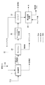
- FIG. 2 schematically shows the configuration around the drying apparatus 1 described above. That is, the carrier gas discharged from the drying device 1 passes through the cyclone 28, the carrier gas cooler 30 and the scrubber 32, and is recirculated to the drying device 1 through the carrier gas circulation path 22. .
- pulverized coal contained in the carrier gas discharged from the drying device 1 is removed.
- the pulverized coal removed by the cyclone 28 is guided to a bag filter (see reference numeral 34 in FIG. 1).
- water vapor contained in the carrier gas is condensed and removed as drain water.
- the drain water is guided to the liquid phase part of the scrubber 32.
- the scrubber 32 mercury contained in the carrier gas and pulverized coal that could not be removed by the cyclone 28 are removed. Most of the carrier gas processed by the scrubber 32 is guided to the drying apparatus 1 via the carrier gas circulation path 22. A part of the carrier gas is led to a combustion furnace (see reference numeral 42 in FIG. 1). The absorbing liquid (drainage) that adsorbs pulverized coal, mercury and the like by the scrubber 32 is guided to the wastewater treatment facility 40. In the wastewater treatment facility 40, after adding a chelating agent to the wastewater to agglomerate and enlarge mercury and the like, solid content such as pulverized coal and mercury and reclaimed water are separated by a sedimentation tank (not shown).
- the drying apparatus 1 operates in a temperature range (150 ° C. or higher and 200 ° C. or lower) below about 400 ° C. which is the evaporation temperature of mercury, a non-negligible amount of mercury or the like is generated. . Therefore, a scrubber 32 for treating the carrier gas discharged from the drying device 1 with the desorbed components desorbed from the coal when the drying device 1 dries the coal is provided. Thereby, the mercury etc. which generate
- the carrier gas By introducing the carrier gas after being processed by the scrubber 32 to the drying device 1 through the carrier gas circulation path 22, the carrier gas is circulated and reused. Thereby, the consumption of carrier gas can be reduced. For example, in the case of drying coal with a moisture content of 27.5 wt% or less using N 2 as a carrier gas, the N 2 consumption can be suppressed to 14% or less. If the carrier gas is circulated without removing the mercury or the like, the mercury or the like is concentrated in the drying apparatus 1, so that it is particularly effective to remove the mercury or the like with the scrubber 32.
- the pulverized coal accompanying the carrier gas was separated by the cyclone 28 provided on the upstream side of the scrubber 32, the pulverized coal was further separated by the scrubber 32. Thereby, it is possible to prevent the pulverized coal from being released to the atmosphere as much as possible.
Landscapes
- Chemical & Material Sciences (AREA)
- Engineering & Computer Science (AREA)
- Oil, Petroleum & Natural Gas (AREA)
- Organic Chemistry (AREA)
- General Engineering & Computer Science (AREA)
- Mechanical Engineering (AREA)
- Environmental & Geological Engineering (AREA)
- Life Sciences & Earth Sciences (AREA)
- Analytical Chemistry (AREA)
- Chemical Kinetics & Catalysis (AREA)
- General Chemical & Material Sciences (AREA)
- Materials Engineering (AREA)
- Combustion & Propulsion (AREA)
- Health & Medical Sciences (AREA)
- Geology (AREA)
- Geochemistry & Mineralogy (AREA)
- General Life Sciences & Earth Sciences (AREA)
- Physics & Mathematics (AREA)
- Thermal Sciences (AREA)
- Biomedical Technology (AREA)
- Sustainable Development (AREA)
- Molecular Biology (AREA)
- Solid Fuels And Fuel-Associated Substances (AREA)
- Coke Industry (AREA)
Abstract
Description
石炭を乾留する際の温度は300℃以上500℃以下とされており、水銀の蒸発温度が約400℃とされているため、同文献に記載されているように乾留装置での水銀系物質の発生を考慮することは技術的に妥当と言える。このような理解の下、乾留を行う前の乾燥装置は150℃以上200℃以下に加熱して石炭中の水分を除去するものであるため、水銀および/または水銀系物質の発生は無視できる程度に小さいものと考えられていた。
すなわち、本発明の一態様に係る石炭改質プラントは、石炭を乾留する前に石炭を加熱して乾燥させる乾燥装置と、前記乾燥装置によって石炭が乾燥される際に該石炭から脱離された脱離成分を伴って該乾燥装置から排出されたキャリアガスを処理するスクラバとを備えている。
乾燥装置には、石炭が乾燥される際に石炭から脱離された脱離成分を排出させるためにキャリアガスが流される。キャリアガスに伴って排出される脱離成分としては、水蒸気や微粉炭とされるが、本発明者等が鋭意検討した結果、無視できない量の水銀および/または水銀系物質が含まれていることが判明した。乾燥装置にて発生した水銀および/または水銀系物質は、スクラバによって除去されることになる。
水銀および/または水銀系物質を除去せずにキャリアガスを循環させると水銀および/または水銀系物質が乾燥装置内で濃縮されることになるので、スクラバによって水銀および/または水銀系物質を除去することは特に効果的となる。
乾燥工程では、石炭が乾燥される際に石炭から脱離された脱離成分を排出させるためにキャリアガスが流される。キャリアガスに伴って排出される脱離成分としては、水蒸気や微粉炭とされるが、本発明者等が鋭意検討した結果、無視できない量の水銀および/または水銀系物質が含まれていることが判明した。乾燥工程にて発生した水銀および/または水銀系物質は、キャリアガス処理工程においてスクラバによって除去されることになる。
図1には、本発明の一実施形態に係る石炭改質プラントが示されている。石炭改質プラントは、石炭を加熱させて乾燥させる乾燥装置(dryer)1と、乾燥装置1にて乾燥された乾燥炭を加熱して乾留する乾留装置(pyrolyzer)3と、乾留装置3にて乾留された乾留炭を冷却する冷却装置(quencher)5と、冷却装置5にて冷却された乾留炭を不活性化させる不活性化装置(finisher)7と、不活性化装置7によって不活性化された改質炭を所定形状に成形する成形装置(briquetter)9とを備えている。
スクラバ32の上方には、キャリアガス循環経路22の上流端が接続されており、キャリアガス循環経路22の途中位置にはブロワ36が設けられている。ブロワ36によってスクラバ32にて処理された後のキャリアガスが乾燥装置1へと戻される。また、図示されていないが、スクラバ32にて処理された後のキャリアガスの一部は、燃焼炉42へと導かれるようになっている。
回転内筒46と外筒48との間の空間には、燃焼炉42にて生成された燃焼ガスが燃焼ガス導入経路50を介して導かれるようになっている。これにより、回転内筒46内が350℃以上450℃以下(例えば400℃)に維持される。
燃焼ガス排出経路62の下流側は、バグフィルタ34に接続されている。バグフィルタ34にて燃焼灰等が除去された燃焼排ガスは、大気(ATM)へと放出される。
第1散水管79には、常温とされた工業用水が導かれ、乾留炭に対して水を散布することによって水を直接接触させて冷却する。第1散水管79は、第1円筒容器78内を移動する乾留炭の上流側(図1において左側)に設けられる。なお、第1散水管79に供給する水として、排水処理設備40にて分離された再生水を用いてもよい。
各第1冷却管80内には、50℃以上100℃未満(例えば約60℃)のボイラ給水が供給され、各第1冷却管80の外周に接触する乾留炭を間接的に冷却するようになっている。各第1冷却管80は、第1円筒容器78内を移動する乾留炭の下流側(図1において右側)に設けられ、第1散水管79によって冷却された後の乾留炭を水の凝縮温度以上である約150℃まで冷却するようになっている。
第2散水管82には、常温とされた工業用水が導かれ、乾留炭に対して水を散布することによって乾留炭の水分含有率を所望値(例えば8wt%)になるように調整する。第2散水管82は、第2円筒容器81の軸線方向の略全体にわたって設けられる。なお、第2散水管82に供給する水として、排水処理設備40にて分離された再生水を用いてもよい。
各第2冷却管83内には、常温とされた工業用水が導かれ、各第2冷却管83の外周に接触する乾留炭を間接的に冷却するようになっている。各第2冷却管83は、乾留炭を約50℃まで冷却するようになっている。なお、各第2冷却管83に供給する水として、排水処理設備40にて分離された再生水を用いてもよい。
不活性化装置7は、冷却装置5にて冷却された乾留炭を受け入れる第1不活性化器86と、第1不活性化器86からの乾留炭を受け入れる第2不活性化器88とを備えている。
第1不活性化器86内に供給された酸化用ガスは、第1不活性化器86内で、乾留によって生じた活性点(ラジカル)を酸化することで乾留炭を不活性化処理する。第1不活性化器86から排出された酸化用ガスは、微粉炭を伴いつつ第1酸化用ガス出口管91を通り第1ブロワ92へと導かれる。第1ブロワ92によって圧送された酸化用ガスは再び第1酸化用ガス供給経路90へと導かれ、再循環される。第1酸化用ガス供給経路90へと導かれずに、酸化用ガス排出管93へと導かれた酸化用ガスは、サイクロン94へと導かれる。サイクロン94へ導かれた酸化用ガスは、サイクロン94にて微粉炭等の固形分が分離された後に、バグフィルタ34へと導かれて大気(ATM)へと放出される。サイクロン94にて分離された微粉炭等の固形分は、混練機100へ送られる。
第2不活性化器88内に供給された酸化用ガスは、第2不活性化器88内で、第1不活性化器86にて不活性化した乾留炭を更に不活性化処理する。第2不活性化器88から排出された酸化用ガスは、微粉炭を伴いつつ第2酸化用ガス出口管96を通り第2ブロワ97へと導かれる。第2ブロワ97によって圧送された酸化用ガスは再び第2酸化用ガス供給経路95へと導かれ、再循環される。第2酸化用ガス供給経路95へと導かれずに、酸化用ガス排出管93へと導かれた酸化用ガスは、サイクロン94へと導かれて微粉炭等の固形分が分離された後に、バグフィルタ34へと導かれて大気へと放出される。
図2には、上述した乾燥装置1周りの構成が模式的に示されている。すなわち、乾燥装置1から排出されたキャリアガスは、サイクロン28、キャリアガス冷却器30及びスクラバ32を通り、キャリアガス循環経路22を介して乾燥装置1へと再循環される構成が示されている。
サイクロン28では、乾燥装置1から排出されたキャリアガスに含まれる微粉炭が除去される。サイクロン28で除去された微粉炭は、バグフィルタ(図1の符号34参照)へと導かれる。
キャリアガス冷却器30では、キャリアガスに含まれる水蒸気が凝縮されてドレン水として除去される。ドレン水は、スクラバ32の液相部へと導かれる。
スクラバ32では、キャリアガスに含まれる水銀等とサイクロン28で除去できなかった微粉炭が除去される。スクラバ32にて処理されたキャリアガスの大部分はキャリアガス循環経路22を介して乾燥装置1へと導かれる。また、キャリアガスの一部は燃焼炉(図1の符号42参照)へと導かれる。スクラバ32にて微粉炭及び水銀等を吸着した吸収液(排水)は、排水処理設備40へと導かれる。
排水処理設備40では、キレート剤を排水に投入して水銀等を凝集肥大化させた上で、図示しない沈降槽によって、微粉炭及び水銀等の固形分と、再生水とを分離する。
本発明者等は、水銀の蒸発温度である約400℃を下回る温度域(150℃以上200℃以下)で動作する乾燥装置1であっても無視できない量の水銀等が発生することを見出した。そこで、乾燥装置1によって石炭が乾燥される際に石炭から脱離された脱離成分を伴って乾燥装置1から排出されたキャリアガスを処理するスクラバ32を設けることとした。これにより、石炭の乾燥工程で発生した水銀等を除去することができる。また、大気への水銀の放出や、改質炭の水銀含有量を減少させることができる。
水銀等を除去せずにキャリアガスを循環させると水銀等が乾燥装置1内で濃縮されることになるので、スクラバ32によって水銀等を除去することは特に効果的となる。
3 乾留装置
5 冷却装置
7 不活性化装置
9 成形装置
10 改質前の石炭
12 石炭ホッパ
14 粉砕機
16 円筒容器
18 伝熱管
20 蒸気生成システム
22 キャリアガス循環経路
28 サイクロン
30 キャリアガス冷却器
32 スクラバ
34 バグフィルタ
40 排水処理設備
42 燃焼炉
46 回転内筒
48 外筒
50 燃焼ガス導入経路
74 第1冷却器
76 第2冷却器
78 第1円筒容器
79 第1散水管
80 第1冷却管
81 第2円筒容器
82 第2散水管
83 第2冷却管
86 第1不活性化器
88 第2不活性化器
100 混練機
104 改質炭
Claims (4)
- 石炭を乾留する前に石炭を加熱して乾燥させる乾燥装置と、
前記乾燥装置によって石炭が乾燥される際に該石炭から脱離された脱離成分を伴って該乾燥装置から排出されたキャリアガスを処理するスクラバと、
を備えている石炭改質プラント。 - 前記スクラバによって処理された後の前記キャリアガスを前記乾燥装置へと導くキャリアガス循環経路を備えている請求項1に記載の石炭改質プラント。
- 前記スクラバの上流側に設けられた集塵機を備えている請求項1に記載の石炭改質プラント。
- 石炭を乾留する前に石炭を加熱して乾燥させる乾燥工程と、
前記乾燥工程によって石炭が乾燥される際に該石炭から脱離された脱離成分を伴って該乾燥工程から排出されたキャリアガスをスクラバによって処理するキャリアガス処理工程と、
を備えている改質石炭の製造方法。
Priority Applications (2)
| Application Number | Priority Date | Filing Date | Title |
|---|---|---|---|
| JP2017504916A JP6426270B2 (ja) | 2015-03-09 | 2016-02-05 | 石炭改質プラント及び改質石炭の製造方法 |
| AU2016230473A AU2016230473B2 (en) | 2015-03-09 | 2016-02-05 | Coal upgrade plant and method for manufacturing upgraded coal |
Applications Claiming Priority (2)
| Application Number | Priority Date | Filing Date | Title |
|---|---|---|---|
| US14/641,780 US10151530B2 (en) | 2015-03-09 | 2015-03-09 | Coal upgrade plant and method for manufacturing upgraded coal |
| US14/641780 | 2015-03-09 |
Publications (1)
| Publication Number | Publication Date |
|---|---|
| WO2016143429A1 true WO2016143429A1 (ja) | 2016-09-15 |
Family
ID=56879352
Family Applications (1)
| Application Number | Title | Priority Date | Filing Date |
|---|---|---|---|
| PCT/JP2016/053482 Ceased WO2016143429A1 (ja) | 2015-03-09 | 2016-02-05 | 石炭改質プラント及び改質石炭の製造方法 |
Country Status (4)
| Country | Link |
|---|---|
| US (1) | US10151530B2 (ja) |
| JP (1) | JP6426270B2 (ja) |
| AU (1) | AU2016230473B2 (ja) |
| WO (1) | WO2016143429A1 (ja) |
Cited By (1)
| Publication number | Priority date | Publication date | Assignee | Title |
|---|---|---|---|---|
| CN109161392A (zh) * | 2018-09-19 | 2019-01-08 | 西安三瑞实业有限公司 | 一种带有内部除尘的外热式回转炉煤炭热解装置及方法 |
Families Citing this family (2)
| Publication number | Priority date | Publication date | Assignee | Title |
|---|---|---|---|---|
| CN107880970B (zh) * | 2017-11-14 | 2023-10-31 | 华北电力大学(保定) | 一种微波辐射式煤炭低温热解脱汞系统及使用方法 |
| US12410914B2 (en) * | 2020-08-12 | 2025-09-09 | Air Products And Chemicals, Inc. | System and method for combusting high-moisture fuel to generate steam |
Citations (3)
| Publication number | Priority date | Publication date | Assignee | Title |
|---|---|---|---|---|
| JPS61250098A (ja) * | 1985-04-26 | 1986-11-07 | ウエスチングハウス エレクトリック コ−ポレ−ション | 低級炭乾燥方法及び装置 |
| JPS62114033U (ja) * | 1985-12-31 | 1987-07-20 | ||
| JP2012215316A (ja) * | 2011-03-31 | 2012-11-08 | Mitsubishi Heavy Ind Ltd | 流動層乾燥装置、流動層乾燥設備および湿潤原料乾燥方法 |
Family Cites Families (23)
| Publication number | Priority date | Publication date | Assignee | Title |
|---|---|---|---|---|
| US4173530A (en) | 1974-01-14 | 1979-11-06 | Otisca Industries, Ltd. | Methods of and apparatus for cleaning coal |
| DE2659335C2 (de) | 1976-12-29 | 1985-10-24 | Bergwerksverband Gmbh | Betrieb einer Kohleerhitzungsanlage |
| US4421520A (en) | 1981-12-21 | 1983-12-20 | Atlantic Richfield Company | Reducing the tendency of dried coal to spontaneously ignite |
| US4497637A (en) * | 1982-11-22 | 1985-02-05 | Georgia Tech Research Institute | Thermochemical conversion of biomass to syngas via an entrained pyrolysis/gasification process |
| US4725337A (en) | 1984-12-03 | 1988-02-16 | Western Energy Company | Method for drying low rank coals |
| US4705533A (en) | 1986-04-04 | 1987-11-10 | Simmons John J | Utilization of low rank coal and peat |
| JPS63210192A (ja) | 1987-02-27 | 1988-08-31 | Mitsubishi Heavy Ind Ltd | 石炭の熱処理法 |
| US5322530A (en) | 1992-10-20 | 1994-06-21 | Western Research Institute | Process for clean-burning fuel from low-rank coal |
| US5423891A (en) * | 1993-05-06 | 1995-06-13 | Taylor; Robert A. | Method for direct gasification of solid waste materials |
| US5711769A (en) | 1995-09-08 | 1998-01-27 | Tek-Kol Partnership | Process for passivation of reactive coal char |
| JP3948447B2 (ja) | 2003-09-29 | 2007-07-25 | 栗田工業株式会社 | 石炭の自然発火防止方法 |
| JP2006096615A (ja) | 2004-09-29 | 2006-04-13 | Taiheiyo Cement Corp | セメントキルンの排ガスの処理方法 |
| JP4979538B2 (ja) * | 2007-10-16 | 2012-07-18 | 株式会社神戸製鋼所 | 間接加熱乾燥装置、被乾燥物の間接加熱乾燥方法、ならびに固形燃料の製造方法および製造装置 |
| JP2013108700A (ja) | 2011-11-22 | 2013-06-06 | Mitsubishi Heavy Ind Ltd | 流動層乾燥装置 |
| JP5511855B2 (ja) | 2012-01-06 | 2014-06-04 | 三菱重工業株式会社 | 石炭不活性化処理方法 |
| JP2013173832A (ja) | 2012-02-24 | 2013-09-05 | Mitsubishi Heavy Ind Ltd | 改質石炭製造設備 |
| JP5449479B2 (ja) * | 2012-08-06 | 2014-03-19 | 三菱重工業株式会社 | 石炭乾留装置及びこれを利用する改質石炭製造設備 |
| WO2014049587A1 (en) * | 2012-09-25 | 2014-04-03 | Pt Total Sinergy International | Device for upgrading solid organic materials |
| JP6015933B2 (ja) | 2012-12-14 | 2016-10-26 | 三菱重工業株式会社 | 石炭不活性化処理装置およびこれを利用する改質石炭製造設備 |
| CN103007614A (zh) | 2012-12-30 | 2013-04-03 | 陆汉克 | 高效节能带式压滤机 |
| JP2015030738A (ja) | 2013-07-31 | 2015-02-16 | 三菱重工業株式会社 | 改質石炭の製造方法 |
| JP6245743B2 (ja) | 2013-12-06 | 2017-12-20 | 三菱重工業株式会社 | 石炭不活性化処理装置 |
| US9663423B2 (en) | 2014-10-27 | 2017-05-30 | Uop Llc | Methods and apparatuses for reforming of hydrocarbons including recovery of products using an absorption zone and a pressure swing adsorption zone |
-
2015
- 2015-03-09 US US14/641,780 patent/US10151530B2/en active Active
-
2016
- 2016-02-05 AU AU2016230473A patent/AU2016230473B2/en not_active Ceased
- 2016-02-05 JP JP2017504916A patent/JP6426270B2/ja not_active Expired - Fee Related
- 2016-02-05 WO PCT/JP2016/053482 patent/WO2016143429A1/ja not_active Ceased
Patent Citations (3)
| Publication number | Priority date | Publication date | Assignee | Title |
|---|---|---|---|---|
| JPS61250098A (ja) * | 1985-04-26 | 1986-11-07 | ウエスチングハウス エレクトリック コ−ポレ−ション | 低級炭乾燥方法及び装置 |
| JPS62114033U (ja) * | 1985-12-31 | 1987-07-20 | ||
| JP2012215316A (ja) * | 2011-03-31 | 2012-11-08 | Mitsubishi Heavy Ind Ltd | 流動層乾燥装置、流動層乾燥設備および湿潤原料乾燥方法 |
Cited By (2)
| Publication number | Priority date | Publication date | Assignee | Title |
|---|---|---|---|---|
| CN109161392A (zh) * | 2018-09-19 | 2019-01-08 | 西安三瑞实业有限公司 | 一种带有内部除尘的外热式回转炉煤炭热解装置及方法 |
| CN109161392B (zh) * | 2018-09-19 | 2020-08-11 | 西安三瑞实业有限公司 | 一种带有内部除尘的外热式回转炉煤炭热解装置及方法 |
Also Published As
| Publication number | Publication date |
|---|---|
| US20160265845A1 (en) | 2016-09-15 |
| AU2016230473B2 (en) | 2018-11-29 |
| AU2016230473A1 (en) | 2017-07-13 |
| JPWO2016143429A1 (ja) | 2017-11-30 |
| JP6426270B2 (ja) | 2018-11-21 |
| US10151530B2 (en) | 2018-12-11 |
Similar Documents
| Publication | Publication Date | Title |
|---|---|---|
| JP6469840B2 (ja) | 石炭改質プラントおよび改質石炭の製造方法 | |
| EP3575382B1 (en) | System for drying lignite and method for drying lignite | |
| JP5893974B2 (ja) | 汚泥の乾燥システム | |
| US8349036B2 (en) | Systems and method for heating and drying solid feedstock in a gasification system | |
| AU2018282459B2 (en) | Dry-distilled coal cooling device, coal upgrading plant, and dry-distilled coal cooling method | |
| JP6426271B2 (ja) | 石炭改質プラントならびに改質石炭の製造方法 | |
| JP6502532B2 (ja) | 半炭化バイオマスの冷却方法 | |
| JP6426270B2 (ja) | 石炭改質プラント及び改質石炭の製造方法 | |
| JP2022508771A (ja) | 炭素質材料を処理する方法およびそのための装置 | |
| JP5851884B2 (ja) | 流動層乾燥装置、ガス化複合発電設備および乾燥方法 | |
| CN112368236A (zh) | 以生物质作为原料的氢气制造方法 | |
| JP2004361013A (ja) | 水分を含む廃棄物の乾燥方法および乾燥システム | |
| JP6270206B2 (ja) | 有機性廃棄物の処理装置、および有機性廃棄物の処理方法 | |
| WO2016143431A1 (ja) | 乾留炭不活性化装置および石炭改質プラントならびに不活性化乾留炭の製造方法 | |
| JP5714142B2 (ja) | 石炭乾留装置 | |
| BE1020400A5 (nl) | Nieuwe werkwijze en inrichting voor het regenereren van afgewerkt, koolstofhoudend adsorbeermiddel. | |
| CN120141098A (zh) | 一种回转式煤泥间接干燥机的蒸发湿气重复利用系统及方法 | |
| CN114270101A (zh) | 混合式锅炉干燥器和方法 |
Legal Events
| Date | Code | Title | Description |
|---|---|---|---|
| 121 | Ep: the epo has been informed by wipo that ep was designated in this application |
Ref document number: 16761401 Country of ref document: EP Kind code of ref document: A1 |
|
| ENP | Entry into the national phase |
Ref document number: 2016230473 Country of ref document: AU Date of ref document: 20160205 Kind code of ref document: A |
|
| ENP | Entry into the national phase |
Ref document number: 2017504916 Country of ref document: JP Kind code of ref document: A |
|
| NENP | Non-entry into the national phase |
Ref country code: DE |
|
| 122 | Ep: pct application non-entry in european phase |
Ref document number: 16761401 Country of ref document: EP Kind code of ref document: A1 |