WO2016143166A1 - 燃料噴射弁 - Google Patents
燃料噴射弁 Download PDFInfo
- Publication number
- WO2016143166A1 WO2016143166A1 PCT/JP2015/075990 JP2015075990W WO2016143166A1 WO 2016143166 A1 WO2016143166 A1 WO 2016143166A1 JP 2015075990 W JP2015075990 W JP 2015075990W WO 2016143166 A1 WO2016143166 A1 WO 2016143166A1
- Authority
- WO
- WIPO (PCT)
- Prior art keywords
- nozzle hole
- fuel
- center
- nozzle
- side opening
- Prior art date
- Legal status (The legal status is an assumption and is not a legal conclusion. Google has not performed a legal analysis and makes no representation as to the accuracy of the status listed.)
- Ceased
Links
Images



Classifications
-
- F—MECHANICAL ENGINEERING; LIGHTING; HEATING; WEAPONS; BLASTING
- F02—COMBUSTION ENGINES; HOT-GAS OR COMBUSTION-PRODUCT ENGINE PLANTS
- F02M—SUPPLYING COMBUSTION ENGINES IN GENERAL WITH COMBUSTIBLE MIXTURES OR CONSTITUENTS THEREOF
- F02M61/00—Fuel-injectors not provided for in groups F02M39/00 - F02M57/00 or F02M67/00
- F02M61/16—Details not provided for in, or of interest apart from, the apparatus of groups F02M61/02 - F02M61/14
- F02M61/18—Injection nozzles, e.g. having valve seats; Details of valve member seated ends, not otherwise provided for
- F02M61/1806—Injection nozzles, e.g. having valve seats; Details of valve member seated ends, not otherwise provided for characterised by the arrangement of discharge orifices, e.g. orientation or size
- F02M61/1813—Discharge orifices having different orientations with respect to valve member direction of movement, e.g. orientations being such that fuel jets emerging from discharge orifices collide with each other
-
- F—MECHANICAL ENGINEERING; LIGHTING; HEATING; WEAPONS; BLASTING
- F02—COMBUSTION ENGINES; HOT-GAS OR COMBUSTION-PRODUCT ENGINE PLANTS
- F02M—SUPPLYING COMBUSTION ENGINES IN GENERAL WITH COMBUSTIBLE MIXTURES OR CONSTITUENTS THEREOF
- F02M61/00—Fuel-injectors not provided for in groups F02M39/00 - F02M57/00 or F02M67/00
- F02M61/16—Details not provided for in, or of interest apart from, the apparatus of groups F02M61/02 - F02M61/14
- F02M61/18—Injection nozzles, e.g. having valve seats; Details of valve member seated ends, not otherwise provided for
- F02M61/1806—Injection nozzles, e.g. having valve seats; Details of valve member seated ends, not otherwise provided for characterised by the arrangement of discharge orifices, e.g. orientation or size
- F02M61/1846—Dimensional characteristics of discharge orifices
-
- F—MECHANICAL ENGINEERING; LIGHTING; HEATING; WEAPONS; BLASTING
- F02—COMBUSTION ENGINES; HOT-GAS OR COMBUSTION-PRODUCT ENGINE PLANTS
- F02M—SUPPLYING COMBUSTION ENGINES IN GENERAL WITH COMBUSTIBLE MIXTURES OR CONSTITUENTS THEREOF
- F02M51/00—Fuel-injection apparatus characterised by being operated electrically
- F02M51/06—Injectors peculiar thereto with means directly operating the valve needle
- F02M51/061—Injectors peculiar thereto with means directly operating the valve needle using electromagnetic operating means
- F02M51/0625—Injectors peculiar thereto with means directly operating the valve needle using electromagnetic operating means characterised by arrangement of mobile armatures
- F02M51/0664—Injectors peculiar thereto with means directly operating the valve needle using electromagnetic operating means characterised by arrangement of mobile armatures having a cylindrically or partly cylindrically shaped armature, e.g. entering the winding; having a plate-shaped or undulated armature entering the winding
- F02M51/0671—Injectors peculiar thereto with means directly operating the valve needle using electromagnetic operating means characterised by arrangement of mobile armatures having a cylindrically or partly cylindrically shaped armature, e.g. entering the winding; having a plate-shaped or undulated armature entering the winding the armature having an elongated valve body attached thereto
- F02M51/0682—Injectors peculiar thereto with means directly operating the valve needle using electromagnetic operating means characterised by arrangement of mobile armatures having a cylindrically or partly cylindrically shaped armature, e.g. entering the winding; having a plate-shaped or undulated armature entering the winding the armature having an elongated valve body attached thereto the body being hollow and its interior communicating with the fuel flow
Definitions
- the present invention is a fuel injection valve used in an internal combustion engine such as a gasoline engine, wherein the valve body abuts on the valve seat to prevent fuel leakage, and the valve body performs injection by moving away from the valve seat.
- the present invention relates to a fuel injection valve.
- Patent Document 1 discloses that a divergent nozzle hole is arranged downstream and outward, and the farthest part from the central axis of the upstream end face of the nozzle hole and the center of the downstream end face By making the relationship between the distance x from the nearest part from the shaft and the length L of the central axis side wall surface of the nozzle hole to x / L ⁇ 0.05, atomization of the fuel spray and control of the injection direction An invention of a fuel injection nozzle that balances performance is disclosed.
- each nozzle hole is formed so as to be away from the central axis of the nozzle plate in the fuel injection direction, and the fuel flowing into the nozzle hole is formed in the inner periphery of the nozzle hole.
- An invention of a fluid injection nozzle that atomizes fuel spray by being guided by a surface and expanding in contact with the inner peripheral surface of the injection hole to form a liquid film and being injected from the injection hole is disclosed.
- Patent Document 3 18 nozzle holes formed in a nozzle plate are divided into two groups, and a spray flow in two directions is formed from the two nozzle hole groups.
- An invention of a fuel injection valve is disclosed.
- the spray flow is a virtual straight line obtained by extending the flow path axis of each nozzle hole in the fuel injection direction, and a virtual plane that is separated from the nozzle hole plate by a predetermined distance in the fuel injection direction and orthogonal to the injection axis of the nozzle hole plate.
- a spray flow is formed such that the intersection point with is located on the apex of a regular octagon.
- Patent Document 1 discloses a method of promoting atomization by forming a fuel injection from a fuel injection hole into a horseshoe-shaped jet by utilizing flow separation by using a diverging nozzle hole.
- Patent Document 2 discloses a method of controlling the injection direction by setting the optimal nozzle hole size.
- Patent Document 3 discloses a method of reducing the deviation of the injection amount by setting the inclination angle of a plurality of injection holes.
- the methods disclosed in any of the documents are inclined so that the central axis of the nozzle hole is separated toward the downstream with respect to the central axis of the nozzle plate for atomization of the spray. The spray spreads toward the outer edge side of the nozzle plate in the inclined direction.
- the fuel that has flowed into the nozzle hole collides with the wall surface of the nozzle hole, and a flow having a large velocity component is induced in a plane perpendicular to the central axis of the nozzle hole. Due to the velocity component in the radial direction of the induced flow, the fuel tends to spread downstream of the nozzle hole, so that atomization is promoted. At this time, a larger collision force can be obtained as the inclination angle of the nozzle hole with respect to the direction in which the fuel flows is larger. However, in order to narrow the spray angle, it is necessary to reduce the inclination of the nozzle hole. When the inclination of the nozzle hole is reduced, the collision force is reduced and the particle size is deteriorated. Become.
- An object of the present invention is to provide a fuel injection valve capable of achieving sufficient atomization even when the spray angle is narrow.
- a fuel injection valve of the present invention includes a seat member having a valve seat, a valve body that is closed by being seated on the valve seat and is opened by being separated from the valve seat, A fuel passage portion disposed downstream of the valve seat; a fuel diffusion chamber disposed downstream of the fuel passage portion; and a plurality of injection holes for injecting fuel in the fuel diffusion chamber to the outside.
- a fuel injection valve for flowing the fuel that has flowed from the fuel passage portion into the fuel diffusion chamber so as to diffuse from the center side to the outer peripheral side of the fuel diffusion chamber and into the nozzle hole;
- a first nozzle hole and a first nozzle hole spaced apart from at least the circumferential direction of the fuel diffusion chamber with respect to the first nozzle hole, and adjacent to both sides of the first nozzle hole in the circumferential direction.
- the distance between the center of the inlet side opening of the first nozzle hole and the center of the inlet side opening of the second nozzle hole is such that the center of the inlet side opening of the first nozzle hole and the inlet side of the third nozzle hole If greater than the distance to the center of the opening,
- the first nozzle hole is
- the outlet side opening includes a tangent line that is centered on the center of the fuel diffusion chamber and is in contact with an arrangement circle passing through the center of the inlet side opening; and is disposed within a range of the fuel diffusion chamber on the center side with respect to the tangent line; and Including a line segment passing through the center of the fuel diffusion chamber and the center of the inlet side opening, and arranged within a range on the second nozzle hole side with respect to the line segment,
- the tilt direction is set.
- the fuel injection valve 1 shown in FIG. 1 is an example of a fuel injection valve for a port injection type gasoline engine.
- the effect of the present invention is that the fuel injection valve for a direct injection gasoline engine in a cylinder or a piezo is used. This is also effective in a fuel injection valve driven by an element or a magnetostrictive element.
- FIG. 1 is a sectional view showing an embodiment of a fuel injection valve according to the present invention.
- the basic configuration of the fuel injection valve 1 shown in FIG. 1 is also applied to second to fourth embodiments described later.
- the vertical direction is defined based on FIG. This vertical direction does not mean the vertical direction when the fuel injection valve 1 is mounted on the engine.
- a fuel injection valve 1 supplies fuel to an internal combustion engine used as, for example, an automobile engine.
- the casing 2 is formed in an elongated cylindrical shape by pressing or cutting.
- the casing 2 has a stepped structure in which a thin part, a thick part, a small diameter part, and a large diameter part are integrally formed.
- the material is a ferritic stainless steel material plus a flexible material such as titanium, and has magnetic properties.
- a fuel supply port 2 a is provided at one end of the casing 2, and a nozzle body 5 is provided at the other end.
- a nozzle plate 6 is fixed to the lower end surface (tip surface) of the nozzle body 5.
- the nozzle plate 6 is provided with a plurality of through holes 7 (see FIGS. 2 and 3).
- the plurality of through holes 7 constitute fuel injection holes 7 (hereinafter referred to as injection holes) for injecting fuel.
- the outer side of the casing 2 is provided with an electromagnetic coil 14 and a magnetic material yoke 16 surrounding the electromagnetic coil 14.
- a core 15, an anchor 4, a valve body 3, a nozzle body 5, and a nozzle plate 6 are provided inside the casing 2.
- the core 15 is disposed so as to be positioned inside the electromagnetic coil 14 after being inserted into the casing 2.
- the anchor 4 faces the end face (lower end face) on the front end side of the core 15 via a gap, and is attached so as to be movable in the direction of the central axis 100 of the fuel injection valve.
- the anchor 4 is manufactured by injection molding metal powder made of a magnetic material by a method such as MIM (Metal Injection Molding).
- the valve body 3 is a hollow member that is held by the anchor 4 and extends in the axial direction.
- a spherical body portion 3 ⁇ / b> A is provided at the distal end portion of the valve body 3.
- the nozzle body 5 is fixed to the casing 2 on the distal end side (lower end side) of the valve body 3.
- the nozzle body 5 is provided with a pedestal (valve seat) to which the spherical body portion 3 ⁇ / b> A provided at the distal end portion of the valve body 3 is separated.
- the nozzle plate 6 is disposed on the tip surface side of the nozzle body 5.
- the nozzle plate 6 is provided with a plurality of nozzle holes 7 formed so as to penetrate in the thickness direction.
- the nozzle plate 6 is joined to the surface that contacts the nozzle body 5 by welding.
- the nozzle body 5 is joined to the casing 2 by welding.
- a spring 12 as an elastic member is disposed inside a core 15.
- the spring 12 applies a force (urging force) for pressing the tip of the valve body 3 against the nozzle body 5.
- a spring adjuster 13 that adjusts the pressing force of the spring 12 is disposed continuously to the upper end of the spring 12.
- a filter 20 is disposed at the fuel supply port 2a. The filter 20 removes foreign matters contained in the fuel. Further, an O-ring 21 for sealing the supplied fuel is attached to the outer periphery of the fuel supply port 2a.
- the resin cover 22 is provided so as to cover the casing 2 and the yoke 16 by means such as a resin mold.
- a connector 23 for supplying power to the electromagnetic coil 14 is integrally formed on the resin cover 22.
- the protector 24 is a cylindrical member made of, for example, a resin material, provided at the tip of the fuel injection valve 1.
- the protector 24 is a member that covers the outer periphery of the front end portion of the casing 2.
- the protector 24 has a protruding portion 24A that protrudes outward in the radial direction.
- the projecting portion 24 ⁇ / b> A and the yoke 16 form an annular groove that holds the O-ring 25 below the coil 14.
- the O-ring 25 is attached to the outer periphery on the front end side of the casing 2.
- the O-ring 25 is disposed between the yoke 16 and the protector 24 so as not to be pulled out.
- the O-ring 25 seals the space between the intake pipe and the fuel injection valve 1 when, for example, the front end side of the casing 2 is attached to an attachment portion (not shown) provided in the intake pipe of the internal combustion engine. .
- the fuel injection valve 1 is urged by the pressing force of the spring 12 when the electromagnetic coil 14 is in a non-energized state, and the tip of the valve body 3 (sphere part 3A) is in close contact with the nozzle body 5.
- a gap that is, a fuel passage is not formed between the valve body 3 and the nozzle body 5, so that the fuel flowing in from the fuel supply port 2a remains inside the casing 2. That is, the valve body 3 is closed.
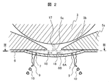
- FIG. 2 is an enlarged cross-sectional view of the vicinity of the tip of the valve body of the fuel injection valve according to the first embodiment of the present invention.
- the main parts according to the present invention will be briefly described with reference to FIG.
- the valve body 3 uses a ball valve.
- a ball for example, a JIS standard ball bearing steel ball is used. This ball has a high roundness and is mirror-finished, so that it is suitable for enhancing the sheet property and is low in cost due to mass production.
- a ball having a diameter of about 3 to 4 mm is used. The reason is to reduce the weight because it functions as a movable valve.
- the angle of the inclined surface including the sheet position in close contact with the valve body 3 is about 90 ° (80 ° to 100 °).
- This inclination angle is an optimum angle for polishing the vicinity of the seat position and increasing the roundness (the grinding machine can be used in the best condition), and maintains the above-mentioned seat property with the valve body 3 extremely high. It can be done.
- the hardness of the nozzle body 5 having the inclined surface 5b including the sheet position is increased by quenching.
- unnecessary magnetism is removed from the nozzle body 5 by demagnetization treatment. With such a valve body configuration, it is possible to control the injection amount without fuel leakage. Moreover, the valve body structure excellent in cost performance can be provided.
- the nozzle plate 6 is extruded by punching in the manufacturing process for forming the convex surface 6A in order to form a downward convex shape.
- the convex surface 6A is formed of a curved surface portion that is formed in a protruding shape downward (outward of the fuel injection valve).
- valve body 3 When the fuel injection valve 1 is in a closed state, the valve body 3 is in contact with a valve seat surface 5b formed of a conical surface provided on the seat member 5a, thereby maintaining a fuel seal. At this time, the contact portion on the valve body 3 side is formed by a spherical surface, and the contact between the conical valve seat surface 5b and the spherical surface is in a substantially line contact state.
- the valve body 3 is lifted and a gap is formed between the valve body 3 and the seat member 5a, the fuel flows out of the gap, and the opening 5c of the seat member 5a opens from the direction of the arrow 17 to the upper surface of the nozzle plate 6. collide.
- the gas flows from the center of the nozzle plate 6 along the surface of the nozzle plate 6 as indicated by an arrow 18.
- the fuel forms a liquid film 9 after passing through the nozzle hole 7.
- the liquid film 9 is split into droplets 10 due to instability due to surface tension waves and shearing force with air, and fuel atomization is achieved.
- the opening 5c introduces fuel from a seat portion formed between the valve body 3 and the valve seat surface into a fuel chamber (fuel diffusion chamber) 6B formed inside the convex surface 6A of the nozzle plate 6. Part (fuel introduction hole).
- the fuel chamber 6B flows the fuel flowing in from the fuel passage portion 5c so as to diffuse from the center side to the outer peripheral side, and flows into the nozzle hole 7.
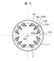
- FIG. 3 is a view of the nozzle plate of the fuel injection valve according to the first embodiment of the present invention as viewed from the valve body side.
- FIG. 3 is a III-III cross section of FIG.
- Arrow 11 indicates the tilt direction of the nozzle hole 7.
- the arrangement circle 101 is a circle that passes through the center 105 ⁇ / b> A of the inlet-side opening 105 of the nozzle hole 7 and that is centered on the central axis 102 of the nozzle plate 6.
- the central axis 102 of the nozzle plate 6 coincides with the central axis 100 of the fuel injection valve. Further, the central axis 102 of the nozzle plate 6 passes through the center of the fuel diffusion chamber 6B.
- the inclination direction of each nozzle hole 7 is set inwardly downward. That is, the inclination direction of each nozzle hole 7 is set so that the arrow 11 faces the inside of the arrangement circle 101.
- the inclination direction of each nozzle hole 7 is drawn on both sides of the center 105A of the inlet-side opening 105 of the nozzle hole 7 on the projection (FIG. 3) projected onto a plane perpendicular to the central axis 102. It is set so as to go on the center axis 102 side with respect to the tangent line 104 including the tangent line 104.
- the center 106 ⁇ / b> A of the outlet side opening 106 of the nozzle hole 7 includes the tangent line 104 and is located in a range on the central axis 102 side with respect to the tangent line 104. At this time, the center 106 ⁇ / b> A of the outlet side opening 106 of the nozzle hole 7 is provided at a position shifted from the center 105 ⁇ / b> A of the inlet side opening 105.
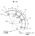
- FIG. 4A is an explanatory diagram about the inclination direction of the nozzle holes installed in the nozzle plate according to the first embodiment of the present invention.
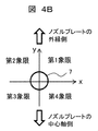
- FIG. 4B is an explanatory diagram for defining a quadrant in an arbitrary nozzle hole according to the first embodiment of the present invention.
- 4A is an enlarged view of a plurality of nozzle holes 7a to 7e installed in the nozzle plate 6.
- FIG. 4A and 4B are projection views in which the nozzle plate 6 is projected onto a plane perpendicular to the central axis 102.
- Each nozzle hole 7 (7a to 7e) is installed at an interval between adjacent nozzle holes L1 to L4.
- the nozzle hole 7a inclines the nozzle hole in a range ⁇ a inside the nozzle hole arrangement circle 101 (third quadrant and fourth quadrant with reference to the nozzle hole 7a).
- the outer edge side of the nozzle plate 6 is defined as the + y direction, and the central axis 102 side of the nozzle plate 6 is defined as the ⁇ y direction. Defined by the first quadrant, the second quadrant, the third quadrant, and the fourth quadrant.
- L4 is L1 ⁇ L4.
- the nozzle hole 7b inclines the nozzle hole in the range ⁇ b in the quadrant (L4 quadrant) on the inner side of the nozzle hole arrangement circle 101 and having a long distance between the nozzle holes.
- L3 is L2 ⁇ L3.
- the nozzle hole 7c inclines the nozzle hole in the range ⁇ c in the quadrant (third quadrant) on the L3 side where the distance between the nozzle holes is longer and the distance between the nozzle holes 101 is longer.
- the tangent line 104 on the third quadrant side is included. Further, it includes a line segment (y-axis) 107 connecting the center 105A of the inlet-side opening 105 of the nozzle hole 7b and the central axis 102.
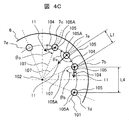
- FIG. 4C is an explanatory view of a specific example in which the nozzle hole is inclined according to the first embodiment of the present invention.
- FIG. 4C is a projection view in which the nozzle plate 6 is projected on a plane perpendicular to the central axis 102.
- the arrangement of the nozzle holes 7 (7a to 7c) in FIG. 4C is the same as the arrangement of the nozzle holes 7 (7a to 7c) in FIG. 4A.
- the arrow 11 in the figure indicates the inclination direction of the nozzle hole.
- the start end of the arrow 11 is located at the center 105A of the inlet side opening 105 of the nozzle hole 7 (7a to 7c), and the end (arrow tip) is located at the center 106A (see FIG. 3) of the outlet side opening 106 of the nozzle hole 7. Indicates direction.
- the nozzle hole 7a is inclined within the range ⁇ a of the third and fourth quadrants with reference to the nozzle hole 7a.
- the arrow 11 of the nozzle hole 7a starts from the center 105A of the inlet-side opening 105 of the nozzle hole 7a.
- the end of the arrow 11 (the tip of the arrow) is located within the third and fourth quadrants.
- the range of the third and fourth quadrants includes the tangent line 104 drawn on both sides of the center 105A of the inlet side opening 105 of the injection hole 7a, and is a range on the central axis 102 side with respect to the tangent line 104. That is, the center 106A (see FIG. 3) of the outlet side opening 106 of the nozzle hole 7a includes the tangent line 104 and is located in a range on the central axis 102 side with respect to the tangent line 104.
- the nozzle hole 7a is inclined toward the central axis 102.
- the arrow 11 overlaps the line segment (y axis) 107 connecting the center 105A of the entrance side opening 105 and the center axis 102.
- the injection hole 7b is inclined within a range ⁇ b in the fourth quadrant with respect to the injection hole 7b.
- the arrow 11 of the nozzle hole 7b starts from the center 105A of the inlet side opening 105 of the nozzle hole 7b.
- the end of the arrow 11 is located within the range of the fourth quadrant.
- the range of the fourth quadrant is a line segment (y) connecting the tangent line 104 drawn from the center 105A of the inlet side opening 105 of the nozzle hole 7b to the fourth quadrant side and the center 105A of the inlet side opening 105 and the central axis 102.
- the range of the fourth quadrant is a range on the nozzle hole 7d side (the side opposite to the nozzle hole 7a) with respect to the line segment 107.
- the center 106A (see FIG. 3) of the outlet side opening 106 of the nozzle hole 7b is located within the range of the fourth quadrant.
- the injection hole 7c is inclined within the range ⁇ c of the third quadrant with reference to the injection hole 7c.
- the arrow 11 of the nozzle hole 7c starts from the center 105A of the inlet-side opening 105 of the nozzle hole 7c.
- the end of the arrow 11 is located within the range of the third quadrant.
- the range of the third quadrant is a line segment (y) connecting the tangent line 104 drawn from the center 105A of the inlet side opening 105 of the nozzle hole 7c to the third quadrant side and the center 105A of the inlet side opening 105 and the central axis 102.
- the range of the third quadrant is a range on the nozzle hole 7e side (the side opposite to the nozzle hole 7a) with respect to the line segment 107.
- the center 106A (see FIG. 3) of the outlet side opening 106 of the nozzle hole 7c is located within the range of the third quadrant.
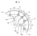
- FIG. 5 is a diagram illustrating a fuel flow field inside the nozzle plate according to the first embodiment of the present invention.
- FIG. 6 is an explanatory diagram of a fuel atomization mechanism in the present invention.
- FIG. 5 is a projection view in which the nozzle plate 6 is projected on a plane perpendicular to the central axis 102.
- FIG. 5 shows the fuel flow directions 18a, 18b, 18c, 18d, and 18e, which are mainstreams of the nozzle holes 7a, 7b, 7c, 7d, and 7e, inside the nozzle plate (in the fuel chamber 6B) by arrows.
- the main fuel flows 18b and 18c with respect to the nozzle holes 7b and 7c are emitted from the central axis 102 of the nozzle plate 6 toward the center of the nozzle hole. It flows in obliquely from the L3 and L4 sides with respect to the direction.
- FIG. 6 is an enlarged view (sectional view) of the vicinity of the nozzle hole 7.
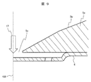
- the fuel flow 17 at the opening 5 c of the fuel passage portion collides with the upper surface of the nozzle plate 6 and becomes a fast flow 18 in the main flow direction along the wall surface of the nozzle plate 6.
- the injection hole 7 is inclined in a direction opposite to the main flow direction, the fuel 103 a flowing into the injection hole 7 collides with the wall surface 72 of the injection hole and is in a plane perpendicular to the central axis 73 of the injection hole 7.
- a flow 103b having a large velocity component is induced.
- the nozzle hole 7 is inclined from the nozzle hole inlet to the nozzle hole outlet so as to be directed toward the main flow direction 18 of the fuel, that is, toward the central axis 102 of the nozzle plate 6. The spread of the spray to the outer edge side can be suppressed, and the spray angle can be reduced.
- the injection hole 7 a is preferably inclined in the range ⁇ a of the third and fourth quadrants not including the tangent line 104 and inside the arrangement circle 101. . That is, it is preferable to arrange the nozzle hole 7a so that the center 106A of the outlet side opening 106 is located inside the arrangement circle 101 on FIG. 4C. More preferably, the nozzle hole 7a may be inclined so that the arrow 11 overlaps the line segment 107 on FIG. 4C.
- the nozzle hole 7 b is inclined on the tangent line 104 and in the range ⁇ b of the fourth quadrant not including the line segment 107 and inside the arrangement circle 101. That is, the nozzle hole 7b is located within the range where the center 106A of the outlet opening 106 is inside the arrangement circle 101 and on the nozzle hole 7d side (opposite to the nozzle hole 7a) in FIG. 4C. It is preferable to incline so that it may be located in.
- the injection hole 7c is inclined on the tangent line 104 and in the third quadrant range ⁇ c not including the line segment 107 and inside the arrangement circle 101. That is, the nozzle hole 7c is located within the range where the center 106A of the outlet opening 106 is inside the arrangement circle 101 and the nozzle hole 7e side (opposite to the nozzle hole 7a) with respect to the line segment 107 in FIG. 4C. It is preferable to incline so that it may be located in.
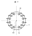
- FIG. 7 is a view of a nozzle plate of a fuel injection valve, which is a comparative example with the present invention, as viewed from the valve body side.
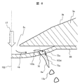
- FIG. 8 is an explanatory diagram of the flow field in the vicinity of the injection hole of the fuel injection valve, which is a comparative example with the present invention.
- the nozzle hole 70 was inclined in a direction away from the central axis 102 of the nozzle plate 60 from the nozzle hole inlet to the nozzle hole outlet in order to avoid the interference of the spray.
- the inclination direction of the injection hole 70 is not optimal with respect to the main flow direction 18, and the collision force of the fuel flow 103d flowing into the injection hole 70 with respect to the injection hole wall surface becomes weak.
- the flow velocity component in the in-plane direction perpendicular to the central axis 73a of the nozzle hole 70 is reduced, and the velocity component in the direction of the central axis 73a is increased in the nozzle hole 70 as in the flow 103d.
- the main flow direction of the fuel is defined by the distance between the nozzle holes, and the optimum inclination range of the nozzle hole is defined according to the distance between the nozzle holes.
- FIG. 9 is an enlarged sectional view of the vicinity of the injection hole of the fuel injection valve according to the second embodiment of the present invention.
- Those assigned the same numbers as those used in the description of the first embodiment have the same or equivalent functions as those of the first embodiment, and the description thereof will be omitted.
- FIG. 9 is different from FIG. 2 of the first embodiment in that the nozzle plate 6 is formed in a planar shape instead of a curved shape. Also in this embodiment, the effects described in the first embodiment can be obtained.
- FIG. 10 is a view of the nozzle plate of the fuel injection valve according to the third embodiment of the present invention as viewed from the valve body side.
- Those assigned the same numbers as those used in the description of the first embodiment have the same or equivalent functions as those of the first embodiment, and the description thereof will be omitted.
- a plurality of nozzle holes are arranged on two arrangement circles 101a and 101b.
- the inclination direction 11 of the nozzle hole 7 is determined between the nozzle holes 7 arranged on the two arrangement circles 101a and 101b. That is, the inclination direction 11 of the nozzle hole is determined based on the quadrant of each nozzle hole (see FIG. 4B) from the distance between a certain nozzle hole and the two nozzle holes closest to the nozzle hole. Thereby, the same effect as Example 1 can be acquired.
- the inclination of the nozzle hole 7f is based on the distance between the nozzle holes 7h arranged on the arrangement circle 101a, the nozzle holes 7f arranged on the arrangement circle 101b, and the nozzle holes 7g. Determine the direction.
- the distance L6 between the nozzle hole 7f and the nozzle hole 7g and the distance L5 between the nozzle hole 7f and the nozzle hole 7h are in a relationship of L6> L5.
- the nozzle hole 7f is inclined within the range ⁇ b of the fourth quadrant with reference to the nozzle hole 7f, similarly to the nozzle hole 7b described in the first embodiment.
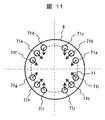
- FIG. 11 is a view of the nozzle plate of the fuel injection valve according to the fourth embodiment of the present invention as seen from the valve body side.
- the effect of applying the nozzle hole inclination described in the first embodiment to only some of the nozzle holes will be described.
- Those assigned the same numbers as those used in the description of the first embodiment have the same or equivalent functions as those of the first embodiment, and the description thereof will be omitted.
- the fuel injection valve of the present embodiment has a plurality of injection holes 71 (71a to 71l) in the nozzle plate 6.
- the inclination direction of some of the nozzle holes 71c, 71d, 71i, 71j is the optimum inclination direction described in the first embodiment. Set in different directions.
- the inclination directions of the nozzle holes 71a, 71b, 71e, 71f, 71g, 71h, 71k, and 71l are set to the inclination directions described in the first embodiment.
- the optimum inclination direction for atomization is in the third quadrant, but the inclination direction is set in the fourth quadrant in order to obtain a target spray shape.
- the optimum inclination direction for atomization is in the fourth quadrant, but the inclination direction is set in the third quadrant in order to obtain a target spray shape.
- the tilt direction described in the first embodiment is set to only some of the nozzle holes 71a, 71b, 71e, 71f, 71g, 71h, 71k, 71l, some of the nozzle holes 71a, 71b, 71e. , 71f, 71g, 71h, 71k, 71l, the effect described in the first embodiment can be obtained.
- the fuel injection valve of the present invention includes a seat member 15a having a valve seat 15b, a valve body 3 that is closed by being seated on the valve seat 15b and is opened by being separated from the valve seat 15b, A fuel passage portion 5c disposed downstream of the valve seat 15b, a fuel diffusion chamber 6B disposed downstream of the fuel passage portion 5c, and a plurality of fuels for injecting fuel in the fuel diffusion chamber 6B to the outside
- the injection holes 7 and 71 are provided, and the fuel flowing into the fuel diffusion chamber 6B from the fuel passage portion 5c is flown so as to diffuse from the center side to the outer periphery side of the fuel diffusion chamber 6B and flows into the injection holes 7 and 71.
- the first nozzle holes 7b, 7f and 71a and the first nozzle holes 7b, 7f and 71a are provided at least in the circumferential direction of the fuel diffusion chamber 6B.
- the distances L4 and L6 between the center 105A of the inlet-side opening 105 of the first nozzle holes 7b, 7f and 71a and the center 105A of the inlet-side opening 105 of the second nozzle holes 7d, 7g and 71l are the first When larger than distances L1 and L5 between the center 105A of the inlet side opening 105 of the nozzle holes 7b, 7f, 71a and the center 105A of the inlet side opening 105 of the third nozzle holes 7a, 7h, 71h,
- the first nozzle holes 7b, 7f, 71a are
- the outlet side opening 106 includes a tangent line 104 centering on the center 102 of the fuel diffusion chamber 6 ⁇ / b> B and passing through the
- the tangent line 104 is in contact with the tangent line 104.
- 6B includes a line segment 107 disposed within the range ⁇ a on the center 102 side of 6B and passing through the center 102 of the fuel diffusion chamber 6B and the center 105A of the inlet-side opening 105, and the second jet is directed to the line segment 107.
- the tilt direction is set.
- (C) In the fuel injection valve described in (B), In the circumferential direction, it has fourth nozzle holes 7c and 71c arranged on the opposite side of the first nozzle holes 7b and 71a with respect to the third nozzle holes 7a and 71h, The distance L2 between the center 105A of the inlet side opening 105 of the third nozzle holes 7a and 71h and the center 105A of the inlet side opening 105 of the fourth nozzle holes 7c and 71c, and the third nozzle holes 7a and 71h When the distance L1 between the center 105A of the inlet side opening 105 and the center 105A of the inlet side opening 105 of the first nozzle holes 7b and 71a is equal, The third nozzle holes 7a and 71h are
- the outlet side opening 106 includes a tangent line 104 centering on the center 102 of the fuel diffusion chamber 6B and in contact with a placement circle 101 passing through the center 105A of the inlet side opening 105, and the center
- the center 106A of the outlet side opening 106 of the third nozzle holes 7a and 71h is preferably arranged inside the arrangement circle 101.
- this invention is not limited to each above-mentioned Example, Various modifications are included.
- the above-described embodiments have been described in detail for easy understanding of the present invention, and are not necessarily limited to those having all the configurations.
- a part of the configuration of one embodiment can be replaced with the configuration of another embodiment, and the configuration of another embodiment can be added to the configuration of one embodiment.
- SYMBOLS 1 Fuel injection valve, 2 ... Casing, 2a ... Fuel supply port, 3 ... Valve body, 4 ... Anchor, 5 ... Nozzle body, 5a ... Seat member, 5b ... Valve seat surface, 5c ... Opening part, 6 ... Nozzle plate , 6A ... convex surface (curved surface), 6B ... fuel chamber (fuel diffusion chamber), 7, 7a, 7b, 7c, 7d, 7e, 7f, 7g, 7h ... injection hole, 8 ... fuel impinging on the upper surface of the nozzle plate Velocity distribution, 9, 9a ... Fuel liquid film, 10, 10a ... Droplet, 11 ... Inclination direction of injection hole, 12 ... Spring, 13 ...
- Central axis of injection hole 101, 101a, 101b ... Circle of arrangement of injection hole, 102 ... Central axis of nozzle plate, 103a, 103b , 103c, 103d: flow in the vicinity of the nozzle hole and in the nozzle hole, 104: tangential line in contact with the arrangement circle, 105: opening on the inlet side of the nozzle hole, 105A: center of the inlet side opening of the nozzle hole, 106: outlet side of the nozzle Opening, 106A: Center of outlet side opening of nozzle hole, 107: Line segment connecting the center of inlet side opening of nozzle hole and center axis of nozzle plate.
Landscapes
- Engineering & Computer Science (AREA)
- Chemical & Material Sciences (AREA)
- Combustion & Propulsion (AREA)
- Mechanical Engineering (AREA)
- General Engineering & Computer Science (AREA)
- Fuel-Injection Apparatus (AREA)
Abstract
本発明の目的は、噴霧角度が狭い場合でも十分な微粒化を達成できる燃料噴射弁を提供することにある。燃料通路部5cから流入した燃料を燃料拡散室6Bの中心側から外周側に拡散するように流して噴孔7に流入させる燃料噴射弁において、噴孔7として、第1噴孔7bと、第1噴孔7bに対して燃料拡散室6Bの周方向に離間して隣り合う第2噴孔7d及び第3噴孔7aとを有し、第1噴孔7bの入口側開口の中心と第2噴孔7dの入口側開口の中心との間の距離L4が、第1噴孔7bの入口側開口の中心と第3噴孔7aの入口側開口の中心との間の距離L1よりも大きい場合に、第1噴孔7bの出口側開口は、配置円101の内側に配置されると共に、線分107よりも第2噴孔7d側の範囲内に配置される。
Description
本発明は、ガソリンエンジン等の内燃機関に用いられる燃料噴射弁であって、弁体が弁座と当接することで燃料の漏洩を防止し、弁体が弁座から離れることによって噴射を行なう、燃料噴射弁に関する。
特開2010-151053号公報(特許文献1)には、末広がりの噴孔を下流外向きの配置としたうえで、噴孔の上流側端面の中心軸からの最遠部と下流側端面の中心軸からの最近部との距離xと、噴孔の中心軸側壁面の長さLとの関係を、x/L<0.05とすることで、燃料噴霧の微粒化と、噴射方向の制御性とを両立させる燃料噴射ノズルの発明が開示されている。
特開2001-317431号公報(特許文献2)には、各噴孔が燃料噴射方向に向けノズルプレートの中心軸から離れるように形成されており、噴孔に流入する燃料は、噴孔内周面に案内され噴孔内周面と接触して広がり、液膜となって噴孔から噴射されることで、燃料噴霧を微粒化する流体噴射ノズルの発明が開示されている。
特開2008-169766号公報(特許文献3)には、ノズルプレートに形成されている18個の噴孔が2グループに分かれており、この2グループの噴孔群から2方向の噴霧流が形成される燃料噴射弁の発明が開示されている。この燃料噴射弁では、噴霧流は各噴孔の流路軸を燃料噴射方向に延長した仮想直線と、噴孔プレートから燃料噴射方向に所定距離離れ、噴孔プレートの噴射軸と直交する仮想平面との交点が、正八角形の頂点上に位置するような噴霧流を形成する。
近年、自動車エンジンの低燃費/有害排出ガス低減が求められている。おり、このため、自動車エンジンへ供給される燃料噴霧の微粒化が重要になっている。さらに、噴射した燃料が吸気ポート壁面へ付着してしまうと、噴霧の微粒化効果が得られなくなる。そこで、壁面への燃料付着を低減するために、噴霧角度(噴霧の広がり)の制御性が重要になっている。噴霧角度の制御性については、特に噴霧角度が狭い噴霧を実現する燃料噴射弁が求められている。
特許文献1では、末広がりの噴孔を用いることで、流れのはく離を利用し、燃料噴射孔からの燃料噴射を馬蹄型状の噴流に形成して微粒化を促進する方法が開示されている。特許文献2では、最適な噴孔の寸法にすることで噴射方向を制御する方法が開示されている。特許文献3では、複数噴孔の傾斜角を設定することで噴射量の偏りを低減する方法が開示されている。しかし、いずれの文献に開示された方法も、噴霧の微粒化のためにノズルプレートの中心軸に対して、下流に向かって噴孔の中心軸が離れるように傾斜しており、各噴孔の傾斜方向に向かって噴霧はノズルプレートの外縁側に広がる。噴孔に流れこんだ燃料は噴孔の壁面に衝突し、噴孔の中心軸に対して垂直方向の面内に、大きい速度成分を持つ流れが誘起される。誘起された流れの半径方向の速度成分によって、噴孔下流で燃料が広がりやすくなるため、微粒化が促進される。このとき、燃料が流れ込む方向に対する噴孔の傾斜角度が大きいほど、より大きな衝突力を得ることができる。しかしながら、噴霧角度を狭くするためには噴孔の傾斜を小さくしなければならず、噴孔の傾斜を小さくした場合、衝突力が低減されることになり、粒径が悪化することが課題となる。
本発明の目的は、噴霧角度が狭い場合でも十分な微粒化を達成できる燃料噴射弁を提供することにある。
上記目的を達成するために、本発明の燃料噴射弁は、弁座を有するシート部材と、前記弁座に着座することにより閉弁し前記弁座から離れることによって開弁する弁体と、前記弁座よりも下流側に配置された燃料通路部と、前記燃料通路部よりも下流側に配置された燃料拡散室と、前記燃料拡散室の燃料を外部に噴射する複数の噴孔とを備え、前記燃料通路部から前記燃料拡散室に流入した燃料を前記燃料拡散室の中心側から外周側に拡散するように流して前記噴孔に流入させる燃料噴射弁において、
前記噴孔として、第1噴孔と、前記第1噴孔に対して少なくとも前記燃料拡散室の周方向に離間して設けられ、前記周方向において前記第1噴孔の両隣りに隣り合う第2噴孔及び第3噴孔とを有し、
前記第1噴孔の入口側開口の中心と前記第2噴孔の入口側開口の中心との間の距離が、前記第1噴孔の入口側開口の中心と前記第3噴孔の入口側開口の中心との間の距離よりも大きい場合に、
前記第1噴孔は、
出口側開口が、前記燃料拡散室の中心を中心とし入口側開口の中心を通る配置円に接する接線を含み、前記接線に対して前記燃料拡散室の中心側の範囲内に配置され、且つ前記燃料拡散室の中心と前記入口側開口の中心とを通る線分を含み、前記線分に対して前記第2噴孔側の範囲内に配置されるように、
傾斜方向を設定されている。
このとき、燃料拡散室の中心側から噴孔に向かって流れる燃料流れは、噴孔の傾斜面に衝突し、噴孔の中心軸に対して垂直な面内方向において大きな速度成分を有する流れが誘起される。これにより、噴孔出口下流で燃料が広がりやすくなり、微粒化が促進される。
本発明によれば、噴霧角度を狭くすることで燃料が吸気ポート壁面に付着する量を低減しつつ、微粒化を促進することが可能となり、排気性能を高めた内燃機関を実現する燃料噴射弁を提供できる。
上記した以外の課題、構成及び効果は、以下の実施形態の説明により明らかにされる。
以下、本発明に係わる実施例を説明する。
本発明の第1実施例に係る燃料噴射弁について、図1乃至図8を用いて以下説明する。
図1に示した燃料噴射弁1は、ポート噴射式のガソリンエンジン向けの燃料噴射弁の例であるが、本発明の効果は、筒内直接噴射式のガソリンエンジン向けの燃料噴射弁や、ピエゾ素子や磁歪素子で駆動される燃料噴射弁においても有効である。
[噴射弁基本動作説明]
図1は、本発明に係る燃料噴射弁の一実施例を示す断面図である。図1に示す燃料噴射弁1の基本的な構成は、後述する第2~4実施例にも適用される。また、以下の説明において、上下方向は図1に基づいて定義される。この上下方向は、燃料噴射弁1のエンジンへの実装状態における上下方向を意味するものではない。
図1は、本発明に係る燃料噴射弁の一実施例を示す断面図である。図1に示す燃料噴射弁1の基本的な構成は、後述する第2~4実施例にも適用される。また、以下の説明において、上下方向は図1に基づいて定義される。この上下方向は、燃料噴射弁1のエンジンへの実装状態における上下方向を意味するものではない。
図1において、燃料噴射弁1は、例えば自動車のエンジンとして利用される内燃機関に燃料を供給するものである。ケーシング2は、プレス加工や切削加工等により細長い円筒状に形成される。ケーシング2は、薄肉部、厚肉部、小
径部及び大径部が一体に形成された段差付の構造を有する。素材はフェライト系ステンレス材料にチタンのような柔軟性のある材料を加えたもので、磁性特性を有している。ケーシング2の一端部には燃料供給口2aが設けられ、他端部にはノズル体5が設けられている。ノズル体5の下端面(先端面)には、ノズルプレート6が固着される。ノズルプレート6には、複数の貫通孔7(図2、図3参照)が設けられている。複数の貫通孔7は、燃料を噴射する燃料噴射孔7(以後、噴孔と呼ぶ)を構成する。
径部及び大径部が一体に形成された段差付の構造を有する。素材はフェライト系ステンレス材料にチタンのような柔軟性のある材料を加えたもので、磁性特性を有している。ケーシング2の一端部には燃料供給口2aが設けられ、他端部にはノズル体5が設けられている。ノズル体5の下端面(先端面)には、ノズルプレート6が固着される。ノズルプレート6には、複数の貫通孔7(図2、図3参照)が設けられている。複数の貫通孔7は、燃料を噴射する燃料噴射孔7(以後、噴孔と呼ぶ)を構成する。
ケーシング2の外側には、電磁コイル14と電磁コイル14を包囲する磁性材のヨーク16とが設けられている。ケーシング2の内側には、コア15と、アンカー4と、弁体3と、ノズル体5と、ノズルプレート6とが設けられている。コア15は、ケーシング2内に挿入された後に電磁コイル14の内側に位置するように配置される。アンカー4は、コア15の先端側の端面(下端面)に間隙を介して対面し、燃料噴射弁の中心軸100方向に動くことが可能なように取り付けられている。アンカー4は、磁性材料からなる金属粉末をMIM(Metal Injection Molding)等の工法により射出成形することにより、製造される。弁体3は、アンカー4に保持されて軸方向に延材する中空の部材である。弁体3の先端部には、球体部3Aが設けられている。ノズル体5は、弁体3の先端側(下端側)でケーシング2に固設されている。ノズル体5には、弁体3の先端部に設けられた球体部3Aが離接する台座(弁座)が設けられている。ノズルプレート6は、ノズル体5の先端面側に配設されている。このノズルプレート6には、厚み方向に貫通して形成された複数の噴孔7が設けられている。ノズルプレート6はノズル体5と接する面を溶接により接合されている。ノズル体5はケーシング2と溶接により接合されている。
図1において、コア15の内部には、弾性部材としてのスプリング12が配設されている。スプリング12は、弁体3の先端をノズル体5に押し付ける力(付勢力)を与える。
スプリング12の上端部に連続して、スプリング12による押し付け力を調整するスプリングアジャスタ13が配設されている。また、燃料供給口2aには、フィルタ20が配設されている。フィルタ20は、燃料に含まれる異物を除去する。さらに燃料供給口2aの外周には、供給される燃料をシールするためのOリング21が取り付けられている。
スプリング12の上端部に連続して、スプリング12による押し付け力を調整するスプリングアジャスタ13が配設されている。また、燃料供給口2aには、フィルタ20が配設されている。フィルタ20は、燃料に含まれる異物を除去する。さらに燃料供給口2aの外周には、供給される燃料をシールするためのOリング21が取り付けられている。
樹脂カバー22は、例えば樹脂モールド等の手段によりケーシング2とヨーク16を覆うように設けられたものである。樹脂カバー22には、電磁コイル14に電力を供給するためのコネクタ23が一体的に形成されている。プロテクタ24は、燃料噴射弁1の先端部に設けられた、例えば樹脂材料等よりなる筒状部材である。プロテクタ24は、ケーシング2の先端部の外周を覆う部材である。また、プロテクタ24は、径方向外向きに突出する突出部24Aを有している。突出部24Aは、ヨーク16と共に、コイル14の下方に、Oリング25を保持する環状溝を形成する。これにより、Oリング25はケーシング2の先端側外周に装着されている。Oリング25はヨーク16とプロテクタ24との間に抜き止め状態で配置される。Oリング25は、例えばケーシング2の先端側を内燃機関の吸気管に設けられた取り付け部(図示しない)等に取り付けた場合に、吸気管と燃料噴射弁1との間をシールするものである。
燃料噴射弁1は、電磁コイル14が非通電状態であるときはスプリング12の押し付け力により付勢されて、弁体3の先端(球体部3A)がノズル体5に密着する。このような状態では、弁体3とノズル体5との間に隙間、つまり燃料通路が形成されないので、燃料供給口2aから流入した燃料はケーシング2内部に留まる。すなわち、弁体3は閉弁状態となる。
電磁コイル14に噴射パルスとしての電流を印加すると、磁性材よりなるヨーク16と、コア15と、アンカー4とで形成された磁気回路に磁束が流れる。弁体3は、この磁束によってアンカー4とコア15との間に発生する電磁力によって、アンカー4の上端面(コア15との対向面)がコア15の下端面に接触するまで移動する。弁体3がコア15側に移動すると、弁体3とノズル体5との間に燃料通路が形成される。すなわち、弁体3は開弁状態となる。ケーシング2内の燃料は、弁体3(球体部3A)の周辺より下流側に流れた後、燃料噴射孔7から噴射される。燃料噴射量の制御は、電磁コイル14に間欠的に印加する噴射パルスに応じて、弁体3を軸方向に移動することにより、開弁状態と閉弁状態の切り替えのタイミングを調整することで行っている。
図2は、本発明の第1実施例に係る燃料噴射弁の弁体先端の近傍を拡大した断面図である。本発明に係わる主要部品について、図2を用いて、簡潔に説明する。
図2に示されるように、弁体3はボール弁を使用している。ボール(球体部3A)には、例えば、JIS規格品の玉軸受用鋼球を用いている。このボールは、真円度が高く鏡面仕上げが施されており、シート性を高めるに好適であること、また、大量生産により低コストであること、等がその採用のポイントである。また、弁体として構成する場合は、ボールの直径は3~4mm程度のものを使用する。その理由は、可動弁として機能するので軽量化を図るためである。
また、ノズル体5において、弁体3と密着するシート位置を含む傾斜面の角度は90゜程度(80゜~100゜)である。この傾斜角は、シート位置付近を研磨し、且つ真円度を高くするために最適な角度(研削機械をベストコンディションで使用できる)であり、上述した弁体3とのシート性を極めて高く維持できるものである。なお、シート位置を含む傾斜面5bを有するノズル体5は、焼入れによって硬度が高められている。また、ノズル体5は、脱磁処理により無用な磁気が除去されている。このような弁体構成により、燃料漏れのない噴射量制御が可能となる。また、コストパフォーマンスに優れた弁体構造を提供できる。
また、ノズルプレート6は、下凸形状にするために、凸面6Aを形成するための製造工程においてパンチによる押し出しを行う。本実施例において、凸面6Aは、下方(燃料噴射弁の外方)に向かって突状に形成された曲面部で構成されている。
燃料噴射弁1が閉弁状態にあるときには、弁体3はシート部材5aに設けられた円錐面からなる弁座面5bと当接することによって、燃料のシールを保つようになっている。このとき、弁体3側の接触部は球面によって形成されており、円錐面の弁座面5bと球面との接触はほぼ線接触の状態になっている。弁体3が上昇して弁体3とシート部材5aとの間に隙間が生じると、燃料は前記隙間を流れ出し、シート部材5aの開口部5cにて矢印17の方向からノズルプレート6の上面に衝突する。その後、矢印18のようにノズルプレート6の中央からノズルプレート6の表面に沿って流れる。燃料は、噴孔7を通過後、液膜9を形成する。液膜9は、表面張力波による不安定性や空気との剪断力により液滴10へと分裂して、燃料の微粒化が達成される。
開口部5cは、弁体3と弁座面との間に構成されるシート部から、ノズルプレート6の凸面6Aの内側に形成される燃料室(燃料拡散室)6Bに燃料を導入する燃料通路部(燃料導入孔)を構成する。燃料室6Bは、燃料通路部5cから流入した燃料を中心側から外周側に拡散するように流して噴孔7に流入させる。
[詳細形状と効果の説明]
噴孔の詳細形状について図3乃至図8を用いて説明する。
噴孔の詳細形状について図3乃至図8を用いて説明する。
図3は、本発明の第1実施例に係る燃料噴射弁のノズルプレートを弁体側から見た図である。図3は、図2のIII-III断面である。
矢印11は噴孔7の傾斜方向を示している。配置円101は、噴孔7の入口側開口105の中心105Aを通る、ノズルプレート6の中心軸102を中心とした円である。なお、本実施例では、ノズルプレート6の中心軸102は燃料噴射弁の中心軸100に一致する。また、ノズルプレート6の中心軸102は燃料拡散室6Bの中心を通る。
本実施例では、各噴孔7の傾斜方向は、下方内向きに設定されている。すなわち、各噴孔7の傾斜方向は、矢印11が配置円101の内方を向くように設定される。この場合、各噴孔7の傾斜方向は、中心軸102に垂直な平面に投影した投影図(図3)上において、矢印11が、噴孔7の入口側開口105の中心105Aの両側に引かれる接線104上を含み、接線104に対して中心軸102側の範囲に向かうように設定される。すなわち、噴孔7の出口側開口106の中心106Aは、接線104上を含み、接線104に対して中心軸102側の範囲に位置する。このとき、噴孔7の出口側開口106の中心106Aは、入口側開口105の中心105Aからずれた位置に設けられている。
噴孔7の傾斜方向について、図4Aおよび図4Bを用いて詳しく説明する。図4Aは、本発明の第1実施例に係るノズルプレートに設置された噴孔の傾斜方向についての説明図である。図4Bは、本発明の第1実施例に係る、任意の噴孔における象限の定義についての説明図である。なお、図4Aは、ノズルプレート6に設置された、複数の噴孔7a~7eの拡大図である。また、図4A及び図4Bは、中心軸102に垂直な平面にノズルプレート6を投影した投影図である。
各噴孔7(7a~7e)は隣り合う噴孔とL1~L4の間隔で設置されている。図4Aにおいて、例えば、噴孔7aと、最も近接して隣り合う噴孔7b、7cとの距離L1、L2は、L1=L2となっている。このとき、噴孔7aは、噴孔の配置円101よりも内側(噴孔7aを基準とした第3象限と第4象限)の範囲θaで噴孔を傾斜させる。
象限については、図4Bで示すように、各噴孔7の入口105の噴孔中心105Aを基準として、ノズルプレート6の外縁側を+y方向、ノズルプレート6の中心軸102側を-y方向としたときに形成される第1象限、第2象限、第3象限、第4象限によって定義される。
例えば、噴孔7bに最も近接して隣り合う噴孔7aと噴孔7bとの距離L1と、噴孔7aの次に噴孔7bに近接して隣り合う噴孔7dと噴孔7bとの距離L4とは、L1<L4となっている。このとき、噴孔7bは、噴孔の配置円101よりも内側かつ、噴孔間距離が長いL4側の象限(第4象限)の範囲θbで噴孔を傾斜させる。
例えば、噴孔7cに最も近接して隣り合う噴孔7aと噴孔7cとの距離L2と、噴孔7aの次に噴孔7cに近接して隣り合う噴孔7eと噴孔7cとの距離L3とは、L2<L3となっている。このとき、噴孔7cは噴孔の配置円101よりも内側かつ、噴孔間距離が長いL3側の象限(第3象限)の範囲θcで噴孔を傾斜させる。この場合も、第3象限側の接線104上を含むものとする。また、噴孔7bの入口側開口105の中心105Aと中心軸102とを結ぶ線分(y軸)107上を含む。
図4Cを用いて、噴孔7a、7b、7cの傾斜方向の具体例について説明する。図4Cは、本発明の第1実施例に係る、噴孔を傾斜させた具体例についての説明図である。また、図4Cは、中心軸102に垂直な平面にノズルプレート6を投影した投影図である。図4Cの噴孔7(7a~7c)の配置は、図4Aの噴孔7(7a~7c)の配置と同じである。
図の矢印11は噴孔の傾斜方向を示す。矢印11の始端は、噴孔7(7a~7c)の入口側開口105の中心105Aに位置し、終端(矢の先)は噴孔7の出口側開口106の中心106A(図3参照)が位置する方向を示す。
噴孔7aは、噴孔7aを基準とした第3及び第4象限の範囲θa内で傾斜している。噴孔7aの矢印11は、噴孔7aの入口側開口105の中心105Aを始端とする。矢印11の終端(矢の先)は、第3及び第4象限の範囲内に位置する。この第3及び第4象限の範囲は、噴孔7aの入口側開口105の中心105Aの両側に引かれる接線104上を含み、接線104に対して中心軸102側の範囲である。すなわち、噴孔7aの出口側開口106の中心106A(図3参照)は、接線104上を含み、接線104に対して中心軸102側の範囲に位置する。
特に本実施例では、噴孔7aは、中心軸102に向けて傾斜させている。この場合、矢印11は、入口側開口105の中心105Aと中心軸102とを結ぶ線分(y軸)107上に重なる。
噴孔7bは、噴孔7bを基準とした第4象限の範囲θb内で傾斜している。噴孔7bの矢印11は、噴孔7bの入口側開口105の中心105Aを始端とする。矢印11の終端は、第4象限の範囲内に位置する。この第4象限の範囲は、噴孔7bの入口側開口105の中心105Aから第4象限側に引かれる接線104上と、入口側開口105の中心105Aと中心軸102とを結ぶ線分(y軸)107上とを含む。また、第4象限の範囲は、線分107に対して噴孔7d側(噴孔7aとは反対側)の範囲である。噴孔7bの出口側開口106の中心106A(図3参照)は、この第4象限の範囲内に位置する。
噴孔7cは、噴孔7cを基準とした第3象限の範囲θc内で傾斜している。噴孔7cの矢印11は、噴孔7cの入口側開口105の中心105Aを始端とする。矢印11の終端は、第3象限の範囲内に位置する。この第3象限の範囲は、噴孔7cの入口側開口105の中心105Aから第3象限側に引かれる接線104上と、入口側開口105の中心105Aと中心軸102とを結ぶ線分(y軸)107上とを含む。また、第3象限の範囲は、線分107に対して噴孔7e側(噴孔7aとは反対側)の範囲である。噴孔7cの出口側開口106の中心106A(図3参照)は、この第3象限の範囲内に位置する。
以上のように、噴孔間の距離によって噴孔の傾斜方向を定める理由を、図5と図6を用いて説明する。図5は、本発明の第1実施例に係るノズルプレート内部での燃料流れ場について説明した図である。図6は、本発明における、燃料の微粒化メカニズムの説明図である。なお、図5は、中心軸102に垂直な平面にノズルプレート6を投影した投影図である。
図5はノズルプレート内部(燃料室6B内)の、各噴孔7a、7b、7c、7d、7eに対して主流となる燃料の流れ方向18a、18b、18c、18d、18eを矢印で表している。噴孔間の距離が大きいL3やL4の範囲には多く燃料が流れるために、噴孔7b、7cに対する燃料の主流18b、18cは、ノズルプレート6の中心軸102から噴孔の中心に向かう放射方向に対して、L3、L4側から斜めに流入することになる。一方で、噴孔7aの場合は、噴孔間の距離がL1=L2であるため、噴孔7aに対しては、放射方向に均等な燃料流れ18aが主流となる。
図6は噴孔7の近傍の拡大図(断面図)である。図のように、燃料通路部の開口部5cでの燃料流れ17は、ノズルプレート6の上面に衝突し、ノズルプレート6の壁面に沿って速い、主流方向の流れ18となる。主流方向に対向する方向に噴孔7が傾斜している場合、噴孔7に流れ込む燃料103aは噴孔の壁面72に衝突し、噴孔7の中心軸73に対して垂直方向の面内に、大きい速度成分を持つ流れ103bが誘起される。これにより燃料が噴孔下で液膜9を形成した際に、液滴10に分裂しやすくなり、微粒化が促進される。さらに、本実施例では噴孔7が、噴孔入口から噴孔出口にかけて、燃料の主流方向18、つまりノズルプレート6の中心軸102の方向に向かうように傾斜しているため、ノズルプレート6の外縁側への噴霧の広がりを抑えることができ、噴霧角度を小さくすることが可能となる。
主流方向に対向する方向に噴孔7を傾斜させるために、噴孔7aは接線104上を含まない第3及び第4象限の範囲θa内で、かつ配置円101の内側で傾斜させることが好ましい。すなわち、噴孔7aは、図4C上において、出口側開口106の中心106Aが配置円101の内側に位置するように、配置することが好ましい。より好ましくは、噴孔7aは、図4C上において、矢印11が線分107と重なるように傾斜させるとよい。
また、噴孔7bは、接線104上及び線分107を含まない第4象限の範囲θb内で、かつ配置円101の内側で傾斜させることが好ましい。すなわち、噴孔7bは、図4C上において、出口側開口106の中心106Aが配置円101の内側で、且つ線分107に対して噴孔7d側(噴孔7aとは反対側)の範囲内に位置するように、傾斜させることが好ましい。
また、噴孔7cは、接線104上及び線分107を含まない第3象限の範囲θc内で、かつ配置円101の内側で傾斜させることが好ましい。すなわち、噴孔7cは、図4C上において、出口側開口106の中心106Aが配置円101の内側で、且つ線分107に対して噴孔7e側(噴孔7aとは反対側)の範囲内に位置するように、傾斜させることが好ましい。
次に、本発明との比較例として、噴孔の下流端を外向きに傾斜させた形態と比較する。
図7は、本発明との比較例である燃料噴射弁のノズルプレートを弁体側から見た図である。図8は、本発明との比較例である燃料噴射弁の噴孔近傍の流れ場についての説明図である。
図7は、本発明との比較例である燃料噴射弁のノズルプレートを弁体側から見た図である。図8は、本発明との比較例である燃料噴射弁の噴孔近傍の流れ場についての説明図である。
噴孔70は、噴霧の干渉を避けるために噴孔入口から噴孔出口に向かって、ノズルプレート60の中心軸102から離れる方向に傾斜していた。この場合、図8に示すように、主流方向18に対して噴孔70の傾斜方向が最適ではなく、噴孔70に流れ込む燃料流れ103dの噴孔壁面に対する衝突力が弱くなる。このために、噴孔70の中心軸73aに対して垂直な面内方向の流速成分が小さくなり、噴孔70内では流れ103dのように中心軸73a方向の速度成分が大きくなる。これにより噴孔70内の半径方向の速度成分は小さくなり、噴孔70の下流で燃料は広がりにくくなる。そのため、燃料噴霧の粒径が大きくなり、微粒化性能が悪化する。そこで本実施例では、噴孔間距離によって燃料の主流方向を定義し、噴孔間距離に応じた最適な噴孔の傾斜範囲を定義した。本実施例で説明した構成とすることで、噴霧角度を狭くしつつ、微粒化を促進することが可能となる。
本発明の第2実施例に係る燃料噴射弁について、図9を用いて以下説明する。図9は、本発明の第2実施例に係る燃料噴射弁の噴孔近傍を拡大した断面図である。実施例1の説明で使用した図と同一の番号が割り当てられているものは、実施例1と同一もしくは同等の機能を有するものであり説明を省略する。
図9は、実施例1の図2に対して、ノズルプレート6が曲面形状ではなく、平面形状で形成されている。本実施例でも第1実施例で説明した効果を得ることができる。
本発明の第3実施例に係る燃料噴射弁について、図10を用いて以下説明する。図10は、本発明の第3実施例に係る燃料噴射弁のノズルプレートを弁体側から見た図である。
実施例1の説明で使用した図と同一の番号が割り当てられているものは、実施例1と同一もしくは同等の機能を有するものであり説明を省略する。
実施例1の説明で使用した図と同一の番号が割り当てられているものは、実施例1と同一もしくは同等の機能を有するものであり説明を省略する。
本実施例では噴孔配置のバリエーションについて説明する。
図10のノズルプレート6では、複数の噴孔が2つの配置円101a、101b上に配置されている。2つの配置円101a、101b上に配置された噴孔7の間で実施例1と同様に、噴孔7の傾斜方向11を定める。すなわち、ある噴孔と、この噴孔に最も近接している2つの噴孔との距離から、各噴孔の象限(図4(b)参考)に基づいて噴孔の傾斜方向11を定める。これにより、実施例1と同様の効果を得ることができる。
図10においては、例えば、配置円101a上に配置された噴孔7h、配置円101b上に配置された噴孔7f及び噴孔7gの間の噴孔間距離に基づいて、噴孔7fの傾斜方向を定める。噴孔7fと噴孔7gとの距離L6と、噴孔7fと噴孔7hとの距離L5とは、L6>L5の関係にある。
この場合、噴孔7fは、第1実施例で説明した噴孔7bと同様に、噴孔7fを基準とした第4象限の範囲θb内で傾斜している。
本発明の第4実施例に係わる燃料噴射弁について、図11を用いて以下説明する。図11は、本発明の第4実施例に係る燃料噴射弁のノズルプレートを弁体側から見た図である。本実施例では一部の噴孔にのみ実施例1で説明した噴孔傾斜を適用する効果について説明する。実施例1の説明で使用した図と同一の番号が割り当てられているものは、実施例1と同一もしくは同等の機能を有するものであり説明を省略する。
本実施例の燃料噴射弁は、ノズルプレート6に複数の噴孔71(71a~71l)を有している。本実施例では、噴霧形状を調整して狙いの噴霧形状とするために、一部の噴孔71c、71d、71i、71jの傾斜方向を、第1実施例で説明した最適な傾斜方向とは異なる方向に設定している。
図11において、噴孔71a、71b、71e、71f、71g、71h、71k、71lの傾斜方向は、第1実施例で説明した傾斜方向に設定されている。一方、噴孔71c、71iについては、微粒化のために最適な傾斜方向は第3象限内であるが、狙いの噴霧形状とするために傾斜方向を第4象限内に設定している。また、噴孔71d、71jについては、微粒化のために最適な傾斜方向は第4象限内であるが、狙いの噴霧形状とするために傾斜方向を第3象限内に設定している。
このように全ての噴孔を第1実施例で説明した噴孔傾斜方向とする必要はない。例えば、第1実施例で説明した傾斜方向を一部の噴孔71a、71b、71e、71f、71g、71h、71k、71lに限って設定した場合でも、一部の噴孔71a、71b、71e、71f、71g、71h、71k、71lにおいて、実施例1で説明した効果を得ることができる。
以下、上述した各実施例から導き出される本発明の特徴を説明する。
(A)本発明の燃料噴射弁は、弁座15bを有するシート部材15aと、前記弁座15bに着座することにより閉弁し前記弁座15bから離れることによって開弁する弁体3と、前記弁座15bよりも下流側に配置された燃料通路部5cと、前記燃料通路部5cよりも下流側に配置された燃料拡散室6Bと、前記燃料拡散室6Bの燃料を外部に噴射する複数の噴孔7,71とを備え、前記燃料通路部5cから前記燃料拡散室6Bに流入した燃料を前記燃料拡散室6Bの中心側から外周側に拡散するように流して前記噴孔7,71に流入させる燃料噴射弁において、
前記噴孔7,71として、第1噴孔7b,7f,71aと、前記第1噴孔7b,7f,71aに対して少なくとも前記燃料拡散室6Bの周方向に離間して設けられ、前記周方向において前記第1噴孔7b,7f,71aの両隣りで隣り合う第2噴孔7d,7g,71l及び第3噴孔7a,7h,71hとを有し、
前記第1噴孔7b,7f,71aの入口側開口105の中心105Aと前記第2噴孔7d,7g,71lの入口側開口105の中心105Aとの間の距離L4,L6が、前記第1噴孔7b,7f,71aの入口側開口105の中心105Aと前記第3噴孔7a,7h,71hの入口側開口105の中心105Aとの間の距離L1,L5よりも大きい場合に、
前記第1噴孔7b,7f,71aは、
出口側開口106が、前記燃料拡散室6Bの中心102を中心とし入口側開口105の中心105Aを通る配置円101,101a,101bと接する接線104を含み、前記接線104に対して前記燃料拡散室6Bの中心102側の範囲θa内に配置され、且つ前記燃料拡散室6Bの中心102と前記入口側開口105の中心105Aを通る線分107を含み、前記線分107に対して前記第2噴孔7d,7g,71l側の範囲θb内に配置されるように、
傾斜方向を設定されている。
(B)(A)に記載の燃料噴射弁において、
前記第1噴孔7b,7f,71aの出口側開口106の中心106Aは、前記配置円101,101a,101bの内側に配置されると共に、前記線分107よりも前記第2噴孔7d,7g,71l側の範囲内に配置されていることが望ましい。
前記第1噴孔7b,7f,71aの出口側開口106の中心106Aは、前記配置円101,101a,101bの内側に配置されると共に、前記線分107よりも前記第2噴孔7d,7g,71l側の範囲内に配置されていることが望ましい。
(C)(B)に記載上記の燃料噴射弁において、
前記周方向において、前記第3噴孔7a,71hに対して前記第1噴孔7b,71aの反対側に配置された第4噴孔7c,71cを有し、
前記第3噴孔7a,71hの入口側開口105の中心105Aと前記第4噴孔7c,71cの入口側開口105の中心105Aとの間の距離L2と、前記第3噴孔7a,71hの入口側開口105の中心105Aと前記第1噴孔7b,71aの入口側開口105の中心105Aとの間の距離L1とが等しい場合に、
前記第3噴孔7a,71hは、
出口側開口106が、前記燃料拡散室6Bの中心102を中心とし入口側開口105の中心105Aを通る配置円101と接する接線104を含み、前記接線104に対して前記燃料拡散室6Bの中心102側の範囲内に配置されるように、
傾斜方向を設定されていることが望ましい。
(D)(C)に記載の燃料噴射弁において、
前記第3噴孔7a,71hの出口側開口106の中心106Aは、前記配置円101の内側に配置されることが望ましい。
前記第3噴孔7a,71hの出口側開口106の中心106Aは、前記配置円101の内側に配置されることが望ましい。
(E)(A)~(D)に記載した各燃料噴射弁において、
前記第1噴孔7f前記第2噴孔7g又は前記第3噴孔7hのうち少なくとも一つの噴孔7f,7gは、他の噴孔7hが配置された配置円101bとは異なる配置円101a上に配置されてもよい。
前記第1噴孔7f前記第2噴孔7g又は前記第3噴孔7hのうち少なくとも一つの噴孔7f,7gは、他の噴孔7hが配置された配置円101bとは異なる配置円101a上に配置されてもよい。
なお、本発明は上記した各実施例に限定されるものではなく、様々な変形例が含まれる。例えば、上記した実施例は本発明を分かりやすく説明するために詳細に説明したものであり、必ずしも全ての構成を備えるものに限定されるものではない。また、ある実施例の構成の一部を他の実施例の構成に置き換えることが可能であり、また、ある実施例の構成に他の実施例の構成を加えることも可能である。また、各実施例の構成の一部について、他の構成の追加・削除・置換をすることが可能である。
1…燃料噴射弁、2…ケーシング、2a…燃料供給口、3…弁体、4…アンカー、5…ノズル体、5a…シート部材、5b…弁座面、5c…開口部、6…ノズルプレート、6A…凸面(曲面部)、6B…燃料室(燃料拡散室)、7,7a,7b,7c,7d,7e,7f,7g,7h…噴孔、8…ノズルプレート上面に衝突した燃料の速度分布、9、9a…燃料液膜、10,10a…液滴、11…噴射孔の傾斜方向、12…スプリング、13…スプリングアジャスタ、14…電磁コイル、15…コア、16…ヨーク、17…弁部材よりも下流側に配置された燃料通路部の開口部での燃料流れ、18,18a,18b,18c…ノズルプレート上での主流となる燃料流れ、20…フィルタ、21…Oリング、22…樹脂カバー、23…コネクタ、24…プロテクタ、25…Oリング、60…比較例のノズルプレート、70…比較例のノズルプレート形状の噴孔、71a,71b,71c,71d,71e,71f,71g,71h,71i,71j,71k…噴孔、72、72a…流れの噴孔への衝突面、73、73a…噴孔の中心軸、101,101a,101b…噴孔の配置円、102…ノズルプレートの中心軸、103a,103b,103c,103d…噴孔近傍および噴孔内の流れ、104…配置円に接する接線、105…噴孔の入口側開口、105A…噴孔の入口側開口の中心、106…噴孔の出口側開口、106A…噴孔の出口側開口の中心、107…噴孔の入口側開口の中心とノズルプレートの中心軸を結ぶ線分。
Claims (5)
- 弁座を有するシート部材と、前記弁座に着座することにより閉弁し前記弁座から離れることによって開弁する弁体と、前記弁座よりも下流側に配置された燃料通路部と、前記燃料通路部よりも下流側に配置された燃料拡散室と、前記燃料拡散室の燃料を外部に噴射する複数の噴孔とを備え、前記燃料通路部から前記燃料拡散室に流入した燃料を前記燃料拡散室の中心側から外周側に拡散するように流して前記噴孔に流入させる燃料噴射弁において、
前記噴孔として、第1噴孔と、前記第1噴孔に対して少なくとも前記燃料拡散室の周方向に離間して設けられ、前記周方向において前記第1噴孔の両隣りに隣り合う第2噴孔及び第3噴孔とを有し、
前記第1噴孔の入口側開口の中心と前記第2噴孔の入口側開口の中心との間の距離が、前記第1噴孔の入口側開口の中心と前記第3噴孔の入口側開口の中心との間の距離よりも大きい場合に、
前記第1噴孔は、
出口側開口が、前記燃料拡散室の中心を中心とし入口側開口の中心を通る配置円に接する接線を含み、前記接線に対して前記燃料拡散室の中心側の範囲内に配置され、且つ前記燃料拡散室の中心と前記入口側開口の中心とを通る線分を含み、前記線分に対して前記第2噴孔側の範囲内に配置されるように、
傾斜方向を設定されていることを特徴とする燃料噴射弁。 - 請求項1に記載の燃料噴射弁において、
前記第1噴孔の出口側開口の中心は、前記配置円の内側に配置されると共に、前記線分よりも前記第2噴孔側の範囲内に配置されたことを特徴とする燃料噴射弁。 - 請求項2に記載の燃料噴射弁において、
前記周方向において、前記第3噴孔に対して前記第1噴孔の反対側に配置された第4噴孔を有し、
前記第3噴孔の入口側開口の中心と前記第4噴孔の入口側開口の中心との間の距離と、前記第3噴孔の入口側開口の中心と前記第1噴孔の入口側開口の中心との間の距離とが等しい場合に、
前記第3噴孔は、
出口側開口が、前記燃料拡散室の中心を中心とし入口側開口の中心を通る配置円と接する接線を含み、前記接線に対して前記燃料拡散室の中心側の範囲内に配置されるように、 傾斜方向を設定されていることを特徴とする燃料噴射弁。 - 請求項3に記載の燃料噴射弁において、
前記第3噴孔の出口側開口の中心は、前記配置円の内側に配置されたことを特徴とする燃料噴射弁。 - 請求項1に記載の燃料噴射弁において、
前記第1噴孔、前記第2噴孔又は前記第3噴孔のうち少なくとも一つの噴孔は、他の噴孔が配置された配置円とは異なる配置円上に配置されたことを特徴とする燃料噴射弁。
Priority Applications (2)
| Application Number | Priority Date | Filing Date | Title |
|---|---|---|---|
| CN201580052282.2A CN107076087B (zh) | 2015-03-11 | 2015-09-14 | 燃料喷射阀 |
| US15/535,856 US10344726B2 (en) | 2015-03-11 | 2015-09-14 | Fuel injection valve |
Applications Claiming Priority (2)
| Application Number | Priority Date | Filing Date | Title |
|---|---|---|---|
| JP2015047786A JP6392689B2 (ja) | 2015-03-11 | 2015-03-11 | 燃料噴射弁 |
| JP2015-047786 | 2015-03-11 |
Publications (1)
| Publication Number | Publication Date |
|---|---|
| WO2016143166A1 true WO2016143166A1 (ja) | 2016-09-15 |
Family
ID=56880062
Family Applications (1)
| Application Number | Title | Priority Date | Filing Date |
|---|---|---|---|
| PCT/JP2015/075990 Ceased WO2016143166A1 (ja) | 2015-03-11 | 2015-09-14 | 燃料噴射弁 |
Country Status (4)
| Country | Link |
|---|---|
| US (1) | US10344726B2 (ja) |
| JP (1) | JP6392689B2 (ja) |
| CN (1) | CN107076087B (ja) |
| WO (1) | WO2016143166A1 (ja) |
Cited By (3)
| Publication number | Priority date | Publication date | Assignee | Title |
|---|---|---|---|---|
| WO2017090308A1 (ja) * | 2015-11-26 | 2017-06-01 | 日立オートモティブシステムズ株式会社 | 燃料噴射弁 |
| JP2018105141A (ja) * | 2016-12-22 | 2018-07-05 | 株式会社ケーヒン | 電磁式燃料噴射弁 |
| WO2020013065A1 (ja) * | 2018-07-13 | 2020-01-16 | 日立オートモティブシステムズ株式会社 | 燃料噴射弁 |
Families Citing this family (1)
| Publication number | Priority date | Publication date | Assignee | Title |
|---|---|---|---|---|
| MX388935B (es) * | 2015-05-29 | 2025-03-20 | Nostrum Energy Pte Ltd | Placa de orificios de inyector de fluidos para colisionar chorros de fluido. |
Citations (4)
| Publication number | Priority date | Publication date | Assignee | Title |
|---|---|---|---|---|
| JP2005307781A (ja) * | 2004-04-19 | 2005-11-04 | Mitsubishi Electric Corp | 燃料噴射弁 |
| JP2007182807A (ja) * | 2006-01-06 | 2007-07-19 | Hitachi Ltd | 燃料噴射弁 |
| JP2009228467A (ja) * | 2008-03-19 | 2009-10-08 | Hitachi Ltd | 燃料噴射弁 |
| WO2014024292A1 (ja) * | 2012-08-09 | 2014-02-13 | 三菱電機株式会社 | 燃料噴射弁 |
Family Cites Families (8)
| Publication number | Priority date | Publication date | Assignee | Title |
|---|---|---|---|---|
| JP3130439B2 (ja) * | 1995-01-27 | 2001-01-31 | 株式会社デンソー | 流体噴射ノズル |
| JP2000145590A (ja) * | 1998-11-10 | 2000-05-26 | Aisan Ind Co Ltd | 燃料噴射弁 |
| JP2001317431A (ja) | 2000-02-25 | 2001-11-16 | Denso Corp | 流体噴射ノズル |
| US6439484B2 (en) | 2000-02-25 | 2002-08-27 | Denso Corporation | Fluid injection nozzle |
| JP4305962B2 (ja) | 2007-01-12 | 2009-07-29 | 株式会社デンソー | 噴孔部材およびそれを用いた燃料噴射弁 |
| JP4867986B2 (ja) | 2008-12-25 | 2012-02-01 | 株式会社デンソー | 燃料噴射ノズル |
| JP5395007B2 (ja) * | 2010-07-22 | 2014-01-22 | 日立オートモティブシステムズ株式会社 | 燃料噴射弁およびそれを搭載した車両用内燃機関 |
| DE112012007042B4 (de) | 2012-10-23 | 2022-10-27 | Mitsubishi Electric Corporation | Kraftstoffeinspritzventil |
-
2015
- 2015-03-11 JP JP2015047786A patent/JP6392689B2/ja not_active Expired - Fee Related
- 2015-09-14 CN CN201580052282.2A patent/CN107076087B/zh not_active Expired - Fee Related
- 2015-09-14 WO PCT/JP2015/075990 patent/WO2016143166A1/ja not_active Ceased
- 2015-09-14 US US15/535,856 patent/US10344726B2/en not_active Expired - Fee Related
Patent Citations (4)
| Publication number | Priority date | Publication date | Assignee | Title |
|---|---|---|---|---|
| JP2005307781A (ja) * | 2004-04-19 | 2005-11-04 | Mitsubishi Electric Corp | 燃料噴射弁 |
| JP2007182807A (ja) * | 2006-01-06 | 2007-07-19 | Hitachi Ltd | 燃料噴射弁 |
| JP2009228467A (ja) * | 2008-03-19 | 2009-10-08 | Hitachi Ltd | 燃料噴射弁 |
| WO2014024292A1 (ja) * | 2012-08-09 | 2014-02-13 | 三菱電機株式会社 | 燃料噴射弁 |
Cited By (5)
| Publication number | Priority date | Publication date | Assignee | Title |
|---|---|---|---|---|
| WO2017090308A1 (ja) * | 2015-11-26 | 2017-06-01 | 日立オートモティブシステムズ株式会社 | 燃料噴射弁 |
| JP2018105141A (ja) * | 2016-12-22 | 2018-07-05 | 株式会社ケーヒン | 電磁式燃料噴射弁 |
| WO2020013065A1 (ja) * | 2018-07-13 | 2020-01-16 | 日立オートモティブシステムズ株式会社 | 燃料噴射弁 |
| JP2020012377A (ja) * | 2018-07-13 | 2020-01-23 | 日立オートモティブシステムズ株式会社 | 燃料噴射弁 |
| JP7032256B2 (ja) | 2018-07-13 | 2022-03-08 | 日立Astemo株式会社 | 燃料噴射弁 |
Also Published As
| Publication number | Publication date |
|---|---|
| US20170335814A1 (en) | 2017-11-23 |
| CN107076087A (zh) | 2017-08-18 |
| CN107076087B (zh) | 2019-08-02 |
| JP2016169606A (ja) | 2016-09-23 |
| US10344726B2 (en) | 2019-07-09 |
| JP6392689B2 (ja) | 2018-09-19 |
Similar Documents
| Publication | Publication Date | Title |
|---|---|---|
| JP5875443B2 (ja) | 燃料噴射弁 | |
| CN104520577B (zh) | 燃料喷射阀 | |
| JP2009197682A (ja) | 燃料噴射弁 | |
| JP5295319B2 (ja) | 燃料噴射弁 | |
| JP6392689B2 (ja) | 燃料噴射弁 | |
| CN101205862B (zh) | 燃料喷射阀 | |
| US10718304B2 (en) | Fuel injection valve | |
| JP6121870B2 (ja) | 燃料噴射装置の微粒化技術 | |
| JP5320116B2 (ja) | 燃料噴射弁 | |
| CN109983219B (zh) | 燃料喷射阀 | |
| JP5258644B2 (ja) | 燃料噴射弁 | |
| JP6501500B2 (ja) | 燃料噴射弁 | |
| JP6654875B2 (ja) | 燃料噴射弁 | |
| CN102322379A (zh) | 燃料喷射阀 | |
| JP5295315B2 (ja) | 燃料噴射弁 | |
| JP2016211389A (ja) | 燃料噴射弁 | |
| JP2014227934A (ja) | 燃料噴射弁 |
Legal Events
| Date | Code | Title | Description |
|---|---|---|---|
| 121 | Ep: the epo has been informed by wipo that ep was designated in this application |
Ref document number: 15884651 Country of ref document: EP Kind code of ref document: A1 |
|
| NENP | Non-entry into the national phase |
Ref country code: DE |
|
| 122 | Ep: pct application non-entry in european phase |
Ref document number: 15884651 Country of ref document: EP Kind code of ref document: A1 |