WO2016143015A1 - 放射線位相差撮影装置 - Google Patents
放射線位相差撮影装置 Download PDFInfo
- Publication number
- WO2016143015A1 WO2016143015A1 PCT/JP2015/056747 JP2015056747W WO2016143015A1 WO 2016143015 A1 WO2016143015 A1 WO 2016143015A1 JP 2015056747 W JP2015056747 W JP 2015056747W WO 2016143015 A1 WO2016143015 A1 WO 2016143015A1
- Authority
- WO
- WIPO (PCT)
- Prior art keywords
- image
- self
- noise
- distance
- radiation
- Prior art date
- Legal status (The legal status is an assumption and is not a legal conclusion. Google has not performed a legal analysis and makes no representation as to the accuracy of the status listed.)
- Ceased
Links
Images


Classifications
-
- A—HUMAN NECESSITIES
- A61—MEDICAL OR VETERINARY SCIENCE; HYGIENE
- A61B—DIAGNOSIS; SURGERY; IDENTIFICATION
- A61B6/00—Apparatus or devices for radiation diagnosis; Apparatus or devices for radiation diagnosis combined with radiation therapy equipment
- A61B6/52—Devices using data or image processing specially adapted for radiation diagnosis
- A61B6/5258—Devices using data or image processing specially adapted for radiation diagnosis involving detection or reduction of artifacts or noise
-
- A—HUMAN NECESSITIES
- A61—MEDICAL OR VETERINARY SCIENCE; HYGIENE
- A61B—DIAGNOSIS; SURGERY; IDENTIFICATION
- A61B6/00—Apparatus or devices for radiation diagnosis; Apparatus or devices for radiation diagnosis combined with radiation therapy equipment
- A61B6/40—Arrangements for generating radiation specially adapted for radiation diagnosis
- A61B6/4035—Arrangements for generating radiation specially adapted for radiation diagnosis the source being combined with a filter or grating
-
- A—HUMAN NECESSITIES
- A61—MEDICAL OR VETERINARY SCIENCE; HYGIENE
- A61B—DIAGNOSIS; SURGERY; IDENTIFICATION
- A61B6/00—Apparatus or devices for radiation diagnosis; Apparatus or devices for radiation diagnosis combined with radiation therapy equipment
- A61B6/48—Diagnostic techniques
- A61B6/484—Diagnostic techniques involving phase contrast X-ray imaging
-
- A—HUMAN NECESSITIES
- A61—MEDICAL OR VETERINARY SCIENCE; HYGIENE
- A61B—DIAGNOSIS; SURGERY; IDENTIFICATION
- A61B6/00—Apparatus or devices for radiation diagnosis; Apparatus or devices for radiation diagnosis combined with radiation therapy equipment
- A61B6/48—Diagnostic techniques
- A61B6/486—Diagnostic techniques involving generating temporal series of image data
- A61B6/487—Diagnostic techniques involving generating temporal series of image data involving fluoroscopy
-
- G—PHYSICS
- G01—MEASURING; TESTING
- G01N—INVESTIGATING OR ANALYSING MATERIALS BY DETERMINING THEIR CHEMICAL OR PHYSICAL PROPERTIES
- G01N23/00—Investigating or analysing materials by the use of wave or particle radiation, e.g. X-rays or neutrons, not covered by groups G01N3/00 – G01N17/00, G01N21/00 or G01N22/00
- G01N23/02—Investigating or analysing materials by the use of wave or particle radiation, e.g. X-rays or neutrons, not covered by groups G01N3/00 – G01N17/00, G01N21/00 or G01N22/00 by transmitting the radiation through the material
- G01N23/04—Investigating or analysing materials by the use of wave or particle radiation, e.g. X-rays or neutrons, not covered by groups G01N3/00 – G01N17/00, G01N21/00 or G01N22/00 by transmitting the radiation through the material and forming images of the material
- G01N23/043—Investigating or analysing materials by the use of wave or particle radiation, e.g. X-rays or neutrons, not covered by groups G01N3/00 – G01N17/00, G01N21/00 or G01N22/00 by transmitting the radiation through the material and forming images of the material using fluoroscopic examination, with visual observation or video transmission of fluoroscopic images
-
- G—PHYSICS
- G01—MEASURING; TESTING
- G01N—INVESTIGATING OR ANALYSING MATERIALS BY DETERMINING THEIR CHEMICAL OR PHYSICAL PROPERTIES
- G01N23/00—Investigating or analysing materials by the use of wave or particle radiation, e.g. X-rays or neutrons, not covered by groups G01N3/00 – G01N17/00, G01N21/00 or G01N22/00
- G01N23/20—Investigating or analysing materials by the use of wave or particle radiation, e.g. X-rays or neutrons, not covered by groups G01N3/00 – G01N17/00, G01N21/00 or G01N22/00 by using diffraction of the radiation by the materials, e.g. for investigating crystal structure; by using scattering of the radiation by the materials, e.g. for investigating non-crystalline materials; by using reflection of the radiation by the materials
- G01N23/20075—Investigating or analysing materials by the use of wave or particle radiation, e.g. X-rays or neutrons, not covered by groups G01N3/00 – G01N17/00, G01N21/00 or G01N22/00 by using diffraction of the radiation by the materials, e.g. for investigating crystal structure; by using scattering of the radiation by the materials, e.g. for investigating non-crystalline materials; by using reflection of the radiation by the materials by measuring interferences of X-rays, e.g. Borrmann effect
Definitions
- the present invention relates to a radiation phase difference imaging apparatus capable of imaging the internal structure of an object using the phase difference of radiation transmitted through the object.
- Such a radiation imaging apparatus can only capture an object having a property of absorbing radiation to some extent. For example, living soft tissue hardly absorbs radiation. Even if such a tissue is photographed with a general device, the projection image shows almost nothing. Thus, when attempting to image the internal structure of an object that does not absorb radiation, a general radiographic apparatus has a theoretical limit.
- a radiation phase difference imaging apparatus that images the internal structure of an object using the phase difference of transmitted radiation.
- Such an apparatus uses Talbot interference to image the internal structure of an object.
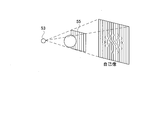
- the radiation source 53 in FIG. 10 emits radiation in phase.
- an image of the phase grating 55 appears on a projection plane separated from the phase grating 55 by a predetermined distance (Talbot distance).
- This image is called a self-image.
- the self image is not simply a projection image of the phase grating 55.
- the self-image occurs only at a position where the projection plane is separated from the phase grating 55 by the Talbot distance.
- the self-image is composed of interference fringes generated by light interference.
- the reason why the self-image of the phase grating 55 appears at the Talbot distance is that the phases of the radiation generated from the radiation source 53 are aligned. When the phase of radiation is disturbed, the self-image that appears in the Talbot distance is also disturbed.
- the radiation phase contrast imaging device uses the disturbance of the self-image to image the internal structure of the object. Assume that an object is placed between the radiation source and the phase grating 55. Since this object hardly absorbs radiation, most of the radiation incident on the object is emitted to the phase grating 55 side.
- phase of the radiation changes while passing through the object.
- the radiation emitted from the object passes through the phase grating 55 with its phase changed.
- this radiation is observed on the projection plane placed at the Talbot distance, the self-image of the phase grating 55 is disturbed. This degree of disturbance of the self-image represents a change in the phase of the radiation.
- phase change The extent to which the phase of the radiation that has passed through the object is specifically changed depends on where the radiation has passed through the object. If the object has a homogeneous configuration, the change in the phase of the radiation is the same everywhere in the object. However, in general, an object has some internal structure. If radiation is transmitted through such an object, the phase change will not be the same.
- phase change is known, the internal structure of the object can be known.
- the change in phase can be known by observing the self-image of the phase grating 55 at the Talbot distance.
- the self-image of the phase grating 55 is detected by a radiation detector arranged on the phase grating 55 at a predetermined distance.
- the separation distance between the phase grating 55 and the radiation detector is not limited. If the separation distance is not appropriate, the self-image will not be reflected on the radiation detector.
- the appropriate separation distance is determined by the distance from the radiation source 53 to the phase grating 55, the fineness of the pattern that forms the phase grating 55, and the wavelength of the radiation output from the radiation source 53.
- Patent Document 1 introduces a mathematical formula that associates these parameters. If an appropriate separation distance is to be obtained, other parameters such as the distance from the radiation source 53 to the phase grating 55 may be substituted into the formula.
- the above-described conventional technology has the following problems. That is, the apparatus of the conventional configuration is not configured in accordance with the actual situation of the radiation source.
- such a radiation source 53 is used and how to make the separation distance between the phase grating 55 and the radiation detector appropriate. If the distance from the radiation source 53 to the phase grating 55 and the fineness of the blurred pattern constituting the phase grating 55 are constant, an appropriate separation distance is determined by the wavelength of the radiation. If the wavelength of the radiation emitted from the radiation source 53 is constant, an appropriate separation distance can be easily determined based on the wavelength. However, if the radiation source 53 that radiates various wavelengths is used, it becomes difficult to know what wavelength can be substituted for the mathematical formula for obtaining an appropriate separation distance.
- the present invention has been made in view of such circumstances, and an object thereof is to provide a radiation phase difference imaging apparatus in which a separation distance between a phase grating and a radiation detector is optimized. is there.
- the radiation phase contrast imaging apparatus is a phase in which a radiation source that irradiates a plurality of types of radiation having different wavelengths and an absorber that absorbs radiation in one direction are arranged in a direction orthogonal to one direction.
- a grating a detection unit for detecting a self-image of a phase grating caused by Talbot interference on a detection surface for detecting radiation, and a self-image generation unit for generating a self-image image in which the self-image is captured based on an output of the detection unit;
- a perspective image generation unit that generates a perspective image in which the phase difference in the subject is imaged based on the self-image, and the distance between the phase grating and the detection surface of the detection unit is determined by the self-image reflected on the detection surface. It is determined based on whether it is disturbed by noise to some extent.
- the separation distance between the phase grating and the radiation detector can be obtained as the Talbot distance.
- the Talbot distance can be uniquely determined only when the radiation source emits a single wavelength.
- the separation distance between the phase grating and the detection surface of the detection unit is determined based on how much the self-image reflected on the detection surface is disturbed by noise. That is, in the configuration of the present invention, the magnitude of the influence of noise is set as a reference for evaluating the separation distance.
- the distance Zd is appropriate for photographing depending on how much the self-image on the self-image obtained when the distance between the phase grating and the detection surface of the detection unit is a certain distance Zd is disturbed by noise. Judge. If it is determined that the noise disturbance is sufficiently small and the distance Zd is appropriate for photographing, it is possible to set the distance Zd as the distance between the phase grating and the detection surface of the detection unit, and the noise disturbance is too large. If the distance Zd is determined to be inappropriate for shooting, the appropriateness for shooting can be found by repeating the determination of appropriateness while changing the separation distance. In this way, the separation distance can be optimized based on the actual situation of the actual radiation source that emits a plurality of types of radiation.
- the distance between the phase grating and the detection unit is a standard that guarantees the visibility of the fluoroscopic image by the noise influence degree indicating how much the noise component appears in the self-image. It is more desirable if it is determined by satisfying.
- the contrast of the self-image captured in the self-image image and the intensity of the noise component captured in the self-image image when the phase grating and the detection surface are separated by a certain distance Zd are shown. It is more desirable if the distance between the phase grating and the detection surface is determined based on the noise influence degree calculated based on the noise intensity.
- the above-described configuration more specifically shows the apparatus of the present invention.
- the contrast and noise intensity of the self image when the phase grating and the detection surface are separated from each other by a certain distance Zd are calculated, and the distance Zd is allowed to shoot the self image based on the noise influence calculated from these. If the setting is evaluated, the suitability of the distance between the phase grating and the detection surface of the detection unit can be more reliably evaluated.
- the noise influence degree is calculated by dividing the contrast by the noise intensity, and the distance when the noise influence degree is equal to or less than a predetermined upper limit value. It is more desirable if Zd is evaluated as a setting that is acceptable for photographing a self-image and the distance Zd is evaluated as a setting that is not permitted for photographing a self-image when it is greater than a predetermined upper limit.
- the noise influence degree is calculated by dividing the contrast by the noise intensity, the noise influence degree is surely calculated. Further, when the noise influence level is equal to or less than a predetermined upper limit value, it is evaluated that the distance Zd is a setting that is allowed for photographing a self image, and when the noise influence degree is larger than the predetermined upper limit value, the distance Zd is allowed for photographing the self image. If it is evaluated that the setting is not performed, it is possible to reliably suppress the distance between the phase grating and the detection surface from being set so that the influence of noise is strongly exerted on the self-image.
- the above-described configuration more specifically shows the apparatus of the present invention.
- the intensity calculation unit can more reliably calculate the noise influence degree by calculating the contrast and noise intensity based on the actually measured self-image or simulation.
- the separation distance between the phase grating and the detection surface of the detection unit is determined based on how much the self-image reflected on the detection surface is disturbed by noise. That is, in the configuration of the present invention, the magnitude of the influence of noise is set as a reference for evaluating the separation distance. According to the present invention, the distance Zd is appropriate for photographing depending on how much the self-image on the self-image obtained when the distance between the phase grating and the detection surface of the detection unit is a certain distance Zd is disturbed by noise. Judge. In this way, the separation distance can be optimized based on the actual situation of the actual radiation source that emits a plurality of types of radiation.
- FIG. 1 is a functional block diagram illustrating an overall configuration of a radiation phase difference imaging apparatus according to Embodiment 1.
- FIG. FIG. 3 is a plan view illustrating configurations of an FPD and a phase grating according to the first embodiment. It is a functional block diagram explaining the structure of the distance judgment part which concerns on Example 1.
- FIG. It is a schematic diagram explaining the determination method whether the distance between the phase grating
- X-rays in the examples correspond to the radiation of the present invention.
- FPD in an Example is the abbreviation for a flat panel detector.
- the radiation phase contrast imaging apparatus of the present invention can take an image of the subject M with little radiation absorption, and thus is suitable for fluoroscopy of a substrate for industrial use and for fluoroscopy of a breast for medical use. It is assumed that the distance between the X-ray source 3 and the phase grating 5 and the arrangement pitch of the absorption lines 5a arranged on the phase grating 5 are constant. On the other hand, the distance between the phase grating 5 and the FPD 4 can be adjusted by moving the FPD 4 with respect to the phase grating 5.
- FIG. 1 shows the overall configuration of a photographing apparatus 1 according to the present invention.
- the imaging apparatus 1 includes a mounting table 2 on which a subject M is mounted, an X-ray source 3 that is provided above the mounting table 2 and that irradiates an X-ray beam that spreads in a pyramid shape, and an X-ray source 3, and an FPD 4 that detects X-rays transmitted through the subject M on the mounting table 2.
- a phase grating 5 that causes Talbot interference is provided at a position between the FPD 4 and the mounting table 2.
- the FPD 4 is configured to detect a self-image of the phase grating 5 caused by Talbot interference on the detection surface 4a for detecting X-rays.
- the X-ray source 3 corresponds to the radiation source of the present invention
- the FPD 4 corresponds to the detection unit of the present invention.
- the X-ray source 3 emits a plurality of types of X-rays having different wavelengths. That is, the X-rays output from the X-ray source 3 include those having the relatively long wavelength and those having the relatively short wavelength even if the X-ray is the same. Accordingly, the X-ray source 3 does not emit monochromatic X-rays.
- the shape of the wavelength spectrum of X-rays output from the X-ray source 3 is constant.
- the imaging apparatus 1 is a radiation imaging apparatus using Talbot interference. Therefore, the X-ray source 3 is configured to output an X-ray beam having the same phase. A self-image of the phase grating 5 appears on the detection surface for detecting the X-rays of the FPD 4. Normally, the distance between the phase grating 5 and the FPD 4 is set to the Talbot distance, but the present invention is characterized in that the distance is determined from another point of view without being bound by such custom. . In the configuration of the present invention, it is difficult to set the distance between the phase grating 5 and the FPD 4 strictly to the Talbot distance. This is because the X-ray source 3 emits X-rays having a plurality of different wavelengths.
- the self-image image generation unit 11 generates a self-image of the phase grating 5 based on the output of the FPD 4.
- the generated self-image is output to the fluoroscopic image generator 12.
- the perspective image generation unit 12 generates a perspective image Pa in which the phase difference of the X-rays generated in the subject M is imaged based on the self-image of the phase grating 5.
- the X-ray source control unit 6 is provided for the purpose of controlling the X-ray source 3. During imaging, the X-ray source control unit 6 controls the X-ray source 3 so as to output an X-ray beam in a pulse shape. When the X-ray source 3 outputs an X-ray beam, the FPD 4 detects X-rays transmitted through the subject M and the phase grating 5 on the mounting table 2 and sends detection data to the self-image image generation unit 11. As described above, the apparatus of the present invention is configured to generate a self-image by taking an X-ray image.
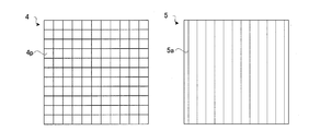
- the left side of FIG. 2 describes the detection surface 4a of the FPD 4.
- detection elements 4 p having a rectangular shape of 20 ⁇ m long ⁇ 20 ⁇ m wide are arranged vertically and horizontally. The sizes of the detection element 4p and the detection surface 4a can be appropriately changed.
- the FPD4 is a direct conversion type X-ray detector. That is, the FPD 4 has a conversion layer that converts X-rays into electron and hole pairs (carrier pairs). Carriers generated in the conversion layer are captured and accumulated in each of the detection elements 4p. When a signal for outputting a carrier is sent to the detection element 4p, the detection element 4p outputs the accumulated carrier as a detection signal.
- the fineness of the detection element 4p is the main factor that determines the spatial resolution of the FPD 4. As the detection element 4p is smaller, the spatial resolution of the FPD 4 is improved, and a finer structure can be detected.
- the right side of FIG. 2 describes the phase grating 5.
- the phase grating 5 is shaped so that the projection of the X-ray beam is reflected in the entire detection surface 4a of the FPD 4. Therefore, the phase grating 5 has a rectangular structure like the detection surface 4a of the FPD 4.
- the phase grating 5 has a plurality of absorption lines 5a extending linearly to absorb X-rays.
- the absorption lines 5a are arranged at a predetermined pitch in a direction orthogonal to the extending direction.
- the direction in which the absorption line 5a of the phase grating 5 extends coincides with the longitudinal direction in which the detection elements 4p are arranged on the detection surface 4a of the FPD 4, and the direction in which the absorption line 5a of the phase grating 5 is arranged is FPD4. This coincides with the horizontal direction of the detection surface 4a.
- absorbers extending in one direction that absorb X-rays are arranged in a direction orthogonal to one direction.
- the FPD 4 sends an X-ray detection signal to the self-image image generation unit 11.
- the self-image image generation unit 11 generates a self-image image P1 in which the self-image is reflected based on the transmitted detection signal.
- This self-image P1 is an image in which the phase grating 5 is reflected as a whole.
- the self-image image P ⁇ b> 1 captured with the subject M set includes the absorption line 5 a of the phase grating 5 being distorted in some places. This distortion represents the internal structure of the subject M due to unevenness in the phase difference of the X-rays while the X-rays pass through the subject M.
- the self-image image P1 is sent to the fluoroscopic image generation unit 12.
- the perspective image generation unit 12 generates a perspective image Pa in which the phase difference in the subject is imaged based on the self-image image P1 generated by the self-image image generation unit 11.
- the distance determination unit 15 is configured to determine the distance between the phase grating 5 and the FPD 4.
- the distance here is the distance from the phase grating 5 to the detection surface 4a of the FPD 4.
- the distance determination unit 15 is mounted on the photographing apparatus 1, but the present invention is not limited to this configuration.
- the distance determination unit 15 may be an apparatus independent of the imaging apparatus 1, and the positional relationship between the phase grating 5 and the FPD 4 in the imaging apparatus 1 may be adjusted based on the output of the apparatus.
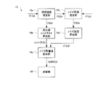
- FIG. 3 illustrates the configuration of the distance determination unit 15 that determines the distance between the phase grating 5 and the FPD 4. As shown in FIG. 3, the distance determination unit 15 estimates the ideal image P2Zd based on the actually measured self-image P1Zd, calculates the contrast of the self-image based on the ideal image P2Zd, and based on the ideal image P2Zd.
- a noise component included in the self-image image P1Zd is estimated to generate a noise image P3Zd, the intensity of noise in the self-image image P1Zd is calculated based on the noise image P3Zd, and the contrast I (Zd) max ⁇ I (Zd) min
- the noise influence degree indicating how much the self-image on the self-image is disturbed by noise is calculated based on the noise intensity ⁇ (Zd)
- the self-image image P1Zd is photographed based on the noise influence degree It is configured to evaluate whether the distance between the phase grating 5 and the FPD 4 is appropriate for taking a self-image.
- the ideal image estimation unit 15a corresponds to the intensity calculation unit of the present invention
- the noise intensity calculation unit 15d corresponds to the intensity calculation unit of the present invention.
- the distance between the phase grating 5 and the FPD 4 is considered to have an optimum distance based on the principle of Talbot interference.
- the optimum distance in the actual apparatus cannot always be calculated by calculation based on the Talbot interference principle. This is because in the calculation based on the principle of Talbot interference, the X-ray source 3 calculates the distance on the assumption that only a single wavelength of X-rays is irradiated. Since the X-ray source 3 in the present invention is configured to irradiate a plurality of X-rays having different wavelengths, there is no guarantee that an appropriate distance for imaging can be calculated even if this is ignored.
- the configuration of the present invention focuses on noise that appears in the self-image.
- the influence of noise reflected in the self-image image changes.
- the influence of noise increases or decreases.
- the degree of influence of noise reflected in the self-image for a certain distance is calculated, and based on the result, it is verified whether the distance is suitable for photographing the self-image. ing.
- the distance between the phase grating 5 and the detection surface 4a of the FPD 4 is determined based on how much the self image reflected on the detection surface 4a is disturbed by noise.
- a value called a noise influence degree is considered as a value indicating the degree of the influence of noise.
- the noise influence level changes accordingly. Therefore, the noise influence level is a variable of distance.
- the distance between the phase grating 5 and the FPD 4 is determined based on whether or not the noise influence degree indicating how much the influence of the noise component appears in the self-image image P1 satisfies the criterion for guaranteeing the visibility of the fluoroscopic image Pa.
- ⁇ Calculation method of CNR> a procedure for calculating the noise influence level when the distance between the phase grating 5 constituting the imaging apparatus 1 and the detection surface 4a of the FPD 4 is Zd will be described as an example of the noise influence level calculation method. If the noise influence calculated at this time is sufficiently low, it can be said that the distance Zd is suitable for photographing.
- a self-image is taken with the photographing apparatus 1 in which the detection surface 4a of the FPD 4 is actually separated from the phase grating 5 by the distance Zd.
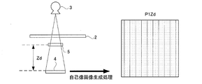
- FIG. 4 shows how the self-image image P1Zd relating to the distance Zd is generated by this shooting.
- This self-image P1Zd is taken in a state where nothing is placed on the mounting table 2.
- the self-image image P1Zd may be taken with the mounting table 2 removed from the photographing apparatus 1.
- the captured self-image P1Zd is an image in which self-images indicated by vertical stripes in FIG. 4 and noise indicated by shading are simultaneously reflected. It should be noted that the self-image image P1Zd is distinguished from the above-described self-image image P1 in which the subject M is reflected.
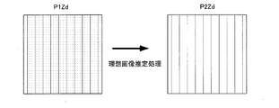
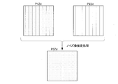
- the generated self-image image P1Zd is sent to the ideal image estimation unit 15a of the distance determination unit 15. As shown in FIG. 5, the ideal image estimation unit 15a estimates a self image reflected in the self image P1Zd and generates an ideal image P2Zd.
- the ideal image P2Zd represents a self-image that should be obtained when no noise is captured at the time of shooting the self-image P1.
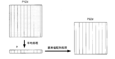
- FIG. 6 shows the operation of the ideal image estimation unit 15a more specifically.
- the ideal image estimation unit 15a pays attention to the column of pixels lined up in the vertical direction in the self-image image P1Zd, acquires the average value of the pixel values for each column, and sets the average value corresponding to each pixel column to the arrangement of each pixel column
- the average value profile p is generated by sequentially arranging in the horizontal direction. That is, the ideal image estimation unit 15a performs the pixel value averaging process in a direction (vertical direction in FIG. 6) in which the self-image stripe pattern in the self-image image P1Zd extends. The noise components superimposed on the self-image are canceled out by the averaging process and do not appear on the average value profile p.
- the self-image composed of dark lines extending in the vertical direction pixel values are only averaged between pixels constituting the dark lines by the averaging process. Therefore, a self-image appears on the average value profile p.
- the ideal image estimation unit 15a generates the ideal image P2Zd by arranging the average value profiles p in the vertical direction.
- the ideal image P2Zd generated in this way has the same number of pixels arranged vertically and horizontally as the self-image image P1Zd.
- the ideal image P2Zd thus generated is an image as if a striped self-image was extracted from the self-image P1Zd.
- the ideal image P2Zd is sent to the self-image contrast calculation unit 15b.
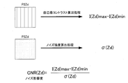
- the self-image contrast calculation unit 15b samples the pixel value I (Zd) max of the pixels constituting the bright line of the ideal image P2Zd and the pixel value I (Zd) min of the pixels constituting the dark line, and the difference between these values is sampled. A certain contrast is calculated.
- the contrast can be expressed as I (Zd) max-I (Zd) min.
- a method of determining the pixel value I (Zd) max a method of selecting the pixel value of the brightest pixel from the ideal image P2Zd can be considered.
- the self-image contrast calculation unit 15b does not necessarily calculate the contrast based on the ideal image P2Zd.
- the ideal image estimation unit 15a can also calculate contrast based on the average value profile p generated during image processing.
- the self-image contrast calculation unit 15b calculates the contrast of the self-image captured in the captured self-image image P1Zd when the phase grating 5 and the detection surface 4a are separated by a certain distance Zd.
- the self-image contrast calculation unit 15b calculates the contrast based on the actually measured self-image image P1Zd.
- the ideal image P2Zd is also sent to the noise image estimation unit 15c.
- the noise image estimation unit 15c subtracts the ideal image P2Zd from the self-image image P1Zd to generate a noise image P3Zd in which only noise components on the self-image image P1Zd are reflected.
- This noise image P3Zd is an image as if a sandstorm-like noise component was extracted from the self-image image P1Zd.
- the noise image P3Zd is sent to the noise intensity calculation unit 15d.
- the noise intensity calculation unit 15d calculates the noise intensity ⁇ (Zd) reflected in the noise image P3Zd by statistically evaluating the pixel values of the pixels constituting the noise image P3Zd.
- the noise intensity ⁇ (Zd) may be a variance of pixel values.
- the noise intensity calculation unit 15d has a noise intensity ⁇ () indicating the intensity of the noise component output by the FPD 4 when the self-image image P1 is generated when the phase grating 5 and the detection surface 4a are separated by a certain distance Zd. Zd) is calculated.
- the noise intensity calculator 15d calculates the noise intensity ⁇ (Zd) based on the actually measured self-image image P1.
- the contrast and the noise intensity ⁇ (Zd) are sent to the noise influence calculation unit 15e.
- the noise influence degree calculation unit 15e calculates the noise influence degree (CNR (Zd)) by dividing the noise intensity (Zd) from the contrast.
- This noise influence degree is a concept similar to the S / N ratio, and is an index indicating how much the self-image on the self-image P1Zd is disturbed by noise.
- FIG. 8 conceptually shows the operations of the self-image contrast calculation unit 15b, the noise intensity calculation unit 15d, and the noise influence calculation unit 15e. In this way, the noise influence degree calculation unit 15e calculates the noise influence degree (CNR (Zd))) based on the contrast and the noise intensity ⁇ (Zd).
- the noise influence degree is sent to the evaluation unit 15f.
- the evaluation unit 15f determines the distance Zd from the phase grating 5 to the detection surface of the FPD 4 for the purpose of photographing a self image. Evaluation that it is allowed as a distance up to 4a is performed.
- the evaluation unit 15f evaluates that the distance Zd is not allowed as the distance from the phase grating 5 to the detection surface 4a of the FPD 4 for the purpose of photographing a self image. .
- the operator can know whether the distance Zd is appropriate for photographing by the evaluation output by the evaluation unit 15f.
- the detection surface 4a of the FPD 4 should not be separated from the phase grating 5 by a distance estimated to be inappropriate. Otherwise, a clear self-portrait cannot be taken. In this way, the evaluation unit 15f evaluates whether or not the distance Zd is a setting permitted for photographing a self image based on the noise influence degree.
- the upper limit value stored in the storage unit 27 indicates the limit of the noise influence level allowed when taking a self-image. If the noise influence level is larger than the upper limit value, it can be determined that the noise reflected in the self-image image P1Zd is too intense to capture the self-image.
- the upper limit value is determined based on the visibility of the fluoroscopic image Pa generated based on the self-image rather than being determined based on the visibility of the self-image.
- the perspective image Pa is obtained by analyzing a self-image having a striped pattern, and represents the internal structure of the subject.
- the photographed self-image is an image in which sandstorm-like noise is superimposed on a striped pattern that is the self-image itself.
- the fluoroscopic image Pa is generated based on such a self-image, the subject image on the fluoroscopic image is disturbed by the influence of noise on the self-image.
- the fluoroscopic image Pa is disturbed due to noise on the self-image, but if the disturbance is too strong, the observation of the subject image on the fluoroscopic image is hindered.
- the upper limit value stored in the storage unit 27 represents the noise influence degree of the self-image image that is based on the fluoroscopic image Pa that is considered to hinder visual recognition when the subject image is more disturbed. Therefore, even if the fluoroscopic image Pa is generated based on the self-image image having a noise influence level larger than the upper limit value, only the fluoroscopic image Pa having a problem in visibility can be obtained.
- a self-portrait image having a noise influence level larger than the upper limit value should not be taken from the beginning. Such a self-image was taken in a state where the distance from the phase grating 5 to the detection surface 4a of the FPD 4 was inappropriate.
- the distance from the phase grating 5 to the detection surface 4a of the FPD 4 is inappropriate.
- the generation of the perspective image Pa that is disturbed so as to hinder visual recognition is prevented.
- a composite image is generated by synthesizing a sandstorm-like noise component with a self-portrait image captured with the subject placed on the mounting table 2, and a perspective generated based on the composite image
- the image Pa can be confirmed and obtained.
- a plurality of synthesized images are generated by changing the strength of the noise component to be synthesized with the self-image, and the perspective image Pa is generated based on these, a perspective image Pa having a noise component that is barely permissible appears.
- the noise influence degree of the composite image on which the fluoroscopic image Pa is based is an upper limit value.
- the noise influence level at this time can be obtained from the contrast calculated from the self-image and the noise intensity calculated from the noise component.
- the noise component of the self-image before synthesis is preferably as small as possible. Therefore, it is better to take a self-image when the upper limit value is determined with a longer exposure time.
- the main control unit 21 shown in FIG. 1 is provided for the purpose of comprehensively controlling the units 6, 11, 12, 14, and 15.
- the main control unit 21 is constituted by a CPU, and realizes each unit by executing various programs. Further, these units 6, 11, 12, 14, 15, 15a, 15b, 15c, 15d, 15e, and 15f may be executed by being divided into arithmetic units in charge of them. Each unit can access the storage unit 27 as necessary.
- the console 25 is provided for the purpose of inputting operator instructions.
- the display unit 26 is provided for the purpose of displaying a fluoroscopic image.
- the separation distance between the phase grating 5 and the X-ray detector is optimized.
- the separation distance between the phase grating 5 and the X-ray detector can be obtained as the Talbot distance.
- the Talbot distance can be uniquely determined only when the X-ray source 3 emits a single wavelength.
- the separation distance between the phase grating 5 and the detection surface 4a of the FPD 4 is determined based on how much the self-image reflected on the detection surface 4a is disturbed by noise. That is, in the configuration of the present invention, the magnitude of the influence of noise is set as a reference for evaluating the separation distance. According to the present invention, the distance Zd is used for shooting depending on how much the self-image on the self-image obtained when the distance between the phase grating 5 and the detection surface 4a of the FPD 4 is a certain distance Zd is disturbed by noise. Determine if appropriate.
- the distance Zd between the phase grating 5 and the detection surface 4a of the FPD 4 can be set to the distance Zd, and when the distance Zd is determined inappropriate for photographing.
- the separation distance can be optimized based on the actual situation of the actual X-ray source 3 that emits a plurality of types of X-rays.
- the present invention is not limited to the embodiments and can be modified as follows.
- the noise influence degree is calculated by actually measuring the self-image image P1, but the present invention is not limited to this configuration.
- the noise influence degree can also be calculated by simulation. A method for obtaining the noise influence level by simulation will be described.
- the X-ray source 3 emits single-wavelength X-rays.
- what kind of self-image is reflected on the detection surface 4a of the FPD 4 separated from the phase grating 5 by a predetermined distance Zd can be easily obtained by simulation.
- the wavelength of the X-ray emitted from the X-ray source 3 is ⁇ a
- the self-image that appears on the detection surface 4a of the FPD 4 at this time is S (Zd) ⁇ a .
- the self-image changes as Zd changes.
- a self-image S (Zd) ⁇ a corresponding to an arbitrary distance Zd can be obtained by simulation.
- a self-image S (Zd) ⁇ 1 corresponding to an arbitrary wavelength ⁇ 1 can also be obtained by simulation.
- a plurality of self-images can be obtained by changing the wavelength ⁇ .
- self-images S (Zd) ⁇ 1 , S (Zd) ⁇ 2 , S (Zd) ⁇ 3 ,... are calculated for wavelengths ⁇ 1, ⁇ 2, ⁇ 3,. This is simply written as S ⁇ 1 , S ⁇ 2 , S ⁇ 3,.
- the actual X-ray source 3 includes a plurality of radiations having different wavelengths ⁇ 1, ⁇ 2, ⁇ 3,. Assuming that a self-image is taken using such an X-ray source 3, the self-image S (Zd) ⁇ 1, ⁇ 2, ⁇ 3 is present on the detection surface 4a of the FPD 4 that is separated from the phase grating 5 by a predetermined distance Zd. , ... appears. This is simply written as S ⁇ 1, ⁇ 2, ⁇ 3,. This self-image can be expressed as follows by the self-images S ⁇ 1 , S ⁇ 2 , S ⁇ 3,. S ⁇ 1, ⁇ 2, ⁇ 3,...
- Self images S (Zd) ⁇ 1, ⁇ 2, ⁇ 3,... can be calculated by simulation.
- Self images S (Zd) ⁇ 1, ⁇ 2, ⁇ 3,... Are images corresponding to the ideal image P2Zd in the first embodiment, and are estimated by the ideal image estimation unit 15a.
- the actual method of obtaining the noise intensity ⁇ (Zd) is the same as the self-image S (Zd) ⁇ 1, ⁇ 2, ⁇ 3,.
- the X-ray source 3 emits single-wavelength X-rays.
- what kind of noise component is reflected on the detection surface 4a of the FPD 4 separated from the phase grating 5 by a predetermined distance Zd can be easily obtained by simulation.
- the wavelength of X-rays emitted from the X-ray source 3 is ⁇ a
- the intensity of noise appearing on the detection surface 4a of the FPD 4 at this time is ⁇ (Zd) ⁇ a .
- the self-image changes as Zd changes.
- the noise intensity ⁇ (Zd) ⁇ a corresponding to an arbitrary distance Zd can be obtained by simulation.
- noise intensity ⁇ (Zd) ⁇ 1 corresponding to an arbitrary wavelength ⁇ 1 can also be obtained by simulation.
- a plurality of self-images can be obtained by changing the wavelength ⁇ .
- Noise intensities ⁇ (Zd) ⁇ 1 , ⁇ (Zd) ⁇ 2 , ⁇ (Zd) ⁇ 3 This is simply written as ⁇ ⁇ 1 , ⁇ ⁇ 2 , ⁇ ⁇ 3,.
- the actual X-ray source 3 includes a plurality of radiations having different wavelengths ⁇ 1, ⁇ 2, ⁇ 3,. If a self-image is taken using such an X-ray source 3, a certain noise intensity ⁇ (Zd) ⁇ 1, ⁇ 2 is present on the detection surface 4 a of the FPD 4 separated from the phase grating 5 by a predetermined distance Zd . ⁇ 3 ... appears. This is simply written as ⁇ ⁇ 1, ⁇ 2, ⁇ 3,. This self-image can be expressed as follows with the noise intensities ⁇ ⁇ 1 , ⁇ ⁇ 2 , ⁇ ⁇ 3,. ⁇ ⁇ 1, ⁇ 2, ⁇ 3, ...
- k1, k2, k3,... are coefficients determined by how much each wavelength ⁇ 1, ⁇ 2, ⁇ 3,... Is output from the actual X-ray source 3. This coefficient can be easily obtained from the wavelength spectrum of X-rays output from the X-ray source 3.
- the noise intensity ⁇ (Zd) ⁇ 1, ⁇ 2, ⁇ 3,... can be calculated by simulation.
- the noise intensity ⁇ (Zd) ⁇ 1, ⁇ 2, ⁇ 3,... Corresponds to the noise intensity (Zd) in the first embodiment, and is estimated by the noise intensity calculator 15d.
- the self-image contrast calculation unit 15b calculates the contrast based on the simulation
- the noise intensity calculation unit 15d calculates the noise intensity based on the simulation.
- an absorption grating 7 may be provided so as to cover the detection surface 4 a of the FPD 4.
- the absorption grating 7 has a configuration in which absorption lines are arranged in the same manner as the phase grating 5, and is provided for the purpose of generating moire by interference with the self-image of the phase grating 5.
- the FPD 4 can estimate the self-image by detecting this moire. That is, an absorption grating 7 that generates moire between the phase grating 5 and the self-image of the phase grating 5 is provided between the phase grating 5 and the FPD 4 of this modification.
- the X-ray source 3 is a single focus, but the present invention is not limited to this configuration.
- the present invention can also be applied to a configuration in which the X-ray source 3 has a plurality of X-ray generation points.
- the present invention is suitable for a medical imaging apparatus.
Landscapes
- Health & Medical Sciences (AREA)
- Life Sciences & Earth Sciences (AREA)
- Engineering & Computer Science (AREA)
- Medical Informatics (AREA)
- Pathology (AREA)
- General Health & Medical Sciences (AREA)
- Physics & Mathematics (AREA)
- Nuclear Medicine, Radiotherapy & Molecular Imaging (AREA)
- Radiology & Medical Imaging (AREA)
- Surgery (AREA)
- Veterinary Medicine (AREA)
- Biomedical Technology (AREA)
- Heart & Thoracic Surgery (AREA)
- Molecular Biology (AREA)
- High Energy & Nuclear Physics (AREA)
- Animal Behavior & Ethology (AREA)
- Biophysics (AREA)
- Public Health (AREA)
- Optics & Photonics (AREA)
- Chemical & Material Sciences (AREA)
- Analytical Chemistry (AREA)
- Biochemistry (AREA)
- General Physics & Mathematics (AREA)
- Immunology (AREA)
- Computer Vision & Pattern Recognition (AREA)
- Multimedia (AREA)
- Crystallography & Structural Chemistry (AREA)
- Apparatus For Radiation Diagnosis (AREA)
- Analysing Materials By The Use Of Radiation (AREA)
Abstract
Description
すなわち、従来構成の装置は、十分に放射線源の実情に即した構成とはなっていない。
すなわち、本発明に係る放射線位相差撮影装置は、波長の異なる複数種類の放射線を照射する放射線源と、放射線を吸収する1方向に伸びる吸収体が1方向と直交する方向に配列されている位相格子と、放射線を検出する検出面でタルボ干渉によって生じる位相格子の自己像を検出する検出部と、検出部の出力に基づいて自己像を写し込んだ自己像画像を生成する自己像生成部と、自己像画像に基づいて被写体内の位相差がイメージングされた透視画像を生成する透視画像生成部を備え、位相格子と検出部の検出面との距離は、検出面に写り込む自己像がどの程度ノイズにより乱されるかを基準に決定されていることを特徴とするものである。
本発明によれば、位相格子と検出部の検出面との離間距離は、検出面に写り込む自己像がどの程度ノイズにより乱されるかを基準に決定される。すなわち、本発明の構成では、ノイズの影響の大きさを離間距離の評価の基準に定めている。そして、本発明によれば位相格子と検出部の検出面との距離をある距離Zdとしたときに得られる自己画像上の自己像がどの程度ノイズに乱されるかで距離Zdが撮影に適切か判断する。ノイズの乱れが十分に小さく距離Zdが撮影に適切と判断された場合は、位相格子と検出部の検出面との離間距離を距離Zdに定めることが可能であるし、ノイズの乱れが大きすぎて距離Zdが撮影に不適切と判断された場合は、離間距離を変えながら適切性の判断を繰り返すことにより、撮影に適切な距離を見つけ出すことができる。このようにすれば、複数種類の放射線を照射する実際の放射線源の実情に基づいて離間距離の最適化ができる。
距離判断部15がどのようにして位相格子とFPD4との間の距離を決定するかについて概念的に説明する。位相格子5とFPD4との距離としては、タルボ干渉の原理に基づいた最適な距離があるものと考えられる。しかし、装置を構成するときのことまで考慮すると、実際の装置における最適な距離がタルボ干渉の原理に基づく計算で算出できるとは限らない。タルボ干渉の原理に基づく計算では、X線源3は単波長のX線のみを照射するという前提で距離を算出するようになっているからである。本発明におけるX線源3は、波長の異なる複数のX線を照射する構成であるので、これを無視して計算をしても、撮影に適切な距離が算出できる保証はない。
以降、ノイズ影響度の算出方法の例として撮影装置1を構成する位相格子5とFPD4の検出面4aとの間の距離がZdであるときのノイズ影響度の算出手順について説明する。このとき算出されるノイズ影響度が十分低い場合、距離Zdは撮影に適していると言える。このノイズ影響度を算出するには、位相格子5からFPD4の検出面4aを実際に距離Zdに離間させた状態となっている撮影装置1で自己像の撮影をする。図4は、この撮影により、距離Zdに係る自己像画像P1Zdが生成される様子を示している。この自己像画像P1Zdは、載置台2に何も置いていない状態で撮影される。また、載置台2を撮影装置1から取り外した状態で自己像画像P1Zdの撮影を行うようにしてもよい。撮影された自己像画像P1Zdには、図4の縦縞で示す自己像と、網掛けで示すノイズとが同時に写り込んだような画像となっている。自己像画像P1Zdは、被写体Mが写り込んだ上述の自己像画像P1とは区別されているので注意が必要である。
Sλ1,λ2,λ3,…=k1・Sλ1+k2・Sλ2+k3・Sλ3+…
ここで、k1,k2,k3,…は、各波長λ1,λ2,λ3,…が実際のX線源3からどの程度出力されるのかによって決まる係数である。この係数は、X線源3から出力されるX線の波長スペクトルによって容易に求めることができる。
σλ1,λ2,λ3,…=k1・σλ1+k2・σλ2+k3・σλ3+…
ここで、k1,k2,k3,…は、各波長λ1,λ2,λ3,…が実際のX線源3からどの程度出力されるのかによって決まる係数である。この係数は、X線源3から出力されるX線の波長スペクトルによって容易に求めることができる。
4 FPD(検出部)
4a 検出面
5 位相格子
7 吸収格子
P1 自己像画像
Pa 透視画像
11 自己像生成部
12 透視画像生成部
15b 自己像コントラスト算出部(強度算出部)
15d ノイズ強度算出部(強度算出部)
15e ノイズ影響度算出部(ノイズ影響度算出部)
Claims (5)
- 波長の異なる複数種類の放射線を照射する放射線源と、
放射線を吸収する1方向に伸びる吸収体が1方向と直交する方向に配列されている位相格子と、
放射線を検出する検出面でタルボ干渉によって生じる前記位相格子の自己像を検出する検出部と、
前記検出部の出力に基づいて自己像を写し込んだ自己像画像を生成する自己像生成部と、
前記自己像画像に基づいて被写体内の位相差がイメージングされた透視画像を生成する透視画像生成部を備え、
前記位相格子と前記検出部の前記検出面との距離は、前記検出面に写り込む自己像がどの程度ノイズにより乱されるかを基準に決定されている、放射線位相差撮影装置。 - 請求項1に記載の放射線位相差撮影装置において、
前記位相格子と前記検出部との距離は、前記自己像画像にどの程度ノイズ成分の影響が現れるかを示すノイズ影響度が前記透視画像の視認性を保証する基準を満たすかで決定される、放射線位相差撮影装置。 - 請求項1に記載の放射線位相差撮影装置において、
前記位相格子と前記検出面とがある距離Zdだけ離れているときの前記自己像画像に写り込む自己像のコントラストおよび前記自己像画像に写り込むノイズ成分の強度を示すノイズの強度とに基づいて算出されるノイズ影響度に基づいて前記位相格子と前記検出面との距離の決定がなされている、放射線位相差撮影装置。 - 請求項3に記載の放射線位相差撮影装置において、
前記ノイズ影響度は、前記コントラストを前記ノイズの強度で除算することによって前記ノイズ影響度が算出されたものであり、
前記ノイズ影響度が所定の上限値以下であるとき前記距離Zdが自己像の撮影に許容される設定であると評価され、所定の上限値より大であるとき前記距離Zdが自己像の撮影に許容されない設定であると評価される、放射線位相差撮影装置。 - 請求項3に記載の放射線位相差撮影装置において、
実測された前記自己像画像またはシミュレーションに基づいて前記コントラストおよび前記ノイズの強度が算出される、放射線位相差撮影装置。
Priority Applications (4)
| Application Number | Priority Date | Filing Date | Title |
|---|---|---|---|
| US15/555,663 US10335109B2 (en) | 2015-03-06 | 2015-03-06 | Radiation phase-contrast imaging device |
| PCT/JP2015/056747 WO2016143015A1 (ja) | 2015-03-06 | 2015-03-06 | 放射線位相差撮影装置 |
| JP2017504337A JP6458859B2 (ja) | 2015-03-06 | 2015-03-06 | 放射線位相差撮影装置 |
| CN201580077485.7A CN107427269B (zh) | 2015-03-06 | 2015-03-06 | 放射线相位差摄影装置 |
Applications Claiming Priority (1)
| Application Number | Priority Date | Filing Date | Title |
|---|---|---|---|
| PCT/JP2015/056747 WO2016143015A1 (ja) | 2015-03-06 | 2015-03-06 | 放射線位相差撮影装置 |
Publications (1)
| Publication Number | Publication Date |
|---|---|
| WO2016143015A1 true WO2016143015A1 (ja) | 2016-09-15 |
Family
ID=56878804
Family Applications (1)
| Application Number | Title | Priority Date | Filing Date |
|---|---|---|---|
| PCT/JP2015/056747 Ceased WO2016143015A1 (ja) | 2015-03-06 | 2015-03-06 | 放射線位相差撮影装置 |
Country Status (4)
| Country | Link |
|---|---|
| US (1) | US10335109B2 (ja) |
| JP (1) | JP6458859B2 (ja) |
| CN (1) | CN107427269B (ja) |
| WO (1) | WO2016143015A1 (ja) |
Families Citing this family (3)
| Publication number | Priority date | Publication date | Assignee | Title |
|---|---|---|---|---|
| WO2019073760A1 (ja) * | 2017-10-11 | 2019-04-18 | 株式会社島津製作所 | X線位相差撮影システムおよび位相コントラスト画像補正方法 |
| JP7468373B2 (ja) * | 2021-01-19 | 2024-04-16 | 株式会社島津製作所 | X線撮影装置 |
| CN116613623A (zh) * | 2023-05-24 | 2023-08-18 | 中科融合感知智能研究院(苏州工业园区)有限公司 | 一种激光发生系统、三维成像模组、成像方法及介质 |
Citations (4)
| Publication number | Priority date | Publication date | Assignee | Title |
|---|---|---|---|---|
| JP2010158257A (ja) * | 2007-04-10 | 2010-07-22 | Konica Minolta Medical & Graphic Inc | 放射線画像撮影装置および放射線画像撮影システム |
| JP2010256059A (ja) * | 2009-04-22 | 2010-11-11 | Canon Inc | トールボット干渉計、トールボット干渉計の調整方法、及び露光装置 |
| WO2012057023A1 (ja) * | 2010-10-28 | 2012-05-03 | 富士フイルム株式会社 | 放射線画像撮影システム及びその制御方法 |
| JP2012108098A (ja) * | 2010-10-20 | 2012-06-07 | Canon Inc | トールボット干渉を用いた撮像装置および撮像装置の調整方法 |
Family Cites Families (9)
| Publication number | Priority date | Publication date | Assignee | Title |
|---|---|---|---|---|
| US7809110B2 (en) * | 2005-01-11 | 2010-10-05 | Hitachi Medical Corporation | X-ray imaging device |
| CN101576515B (zh) * | 2007-11-23 | 2012-07-04 | 同方威视技术股份有限公司 | X射线光栅相衬成像系统及方法 |
| CN102802529B (zh) * | 2009-06-16 | 2015-09-16 | 皇家飞利浦电子股份有限公司 | 用于微分相衬成像的校正方法 |
| JP2011206162A (ja) * | 2010-03-29 | 2011-10-20 | Fujifilm Corp | 放射線撮影システム及び方法 |
| JP5601909B2 (ja) | 2010-07-06 | 2014-10-08 | 国立大学法人 東京大学 | X線撮像装置及びこれを用いるx線撮像方法 |
| JP2012030039A (ja) * | 2010-07-09 | 2012-02-16 | Fujifilm Corp | 放射線撮影システム及びその画像処理方法 |
| JP5150711B2 (ja) * | 2010-12-07 | 2013-02-27 | 富士フイルム株式会社 | 放射線撮影装置及び放射線撮影システム |
| US8821015B2 (en) * | 2011-03-08 | 2014-09-02 | Carestream Health, Inc. | Alignment apparatus for X-ray imaging system |
| JP2013208189A (ja) * | 2012-03-30 | 2013-10-10 | Canon Inc | X線撮像装置およびx線撮像方法 |
-
2015
- 2015-03-06 CN CN201580077485.7A patent/CN107427269B/zh not_active Expired - Fee Related
- 2015-03-06 JP JP2017504337A patent/JP6458859B2/ja active Active
- 2015-03-06 WO PCT/JP2015/056747 patent/WO2016143015A1/ja not_active Ceased
- 2015-03-06 US US15/555,663 patent/US10335109B2/en not_active Expired - Fee Related
Patent Citations (4)
| Publication number | Priority date | Publication date | Assignee | Title |
|---|---|---|---|---|
| JP2010158257A (ja) * | 2007-04-10 | 2010-07-22 | Konica Minolta Medical & Graphic Inc | 放射線画像撮影装置および放射線画像撮影システム |
| JP2010256059A (ja) * | 2009-04-22 | 2010-11-11 | Canon Inc | トールボット干渉計、トールボット干渉計の調整方法、及び露光装置 |
| JP2012108098A (ja) * | 2010-10-20 | 2012-06-07 | Canon Inc | トールボット干渉を用いた撮像装置および撮像装置の調整方法 |
| WO2012057023A1 (ja) * | 2010-10-28 | 2012-05-03 | 富士フイルム株式会社 | 放射線画像撮影システム及びその制御方法 |
Also Published As
| Publication number | Publication date |
|---|---|
| US10335109B2 (en) | 2019-07-02 |
| JP6458859B2 (ja) | 2019-01-30 |
| US20180042571A1 (en) | 2018-02-15 |
| CN107427269B (zh) | 2020-10-02 |
| CN107427269A (zh) | 2017-12-01 |
| JPWO2016143015A1 (ja) | 2017-09-28 |
Similar Documents
| Publication | Publication Date | Title |
|---|---|---|
| JP6187298B2 (ja) | X線撮影システム及び画像処理方法 | |
| JP6567094B2 (ja) | 放射線映像の処理方法及び放射線撮影システム | |
| US20180028139A1 (en) | Radiography system, image processing method, and image processing program | |
| JP5835333B2 (ja) | 画像処理装置およびそれを備えた放射線撮影装置 | |
| JP5848697B2 (ja) | X線画像診断装置 | |
| JP2016501630A5 (ja) | ||
| JP2017526457A (ja) | コンピュータ断層撮影法におけるスペクトル及び強度の格子変調のためのシステム及び方法 | |
| JP2011245117A (ja) | X線画像診断装置 | |
| JP2009285356A (ja) | 医療用撮影システム、画像処理装置、画像処理方法、およびプログラム | |
| US20180344268A1 (en) | Apparatus for x-ray imaging an object | |
| JP6458859B2 (ja) | 放射線位相差撮影装置 | |
| JP2019519273A (ja) | 暗視野又は位相コントラストx線撮像における特徴抑制 | |
| JP6750310B2 (ja) | タルボ撮影装置 | |
| JP5526775B2 (ja) | 放射線撮像装置 | |
| CN101874741B (zh) | 放射线摄影装置 | |
| JP6685762B2 (ja) | 画像処理装置、画像処理方法、およびプログラム | |
| JP2013027608A (ja) | 骨梁解析装置 | |
| WO2011058612A1 (ja) | 放射線撮影装置 | |
| JP5753502B2 (ja) | 画像処理装置および方法 | |
| JP6743975B2 (ja) | 断層像生成方法および放射線撮影装置 | |
| JP5152909B2 (ja) | 放射線画像検出装置 | |
| WO2020152989A1 (ja) | 放射線撮影システム、制御装置および制御方法 | |
| JP6365746B2 (ja) | 画像処理装置、x線撮影システム及び画像処理方法 | |
| CN109328035B (zh) | 放射线摄影装置 | |
| JP5753503B2 (ja) | 画像処理装置および方法 |
Legal Events
| Date | Code | Title | Description |
|---|---|---|---|
| 121 | Ep: the epo has been informed by wipo that ep was designated in this application |
Ref document number: 15884512 Country of ref document: EP Kind code of ref document: A1 |
|
| ENP | Entry into the national phase |
Ref document number: 2017504337 Country of ref document: JP Kind code of ref document: A |
|
| WWE | Wipo information: entry into national phase |
Ref document number: 15555663 Country of ref document: US |
|
| NENP | Non-entry into the national phase |
Ref country code: DE |
|
| 122 | Ep: pct application non-entry in european phase |
Ref document number: 15884512 Country of ref document: EP Kind code of ref document: A1 |