WO2016140291A1 - Clavier - Google Patents
Clavier Download PDFInfo
- Publication number
- WO2016140291A1 WO2016140291A1 PCT/JP2016/056516 JP2016056516W WO2016140291A1 WO 2016140291 A1 WO2016140291 A1 WO 2016140291A1 JP 2016056516 W JP2016056516 W JP 2016056516W WO 2016140291 A1 WO2016140291 A1 WO 2016140291A1
- Authority
- WO
- WIPO (PCT)
- Prior art keywords
- light
- incident
- key button
- light source
- axis
- Prior art date
Links
Images


Classifications
-
- H—ELECTRICITY
- H01—ELECTRIC ELEMENTS
- H01H—ELECTRIC SWITCHES; RELAYS; SELECTORS; EMERGENCY PROTECTIVE DEVICES
- H01H13/00—Switches having rectilinearly-movable operating part or parts adapted for pushing or pulling in one direction only, e.g. push-button switch
- H01H13/70—Switches having rectilinearly-movable operating part or parts adapted for pushing or pulling in one direction only, e.g. push-button switch having a plurality of operating members associated with different sets of contacts, e.g. keyboard
- H01H13/83—Switches having rectilinearly-movable operating part or parts adapted for pushing or pulling in one direction only, e.g. push-button switch having a plurality of operating members associated with different sets of contacts, e.g. keyboard characterised by legends, e.g. Braille, liquid crystal displays, light emitting or optical elements
-
- H—ELECTRICITY
- H01—ELECTRIC ELEMENTS
- H01H—ELECTRIC SWITCHES; RELAYS; SELECTORS; EMERGENCY PROTECTIVE DEVICES
- H01H13/00—Switches having rectilinearly-movable operating part or parts adapted for pushing or pulling in one direction only, e.g. push-button switch
- H01H13/02—Details
-
- H—ELECTRICITY
- H01—ELECTRIC ELEMENTS
- H01H—ELECTRIC SWITCHES; RELAYS; SELECTORS; EMERGENCY PROTECTIVE DEVICES
- H01H13/00—Switches having rectilinearly-movable operating part or parts adapted for pushing or pulling in one direction only, e.g. push-button switch
- H01H13/02—Details
- H01H13/023—Light-emitting indicators
-
- H—ELECTRICITY
- H01—ELECTRIC ELEMENTS
- H01H—ELECTRIC SWITCHES; RELAYS; SELECTORS; EMERGENCY PROTECTIVE DEVICES
- H01H13/00—Switches having rectilinearly-movable operating part or parts adapted for pushing or pulling in one direction only, e.g. push-button switch
- H01H13/70—Switches having rectilinearly-movable operating part or parts adapted for pushing or pulling in one direction only, e.g. push-button switch having a plurality of operating members associated with different sets of contacts, e.g. keyboard
-
- G—PHYSICS
- G02—OPTICS
- G02B—OPTICAL ELEMENTS, SYSTEMS OR APPARATUS
- G02B6/00—Light guides; Structural details of arrangements comprising light guides and other optical elements, e.g. couplings
- G02B6/0001—Light guides; Structural details of arrangements comprising light guides and other optical elements, e.g. couplings specially adapted for lighting devices or systems
- G02B6/0011—Light guides; Structural details of arrangements comprising light guides and other optical elements, e.g. couplings specially adapted for lighting devices or systems the light guides being planar or of plate-like form
- G02B6/0013—Means for improving the coupling-in of light from the light source into the light guide
- G02B6/0015—Means for improving the coupling-in of light from the light source into the light guide provided on the surface of the light guide or in the bulk of it
- G02B6/0016—Grooves, prisms, gratings, scattering particles or rough surfaces
-
- H—ELECTRICITY
- H01—ELECTRIC ELEMENTS
- H01H—ELECTRIC SWITCHES; RELAYS; SELECTORS; EMERGENCY PROTECTIVE DEVICES
- H01H9/00—Details of switching devices, not covered by groups H01H1/00 - H01H7/00
- H01H9/18—Distinguishing marks on switches, e.g. for indicating switch location in the dark; Adaptation of switches to receive distinguishing marks
- H01H9/182—Illumination of the symbols or distinguishing marks
Definitions
- the present invention relates to a keyboard.
- Patent Document 1 discloses that light from a light source provided on a substrate is guided to a key top by a prism (light guide) provided inside the key button to illuminate the key top.
- Patent Document 1 the light incident from the incident end of the prism travels while reflecting inside the prism, and then exits from the exit end of the prism toward the key top to illuminate the key top. It is like that. However, since the prism cannot totally reflect the incident light, the incident light may leak from a place other than the exit end. For this reason, the amount of light for illuminating the key top is insufficient and the visibility may be insufficient, and it is required to further improve the visibility of the key buttons.
- the present invention includes a housing that supports a key button so that the key button can reciprocate in an operation direction of the key button, and a board on which an operation detection unit for the key button is provided, and the key button supported by the housing.
- a light source is provided outside the operation detection unit on the substrate, and a light guide that guides light from the light source to the key top of the key button is refracted from air.
- An incident portion that is formed of a material having a high rate and is provided in the housing, and the light guide is disposed opposite to the light source in the axial direction of the axis, An emission part disposed opposite to the key top at a position hidden by the key button as seen from the axial direction of the axis; A guiding portion that guides the light from the light source incident from the incident portion to the emission portion while reflecting the light, and a surface of the incident portion that faces the light source protrudes toward the light source. It was set as the keyboard characterized by having formed in.
- the refractive index of the light guide is larger than the refractive index of air
- the light irradiated from the light source and reaching the incident part is refracted without being reflected by the surface of the incident part, and the incident part From the inside of the light guide.
- Increasing the surface area of the incident part by forming the incident part facing the light source in a curved surface and increasing the surface area of the incident part results in an increase in the amount of light from the light source incident from the incident part. It is possible to secure the amount of light emitted toward the. Therefore, since it is possible to prevent the visibility from being insufficient due to insufficient light amount for illuminating the key top, it is possible to provide a keyboard with excellent visibility that can be used even in a dark place.
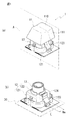
- FIG. 1 is a diagram for explaining a key 1 constituting a keyboard
- (a) is a perspective view of the key 1
- (b) is a state in which a key button 11 is removed from the key 1 shown in (a).
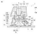
- FIG. 2 is a perspective view showing the plunger 13 supported by the housing 12 and the support portion 122 of the housing.
- FIG. 2 is a diagram illustrating a specific configuration of the key 1, and is a cross-sectional view of the key 1 cut along a plane A in FIG.
- the key button 11 side in FIG. 2 is described as the upper side
- the substrate 30 side is described as the lower side.
- the key 1 includes a key button 11 and a housing 12.
- the key button 11 is moved downward on the housing 12 side by a pressing operation of the key top 110 having a concave upper surface, and the key button 11 in the housing 12 is operated in the operation direction of the key button 11 (FIG. 2). In the vertical direction).
- the key button 11 has a key top 110, a peripheral wall portion 111 that surrounds the outer periphery of the key top 110 over the entire circumference, and a columnar shape that extends downward from the lower surface of the key top 110 to the substrate 30 side.
- the shaft portion 112 is provided.
- the shaft portion 112 is provided substantially at the center of the key top 110, and below the key top 110, a support portion 122 of the housing 12 described later is provided between the outer periphery of the shaft portion 112 and the inner periphery of the peripheral wall portion 111.
- An enterable space 114 is formed.
- a reinforcing wall 113 is provided by connecting the key top 110, the shaft portion 112, and the peripheral wall portion 111, and the rigidity strength of the key button 11 is secured by the reinforcing wall 113. Yes.
- characters, figures, symbols, and the like that mark the functions assigned to the key buttons 11 are printed.
- the key top 110 only the portion on which the characters, figures, symbols, etc.
- the key top 110 is formed of a translucent resin, and at least the outer surface is painted with a paint that does not transmit light.
- the key top 110 is printed with the characters, figures, symbols, and the like described above by removing the coating with a laser or the like. When the back surface of the key top 110 is illuminated, the light is transmitted through the printed portion. Symbols etc. are shining visually so as to be visible.
- a cylindrical base portion 130 of the plunger 13 is attached to the lower end side of the shaft portion 112 by external fitting.
- a rib 130a having a cross shape when viewed from the axial direction of the axis X is provided inside the base 130, and a flange portion 130b having a larger outer diameter than the base 130 is provided on the lower end side of the base 130.
- the plunger 13 passes through a cylindrical support portion 122 provided on the housing 12 from below the substrate 30 side, and the upper end of the base portion 130 of the plunger 13 is fitted on the shaft portion 112 outside the support portion 122. Thus, the plunger 13 and the key button 11 are connected.
- the key button 11 is provided so as to be reciprocally movable in the axis X direction by the housing 12 (support portion 122) via the plunger 13.
- the key button 11 has a size that covers the housing 12 when viewed from the operation direction of the key button 11 (axis direction of the axis X). The button 11 is hidden and cannot be visually recognized.
- the housing 12 includes an accommodating portion 121 that accommodates an operation detecting portion 15 that detects an operation of the key button 11, a cylindrical support portion 122 that supports the key button 11 so as to be capable of reciprocating above the operation detecting portion 15,
- a light guide 50 to be described later has a light shielding wall portion 123 fixed to the inner surface, and a blocking wall portion 124 extending upward from the upper end of the light shielding wall portion 123.
- the operation detection unit 15 accommodated in the accommodation unit 121 includes an electrode pair 151 and 151 that are spaced apart from each other on the upper surface of the substrate 30, and an elastic body 152 (conical shape) placed across the electrode pair 151 and 151. And a mounting portion 142 of the cup rubber 14 mounted on the substrate 30 is mounted on the elastic body 152.
- the cup rubber 14 has a trapezoidal shape, and the inside of the cup rubber 14 is a hollow portion 141 that accommodates the operation detection unit 15.
- the cup rubber 14 is formed of an elastic member such as rubber, and a pressing portion 130c of the plunger 13 assembled to the key button 11 is mounted on a mounting portion 142 having a cylindrical shape.
- the plunger 13 moves together with the key button 11 toward the substrate 30 when the key button 11 is pressed. Therefore, when the key button 11 is operated, the placement portion 142 pushed by the plunger 13 is displaced toward the substrate 30 while bending the leg portion 143, and the elastic body 152 is displaced toward the substrate 30 side. Thus, a change in capacitance is detected, and a pressing operation of the key button 11 is detected.
- the light source L is provided outside the operation detection unit 15, and the incident unit 51 of the light guide 50 is located above the light source L.
- a light emitting diode for example, is employed as the light source L.
- the light emitting diode used in this case may be a single color light emitting diode or a combination of light emitting diodes of a plurality of colors.
- a scattering member that scatters light in the light irradiation portion of the light emitting diode in order to increase the light incident area to the light guide 50.
- FIG. 3 is a perspective view of the light guide 50 provided in the housing 12.
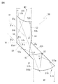
- FIG. 4 and 5 are diagrams for explaining the light guide 50, which is a diagram schematically showing a cross section of the light guide 50 taken along the plane A in FIG. 3, and is incident on the light guide 50. It is a figure explaining the movement locus
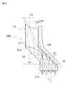
- FIG. 6 is a diagram for explaining light reflection and refraction at the light guide 50.
- FIG. 6A shows light reflection and refraction at the reflection surface 52b, and shows the relationship between the critical angle ⁇ c and the incident angle ⁇ 1.
- (B) is a diagram for explaining the refraction of light on the incident surface 510, and (c) is a diagram for explaining the refraction of light on the exit surface 530.
- FIG. 7 is a diagram for explaining the movement trajectory of incident light inside the light guide 50.
- FIG. 6 is a diagram schematically showing a cross section of the light guide 50 taken along the plane A in FIG. 3, and is incident on the light guide 50. It is a figure explaining the movement locus
- FIG. 7A is a diagram showing the case of the light guide 50 according to the embodiment. These are the figures which showed the case of the light guide 80 (prism) concerning the prior art example in which the entrance plane and the output surface are each flat surfaces.
- the light guide 50 is shown together with the light shielding wall 123 and the blocking wall 124 in which the light guide 50 is fixed to the inner surface.
- the light shielding wall 123 and the blocking wall 124 are shown with a gap.
- the light guide 50 includes an incident part 51 into which light from the light source L is incident, and a guiding part 52 that guides the light incident from the incident part 51 to the emitting part 53 while reflecting most of the light.
- the light emitting unit 53 that irradiates the light that has reached through the guiding unit 52 toward the key top 110 is integrally formed.
- the incident portion 51 is provided to face the light source L in the axial direction of the axis X1 parallel to the axis X (see FIG.
- the surface of the incident portion 51 facing the light source L (incident surface 510) is It is formed in a curved surface protruding to the light source L side.
- the incident portion 51 is positioned outside the emitting portion 53 in the radial direction of the axis X1 and emits in the axial direction of the axis X1 in order to receive light emitted by the light source L located outside the operation detecting portion 15. It is located below the substrate 30 from the portion 53 (see FIG. 2).
- the incident part 51 is made of a material having a refractive index n1 larger than the refractive index n2 of air, the light irradiated from the light source L and reaching the incident part 51 is not reflected by the incident surface 510.
- the incident surface 510 is formed in a curved shape protruding to the light source L side, and the surface area of the incident surface 510 is increased, thereby increasing the chance of contact with the light emitted from the light source L, and the incident portion.
- the amount of light incident from 51 is increased. As shown in FIG.
- the incident surface 510 has a predetermined width W1 in the radial direction of the axis X1, and one side 510a of the incident surface 510 is connected to the lower end of the reflecting surface 52b of the guiding portion 52.
- the reflecting surface 52b is a flat surface inclined by a predetermined angle ⁇ y with respect to the normal line Y1 of the axis X1, and this reflecting surface 52b crosses the upper side of the incident surface 510 in the radial direction of the axis X1 and the other surfaces of the incident surface 510. It is connected to the side surface portion 53b of the emitting portion 53 on the axis X1 side with respect to the side 510b.
- the reflecting surface 52 b is positioned above the incident portion 51, and almost all of the light from the light source L incident from the incident surface 510 reaches the reflecting surface 52 b of the guiding portion 52.
- the guiding portion 52 is provided to guide the light incident on the incident portion 51 to the emitting portion 53, and includes a reflecting surface 52a and a reflecting surface 52b inclined by a predetermined angle ⁇ y with respect to the normal line Y1 of the axis X1. ing.
- These reflective surfaces 52a and 52b are provided in a positional relationship parallel to each other.
- the reflective surface 52a is positioned on the lower side of the substrate 30 and the reflective surface 52b is positioned on the upper side of the key button 11. ing.
- the guide portion 52 has a predetermined thickness W3 in a direction orthogonal to the reflecting surfaces 52a and 52b.
- the thickness W3 of the guide portion 52 enters the light guide 50 from the incident portion 51.
- the thickness is set such that the light moves toward the emitting portion 53 after being reflected by the reflecting surface 52b and the reflecting surface 52a.
- the crossing angle predetermined angles ⁇ y, ( ⁇ y ⁇ ⁇ c)
- the curvature radius R1 of the incident surface 510 see FIG.
- the critical angle ⁇ c is a minimum incident angle at which incident light can be totally reflected by the reflecting surface 52b (an angle based on the normal line V2 of the reflecting surface 52b). is there.
- the incident angle ⁇ 1 and the refractive angle ⁇ 2 of the light with respect to the reflective surface 52b The relationship based on Snell's law is expressed by the following formula (1).
- the minimum incident angle when the light reaching the reflecting surface 52b is totally reflected by the reflecting surface 52b (the angle ⁇ 1 when the critical angle ⁇ c: ⁇ 2 is 90 °, and the normal V2 of the reflecting surface 52b) ) Is represented by the following formula (2). Therefore, in the embodiment, based on the refractive index n1 of the light guide 50 and the refractive index n2 of air, the critical angle ⁇ c at the reflecting surface 52b is calculated from the above equation (2) and refracted at the incident surface 510. Thus, the radius of curvature R1 of the incident surface 510 is set so that many incident angles ⁇ 1 of the light (refracted light L2) reaching the reflecting surface 52b are equal to or larger than the critical angle ⁇ c.
- the light irradiated from the light source L and reaching the incident surface 510 ((b) in FIG. 6, the incident light L1) is a material whose refractive index n1 is higher than the refractive index n2 of the air by the incident portion 51. Therefore, after refracting at an incident angle ⁇ 2 with respect to the incident surface 510 and a refraction angle ⁇ 1 determined according to the refractive indexes n1 and n2, the inside of the incident part 51 proceeds toward the reflecting surface 52b. Therefore, in the embodiment, as shown in FIG.
- the incident angle of the light (refracted light L2) refracted at the incident point P1 with respect to the reflecting surface 52b is set.
- the incident angle ⁇ 2 and the refraction angle ⁇ 1 of the light at the incident point P1 required to be larger than the critical angle ⁇ c are based on the position of the light source L and the crossing angle ⁇ y of the reflecting surface 52b with respect to the normal line Y1 of the axis X1. To calculate.
- a normal line V1 that realizes the calculated incident angle ⁇ 2 and refraction angle ⁇ 1 is obtained for each incident point P1, and a minute line segment of a tangent line orthogonal to the normal line V1 at each incident point P1 is obtained with respect to the axis X1.
- Light refracted at the incident surface 510 by being connected to the direction along the imaginary line Lm extending in the radial direction and the direction orthogonal to both the axis X1 and the imaginary line Lm (direction orthogonal to the paper surface in FIG. 6B).
- the three-dimensional shape of the incident surface 510 that can reflect almost all of the light from the reflecting surface 52b and the radius of curvature R1 are set. As a result, as shown in FIG.
- most of the light (refracted light L2) refracted at the incident surface 510 and whose traveling direction is changed to the direction toward the reflecting surface 52b is a critical angle. Since the light is incident on the reflecting surface 52b at an incident angle ⁇ 1b ( ⁇ 1b ⁇ ⁇ c) larger than ⁇ c, most of the light refracted by the incident surface 510 (refracted light L2) is not refracted by the reflecting surface 52b. Total reflection is performed on the 52a side.
- a part of the light (refracted light L2) refracted at the incident surface 510 is refracted at the reflecting surface 52b at an incident angle ⁇ 1a ( ⁇ 1a ⁇ ⁇ c) smaller than the critical angle ⁇ c and leaks out of the light guide 50.
- FIG. 4, (a), refracted light L6 The light (reflected light L3) that is reflected by the reflecting surface 52b and whose traveling direction is changed to the direction toward the reflecting surface 52a (the reflected light L3) is provided in parallel with the reflecting surface 52b.
- the light is incident on the reflecting surface 52a at the same incident angle ⁇ 1b as when the light is totally reflected by 52b (FIG. 4, (a), reflected light L3).
- the emission part 53 extends in a direction away from the incidence part 51 along the axis X1, and side surfaces 53a and 53b of the emission part 53 parallel to each other are provided in parallel to the axis X1.
- the emitting portion 53 has a predetermined width W2 in the radial direction of the axis X1, and the upper end surface thereof is an emitting surface 530 that is recessed in a curved shape in a direction away from the key button 11.
- the lower end 53a1 of the side surface portion 53a is connected to the reflection surface 52a of the guide portion 52 described above, and the side surface portion 53a and the reflection surface 52a are normal to the side surface portion 53a (same as the normal line Y1 of the axis X1). As a reference, they intersect each other at a predetermined angle ⁇ y.
- the side surface portion 53a is located on the moving direction side of the light reflected by the reflecting surface 52a (reflected light L4) so that a part of the light reflected by the reflecting surface 52a (reflected light L4c) reaches. It has become.
- the intersecting angle ⁇ x with respect to the axis X1 of the reflecting surface 52a is set so that the intersecting angle ⁇ y between the normal line Y1 of the side surface portion 53a and the reflecting surface 52a is equal to or larger than the critical angle ⁇ c. ⁇ y ⁇ ⁇ c).
- the incident angle ⁇ z at the side surface portion 53a of the reflected light L4c reflected by the reflection surface 52a and reaching the side surface portion 53a is the difference between the reflection surface 52a and the normal line Y1 of the side surface portion 53a.
- Incident light is incident at an incident angle ⁇ z that is always larger than the intersection angle ⁇ y.
- the incident angle ⁇ z of the light (reflected light L4c) reflected by the incident surface 52a and reaching the side surface portion 53a is Since the incident angle is larger than the critical angle ⁇ c at the side surface portion 53a, in the embodiment, all of the light (reflected light L4c) reaching the side surface portion 53a is totally reflected by the side surface portion 53a.
- the traveling direction is changed to a direction toward the emission surface 530. Note that (1) light reflected by the side surface portion 53a and (2) light reflected by the reflection surface 52a may reach the opposite side surface portion 53b.
- the side surface portion 53a reflects light incident on the side surface portion 53a at a critical angle ⁇ c or more, and the side surface portion 53a and the side surface portion 53b are provided in parallel to each other. Therefore, the incident angles of the light reflected by the side surface portion 53a and reaching the side surface portion 53b with respect to the side surface portion 53b are all equal to or larger than the critical angle ⁇ c. Therefore, all of the light reflected by the side surface portion 53a and reaching the side surface portion 53b is totally reflected by the side surface portion 53b.
- the length Lx of the side surface portion 53b relative to the normal line Y1 is shorter than the length of the side surface portion 52a, and light reflected by the side surface portion 52a (reflected light L4c). ) Is prevented from entering the side surface portion 53b.
- ⁇ is an incident angle with respect to the normal V2 of the reflection surface 52a of the light reaching the side surface portion 53b.
- the incident angle ⁇ of the reflected light L3 with respect to the normal V2 of the reflecting surface 52a is not less than the critical angle ⁇ c ( ⁇ ⁇ ⁇ c). Then, ⁇ > ⁇ ⁇ ⁇ c, and the light reflected by the reflecting surface 52a and incident on the side surface portion 53b is also totally reflected by the side surface portion 53b. As described above, when the light traveling in the light guide 50 reaches the side surface portion 53b, all of the reached light is totally reflected by the side surface portion 53b and guided to the emission surface 530 side. In the light guide 50, light does not leak from the side surface portion 53b toward the outside of the light guide 50.
- the light reflected at the angle ⁇ travels through the emission part 53 and reaches the emission surface 530.
- the light guide 50 is made of a material having a refractive index n1 larger than the refractive index n2 of air, the light that has moved through the emission part 53 and reached the emission surface 530 is emitted from the light emission surface 530.
- the incident angle at the emission surface 530 is The shape and the radius of curvature R2 are set so as to be equal to or smaller than the critical angle ⁇ c.
- the incident angle ⁇ 1 is smaller than the critical angle ⁇ c and the refraction angle ⁇ 2 is intended to refract light at each light incident point P2 on the exit surface 530.
- a minute line segment of the tangent perpendicular to the normal line V3 at each incident point P2 is defined along a virtual line Lm extending in the radial direction of the axis line X1;
- the light reaching the emission surface 530 is desired in a desired direction (for example, desired in the key top 110).
- the three-dimensional shape of the exit surface 530 and the radius of curvature R2 of the exit surface 530 are determined. As shown in FIG.
- the emission surface 530 of the emission part 53 in the housing 12 is located in an opening 121 a that opens in contact with the outer periphery of the support part 122.
- the opening 121a is located at a position facing the space 114 of the key button 11 and hidden at the key button 11 when viewed from above.
- a blocking wall portion 124 is provided to prevent the light passing through the opening 121a from diffusing outward in the radial direction of the axis X.
- the blocking wall portion 124 extends in the vertical direction along the side surface portion 53 b of the emitting portion 53, and the upper end 124 a of the blocking wall portion 124 is more key than the emitting surface 530.
- a light shielding wall 123 is integrally provided at a lower portion of the blocking wall 124. The light shielding wall 123 extends downward on the incident portion 51 side along the reflecting surface 52b of the guiding portion 52, and has a width Wa (see FIG. 1B) covering the entire reflecting surface 53b. Have.
- the light shielding wall portion 123 is formed of a material that does not transmit light (refracted light L6) leaking from the reflecting surface 52b to the outside of the guiding portion 52. If the light leaking from the reflecting surface 52b leaks outside the housing 12 (see FIG. 2), the surroundings of the housing 12 are illuminated by the leaked light, so that this situation does not occur.
- the movement trajectory of the light incident on the light guide 50 will be described by taking as an example the case where the number of the light sources L is four. As shown in FIG. 7A, the light from the light source L that has reached the incident surface 510 has a refractive index n1 of the material constituting the incident portion 51 larger than the refractive index n2 of air.
- the light enters the incident portion 51 as refracted light L2 without being reflected.
- the reflecting surface 52b is positioned above the incident portion 51, and the curved incident surface 510 of the incident portion 51 refracts the light that has reached the incident surface 510, and the traveling direction thereof is a direction toward the reflecting surface 52b. Therefore, most of the light from the light source L incident from the incident portion 51 reaches the reflecting surface 52b.
- light having an incident angle ⁇ 1 with respect to the reflecting surface 52b larger than the critical angle ⁇ c is reflected by the reflecting surface 52b, and the traveling direction thereof is in a direction toward the reflecting surface 52a. It will be changed (reflected light L3).
- the light (reflected light L3) that has been reflected by the reflecting surface 52b and whose traveling direction is changed to the direction toward the reflecting surface 52a is reflected by the reflecting surface 52a and the reflecting surface 52b.
- the light enters the reflecting surface 52a at the same incident angle ⁇ 1b as the incident angle ⁇ 1b with respect to 52b (see FIG. 4). Since the incident angle ⁇ 1b is larger than the critical angle ⁇ c, the light that has reached the reflecting surface 52a is totally reflected on the reflecting surface 52a, and its traveling direction is changed to a direction toward the emitting portion 53. (Reflected light L4). A part of the light (reflected light L4c) reflected by the reflecting surface 52a reaches the side surface 53a of the emitting part 53.
- the intersection angle ⁇ y (see FIGS. 4 and 5) of the side surface portion 53a, the reflection surface 52a, and the normal line Y1 of the axis X1 is set to be equal to or larger than the critical angle ⁇ c at the side surface portion 53a. Since the incident angle ⁇ z of the light reflected by the reflecting surface 52a (reflected light L4c) to the side surface portion 53a is larger than the critical angle ⁇ c, the light reaching the side surface portion 53a is totally reflected by the side surface portion 53a, The traveling direction is changed to a direction toward the emission surface 530 ( ⁇ z> ⁇ y ⁇ ⁇ c).
- the light (refracted light L7) that is refracted by the side surface portion 53a of the emitting portion 53 and leaks to the outside becomes a very small amount of light that reaches the side surface portion 53a after being reflected by the reflecting surface 52b (FIG. 7). (See (a)).
- the light reflected by the reflective surface 52a reflected light L4
- the light reflected by the side surface portion 53a reflected light L4c
- the light incident from the incident surface 510 (refracted light L2b)
- the light (see FIG. 5) reflected from the side surface portion 53b at the reflection angle ⁇ finally arrives.
- the exit surface 530 is shaped so that these lights are refracted and the traveling direction of these lights refracted by the exit surface 530 is directed to a desired position of the key top 110.
- the refracted light L5 emitted from the emission surface 530 illuminates a desired position of the key top 110.
- the incident surface 510 has a curved shape protruding toward the light source L side. is not.
- the light reaching the reflecting surface 82b includes a lot of light having an incident angle smaller than the critical angle ⁇ c with respect to the reflecting surface 82b. Therefore, more light than in the case of the light guide 50 described above is refracted by the reflecting surface 82b and leaks outside the light guide 80 ((b) in FIG. 7, refracted light L6). Therefore, the amount of light reflected by the reflecting surface 82b and guided to the emitting portion 83 side is smaller than that of the light guide 50 described above, so that the amount of light that illuminates the key top 110 is reduced.
- the light guide 80 since the light shielding member that covers the reflection surface 82b of the guide portion 82 is not provided, the light that is refracted by the reflection surface 82b and leaks outside the light guide 80 is not blocked. Since it leaks out of the housing, an unscheduled portion around the key button 11 is illuminated. Further, the exit surface 830 of the light guide 80 is a flat surface, and the traveling direction of the light (refracted light L5) refracted by the exit surface 530 is the key, like the exit surface 530 of the light guide 50 described above. The desired position of the top 110 is not adjusted to illuminate.
- the light emitted from the emission surface 830 cannot be sufficiently used for illumination of the key top 110, and as a result, the amount of light that illuminates a desired portion (for example, a printing unit) of the key top 110 is reduced.
- the improvement in the visibility of character information printed on 110 becomes insufficient.
- the key button 11 supported by the housing 12 on the axis X along the operation direction of the key button 11 is opposed to the operation detection unit 15 when viewed from the axis direction of the axis X.
- a light source L is provided outside the operation detection unit 15 on 30 and a light guide 50 that guides light from the light source L to the key top 110 of the key button 11 is made of a material having a higher refractive index than air. And the light guide 50 is provided on the housing 12.
- An incident portion 51 disposed opposite to the light source L in the axial direction of the axis X
- an emission portion 53 disposed opposite to the key top 110 at a position hidden from the key button 11 when viewed from the axial direction of the axis X
- an incident portion A light guide unit 52 that guides the light from the light source L incident from the light source L to the emission unit 53 while reflecting the light.
- the light incident surface 510 that faces the light source L of the light incident unit 51 is disposed on the light source L side.
- the keyboard is configured to have a protruding curved shape. If comprised in this way, since the refractive index n1 of the light guide 50 is larger than the refractive index n2 of air, the light which irradiated from the light source L and reached
- the incident surface 510 which is a surface facing the light source L of the incident portion 51, is formed in a curved surface protruding toward the light source L and the surface area of the incident surface 510 is increased, the incident surface 510 of light from the light source L enters the incident surface 510.
- the guide portion 52 of the light guide 50 has a reflection surface 52b (first boundary surface) through which light (refracted light L2) refracted at the incident surface 510 and incident on the incident portion 51 reaches.
- the incident surface 510 has a critical angle ⁇ c of the light at the reflecting surface 52b in which the incident angle of the light refracted by the incident surface 510 with respect to the reflecting surface 52b is determined according to the refractive index n1 of the light guide 50 and the refractive index n2 of air.
- the structure is formed with a radius of curvature R1 that can enter at an incident angle larger than (the minimum angle with respect to the normal line V2 of the reflecting surface 52b when the light reaching the reflecting surface 52b is totally reflected).
- the critical angle is about 45.60 ° to 38.70 °.
- the radius of curvature R1 of 510 is, for example, not less than 2.6 mm and not more than 2.8 mm.
- the incident portion 51 and the emission portion 53 are disposed at positions offset in the axial direction of the axis X, and the emission portion 53 is positioned closer to the axis X than the incident portion 51 in the radial direction of the axis X.
- the reflecting surface 52b first boundary surface
- the reflecting surface 52a first light that reflects the light (reflected light L3) reflected by the reflecting surface 52b toward the emitting portion 53. 2
- the reflecting surface 52a is located closer to the incident portion 51 than the reflecting surface 52b, and the side surface portion of the emitting portion 53 connected to the reflecting surface 52a.
- the crossing angle ⁇ y between 53a and the normal line Y1 of the axis X1 is set to be equal to or greater than the critical angle ⁇ c of light at the side surface portion 53a. If comprised in this way, the reflective surface 52a is provided in parallel with the reflective surface 52b in the light (reflected light L3) which the reflective surface 52b reflected and the advancing direction was changed to the direction which goes to the reflective surface 52a. Therefore, the light is incident on the reflecting surface 52a at the same incident angle ⁇ 1b as when the light is totally reflected by the reflecting surface 52b (FIG. 4, (a), reflected light L3).
- the incident angle ⁇ z of the light (reflected light L4c) reflected by the reflecting surface 52a and reaching the side surface portion 53a is The incident angle is larger than the critical angle ⁇ c at 53a. Thereby, all of the light (reflected light L4c) that has reached the side surface portion 53a is totally reflected by the side surface portion 53a, and its traveling direction is changed to the direction toward the emission surface 530. Light leakage from the side surface portion 53a can be suppressed, and the amount of light emitted from the emission surface 530 toward the key top 110 can be increased.
- the reflecting surface 52a and the reflecting surface 52b are arranged in parallel, and the guiding unit 52 is configured as a so-called rhomboid prism, which is suitable for illuminating the key top 110 with light incident from the incident unit 51. Since it can be translated to a position (a position corresponding to the emission unit 53), the light from the light source L arranged outside the operation detection unit 15 is emitted from the key button 11 positioned above the operation detection unit 15.
- the key top 110 can be appropriately illuminated without increasing the size of the housing 12 that supports the key button 11. Further, the light can be guided from the incident portion 51 located outside in the radial direction of the axis X to the emitting portion 53 located inside by reflecting light at least once between the reflecting surfaces 52a and 52b parallel to each other. Therefore, it is possible to appropriately illuminate the key top 110 without greatly changing the shape of the housing 12 or changing the arrangement of the operation detection unit 15. Furthermore, since the reflecting surface 52a and the reflecting surface 52b are arranged in parallel, the amount of light totally reflected increases, so that light transmission efficiency can be gained.
- the reflection surface 52b is provided with a light shielding wall portion 123 (light shielding portion) that blocks light that is refracted by the reflection surface 52b and leaks to the outside of the light guide 50. If comprised in this way, since the spreading
- the emission surface 530 that faces the key top 110 of the emission part 53 is configured to have a curved shape that is recessed in a direction away from the key top 110.
- a configuration in which the traveling direction of the refracted light is formed with a radius of curvature R2 in a direction toward a desired range of the key top is adopted.
- the radius of curvature R2 of the emission surface 530 according to the embodiment is, for example, 2.2 mm or more and 3.0 mm or less.
- the housing 12 has an opening 121a through which light refracted by the emission surface 530 of the emission part 53 and emitted to the outside of the light guide 50 passes, and the opening 121a is formed at the side edge of the opening 121a. Is provided with a blocking wall 124 (blocking wall) for blocking the diffusion of the axis X in the radial direction of the axis X.
- the blocking wall 124 is a peripheral wall of the key button 11.
- the configuration is such that it is inserted inside the portion 111. If comprised in this way, it will be suitable for the light radiate
- the housing 12 is formed of a transparent resin material.
- the light shielding wall portion 123 that blocks light that is refracted by the reflection surface 52b and leaks to the outside of the light guide 50 is provided in the housing 12 is illustrated. And the light shielding wall 123 may be omitted. In this case, light is leaked to the outside of the housing 12 by providing a material layer that absorbs light (refracted light) that is refracted by the reflecting surface 52b and leaks to the outside on the outer periphery of the reflecting surface 52b of the guiding portion 52. It can be suitably prevented from taking out.
- FIGS. 8 and 9 are diagrams illustrating a light guide 50A according to a modification.
- the incident surface 510 of the incident portion 51 has a curved shape that protrudes toward the light source L, and the curved surface shape in which the emission surface 530 of the emission portion 53 is recessed concavely in a direction away from the key top 110.
- the incident surface 510 of the incident portion 51 has a curved surface shape protruding toward the light source L side, and the emission of the emission portion 53. You may employ
- diffusion of the light irradiated from the output surface 530 can be prevented. Therefore, the diffusion of light that is refracted by the reflecting surface 52b of the guiding portion 52 and leaks outside the guiding portion 52 is blocked by the light shielding wall portion 123. 12 side surfaces etc.) can be prevented from being illuminated.
- FIG. 10 is a diagram illustrating a light guide 50B according to another modification. Furthermore, a light guide 50B is used in which the incident surface 510 of the incident portion 51 is a flat surface and the emission surface 530 of the emission portion 53 has a curved shape that is recessed concavely in a direction away from the key top 110.
- the emission surface 530 facing the key top 110 of the emission portion 53 is formed in a curved shape that is recessed in a direction away from the key top 110, and the emission surface 530 passes through the emission portion 53.
- the light reaching the exit surface 530 enters at an angle that is refracted by the exit surface 530 (the critical angle ⁇ c or less), and the traveling direction of the refracted light is a curvature radius R2 that is a direction toward a desired range of the key top. It was set as the formed structure. With this configuration, the light that has reached the emission surface 530 can be guided to the desired range of the key top 110 to illuminate the key top 110, so even if the amount of light that reaches the emission surface 530 decreases, Since the reduced amount of light can be canceled by guiding the light, it is possible to suitably prevent the visibility of the key top 110 from being lowered.
- the critical angle ⁇ c or less the traveling direction of the refracted light
- the present invention provides a keyboard with excellent visibility that can be used even in a dark place, since it is possible to prevent the visibility from being insufficient due to insufficient light amount for illuminating the key top.
Abstract
Priority Applications (4)
| Application Number | Priority Date | Filing Date | Title |
|---|---|---|---|
| US15/555,453 US10217578B2 (en) | 2015-03-04 | 2016-02-25 | Keyboard |
| CN201680013653.0A CN107408470B (zh) | 2015-03-04 | 2016-02-25 | 键盘 |
| EP16758984.5A EP3267459B1 (fr) | 2015-03-04 | 2016-02-25 | Clavier |
| KR1020177024602A KR101904930B1 (ko) | 2015-03-04 | 2016-02-25 | 키보드 |
Applications Claiming Priority (2)
| Application Number | Priority Date | Filing Date | Title |
|---|---|---|---|
| JP2015-042137 | 2015-03-04 | ||
| JP2015042137A JP6502706B2 (ja) | 2015-03-04 | 2015-03-04 | キーボード |
Publications (1)
| Publication Number | Publication Date |
|---|---|
| WO2016140291A1 true WO2016140291A1 (fr) | 2016-09-09 |
Family
ID=56847490
Family Applications (1)
| Application Number | Title | Priority Date | Filing Date |
|---|---|---|---|
| PCT/JP2016/056516 WO2016140291A1 (fr) | 2015-03-04 | 2016-02-25 | Clavier |
Country Status (7)
| Country | Link |
|---|---|
| US (1) | US10217578B2 (fr) |
| EP (1) | EP3267459B1 (fr) |
| JP (1) | JP6502706B2 (fr) |
| KR (1) | KR101904930B1 (fr) |
| CN (1) | CN107408470B (fr) |
| TW (1) | TWI681423B (fr) |
| WO (1) | WO2016140291A1 (fr) |
Families Citing this family (4)
| Publication number | Priority date | Publication date | Assignee | Title |
|---|---|---|---|---|
| US10684699B2 (en) * | 2018-08-01 | 2020-06-16 | Lite-On Electronics (Guangzhou) Limited | Illuminating keyboard |
| DE102019209504A1 (de) * | 2019-06-28 | 2020-12-31 | Robert Bosch Gmbh | Lichtleitelement für eine Beleuchtungseinrichtung |
| CN112490038A (zh) * | 2020-10-30 | 2021-03-12 | 深圳市吉迩科技有限公司 | 一种按键导光装置、方法及气溶胶产生装置 |
| US11469060B1 (en) | 2021-04-30 | 2022-10-11 | Logitech Europe S.A. | Light guide for a keyboard |
Citations (6)
| Publication number | Priority date | Publication date | Assignee | Title |
|---|---|---|---|---|
| JPS56154722U (fr) * | 1980-04-21 | 1981-11-19 | ||
| JPH0418884U (fr) * | 1990-06-04 | 1992-02-17 | ||
| JPH0446329U (fr) * | 1990-08-22 | 1992-04-20 | ||
| JP2001216070A (ja) * | 2000-01-31 | 2001-08-10 | Topre Corp | キーボード |
| JP2002289058A (ja) * | 2001-03-26 | 2002-10-04 | Nec Eng Ltd | キースイッチ |
| JP2015038891A (ja) * | 2014-11-21 | 2015-02-26 | 東プレ株式会社 | キーボードスイッチ |
Family Cites Families (11)
| Publication number | Priority date | Publication date | Assignee | Title |
|---|---|---|---|---|
| JPS56154722A (en) | 1980-05-01 | 1981-11-30 | Hideo Chishima | Device for slidably mounting article to guide bar |
| NL8801274A (nl) * | 1988-05-18 | 1989-12-18 | Philips Nv | Gerichte optische signalering. |
| JP3038792B2 (ja) | 1990-05-11 | 2000-05-08 | ソニー株式会社 | テレビジョン信号の補間回路 |
| JP2620891B2 (ja) | 1990-06-13 | 1997-06-18 | 健一 柿崎 | スクリーン兼用建造物壁面形成方法、およびそれ用の壁面構成部材 |
| JPH06242729A (ja) | 1993-02-16 | 1994-09-02 | Matsushita Electric Ind Co Ltd | 表示装置 |
| JP2002108539A (ja) * | 2000-09-26 | 2002-04-12 | Alps Electric Co Ltd | キーボード装置 |
| DE102005015814B4 (de) * | 2005-04-06 | 2007-06-28 | Siemens Ag Österreich | Formteil als optischer Lichtleiter |
| JP5302825B2 (ja) * | 2009-08-28 | 2013-10-02 | 富士通コンポーネント株式会社 | バックライト機能付きキーボード |
| JP5656461B2 (ja) | 2010-06-14 | 2015-01-21 | 日東光学株式会社 | 発光装置 |
| KR20130122811A (ko) * | 2012-05-01 | 2013-11-11 | 현대모비스 주식회사 | 차량용 멀티미디어 기기의 볼륨노브 |
| DE102012210357B4 (de) | 2012-06-20 | 2019-07-18 | Continental Automotive Gmbh | Elektronischer Schlüssel für ein Fahrzeug |
-
2015
- 2015-03-04 JP JP2015042137A patent/JP6502706B2/ja active Active
-
2016
- 2016-02-25 CN CN201680013653.0A patent/CN107408470B/zh active Active
- 2016-02-25 WO PCT/JP2016/056516 patent/WO2016140291A1/fr active Application Filing
- 2016-02-25 EP EP16758984.5A patent/EP3267459B1/fr active Active
- 2016-02-25 US US15/555,453 patent/US10217578B2/en active Active
- 2016-02-25 KR KR1020177024602A patent/KR101904930B1/ko active IP Right Grant
- 2016-03-04 TW TW105106763A patent/TWI681423B/zh active
Patent Citations (6)
| Publication number | Priority date | Publication date | Assignee | Title |
|---|---|---|---|---|
| JPS56154722U (fr) * | 1980-04-21 | 1981-11-19 | ||
| JPH0418884U (fr) * | 1990-06-04 | 1992-02-17 | ||
| JPH0446329U (fr) * | 1990-08-22 | 1992-04-20 | ||
| JP2001216070A (ja) * | 2000-01-31 | 2001-08-10 | Topre Corp | キーボード |
| JP2002289058A (ja) * | 2001-03-26 | 2002-10-04 | Nec Eng Ltd | キースイッチ |
| JP2015038891A (ja) * | 2014-11-21 | 2015-02-26 | 東プレ株式会社 | キーボードスイッチ |
Non-Patent Citations (1)
| Title |
|---|
| See also references of EP3267459A4 * |
Also Published As
| Publication number | Publication date |
|---|---|
| US20180040440A1 (en) | 2018-02-08 |
| CN107408470A (zh) | 2017-11-28 |
| JP2016162666A (ja) | 2016-09-05 |
| EP3267459B1 (fr) | 2019-12-25 |
| KR20170107576A (ko) | 2017-09-25 |
| TW201707030A (zh) | 2017-02-16 |
| JP6502706B2 (ja) | 2019-04-17 |
| CN107408470B (zh) | 2019-08-06 |
| TWI681423B (zh) | 2020-01-01 |
| EP3267459A1 (fr) | 2018-01-10 |
| EP3267459A4 (fr) | 2018-10-24 |
| KR101904930B1 (ko) | 2018-10-05 |
| US10217578B2 (en) | 2019-02-26 |
Similar Documents
| Publication | Publication Date | Title |
|---|---|---|
| WO2016140291A1 (fr) | Clavier | |
| JP6257132B2 (ja) | 導光体装置 | |
| CN110300950B (zh) | 触摸感测系统中的光学耦合 | |
| WO2015151675A1 (fr) | Élément de commande de faisceau lumineux, dispositif luminescent, dispositif de source lumineuse de surface, et dispositif d'affichage | |
| KR20140067013A (ko) | 지침식 표시장치 | |
| JP2016157582A (ja) | 導光体および発光装置 | |
| EP2009659A1 (fr) | Interrupteur éclairé | |
| TW201414957A (zh) | 照明裝置 | |
| WO2019184789A1 (fr) | Dispositif de projection laser et terminal mobile | |
| CN113260908A (zh) | 显示装置、照明装置、导光部件及导光构造 | |
| JP6061397B2 (ja) | 照光装置 | |
| US11029527B2 (en) | Optical mouse and light pipe thereof, and optical component of optical navigation device | |
| JP2013109863A (ja) | 車両用灯具 | |
| JP5889956B2 (ja) | 照明構造および携帯式コンピュータ | |
| JP5638874B2 (ja) | 照明構造、照明方法および携帯式コンピュータ | |
| TWM473601U (zh) | 發光按鍵裝置 | |
| JP7467825B2 (ja) | 発光装置、照明装置及び光学部材 | |
| JP7204304B2 (ja) | 指針発光装置 | |
| EP3885649B1 (fr) | Structure de guidage de lumière circulaire et dispositif de guidage de lumière | |
| JP5912291B2 (ja) | 導光シートおよび加飾成形体 | |
| KR101181081B1 (ko) | 도광체 및 선형상 광원 장치 | |
| JP2021097015A (ja) | 車両用灯具 | |
| WO2017077617A1 (fr) | Élément optique | |
| KR20200007631A (ko) | 광학 소자 및 광학계 장치 | |
| JP2012134124A (ja) | 照明装置及びこれを備える液晶表示装置 |
Legal Events
| Date | Code | Title | Description |
|---|---|---|---|
| 121 | Ep: the epo has been informed by wipo that ep was designated in this application |
Ref document number: 16758984 Country of ref document: EP Kind code of ref document: A1 |
|
| REEP | Request for entry into the european phase |
Ref document number: 2016758984 Country of ref document: EP |
|
| ENP | Entry into the national phase |
Ref document number: 20177024602 Country of ref document: KR Kind code of ref document: A |
|
| WWE | Wipo information: entry into national phase |
Ref document number: 15555453 Country of ref document: US |
|
| NENP | Non-entry into the national phase |
Ref country code: DE |