WO2016140291A1 - Keyboard - Google Patents
Keyboard Download PDFInfo
- Publication number
- WO2016140291A1 WO2016140291A1 PCT/JP2016/056516 JP2016056516W WO2016140291A1 WO 2016140291 A1 WO2016140291 A1 WO 2016140291A1 JP 2016056516 W JP2016056516 W JP 2016056516W WO 2016140291 A1 WO2016140291 A1 WO 2016140291A1
- Authority
- WO
- WIPO (PCT)
- Prior art keywords
- light
- incident
- key button
- light source
- axis
- Prior art date
Links
Images


Classifications
-
- H—ELECTRICITY
- H01—ELECTRIC ELEMENTS
- H01H—ELECTRIC SWITCHES; RELAYS; SELECTORS; EMERGENCY PROTECTIVE DEVICES
- H01H13/00—Switches having rectilinearly-movable operating part or parts adapted for pushing or pulling in one direction only, e.g. push-button switch
- H01H13/70—Switches having rectilinearly-movable operating part or parts adapted for pushing or pulling in one direction only, e.g. push-button switch having a plurality of operating members associated with different sets of contacts, e.g. keyboard
- H01H13/83—Switches having rectilinearly-movable operating part or parts adapted for pushing or pulling in one direction only, e.g. push-button switch having a plurality of operating members associated with different sets of contacts, e.g. keyboard characterised by legends, e.g. Braille, liquid crystal displays, light emitting or optical elements
-
- H—ELECTRICITY
- H01—ELECTRIC ELEMENTS
- H01H—ELECTRIC SWITCHES; RELAYS; SELECTORS; EMERGENCY PROTECTIVE DEVICES
- H01H13/00—Switches having rectilinearly-movable operating part or parts adapted for pushing or pulling in one direction only, e.g. push-button switch
- H01H13/02—Details
-
- H—ELECTRICITY
- H01—ELECTRIC ELEMENTS
- H01H—ELECTRIC SWITCHES; RELAYS; SELECTORS; EMERGENCY PROTECTIVE DEVICES
- H01H13/00—Switches having rectilinearly-movable operating part or parts adapted for pushing or pulling in one direction only, e.g. push-button switch
- H01H13/02—Details
- H01H13/023—Light-emitting indicators
-
- H—ELECTRICITY
- H01—ELECTRIC ELEMENTS
- H01H—ELECTRIC SWITCHES; RELAYS; SELECTORS; EMERGENCY PROTECTIVE DEVICES
- H01H13/00—Switches having rectilinearly-movable operating part or parts adapted for pushing or pulling in one direction only, e.g. push-button switch
- H01H13/70—Switches having rectilinearly-movable operating part or parts adapted for pushing or pulling in one direction only, e.g. push-button switch having a plurality of operating members associated with different sets of contacts, e.g. keyboard
-
- G—PHYSICS
- G02—OPTICS
- G02B—OPTICAL ELEMENTS, SYSTEMS OR APPARATUS
- G02B6/00—Light guides; Structural details of arrangements comprising light guides and other optical elements, e.g. couplings
- G02B6/0001—Light guides; Structural details of arrangements comprising light guides and other optical elements, e.g. couplings specially adapted for lighting devices or systems
- G02B6/0011—Light guides; Structural details of arrangements comprising light guides and other optical elements, e.g. couplings specially adapted for lighting devices or systems the light guides being planar or of plate-like form
- G02B6/0013—Means for improving the coupling-in of light from the light source into the light guide
- G02B6/0015—Means for improving the coupling-in of light from the light source into the light guide provided on the surface of the light guide or in the bulk of it
- G02B6/0016—Grooves, prisms, gratings, scattering particles or rough surfaces
-
- H—ELECTRICITY
- H01—ELECTRIC ELEMENTS
- H01H—ELECTRIC SWITCHES; RELAYS; SELECTORS; EMERGENCY PROTECTIVE DEVICES
- H01H9/00—Details of switching devices, not covered by groups H01H1/00 - H01H7/00
- H01H9/18—Distinguishing marks on switches, e.g. for indicating switch location in the dark; Adaptation of switches to receive distinguishing marks
- H01H9/182—Illumination of the symbols or distinguishing marks
Definitions
- the present invention relates to a keyboard.
- Patent Document 1 discloses that light from a light source provided on a substrate is guided to a key top by a prism (light guide) provided inside the key button to illuminate the key top.
- Patent Document 1 the light incident from the incident end of the prism travels while reflecting inside the prism, and then exits from the exit end of the prism toward the key top to illuminate the key top. It is like that. However, since the prism cannot totally reflect the incident light, the incident light may leak from a place other than the exit end. For this reason, the amount of light for illuminating the key top is insufficient and the visibility may be insufficient, and it is required to further improve the visibility of the key buttons.
- the present invention includes a housing that supports a key button so that the key button can reciprocate in an operation direction of the key button, and a board on which an operation detection unit for the key button is provided, and the key button supported by the housing.
- a light source is provided outside the operation detection unit on the substrate, and a light guide that guides light from the light source to the key top of the key button is refracted from air.
- An incident portion that is formed of a material having a high rate and is provided in the housing, and the light guide is disposed opposite to the light source in the axial direction of the axis, An emission part disposed opposite to the key top at a position hidden by the key button as seen from the axial direction of the axis; A guiding portion that guides the light from the light source incident from the incident portion to the emission portion while reflecting the light, and a surface of the incident portion that faces the light source protrudes toward the light source. It was set as the keyboard characterized by having formed in.
- the refractive index of the light guide is larger than the refractive index of air
- the light irradiated from the light source and reaching the incident part is refracted without being reflected by the surface of the incident part, and the incident part From the inside of the light guide.
- Increasing the surface area of the incident part by forming the incident part facing the light source in a curved surface and increasing the surface area of the incident part results in an increase in the amount of light from the light source incident from the incident part. It is possible to secure the amount of light emitted toward the. Therefore, since it is possible to prevent the visibility from being insufficient due to insufficient light amount for illuminating the key top, it is possible to provide a keyboard with excellent visibility that can be used even in a dark place.
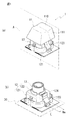
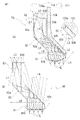
- FIG. 1 is a diagram for explaining a key 1 constituting a keyboard
- (a) is a perspective view of the key 1
- (b) is a state in which a key button 11 is removed from the key 1 shown in (a).
- FIG. 2 is a perspective view showing the plunger 13 supported by the housing 12 and the support portion 122 of the housing.
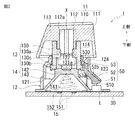
- FIG. 2 is a diagram illustrating a specific configuration of the key 1, and is a cross-sectional view of the key 1 cut along a plane A in FIG.
- the key button 11 side in FIG. 2 is described as the upper side
- the substrate 30 side is described as the lower side.
- the key 1 includes a key button 11 and a housing 12.
- the key button 11 is moved downward on the housing 12 side by a pressing operation of the key top 110 having a concave upper surface, and the key button 11 in the housing 12 is operated in the operation direction of the key button 11 (FIG. 2). In the vertical direction).
- the key button 11 has a key top 110, a peripheral wall portion 111 that surrounds the outer periphery of the key top 110 over the entire circumference, and a columnar shape that extends downward from the lower surface of the key top 110 to the substrate 30 side.
- the shaft portion 112 is provided.
- the shaft portion 112 is provided substantially at the center of the key top 110, and below the key top 110, a support portion 122 of the housing 12 described later is provided between the outer periphery of the shaft portion 112 and the inner periphery of the peripheral wall portion 111.
- An enterable space 114 is formed.
- a reinforcing wall 113 is provided by connecting the key top 110, the shaft portion 112, and the peripheral wall portion 111, and the rigidity strength of the key button 11 is secured by the reinforcing wall 113. Yes.
- characters, figures, symbols, and the like that mark the functions assigned to the key buttons 11 are printed.
- the key top 110 only the portion on which the characters, figures, symbols, etc.
- the key top 110 is formed of a translucent resin, and at least the outer surface is painted with a paint that does not transmit light.
- the key top 110 is printed with the characters, figures, symbols, and the like described above by removing the coating with a laser or the like. When the back surface of the key top 110 is illuminated, the light is transmitted through the printed portion. Symbols etc. are shining visually so as to be visible.
- a cylindrical base portion 130 of the plunger 13 is attached to the lower end side of the shaft portion 112 by external fitting.
- a rib 130a having a cross shape when viewed from the axial direction of the axis X is provided inside the base 130, and a flange portion 130b having a larger outer diameter than the base 130 is provided on the lower end side of the base 130.
- the plunger 13 passes through a cylindrical support portion 122 provided on the housing 12 from below the substrate 30 side, and the upper end of the base portion 130 of the plunger 13 is fitted on the shaft portion 112 outside the support portion 122. Thus, the plunger 13 and the key button 11 are connected.
- the key button 11 is provided so as to be reciprocally movable in the axis X direction by the housing 12 (support portion 122) via the plunger 13.
- the key button 11 has a size that covers the housing 12 when viewed from the operation direction of the key button 11 (axis direction of the axis X). The button 11 is hidden and cannot be visually recognized.
- the housing 12 includes an accommodating portion 121 that accommodates an operation detecting portion 15 that detects an operation of the key button 11, a cylindrical support portion 122 that supports the key button 11 so as to be capable of reciprocating above the operation detecting portion 15,
- a light guide 50 to be described later has a light shielding wall portion 123 fixed to the inner surface, and a blocking wall portion 124 extending upward from the upper end of the light shielding wall portion 123.
- the operation detection unit 15 accommodated in the accommodation unit 121 includes an electrode pair 151 and 151 that are spaced apart from each other on the upper surface of the substrate 30, and an elastic body 152 (conical shape) placed across the electrode pair 151 and 151. And a mounting portion 142 of the cup rubber 14 mounted on the substrate 30 is mounted on the elastic body 152.
- the cup rubber 14 has a trapezoidal shape, and the inside of the cup rubber 14 is a hollow portion 141 that accommodates the operation detection unit 15.
- the cup rubber 14 is formed of an elastic member such as rubber, and a pressing portion 130c of the plunger 13 assembled to the key button 11 is mounted on a mounting portion 142 having a cylindrical shape.
- the plunger 13 moves together with the key button 11 toward the substrate 30 when the key button 11 is pressed. Therefore, when the key button 11 is operated, the placement portion 142 pushed by the plunger 13 is displaced toward the substrate 30 while bending the leg portion 143, and the elastic body 152 is displaced toward the substrate 30 side. Thus, a change in capacitance is detected, and a pressing operation of the key button 11 is detected.
- the light source L is provided outside the operation detection unit 15, and the incident unit 51 of the light guide 50 is located above the light source L.
- a light emitting diode for example, is employed as the light source L.
- the light emitting diode used in this case may be a single color light emitting diode or a combination of light emitting diodes of a plurality of colors.
- a scattering member that scatters light in the light irradiation portion of the light emitting diode in order to increase the light incident area to the light guide 50.
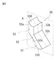
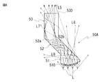
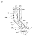
- FIG. 3 is a perspective view of the light guide 50 provided in the housing 12.
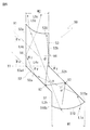
- FIG. 4 and 5 are diagrams for explaining the light guide 50, which is a diagram schematically showing a cross section of the light guide 50 taken along the plane A in FIG. 3, and is incident on the light guide 50. It is a figure explaining the movement locus
- FIG. 6 is a diagram for explaining light reflection and refraction at the light guide 50.
- FIG. 6A shows light reflection and refraction at the reflection surface 52b, and shows the relationship between the critical angle ⁇ c and the incident angle ⁇ 1.
- (B) is a diagram for explaining the refraction of light on the incident surface 510, and (c) is a diagram for explaining the refraction of light on the exit surface 530.
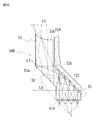
- FIG. 7 is a diagram for explaining the movement trajectory of incident light inside the light guide 50.
- FIG. 6 is a diagram schematically showing a cross section of the light guide 50 taken along the plane A in FIG. 3, and is incident on the light guide 50. It is a figure explaining the movement locus
- FIG. 7A is a diagram showing the case of the light guide 50 according to the embodiment. These are the figures which showed the case of the light guide 80 (prism) concerning the prior art example in which the entrance plane and the output surface are each flat surfaces.
- the light guide 50 is shown together with the light shielding wall 123 and the blocking wall 124 in which the light guide 50 is fixed to the inner surface.
- the light shielding wall 123 and the blocking wall 124 are shown with a gap.
- the light guide 50 includes an incident part 51 into which light from the light source L is incident, and a guiding part 52 that guides the light incident from the incident part 51 to the emitting part 53 while reflecting most of the light.
- the light emitting unit 53 that irradiates the light that has reached through the guiding unit 52 toward the key top 110 is integrally formed.
- the incident portion 51 is provided to face the light source L in the axial direction of the axis X1 parallel to the axis X (see FIG.
- the surface of the incident portion 51 facing the light source L (incident surface 510) is It is formed in a curved surface protruding to the light source L side.
- the incident portion 51 is positioned outside the emitting portion 53 in the radial direction of the axis X1 and emits in the axial direction of the axis X1 in order to receive light emitted by the light source L located outside the operation detecting portion 15. It is located below the substrate 30 from the portion 53 (see FIG. 2).
- the incident part 51 is made of a material having a refractive index n1 larger than the refractive index n2 of air, the light irradiated from the light source L and reaching the incident part 51 is not reflected by the incident surface 510.
- the incident surface 510 is formed in a curved shape protruding to the light source L side, and the surface area of the incident surface 510 is increased, thereby increasing the chance of contact with the light emitted from the light source L, and the incident portion.
- the amount of light incident from 51 is increased. As shown in FIG.
- the incident surface 510 has a predetermined width W1 in the radial direction of the axis X1, and one side 510a of the incident surface 510 is connected to the lower end of the reflecting surface 52b of the guiding portion 52.
- the reflecting surface 52b is a flat surface inclined by a predetermined angle ⁇ y with respect to the normal line Y1 of the axis X1, and this reflecting surface 52b crosses the upper side of the incident surface 510 in the radial direction of the axis X1 and the other surfaces of the incident surface 510. It is connected to the side surface portion 53b of the emitting portion 53 on the axis X1 side with respect to the side 510b.
- the reflecting surface 52 b is positioned above the incident portion 51, and almost all of the light from the light source L incident from the incident surface 510 reaches the reflecting surface 52 b of the guiding portion 52.
- the guiding portion 52 is provided to guide the light incident on the incident portion 51 to the emitting portion 53, and includes a reflecting surface 52a and a reflecting surface 52b inclined by a predetermined angle ⁇ y with respect to the normal line Y1 of the axis X1. ing.
- These reflective surfaces 52a and 52b are provided in a positional relationship parallel to each other.
- the reflective surface 52a is positioned on the lower side of the substrate 30 and the reflective surface 52b is positioned on the upper side of the key button 11. ing.
- the guide portion 52 has a predetermined thickness W3 in a direction orthogonal to the reflecting surfaces 52a and 52b.
- the thickness W3 of the guide portion 52 enters the light guide 50 from the incident portion 51.
- the thickness is set such that the light moves toward the emitting portion 53 after being reflected by the reflecting surface 52b and the reflecting surface 52a.
- the crossing angle predetermined angles ⁇ y, ( ⁇ y ⁇ ⁇ c)
- the curvature radius R1 of the incident surface 510 see FIG.
- the critical angle ⁇ c is a minimum incident angle at which incident light can be totally reflected by the reflecting surface 52b (an angle based on the normal line V2 of the reflecting surface 52b). is there.
- the incident angle ⁇ 1 and the refractive angle ⁇ 2 of the light with respect to the reflective surface 52b The relationship based on Snell's law is expressed by the following formula (1).
- the minimum incident angle when the light reaching the reflecting surface 52b is totally reflected by the reflecting surface 52b (the angle ⁇ 1 when the critical angle ⁇ c: ⁇ 2 is 90 °, and the normal V2 of the reflecting surface 52b) ) Is represented by the following formula (2). Therefore, in the embodiment, based on the refractive index n1 of the light guide 50 and the refractive index n2 of air, the critical angle ⁇ c at the reflecting surface 52b is calculated from the above equation (2) and refracted at the incident surface 510. Thus, the radius of curvature R1 of the incident surface 510 is set so that many incident angles ⁇ 1 of the light (refracted light L2) reaching the reflecting surface 52b are equal to or larger than the critical angle ⁇ c.
- the light irradiated from the light source L and reaching the incident surface 510 ((b) in FIG. 6, the incident light L1) is a material whose refractive index n1 is higher than the refractive index n2 of the air by the incident portion 51. Therefore, after refracting at an incident angle ⁇ 2 with respect to the incident surface 510 and a refraction angle ⁇ 1 determined according to the refractive indexes n1 and n2, the inside of the incident part 51 proceeds toward the reflecting surface 52b. Therefore, in the embodiment, as shown in FIG.
- the incident angle of the light (refracted light L2) refracted at the incident point P1 with respect to the reflecting surface 52b is set.
- the incident angle ⁇ 2 and the refraction angle ⁇ 1 of the light at the incident point P1 required to be larger than the critical angle ⁇ c are based on the position of the light source L and the crossing angle ⁇ y of the reflecting surface 52b with respect to the normal line Y1 of the axis X1. To calculate.
- a normal line V1 that realizes the calculated incident angle ⁇ 2 and refraction angle ⁇ 1 is obtained for each incident point P1, and a minute line segment of a tangent line orthogonal to the normal line V1 at each incident point P1 is obtained with respect to the axis X1.
- Light refracted at the incident surface 510 by being connected to the direction along the imaginary line Lm extending in the radial direction and the direction orthogonal to both the axis X1 and the imaginary line Lm (direction orthogonal to the paper surface in FIG. 6B).
- the three-dimensional shape of the incident surface 510 that can reflect almost all of the light from the reflecting surface 52b and the radius of curvature R1 are set. As a result, as shown in FIG.
- most of the light (refracted light L2) refracted at the incident surface 510 and whose traveling direction is changed to the direction toward the reflecting surface 52b is a critical angle. Since the light is incident on the reflecting surface 52b at an incident angle ⁇ 1b ( ⁇ 1b ⁇ ⁇ c) larger than ⁇ c, most of the light refracted by the incident surface 510 (refracted light L2) is not refracted by the reflecting surface 52b. Total reflection is performed on the 52a side.
- a part of the light (refracted light L2) refracted at the incident surface 510 is refracted at the reflecting surface 52b at an incident angle ⁇ 1a ( ⁇ 1a ⁇ ⁇ c) smaller than the critical angle ⁇ c and leaks out of the light guide 50.
- FIG. 4, (a), refracted light L6 The light (reflected light L3) that is reflected by the reflecting surface 52b and whose traveling direction is changed to the direction toward the reflecting surface 52a (the reflected light L3) is provided in parallel with the reflecting surface 52b.
- the light is incident on the reflecting surface 52a at the same incident angle ⁇ 1b as when the light is totally reflected by 52b (FIG. 4, (a), reflected light L3).
- the emission part 53 extends in a direction away from the incidence part 51 along the axis X1, and side surfaces 53a and 53b of the emission part 53 parallel to each other are provided in parallel to the axis X1.
- the emitting portion 53 has a predetermined width W2 in the radial direction of the axis X1, and the upper end surface thereof is an emitting surface 530 that is recessed in a curved shape in a direction away from the key button 11.
- the lower end 53a1 of the side surface portion 53a is connected to the reflection surface 52a of the guide portion 52 described above, and the side surface portion 53a and the reflection surface 52a are normal to the side surface portion 53a (same as the normal line Y1 of the axis X1). As a reference, they intersect each other at a predetermined angle ⁇ y.
- the side surface portion 53a is located on the moving direction side of the light reflected by the reflecting surface 52a (reflected light L4) so that a part of the light reflected by the reflecting surface 52a (reflected light L4c) reaches. It has become.
- the intersecting angle ⁇ x with respect to the axis X1 of the reflecting surface 52a is set so that the intersecting angle ⁇ y between the normal line Y1 of the side surface portion 53a and the reflecting surface 52a is equal to or larger than the critical angle ⁇ c. ⁇ y ⁇ ⁇ c).
- the incident angle ⁇ z at the side surface portion 53a of the reflected light L4c reflected by the reflection surface 52a and reaching the side surface portion 53a is the difference between the reflection surface 52a and the normal line Y1 of the side surface portion 53a.
- Incident light is incident at an incident angle ⁇ z that is always larger than the intersection angle ⁇ y.
- the incident angle ⁇ z of the light (reflected light L4c) reflected by the incident surface 52a and reaching the side surface portion 53a is Since the incident angle is larger than the critical angle ⁇ c at the side surface portion 53a, in the embodiment, all of the light (reflected light L4c) reaching the side surface portion 53a is totally reflected by the side surface portion 53a.
- the traveling direction is changed to a direction toward the emission surface 530. Note that (1) light reflected by the side surface portion 53a and (2) light reflected by the reflection surface 52a may reach the opposite side surface portion 53b.
- the side surface portion 53a reflects light incident on the side surface portion 53a at a critical angle ⁇ c or more, and the side surface portion 53a and the side surface portion 53b are provided in parallel to each other. Therefore, the incident angles of the light reflected by the side surface portion 53a and reaching the side surface portion 53b with respect to the side surface portion 53b are all equal to or larger than the critical angle ⁇ c. Therefore, all of the light reflected by the side surface portion 53a and reaching the side surface portion 53b is totally reflected by the side surface portion 53b.
- the length Lx of the side surface portion 53b relative to the normal line Y1 is shorter than the length of the side surface portion 52a, and light reflected by the side surface portion 52a (reflected light L4c). ) Is prevented from entering the side surface portion 53b.
- ⁇ is an incident angle with respect to the normal V2 of the reflection surface 52a of the light reaching the side surface portion 53b.
- the incident angle ⁇ of the reflected light L3 with respect to the normal V2 of the reflecting surface 52a is not less than the critical angle ⁇ c ( ⁇ ⁇ ⁇ c). Then, ⁇ > ⁇ ⁇ ⁇ c, and the light reflected by the reflecting surface 52a and incident on the side surface portion 53b is also totally reflected by the side surface portion 53b. As described above, when the light traveling in the light guide 50 reaches the side surface portion 53b, all of the reached light is totally reflected by the side surface portion 53b and guided to the emission surface 530 side. In the light guide 50, light does not leak from the side surface portion 53b toward the outside of the light guide 50.
- the light reflected at the angle ⁇ travels through the emission part 53 and reaches the emission surface 530.
- the light guide 50 is made of a material having a refractive index n1 larger than the refractive index n2 of air, the light that has moved through the emission part 53 and reached the emission surface 530 is emitted from the light emission surface 530.
- the incident angle at the emission surface 530 is The shape and the radius of curvature R2 are set so as to be equal to or smaller than the critical angle ⁇ c.
- the incident angle ⁇ 1 is smaller than the critical angle ⁇ c and the refraction angle ⁇ 2 is intended to refract light at each light incident point P2 on the exit surface 530.
- a minute line segment of the tangent perpendicular to the normal line V3 at each incident point P2 is defined along a virtual line Lm extending in the radial direction of the axis line X1;
- the light reaching the emission surface 530 is desired in a desired direction (for example, desired in the key top 110).
- the three-dimensional shape of the exit surface 530 and the radius of curvature R2 of the exit surface 530 are determined. As shown in FIG.
- the emission surface 530 of the emission part 53 in the housing 12 is located in an opening 121 a that opens in contact with the outer periphery of the support part 122.
- the opening 121a is located at a position facing the space 114 of the key button 11 and hidden at the key button 11 when viewed from above.
- a blocking wall portion 124 is provided to prevent the light passing through the opening 121a from diffusing outward in the radial direction of the axis X.
- the blocking wall portion 124 extends in the vertical direction along the side surface portion 53 b of the emitting portion 53, and the upper end 124 a of the blocking wall portion 124 is more key than the emitting surface 530.
- a light shielding wall 123 is integrally provided at a lower portion of the blocking wall 124. The light shielding wall 123 extends downward on the incident portion 51 side along the reflecting surface 52b of the guiding portion 52, and has a width Wa (see FIG. 1B) covering the entire reflecting surface 53b. Have.
- the light shielding wall portion 123 is formed of a material that does not transmit light (refracted light L6) leaking from the reflecting surface 52b to the outside of the guiding portion 52. If the light leaking from the reflecting surface 52b leaks outside the housing 12 (see FIG. 2), the surroundings of the housing 12 are illuminated by the leaked light, so that this situation does not occur.
- the movement trajectory of the light incident on the light guide 50 will be described by taking as an example the case where the number of the light sources L is four. As shown in FIG. 7A, the light from the light source L that has reached the incident surface 510 has a refractive index n1 of the material constituting the incident portion 51 larger than the refractive index n2 of air.
- the light enters the incident portion 51 as refracted light L2 without being reflected.
- the reflecting surface 52b is positioned above the incident portion 51, and the curved incident surface 510 of the incident portion 51 refracts the light that has reached the incident surface 510, and the traveling direction thereof is a direction toward the reflecting surface 52b. Therefore, most of the light from the light source L incident from the incident portion 51 reaches the reflecting surface 52b.
- light having an incident angle ⁇ 1 with respect to the reflecting surface 52b larger than the critical angle ⁇ c is reflected by the reflecting surface 52b, and the traveling direction thereof is in a direction toward the reflecting surface 52a. It will be changed (reflected light L3).
- the light (reflected light L3) that has been reflected by the reflecting surface 52b and whose traveling direction is changed to the direction toward the reflecting surface 52a is reflected by the reflecting surface 52a and the reflecting surface 52b.
- the light enters the reflecting surface 52a at the same incident angle ⁇ 1b as the incident angle ⁇ 1b with respect to 52b (see FIG. 4). Since the incident angle ⁇ 1b is larger than the critical angle ⁇ c, the light that has reached the reflecting surface 52a is totally reflected on the reflecting surface 52a, and its traveling direction is changed to a direction toward the emitting portion 53. (Reflected light L4). A part of the light (reflected light L4c) reflected by the reflecting surface 52a reaches the side surface 53a of the emitting part 53.
- the intersection angle ⁇ y (see FIGS. 4 and 5) of the side surface portion 53a, the reflection surface 52a, and the normal line Y1 of the axis X1 is set to be equal to or larger than the critical angle ⁇ c at the side surface portion 53a. Since the incident angle ⁇ z of the light reflected by the reflecting surface 52a (reflected light L4c) to the side surface portion 53a is larger than the critical angle ⁇ c, the light reaching the side surface portion 53a is totally reflected by the side surface portion 53a, The traveling direction is changed to a direction toward the emission surface 530 ( ⁇ z> ⁇ y ⁇ ⁇ c).
- the light (refracted light L7) that is refracted by the side surface portion 53a of the emitting portion 53 and leaks to the outside becomes a very small amount of light that reaches the side surface portion 53a after being reflected by the reflecting surface 52b (FIG. 7). (See (a)).
- the light reflected by the reflective surface 52a reflected light L4
- the light reflected by the side surface portion 53a reflected light L4c
- the light incident from the incident surface 510 (refracted light L2b)
- the light (see FIG. 5) reflected from the side surface portion 53b at the reflection angle ⁇ finally arrives.
- the exit surface 530 is shaped so that these lights are refracted and the traveling direction of these lights refracted by the exit surface 530 is directed to a desired position of the key top 110.
- the refracted light L5 emitted from the emission surface 530 illuminates a desired position of the key top 110.
- the incident surface 510 has a curved shape protruding toward the light source L side. is not.
- the light reaching the reflecting surface 82b includes a lot of light having an incident angle smaller than the critical angle ⁇ c with respect to the reflecting surface 82b. Therefore, more light than in the case of the light guide 50 described above is refracted by the reflecting surface 82b and leaks outside the light guide 80 ((b) in FIG. 7, refracted light L6). Therefore, the amount of light reflected by the reflecting surface 82b and guided to the emitting portion 83 side is smaller than that of the light guide 50 described above, so that the amount of light that illuminates the key top 110 is reduced.
- the light guide 80 since the light shielding member that covers the reflection surface 82b of the guide portion 82 is not provided, the light that is refracted by the reflection surface 82b and leaks outside the light guide 80 is not blocked. Since it leaks out of the housing, an unscheduled portion around the key button 11 is illuminated. Further, the exit surface 830 of the light guide 80 is a flat surface, and the traveling direction of the light (refracted light L5) refracted by the exit surface 530 is the key, like the exit surface 530 of the light guide 50 described above. The desired position of the top 110 is not adjusted to illuminate.
- the light emitted from the emission surface 830 cannot be sufficiently used for illumination of the key top 110, and as a result, the amount of light that illuminates a desired portion (for example, a printing unit) of the key top 110 is reduced.
- the improvement in the visibility of character information printed on 110 becomes insufficient.
- the key button 11 supported by the housing 12 on the axis X along the operation direction of the key button 11 is opposed to the operation detection unit 15 when viewed from the axis direction of the axis X.
- a light source L is provided outside the operation detection unit 15 on 30 and a light guide 50 that guides light from the light source L to the key top 110 of the key button 11 is made of a material having a higher refractive index than air. And the light guide 50 is provided on the housing 12.
- An incident portion 51 disposed opposite to the light source L in the axial direction of the axis X
- an emission portion 53 disposed opposite to the key top 110 at a position hidden from the key button 11 when viewed from the axial direction of the axis X
- an incident portion A light guide unit 52 that guides the light from the light source L incident from the light source L to the emission unit 53 while reflecting the light.
- the light incident surface 510 that faces the light source L of the light incident unit 51 is disposed on the light source L side.
- the keyboard is configured to have a protruding curved shape. If comprised in this way, since the refractive index n1 of the light guide 50 is larger than the refractive index n2 of air, the light which irradiated from the light source L and reached
- the incident surface 510 which is a surface facing the light source L of the incident portion 51, is formed in a curved surface protruding toward the light source L and the surface area of the incident surface 510 is increased, the incident surface 510 of light from the light source L enters the incident surface 510.
- the guide portion 52 of the light guide 50 has a reflection surface 52b (first boundary surface) through which light (refracted light L2) refracted at the incident surface 510 and incident on the incident portion 51 reaches.
- the incident surface 510 has a critical angle ⁇ c of the light at the reflecting surface 52b in which the incident angle of the light refracted by the incident surface 510 with respect to the reflecting surface 52b is determined according to the refractive index n1 of the light guide 50 and the refractive index n2 of air.
- the structure is formed with a radius of curvature R1 that can enter at an incident angle larger than (the minimum angle with respect to the normal line V2 of the reflecting surface 52b when the light reaching the reflecting surface 52b is totally reflected).
- the critical angle is about 45.60 ° to 38.70 °.
- the radius of curvature R1 of 510 is, for example, not less than 2.6 mm and not more than 2.8 mm.
- the incident portion 51 and the emission portion 53 are disposed at positions offset in the axial direction of the axis X, and the emission portion 53 is positioned closer to the axis X than the incident portion 51 in the radial direction of the axis X.
- the reflecting surface 52b first boundary surface
- the reflecting surface 52a first light that reflects the light (reflected light L3) reflected by the reflecting surface 52b toward the emitting portion 53. 2
- the reflecting surface 52a is located closer to the incident portion 51 than the reflecting surface 52b, and the side surface portion of the emitting portion 53 connected to the reflecting surface 52a.
- the crossing angle ⁇ y between 53a and the normal line Y1 of the axis X1 is set to be equal to or greater than the critical angle ⁇ c of light at the side surface portion 53a. If comprised in this way, the reflective surface 52a is provided in parallel with the reflective surface 52b in the light (reflected light L3) which the reflective surface 52b reflected and the advancing direction was changed to the direction which goes to the reflective surface 52a. Therefore, the light is incident on the reflecting surface 52a at the same incident angle ⁇ 1b as when the light is totally reflected by the reflecting surface 52b (FIG. 4, (a), reflected light L3).
- the incident angle ⁇ z of the light (reflected light L4c) reflected by the reflecting surface 52a and reaching the side surface portion 53a is The incident angle is larger than the critical angle ⁇ c at 53a. Thereby, all of the light (reflected light L4c) that has reached the side surface portion 53a is totally reflected by the side surface portion 53a, and its traveling direction is changed to the direction toward the emission surface 530. Light leakage from the side surface portion 53a can be suppressed, and the amount of light emitted from the emission surface 530 toward the key top 110 can be increased.
- the reflecting surface 52a and the reflecting surface 52b are arranged in parallel, and the guiding unit 52 is configured as a so-called rhomboid prism, which is suitable for illuminating the key top 110 with light incident from the incident unit 51. Since it can be translated to a position (a position corresponding to the emission unit 53), the light from the light source L arranged outside the operation detection unit 15 is emitted from the key button 11 positioned above the operation detection unit 15.
- the key top 110 can be appropriately illuminated without increasing the size of the housing 12 that supports the key button 11. Further, the light can be guided from the incident portion 51 located outside in the radial direction of the axis X to the emitting portion 53 located inside by reflecting light at least once between the reflecting surfaces 52a and 52b parallel to each other. Therefore, it is possible to appropriately illuminate the key top 110 without greatly changing the shape of the housing 12 or changing the arrangement of the operation detection unit 15. Furthermore, since the reflecting surface 52a and the reflecting surface 52b are arranged in parallel, the amount of light totally reflected increases, so that light transmission efficiency can be gained.
- the reflection surface 52b is provided with a light shielding wall portion 123 (light shielding portion) that blocks light that is refracted by the reflection surface 52b and leaks to the outside of the light guide 50. If comprised in this way, since the spreading
- the emission surface 530 that faces the key top 110 of the emission part 53 is configured to have a curved shape that is recessed in a direction away from the key top 110.
- a configuration in which the traveling direction of the refracted light is formed with a radius of curvature R2 in a direction toward a desired range of the key top is adopted.
- the radius of curvature R2 of the emission surface 530 according to the embodiment is, for example, 2.2 mm or more and 3.0 mm or less.
- the housing 12 has an opening 121a through which light refracted by the emission surface 530 of the emission part 53 and emitted to the outside of the light guide 50 passes, and the opening 121a is formed at the side edge of the opening 121a. Is provided with a blocking wall 124 (blocking wall) for blocking the diffusion of the axis X in the radial direction of the axis X.
- the blocking wall 124 is a peripheral wall of the key button 11.
- the configuration is such that it is inserted inside the portion 111. If comprised in this way, it will be suitable for the light radiate
- the housing 12 is formed of a transparent resin material.
- the light shielding wall portion 123 that blocks light that is refracted by the reflection surface 52b and leaks to the outside of the light guide 50 is provided in the housing 12 is illustrated. And the light shielding wall 123 may be omitted. In this case, light is leaked to the outside of the housing 12 by providing a material layer that absorbs light (refracted light) that is refracted by the reflecting surface 52b and leaks to the outside on the outer periphery of the reflecting surface 52b of the guiding portion 52. It can be suitably prevented from taking out.
- FIGS. 8 and 9 are diagrams illustrating a light guide 50A according to a modification.
- the incident surface 510 of the incident portion 51 has a curved shape that protrudes toward the light source L, and the curved surface shape in which the emission surface 530 of the emission portion 53 is recessed concavely in a direction away from the key top 110.
- the incident surface 510 of the incident portion 51 has a curved surface shape protruding toward the light source L side, and the emission of the emission portion 53. You may employ
- diffusion of the light irradiated from the output surface 530 can be prevented. Therefore, the diffusion of light that is refracted by the reflecting surface 52b of the guiding portion 52 and leaks outside the guiding portion 52 is blocked by the light shielding wall portion 123. 12 side surfaces etc.) can be prevented from being illuminated.
- FIG. 10 is a diagram illustrating a light guide 50B according to another modification. Furthermore, a light guide 50B is used in which the incident surface 510 of the incident portion 51 is a flat surface and the emission surface 530 of the emission portion 53 has a curved shape that is recessed concavely in a direction away from the key top 110.
- the emission surface 530 facing the key top 110 of the emission portion 53 is formed in a curved shape that is recessed in a direction away from the key top 110, and the emission surface 530 passes through the emission portion 53.
- the light reaching the exit surface 530 enters at an angle that is refracted by the exit surface 530 (the critical angle ⁇ c or less), and the traveling direction of the refracted light is a curvature radius R2 that is a direction toward a desired range of the key top. It was set as the formed structure. With this configuration, the light that has reached the emission surface 530 can be guided to the desired range of the key top 110 to illuminate the key top 110, so even if the amount of light that reaches the emission surface 530 decreases, Since the reduced amount of light can be canceled by guiding the light, it is possible to suitably prevent the visibility of the key top 110 from being lowered.
- the critical angle ⁇ c or less the traveling direction of the refracted light
- the present invention provides a keyboard with excellent visibility that can be used even in a dark place, since it is possible to prevent the visibility from being insufficient due to insufficient light amount for illuminating the key top.
Abstract
Description
特許文献1には、基板に設けられた光源からの光を、キーボタンの内部に設けたプリズム(導光体)によりキートップに誘導して、キートップを照明することが開示されている。 A keyboard used as an input device such as a personal computer may be used in a dark place, and the keyboard is required to allow the operator to grasp the position of the key button even when used in a dark place. It has been.
しかし、プリズムは、入射した光を総て全反射させることができないため、入射した光が出射端部以外の場所から漏れることがある。
そのため、キートップを照明する光量が不足して視認性が不十分となることがあり、キーボタンの視認性をより向上させることが求められている。 In
However, since the prism cannot totally reflect the incident light, the incident light may leak from a place other than the exit end.
For this reason, the amount of light for illuminating the key top is insufficient and the visibility may be insufficient, and it is required to further improve the visibility of the key buttons.
前記軸線の軸方向から見て、前記基板上の前記操作検出部よりも外側に光源を設けると共に、前記光源からの光を前記キーボタンのキートップに誘導する導光体を、空気よりも屈折率の大きい材料で構成すると共に前記ハウジングに設け、前記導光体を、前記軸線の軸方向で、前記光源に対向配置された入射部と、
前記軸線の軸方向から見て、前記キーボタンに隠れる位置でキートップに対向配置された出射部と、
前記入射部から入射した前記光源からの光を、反射させながら前記出射部に誘導する誘導部と、から構成し、前記入射部の前記光源との対向面を、前記光源側に突出する曲面状に形成したことを特徴とするキーボードとした。 The present invention includes a housing that supports a key button so that the key button can reciprocate in an operation direction of the key button, and a board on which an operation detection unit for the key button is provided, and the key button supported by the housing. However, in the keyboard arranged opposite to the operation detection unit on the axis along the operation direction of the key button,
When viewed from the axial direction of the axis, a light source is provided outside the operation detection unit on the substrate, and a light guide that guides light from the light source to the key top of the key button is refracted from air. An incident portion that is formed of a material having a high rate and is provided in the housing, and the light guide is disposed opposite to the light source in the axial direction of the axis,
An emission part disposed opposite to the key top at a position hidden by the key button as seen from the axial direction of the axis;
A guiding portion that guides the light from the light source incident from the incident portion to the emission portion while reflecting the light, and a surface of the incident portion that faces the light source protrudes toward the light source. It was set as the keyboard characterized by having formed in.
よって、キートップを照明する光量が不足して視認性が不十分となることを防止できるので、暗い場所においても使用できる、視認性が優れたキーボードを提供することができる。 According to the present invention, since the refractive index of the light guide is larger than the refractive index of air, the light irradiated from the light source and reaching the incident part is refracted without being reflected by the surface of the incident part, and the incident part From the inside of the light guide. Increasing the surface area of the incident part by forming the incident part facing the light source in a curved surface and increasing the surface area of the incident part results in an increase in the amount of light from the light source incident from the incident part. It is possible to secure the amount of light emitted toward the.
Therefore, since it is possible to prevent the visibility from being insufficient due to insufficient light amount for illuminating the key top, it is possible to provide a keyboard with excellent visibility that can be used even in a dark place.
図1は、キーボードを構成するキー1を説明する図であり、(a)は、キー1の斜視図であり、(b)は、(a)に示すキー1からキーボタン11を取り外した状態を示す斜視図であって、ハウジング12とハウジングの支持部122で支持されたプランジャ13を示す図である。
図2は、キー1の具体的な構成を説明する図であり、図1の(a)における面Aでキー1を切断した断面図である。なお、以下の説明においては、便宜上、図2におけるキーボタン11側を上側、基板30側を下側として説明をする。
図1の(a)に示すように、キー1は、キーボタン11と、ハウジング12と、を備える。キーボタン11は、上面が凹状に窪んだキートップ110の押圧操作により、ハウジング12側の下方に移動するようになっており、ハウジング12においてキーボタン11は、キーボタン11の操作方向(図2における上下方向)に往復移動可能に設けられている。
図2に示すように、キーボタン11は、キートップ110と、キートップ110の外周縁を全周に亘って囲む周壁部111と、キートップ110の下面から基板30側の下方に延びる円柱状の軸部112とを有している。
軸部112は、キートップ110の略中央に設けられており、キートップ110の下側では、軸部112の外周と周壁部111内周との間に、後記するハウジング12の支持部122が進入可能な空間部114が形成されている。
キートップ110の下面には、当該キートップ110と軸部112と周壁部111とを接続して補強壁113が設けられており、キーボタン11の剛性強度が、この補強壁113により確保されている。
キートップ110の上面には、キーボタン11に割り当てられた機能を標記する文字、図形、記号などが印字されており、キートップ110では、文字、図形、記号などが印字された部分のみが光を透過するように構成されている。
そのため、後記する光源Lによりキートップ110の下面が照明されると、キートップ110に印字された文字、図形、記号などが、操作者に視覚的に認識可能に表示(照明)されるようになっている。
実施の形態では、キートップ110は、半透明の樹脂によって形成されており、少なくとも外側の表面が、光を透過しない塗料などで塗装されている。このキートップ110は、前記した文字、図形、記号などが、塗装をレーザなどにより除去することで印字されており、キートップ110の裏面が照明されると、印字された部分を透過した光で、記号などが視覚的に視認可能に光るようになっている。
軸部112の下端側には、プランジャ13の円筒形状の基部130が、外嵌して取り付けられている。
この基部130の内側には、軸線Xの軸方向から見て十字形状を成すリブ130aが設けられており、基部130の下端側には、基部130よりも外径の大きいフランジ部130bが設けられている。
プランジャ13は、ハウジング12に設けた円筒状の支持部122を基板30側の下方から貫通しており、支持部122の外側で、プランジャ13の基部130の上端が軸部112に外嵌することで、プランジャ13とキーボタン11とが連結されている。
この状態において、基部130側のリブ130aと、軸部112に設けた溝112aとが係合することで、キーボタン11とプランジャ13とが、相対回転が規制された状態で互いに連結されている。
さらに、基部130に設けたフランジ部130bにより、ハウジング12(支持部122)からのプランジャ13およびキーボタン11の脱落が阻止されている。
そして、この状態において、キーボタン11は、プランジャ13を介して、ハウジング12(支持部122)で軸線X方向に往復移動可能に設けられている。
実施の形態では、キーボタン11の操作方向(軸線Xの軸方向)から見て、キーボタン11は、ハウジング12を覆う大きさを有しており、キーボードの完成品においては、ハウジング12はキーボタン11に隠れて視認することができないようになっている。
ハウジング12は、キーボタン11の操作を検出する操作検出部15を収容する収容部121と、操作検出部15の上方で、キーボタン11を往復移動可能に支持する円筒状の支持部122と、後記する導光体50が内側面に固定された遮光壁部123と、遮光壁部123の上端から上方に延びる阻止壁部124と、を有している。
収容部121内に収容された操作検出部15は、基板30の上面で間隔を開けて配置された電極対151、151と、電極対151、151を跨いで載置された弾性体152(円錐コイルバネなど)と、を有しており、弾性体152には、基板30に載置されたカップラバー14の載置部142が載置されている。
カップラバー14は、台形形状を有しており、このカップラバー14の内側が、操作検出部15を収容する空洞部141となっている。
カップラバー14は、ゴムなどの弾性部材によって形成されており、円柱形状を成す載置部142に、キーボタン11に組み付けられたプランジャ13の押圧部130cが載置されている。
前記したように、プランジャ13は、キーボタン11が押圧操作されると、キーボタン11と一体に基板30側に移動するようになっている。そのため、キーボタン11が操作されると、プランジャ13により押された載置部142が、脚部143を屈曲させながら基板30側に変位して、弾性体152を基板30側に変位させるようになっており、これにより、静電容量の変化が検知されて、キーボタン11の押圧操作が検知されるようになっている。
基板30では、操作検出部15の外側に光源Lが設けられており、この光源Lの上方に、導光体50の入射部51が位置している。
実施の形態では、光源Lとして、例えば発光ダイオードが採用されており、この場合に用いる発光ダイオードは、単色の発光ダイオードであっても、複数の色の発光ダイオードの組み合わせであっても良い。
なお、光源Lに発光ダイオードを用いる場合には、導光体50への光の入射面積を広くするために、発光ダイオードの光照射部に光を散乱させる散乱部材を設けることが好ましい。
図3は、ハウジング12内に設けられた導光体50の斜視図である。
図4および図5は、導光体50を説明する図であり、図3における面Aで導光体50を切断した断面を模式的に示した図であって、導光体50に入射した光の移動軌跡などを説明する図である。
図6は、導光体50での光の反射と屈折を説明する図であり、(a)は、反射面52bでの光の反射と屈折を、臨界角θcと入射角θ1との関係を用いて説明する図であり、(b)は、入射面510での光の屈折を説明する図であり、(c)は、出射面530での光の屈折を説明する図である。
図7は、導光体50内部での入射した光の移動軌跡を説明する図であり、(a)は、実施の形態にかかる導光体50の場合を示した図であり、(b)は、入射面と出射面とがそれぞれ平坦面である従来例にかかる導光体80(プリズム)の場合を示した図である。なお、図7の(a)では、導光体50を、当該導光体50が内側面に固定された遮光壁部123および阻止壁部124と共に示しており、説明の便宜上、導光体50と遮光壁部123および阻止壁部124とを間隙を開けて示している。
導光体50は、光源Lから出射された光を、キーボタン11のキートップ110に誘導するために設けられており、空気の屈折率n2(=1.0003)よりも大きい屈折率n1の材料で形成されている(n1>n2)。
このような材料として、光学ガラス(屈折率:1.497)、ポリカーボネート(屈折率:1.59)、ポリメタクリル酸メチル樹脂などの光学プラスチック(屈折率:1.5~1.57)などが例示される。
図4に示すように、導光体50は、光源Lからの光が入射する入射部51と、入射部51から入射した光の大部分を反射させながら出射部53に誘導する誘導部52と、誘導部52を通って到達した光を、キートップ110に向けて照射する出射部53と、から一体に形成されている。
入射部51は、軸線X(図2参照)に平行な軸線X1の軸方向で光源Lに対向して設けられており、この入射部51の光源Lとの対向面(入射面510)は、光源L側に突出する曲面状に形成されている。
入射部51は、操作検出部15の外側に位置する光源Lが照射する光を受光するために、軸線X1の径方向で出射部53よりも外側に位置すると共に、軸線X1の軸方向で出射部53よりも基板30側の下方に位置している(図2参照)。
ここで、入射部51は、空気の屈折率n2よりも大きい屈折率n1の材料で形成されているので、光源Lから照射されて入射部51に到達した光は、入射面510で反射せずに、入射部51内に屈折して進入する。屈折率の小さい媒質から大きい媒質に光が進むときには、臨界角が存在しないからである。
実施の形態では、入射面510を、光源L側に突出する曲面状に形成して、入射面510の表面積を増やすことで、光源Lから照射された光との接触機会を増やして、入射部51から入射する光の量を増やすようにしている。
図4に示すように、入射面510は、軸線X1の径方向に所定の幅W1を有しており、この入射面510の一側510aが、誘導部52の反射面52bの下端に接続している。
反射面52bは、軸線X1の法線Y1に対して所定角度θy傾斜した平坦面であり、この反射面52bは、入射面510の上側を軸線X1の径方向に横切って、入射面510の他側510bよりも軸線X1側で、出射部53の側面部53bに接続されている。
そのため、入射部51の上側に、反射面52bが位置しており、入射面510から入射した光源Lからの光のほぼ総てが、誘導部52の反射面52bに到達するようになっている。
誘導部52は、入射部51に入射した光を出射部53に誘導するために設けられており、軸線X1の法線Y1に対して所定角度θy傾斜した反射面52a、反射面52bを有している。
これら反射面52a、52bは、互いに平行となる位置関係で設けられており、実施の形態では、反射面52aが基板30側の下側に、反射面52bがキーボタン11側の上側に位置している。
誘導部52は、これら反射面52a、52bに対して直交する方向に、所定の厚みW3を有しており、この誘導部52の厚みW3は、入射部51から導光体50内に入射した光が、反射面52bと反射面52aで反射したのち、出射部53に向けて移動する厚みに設定されている。
実施の形態では、反射面52a、52bの軸線X1の法線Y1に対する交差角(所定角度θy、(θy≧θc))に応じて、入射面510から入射して反射面52bに到達した光(屈折光)の反射面52bに対する入射角の多くが臨界角θc以上となるように、前記した入射面510の曲率半径R1(図6の(b)参照)が設定されている。
ここで、臨界角θcとは、図6の(a)に示すように、入射した光が反射面52bで全反射できる最小の入射角(反射面52bの法線V2を基準とした角度)である。
例えば、屈折率n1の導光体50内を進む光が、屈折率n2の空気との境界面(反射面52b)に到達した場合、この反射面52bに対する光の入射角θ1と屈折角θ2とのスネルの法則に基づく関係は、下記式(1)となる。
ここで、入射面510の曲率半径の設定を説明する。
前記したように、光源Lから照射されて入射面510に到達した光(図6の(b)、入射光L1)は、入射部51が、空気の屈折率n2よりも大きい屈折率n1の材料で形成されているので、入射面510に対する入射角θ2と屈折率n1、n2に応じて決まる屈折角θ1で屈折した後、入射部51内を反射面52bに向けて進行することになる。
そのため、実施の形態では、図6の(b)に示すように、入射面510における光の入射点P1毎に、入射点P1で屈折した光(屈折光L2)の反射面52bに対する入射角を臨界角θcよりも大きくするのに必要な入射点P1での光の入射角θ2と屈折角θ1を、光源Lの位置と、反射面52bの軸線X1の法線Y1に対する交差角θyとに基づいて算出する。
そして、算出された入射角θ2と屈折角θ1を実現する法線V1を入射点P1毎に求め、各入射点P1での法線V1に直交する接線の微少幅の線分を、軸線X1の径方向に延びる仮想線Lmに沿う方向と、軸線X1と仮想線Lmの両方に直交する方向(図6の(b)における紙面に直交する方向)に連ねることで、入射面510で屈折した光のほぼ総てを反射面52bで反射させることのできる入射面510の三次元的な形状と、曲率半径R1を設定している。
これにより、図6の(a)に示すように、入射面510で屈折して、その進行方向が反射面52bに向かう方向に変更された光(屈折光L2)は、その多くが、臨界角θcよりも大きい入射角θ1b(θ1b≧θc)で反射面52bに入射することになるので、入射面510で屈折した光(屈折光L2)の多くが、反射面52bで屈折せずに反射面52a側に全反射するようになっている。
ちなみに、入射面510で屈折した光(屈折光L2)の一部は、臨界角θcよりも小さい入射角θ1a(θ1a≦θc)で、反射面52bにおいて屈折して、導光体50外に漏れ出ることになる(図4、図6の(a)、屈折光L6)。
反射面52bで反射されて、その進行方向が反射面52aに向かう方向に変更された光(反射光L3)は、反射面52aが反射面52bに対して平行に設けられているので、反射面52bで全反射した際と同じ入射角θ1bで反射面52aに入射する(図4、図6の(a)、反射光L3)。
よって、反射面52bで反射して反射面52aに到達した光の総てが、反射面52aから漏れ出ることなく、反射面52aで全反射して、その進行方向が出射部53に向かう方向に変更されることになる(図4、反射光L4、図5、反射光L4c)。
出射部53は、軸線X1に沿って入射部51から離れる方向に延びており、この出射部53の互いに平行な側面部53a、53bは、軸線X1に対して平行に設けられている。
出射部53は、軸線X1の径方向に所定幅W2を有しており、その上端面は、キーボタン11から離れる方向に曲面状に窪んだ出射面530となっている。
側面部53aの下端53a1は、前記した誘導部52の反射面52aに接続しており、側面部53aと反射面52aとは、側面部53aの法線(軸線X1の法線Y1と同じ)を基準として所定角度θyで互いに交差している。
ここで、側面部53aは、反射面52aで反射した光(反射光L4)の移動方向側に位置しており、反射面52aで反射した光の一部(反射光L4c)が到達するようになっている。
実施の形態では、側面部53aの法線Y1と反射面52aとの交差角θyが、前記した臨界角θc以上となるように、反射面52aの軸線X1に対する交差角θxが設定されている(θy≧θc)。
ここで、図5に示すように、反射面52aで反射して側面部53aに到達する反射光L4cの側面部53aでの入射角θzは、反射面52aと側面部53aの法線Y1との交差角θyよりも必ず大きい入射角θzで入射する。
そのため、反射面52aと側面部53aの法線Y1との交差角θyを臨界角θc以上にすると、射面52aで反射して側面部53aに到達した光(反射光L4c)の入射角θzは、当該側面部53aでの臨界角θcよりも大きい入射角となるので、実施の形態では、側面部53aに到達した光(反射光L4c)の総てが、側面部53aで全反射して、その進行方向が、出射面530に向かう方向に変更されるようになっている。
なお、反対側の側面部53bには、(1)側面部53aで反射した光と、(2)反射面52aで反射した光が、到達する場合がある。
ここで、上記(1)の場合について検討すると、側面部53aでは、当該側面部53aに臨界角θc以上で入射した光が反射すること、側面部53aと側面部53bとが互いに平行に設けられていることから、側面部53aで反射して側面部53bに到達した光の側面部53bに対する入射角は、すべて臨界角θc以上となる。よって、側面部53aで反射して側面部53bに到達した光は、その総てが側面部53bで全反射する。
実施の形態にかかる導光体50では、法線Y1と基準とした側面部53bの長さLxが、側面部52aの長さよりも短くなっており、側面部52aで反射した光(反射光L4c)は、側面部53bに入射しないようにされている。
上記(2)の場合について検討すると、図5に示すように、反射面52aで反射して側面部53bに到達した光の側面部53bに対する入射角φは、φ≧2α(最大でφ=90°)となり、φ>αが成り立つ。ここで、αは、側面部53bに到達した光の反射面52aの法線V2に対する入射角である。
反射面52aに入射する光は、反射面52bで反射した反射光であるので、この反射光L3の反射面52aの法線V2に対する入射角αは臨界角θc以上である(α≧θc)。
そうするとφ>α≧θcとなり、反射面52aで反射して側面部53bに入射する光もまた、側面部53bで全反射することになる。
このように、側面部53bに導光体50内を進行する光が到達した場合には、到達した光の総てが側面部53bで全反射して、出射面530側に導かれるようになっており、導光体50では、側面部53bから導光体50の外部に向けて光が漏れ出ないようになっている。
実施の形態の導光体50では、反射面52aで反射した反射光L4と、側面部53a、53bで反射した反射光L4cと、入射面510から入射した屈折光L2bと、側面部53bから反射角φで反射した光(図5参照)とが、出射部53内を進行して出射面530に到達するようになっている。
前記したように導光体50は、空気の屈折率n2よりも大きい屈折率n1の材料で形成されているので、出射部53内を移動して出射面530に到達した光は、出射面530に対する入射角に応じて、出射面530で屈折または反射することになる。
実施の形態では、出射面530に到達した光の多くが、出射面530で屈折して、その進行方向がキートップ110に向かう方向になるようにするために、出射面530での入射角が臨界角θc以下になるような形状と曲率半径R2が設定されている。
具体的には、図6の(c)に示すように、出射面530における光の入射点P2毎に、入射角θ1が臨界角θcよりも小さくなり、かつ屈折角θ2が光を屈折させたい方向と一致する条件を満たす法線V3が決まるので、各入射点P2での法線V3に直交する接線の微少幅の線分を、軸線X1の径方向に延びる仮想線Lmに沿う方向と、軸線X1と仮想線Lmの両方に直交する方向(図6の(c)における紙面に直交する方向)に連ねることで、出射面530に到達した光を所望の方向(例えば、キートップ110の所望の位置を照明する方向)に屈折させることのできる出射面530の三次元的な形状と、出射面530の曲率半径R2が決定される。
図2に示すように、ハウジング12において出射部53の出射面530は、支持部122の外周に接して開口する開口121a内に位置している。
開口121aは、キーボタン11の空間部114に対向する位置であって、上方から見てキーボタン11に隠れる位置に開口している。
この開口121aの周縁には、開口121aを通過した光の軸線Xの径方向外側への拡散を阻止する阻止壁部124が設けられている。阻止壁部124は、図7の(a)に示すように、出射部53の側面部53bに沿って上下方向に延びており、この阻止壁部124の上端124aは、出射面530よりもキーボタン11側の上方であって、キーボタン11の非操作時に、キーボタン11の周壁部111の内側に及ぶ長さで形成されている。
そのため、導光体50の出射面530から外部に放出された光の側方(軸線Xの径方向外側)への移動が、阻止壁部124により阻止されるので、ハウジング12とキーボタン11との隙間から、光が漏れ出すことが好適に防止されるようになっている。
阻止壁部124の下部には、遮光壁部123が一体に設けられている。この遮光壁部123は、誘導部52の反射面52bに沿って入射部51側の下方に延出しており、反射面53bを全面に亘って覆う幅Wa(図1の(b)参照)を有している。
遮光壁部123は、反射面52bから誘導部52の外部に漏れ出た光(屈折光L6)を透過させない材料で形成されている。
反射面52bから漏れ出た光が、ハウジング12(図2参照)外部に漏出すると、漏れ出た光によりハウジング12の周囲が照明されてしまうので、かかる事態が発生しないようにするためである。
以下、導光体50に入射した光の移動軌跡を、光源Lが4つである場合を例に挙げて説明する。
図7の(a)に示すように、入射面510に到達した光源Lからの光は、入射部51を構成する材料の屈折率n1が空気の屈折率n2よりも大きいので、入射面510で反射せずに、入射部51内に屈折光L2として進入する。
入射部51の上側には反射面52bが位置しており、入射部51の曲面状の入射面510は、入射面510に到達した光を屈折させて、その進行方向を反射面52bに向かう方向に変更する曲率半径で形成されているので、入射部51から入射した光源Lからの光は、その多くが反射面52bに到達する。
ここで、反射面52bに到達した光のうち、反射面52bに対する入射角θ1が、臨界角θcよりも大きい光は、反射面52bで反射して、その進行方向が反射面52aに向かう方向に変更されることになる(反射光L3)。
一方、反射面52bに対する入射角θ1が臨界角θcよりも小さい光は、反射面52bで屈折して、導光体50の外部に漏出する(屈折光L6)。
ここで、反射面52bの上側(外側)には、遮光壁部123が設けられているので、反射面52bから導光体50の外部に漏出した光は、遮光壁部123によって透過を妨げられる。 これにより、反射面52bから漏出した光が、ハウジング12(図2参照)の外部に漏れ出して、ハウジング12の周囲が意図せずに照明されることがない。
反射面52bで反射されて、その進行方向が反射面52aに向かう方向に変更された光(反射光L3)は、反射面52aと反射面52bとが互いに平行に位置しているので、反射面52bに対する入射角θ1bと同じ入射角θ1bで反射面52aに入射する(図4参照)。
この入射角θ1bは、臨界角θcよりも大きい角度であるので、反射面52aに到達した光は、反射面52aにおいて全反射して、その進行方向が、出射部53に向かう方向に変更される(反射光L4)。
そして、反射面52aで反射した光(反射光L4)の一部(反射光L4c)は、出射部53の側面部53aに到達する。前記したように、側面部53aと反射面52aと軸線X1の法線Y1との交差角θy(図4、5参照)が側面部53aでの臨界角θc以上となるように設定されており、反射面52aで反射した光(反射光L4c)の側面部53aへの入射角θzは、臨界角θcよりも大きくなるので、側面部53aに到達した光は、側面部53aで全反射されて、その進行方向が出射面530に向かう方向に変更される(θz>θy≧θc)。
そのため、出射部53の側面部53aで屈折して外部に漏出する光(屈折光L7)は、反射面52bで反射されたのちに側面部53aに到達したごく一部の光となる(図7の(a)参照)。
出射面530には、反射面52aで反射された光(反射光L4)と、側面部53aで反射された光(反射光L4c)と、入射面510から入射した光(屈折光L2b)と、側面部53bから反射角φで反射した光(図5参照)とが最終的に到達する。
出射面530は、これらの光が屈折して、その進行方向が当該出射面530で屈折するこれらの光の進行方向がキートップ110の所望の位置に向かうように、形状が設定されているので、出射面530から出射された屈折光L5は、キートップ110の所望の位置を照明することになる。
一方、図7の(b)に示すように、入射面810が平坦面となっている従来例にかかる導光体80(プリズム)の場合、入射面510が光源L側に突出する曲面形状となっていない。そのため、入射面810で屈折して導光体80内に進入したのち、反射面82bに到達した光には、反射面82bに対する入射角が臨界角θcよりも小さい入射角の光が多く含まれるので、上記した導光体50の場合よりもより多くの光が、反射面82bで屈折して導光体80の外部に漏れ出すことになる(図7の(b)、屈折光L6)。
そのため、反射面82bで反射して出射部83側に導かれる光の量が、上記した導光体50の場合よりも少なくなるので、キートップ110を照明する光量が少なくなってしまう。
さらに、導光体80の場合、誘導部82の反射面82bを覆う遮光部材が設けられていないので、反射面82bで屈折して導光体80の外部に漏出した光が、遮られることなくハウジングの外部に漏出することになるので、キーボタン11回りの予定されていない部分が照明されてしまう。
また、導光体80の出射面830が平坦面となっており、上記した導光体50の出射面530のように、出射面530で屈折した光(屈折光L5)の進行方向が、キートップ110の所望の位置を照明する方向に調整されることがない。
そのため、出射面830から出射された光を、キートップ110の照明に十分に用いることができなくなり、キートップ110の所望の部位(例えば、印字部)を照明する光量が少なくなる結果、キートップ110に印字された文字情報などの視認性の向上が不十分となる。
以上のとおり、実施の形態では、(1)キーボタン11を、当該キーボタン11の操作方向に往復移動可能に支持するハウジング12と、キーボタン11の操作検出部15が設けられた基板30と、を備え、ハウジング12で支持されたキーボタン11が、キーボタン11の操作方向に沿う軸線X上で、操作検出部15に対向配置されたキーボードにおいて、軸線Xの軸方向から見て、基板30上の操作検出部15よりも外側に光源Lを設けると共に、光源Lからの光をキーボタン11のキートップ110に誘導する導光体50を、空気よりも屈折率の大きい材料で構成すると共にハウジング12に設け、導光体50を、
軸線Xの軸方向で、光源Lに対向配置された入射部51と、軸線Xの軸方向から見て、キーボタン11に隠れる位置でキートップ110に対向配置された出射部53と、入射部51から入射した光源Lからの光を、反射させながら出射部53に誘導する誘導部52と、から構成し、入射部51の光源Lとの対向面である入射面510を、光源L側に突出する曲面状に形成した構成のキーボードとした。
このように構成すると、導光体50の屈折率n1が空気の屈折率n2よりも大きいので、光源Lから照射されて入射部51に到達した光は、入射部51の表面の入射面510で反射することなく屈折して、入射部51から導光体50の内部に進入する。入射部51の光源Lとの対向面である入射面510を、光源Lの側に突出する曲面状に形成して、入射面510の表面積を増やすと、光源Lからの光の入射面510への到達機会が増えて入射部51から入射する光(屈折光L2)の光量が増える結果、出射部53からキートップ110に向けて照射される光(屈折光L5)の光量を確保することができる。
よって、キートップ110を照明する光量が不足して視認性が不十分となること防止できるので、暗い場所においても使用できる、視認性が優れたキーボードを提供することができる。
(2)導光体50の誘導部52は、入射面510で屈折して入射部51に入射した光(屈折光L2)が到達する反射面52b(第1の境界面)を有しており、
入射面510は、当該入射面510で屈折した光の反射面52bに対する入射角が、導光体50の屈折率n1と空気の屈折率n2に応じて決まる反射面52bでの光の臨界角θc(反射面52bに到達した光が全反射する際の反射面52bの法線V2を基準とした最小の角度)よりも大きい入射角で進入できる曲率半径R1で形成した構成とした。
例えば、導光体50として、前記した屈折率が1.4以上1.6以下の材料を用いた場合、臨界角は約45.60°~38.70°となるので、この場合の入射面510の曲率半径R1は、例えば2.6mm以上2.8mm以下となる。
このように構成すると、反射面52bに到達した光(屈折光L2)のほぼ総てを反射面52bで反射させることができると共に、反射面52bで屈折して導光体50の外部に漏出する光の量を減らして、出射面530に到達する光量を増やすことができる。
これにより、出射面530からキートップ110に向けて照射される光量を増やして、キートップ110の照明効率を向上と、視認性の向上が可能になる。
(3)入射部51と出射部53は、軸線Xの軸方向にオフセットした位置に配置されていると共に、軸線Xの径方向で、出射部53のほうが入射部51よりも軸線X側に位置しており、
導光体50の誘導部52では、反射面52b(第1の境界面)と、この反射面52bで反射された光(反射光L3)を出射部53に向けて反射する反射面52a(第2の境界面)が、互いに平行に設けられており、反射面52bよりも軸線X側であって入射部51側に位置する反射面52aと、この反射面52aに連なる出射部53の側面部53aと、軸線X1の法線Y1の交差角θyを、側面部53aでの光の臨界角θc以上に設定した構成とした。
このように構成すると、反射面52bで反射して、その進行方向が反射面52aに向かう方向に変更された光(反射光L3)は、反射面52aが反射面52bに対して平行に設けられているので、反射面52bで全反射した際と同じ入射角θ1bで反射面52aに入射する(図4、図6の(a)、反射光L3)。
よって、反射面52bで反射して反射面52aに到達した光の総てが、反射面52aで屈折光として外部に漏れることなく、反射面52aで全反射して、その進行方向が出射部53に向かう方向に変更されることになる(図4、反射光L4、図5、反射光L4c、図5、側面部53bでの入射角φの反射光)ので、誘導部52の反射面52aから光の漏出を確実に阻止して、出射部53に向かう光量を確保できる。
さらに、反射面52aで反射して側面部53aに到達する反射光L4cは、反射面52aと側面部53aとの交差角θyよりも必ず大きい入射角θzで入射するので、反射面52aと側面部53aと軸線X1の法線Y1との交差角θyを、臨界角θc以上にすると、反射面52aで反射して側面部53aに到達した光(反射光L4c)の入射角θzは、当該側面部53aでの臨界角θcよりも大きい入射角となる。
これにより、側面部53aに到達した光(反射光L4c)の総てが、側面部53aで全反射して、その進行方向が、出射面530に向かう方向に変更されるので、出射部53の側面部53aからの光の漏出を抑制して、出射面530からキートップ110に向けて照射される光量を増やすことができる。
よって、導光体50の出射面530以外の部分からの光の漏出を抑えて、出射面530から出射される光の総量を増やすことができるので、キートップ110の照明効率の向上と、視認性の向上が可能になる。
また、反射面52aと反射面52bとが平行に配置されて、誘導部52がいわゆるロンボイドプリズムに構成されており、入射部51から入射した光を、キートップ110を照明するのに適した位置(出射部53に対応する位置)まで平行移動させることが可能となるので、操作検出部15の外側に配置した光源Lからの光を、操作検出部15の上方に位置するキーボタン11の下方から、キートップ110に向けて照射できる。
よって、キーボタン11を支持するハウジング12を大型化させることなく、キートップ110を適切に照明できる。
また、互いに平行な反射面52a、52bの間で光を少なくとも1回以上反射させながら、軸線Xの径方向で外側に位置する入射部51から内側に位置する出射部53まで誘導することができるので、ハウジング12の形状を大きく変更することや、操作検出部15の配置を変更することなく、キートップ110を適切に照明できる。
さらに、反射面52aと反射面52bとが平行に配置されていることで、全反射される光の量が増えるので、光伝達効率を稼ぐことができる。
(4)反射面52bには、当該反射面52bで屈折して導光体50の外部に漏れる光を遮る遮光壁部123(遮光部)が設けられている構成とした。
このように構成すると、誘導部52の反射面52bで屈折して誘導部52の外部に漏れ出た光の拡散が、遮光壁部123により阻止されるので、漏れ出た光により、意図しない部位(例えば、ハウジング12の側面など)が照明されて光ることを防止できる。
意図していない部位が光ると、キートップ110を照明する光量が低下すると共に、照明されているキートップの視認性が低下するので、遮光壁部123を設けることで、かかる事態の発生を好適に防止できる。
遮光壁部123が設けられていない場合には、反射面52bで屈折して漏れ出た光が、操作者を眩惑するため、遮光壁部123を設けることで操作者の眩惑を防止できる。
(5)出射部53のキートップ110に対向する出射面530を、キートップ110から離れる方向に凹状に窪んだ曲面状に形成した構成とした。
このように構成すると、出射面530に到達した光の出射面530での反射、屈折を制御できるので、出射面530から出射される光を、キートップ110の所定範囲に誘導して、キートップ110を適切に照明することができるので、キートップ110の照明効率を向上と、視認性の向上が可能になる。
(6)出射面530を、出射部53内を通って出射面530に到達した光(反射光L4、L4c、屈折光L2b)が、出射面530で屈折する角度(臨界角θc以下)で進入させると共に、屈折した光の進行方向がキートップの所望の範囲に向かう方向となる曲率半径R2で形成した構成とした。
導光体50として、前記した屈折率が1.4以上1.6以下の材料を用いた場合、実施の形態にかかる出射面530の曲率半径R2は、例えば2.2mm以上、3.0mm以下に設定される。
このように構成すると、出射面530に到達した光を、キートップ110の所望の範囲に誘導して、キートップ110を適切に照明できる。
よって、意図した部位が照明されて光らない偏照が生じることがない。
(7)ハウジング12は、出射部53の出射面530で屈折して導光体50の外部に出射された光が通過する開口121aを有しており、開口121aの側縁には、開口121aを通過した光の軸線Xの径方向外側への拡散を阻止する阻止壁部124(阻止壁)が設けられており、キーボタン11の非操作時に、阻止壁部124は、キーボタン11の周壁部111の内側に挿入されている構成とした。
このように構成すると、出射部53の出射面530から出射された光が、ハウジング12とキーボタン11の周壁部111との間の隙間から、軸線Xの径方向外側に漏れ出すことを好適に防止できるので、漏れ出た光によりキーボタン11の視認性が低下することや、キーボタン11を照明する光の光量が低下することを好適に防止できる。
(8)ハウジング12は、透明な樹脂材料によって形成される構成とした。
このように構成すると、導光体50をハウジング12に一体形成することが可能となり、キーボードの製造コストを引き下げることが可能となる。
前記した実施の形態では、反射面52bで屈折して導光体50の外部に漏れる光を遮る遮光壁部123が、ハウジング12に設けられている場合を例示したが、導光体50をハウジングと一体に形成して、遮光壁部123を省略しても良い。
この場合には、誘導部52の反射面52bの外周に、反射面52bで屈折して外部に漏れ出る光(屈折光)を吸収する材料層を設けることで、ハウジング12の外部に光が漏れ出すことを好適に阻止できる。
図8および図9は、変形例に係る導光体50Aを説明する図である。
前記した実施の形態では、入射部51の入射面510が光源L側に突出した曲面形状を成すと共に、出射部53の出射面530がキートップ110から離れる方向に凹上に窪んだ曲面形状を成している導光体50の場合を例示したが、図8、図9に示すように、入射部51の入射面510が光源L側に突出した曲面形状を成すと共に、出射部53の出射面530が平坦面を成している導光体50Aを採用しても良い。
この場合には、少なくとも、反射面52bに到達した光(屈折光L2)のほぼ総てを反射面52bで反射させることができると共に、反射面52bで屈折して導光体50の外部に漏出する光の量を減らして、出射面530に到達する光量を増やすことができるので、従来例に係る導光体80の場合よりも、キートップ110に向けて照射される光量を増やして、キートップ110の照明効率の向上と、視認性の向上が可能になる。
そして、導光体50Aを採用するに際し、図9に示すように、遮光壁部123と阻止壁部124とを、導光体50Aの外周に沿って設けることが好ましい。
このように構成すると、反射面52bから導光体50Aの外部への光の漏出と、出射面530から照射された光の拡散と、を防止できる。
よって、誘導部52の反射面52bで屈折して誘導部52の外部に漏れ出た光の拡散が、遮光壁部123により阻止されるので、漏れ出た光により、意図しない部位(例えば、ハウジング12の側面など)が照明されて光ることを防止できる。
また、出射部53の出射面530から出射された光が、ハウジング12とキーボタン11の周壁部111との間の隙間から、軸線Xの径方向外側に漏れ出すことを好適に防止できるので、漏れ出た光によりキーボタン11の視認性が低下することや、キーボタン11を照明する光の光量が低下することを好適に防止できる。
図10は、他の変形例に係る導光体50Bを説明する図である。
さらに、入射部51の入射面510が平坦面であり、出射部53の出射面530がキートップ110から離れる方向に凹上に窪んだ曲面形状を成している導光体50Bを採用しても良い。
この場合には、出射面530から出射される光を、キートップ110の所定範囲に誘導して、キートップ110を適切に照明することができるので、キートップ110の照明効率の向上と、視認性の向上が少なくとも可能になる。
このように、(9)出射部53のキートップ110に対向する出射面530を、キートップ110から離れる方向に凹状に窪んだ曲面状に形成し、出射面530を、出射部53内を通って出射面530に到達した光が、出射面530で屈折する角度(臨界角θc以下)で進入させると共に、屈折した光の進行方向がキートップの所望の範囲に向かう方向となる曲率半径R2で形成した構成とした。
このように構成すると、出射面530に到達した光を、キートップ110の所望の範囲に誘導して、キートップ110を照明できるので、出射面530に到達する光の量が少なくなっても、少なくなった光量の分を、光を誘導することで相殺できるので、キートップ110の視認性の低下を好適に阻止できる。 Embodiments of the present invention will be described below.
FIG. 1 is a diagram for explaining a
FIG. 2 is a diagram illustrating a specific configuration of the
As shown in FIG. 1A, the
As shown in FIG. 2, the
The
On the lower surface of the
On the upper surface of the
Therefore, when the lower surface of the
In the embodiment, the
A
A
The
In this state, the
Further, the
In this state, the
In the embodiment, the
The
The
The
The
As described above, the
In the
In the embodiment, a light emitting diode, for example, is employed as the light source L. The light emitting diode used in this case may be a single color light emitting diode or a combination of light emitting diodes of a plurality of colors.
When a light emitting diode is used as the light source L, it is preferable to provide a scattering member that scatters light in the light irradiation portion of the light emitting diode in order to increase the light incident area to the
FIG. 3 is a perspective view of the
4 and 5 are diagrams for explaining the
FIG. 6 is a diagram for explaining light reflection and refraction at the
FIG. 7 is a diagram for explaining the movement trajectory of incident light inside the
The
Examples of such materials include optical glass (refractive index: 1.497), polycarbonate (refractive index: 1.59), and optical plastics (refractive index: 1.5 to 1.57) such as polymethyl methacrylate resin. Illustrated.
As shown in FIG. 4, the
The
The
Here, since the
In the embodiment, the
As shown in FIG. 4, the
The reflecting
Therefore, the reflecting
The guiding
These
The
In the embodiment, according to the crossing angle (predetermined angles θy, (θy ≧ θc)) of the axis X1 of the reflecting
Here, as shown in FIG. 6A, the critical angle θc is a minimum incident angle at which incident light can be totally reflected by the reflecting
For example, when the light traveling in the
Here, the setting of the curvature radius of the
As described above, the light irradiated from the light source L and reaching the incident surface 510 ((b) in FIG. 6, the incident light L1) is a material whose refractive index n1 is higher than the refractive index n2 of the air by the
Therefore, in the embodiment, as shown in FIG. 6B, for each incident point P1 of light on the
Then, a normal line V1 that realizes the calculated incident angle θ2 and refraction angle θ1 is obtained for each incident point P1, and a minute line segment of a tangent line orthogonal to the normal line V1 at each incident point P1 is obtained with respect to the axis X1. Light refracted at the
As a result, as shown in FIG. 6A, most of the light (refracted light L2) refracted at the
Incidentally, a part of the light (refracted light L2) refracted at the
The light (reflected light L3) that is reflected by the reflecting
Therefore, all of the light reflected by the reflecting
The
The emitting
The lower end 53a1 of the
Here, the
In the embodiment, the intersecting angle θx with respect to the axis X1 of the reflecting
Here, as shown in FIG. 5, the incident angle θz at the
Therefore, when the intersection angle θy between the
Note that (1) light reflected by the
Considering the case of (1) above, the
In the
Considering the case of (2) above, as shown in FIG. 5, the incident angle φ of the light reflected by the reflecting
Since the light incident on the reflecting
Then, φ> α ≧ θc, and the light reflected by the reflecting
As described above, when the light traveling in the
In the
As described above, since the
In the embodiment, in order that most of the light reaching the
Specifically, as shown in FIG. 6C, the incident angle θ1 is smaller than the critical angle θc and the refraction angle θ2 is intended to refract light at each light incident point P2 on the
As shown in FIG. 2, the
The
On the periphery of the
Therefore, the movement of the light emitted to the outside from the
A
The light
If the light leaking from the reflecting
Hereinafter, the movement trajectory of the light incident on the
As shown in FIG. 7A, the light from the light source L that has reached the
The reflecting
Here, of the light reaching the reflecting
On the other hand, light having an incident angle θ1 with respect to the reflecting
Here, since the light
The light (reflected light L3) that has been reflected by the reflecting
Since the incident angle θ1b is larger than the critical angle θc, the light that has reached the reflecting
A part of the light (reflected light L4c) reflected by the reflecting
Therefore, the light (refracted light L7) that is refracted by the
On the
The
On the other hand, as shown in FIG. 7B, in the case of the light guide 80 (prism) according to the conventional example in which the
Therefore, the amount of light reflected by the reflecting
Further, in the case of the
Further, the
Therefore, the light emitted from the
As described above, in the embodiment, (1) the
An
If comprised in this way, since the refractive index n1 of the
Therefore, since it is possible to prevent the visibility from being insufficient due to insufficient light amount for illuminating the
(2) The
The
For example, when the material having the refractive index of 1.4 to 1.6 is used as the
With this configuration, almost all of the light (refracted light L2) that has reached the reflecting
Accordingly, the amount of light emitted from the
(3) The
In the guiding
If comprised in this way, the
Therefore, all of the light reflected by the reflecting
Further, the reflected light L4c that is reflected by the reflecting
Thereby, all of the light (reflected light L4c) that has reached the
Therefore, it is possible to suppress the leakage of light from a portion other than the
Further, the reflecting
Therefore, the key top 110 can be appropriately illuminated without increasing the size of the
Further, the light can be guided from the
Furthermore, since the reflecting
(4) The
If comprised in this way, since the spreading | diffusion of the light which refracted | refracted by the
If an unintended part shines, the amount of light that illuminates the
When the light
(5) The
With this configuration, since the reflection and refraction of the light reaching the
(6) The light (reflected light L4, L4c, refracted light L2b) that has reached the
When the material having the refractive index of 1.4 to 1.6 is used as the
If comprised in this way, the light which reached | attained the
Therefore, there is no occurrence of unintentional illumination that illuminates the intended site.
(7) The
If comprised in this way, it will be suitable for the light radiate | emitted from the
(8) The
If comprised in this way, it will become possible to integrally form the
In the above-described embodiment, the case where the light shielding
In this case, light is leaked to the outside of the
8 and 9 are diagrams illustrating a
In the above-described embodiment, the
In this case, at least almost all of the light (refracted light L2) that has reached the reflecting
And when employ | adopting the
If comprised in this way, the leakage of the light to the exterior of the
Therefore, the diffusion of light that is refracted by the reflecting
Moreover, since it can prevent suitably that the light radiate | emitted from the
FIG. 10 is a diagram illustrating a
Furthermore, a
In this case, since the light emitted from the
As described above, (9) the
With this configuration, the light that has reached the
11 キーボタン
12 ハウジング
13 プランジャ
14 カップラバー
15 操作検出部
30 基板
50、50A、50B 導光体
51 入射部
52 誘導部
52a、52b 反射面
53 出射部
53a、53b 側面部
80 導光体
81 入射部
82 誘導部
82a、82b 反射面
83 出射部
110 キートップ
111 周壁部
112 軸部
113 補強壁
114 空間部
121 収容部
121a 開口
122 支持部
123 遮光壁部
124 阻止壁部
130 基部
130a リブ
130b フランジ部
130c 押圧部
141 空洞部
142 載置部
143 脚部
151 電極対
152 弾性体
510 入射面
530 出射面
810 入射面
830 出射面
L 光源 DESCRIPTION OF
Claims (9)
- キーボタンを、当該キーボタンの操作方向に往復移動可能に支持するハウジングと、前記キーボタンの操作検出部が設けられた基板と、を備え、
前記ハウジングで支持された前記キーボタンが、当該キーボタンの前記操作方向に沿う軸線上で、前記操作検出部に対向配置されたキーボードにおいて、
前記軸線の軸方向から見て、前記基板上の前記操作検出部よりも外側に光源を設けると共に、前記光源からの光を前記キーボタンのキートップに誘導する導光体を、空気よりも屈折率の大きい材料で構成すると共に前記ハウジングに設け、前記導光体を、前記軸線の軸方向で、前記光源に対向配置された入射部と、前記軸線の軸方向から見て、前記キーボタンに隠れる位置でキートップに対向配置された出射部と、前記入射部から入射した前記光源からの光を前記出射部に誘導する誘導部と、から構成し、前記入射部の前記光源に対向する入射面を、前記光源側に突出する曲面状に形成したことを特徴とするキーボード。 A housing that supports the key button so as to be reciprocally movable in the operation direction of the key button, and a board provided with an operation detection unit of the key button,
In the keyboard in which the key button supported by the housing is disposed opposite to the operation detection unit on an axis line along the operation direction of the key button,
When viewed from the axial direction of the axis, a light source is provided outside the operation detection unit on the substrate, and a light guide that guides light from the light source to the key top of the key button is refracted from air. It is made of a material having a high rate and is provided in the housing, and the light guide is disposed on the key button in the axial direction of the axis, and is disposed opposite to the light source, and viewed from the axial direction of the axis. An incident portion that is disposed opposite to the key top at a hidden position and a guiding portion that guides light from the light source incident from the incident portion to the emitting portion, and is incident to the light source of the incident portion. A keyboard having a surface formed in a curved shape protruding toward the light source. - 前記誘導部は、前記入射面で屈折して前記入射部に入射した光が到達する第1の境界面を有しており、前記入射面を、当該入射面で屈折した光の前記第1の境界面に対する入射角が、前記導光体の屈折率と空気の屈折率で決まる前記第1の境界面での光の臨界角よりも大きい入射角で前記第1境界面に進入できるような曲率半径で形成したことを特徴とする請求項1に記載のキーボード。 The guide portion has a first boundary surface that reaches the light incident on the incident portion after being refracted on the incident surface, and the first portion of the light refracted on the incident surface is formed on the incident surface. Curvature so that the incident angle with respect to the boundary surface can enter the first boundary surface at an incident angle larger than the critical angle of light at the first boundary surface determined by the refractive index of the light guide and the refractive index of air. The keyboard according to claim 1, wherein the keyboard is formed with a radius.
- 前記誘導部では、前記第1の境界面で反射された光を前記出射部に向けて反射する第2の境界面が、前記第1の境界面に対して平行に設けられており、
前記第2の境界面と、当該第2の境界面に連なる前記出射部の側面部の法線との交差角を、前記側面部での光の臨界角以上に設定したことを特徴とする請求項2に記載のキーボード。 In the guiding portion, a second boundary surface that reflects the light reflected by the first boundary surface toward the emitting portion is provided in parallel to the first boundary surface,
The intersection angle between the second boundary surface and the normal line of the side surface portion of the emitting portion connected to the second boundary surface is set to be equal to or larger than the critical angle of light at the side surface portion. Item 3. The keyboard according to item 2. - 前記第1の境界面には、当該第1の境界面で屈折して前記導光体の外部に漏れる光を遮る遮光部が設けられていることを特徴とする請求項2または請求項3に記載のキーボード。 The light shielding part which interrupts the light which refracts in the 1st boundary surface and leaks to the exterior of the light guide is provided in the 1st boundary surface. The described keyboard.
- 前記出射部の前記キートップに対向する出射面を、前記キートップから離れる方向に凹状に窪んだ曲面状に形成したことを特徴とする請求項1から請求項4の何れか一項に記載のキーボード。 5. The emission surface of the emission portion facing the key top is formed in a curved shape that is recessed in a direction away from the key top. 6. keyboard.
- キーボタンを、当該キーボタンの操作方向に往復移動可能に支持するハウジングと、前記キーボタンの操作検出部が設けられた基板と、を備え、
前記ハウジングで支持された前記キーボタンが、当該キーボタンの前記操作方向に沿う軸線上で、前記操作検出部に対向配置されたキーボードにおいて、
前記軸線の軸方向から見て、前記基板上の前記操作検出部よりも外側に光源を設けると共に、前記光源からの光を前記キーボタンのキートップに誘導する導光体を、空気よりも屈折率の大きい材料で構成すると共に前記ハウジングに設け、前記導光体を、前記軸線の軸方向で、前記光源に対向配置された入射部と、前記軸線の軸方向から見て、前記キーボタンに隠れる位置でキートップに対向配置された出射部と、前記入射部から入射した前記光源からの光を前記出射部に誘導する誘導部と、から構成し、前記出射部の前記キートップに対向する出射面を、前記キートップから離れる方向に凹状に窪んだ曲面状に形成したことを特徴とするキーボード。 A housing that supports the key button so as to be reciprocally movable in the operation direction of the key button, and a board provided with an operation detection unit of the key button,
In the keyboard in which the key button supported by the housing is disposed opposite to the operation detection unit on an axis line along the operation direction of the key button,
When viewed from the axial direction of the axis, a light source is provided outside the operation detection unit on the substrate, and a light guide that guides light from the light source to the key top of the key button is refracted from air. It is made of a material having a high rate and is provided in the housing, and the light guide is disposed on the key button in the axial direction of the axis, and is disposed opposite to the light source, and viewed from the axial direction of the axis. The light emitting unit is arranged to be opposed to the key top at a hidden position, and a guide unit that guides light from the light source incident from the incident unit to the light emitting unit, and is opposed to the key top of the light emitting unit. A keyboard characterized in that an emission surface is formed in a curved shape recessed in a concave shape in a direction away from the key top. - 前記出射面を、前記出射部内を通って前記出射面に到達した光が、前記出射面で屈折すると共に、屈折した光の進行方向が前記キートップに向かう方向となる曲率半径で形成したことを特徴とする請求項5または請求項6に記載のキーボード。 The exit surface is formed with a radius of curvature such that light that reaches the exit surface through the exit portion is refracted by the exit surface and the traveling direction of the refracted light is the direction toward the key top. The keyboard according to claim 5, wherein the keyboard is characterized.
- 前記ハウジングは、前記出射部で屈折して前記導光体の外部に出射された光が通過する開口を有しており、前記開口の側縁には、開口を通過した光の前記軸線の径方向外側への拡散を阻止する阻止壁が設けられていることを特徴とする請求項1から請求項7の何れか一項に記載のキーボード。 The housing has an opening through which light refracted by the emitting portion and emitted to the outside of the light guide passes, and a diameter of the axis of the light passing through the opening is formed on a side edge of the opening. The keyboard according to claim 1, further comprising a blocking wall that prevents diffusion outward in the direction.
- 前記ハウジングは、透明な樹脂材料によって形成されることを特徴とする請求項1から請求項8の何れか一項に記載のキーボード。 The keyboard according to any one of claims 1 to 8, wherein the housing is made of a transparent resin material.
Priority Applications (4)
| Application Number | Priority Date | Filing Date | Title |
|---|---|---|---|
| EP16758984.5A EP3267459B1 (en) | 2015-03-04 | 2016-02-25 | Keyboard |
| CN201680013653.0A CN107408470B (en) | 2015-03-04 | 2016-02-25 | Keyboard |
| US15/555,453 US10217578B2 (en) | 2015-03-04 | 2016-02-25 | Keyboard |
| KR1020177024602A KR101904930B1 (en) | 2015-03-04 | 2016-02-25 | Keyboard |
Applications Claiming Priority (2)
| Application Number | Priority Date | Filing Date | Title |
|---|---|---|---|
| JP2015042137A JP6502706B2 (en) | 2015-03-04 | 2015-03-04 | keyboard |
| JP2015-042137 | 2015-03-04 |
Publications (1)
| Publication Number | Publication Date |
|---|---|
| WO2016140291A1 true WO2016140291A1 (en) | 2016-09-09 |
Family
ID=56847490
Family Applications (1)
| Application Number | Title | Priority Date | Filing Date |
|---|---|---|---|
| PCT/JP2016/056516 WO2016140291A1 (en) | 2015-03-04 | 2016-02-25 | Keyboard |
Country Status (7)
| Country | Link |
|---|---|
| US (1) | US10217578B2 (en) |
| EP (1) | EP3267459B1 (en) |
| JP (1) | JP6502706B2 (en) |
| KR (1) | KR101904930B1 (en) |
| CN (1) | CN107408470B (en) |
| TW (1) | TWI681423B (en) |
| WO (1) | WO2016140291A1 (en) |
Families Citing this family (4)
| Publication number | Priority date | Publication date | Assignee | Title |
|---|---|---|---|---|
| US10684699B2 (en) * | 2018-08-01 | 2020-06-16 | Lite-On Electronics (Guangzhou) Limited | Illuminating keyboard |
| DE102019209504A1 (en) * | 2019-06-28 | 2020-12-31 | Robert Bosch Gmbh | Light guide element for a lighting device |
| CN112490038A (en) * | 2020-10-30 | 2021-03-12 | 深圳市吉迩科技有限公司 | Key light guide device and method and aerosol generating device |
| US11469060B1 (en) | 2021-04-30 | 2022-10-11 | Logitech Europe S.A. | Light guide for a keyboard |
Citations (6)
| Publication number | Priority date | Publication date | Assignee | Title |
|---|---|---|---|---|
| JPS56154722U (en) * | 1980-04-21 | 1981-11-19 | ||
| JPH0418884U (en) * | 1990-06-04 | 1992-02-17 | ||
| JPH0446329U (en) * | 1990-08-22 | 1992-04-20 | ||
| JP2001216070A (en) * | 2000-01-31 | 2001-08-10 | Topre Corp | Keyboard |
| JP2002289058A (en) * | 2001-03-26 | 2002-10-04 | Nec Eng Ltd | Key switch |
| JP2015038891A (en) * | 2014-11-21 | 2015-02-26 | 東プレ株式会社 | Keyboard switch |
Family Cites Families (11)
| Publication number | Priority date | Publication date | Assignee | Title |
|---|---|---|---|---|
| JPS56154722A (en) | 1980-05-01 | 1981-11-30 | Hideo Chishima | Device for slidably mounting article to guide bar |
| NL8801274A (en) * | 1988-05-18 | 1989-12-18 | Philips Nv | TARGETED OPTICAL SIGNALING. |
| JP3038792B2 (en) | 1990-05-11 | 2000-05-08 | ソニー株式会社 | Television signal interpolation circuit |
| JP2620891B2 (en) | 1990-06-13 | 1997-06-18 | 健一 柿崎 | Screen-forming building wall surface forming method and wall member for the same |
| JPH06242729A (en) | 1993-02-16 | 1994-09-02 | Matsushita Electric Ind Co Ltd | Display device |
| JP2002108539A (en) * | 2000-09-26 | 2002-04-12 | Alps Electric Co Ltd | Keyboard device |
| DE102005015814B4 (en) * | 2005-04-06 | 2007-06-28 | Siemens Ag Österreich | Molding as optical light guide |
| JP5302825B2 (en) * | 2009-08-28 | 2013-10-02 | 富士通コンポーネント株式会社 | Backlit keyboard |
| JP5656461B2 (en) | 2010-06-14 | 2015-01-21 | 日東光学株式会社 | Light emitting device |
| KR20130122811A (en) * | 2012-05-01 | 2013-11-11 | 현대모비스 주식회사 | Volume knob on multimedia devices for cars |
| DE102012210357B4 (en) * | 2012-06-20 | 2019-07-18 | Continental Automotive Gmbh | Electronic key for a vehicle |
-
2015
- 2015-03-04 JP JP2015042137A patent/JP6502706B2/en active Active
-
2016
- 2016-02-25 CN CN201680013653.0A patent/CN107408470B/en active Active
- 2016-02-25 KR KR1020177024602A patent/KR101904930B1/en active IP Right Grant
- 2016-02-25 US US15/555,453 patent/US10217578B2/en active Active
- 2016-02-25 EP EP16758984.5A patent/EP3267459B1/en active Active
- 2016-02-25 WO PCT/JP2016/056516 patent/WO2016140291A1/en active Application Filing
- 2016-03-04 TW TW105106763A patent/TWI681423B/en active
Patent Citations (6)
| Publication number | Priority date | Publication date | Assignee | Title |
|---|---|---|---|---|
| JPS56154722U (en) * | 1980-04-21 | 1981-11-19 | ||
| JPH0418884U (en) * | 1990-06-04 | 1992-02-17 | ||
| JPH0446329U (en) * | 1990-08-22 | 1992-04-20 | ||
| JP2001216070A (en) * | 2000-01-31 | 2001-08-10 | Topre Corp | Keyboard |
| JP2002289058A (en) * | 2001-03-26 | 2002-10-04 | Nec Eng Ltd | Key switch |
| JP2015038891A (en) * | 2014-11-21 | 2015-02-26 | 東プレ株式会社 | Keyboard switch |
Non-Patent Citations (1)
| Title |
|---|
| See also references of EP3267459A4 * |
Also Published As
| Publication number | Publication date |
|---|---|
| TWI681423B (en) | 2020-01-01 |
| JP2016162666A (en) | 2016-09-05 |
| CN107408470B (en) | 2019-08-06 |
| KR101904930B1 (en) | 2018-10-05 |
| EP3267459A4 (en) | 2018-10-24 |
| CN107408470A (en) | 2017-11-28 |
| JP6502706B2 (en) | 2019-04-17 |
| US10217578B2 (en) | 2019-02-26 |
| EP3267459B1 (en) | 2019-12-25 |
| US20180040440A1 (en) | 2018-02-08 |
| TW201707030A (en) | 2017-02-16 |
| EP3267459A1 (en) | 2018-01-10 |
| KR20170107576A (en) | 2017-09-25 |
Similar Documents
| Publication | Publication Date | Title |
|---|---|---|
| WO2016140291A1 (en) | Keyboard | |
| JP6257132B2 (en) | Light guide device | |
| CN110300950B (en) | Optical coupling in touch sensing systems | |
| WO2015151675A1 (en) | Light flux control member, light-emitting device, planar light source device and display device | |
| KR20140067013A (en) | Pointer-type display device | |
| JP2016157582A (en) | Light guide body and light-emitting device | |
| EP2009659A1 (en) | Illuminated switch | |
| TW201414957A (en) | Illumination device | |
| WO2019184789A1 (en) | Laser projection device and mobile terminal | |
| CN113260908A (en) | Display device, lighting device, light guide member, and light guide structure | |
| JP6061397B2 (en) | Illumination device | |
| US11029527B2 (en) | Optical mouse and light pipe thereof, and optical component of optical navigation device | |
| JP2013109863A (en) | Lamp fitting for vehicle | |
| JP5889956B2 (en) | Lighting structure and portable computer | |
| JP5638874B2 (en) | Lighting structure, lighting method, and portable computer | |
| TWM473601U (en) | Illuminant keyboard device | |
| JP7467825B2 (en) | Light emitting device, lighting device and optical member | |
| JP7204304B2 (en) | pointer light emitting device | |
| EP3885649B1 (en) | Circular light-guiding structure and light-guiding device | |
| JP5912291B2 (en) | Light guide sheet and decorative molded body | |
| KR101181081B1 (en) | Light guide and line shape light source | |
| JP2021097015A (en) | Lighting fixture for vehicle | |
| WO2017077617A1 (en) | Optical element | |
| KR20200007631A (en) | Optical element and optical system device | |
| JP2012134124A (en) | Lighting device and liquid crystal display device |
Legal Events
| Date | Code | Title | Description |
|---|---|---|---|
| 121 | Ep: the epo has been informed by wipo that ep was designated in this application |
Ref document number: 16758984 Country of ref document: EP Kind code of ref document: A1 |
|
| REEP | Request for entry into the european phase |
Ref document number: 2016758984 Country of ref document: EP |
|
| ENP | Entry into the national phase |
Ref document number: 20177024602 Country of ref document: KR Kind code of ref document: A |
|
| WWE | Wipo information: entry into national phase |
Ref document number: 15555453 Country of ref document: US |
|
| NENP | Non-entry into the national phase |
Ref country code: DE |