WO2016140214A1 - Sensor - Google Patents
Sensor Download PDFInfo
- Publication number
- WO2016140214A1 WO2016140214A1 PCT/JP2016/056225 JP2016056225W WO2016140214A1 WO 2016140214 A1 WO2016140214 A1 WO 2016140214A1 JP 2016056225 W JP2016056225 W JP 2016056225W WO 2016140214 A1 WO2016140214 A1 WO 2016140214A1
- Authority
- WO
- WIPO (PCT)
- Prior art keywords
- capacitance
- temperature
- sensor
- electrodes
- unit
- Prior art date
Links
Images


Classifications
-
- F—MECHANICAL ENGINEERING; LIGHTING; HEATING; WEAPONS; BLASTING
- F01—MACHINES OR ENGINES IN GENERAL; ENGINE PLANTS IN GENERAL; STEAM ENGINES
- F01N—GAS-FLOW SILENCERS OR EXHAUST APPARATUS FOR MACHINES OR ENGINES IN GENERAL; GAS-FLOW SILENCERS OR EXHAUST APPARATUS FOR INTERNAL COMBUSTION ENGINES
- F01N3/00—Exhaust or silencing apparatus having means for purifying, rendering innocuous, or otherwise treating exhaust
- F01N3/02—Exhaust or silencing apparatus having means for purifying, rendering innocuous, or otherwise treating exhaust for cooling, or for removing solid constituents of, exhaust
- F01N3/021—Exhaust or silencing apparatus having means for purifying, rendering innocuous, or otherwise treating exhaust for cooling, or for removing solid constituents of, exhaust by means of filters
- F01N3/023—Exhaust or silencing apparatus having means for purifying, rendering innocuous, or otherwise treating exhaust for cooling, or for removing solid constituents of, exhaust by means of filters using means for regenerating the filters, e.g. by burning trapped particles
-
- G—PHYSICS
- G01—MEASURING; TESTING
- G01N—INVESTIGATING OR ANALYSING MATERIALS BY DETERMINING THEIR CHEMICAL OR PHYSICAL PROPERTIES
- G01N15/00—Investigating characteristics of particles; Investigating permeability, pore-volume, or surface-area of porous materials
- G01N15/06—Investigating concentration of particle suspensions
-
- G—PHYSICS
- G01—MEASURING; TESTING
- G01N—INVESTIGATING OR ANALYSING MATERIALS BY DETERMINING THEIR CHEMICAL OR PHYSICAL PROPERTIES
- G01N27/00—Investigating or analysing materials by the use of electric, electrochemical, or magnetic means
- G01N27/02—Investigating or analysing materials by the use of electric, electrochemical, or magnetic means by investigating impedance
- G01N27/04—Investigating or analysing materials by the use of electric, electrochemical, or magnetic means by investigating impedance by investigating resistance
-
- G—PHYSICS
- G01—MEASURING; TESTING
- G01N—INVESTIGATING OR ANALYSING MATERIALS BY DETERMINING THEIR CHEMICAL OR PHYSICAL PROPERTIES
- G01N27/00—Investigating or analysing materials by the use of electric, electrochemical, or magnetic means
- G01N27/02—Investigating or analysing materials by the use of electric, electrochemical, or magnetic means by investigating impedance
- G01N27/22—Investigating or analysing materials by the use of electric, electrochemical, or magnetic means by investigating impedance by investigating capacitance
Definitions
- the present invention relates to a sensor, and more particularly to a PM sensor that detects particulate matter (hereinafter referred to as PM) contained in exhaust gas.
- PM particulate matter
- a diesel particulate filter As a filter for collecting PM in exhaust gas discharged from a diesel engine, for example, a diesel particulate filter (hereinafter referred to as DPF) is known.
- a DPF includes a large number of cells that form a lattice-shaped exhaust passage partitioned by porous ceramic partition walls, and is formed by alternately plugging the upstream side and the downstream side of these cells.
- Patent Document 1 a pair of electrodes are inserted into a pair of cells facing each other with a measurement cell whose downstream side is plugged, and the capacitance of the capacitor formed between these electrodes is based on the capacitance of the capacitor.
- a PM sensor for detecting the amount of accumulated PM is disclosed.
- the conventional PM sensor described above has a problem in that the amount of deposited PM cannot be accurately obtained because the detected capacitance value changes depending on the temperature.
- an object of the present invention is to provide a sensor that can solve the above-described problems and can accurately determine the PM deposition amount.
- the present invention has been devised to achieve the above object, and is disposed opposite to a filter member including a cell that is disposed in an exhaust passage of an internal combustion engine and collects particulate matter in exhaust gas, with the cell interposed therebetween. And a sensor unit provided with at least a pair of electrodes forming a capacitor, and an estimation means for estimating the amount of particulate matter deposited on the filter member based on the capacitance between the electrodes. Temperature detection means for detecting the temperature of the sensor unit, and the pair of the particulate matter when the particulate matter is not collected in the filter member in advance for each temperature of the sensor unit.
- a reference capacitance map created by obtaining a reference capacitance which is a capacitance between the electrodes, and the estimation means refers to the reference capacitance map and is detected by the temperature detection means.
- the sensor A reference capacitance corresponding to the temperature of the electrode is obtained, and the amount of particulate matter deposited is estimated based on a difference in capacitance obtained by subtracting the reference capacitance from the capacitance between the electrodes. Sensor.
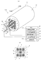
- (A) is the typical perspective view which looked at the sensor part from the exhaust downstream side
- (b) is the typical top view which looked at a part of the sensor part from the exhaust downstream side.
- it is a graph which shows an example of the temperature characteristic of the electrostatic capacitance Cp.
- It is a schematic block diagram which shows an example of the exhaust system of the diesel engine to which the sensor which concerns on one modification of this invention was applied.
- FIG. 1 is a schematic configuration diagram showing an example of an exhaust system of a diesel engine to which a sensor according to this embodiment is applied.
- a diesel engine (hereinafter simply referred to as an engine) 10 that is an internal combustion engine is provided with an intake manifold 10a and an exhaust manifold 10b.
- An intake passage 11 for introducing fresh air is connected to the intake manifold 10a, and an exhaust passage 12 for releasing exhaust gas to the atmosphere is connected to the exhaust manifold 10b.
- the exhaust passage 12 is provided with an exhaust pipe injection device 13 and an exhaust aftertreatment device 14 in order from the exhaust upstream side.
- the exhaust pipe injection device 13 injects unburned fuel (HC) into the exhaust passage 12 in accordance with an instruction signal output from an electronic control unit (hereinafter, ECU) 20.
- ECU electronice control unit
- the ECU 20 performs various controls such as fuel injection of the engine 10 and the exhaust pipe injection device 13, and includes a known CPU, ROM, RAM, input port, output port, and the like.
- the exhaust aftertreatment device 14 is configured by arranging an oxidation catalyst 15 and a DPF 16 in order from the exhaust upstream side in a case 14a.
- the oxidation catalyst 15 is formed by carrying a catalyst component on the surface of a ceramic carrier such as a cordierite honeycomb structure.
- a ceramic carrier such as a cordierite honeycomb structure.
- the DPF 16 constitutes the filter member of the present invention, and includes a cell that is disposed in the exhaust passage 12 and collects PM in the exhaust.
- the DPF 16 has a large number of cells that form a grid-like exhaust flow path partitioned by porous ceramic partition walls along the flow direction of the exhaust gas, and the upstream side and the downstream side of these cells are alternately plugged. It is configured to stop.
- a DPF inlet temperature sensor 31 is disposed upstream of the DPF 16, and a DPF outlet temperature sensor 32 is disposed downstream of the DPF 16.
- the DPF inlet temperature sensor 31 detects the temperature of the exhaust gas flowing into the DPF 16 (hereinafter referred to as DPF inlet temperature), and constitutes the temperature detection means 102 of the present invention.
- the DPF outlet temperature sensor 32 detects the temperature of exhaust gas flowing out from the DPF 16 (hereinafter referred to as DPF outlet temperature). These DPF inlet temperature and DPF outlet temperature are output to the electrically connected ECU 20.
- a plurality of cells 1 with the exhaust upstream side released (the exhaust downstream side plugged) are selected for capacitance measurement (hereinafter, the cell 1 is used for measurement).
- Cell a plurality of cells 1 with the exhaust upstream side released (the exhaust downstream side plugged) are selected for capacitance measurement (hereinafter, the cell 1 is used for measurement).
- the pair of cells 2 and 3 that face each other with the measurement cell 1 interposed therebetween are paired with a pair of electrodes A and B forming a capacitor.
- electrode cells are inserted (hereinafter, cells 2 and 3 are referred to as electrode cells).
- a pair of cells 4 and 5 that face each other with the measurement cell 1 interposed therebetween and into which the electrodes A and B are not inserted are provided with blocking members (not shown) that block the exhaust passages in the cells 4 and 5.
- cells 4 and 5 are referred to as blocking cells).
- the closing member provided in the closing cells 4 and 5 is made of ceramics made of the same material as the DPF 16, for example.
- the blocking member is embedded in the entire region in the blocking cells 4 and 5 so as to block all the exhaust passages from the plugging cells 4 and 5 to the non-plugged side. Note that the closing member does not necessarily have to be embedded in the entire area in the closing cells 4 and 5, and blocks a part of the flow path in the closing cells 4 and 5 (for example, the non-plugged side is closed). You may provide so that it may seal.
- the DPF 16 is configured so that the exhaust gas flowing into the measurement cell 1 flows into the electrode cells 2 and 3 without flowing into the blocking cells 4 and 5. Thereby, PM in the exhaust gas flowing into the measuring cell 1 is collected on the surface of the partition walls on the electrode cells 2 and 3 side, and the deposition on the partition walls on the closing cells 4 and 5 side is effectively suppressed.
- the electrodes A and B are, for example, conductive metal wires, and are inserted from the non-plugged side (exhaust downstream side) into the electrode cells 2 and 3 plugged on the exhaust upstream side to form a capacitor. .
- the electrodes A inserted into the electrode cell 2 project the base end portion on the exhaust downstream side outward, and the base end portions are connected to each other by a connection line 41 formed of a conductive metal member.
- the electrodes B inserted in the electrode cell 3 project the base end portion on the exhaust downstream side outward, and the base end portions are connected to each other by a connection line 42 formed of a conductive metal member.
- the protruding amount of the electrode A from the DPF 16 is set longer than the protruding amount of the electrode B in order to avoid contact between the connecting line A1 and the connecting line B1.
- these protrusion amounts do not necessarily need to make the electrode A longer, and the electrode B can be set longer.
- the DPF 16 that is a filter member provided with a pair of electrodes A and B is referred to as a sensor unit 8.
- the sensor 100 includes the sensor unit 8 described above, and an estimation unit 101 that estimates a PM deposition amount (PM deposition amount) collected in the DPF 16 based on the capacitance between the electrodes A and B. , And a capacitance type sensor.
- the estimation unit 101 includes a capacitance calculation unit 21 and a PM accumulation amount estimation unit 22.
- the capacitance calculation unit 21 and the PM accumulation amount estimation unit 22 are mounted on the ECU 20.
- the capacitance calculating unit 21 and the PM accumulation amount estimating unit 22 may be mounted on a hardware unit other than the ECU 20.
- the electrostatic capacity calculation unit 21 calculates the electrostatic capacity Cp between the electrodes A and B.
- the capacitance calculating unit 21 applies a DC voltage between the electrodes A and B to measure a resistance value Rp (an internal resistance value of the capacitor) between the electrodes A and B, and also applies an AC voltage between the electrodes A and B.
- Rp an internal resistance value of the capacitor
- the PM accumulation amount estimation unit 22 estimates the PM accumulation amount collected in the DPF 16 based on the capacitance Cp calculated by the capacitance calculation unit 21. For the estimation of the PM deposition amount, an approximate expression, a map, or the like obtained in advance by experiments can be used. Details of the estimation of the PM accumulation amount in the PM accumulation amount estimation unit 22 will be described later.
- the sensor 100 further includes temperature detection means 102 for detecting the temperature of the sensor unit 8 and a reference capacitance map 23.
- the temperature detection means 102 includes the DPF inlet temperature sensor 31 described above, a DPF inlet temperature sensor 31 as a temperature sensor provided in the vicinity of the DPF 16, and detection values of the DPF inlet temperature sensor 31 (here, DPF And a temperature estimation unit 25 that estimates the temperature of the sensor unit 8 based on the inlet temperature. That is, in the present embodiment, the temperature detection unit 102 is configured to estimate the temperature of the sensor unit 8 from the DPF inlet temperature. Note that the specific configuration of the temperature detection unit 102 is not limited to this, and for example, a thermocouple may be provided inside the DPF 16 to directly measure the temperature of the sensor unit 8. .
- the reference capacitance map 23 is created in advance by obtaining a reference capacitance that is a capacitance Cp between the electrodes A and B when PM is not collected in the DPF 16 for each temperature of the sensor unit 8. It represents the relationship between the temperature of the sensor unit 8 and the capacitance Cp between the electrodes A and B when PM is not collected.
- the reference capacitance map 23 may be obtained in advance by experiments or the like.
- the temperature estimation unit 25 and the reference capacitance map 23 are mounted on the ECU 20.
- the temperature estimation unit 25 and the reference capacitance map 23 may be mounted on a hardware unit other than the ECU 20.
- the PM accumulation amount estimation unit 22 constituting the estimation unit 101 refers to the reference capacitance map 23, and the reference electrostatic capacity corresponding to the temperature of the sensor unit 8 detected by the temperature detection unit 102.
- the capacitance is obtained, and the PM deposition amount is estimated based on the difference ⁇ Cp between the capacitances obtained by subtracting the reference capacitance from the capacitance Cp between the electrodes A and B obtained by the capacitance calculation unit 21. Configured.
- the capacitance Cp between the electrodes A and B increases as the temperature of the sensor unit 8 increases, and increases as the PM deposition amount increases.
- the capacitance Cp when the DPF 16 is submerged, the capacitance Cp also changes due to moisture in the DPF 16. As described above, the capacitance Cp is calculated based on the measured resistance value Rp and the impedance Z, but the resistance value Rp between the electrodes A and B greatly changes due to the influence of moisture in the DPF 16, and as a result. It is considered that the capacitance Cp cannot be obtained accurately.
- the apparatus further includes a moisture effect correction unit 24 that corrects the capacitance Cp between the electrodes A and B in accordance with the resistance value Rp between the electrodes A and B, and between the corrected electrodes A and B.
- the PM deposition amount estimation unit 22 is configured to estimate the PM deposition amount using the capacitance Cp.
- the moisture effect correction unit 24 uses, for example, the relationship between the resistance value Rp and the correction coefficient obtained in advance, obtains a correction coefficient corresponding to the measured resistance value Rp from the relationship, and calculates the correction coefficient as the capacitance Cp.
- the capacitance Cp is corrected by multiplying by the measured value.
- the moisture effect correction unit 24 is mounted on the ECU 20.
- the moisture effect correction unit 24 may be mounted on a hardware unit other than the ECU 20.
- the temperature detection unit 102 that detects the temperature of the sensor unit 8 and a pair when PM is not collected in the DPF 16 for each temperature of the sensor unit 8 in advance.
- a reference capacitance map 23 created by obtaining a reference capacitance Cp between the electrodes A and B, and the estimation means 101 (PM deposition amount estimation unit 22) includes a reference capacitance. Referring to the capacitance map 23, a reference capacitance corresponding to the temperature of the sensor unit 8 detected by the temperature detecting means 102 is obtained, and the static capacitance obtained by subtracting the reference capacitance from the capacitance Cp between the electrodes A and B is obtained. The PM deposition amount is estimated based on the difference ⁇ Cp in the electric capacity.
- the apparatus further includes a moisture effect correction unit 24 that corrects the capacitance Cp between the electrodes A and B according to the resistance value Rp between the electrodes A and B, and includes an estimation unit 101 (PM deposition amount estimation unit). 22) is configured to estimate the PM deposition amount using the corrected capacitance Cp between the electrodes A and B.
- a moisture effect correction unit 24 that corrects the capacitance Cp between the electrodes A and B according to the resistance value Rp between the electrodes A and B
- an estimation unit 101 PM deposition amount estimation unit 22
- This configuration makes it possible to estimate the PM deposition amount more accurately without being affected by moisture in the DPF 16.
- the estimation means 101 may be configured so that the influence due to the temperature characteristic of PM can also be compensated.
- a correction coefficient map referred to by the measured capacitance difference ⁇ Cp and the temperature of the sensor unit 8 is provided, and the correction coefficient obtained by the correction coefficient map is multiplied by the capacitance difference ⁇ Cp, whereby PM Compensating for the effect of temperature characteristics is conceivable.
- the DPF 16 is described as being disposed in the exhaust passage 12 with the non-plugged side of the measurement cell 1 facing the upstream side of the exhaust. May be arranged toward the exhaust upstream side. Further, the closing members of the closing cells 4 and 5 may be omitted.
- a bypass passage 18 branched from the exhaust passage 12 downstream of the oxidation catalyst 15 is provided, and a measurement DPF 16 having a reduced capacity is disposed in the bypass passage 18. Also good.
- a large-capacity DPF 17 (second filter member) may be provided in the exhaust passage 12 downstream of the branch portion.
Abstract
A sensor which can accurately calculate the accumulated PM amount is provided. The sensor is provided with a sensor unit 8 which comprises at least one pair of electrodes A, B in a filter member 16 which are arranged opposite of each another with a cell sandwiched therebetween and which form a capacitor, an estimation means 101 which estimates the accumulated amount of particulate matter captured by the filter member 16 on the basis of the capacitance between the electrodes A, B, a temperature detection means 102 which detects the temperature of the sensor unit 8, and a reference capacitance map 23 which is created by calculating a reference capacitance in advance for each temperature of the sensor unit 8, the reference capacitance being the capacitance between the electrodes A, B when no particulate matter has been captured in the filter member 16. The estimation means 101 refers to the reference capacitance map 23 to calculate the reference capacitance corresponding to the temperature of the sensor unit 8 detected by the temperature detection means 102, and estimates the accumulated amount of particulate matter on the basis of the capacitance difference found by subtracting said reference capacitance from the capacitance between electrodes A, B.
Description
本発明は、センサに関し、特に、排気中に含まれる粒子状物質(以下、PMという)を検出するPMセンサに関するものである。
The present invention relates to a sensor, and more particularly to a PM sensor that detects particulate matter (hereinafter referred to as PM) contained in exhaust gas.
ディーゼルエンジンから排出される排気ガス中のPMを捕集するフィルタとして、例えば、ディーゼルパティキュレートフィルタ(Diesel Particulate Filter、以下、DPF)が知られている。一般的に、DPFは、多孔質セラミックスの隔壁で区画された格子状の排気流路を形成する多数のセルを備え、これらセルの上流側と下流側とを交互に目封止して形成される。
As a filter for collecting PM in exhaust gas discharged from a diesel engine, for example, a diesel particulate filter (hereinafter referred to as DPF) is known. In general, a DPF includes a large number of cells that form a lattice-shaped exhaust passage partitioned by porous ceramic partition walls, and is formed by alternately plugging the upstream side and the downstream side of these cells. The
DPFのPM捕集量には限度があるため、PM堆積量が所定量に達すると、これら堆積したPMを燃焼除去するいわゆる強制再生が必要になる。そのため、強制再生の制御には、PM堆積量を精度良く測定することが望まれる。
Since there is a limit to the amount of PM collected by the DPF, when the amount of accumulated PM reaches a predetermined amount, so-called forced regeneration is required to burn and remove the accumulated PM. Therefore, it is desired to measure the PM accumulation amount with high accuracy for the forced regeneration control.
例えば、特許文献1には、排気下流側が目封止された測定用セルを挟んで対向する一対のセルに一対の電極をそれぞれ挿入し、これら電極間で形成されるコンデンサの静電容量に基づいてPM堆積量を検出するPMセンサが開示されている。
For example, in Patent Document 1, a pair of electrodes are inserted into a pair of cells facing each other with a measurement cell whose downstream side is plugged, and the capacitance of the capacitor formed between these electrodes is based on the capacitance of the capacitor. A PM sensor for detecting the amount of accumulated PM is disclosed.
しかしながら、上述の従来のPMセンサでは、静電容量の検出値が温度に依存し変化するため、PM堆積量を正確に求めることができないという問題があった。
However, the conventional PM sensor described above has a problem in that the amount of deposited PM cannot be accurately obtained because the detected capacitance value changes depending on the temperature.
そこで、本発明の目的は、上記課題を解決し、PM堆積量を正確に求めることが可能なセンサを提供することにある。
Therefore, an object of the present invention is to provide a sensor that can solve the above-described problems and can accurately determine the PM deposition amount.
本発明は上記目的を達成するために創案されたものであり、内燃機関の排気通路に配置されて排気中の粒子状物質を捕集するセルを含むフィルタ部材に、前記セルを挟んで対向配置されてコンデンサを形成する少なくとも一対の電極を設けたセンサ部と、前記電極間の静電容量に基づいて前記フィルタ部材に捕集される粒子状物質の堆積量を推定する推定手段と、を備えた静電容量式のセンサからなり、前記センサ部の温度を検出する温度検出手段と、予め前記センサ部の温度毎に、前記フィルタ部材に粒子状物質が捕集されていないときの前記一対の電極間の静電容量である基準静電容量を求めて作成された基準静電容量マップと、を備え、前記推定手段は、前記基準静電容量マップを参照して、前記温度検出手段で検出した前記センサ部の温度に対応する基準静電容量を求め、当該基準静電容量を前記電極間の静電容量から減じた静電容量の差分を基に、粒子状物質の堆積量を推定するように構成されるセンサである。
The present invention has been devised to achieve the above object, and is disposed opposite to a filter member including a cell that is disposed in an exhaust passage of an internal combustion engine and collects particulate matter in exhaust gas, with the cell interposed therebetween. And a sensor unit provided with at least a pair of electrodes forming a capacitor, and an estimation means for estimating the amount of particulate matter deposited on the filter member based on the capacitance between the electrodes. Temperature detection means for detecting the temperature of the sensor unit, and the pair of the particulate matter when the particulate matter is not collected in the filter member in advance for each temperature of the sensor unit. A reference capacitance map created by obtaining a reference capacitance which is a capacitance between the electrodes, and the estimation means refers to the reference capacitance map and is detected by the temperature detection means. The sensor A reference capacitance corresponding to the temperature of the electrode is obtained, and the amount of particulate matter deposited is estimated based on a difference in capacitance obtained by subtracting the reference capacitance from the capacitance between the electrodes. Sensor.
以下、添付図面に基づいて、本発明の実施形態に係る診断装置を説明する。同一の部品には同一の符号を付してあり、それらの名称及び機能も同じである。したがって、それらについての詳細な説明は繰返さない。
Hereinafter, a diagnostic apparatus according to an embodiment of the present invention will be described with reference to the accompanying drawings. The same parts are denoted by the same reference numerals, and their names and functions are also the same. Therefore, detailed description thereof will not be repeated.
図1は、本実施形態に係るセンサが適用されたディーゼルエンジンの排気系の一例を示す概略構成図である。
FIG. 1 is a schematic configuration diagram showing an example of an exhaust system of a diesel engine to which a sensor according to this embodiment is applied.
図1に示すように、内燃機関であるディーゼルエンジン(以下、単にエンジン)10には、吸気マニホールド10aと排気マニホールド10bとが設けられている。吸気マニホールド10aには新気を導入する吸気通路11が接続され、排気マニホールド10bには排気ガスを大気に放出する排気通路12が接続されている。
As shown in FIG. 1, a diesel engine (hereinafter simply referred to as an engine) 10 that is an internal combustion engine is provided with an intake manifold 10a and an exhaust manifold 10b. An intake passage 11 for introducing fresh air is connected to the intake manifold 10a, and an exhaust passage 12 for releasing exhaust gas to the atmosphere is connected to the exhaust manifold 10b.
排気通路12には、排気上流側から順に、排気管内噴射装置13、排気後処理装置14が設けられている。
The exhaust passage 12 is provided with an exhaust pipe injection device 13 and an exhaust aftertreatment device 14 in order from the exhaust upstream side.
排気管内噴射装置13は、電子制御ユニット(以下、ECU)20から出力される指示信号に応じて、排気通路12内に未燃燃料(HC)を噴射する。なお、エンジン10の多段噴射によるポスト噴射を用いる場合は、この排気管内噴射装置13を省略してもよい。なお、ECU20は、エンジン10や排気管内噴射装置13の燃料噴射等の各種制御を行うものであり、公知のCPUやROM、RAM、入力ポート、出力ポート等を備え構成されている。
The exhaust pipe injection device 13 injects unburned fuel (HC) into the exhaust passage 12 in accordance with an instruction signal output from an electronic control unit (hereinafter, ECU) 20. In addition, when using the post injection by the multistage injection of the engine 10, this in-pipe injection device 13 may be omitted. The ECU 20 performs various controls such as fuel injection of the engine 10 and the exhaust pipe injection device 13, and includes a known CPU, ROM, RAM, input port, output port, and the like.
排気後処理装置14は、ケース14a内に排気上流側から順に酸化触媒15、DPF16を配置して構成されている。
The exhaust aftertreatment device 14 is configured by arranging an oxidation catalyst 15 and a DPF 16 in order from the exhaust upstream side in a case 14a.
酸化触媒15は、例えば、コーディエライトハニカム構造体等のセラミックス製担体表面に触媒成分を担持して形成されている。酸化触媒15は、DPF16の強制再生時に、排気管内噴射装置13又はポスト噴射によって未燃燃料(HC)が供給されると、これを酸化して排気ガスの温度を上昇させる。これにより、DPF16はPM燃焼温度(例えば、約600℃)まで昇温されて、堆積したPMが燃焼除去される。
The oxidation catalyst 15 is formed by carrying a catalyst component on the surface of a ceramic carrier such as a cordierite honeycomb structure. When the unburnt fuel (HC) is supplied by the in-pipe injection device 13 or post-injection during forced regeneration of the DPF 16, the oxidation catalyst 15 oxidizes this and raises the temperature of the exhaust gas. As a result, the DPF 16 is heated to the PM combustion temperature (for example, about 600 ° C.), and the deposited PM is burned and removed.
DPF16は、本発明のフィルタ部材を構成するものであり、排気通路12に配置されて排気中のPMを捕集するセルを含む。DPF16は、多孔質セラミックスの隔壁で区画された格子状の排気流路を形成する多数のセルを排気ガスの流れ方向に沿って配置し、これらセルの上流側と下流側とを交互に目封止して構成されている。
The DPF 16 constitutes the filter member of the present invention, and includes a cell that is disposed in the exhaust passage 12 and collects PM in the exhaust. The DPF 16 has a large number of cells that form a grid-like exhaust flow path partitioned by porous ceramic partition walls along the flow direction of the exhaust gas, and the upstream side and the downstream side of these cells are alternately plugged. It is configured to stop.
DPF16の近傍の上流側には、DPF入口温度センサ31が配置され、DPF16の近傍の下流側には、DPF出口温度センサ32が配置されている。DPF入口温度センサ31は、DPF16に流入する排気ガスの温度(以下、DPF入口温度)を検出するものであり、本発明の温度検出手段102を構成するものである。DPF出口温度センサ32は、DPF16から流出する排気ガスの温度(以下、DPF出口温度)を検出するものである。これらDPF入口温度及びDPF出口温度は、電気的に接続されたECU20に出力される。
A DPF inlet temperature sensor 31 is disposed upstream of the DPF 16, and a DPF outlet temperature sensor 32 is disposed downstream of the DPF 16. The DPF inlet temperature sensor 31 detects the temperature of the exhaust gas flowing into the DPF 16 (hereinafter referred to as DPF inlet temperature), and constitutes the temperature detection means 102 of the present invention. The DPF outlet temperature sensor 32 detects the temperature of exhaust gas flowing out from the DPF 16 (hereinafter referred to as DPF outlet temperature). These DPF inlet temperature and DPF outlet temperature are output to the electrically connected ECU 20.
図2に示すように、DPF16には、排気上流側が解放(排気下流側が目封止)された複数のセル1が、静電容量の測定用として選定されている(以下、セル1を測定用セルという)。
As shown in FIG. 2, in the DPF 16, a plurality of cells 1 with the exhaust upstream side released (the exhaust downstream side plugged) are selected for capacitance measurement (hereinafter, the cell 1 is used for measurement). Cell).
また、測定用セル1に隔壁を介して隣接する4つのセル2~5のうち、測定用セル1を挟んで対向する一対のセル2,3には、コンデンサを形成する一対の電極A,Bがそれぞれ挿入されている(以下、セル2,3を電極用セルという)。
Of the four cells 2 to 5 adjacent to the measurement cell 1 through a partition wall, the pair of cells 2 and 3 that face each other with the measurement cell 1 interposed therebetween are paired with a pair of electrodes A and B forming a capacitor. Are inserted (hereinafter, cells 2 and 3 are referred to as electrode cells).
さらに、測定用セル1を挟んで対向し、且つ電極A,Bが挿入されない一対のセル4,5には、セル4,5内の排気流路を閉塞する閉塞部材(図示せず)が設けられている(以下、セル4,5を閉塞用セルという)。
Further, a pair of cells 4 and 5 that face each other with the measurement cell 1 interposed therebetween and into which the electrodes A and B are not inserted are provided with blocking members (not shown) that block the exhaust passages in the cells 4 and 5. (Hereinafter, cells 4 and 5 are referred to as blocking cells).
閉塞用セル4,5内に設けられる閉塞部材は、例えばDPF16と同一材料のセラミックスで形成されている。閉塞部材は、閉塞用セル4,5の目封止側から非目封止側に至る排気流路を全て塞ぐように、閉塞用セル4,5内の全領域に埋設されている。なお、閉塞部材は必ずしも、閉塞用セル4,5内の全領域に埋設される必要はなく、閉塞用セル4,5内の流路の一部を閉塞(例えば、非目封止側を目封止)するように設けてもよい。
The closing member provided in the closing cells 4 and 5 is made of ceramics made of the same material as the DPF 16, for example. The blocking member is embedded in the entire region in the blocking cells 4 and 5 so as to block all the exhaust passages from the plugging cells 4 and 5 to the non-plugged side. Note that the closing member does not necessarily have to be embedded in the entire area in the closing cells 4 and 5, and blocks a part of the flow path in the closing cells 4 and 5 (for example, the non-plugged side is closed). You may provide so that it may seal.
このように、DPF16では、測定用セル1に流入した排気ガスは、閉塞用セル4,5に流れ込むことなく、電極用セル2,3へと流れ込むように構成されている。これにより、測定用セル1に流入した排気ガス中のPMは、電極用セル2,3側の隔壁表面に捕集され、閉塞用セル4,5側の隔壁への堆積が効果的に抑制される。
Thus, the DPF 16 is configured so that the exhaust gas flowing into the measurement cell 1 flows into the electrode cells 2 and 3 without flowing into the blocking cells 4 and 5. Thereby, PM in the exhaust gas flowing into the measuring cell 1 is collected on the surface of the partition walls on the electrode cells 2 and 3 side, and the deposition on the partition walls on the closing cells 4 and 5 side is effectively suppressed. The
電極A,Bは、例えば導電性の金属線であって、排気上流側を目封止された電極用セル2,3に非目封止側(排気下流側)から挿入されてコンデンサを形成する。電極用セル2に挿入された電極Aは、排気下流側の基端部を外方に突出させると共に、その基端部を導電性の金属部材で形成された接続線41によって互いに接続されている。同様に、電極用セル3に挿入された電極Bは、排気下流側の基端部を外方に突出させると共に、その基端部を導電性の金属部材で形成された接続線42によって互いに接続されている。
The electrodes A and B are, for example, conductive metal wires, and are inserted from the non-plugged side (exhaust downstream side) into the electrode cells 2 and 3 plugged on the exhaust upstream side to form a capacitor. . The electrodes A inserted into the electrode cell 2 project the base end portion on the exhaust downstream side outward, and the base end portions are connected to each other by a connection line 41 formed of a conductive metal member. . Similarly, the electrodes B inserted in the electrode cell 3 project the base end portion on the exhaust downstream side outward, and the base end portions are connected to each other by a connection line 42 formed of a conductive metal member. Has been.
本実施形態において、DPF16からの電極Aの突出量は、接続線A1と接続線B1との接触を回避するために、電極Bの突出量よりも長く設定されている。なお、これら突出量は、必ずしも電極Aを長くする必要はなく、電極Bを長く設定することもできる。以下、フィルタ部材であるDPF16に、一対の電極A,Bを設けたものをセンサ部8と呼称する。
In this embodiment, the protruding amount of the electrode A from the DPF 16 is set longer than the protruding amount of the electrode B in order to avoid contact between the connecting line A1 and the connecting line B1. In addition, these protrusion amounts do not necessarily need to make the electrode A longer, and the electrode B can be set longer. Hereinafter, the DPF 16 that is a filter member provided with a pair of electrodes A and B is referred to as a sensor unit 8.
次に、本実施形態に係るセンサ100について説明する。
Next, the sensor 100 according to this embodiment will be described.
本実施形態に係るセンサ100は、上述のセンサ部8と、電極A,B間の静電容量に基づいてDPF16に捕集されるPMの堆積量(PM堆積量)を推定する推定手段101と、を備えた静電容量式のセンサからなる。
The sensor 100 according to the present embodiment includes the sensor unit 8 described above, and an estimation unit 101 that estimates a PM deposition amount (PM deposition amount) collected in the DPF 16 based on the capacitance between the electrodes A and B. , And a capacitance type sensor.
推定手段101は、静電容量演算部21と、PM堆積量推定部22と、を備えている。静電容量演算部21とPM堆積量推定部22は、ECU20に搭載されている。なお、静電容量演算部21とPM堆積量推定部22は、ECU20以外のハードウェアユニットに搭載されていてもよい。
The estimation unit 101 includes a capacitance calculation unit 21 and a PM accumulation amount estimation unit 22. The capacitance calculation unit 21 and the PM accumulation amount estimation unit 22 are mounted on the ECU 20. The capacitance calculating unit 21 and the PM accumulation amount estimating unit 22 may be mounted on a hardware unit other than the ECU 20.
静電容量演算部21は、電極A,B間の静電容量Cpを演算するものである。静電容量演算部21は、電極A,B間に直流電圧を印加して電極A,B間の抵抗値Rp(コンデンサの内部抵抗値)を測定すると共に、電極A,B間に交流電圧を印加して電極A,B間のインピーダンスZを測定し、以下の数式1により静電容量Cpを演算する。
The electrostatic capacity calculation unit 21 calculates the electrostatic capacity Cp between the electrodes A and B. The capacitance calculating unit 21 applies a DC voltage between the electrodes A and B to measure a resistance value Rp (an internal resistance value of the capacitor) between the electrodes A and B, and also applies an AC voltage between the electrodes A and B. Applied, the impedance Z between the electrodes A and B is measured, and the capacitance Cp is calculated by the following formula 1.

PM堆積量推定部22は、静電容量演算部21で演算される静電容量Cpに基づいて、DPF16に捕集されたPM堆積量を推定する。PM堆積量の推定には、予め実験により求めた近似式やマップ等を用いることができる。PM堆積量推定部22におけるPM堆積量の推定の詳細については、後述する。
The PM accumulation amount estimation unit 22 estimates the PM accumulation amount collected in the DPF 16 based on the capacitance Cp calculated by the capacitance calculation unit 21. For the estimation of the PM deposition amount, an approximate expression, a map, or the like obtained in advance by experiments can be used. Details of the estimation of the PM accumulation amount in the PM accumulation amount estimation unit 22 will be described later.
さて、本実施形態に係るセンサ100は、センサ部8の温度を検出する温度検出手段102と、基準静電容量マップ23と、をさらに備えている。
Now, the sensor 100 according to the present embodiment further includes temperature detection means 102 for detecting the temperature of the sensor unit 8 and a reference capacitance map 23.
本実施形態では、温度検出手段102は、上述のDPF入口温度センサ31と、DPF16の近傍に設けられた温度センサとしてのDPF入口温度センサ31と、DPF入口温度センサ31の検出値(ここではDPF入口温度)を基に、センサ部8の温度を推定する温度推定部25と、を備えている。つまり、本実施形態では、DPF入口温度からセンサ部8の温度を推定するように温度検出手段102を構成している。なお、温度検出手段102の具体的な構成はこれに限定されるものではなく、例えば、DPF16内部に熱電対を設けるなどして、センサ部8の温度を直接測定するように構成してもよい。
In the present embodiment, the temperature detection means 102 includes the DPF inlet temperature sensor 31 described above, a DPF inlet temperature sensor 31 as a temperature sensor provided in the vicinity of the DPF 16, and detection values of the DPF inlet temperature sensor 31 (here, DPF And a temperature estimation unit 25 that estimates the temperature of the sensor unit 8 based on the inlet temperature. That is, in the present embodiment, the temperature detection unit 102 is configured to estimate the temperature of the sensor unit 8 from the DPF inlet temperature. Note that the specific configuration of the temperature detection unit 102 is not limited to this, and for example, a thermocouple may be provided inside the DPF 16 to directly measure the temperature of the sensor unit 8. .
基準静電容量マップ23は、予めセンサ部8の温度毎に、DPF16にPMが捕集されていないときの電極A,B間の静電容量Cpである基準静電容量を求めて作成されるものであり、センサ部8の温度とPM非捕集時の電極A,B間の静電容量Cpとの関係を表したものである。基準静電容量マップ23は、予め実験等により求めておけばよい。
The reference capacitance map 23 is created in advance by obtaining a reference capacitance that is a capacitance Cp between the electrodes A and B when PM is not collected in the DPF 16 for each temperature of the sensor unit 8. It represents the relationship between the temperature of the sensor unit 8 and the capacitance Cp between the electrodes A and B when PM is not collected. The reference capacitance map 23 may be obtained in advance by experiments or the like.
温度推定部25と基準静電容量マップ23は、ECU20に搭載されている。なお、温度推定部25と基準静電容量マップ23は、ECU20以外のハードウェアユニットに搭載されていてもよい。
The temperature estimation unit 25 and the reference capacitance map 23 are mounted on the ECU 20. The temperature estimation unit 25 and the reference capacitance map 23 may be mounted on a hardware unit other than the ECU 20.
さらに、本実施形態では、推定手段101を構成するPM堆積量推定部22は、基準静電容量マップ23を参照して、温度検出手段102で検出したセンサ部8の温度に対応する基準静電容量を求め、当該基準静電容量を、静電容量演算部21で求めた電極A,B間の静電容量Cpから減じた静電容量の差分ΔCpを基に、PM堆積量を推定するように構成される。
Further, in the present embodiment, the PM accumulation amount estimation unit 22 constituting the estimation unit 101 refers to the reference capacitance map 23, and the reference electrostatic capacity corresponding to the temperature of the sensor unit 8 detected by the temperature detection unit 102. The capacitance is obtained, and the PM deposition amount is estimated based on the difference ΔCp between the capacitances obtained by subtracting the reference capacitance from the capacitance Cp between the electrodes A and B obtained by the capacitance calculation unit 21. Configured.
図3に示すように、電極A,B間の静電容量Cpは、センサ部8の温度が高くなるほど大きくなり、また、PM堆積量が大きくなるほど大きくなる。本実施形態では、測定した静電容量Cpから、現在のセンサ部8の温度における基準静電容量(DPF16にPMが捕集されていないときの静電容量Cp)を減じた静電容量の差分ΔCpを基に、PM堆積量を推定している。これにより、温度によらず正確に静電容量Cpを求めることが可能になる。
As shown in FIG. 3, the capacitance Cp between the electrodes A and B increases as the temperature of the sensor unit 8 increases, and increases as the PM deposition amount increases. In the present embodiment, the difference in capacitance obtained by subtracting the reference capacitance (capacitance Cp when PM is not collected in the DPF 16) at the current temperature of the sensor unit 8 from the measured capacitance Cp. Based on ΔCp, the PM deposition amount is estimated. As a result, the capacitance Cp can be accurately obtained regardless of the temperature.
また、DPF16が被水した場合など、DPF16内の水分によっても静電容量Cpが変化する。上述のように、静電容量Cpは測定した抵抗値RpとインピーダンスZとを基に演算されるが、DPF16内の水分の影響により電極A,B間の抵抗値Rpが大きく変化し、その結果、静電容量Cpが正確に求められなくなると考えられる。
In addition, when the DPF 16 is submerged, the capacitance Cp also changes due to moisture in the DPF 16. As described above, the capacitance Cp is calculated based on the measured resistance value Rp and the impedance Z, but the resistance value Rp between the electrodes A and B greatly changes due to the influence of moisture in the DPF 16, and as a result. It is considered that the capacitance Cp cannot be obtained accurately.
そこで、本実施形態では、電極A,B間の抵抗値Rpに応じて電極A,B間の静電容量Cpを補正する水分影響補正部24をさらに備え、補正後の電極A,B間の静電容量Cpを用いてPM堆積量を推定するようにPM堆積量推定部22を構成した。
Therefore, in the present embodiment, the apparatus further includes a moisture effect correction unit 24 that corrects the capacitance Cp between the electrodes A and B in accordance with the resistance value Rp between the electrodes A and B, and between the corrected electrodes A and B. The PM deposition amount estimation unit 22 is configured to estimate the PM deposition amount using the capacitance Cp.
水分影響補正部24は、例えば、予め求めておいた抵抗値Rpと補正係数との関係を用い、当該関係より、測定した抵抗値Rpに対応する補正係数を求め、補正係数を静電容量Cpの測定値に掛け合わせることで、静電容量Cpの補正を行うように構成される。水分影響補正部24は、ECU20に搭載されている。なお、水分影響補正部24は、ECU20以外のハードウェアユニットに搭載されていてもよい。水分影響補正部24を備えることで、水分の影響を受けずにより正確にPM堆積量を求めることが可能になる。
The moisture effect correction unit 24 uses, for example, the relationship between the resistance value Rp and the correction coefficient obtained in advance, obtains a correction coefficient corresponding to the measured resistance value Rp from the relationship, and calculates the correction coefficient as the capacitance Cp. The capacitance Cp is corrected by multiplying by the measured value. The moisture effect correction unit 24 is mounted on the ECU 20. The moisture effect correction unit 24 may be mounted on a hardware unit other than the ECU 20. By providing the moisture effect correcting unit 24, it is possible to obtain the PM deposition amount more accurately without being affected by moisture.
以上説明したように、本実施形態に係るセンサ100では、センサ部8の温度を検出する温度検出手段102と、予めセンサ部8の温度毎に、DPF16にPMが捕集されていないときの一対の電極A,B間の静電容量Cpである基準静電容量を求めて作成された基準静電容量マップ23と、を備え、推定手段101(PM堆積量推定部22)は、基準静電容量マップ23を参照して、温度検出手段102で検出したセンサ部8の温度に対応する基準静電容量を求め、当該基準静電容量を電極A,B間の静電容量Cpから減じた静電容量の差分ΔCpを基に、PM堆積量を推定するように構成されている。
As described above, in the sensor 100 according to the present embodiment, the temperature detection unit 102 that detects the temperature of the sensor unit 8 and a pair when PM is not collected in the DPF 16 for each temperature of the sensor unit 8 in advance. A reference capacitance map 23 created by obtaining a reference capacitance Cp between the electrodes A and B, and the estimation means 101 (PM deposition amount estimation unit 22) includes a reference capacitance. Referring to the capacitance map 23, a reference capacitance corresponding to the temperature of the sensor unit 8 detected by the temperature detecting means 102 is obtained, and the static capacitance obtained by subtracting the reference capacitance from the capacitance Cp between the electrodes A and B is obtained. The PM deposition amount is estimated based on the difference ΔCp in the electric capacity.
このように構成することで、センサ部8の温度の影響を受けることなく、正確にPM堆積量を推定することが可能になる。
With this configuration, it is possible to accurately estimate the PM deposition amount without being affected by the temperature of the sensor unit 8.
また、本実施形態では、電極A,B間の抵抗値Rpに応じて電極A,B間の静電容量Cpを補正する水分影響補正部24をさらに備え、推定手段101(PM堆積量推定部22)は、補正後の電極A,B間の静電容量Cpを用いて、PM堆積量を推定するように構成されている。
In the present embodiment, the apparatus further includes a moisture effect correction unit 24 that corrects the capacitance Cp between the electrodes A and B according to the resistance value Rp between the electrodes A and B, and includes an estimation unit 101 (PM deposition amount estimation unit). 22) is configured to estimate the PM deposition amount using the corrected capacitance Cp between the electrodes A and B.
このように構成することで、DPF16内の水分の影響を受けることなく、より正確にPM堆積量を推定することが可能になる。
This configuration makes it possible to estimate the PM deposition amount more accurately without being affected by moisture in the DPF 16.
本発明は上記実施形態に限定されるものではなく、本発明の趣旨を逸脱しない範囲で種々の変更を加え得ることは勿論である。
The present invention is not limited to the above-described embodiment, and it is needless to say that various modifications can be made without departing from the spirit of the present invention.
例えば、上記実施形態では言及しなかったが、静電容量CpにはDPF16を構成する材質の温度特性のみならず、PM自体の温度特性も影響を与えると考えられる。そこで、PMの温度特性による影響も補償できるように推定手段101を構成してもよい。例えば、測定した静電容量の差分ΔCpとセンサ部8の温度とにより参照される補正係数マップを備え、補正係数マップで得た補正係数を静電容量の差ΔCpに掛け合わせることで、PMの温度特性による影響を補償することが考えられる。
For example, although not mentioned in the above embodiment, it is considered that not only the temperature characteristic of the material constituting the DPF 16 but also the temperature characteristic of the PM itself affects the capacitance Cp. Therefore, the estimation means 101 may be configured so that the influence due to the temperature characteristic of PM can also be compensated. For example, a correction coefficient map referred to by the measured capacitance difference ΔCp and the temperature of the sensor unit 8 is provided, and the correction coefficient obtained by the correction coefficient map is multiplied by the capacitance difference ΔCp, whereby PM Compensating for the effect of temperature characteristics is conceivable.
また、上記実施形態では、DPF16は、排気通路12内に測定用セル1の非目封止側を排気上流側に向けて配置されるものとして説明したが、測定用セル1の目封止側を排気上流側に向けて配置してもよい。また、閉塞用セル4,5の閉塞部材を省略して構成してもよい。
In the above embodiment, the DPF 16 is described as being disposed in the exhaust passage 12 with the non-plugged side of the measurement cell 1 facing the upstream side of the exhaust. May be arranged toward the exhaust upstream side. Further, the closing members of the closing cells 4 and 5 may be omitted.
また、図4に示すように、酸化触媒15よりも下流側の排気通路12から分岐するバイパス通路18を設け、このバイパス通路18内に容量を小さくした計測用のDPF16を配置して構成してもよい。この場合、分岐部よりも下流側の排気通路12には容量の大きいDPF17(第2のフィルタ部材)を設けるとよい。また、計測用のDPF16の強制再生を実行する場合は、電極A,Bに電圧を印加してヒータとして機能させてもよい。
Further, as shown in FIG. 4, a bypass passage 18 branched from the exhaust passage 12 downstream of the oxidation catalyst 15 is provided, and a measurement DPF 16 having a reduced capacity is disposed in the bypass passage 18. Also good. In this case, a large-capacity DPF 17 (second filter member) may be provided in the exhaust passage 12 downstream of the branch portion. When forced regeneration of the measurement DPF 16 is executed, a voltage may be applied to the electrodes A and B so as to function as a heater.
Claims (4)
- 内燃機関の排気通路に配置されて排気中の粒子状物質を捕集するセルを含むフィルタ部材に、前記セルを挟んで対向配置されてコンデンサを形成する少なくとも一対の電極を設けたセンサ部と、前記電極間の静電容量に基づいて前記フィルタ部材に捕集される粒子状物質の堆積量を推定する推定手段と、を備えた静電容量式のセンサからなり、
前記センサ部の温度を検出する温度検出手段と、
予め前記センサ部の温度毎に、前記フィルタ部材に粒子状物質が捕集されていないときの前記一対の電極間の静電容量である基準静電容量を求めて作成された基準静電容量マップと、を備え、
前記推定手段は、前記基準静電容量マップを参照して、前記温度検出手段で検出した前記センサ部の温度に対応する基準静電容量を求め、当該基準静電容量を前記電極間の静電容量から減じた静電容量の差分を基に、粒子状物質の堆積量を推定するように構成される
ことを特徴とするセンサ。 A sensor unit provided with at least a pair of electrodes that are arranged in an exhaust passage of the internal combustion engine and collect cells in the exhaust gas, and that are arranged opposite to each other with the cell interposed therebetween, to form a capacitor; An estimation means for estimating the amount of particulate matter deposited on the filter member based on the capacitance between the electrodes, and a capacitance type sensor comprising:
Temperature detecting means for detecting the temperature of the sensor unit;
A reference capacitance map created in advance by obtaining a reference capacitance that is a capacitance between the pair of electrodes when particulate matter is not collected in the filter member for each temperature of the sensor unit. And comprising
The estimation unit refers to the reference capacitance map, obtains a reference capacitance corresponding to the temperature of the sensor unit detected by the temperature detection unit, and calculates the reference capacitance between the electrodes. A sensor configured to estimate a deposition amount of particulate matter based on a difference in capacitance subtracted from a capacitance. - 前記電極間の抵抗値に応じて前記電極間の静電容量を補正する水分影響補正部をさらに備え、
前記推定手段は、補正後の前記電極間の静電容量を用いて、粒子状物質の堆積量を推定するように構成される
請求項1記載のセンサ。 A water effect correction unit that corrects the capacitance between the electrodes according to the resistance value between the electrodes;
The sensor according to claim 1, wherein the estimation unit is configured to estimate a deposition amount of the particulate matter using a corrected capacitance between the electrodes. - 前記フィルタ部材は、多孔質性の隔壁で区画された格子状の排気流路を形成する複数の前記セルの上流側と下流側とを交互に目封止されたディーゼルパティキュレートフィルタからなり、
前記一対の電極は、少なくとも一つの前記セルを測定用セルとし、当該測定用セルに隔壁を介して隣接する四つのセルのうち、対向する一対のセルに非目封止側からそれぞれ挿入される
請求項1または2記載のセンサ。 The filter member is composed of a diesel particulate filter in which the upstream side and the downstream side of the plurality of cells forming a grid-like exhaust flow path partitioned by a porous partition wall are alternately plugged.
The pair of electrodes are at least one of the cells as a measurement cell, and are inserted from a non-plugged side into a pair of opposing cells among four cells adjacent to the measurement cell via a partition. The sensor according to claim 1 or 2. - 前記温度検出手段は、前記ディーゼルパティキュレートフィルタの近傍に設けられた温度センサと、前記温度センサの検出値を基に、前記センサ部の温度を推定する温度推定部と、を備える
請求項3記載のセンサ。 The temperature detection unit includes a temperature sensor provided in the vicinity of the diesel particulate filter, and a temperature estimation unit that estimates the temperature of the sensor unit based on a detection value of the temperature sensor. Sensor.
Applications Claiming Priority (2)
| Application Number | Priority Date | Filing Date | Title |
|---|---|---|---|
| JP2015043621A JP6500506B2 (en) | 2015-03-05 | 2015-03-05 | Sensor |
| JP2015-043621 | 2015-03-05 |
Publications (1)
| Publication Number | Publication Date |
|---|---|
| WO2016140214A1 true WO2016140214A1 (en) | 2016-09-09 |
Family
ID=56846731
Family Applications (1)
| Application Number | Title | Priority Date | Filing Date |
|---|---|---|---|
| PCT/JP2016/056225 WO2016140214A1 (en) | 2015-03-05 | 2016-03-01 | Sensor |
Country Status (2)
| Country | Link |
|---|---|
| JP (1) | JP6500506B2 (en) |
| WO (1) | WO2016140214A1 (en) |
Citations (6)
| Publication number | Priority date | Publication date | Assignee | Title |
|---|---|---|---|---|
| JPS5669503A (en) * | 1979-11-12 | 1981-06-10 | Kishimoto Akira | Coated film thickness measuring method and apparatus |
| JP2010151554A (en) * | 2008-12-24 | 2010-07-08 | Honda Motor Co Ltd | Particulate substance detector |
| JP2012037370A (en) * | 2010-08-06 | 2012-02-23 | Denso Corp | Sensor controller and exhaust treatment system having the same |
| JP2012083210A (en) * | 2010-10-12 | 2012-04-26 | Denso Corp | Particulate substance detection sensor |
| JP2014159782A (en) * | 2013-02-20 | 2014-09-04 | Isuzu Motors Ltd | Apparatus for measuring particulate substance |
| JP2014178270A (en) * | 2013-03-15 | 2014-09-25 | Pacific Ind Co Ltd | Tire abrasion detection device |
-
2015
- 2015-03-05 JP JP2015043621A patent/JP6500506B2/en not_active Expired - Fee Related
-
2016
- 2016-03-01 WO PCT/JP2016/056225 patent/WO2016140214A1/en active Application Filing
Patent Citations (6)
| Publication number | Priority date | Publication date | Assignee | Title |
|---|---|---|---|---|
| JPS5669503A (en) * | 1979-11-12 | 1981-06-10 | Kishimoto Akira | Coated film thickness measuring method and apparatus |
| JP2010151554A (en) * | 2008-12-24 | 2010-07-08 | Honda Motor Co Ltd | Particulate substance detector |
| JP2012037370A (en) * | 2010-08-06 | 2012-02-23 | Denso Corp | Sensor controller and exhaust treatment system having the same |
| JP2012083210A (en) * | 2010-10-12 | 2012-04-26 | Denso Corp | Particulate substance detection sensor |
| JP2014159782A (en) * | 2013-02-20 | 2014-09-04 | Isuzu Motors Ltd | Apparatus for measuring particulate substance |
| JP2014178270A (en) * | 2013-03-15 | 2014-09-25 | Pacific Ind Co Ltd | Tire abrasion detection device |
Also Published As
| Publication number | Publication date |
|---|---|
| JP6500506B2 (en) | 2019-04-17 |
| JP2016161541A (en) | 2016-09-05 |
Similar Documents
| Publication | Publication Date | Title |
|---|---|---|
| JP6028615B2 (en) | Particulate matter measuring device | |
| JP6459437B2 (en) | Diagnostic device and sensor | |
| JP6089763B2 (en) | Particulate matter measuring device | |
| CN107076692B (en) | Sensor with a sensor element | |
| JP6136298B2 (en) | Exhaust gas purification device for internal combustion engine | |
| WO2016047529A1 (en) | Diagnostic device | |
| JP6036388B2 (en) | Particulate matter measuring device | |
| WO2016140215A1 (en) | Sensor | |
| WO2016024591A1 (en) | Sensor | |
| WO2015053323A1 (en) | Exhaust purification system | |
| JP6032053B2 (en) | Exhaust system state detection device and control device | |
| US10481061B2 (en) | Sensor for detecting an emission amount of particulate matter | |
| JP6056537B2 (en) | Particulate matter measuring apparatus and filter manufacturing method | |
| JP2015059476A (en) | Exhaust purification system of internal combustion engine | |
| JP6405938B2 (en) | Diagnostic device and sensor | |
| WO2015053322A1 (en) | Exhaust purification system | |
| WO2016140214A1 (en) | Sensor | |
| JP6201578B2 (en) | Diagnostic equipment | |
| JP6123343B2 (en) | Exhaust gas purification device for internal combustion engine | |
| JP6451179B2 (en) | Diagnostic equipment | |
| JP6417780B2 (en) | Sensor | |
| JP2015055167A (en) | Exhaust emission control device |
Legal Events
| Date | Code | Title | Description |
|---|---|---|---|
| 121 | Ep: the epo has been informed by wipo that ep was designated in this application |
Ref document number: 16758907 Country of ref document: EP Kind code of ref document: A1 |
|
| NENP | Non-entry into the national phase |
Ref country code: DE |
|
| 122 | Ep: pct application non-entry in european phase |
Ref document number: 16758907 Country of ref document: EP Kind code of ref document: A1 |