WO2016139952A1 - 抵抗スポット溶接装置 - Google Patents
抵抗スポット溶接装置 Download PDFInfo
- Publication number
- WO2016139952A1 WO2016139952A1 PCT/JP2016/001174 JP2016001174W WO2016139952A1 WO 2016139952 A1 WO2016139952 A1 WO 2016139952A1 JP 2016001174 W JP2016001174 W JP 2016001174W WO 2016139952 A1 WO2016139952 A1 WO 2016139952A1
- Authority
- WO
- WIPO (PCT)
- Prior art keywords
- energization
- applied pressure
- spot welding
- resistance spot
- electrodes
- Prior art date
Links
Images


Classifications
-
- B—PERFORMING OPERATIONS; TRANSPORTING
- B23—MACHINE TOOLS; METAL-WORKING NOT OTHERWISE PROVIDED FOR
- B23K—SOLDERING OR UNSOLDERING; WELDING; CLADDING OR PLATING BY SOLDERING OR WELDING; CUTTING BY APPLYING HEAT LOCALLY, e.g. FLAME CUTTING; WORKING BY LASER BEAM
- B23K11/00—Resistance welding; Severing by resistance heating
- B23K11/10—Spot welding; Stitch welding
- B23K11/11—Spot welding
- B23K11/115—Spot welding by means of two electrodes placed opposite one another on both sides of the welded parts
-
- B—PERFORMING OPERATIONS; TRANSPORTING
- B23—MACHINE TOOLS; METAL-WORKING NOT OTHERWISE PROVIDED FOR
- B23K—SOLDERING OR UNSOLDERING; WELDING; CLADDING OR PLATING BY SOLDERING OR WELDING; CUTTING BY APPLYING HEAT LOCALLY, e.g. FLAME CUTTING; WORKING BY LASER BEAM
- B23K11/00—Resistance welding; Severing by resistance heating
- B23K11/24—Electric supply or control circuits therefor
- B23K11/241—Electric supplies
-
- B—PERFORMING OPERATIONS; TRANSPORTING
- B23—MACHINE TOOLS; METAL-WORKING NOT OTHERWISE PROVIDED FOR
- B23K—SOLDERING OR UNSOLDERING; WELDING; CLADDING OR PLATING BY SOLDERING OR WELDING; CUTTING BY APPLYING HEAT LOCALLY, e.g. FLAME CUTTING; WORKING BY LASER BEAM
- B23K11/00—Resistance welding; Severing by resistance heating
- B23K11/16—Resistance welding; Severing by resistance heating taking account of the properties of the material to be welded
-
- B—PERFORMING OPERATIONS; TRANSPORTING
- B23—MACHINE TOOLS; METAL-WORKING NOT OTHERWISE PROVIDED FOR
- B23K—SOLDERING OR UNSOLDERING; WELDING; CLADDING OR PLATING BY SOLDERING OR WELDING; CUTTING BY APPLYING HEAT LOCALLY, e.g. FLAME CUTTING; WORKING BY LASER BEAM
- B23K11/00—Resistance welding; Severing by resistance heating
- B23K11/24—Electric supply or control circuits therefor
- B23K11/25—Monitoring devices
- B23K11/252—Monitoring devices using digital means
- B23K11/253—Monitoring devices using digital means the measured parameter being a displacement or a position
-
- B—PERFORMING OPERATIONS; TRANSPORTING
- B23—MACHINE TOOLS; METAL-WORKING NOT OTHERWISE PROVIDED FOR
- B23K—SOLDERING OR UNSOLDERING; WELDING; CLADDING OR PLATING BY SOLDERING OR WELDING; CUTTING BY APPLYING HEAT LOCALLY, e.g. FLAME CUTTING; WORKING BY LASER BEAM
- B23K11/00—Resistance welding; Severing by resistance heating
- B23K11/24—Electric supply or control circuits therefor
- B23K11/25—Monitoring devices
- B23K11/252—Monitoring devices using digital means
- B23K11/255—Monitoring devices using digital means the measured parameter being a force
-
- B—PERFORMING OPERATIONS; TRANSPORTING
- B23—MACHINE TOOLS; METAL-WORKING NOT OTHERWISE PROVIDED FOR
- B23K—SOLDERING OR UNSOLDERING; WELDING; CLADDING OR PLATING BY SOLDERING OR WELDING; CUTTING BY APPLYING HEAT LOCALLY, e.g. FLAME CUTTING; WORKING BY LASER BEAM
- B23K2101/00—Articles made by soldering, welding or cutting
- B23K2101/006—Vehicles
-
- B—PERFORMING OPERATIONS; TRANSPORTING
- B23—MACHINE TOOLS; METAL-WORKING NOT OTHERWISE PROVIDED FOR
- B23K—SOLDERING OR UNSOLDERING; WELDING; CLADDING OR PLATING BY SOLDERING OR WELDING; CUTTING BY APPLYING HEAT LOCALLY, e.g. FLAME CUTTING; WORKING BY LASER BEAM
- B23K2103/00—Materials to be soldered, welded or cut
- B23K2103/02—Iron or ferrous alloys
- B23K2103/04—Steel or steel alloys
- B23K2103/05—Stainless steel
Definitions
- the present invention relates to a resistance spot welding apparatus for performing resistance spot welding which is a kind of lap resistance welding method.
- resistance spot welding is performed by attaching a plate set 3 of two or more stacked steel plates (here, a set of two plates of a lower steel plate 1 and an upper steel plate 2) to a pair of upper and lower electrodes (lower The electrode 4 and the upper electrode 5) are sandwiched between the electrode 4 and the upper electrode 5) and energized while being pressed to melt the contact portion of the steel plates 1 and 2 to form a nugget 9 of a necessary size to obtain a welded joint.
- the quality of the joint obtained in this way depends on the size of the nugget diameter, or the shear tensile strength (strength when the tensile test is performed in the shear direction of the joint) and the cross tensile strength (tensile in the peeling direction of the joint). It is evaluated based on the strength of the test) and the fatigue strength. In particular, the amount of C in the steel sheet tends to increase with increasing strength. On the other hand, it is known that the cross tensile strength decreases in a high-strength steel sheet having a large amount of C.
- an increase in the nugget diameter can be considered from the viewpoint of the welding method.
- the nugget is conversely reduced, which causes a decrease in joint strength.
- the surface of the steel sheet for automobiles is subjected to galvanizing treatment mainly containing zinc for the purpose of rust prevention. It is known that when a steel sheet has such a galvanized layer, it becomes difficult to secure a large nugget because it tends to cause splatter when applying resistance spot welding to the automobile during automobile assembly. Yes.
- Patent Document 1 discloses a method for forming a nugget in a three-layer steel sheet. According to this method, after the first stage of welding, the second and subsequent stages of welding are energized / paused to form a pulsation, so that even in a three-layered plate assembly such as thin plates, thick plates, and thick plates It is said that a sufficient nugget diameter can be formed.
- Patent Document 3 states that a nugget of a certain size can be secured by limiting the time ratio between preliminary energization and nugget formation in a zinc-based plated steel sheet.
- Patent Document 4 it is assumed that a nugget of a certain size can be secured by repeating cooling and energization at a current value higher than the current value after performing preliminary energization in a zinc-based plated steel sheet. Yes.
- Japanese Patent No. 4728926 JP 2011-167742 A Japanese Patent No. 3894539 Japanese Patent No. 3922263
- Patent Documents 1 to 4 still have a problem that it is difficult to ensure a stable nugget diameter.
- a construction disturbance such as an unintended sheet gap, which affects nugget formation.
- the present invention solves the above-described problem, and suppresses the occurrence of scattering and forms a large nugget, thereby ensuring a stable nugget diameter even when there is a construction disturbance such as a plate gap.
- An object is to provide a spot welding apparatus.
- the inventors have repeatedly studied resistance spot welding of a plate assembly including a high-strength steel plate.
- the pressure applied between the electrodes during welding was measured in real time. That is, using a pressurizing mechanism that pressurizes the upper electrode, a load value (measured pressurization force or simply referred to as pressurization force) applied between the electrodes during welding was measured in real time using this pressurization mechanism.
- the pressure applied by the upper electrode can be set with a specified value (referred to as a specified pressure). As a result of the measurement, it was found that there was a difference between the specified pressure and the pressure applied between the electrodes during welding.
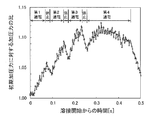
- FIG. 2 is a diagram showing changes in the applied pressure with respect to the initial applied pressure when resistance spot welding is performed by repeating energization and pause.
- FIG. 3 is a diagram illustrating a change in the applied pressure with respect to the initial applied pressure when resistance spot welding is performed by energizing with a constant current.
- pressurization was carried out for about 10 cycles (200 ms) before energization to obtain a stable state, and the average applied pressure during one energization start cycle (20 ms) was called the initial applied pressure.
- the nugget is abruptly formed at the initial stage of energization and expands, thereby increasing the measured pressure. Scattering is considered to occur when the pressure around the nugget is insufficient. That is, when the measured applied pressure during energization becomes a certain value or more, it is considered that the pressurization around the nugget is relatively lowered, which leads to the occurrence of scattering. On the other hand, when the increase in the applied pressure is small, it indicates that the thermal expansion due to the nugget formation is small, and as a result, the nugget diameter is not sufficient.
- the nugget is solidified and contracted, and the measured pressure is lowered.
- the heat is transferred to the surroundings by heat transfer, so that the temperature of the portion around the nugget is increased and softened, the pressure state by the electrode is secured, and the scattering is considered to be suppressed.
- the cooling progresses after a lapse of time from the energization stop, it becomes difficult to form a nugget in the next energization.
- the inventors examined whether a large nugget diameter could be formed without occurrence of scattering by utilizing the above phenomenon and controlling the applied pressure. As a result, they obtained knowledge that the nugget diameter can be finally increased while suppressing the occurrence of scattering by repeating energization and pause in the initial energization period and appropriately controlling the applied pressure therebetween.
- Based on the applied pressure F measured by the applied pressure measuring device, a control device for controlling energization between the electrodes is provided,
- the control device applies the pressurization force expressed by the formula (1) when the applied pressure F measured by the applied pressure measuring device is between 20 ms and 80 ms with respect to the initial applied force Fi.
- the resistance spot welding apparatus according to any one of [1] to [3], It further comprises a gun arm on which a pair of electrodes are installed,
- the pressure measuring device is a resistance spot welding device that is a strain gauge that measures the strain of the gun arm.
- a large nugget can be formed while suppressing the occurrence of scattering when performing resistance spot welding on a plate assembly in which two or more steel plates are overlapped.
- FIG. 1 is a diagram showing an outline of resistance spot welding.
- FIG. 2 is a diagram showing changes in the applied pressure with respect to the initial applied pressure when resistance spot welding is performed by repeating energization and pause.
- FIG. 3 is a diagram illustrating a change in the applied pressure with respect to the initial applied pressure when resistance spot welding is performed by energizing with a constant current.
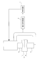
- FIG. 4 is a diagram showing a configuration of the resistance spot welding apparatus according to the embodiment of the present invention.
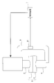
- FIG. 5 is a diagram illustrating a configuration of the resistance spot welding apparatus according to the embodiment of the present invention, and is a diagram illustrating an example in which the pressure measuring device is configured by a strain gauge.
- FIG. 4 is a diagram showing a configuration of the resistance spot welding apparatus according to the embodiment of the present invention.
- This apparatus is a resistance spot welding apparatus in which a plate set 3 in which two or more steel plates (1, 2) are overlapped is sandwiched between a pair of electrodes and energized and welded while being pressed.
- This apparatus includes a pair of electrodes (lower electrode 4 and upper electrode 5), a pressure measuring device 6, and a control device 7.
- the applied pressure measuring device 6 measures the applied pressure F by the electrodes 4 and 5 (hereinafter simply referred to as applied pressure F), and outputs the measured applied pressure F to the control device 7.
- the pressure measuring device 6 can be configured as a strain gauge 61 that measures the strain of the gun arm 8 on which the lower electrode 4 and the upper electrode 5 are installed as shown in FIG. At the time of pressurization, the gun arm 8 is distorted substantially in proportion to the applied pressure F. By measuring this strain amount with the strain gauge 61 and converting it to the applied pressure F, the applied pressure F can be measured.
- a load cell capable of measuring the pressurizing force F may be used, or the strain gauge 61 and the load cell may be used in combination.
- the control device 7 controls the applied pressure F as follows based on the applied pressure F measured by the applied pressure measuring device 6. Specifically, the control device 7 determines that the applied pressure F h after the start of energization is equal to the applied pressure F h shown in Expression (1) when the elapsed time from the start of energization is 20 ms to 80 ms with respect to the initial applied pressure Fi. When (1) is reached, the energization is stopped for 20 ms or more and 60 ms or less.
- the initial pressurizing force Fi used the average pressurizing force for one cycle (20 ms) after starting energization after applying pressure for about 10 cycles (200 ms) before energization. Since the applied pressure immediately after the start of energization is substantially equal to the applied pressure (designated applied pressure) set in the servo gun, the designated applied pressure may be the initial applied pressure Fi. Alternatively, an average pressure of 0 ms to 20 ms from the start of energization may be used as the initial pressure Fi.
- control device 7 controls the energization so that the energization of 20 ms to 80 ms and the pause of 20 ms to 60 ms are repeated once more.
- the control device 7 then applies the applied pressure F h ( shown in equation (3) to the applied pressure F c (N ⁇ 1) immediately after the (N ⁇ 1) th pause by applying the Nth power supply. N) , stop energization. 1.04 ⁇ F c (N ⁇ 1) ⁇ F h (N) ⁇ 1.15 ⁇ F c (N ⁇ 1) (3)
- F h (N) is smaller than 1.04 ⁇ F c (N ⁇ 1), the probability of scattering increases, and when it is higher than 1.15 ⁇ F c (N ⁇ 1) , nugget growth is inhibited.
- control device 7 controls energization so that energization is started again when the applied pressure F reaches the applied pressure F c (N) shown in Expression (4).
- N is a natural number of 2 or more.
- the last energization time is preferably 100 ms or more and 300 ms or less.
- the last energization means the (N + 1) th energization. If it is less than 100 ms, nugget formation is insufficient. Energization for a time exceeding 300 ms deteriorates workability and contributes little to nugget formation.
- the last energization time may be selected in accordance with the time required for the first energization and the subsequent energization and rest in the above range.
- a resistance spot welding apparatus includes a pair of upper and lower electrodes, a welding current that is pressurized and energized across a portion to be welded by the pair of electrodes, and that can arbitrarily control the welding current during welding. What is necessary is just to have a control apparatus.
- the pressurizing mechanism air cylinder, servo motor, etc.
- current control mechanism AC, DC, etc.
- type stationary, robot gun, etc.
- the present invention is preferably applied to a welding apparatus for a plurality of plates including a galvanized steel plate and a high-strength steel plate.
- Galvanized steel sheets and high-strength steel sheets are more likely to be scattered due to sheet gaps than ordinary steel sheets.
- the present invention since the present invention has an effect of suppressing the occurrence of scattering, it is more effective when applied to welding of a plate set including at least one such steel plate.
- the tensile strength of at least one steel plate is 980 MPa or more among the plate sets to be welded, the occurrence of scattering can be suppressed and a large nugget diameter can be formed.
- At least one steel plate has 0.15 ⁇ C ⁇ 0.30 (mass%), 1.9 ⁇ Mn ⁇ 5.0 (mass%), 0.2 ⁇ Si ⁇ 2. Even a high strength steel sheet having a 0.0 (mass%) component and a tensile strength of 980 MPa or more can suppress the occurrence of scattering and form a large nugget diameter.
- a galvanized steel plate shows the steel plate which has a plating layer which has zinc as a main component, and all the conventionally well-known zinc plating layers are included in the plating layer which has zinc as a main component.
- the plating layer containing zinc as a main component includes a hot dip galvanized layer, an electrogalvanized layer, an Al plated layer, a Zn—Al plated layer, a Zn—Ni layer, and the like.
- the resistance spot welding apparatus measures the applied pressure, and based on the measured applied pressure, performs energization and pause while appropriately controlling the applied pressure during energization. Generation can be suppressed, and a large nugget can be formed. For this reason, the nugget diameter can be stably secured even when there is a construction disturbance such as a sheet gap.
- a resistance spot welded joint was produced for a plate set 3 in which two alloyed hot-dip galvanized steel plates (lower steel plate 1 and upper steel plate 2) were stacked using the apparatus shown in FIG. .
- the apparatus used in the examples is a C gun type welding apparatus that pressurizes an electrode with a servo motor.
- a DC power source was used as the power source.
- DR-type electrodes of alumina-dispersed copper having a tip radius of curvature R of 40 mm and a tip diameter of 8 mm were used.
- a high-strength steel plate having a tensile strength of 980 MPa class with a thickness of 0.8 to 2.6 mm and a 1470 MPa class with a thickness of 2.0 mm was used. Two steel plates of the same type and thickness were stacked and welded.
- the applied pressure during energization was measured using a strain gauge 61 attached to the C gun.
- the energization was changed so that the measured applied pressure became a predetermined value.
- Table 1 shows the results of investigating the occurrence of scattering and the nugget diameter during welding.
- the nugget diameter was evaluated by the etching structure of the cut section.
- the nugget diameter was evaluated by assuming that the plate thickness was t (mm), and that ⁇ 5.5 ⁇ t was ⁇ , and less than 5.5 ⁇ t was ⁇ . That is, a nugget diameter of 5.5 ⁇ t or more was set as an appropriate diameter.
- I 1 (kA) is the current value of the first energization
- T 1 (ms) is the energization time of the first energization
- F h (1) / F i is the applied pressure F h ( The ratio of 1)
- Tc 1 (ms) is the first pause time
- F c (1) / F i is the ratio of the applied pressure F c (1) to the initial applied pressure Fi
- F c (1) / F h (1) Is the ratio of the applied pressure F c (1) at which energization is resumed to the applied pressure F h (1) at which energization is suspended.
- I 2 (kA) is the current value of the second energization
- T 2 (ms) is the energization time of the second energization.
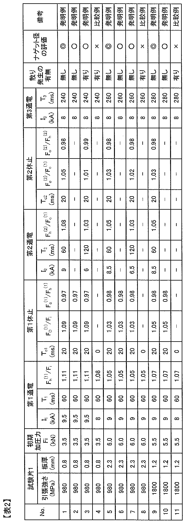
- resistance spot welding is performed using a resistance welding machine having a DC power supply with a servo motor pressurization type attached to a C gun, with respect to a plate assembly in which three alloyed hot-dip galvanized steel sheets are stacked. A resistance spot welded joint was prepared.
- DR-type electrodes of alumina-dispersed copper having a tip radius of curvature R of 40 mm and a tip diameter of 8 mm were used.
- a high-strength steel plate having a plate thickness of 0.8 to 2.3 mm of the 980 MPa class and a thickness of 1.2 mm of the 1800 MPa class was used. Three steel plates of the same type and thickness were stacked and welded.
- the applied pressure during energization was measured using a strain gauge attached to the C gun.
- the applied pressure was changed so that the measured applied pressure became a predetermined value.
- Table 2 shows the results of investigating the occurrence of scattering and the nugget diameter during welding.
- the nugget diameter was evaluated by the etching structure of the cut section.
- the nugget diameter was evaluated by assuming that the plate thickness was t (mm), and that ⁇ 5.5 ⁇ t was ⁇ , and less than 5.5 ⁇ t was ⁇ . That is, a nugget diameter of 5.5 ⁇ t or more was set as an appropriate diameter.
- I 1 (kA) is the current value of the first energization
- T 1 (ms) is the energization time of the first energization
- F h (1) / F i is the applied pressure F h ( The ratio of 1)
- Tc 1 (ms) is the first pause time
- F c (1) / F i is the ratio of the applied pressure F c (1) to the initial applied pressure Fi
- F c (1) / F h (1) Is the ratio of the applied pressure at which energization is resumed to the applied pressure at which energization is suspended.
- F h (2) / F c (1) is the ratio of the applied pressure during the energization stop after the second energization to the applied pressure immediately after the first stop
- F c (2) / F c (1) is The ratio of the pressing force immediately after the second pause to the pressing force immediately after the first pause
- F c (2) / F h (2) is the value immediately after the second pause with respect to the pressing force at the time of the energization pause after the second energization.
- I 2 (kA) and I 3 (kA) are the current values of the second and third energizations
- T 2 (ms) and T 3 (ms) are the energization times of the second and third energizations
- Tc 2 (ms) is the second pause time.
Abstract
Description
[1] 二枚以上の鋼板を重ね合せた板組を、一対の溶接電極で挟持し、加圧しながら通電して溶接する抵抗スポット溶接装置であって、
一対の電極と、
電極による加圧力Fを測定する加圧力計測装置と、
加圧力計測装置によって測定された加圧力Fに基づいて、電極間の通電を制御する制御装置を備え、
制御装置は、加圧力計測装置によって測定された通電開始後の加圧力Fが、初期加圧力Fiに対し、通電開始からの経過時間が20ms以上80ms以下の間で式(1)に示す加圧力Fh (1)となったら、20ms以上60ms以下の通電の休止を行い、
その後、加圧力Fが、式(2)に示す加圧力Fc (1)となったら、再度通電を開始するように通電を制御する抵抗スポット溶接装置。
1.03×Fi≦Fh (1)≦1.15×Fi (1)
1.01×Fi≦Fc (1)≦0.99×Fh (1) (2)
[2] [1]に記載の抵抗スポット溶接装置であって、
制御装置はさらに、
前記通電の休止後に、20ms以上80ms以下の通電と、20ms以上60ms以下の休止を1回以上繰り返し、
(N-1)回目の休止直後の加圧力Fc (N-1)に対して、加圧力FがN回目の通電により式(3)に示す加圧力Fh (N)となったら、通電を休止し、
その後、加圧力Fが、式(4)に示す加圧力Fc (N)に到達となったら、再度通電を開始するように通電を制御する抵抗スポット溶接装置。
1.04×Fc (N-1)≦Fh (N)≦1.15×Fc (N-1) (3)
Fc (N-1)≦Fc (N)≦0.99×Fh (N) (4)
N:2以上の自然数
[3] [1]または[2]に記載の抵抗スポット溶接装置であって、制御装置は、最後のN+1回目の通電時間は100ms以上300ms以下となるように通電を制御する抵抗スポット溶接装置。
[4] [1]から[3]のうちいずれかに記載の抵抗スポット溶接装置であって、
一対の電極が設置されたガンアームをさらに備え、
加圧力計測装置は、ガンアームのひずみを測定するひずみ計である抵抗スポット溶接装置。
1.03×Fi≦Fh (1)≦1.15×Fi (1)
Fh (1)が1.03×Fiより小さいとナゲット近傍の加圧が十分に得られず、散りの発生確率が高くなり、1.15×Fiより高いとナゲットの成長が阻害される。
1.01×Fi≦Fc (1)≦0.99×Fh (1) (2)
Fc (1)が1.01×Fiより低くなると冷却が進行するため次の加熱による効果が小さくなり、0.99×Fh (1)より高いとナゲットの温度が高く再通電時に散り発生の可能性が高まる。
1.04×Fc (N-1)≦Fh (N)≦1.15×Fc (N-1) (3)
Fh (N)が1.04×Fc (N-1)より小さいと散りの発生確率が高くなり、1.15×Fc (N-1)より高いとナゲットの成長が阻害される。
Fc (N-1)≦Fc (N)≦0.99×Fh (N) (4)
Fc (N)がFc (N-1)より低くなると冷却が進行するため次の加熱による効果が小さくなり、0.99×Fh (N)より高いと再通電時に散り発生の可能性が高まる。

2 上の鋼板
3 板組
4 下の電極
5 上の電極
6 加圧力計測装置
61 ひずみ計
7 制御装置
8 ガンアーム
9 ナゲット
Claims (4)
- 二枚以上の鋼板を重ね合せた板組を、一対の溶接電極で挟持し、加圧しながら通電して溶接する抵抗スポット溶接装置であって、
一対の電極と、
電極による加圧力Fを測定する加圧力計測装置と、
加圧力計測装置によって測定された加圧力Fに基づいて、電極間の通電を制御する制御装置を備え、
制御装置は、加圧力計測装置によって測定された通電開始後の加圧力Fが、初期加圧力Fiに対し、通電開始からの経過時間が20ms以上80ms以下の間で式(1)に示す加圧力Fh (1)となったら、20ms以上60ms以下の通電の休止を行い、
その後、加圧力Fが、式(2)に示す加圧力Fc (1)となったら、再度通電を開始するように通電を制御する抵抗スポット溶接装置。
1.03×Fi≦Fh (1)≦1.15×Fi (1)
1.01×Fi≦Fc (1)≦0.99×Fh (1) (2) - 請求項1に記載の抵抗スポット溶接装置であって、
制御装置はさらに、
前記通電の休止後に、20ms以上80ms以下の通電と、20ms以上60ms以下の休止を1回以上繰り返し、
(N-1)回目の休止直後の加圧力Fc (N-1)に対して、加圧力FがN回目の通電により式(3)に示す加圧力Fh (N)となったら、通電を休止し、
その後、加圧力Fが、式(4)に示す加圧力Fc (N)に到達となったら、再度通電を開始するように通電を制御する抵抗スポット溶接装置。
1.04×Fc (N-1)≦Fh (N)≦1.15×Fc (N-1) (3)
Fc (N-1)≦Fc (N)≦0.99×Fh (N) (4)
N:2以上の自然数 - 請求項1または2に記載の抵抗スポット溶接装置であって、制御装置は、最後のN+1回目の通電時間は100ms以上300ms以下となるように通電を制御する抵抗スポット溶接装置。
- 請求項1から3のうちいずれかに記載の抵抗スポット溶接装置であって、
一対の電極が設置されたガンアームをさらに備え、
加圧力計測装置は、ガンアームのひずみを測定するひずみ計である抵抗スポット溶接装置。
Priority Applications (6)
| Application Number | Priority Date | Filing Date | Title |
|---|---|---|---|
| US15/555,135 US10722972B2 (en) | 2015-03-05 | 2016-03-03 | Resistance spot welding device |
| EP16758648.6A EP3266554B1 (en) | 2015-03-05 | 2016-03-03 | Resistance spot welding device |
| JP2016537581A JP6079934B2 (ja) | 2015-03-05 | 2016-03-03 | 抵抗スポット溶接装置 |
| KR1020177024489A KR101946307B1 (ko) | 2015-03-05 | 2016-03-03 | 저항 스폿 용접 장치 |
| MX2017011319A MX2017011319A (es) | 2015-03-05 | 2016-03-03 | Equipo de soldadura por puntos de resistencia. |
| CN201680013283.0A CN107405715B (zh) | 2015-03-05 | 2016-03-03 | 电阻点焊装置 |
Applications Claiming Priority (4)
| Application Number | Priority Date | Filing Date | Title |
|---|---|---|---|
| JP2015043053 | 2015-03-05 | ||
| JP2015-043053 | 2015-03-05 | ||
| JP2015-071650 | 2015-03-31 | ||
| JP2015071650 | 2015-03-31 |
Publications (1)
| Publication Number | Publication Date |
|---|---|
| WO2016139952A1 true WO2016139952A1 (ja) | 2016-09-09 |
Family
ID=56849340
Family Applications (1)
| Application Number | Title | Priority Date | Filing Date |
|---|---|---|---|
| PCT/JP2016/001174 WO2016139952A1 (ja) | 2015-03-05 | 2016-03-03 | 抵抗スポット溶接装置 |
Country Status (7)
| Country | Link |
|---|---|
| US (1) | US10722972B2 (ja) |
| EP (1) | EP3266554B1 (ja) |
| JP (1) | JP6079934B2 (ja) |
| KR (1) | KR101946307B1 (ja) |
| CN (1) | CN107405715B (ja) |
| MX (1) | MX2017011319A (ja) |
| WO (1) | WO2016139952A1 (ja) |
Cited By (2)
| Publication number | Priority date | Publication date | Assignee | Title |
|---|---|---|---|---|
| JP6079935B2 (ja) * | 2015-03-05 | 2017-02-15 | Jfeスチール株式会社 | 抵抗スポット溶接方法 |
| JP2020171942A (ja) * | 2019-04-11 | 2020-10-22 | トヨタ自動車株式会社 | 抵抗スポット溶接装置 |
Families Citing this family (3)
| Publication number | Priority date | Publication date | Assignee | Title |
|---|---|---|---|---|
| MY177658A (en) * | 2015-06-26 | 2020-09-23 | Honda Motor Co Ltd | Spot welding method and device |
| JP7468418B2 (ja) * | 2021-03-18 | 2024-04-16 | トヨタ自動車株式会社 | 溶着判定方法およびスポット溶接装置 |
| WO2023002239A1 (en) * | 2021-07-23 | 2023-01-26 | Arcelormittal | A welding method |
Citations (3)
| Publication number | Priority date | Publication date | Assignee | Title |
|---|---|---|---|---|
| JPH11333566A (ja) * | 1998-05-25 | 1999-12-07 | Kanto Auto Works Ltd | スポット溶接装置 |
| JP2012125808A (ja) * | 2010-12-15 | 2012-07-05 | Nissan Motor Co Ltd | 接合方法および接合装置 |
| JP2012187639A (ja) * | 2008-10-16 | 2012-10-04 | Jfe Steel Corp | 高強度鋼板の抵抗スポット溶接方法 |
Family Cites Families (28)
| Publication number | Priority date | Publication date | Assignee | Title |
|---|---|---|---|---|
| JPS59185581A (ja) * | 1983-04-07 | 1984-10-22 | フオルクスウア−ゲンウエルク・アクチエンゲゼルシヤフト | 抵抗スポツト溶接方法及び装置 |
| US4694135A (en) * | 1986-07-09 | 1987-09-15 | General Motors Corporation | Method and apparatus for monitoring and controlling resistance spot welding |
| JPH1058157A (ja) | 1996-06-13 | 1998-03-03 | Kawasaki Heavy Ind Ltd | スポット溶接の制御方法および装置 |
| JP3588668B2 (ja) * | 1997-08-27 | 2004-11-17 | 日産自動車株式会社 | スポット溶接におけるナゲット径の推定方法 |
| US6515251B1 (en) * | 2000-10-31 | 2003-02-04 | Steelcase Development Corporation | Welding system and method |
| JP3849539B2 (ja) | 2002-02-19 | 2006-11-22 | Jfeスチール株式会社 | 高張力亜鉛系めっき鋼板のスポット溶接方法 |
| AT413504B (de) | 2002-07-03 | 2006-03-15 | Fronius Int Gmbh | Elektrodenschutzeinrichtung |
| JP3922263B2 (ja) | 2004-03-17 | 2007-05-30 | Jfeスチール株式会社 | 抵抗スポット溶接継手の製造方法 |
| JP2007321182A (ja) * | 2006-05-31 | 2007-12-13 | Nisshin Steel Co Ltd | 衝撃吸収能の大きな自動車部材 |
| JP4728926B2 (ja) | 2006-10-16 | 2011-07-20 | 新日本製鐵株式会社 | 重ね抵抗スポット溶接方法 |
| JP2008229720A (ja) * | 2007-02-22 | 2008-10-02 | Kobe Steel Ltd | 引張強度に優れた高張力鋼板スポット溶接継手、それを有する自動車部品、および高張力鋼板のスポット溶接方法 |
| JP5045238B2 (ja) | 2007-05-23 | 2012-10-10 | Jfeスチール株式会社 | 抵抗スポット溶接方法 |
| KR101289370B1 (ko) | 2008-09-30 | 2013-07-29 | 도쿠리츠교세이호징 붓시쯔 자이료 겐큐키코 | 금속재의 용접 장치 및 금속재의 용접 방법 |
| JP5168204B2 (ja) | 2008-10-08 | 2013-03-21 | 新日鐵住金株式会社 | 鋼板のスポット溶接方法 |
| JP5415896B2 (ja) | 2009-01-29 | 2014-02-12 | Jfeスチール株式会社 | インダイレクトスポット溶接方法 |
| JP5043236B2 (ja) | 2009-08-31 | 2012-10-10 | 新日本製鐵株式会社 | スポット溶接継手およびスポット溶接方法 |
| JP2011152574A (ja) * | 2010-01-28 | 2011-08-11 | Honda Motor Co Ltd | 抵抗溶接方法 |
| JP5392142B2 (ja) | 2010-02-22 | 2014-01-22 | 新日鐵住金株式会社 | 合金化アルミめっき鋼板またはアルミ合金層を有するプレス部品のスポット溶接方法 |
| JP5149355B2 (ja) | 2010-09-08 | 2013-02-20 | 富士重工業株式会社 | スポット溶接方法及びスポット溶接装置 |
| JP5549618B2 (ja) * | 2011-02-15 | 2014-07-16 | 新日鐵住金株式会社 | 引張強度980MPa以上のスポット溶接用高強度鋼板 |
| WO2012168564A1 (fr) | 2011-06-07 | 2012-12-13 | Arcelormittal Investigación Y Desarrollo Sl | Tôle d'acier laminée à froid et revêtue de zinc ou d'alliage de zinc, procédé de fabrication et utilisation d'une telle tôle |
| JP5498463B2 (ja) | 2011-10-13 | 2014-05-21 | 富士重工業株式会社 | スポット溶接装置の加圧制御方法 |
| JP5333560B2 (ja) * | 2011-10-18 | 2013-11-06 | Jfeスチール株式会社 | 高張力鋼板の抵抗スポット溶接方法及び抵抗スポット溶接継手 |
| CN102581459B (zh) | 2012-03-07 | 2014-06-25 | 上海交通大学 | 一种不等厚超高强热成形钢板与低碳钢板电阻焊方法 |
| DE102012025200A1 (de) * | 2012-12-27 | 2014-07-03 | Robert Bosch Gmbh | Schweißverfahren zum Verschweißen von Aluminium |
| JP6001478B2 (ja) | 2013-03-19 | 2016-10-05 | 株式会社神戸製鋼所 | スポット溶接継手 |
| KR101892828B1 (ko) | 2013-07-11 | 2018-08-28 | 신닛테츠스미킨 카부시키카이샤 | 저항 스폿 용접 방법 |
| WO2016139951A1 (ja) * | 2015-03-05 | 2016-09-09 | Jfeスチール株式会社 | 抵抗スポット溶接方法および溶接継手 |
-
2016
- 2016-03-03 CN CN201680013283.0A patent/CN107405715B/zh active Active
- 2016-03-03 MX MX2017011319A patent/MX2017011319A/es unknown
- 2016-03-03 WO PCT/JP2016/001174 patent/WO2016139952A1/ja active Application Filing
- 2016-03-03 EP EP16758648.6A patent/EP3266554B1/en active Active
- 2016-03-03 JP JP2016537581A patent/JP6079934B2/ja active Active
- 2016-03-03 KR KR1020177024489A patent/KR101946307B1/ko active IP Right Grant
- 2016-03-03 US US15/555,135 patent/US10722972B2/en active Active
Patent Citations (3)
| Publication number | Priority date | Publication date | Assignee | Title |
|---|---|---|---|---|
| JPH11333566A (ja) * | 1998-05-25 | 1999-12-07 | Kanto Auto Works Ltd | スポット溶接装置 |
| JP2012187639A (ja) * | 2008-10-16 | 2012-10-04 | Jfe Steel Corp | 高強度鋼板の抵抗スポット溶接方法 |
| JP2012125808A (ja) * | 2010-12-15 | 2012-07-05 | Nissan Motor Co Ltd | 接合方法および接合装置 |
Non-Patent Citations (1)
| Title |
|---|
| See also references of EP3266554A4 * |
Cited By (2)
| Publication number | Priority date | Publication date | Assignee | Title |
|---|---|---|---|---|
| JP6079935B2 (ja) * | 2015-03-05 | 2017-02-15 | Jfeスチール株式会社 | 抵抗スポット溶接方法 |
| JP2020171942A (ja) * | 2019-04-11 | 2020-10-22 | トヨタ自動車株式会社 | 抵抗スポット溶接装置 |
Also Published As
| Publication number | Publication date |
|---|---|
| CN107405715B (zh) | 2019-10-08 |
| US10722972B2 (en) | 2020-07-28 |
| MX2017011319A (es) | 2017-12-07 |
| EP3266554A4 (en) | 2018-03-14 |
| EP3266554A1 (en) | 2018-01-10 |
| US20180043461A1 (en) | 2018-02-15 |
| KR101946307B1 (ko) | 2019-02-11 |
| EP3266554B1 (en) | 2021-08-11 |
| JP6079934B2 (ja) | 2017-02-15 |
| CN107405715A (zh) | 2017-11-28 |
| JPWO2016139952A1 (ja) | 2017-04-27 |
| KR20170109045A (ko) | 2017-09-27 |
Similar Documents
| Publication | Publication Date | Title |
|---|---|---|
| JP6079935B2 (ja) | 抵抗スポット溶接方法 | |
| JP6079934B2 (ja) | 抵抗スポット溶接装置 | |
| JP6094676B2 (ja) | 抵抗スポット溶接方法 | |
| JP5854172B2 (ja) | 抵抗スポット溶接方法 | |
| WO2019124467A1 (ja) | 抵抗スポット溶接継手の製造方法 | |
| JP6278154B2 (ja) | 抵抗スポット溶接方法および溶接部材の製造方法 | |
| WO2019124464A1 (ja) | 抵抗スポット溶接継手の製造方法 | |
| JP6160581B2 (ja) | 抵抗スポット溶接方法 | |
| EP3342524B1 (en) | Resistance spot welding method and method for manufacturing welded member | |
| WO2018159764A1 (ja) | 抵抗スポット溶接方法 | |
| CN110475642B (zh) | 电阻点焊接头的制造方法 | |
| WO2019124465A1 (ja) | 抵抗スポット溶接継手の製造方法 | |
| WO2023008263A1 (ja) | 抵抗スポット溶接方法 | |
| JP6372639B1 (ja) | 抵抗スポット溶接方法 | |
| JP7355282B1 (ja) | 溶接継手、溶接部材およびその製造方法、ならびに、抵抗スポット溶接方法 | |
| WO2021059720A1 (ja) | 抵抗スポット溶接方法、および抵抗スポット溶接継手の製造方法 |
Legal Events
| Date | Code | Title | Description |
|---|---|---|---|
| ENP | Entry into the national phase |
Ref document number: 2016537581 Country of ref document: JP Kind code of ref document: A |
|
| 121 | Ep: the epo has been informed by wipo that ep was designated in this application |
Ref document number: 16758648 Country of ref document: EP Kind code of ref document: A1 |
|
| REEP | Request for entry into the european phase |
Ref document number: 2016758648 Country of ref document: EP |
|
| ENP | Entry into the national phase |
Ref document number: 20177024489 Country of ref document: KR Kind code of ref document: A |
|
| WWE | Wipo information: entry into national phase |
Ref document number: 15555135 Country of ref document: US |
|
| WWE | Wipo information: entry into national phase |
Ref document number: MX/A/2017/011319 Country of ref document: MX |
|
| NENP | Non-entry into the national phase |
Ref country code: DE |