WO2016139952A1 - Resistance spot welding device - Google Patents

Resistance spot welding device Download PDF

Info

Publication number
WO2016139952A1
WO2016139952A1 PCT/JP2016/001174 JP2016001174W WO2016139952A1 WO 2016139952 A1 WO2016139952 A1 WO 2016139952A1 JP 2016001174 W JP2016001174 W JP 2016001174W WO 2016139952 A1 WO2016139952 A1 WO 2016139952A1
Authority
WO
WIPO (PCT)
Prior art keywords
energization
applied pressure
spot welding
resistance spot
electrodes
Prior art date
Application number
PCT/JP2016/001174
Other languages
French (fr)
Japanese (ja)
Inventor
公一 谷口
泰明 沖田
池田 倫正
Original Assignee
Jfeスチール株式会社
Priority date (The priority date is an assumption and is not a legal conclusion. Google has not performed a legal analysis and makes no representation as to the accuracy of the date listed.)
Filing date
Publication date
Application filed by Jfeスチール株式会社 filed Critical Jfeスチール株式会社
Priority to EP16758648.6A priority Critical patent/EP3266554B1/en
Priority to US15/555,135 priority patent/US10722972B2/en
Priority to KR1020177024489A priority patent/KR101946307B1/en
Priority to CN201680013283.0A priority patent/CN107405715B/en
Priority to JP2016537581A priority patent/JP6079934B2/en
Priority to MX2017011319A priority patent/MX2017011319A/en
Publication of WO2016139952A1 publication Critical patent/WO2016139952A1/en

Links

Images

Classifications

    • BPERFORMING OPERATIONS; TRANSPORTING
    • B23MACHINE TOOLS; METAL-WORKING NOT OTHERWISE PROVIDED FOR
    • B23KSOLDERING OR UNSOLDERING; WELDING; CLADDING OR PLATING BY SOLDERING OR WELDING; CUTTING BY APPLYING HEAT LOCALLY, e.g. FLAME CUTTING; WORKING BY LASER BEAM
    • B23K11/00Resistance welding; Severing by resistance heating
    • B23K11/10Spot welding; Stitch welding
    • B23K11/11Spot welding
    • B23K11/115Spot welding by means of two electrodes placed opposite one another on both sides of the welded parts
    • BPERFORMING OPERATIONS; TRANSPORTING
    • B23MACHINE TOOLS; METAL-WORKING NOT OTHERWISE PROVIDED FOR
    • B23KSOLDERING OR UNSOLDERING; WELDING; CLADDING OR PLATING BY SOLDERING OR WELDING; CUTTING BY APPLYING HEAT LOCALLY, e.g. FLAME CUTTING; WORKING BY LASER BEAM
    • B23K11/00Resistance welding; Severing by resistance heating
    • B23K11/24Electric supply or control circuits therefor
    • B23K11/241Electric supplies
    • BPERFORMING OPERATIONS; TRANSPORTING
    • B23MACHINE TOOLS; METAL-WORKING NOT OTHERWISE PROVIDED FOR
    • B23KSOLDERING OR UNSOLDERING; WELDING; CLADDING OR PLATING BY SOLDERING OR WELDING; CUTTING BY APPLYING HEAT LOCALLY, e.g. FLAME CUTTING; WORKING BY LASER BEAM
    • B23K11/00Resistance welding; Severing by resistance heating
    • B23K11/16Resistance welding; Severing by resistance heating taking account of the properties of the material to be welded
    • BPERFORMING OPERATIONS; TRANSPORTING
    • B23MACHINE TOOLS; METAL-WORKING NOT OTHERWISE PROVIDED FOR
    • B23KSOLDERING OR UNSOLDERING; WELDING; CLADDING OR PLATING BY SOLDERING OR WELDING; CUTTING BY APPLYING HEAT LOCALLY, e.g. FLAME CUTTING; WORKING BY LASER BEAM
    • B23K11/00Resistance welding; Severing by resistance heating
    • B23K11/24Electric supply or control circuits therefor
    • B23K11/25Monitoring devices
    • B23K11/252Monitoring devices using digital means
    • B23K11/253Monitoring devices using digital means the measured parameter being a displacement or a position
    • BPERFORMING OPERATIONS; TRANSPORTING
    • B23MACHINE TOOLS; METAL-WORKING NOT OTHERWISE PROVIDED FOR
    • B23KSOLDERING OR UNSOLDERING; WELDING; CLADDING OR PLATING BY SOLDERING OR WELDING; CUTTING BY APPLYING HEAT LOCALLY, e.g. FLAME CUTTING; WORKING BY LASER BEAM
    • B23K11/00Resistance welding; Severing by resistance heating
    • B23K11/24Electric supply or control circuits therefor
    • B23K11/25Monitoring devices
    • B23K11/252Monitoring devices using digital means
    • B23K11/255Monitoring devices using digital means the measured parameter being a force
    • BPERFORMING OPERATIONS; TRANSPORTING
    • B23MACHINE TOOLS; METAL-WORKING NOT OTHERWISE PROVIDED FOR
    • B23KSOLDERING OR UNSOLDERING; WELDING; CLADDING OR PLATING BY SOLDERING OR WELDING; CUTTING BY APPLYING HEAT LOCALLY, e.g. FLAME CUTTING; WORKING BY LASER BEAM
    • B23K2101/00Articles made by soldering, welding or cutting
    • B23K2101/006Vehicles
    • BPERFORMING OPERATIONS; TRANSPORTING
    • B23MACHINE TOOLS; METAL-WORKING NOT OTHERWISE PROVIDED FOR
    • B23KSOLDERING OR UNSOLDERING; WELDING; CLADDING OR PLATING BY SOLDERING OR WELDING; CUTTING BY APPLYING HEAT LOCALLY, e.g. FLAME CUTTING; WORKING BY LASER BEAM
    • B23K2103/00Materials to be soldered, welded or cut
    • B23K2103/02Iron or ferrous alloys
    • B23K2103/04Steel or steel alloys
    • B23K2103/05Stainless steel

Abstract

Provided is a resistance spot welding device capable of forming a large nugget while suppressing the occurrence of expulsion. This resistance spot welding device is a resistance spot welding device that performs welding between a pair of electrodes (4, 5) by superposing at least two steel sheets (1, 2), the resistance spot welding device comprising: said pair of electrodes (4, 5); a pressurizing force measurement device (6) that measures a pressurizing force; and a control device (7) that controls current passage between the electrodes (4, 5) on the basis of pressurization between the electrodes (4, 5) as measured by the pressurizing force measurement device (6). The control device (7) performs control such that the pressurizing force (F) after the start of current passage as measured by the pressurizing force measurement device (6) reaches a predetermined value.

Description

抵抗スポット溶接装置Resistance spot welding equipment
 本発明は、重ね抵抗溶接法の一種である抵抗スポット溶接を行う抵抗スポット溶接装置に関する。 The present invention relates to a resistance spot welding apparatus for performing resistance spot welding which is a kind of lap resistance welding method.
 近年、車体の信頼性向上と、燃費向上を目的とした車体重量の軽減を達成するために、鋼板の高強度化が進められている。高強度鋼板の採用により、従来鋼に比べて、薄肉化、軽量化しても同程度の車体剛性が得られる。しかしながら、いくつかの課題も指摘されている。その一つが、溶接部強度が低下するというものである。 In recent years, steel sheets have been increased in strength in order to improve vehicle body reliability and reduce vehicle weight for the purpose of improving fuel efficiency. By adopting a high-strength steel plate, the same level of vehicle body rigidity can be obtained even if it is thinner and lighter than conventional steel. However, some issues have been pointed out. One of them is that the weld strength decreases.
 抵抗スポット溶接は、図1に示すように、重ね合わせた2枚以上の鋼板(ここでは、下の鋼板1と上の鋼板2の2枚組)の板組3を、上下一対の電極(下の電極4と上の電極5)で挟み、加圧しながら通電することによって鋼板1、2の接触部を溶融させ、必要サイズのナゲット9を形成して、溶接継手を得るものである。 As shown in FIG. 1, resistance spot welding is performed by attaching a plate set 3 of two or more stacked steel plates (here, a set of two plates of a lower steel plate 1 and an upper steel plate 2) to a pair of upper and lower electrodes (lower The electrode 4 and the upper electrode 5) are sandwiched between the electrode 4 and the upper electrode 5) and energized while being pressed to melt the contact portion of the steel plates 1 and 2 to form a nugget 9 of a necessary size to obtain a welded joint.
 このようにして得られた継手の品質は、ナゲット径の大きさ、あるいはせん断引張強さ(継手のせん断方向に引張試験をしたときの強さ)や十字引張強さ(継手の剥離方向に引張試験をしたときの強さ)、疲労強度の大きさなどで評価されている。特に、高強度化にともない鋼板中のC量は増加する傾向にある。一方で、C量が多い高強度鋼板では十字引張強さが低下することが知られている。 The quality of the joint obtained in this way depends on the size of the nugget diameter, or the shear tensile strength (strength when the tensile test is performed in the shear direction of the joint) and the cross tensile strength (tensile in the peeling direction of the joint). It is evaluated based on the strength of the test) and the fatigue strength. In particular, the amount of C in the steel sheet tends to increase with increasing strength. On the other hand, it is known that the cross tensile strength decreases in a high-strength steel sheet having a large amount of C.
 高強度鋼板を使用した場合に十字引張強さを確保するための手段としては、溶接法の観点からは、ナゲット径の拡大が考えられる。しかし、一般的にナゲットを大きくするためには電流を高くする必要があり、その際には散りが発生する可能性が高くなる。散りが発生した場合は逆にナゲットが縮小し、継手強度の低下要因となる。 As a means for securing the cross tensile strength when a high-strength steel plate is used, an increase in the nugget diameter can be considered from the viewpoint of the welding method. However, in general, in order to increase the nugget, it is necessary to increase the current, and in that case, the possibility of occurrence of scattering increases. In the case where scattering occurs, the nugget is conversely reduced, which causes a decrease in joint strength.
 特に、自動車用鋼板の表面には、防錆を目的として、亜鉛を主成分とする亜鉛めっき処理が行われる。鋼板がかような亜鉛めっき層を有する場合には、自動車組立時に自動車に抵抗スポット溶接を適用する際に、散りが発生し易くなることから、大きいナゲットの確保が困難になることが知られている。 In particular, the surface of the steel sheet for automobiles is subjected to galvanizing treatment mainly containing zinc for the purpose of rust prevention. It is known that when a steel sheet has such a galvanized layer, it becomes difficult to secure a large nugget because it tends to cause splatter when applying resistance spot welding to the automobile during automobile assembly. Yes.
 従来技術として、特許文献1には、3枚重ねの鋼板においてナゲットを形成する方法が開示されている。この方法によれば、一段の溶接を行ったのち、二段目以降の溶接を、通電・休止のパルセーション状とすることによって、薄板・厚板・厚板といった三枚重ねの板組においても十分なナゲット径を形成できるとしている。 As a conventional technique, Patent Document 1 discloses a method for forming a nugget in a three-layer steel sheet. According to this method, after the first stage of welding, the second and subsequent stages of welding are energized / paused to form a pulsation, so that even in a three-layered plate assembly such as thin plates, thick plates, and thick plates It is said that a sufficient nugget diameter can be formed.
 また、特許文献2では、表面に、Feを原子数比で50%以上80%以下含有する合金化アルミめっき層を有する鋼板を溶接するにあたり、アップスロープ通電後、一定の電流で維持する時間を板厚によって規定することで、安定的なナゲットが形成できるとしている。 Moreover, in patent document 2, when welding the steel plate which has an alloying aluminum plating layer which contains Fe 50% or more and 80% or less by atomic ratio on the surface, after up-slope energization, time to maintain with a fixed electric current is set. It is said that a stable nugget can be formed by defining the thickness.
 さらに、特許文献3では、亜鉛系めっき鋼板において予備的な通電とナゲット形成の時間比を限定することによって、一定の大きさのナゲットを確保することができるとしている。 Furthermore, Patent Document 3 states that a nugget of a certain size can be secured by limiting the time ratio between preliminary energization and nugget formation in a zinc-based plated steel sheet.
 特許文献4では、亜鉛系めっき鋼板において、予備的な通電を行ったのち、その電流値よりも高い電流値で冷却・通電を繰り返すことによって、一定の大きさのナゲットを確保することができるとしている。 In Patent Document 4, it is assumed that a nugget of a certain size can be secured by repeating cooling and energization at a current value higher than the current value after performing preliminary energization in a zinc-based plated steel sheet. Yes.
特許第4728926号公報Japanese Patent No. 4728926 特開2011-167742号公報JP 2011-167742 A 特許第3849539号公報Japanese Patent No. 3894539 特許第3922263号公報Japanese Patent No. 3922263
 しかしながら、特許文献1~4に記載の方法では、依然として、安定したナゲット径の確保が難しいという課題がある。特に、実際の自動車組立における溶接現場では、意図しない板隙などの施工外乱が存在し、ナゲットの形成に影響を及ぼす。特許文献1~4に記載の方法では、施工外乱が存在していた場合には、さらに、安定したナゲット径の確保が難しくなる。 However, the methods described in Patent Documents 1 to 4 still have a problem that it is difficult to ensure a stable nugget diameter. In particular, at the welding site in actual automobile assembly, there is a construction disturbance such as an unintended sheet gap, which affects nugget formation. In the methods described in Patent Documents 1 to 4, it is difficult to secure a stable nugget diameter when there is a work disturbance.
 本発明は、上記の課題を解決するものであって、散りの発生を抑制し、大きなナゲットを形成することで、板隙などの施工外乱が存在する場合でも、安定したナゲット径を確保できる抵抗スポット溶接装置を提供することを目的とする。 The present invention solves the above-described problem, and suppresses the occurrence of scattering and forms a large nugget, thereby ensuring a stable nugget diameter even when there is a construction disturbance such as a plate gap. An object is to provide a spot welding apparatus.
 発明者らは、高強度鋼板を含む板組の抵抗スポット溶接について検討を重ねた。検討にあたって、溶接中に電極間にかかる加圧力をリアルタイム測定した。すなわち上電極を加圧する加圧機構を用い、この加圧機構を用いて、溶接中の電極間にかかる荷重値(計測加圧力、若しくは、単に、加圧力と呼ぶ)をリアルタイム測定した。上電極による加圧力は、指定値(指定加圧力と呼ぶ)にて設定が可能である。測定の結果、指定加圧力と、溶接中の電極間にかかる加圧力とには、差が生じていることが判明した。 The inventors have repeatedly studied resistance spot welding of a plate assembly including a high-strength steel plate. In the examination, the pressure applied between the electrodes during welding was measured in real time. That is, using a pressurizing mechanism that pressurizes the upper electrode, a load value (measured pressurization force or simply referred to as pressurization force) applied between the electrodes during welding was measured in real time using this pressurization mechanism. The pressure applied by the upper electrode can be set with a specified value (referred to as a specified pressure). As a result of the measurement, it was found that there was a difference between the specified pressure and the pressure applied between the electrodes during welding.
 さらに、散りの発生と加圧力の間には、密接な関係があることが分かった。具体的には、初期の通電中に、加圧力が急増した場合、一定の値を超えると散りが発生する。しかし、その後通電を休止させ、加圧力を減少させた後、再度通電すると、最初の通電時よりも高い加圧力になったとしても散りが発生しなかった。 Furthermore, it was found that there is a close relationship between the occurrence of scattering and the applied pressure. Specifically, when the applied pressure increases rapidly during initial energization, scattering occurs when the pressure exceeds a certain value. However, after energization was stopped and the applied pressure was reduced and then energized again, no scattering occurred even if the applied pressure was higher than that at the first energization.
 この検討で得られた結果の一例を、図2および図3に示す。図2は、通電と休止を繰返して抵抗スポット溶接を行った場合の初期加圧力に対する加圧力の変化を示す図である。図3は、一定電流で通電して抵抗スポット溶接を行った場合の初期加圧力に対する加圧力の変化を示す図である。なお、この実験においては通電前に10サイクル(200ms)程度の加圧を行い、安定状態としたのち、通電開始1サイクル(20ms)間の平均加圧力を初期加圧力と呼称した。 An example of the results obtained in this study is shown in FIG. 2 and FIG. FIG. 2 is a diagram showing changes in the applied pressure with respect to the initial applied pressure when resistance spot welding is performed by repeating energization and pause. FIG. 3 is a diagram illustrating a change in the applied pressure with respect to the initial applied pressure when resistance spot welding is performed by energizing with a constant current. In this experiment, pressurization was carried out for about 10 cycles (200 ms) before energization to obtain a stable state, and the average applied pressure during one energization start cycle (20 ms) was called the initial applied pressure.
 図2に示されるように、通電と休止を繰返した場合では散りは発生せず、得られたナゲット径も大きかった。一方で、図3に示されるように、一定電流で通電しつづけた場合では散りが発生し、ナゲット径が小さくなった。 As shown in FIG. 2, when energization and rest were repeated, no scattering occurred and the obtained nugget diameter was large. On the other hand, as shown in FIG. 3, when energization was continued at a constant current, scattering occurred and the nugget diameter was reduced.
 このメカニズムは、以下のように考えられる。通電初期においてナゲットが急激に形成されて膨張することで、計測加圧力が増大する。散り発生はナゲット周囲の加圧状態が不十分となったときに起きると考えられる。すなわち、通電中の計測加圧力が一定値以上になった場合には、ナゲット周囲の加圧が相対的に低下し、散りの発生に繋がったものと考えられる。一方で加圧力の増大が小さい場合には、ナゲット形成による熱膨張が小さいことを示しており、結果的にナゲット径が十分でない原因となる。 This mechanism is considered as follows. The nugget is abruptly formed at the initial stage of energization and expands, thereby increasing the measured pressure. Scattering is considered to occur when the pressure around the nugget is insufficient. That is, when the measured applied pressure during energization becomes a certain value or more, it is considered that the pressurization around the nugget is relatively lowered, which leads to the occurrence of scattering. On the other hand, when the increase in the applied pressure is small, it indicates that the thermal expansion due to the nugget formation is small, and as a result, the nugget diameter is not sufficient.
 そして、この通電を休止すると、ナゲットは凝固収縮し、計測加圧力は下がる。それとともに伝熱により周囲に熱が伝わることで、ナゲット周囲の部分の温度が上昇して軟化し、電極による加圧状態が確保され、散りが抑制されるものと考えられる。しかし、通電休止から時間が経って、冷却が進んでしまうと、次の通電ではナゲットが形成し難くなる。 And when this energization is stopped, the nugget is solidified and contracted, and the measured pressure is lowered. At the same time, the heat is transferred to the surroundings by heat transfer, so that the temperature of the portion around the nugget is increased and softened, the pressure state by the electrode is secured, and the scattering is considered to be suppressed. However, if the cooling progresses after a lapse of time from the energization stop, it becomes difficult to form a nugget in the next energization.
 以上の検討から、発明者らは、上記の現象を活用し、加圧力を制御することで、散りの発生なしに大きなナゲット径を形成できないか検討を行った。その結果、通電初期において通電と休止を繰り返し、その間の加圧力を適正に制御することによって、散りの発生を抑制しながら、最終的にナゲット径を大きくできるとの知見を得た。 From the above examination, the inventors examined whether a large nugget diameter could be formed without occurrence of scattering by utilizing the above phenomenon and controlling the applied pressure. As a result, they obtained knowledge that the nugget diameter can be finally increased while suppressing the occurrence of scattering by repeating energization and pause in the initial energization period and appropriately controlling the applied pressure therebetween.
 本発明は、上記の知見に立脚するものであり、以下のような特徴を有している。
[1] 二枚以上の鋼板を重ね合せた板組を、一対の溶接電極で挟持し、加圧しながら通電して溶接する抵抗スポット溶接装置であって、
 一対の電極と、
 電極による加圧力Fを測定する加圧力計測装置と、
 加圧力計測装置によって測定された加圧力Fに基づいて、電極間の通電を制御する制御装置を備え、
 制御装置は、加圧力計測装置によって測定された通電開始後の加圧力Fが、初期加圧力Fiに対し、通電開始からの経過時間が20ms以上80ms以下の間で式(1)に示す加圧力F (1)となったら、20ms以上60ms以下の通電の休止を行い、
 その後、加圧力Fが、式(2)に示す加圧力F (1)となったら、再度通電を開始するように通電を制御する抵抗スポット溶接装置。
1.03×Fi≦F (1)≦1.15×Fi     (1)
1.01×Fi≦F (1)≦0.99×F (1)     (2)
[2] [1]に記載の抵抗スポット溶接装置であって、
 制御装置はさらに、
 前記通電の休止後に、20ms以上80ms以下の通電と、20ms以上60ms以下の休止を1回以上繰り返し、
 (N-1)回目の休止直後の加圧力F (N-1)に対して、加圧力FがN回目の通電により式(3)に示す加圧力F (N)となったら、通電を休止し、
 その後、加圧力Fが、式(4)に示す加圧力F (N)に到達となったら、再度通電を開始するように通電を制御する抵抗スポット溶接装置。
1.04×F (N-1)≦F (N)≦1.15×F (N-1)     (3)
(N-1)≦F (N)≦0.99×F (N)     (4)
N:2以上の自然数
[3] [1]または[2]に記載の抵抗スポット溶接装置であって、制御装置は、最後のN+1回目の通電時間は100ms以上300ms以下となるように通電を制御する抵抗スポット溶接装置。
[4] [1]から[3]のうちいずれかに記載の抵抗スポット溶接装置であって、
 一対の電極が設置されたガンアームをさらに備え、
 加圧力計測装置は、ガンアームのひずみを測定するひずみ計である抵抗スポット溶接装置。
The present invention is based on the above findings and has the following characteristics.
[1] A resistance spot welding apparatus for welding a plate set in which two or more steel plates are overlapped with each other, sandwiched between a pair of welding electrodes, and energized while pressing.
A pair of electrodes;
A pressure measuring device for measuring the pressure F applied by the electrodes;
Based on the applied pressure F measured by the applied pressure measuring device, a control device for controlling energization between the electrodes is provided,
The control device applies the pressurization force expressed by the formula (1) when the applied pressure F measured by the applied pressure measuring device is between 20 ms and 80 ms with respect to the initial applied force Fi. When F h (1) is reached, stop energization for 20 ms or more and 60 ms or less,
Thereafter, when the applied pressure F becomes the applied pressure F c (1) shown in Expression (2), the resistance spot welding apparatus controls the energization so that the energization is started again.
1.03 × Fi ≦ F h (1) ≦ 1.15 × Fi (1)
1.01 × Fi ≦ F c (1) ≦ 0.99 × F h (1) (2)
[2] The resistance spot welding apparatus according to [1],
The control device further
After stopping the energization, the energization for 20 ms to 80 ms and the pause for 20 ms to 60 ms are repeated once or more,
(N-1) With respect to the applied pressure F c (N-1) immediately after the pause, the energization is performed when the applied pressure F becomes the applied pressure F h (N) shown in the equation (3) by the Nth energization. Pause
Thereafter, when the applied pressure F reaches the applied pressure F c (N) shown in Expression (4), the resistance spot welding apparatus controls the energization so that the energization is started again.
1.04 × F c (N−1) ≦ F h (N) ≦ 1.15 × F c (N−1) (3)
F c (N−1) ≦ F c (N) ≦ 0.99 × F h (N) (4)
N: Natural number greater than or equal to 2 [3] The resistance spot welding apparatus according to [1] or [2], wherein the controller controls energization so that the last N + 1 energization time is not less than 100 ms and not more than 300 ms. Resistance spot welding equipment.
[4] The resistance spot welding apparatus according to any one of [1] to [3],
It further comprises a gun arm on which a pair of electrodes are installed,
The pressure measuring device is a resistance spot welding device that is a strain gauge that measures the strain of the gun arm.
 本発明によれば、2枚以上の鋼板を重ね合わせた板組に対して抵抗スポット溶接を施すに際し、散りの発生を抑制しながら、大きなナゲットを形成することができる。 According to the present invention, a large nugget can be formed while suppressing the occurrence of scattering when performing resistance spot welding on a plate assembly in which two or more steel plates are overlapped.
図1は、抵抗スポット溶接の概要を示す図である。FIG. 1 is a diagram showing an outline of resistance spot welding. 図2は、通電と休止を繰返して抵抗スポット溶接を行った場合の初期加圧力に対する加圧力の変化を示す図である。FIG. 2 is a diagram showing changes in the applied pressure with respect to the initial applied pressure when resistance spot welding is performed by repeating energization and pause. 図3は、一定電流で通電して抵抗スポット溶接を行った場合の初期加圧力に対する加圧力の変化を示す図である。FIG. 3 is a diagram illustrating a change in the applied pressure with respect to the initial applied pressure when resistance spot welding is performed by energizing with a constant current. 図4は、本発明の実施の形態に係る抵抗スポット溶接装置の構成を示す図である。FIG. 4 is a diagram showing a configuration of the resistance spot welding apparatus according to the embodiment of the present invention. 図5は、本発明の実施の形態に係る抵抗スポット溶接装置の構成を示す図であり、加圧力計測装置がひずみ計によって構成された例を示す図である。FIG. 5 is a diagram illustrating a configuration of the resistance spot welding apparatus according to the embodiment of the present invention, and is a diagram illustrating an example in which the pressure measuring device is configured by a strain gauge.
 以下、添付した図面を参照して、本発明の実施の形態について説明する。 Hereinafter, embodiments of the present invention will be described with reference to the accompanying drawings.
 図4は、本発明の実施の形態に係る抵抗スポット溶接装置の構成を示す図である。この装置は、二枚以上の鋼板(1、2)を重ね合せた板組3を、一対の電極で挟持し、加圧しながら通電して溶接する抵抗スポット溶接する装置である。この装置は、一対の電極(下電極4、上電極5)と、加圧力計測装置6と、制御装置7を備えている。 FIG. 4 is a diagram showing a configuration of the resistance spot welding apparatus according to the embodiment of the present invention. This apparatus is a resistance spot welding apparatus in which a plate set 3 in which two or more steel plates (1, 2) are overlapped is sandwiched between a pair of electrodes and energized and welded while being pressed. This apparatus includes a pair of electrodes (lower electrode 4 and upper electrode 5), a pressure measuring device 6, and a control device 7.
 加圧力計測装置6は、電極4、5による加圧力F(以下、単に加圧力Fという)を測定し、測定した加圧力Fを制御装置7に出力する。例えば、加圧力計測装置6は、図5に示すような、下電極4および上電極5が設置されたガンアーム8のひずみを測定するひずみ計61として構成することができる。加圧時には、加圧力Fにほぼ比例して、ガンアーム8にひずみが生じる。このひずみ量をひずみ計61により測定し、加圧力Fに換算することで、加圧力Fを測定することができる。 The applied pressure measuring device 6 measures the applied pressure F by the electrodes 4 and 5 (hereinafter simply referred to as applied pressure F), and outputs the measured applied pressure F to the control device 7. For example, the pressure measuring device 6 can be configured as a strain gauge 61 that measures the strain of the gun arm 8 on which the lower electrode 4 and the upper electrode 5 are installed as shown in FIG. At the time of pressurization, the gun arm 8 is distorted substantially in proportion to the applied pressure F. By measuring this strain amount with the strain gauge 61 and converting it to the applied pressure F, the applied pressure F can be measured.
 なお、加圧力計測装置6としては、ひずみ計61の他にも、加圧力Fを測定できるロードセルを用いてもよく、ひずみ計61とロードセルを組み合わせて用いてもよい。 In addition, as the pressurizing force measuring device 6, in addition to the strain gauge 61, a load cell capable of measuring the pressurizing force F may be used, or the strain gauge 61 and the load cell may be used in combination.
 制御装置7は、加圧力計測装置6によって測定された加圧力Fに基づいて、加圧力Fを以下のように制御する。具体的には、制御装置7は、通電開始後の加圧力Fが、初期加圧力Fiに対し、通電開始からの経過時間が20ms以上80ms以下の間で式(1)に示す加圧力F (1)となったら、20ms以上60ms以下の通電の休止を行う。
1.03×Fi≦F (1)≦1.15×Fi     (1)
 F (1)が1.03×Fiより小さいとナゲット近傍の加圧が十分に得られず、散りの発生確率が高くなり、1.15×Fiより高いとナゲットの成長が阻害される。
The control device 7 controls the applied pressure F as follows based on the applied pressure F measured by the applied pressure measuring device 6. Specifically, the control device 7 determines that the applied pressure F h after the start of energization is equal to the applied pressure F h shown in Expression (1) when the elapsed time from the start of energization is 20 ms to 80 ms with respect to the initial applied pressure Fi. When (1) is reached, the energization is stopped for 20 ms or more and 60 ms or less.
1.03 × Fi ≦ F h (1) ≦ 1.15 × Fi (1)
If F h (1) is smaller than 1.03 × Fi, pressurization near the nugget is not sufficiently obtained, and the probability of occurrence of scattering increases, and if it is higher than 1.15 × Fi, growth of the nugget is inhibited.
 その後、加圧力Fが、式(2)に示す加圧力F (1)となったら、再度通電を開始するように通電を制御する。
1.01×Fi≦F (1)≦0.99×F (1)     (2)
 F (1)が1.01×Fiより低くなると冷却が進行するため次の加熱による効果が小さくなり、0.99×F (1)より高いとナゲットの温度が高く再通電時に散り発生の可能性が高まる。
Thereafter, when the applied pressure F becomes the applied pressure F c (1) shown in Expression (2), the energization is controlled so that the energization is started again.
1.01 × Fi ≦ F c (1) ≦ 0.99 × F h (1) (2)
When F c (1) is lower than 1.01 × Fi, cooling proceeds and the effect of the next heating is reduced, and when it is higher than 0.99 × F h (1) , the nugget temperature is high and scattering occurs during re-energization. The possibility of increases.
 なお、初期加圧力Fiは、通電前に10サイクル(200ms)程度の加圧を行い、安定状態とした後の通電開始1サイクル(20ms)間の平均加圧力を用いた。通電開始直後の加圧力は、サーボガンに設定する加圧力(指定加圧力)とほぼ等しいため、指定加圧力を、初期加圧力Fiとしてもよい。若しくは、通電開始から0ms~20msの平均加圧力を、初期加圧力Fiとしてもよい。 In addition, the initial pressurizing force Fi used the average pressurizing force for one cycle (20 ms) after starting energization after applying pressure for about 10 cycles (200 ms) before energization. Since the applied pressure immediately after the start of energization is substantially equal to the applied pressure (designated applied pressure) set in the servo gun, the designated applied pressure may be the initial applied pressure Fi. Alternatively, an average pressure of 0 ms to 20 ms from the start of energization may be used as the initial pressure Fi.
 また、制御装置7は、上記の通電の休止後に、さらに20ms以上80ms以下の通電と、20ms以上60ms以下の休止を1回以上繰り返すように通電を制御する。 Further, after the energization is stopped, the control device 7 controls the energization so that the energization of 20 ms to 80 ms and the pause of 20 ms to 60 ms are repeated once more.
 そして、制御装置7は、(N-1)回目の休止直後の加圧力F (N-1)に対して、加圧力FがN回目の通電により式(3)に示す加圧力F (N)となったら、通電を休止する。
1.04×F (N-1)≦F (N)≦1.15×F (N-1)     (3)
 F (N)が1.04×F (N-1)より小さいと散りの発生確率が高くなり、1.15×F (N-1)より高いとナゲットの成長が阻害される。
The control device 7 then applies the applied pressure F h ( shown in equation (3) to the applied pressure F c (N−1) immediately after the (N−1) th pause by applying the Nth power supply. N) , stop energization.
1.04 × F c (N−1) ≦ F h (N) ≦ 1.15 × F c (N−1) (3)
When F h (N) is smaller than 1.04 × F c (N−1), the probability of scattering increases, and when it is higher than 1.15 × F c (N−1) , nugget growth is inhibited.
 その後、制御装置7は、加圧力Fが、式(4)に示す加圧力F (N)に到達したときに、再度通電を開始するように通電を制御する。Nは2以上の自然数である。
(N-1)≦F (N)≦0.99×F (N)     (4)
 F (N)がF (N-1)より低くなると冷却が進行するため次の加熱による効果が小さくなり、0.99×F (N)より高いと再通電時に散り発生の可能性が高まる。
Thereafter, the control device 7 controls energization so that energization is started again when the applied pressure F reaches the applied pressure F c (N) shown in Expression (4). N is a natural number of 2 or more.
F c (N−1) ≦ F c (N) ≦ 0.99 × F h (N) (4)
If F c (N) becomes lower than F c (N-1) , the cooling proceeds and the effect of the next heating is reduced. If it is higher than 0.99 × F h (N), there is a possibility of scattering during re-energization. Will increase.
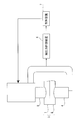
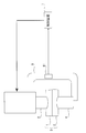
 なお、本発明において、最後の通電時間は、100ms以上300ms以下とすることが好ましい。上記の式で、最後の通電はN+1回目の通電を意味する。100ms未満の場合は、ナゲット形成が不十分となる。300msを超える時間の通電は施工性を悪化させるほか、ナゲット形成への寄与が小さい。最後の通電時間は、上記の範囲において、最初の通電と、その後の通電と休止の繰返しにかかる時間に合わせて、最適な通電時間を選択すればよい。 In the present invention, the last energization time is preferably 100 ms or more and 300 ms or less. In the above formula, the last energization means the (N + 1) th energization. If it is less than 100 ms, nugget formation is insufficient. Energization for a time exceeding 300 ms deteriorates workability and contributes little to nugget formation. The last energization time may be selected in accordance with the time required for the first energization and the subsequent energization and rest in the above range.
 なお、本発明に係る抵抗スポット溶接装置としては、図4および図5の構成に何ら限定されない。本発明に係る抵抗スポット溶接装置は、上下一対の電極を備え、当該一対の電極で溶接する部分を挟んで、加圧、通電がなされ、しかも溶接中の溶接電流を任意に制御可能な溶接電流制御装置を有していればよい。加圧機構(エアシリンダやサーボモータ等)や、電流制御機構(交流や直流等)、形式(定置式、ロボットガン等)等はとくに限定されない。 Note that the resistance spot welding apparatus according to the present invention is not limited to the configurations shown in FIGS. 4 and 5. A resistance spot welding apparatus according to the present invention includes a pair of upper and lower electrodes, a welding current that is pressurized and energized across a portion to be welded by the pair of electrodes, and that can arbitrarily control the welding current during welding. What is necessary is just to have a control apparatus. There are no particular limitations on the pressurizing mechanism (air cylinder, servo motor, etc.), current control mechanism (AC, DC, etc.), type (stationary, robot gun, etc.), etc.
 本発明は、亜鉛めっき鋼板や高強度鋼板を含む複数枚の板組の溶接装置に適用することが好ましい。亜鉛めっき鋼板や高強度鋼板は、通常の鋼板に比べると、板隙に起因した散りが発生しやすい。しかしながら、本発明は、散りの発生を抑制できるという効果を有するため、このような鋼板を少なくとも1枚含む板組の溶接に対して適用すると、より効果的である。 The present invention is preferably applied to a welding apparatus for a plurality of plates including a galvanized steel plate and a high-strength steel plate. Galvanized steel sheets and high-strength steel sheets are more likely to be scattered due to sheet gaps than ordinary steel sheets. However, since the present invention has an effect of suppressing the occurrence of scattering, it is more effective when applied to welding of a plate set including at least one such steel plate.
 そのため、溶接を行う板組のうち、少なくとも1枚の鋼板の引張強さが980MPa以上の高強度鋼板であっても、散りの発生を抑制し、大きなナゲット径を形成することができる。 Therefore, even if the tensile strength of at least one steel plate is 980 MPa or more among the plate sets to be welded, the occurrence of scattering can be suppressed and a large nugget diameter can be formed.
 溶接を行う板組のうち、少なくとも1枚の鋼板が、0.15≦C≦0.30(質量%)、1.9≦Mn≦5.0(質量%)、0.2≦Si≦2.0(質量%)の成分を有する引張強さが980MPa以上の高強度鋼板であっても、散りの発生を抑制し、大きなナゲット径を形成することができる。 Among the plate sets to be welded, at least one steel plate has 0.15 ≦ C ≦ 0.30 (mass%), 1.9 ≦ Mn ≦ 5.0 (mass%), 0.2 ≦ Si ≦ 2. Even a high strength steel sheet having a 0.0 (mass%) component and a tensile strength of 980 MPa or more can suppress the occurrence of scattering and form a large nugget diameter.
 また、溶接を行う板組のうち、少なくとも1枚の鋼板が、亜鉛めっき鋼板であっても、散りの発生を抑制し、大きなナゲット径を形成することができる。なお、亜鉛めっき鋼板とは、亜鉛を主成分とするめっき層を有する鋼板を示し、亜鉛を主成分とするめっき層には、従来から公知の亜鉛めっき層をすべて含むものとする。具体的には、亜鉛を主成分とするめっき層としては、溶融亜鉛めっき層や電気亜鉛めっき層をはじめとして、Alめっき層、Zn-Alめっき層やZn-Ni層等が含まれる。 Moreover, even if at least one steel plate among the plate sets to be welded is a galvanized steel plate, the occurrence of scattering can be suppressed and a large nugget diameter can be formed. In addition, a galvanized steel plate shows the steel plate which has a plating layer which has zinc as a main component, and all the conventionally well-known zinc plating layers are included in the plating layer which has zinc as a main component. Specifically, the plating layer containing zinc as a main component includes a hot dip galvanized layer, an electrogalvanized layer, an Al plated layer, a Zn—Al plated layer, a Zn—Ni layer, and the like.
 本発明に係る抵抗スポット溶接装置は、上記のように、加圧力を測定し、測定された加圧力に基づいて、通電中の加圧力を適切に制御しながら通電と休止を行うことによって、散りの発生を抑制し、大きなナゲットを形成することができる。そのため、板隙などの施工外乱が存在する場合でも、安定してナゲット径を確保することができる。 As described above, the resistance spot welding apparatus according to the present invention measures the applied pressure, and based on the measured applied pressure, performs energization and pause while appropriately controlling the applied pressure during energization. Generation can be suppressed, and a large nugget can be formed. For this reason, the nugget diameter can be stably secured even when there is a construction disturbance such as a sheet gap.
 本発明の実施例として、図5に示す装置を用い、2枚の合金化溶融亜鉛めっき鋼板(下の鋼板1、上の鋼板2)を重ねた板組3について、抵抗スポット溶接継手を作製した。具体的に、実施例で用いた装置は、サーボモータにより電極を加圧するCガンタイプの溶接装置である。なお、電源は、直流電源を用いた。 As an example of the present invention, a resistance spot welded joint was produced for a plate set 3 in which two alloyed hot-dip galvanized steel plates (lower steel plate 1 and upper steel plate 2) were stacked using the apparatus shown in FIG. . Specifically, the apparatus used in the examples is a C gun type welding apparatus that pressurizes an electrode with a servo motor. A DC power source was used as the power source.
 この時の通電は、表1に示す条件で行った。 The energization at this time was performed under the conditions shown in Table 1.
 また、電極4、5としては、先端の曲率半径R40mm、先端径8mmのアルミナ分散銅のDR型電極を用いた。さらに、試験片としては、引張強さ980MPa級の板厚0.8~2.6mm、1470MPa級の板厚2.0mmの高強度鋼板を使用した。同じ種類および板厚の鋼板を2枚重ねて溶接を行った。 Also, as the electrodes 4 and 5, DR-type electrodes of alumina-dispersed copper having a tip radius of curvature R of 40 mm and a tip diameter of 8 mm were used. Further, as a test piece, a high-strength steel plate having a tensile strength of 980 MPa class with a thickness of 0.8 to 2.6 mm and a 1470 MPa class with a thickness of 2.0 mm was used. Two steel plates of the same type and thickness were stacked and welded.
 通電中の加圧力はCガンに取付けたひずみ計61を用いて測定した。測定された加圧力が所定の値になるように通電を変化させた。 The applied pressure during energization was measured using a strain gauge 61 attached to the C gun. The energization was changed so that the measured applied pressure became a predetermined value.
 表1に、溶接を行った際の散り発生の有無、およびナゲット径について調べた結果を示す。なお、ナゲット径は切断断面のエッチング組織で評価した。ナゲット径の評価は、板厚をt(mm)として、5.5√t以上を○、5.5√t未満を×とした。すなわち、ナゲット径5.5√t以上を、適正径と設定した。 Table 1 shows the results of investigating the occurrence of scattering and the nugget diameter during welding. The nugget diameter was evaluated by the etching structure of the cut section. The nugget diameter was evaluated by assuming that the plate thickness was t (mm), and that ≧ 5.5√t was ○, and less than 5.5√t was ×. That is, a nugget diameter of 5.5√t or more was set as an appropriate diameter.
Figure JPOXMLDOC01-appb-T000001
 表1において、I(kA)は第1通電の電流値、T(ms)は第1通電の通電時間、F (1)/Fは、初期加圧力Fiに対する加圧力F (1)の比である。また、Tc(ms)は第1休止の時間、F (1)/Fは、初期加圧力Fiに対する加圧力F (1)の比、F (1)/F (1)は通電を休止する加圧力F (1)に対する通電を再開する加圧力F (1)の比である。また、I(kA)は第2通電の電流値、T(ms)は第2通電の通電時間である。 In Table 1, I 1 (kA) is the current value of the first energization, T 1 (ms) is the energization time of the first energization, and F h (1) / F i is the applied pressure F h ( The ratio of 1) . Tc 1 (ms) is the first pause time, F c (1) / F i is the ratio of the applied pressure F c (1) to the initial applied pressure Fi, and F c (1) / F h (1) Is the ratio of the applied pressure F c (1) at which energization is resumed to the applied pressure F h (1) at which energization is suspended. I 2 (kA) is the current value of the second energization, and T 2 (ms) is the energization time of the second energization.
 表1に示したとおり、本発明に係る抵抗スポット溶接装置により溶接を行った場合は、比較例に比べると、散りの発生がなく、また適正径のナゲットが形成されていることが分かる。 As shown in Table 1, when welding is performed by the resistance spot welding apparatus according to the present invention, it is understood that there is no occurrence of scattering and a nugget having an appropriate diameter is formed as compared with the comparative example.
 本発明の実施例として、3枚の合金化溶融亜鉛めっき鋼板を重ねた板組について、Cガンに取付けられたサーボモータ加圧式で直流電源を有する抵抗溶接機を用いて抵抗スポット溶接を行い、抵抗スポット溶接継手を作製した。 As an example of the present invention, resistance spot welding is performed using a resistance welding machine having a DC power supply with a servo motor pressurization type attached to a C gun, with respect to a plate assembly in which three alloyed hot-dip galvanized steel sheets are stacked. A resistance spot welded joint was prepared.
 この時の通電は、表2に示す条件で行った。 The energization at this time was performed under the conditions shown in Table 2.
 また、電極4、5としては、先端の曲率半径R40mm、先端径8mmのアルミナ分散銅のDR型電極を用いた。さらに、試験片としては、980MPa級の板厚0.8~2.3mm、1800MPa級の板厚1.2mmの高強度鋼板を使用した。同じ種類および板厚の鋼板を3枚重ねて溶接を行った。 Also, as the electrodes 4 and 5, DR-type electrodes of alumina-dispersed copper having a tip radius of curvature R of 40 mm and a tip diameter of 8 mm were used. Further, as the test piece, a high-strength steel plate having a plate thickness of 0.8 to 2.3 mm of the 980 MPa class and a thickness of 1.2 mm of the 1800 MPa class was used. Three steel plates of the same type and thickness were stacked and welded.
 通電中の加圧力はCガンに取付けたひずみ計を用いて測定した。計測加圧力が所定の値になるように加圧力を変化させた。 The applied pressure during energization was measured using a strain gauge attached to the C gun. The applied pressure was changed so that the measured applied pressure became a predetermined value.
 表2に、溶接を行った際の散り発生の有無、およびナゲット径について調べた結果を示す。なお、ナゲット径は切断断面のエッチング組織で評価した。ナゲット径の評価は、板厚をt(mm)として、5.5√t以上を○、5.5√t未満を×とした。すなわち、ナゲット径5.5√t以上を、適正径と設定した。 Table 2 shows the results of investigating the occurrence of scattering and the nugget diameter during welding. The nugget diameter was evaluated by the etching structure of the cut section. The nugget diameter was evaluated by assuming that the plate thickness was t (mm), and that ≧ 5.5√t was ○, and less than 5.5√t was ×. That is, a nugget diameter of 5.5√t or more was set as an appropriate diameter.
 さらに、同じ試験を10回繰返し行い、そのナゲット径の変動を評価した。適正径が得られており、ナゲット径の変動の幅が0.1√t以下になっている場合を◎とした。 Furthermore, the same test was repeated 10 times, and the fluctuation of the nugget diameter was evaluated. A case where an appropriate diameter was obtained and the width of fluctuation of the nugget diameter was 0.1√t or less was marked with ◎.
Figure JPOXMLDOC01-appb-T000002
 表2において、I(kA)は第1通電の電流値、T(ms)は第1通電の通電時間、F (1)/Fは、初期加圧力Fiに対する加圧力F (1)の比である。また、Tc(ms)は第1休止の時間、F (1)/Fは、初期加圧力Fiに対する加圧力F (1)の比、F (1)/F (1)は通電を休止する加圧力に対する通電を再開する加圧力の比である。同様に、F (2)/F (1)は一回目の休止直後の加圧力に対する第2通電後の通電休止時の加圧力の比、F (2)/F (1)は一回目の休止直後の加圧力に対する二回目の休止直後の加圧力の比、F (2)/F (2)は第2通電後の通電休止時の加圧力に対する二回目の休止直後の加圧力の比、I(kA)およびI(kA)は第2および第3通電の電流値、T(ms)およびT(ms)は第2および第3通電の通電時間、Tc(ms)は第2休止の時間、である。 In Table 2, I 1 (kA) is the current value of the first energization, T 1 (ms) is the energization time of the first energization, and F h (1) / F i is the applied pressure F h ( The ratio of 1) . Tc 1 (ms) is the first pause time, F c (1) / F i is the ratio of the applied pressure F c (1) to the initial applied pressure Fi, and F c (1) / F h (1) Is the ratio of the applied pressure at which energization is resumed to the applied pressure at which energization is suspended. Similarly, F h (2) / F c (1) is the ratio of the applied pressure during the energization stop after the second energization to the applied pressure immediately after the first stop, and F c (2) / F c (1) is The ratio of the pressing force immediately after the second pause to the pressing force immediately after the first pause, F c (2) / F h (2) is the value immediately after the second pause with respect to the pressing force at the time of the energization pause after the second energization. Pressure ratio, I 2 (kA) and I 3 (kA) are the current values of the second and third energizations, T 2 (ms) and T 3 (ms) are the energization times of the second and third energizations, and Tc 2 (ms) is the second pause time.
 表2に示したとおり、本発明に従い抵抗スポット溶接を行った場合は、比較例に比べると、散りの発生がなく、また適正径のナゲットが形成されていることが分かる。さらに、第2通電を本発明法の条件とすることにより、そうでない場合に比べて、ナゲット径が安定化する効果が示された。 As shown in Table 2, it can be seen that when resistance spot welding is performed according to the present invention, there is no occurrence of scattering and a nugget with an appropriate diameter is formed as compared with the comparative example. Furthermore, the effect of stabilizing the nugget diameter was shown by making the second energization a condition of the method of the present invention as compared with the case where it was not.
 1 下の鋼板
 2 上の鋼板
 3 板組
 4 下の電極
 5 上の電極
 6 加圧力計測装置
  61 ひずみ計
 7 制御装置
 8 ガンアーム
 9 ナゲット
DESCRIPTION OF SYMBOLS 1 Steel plate 2 Lower steel plate 3 Plate assembly 4 Lower electrode 5 Electrode 6 Force measuring device 61 Strain meter 7 Control device 8 Gun arm 9 Nugget

Claims (4)

  1.  二枚以上の鋼板を重ね合せた板組を、一対の溶接電極で挟持し、加圧しながら通電して溶接する抵抗スポット溶接装置であって、
     一対の電極と、
     電極による加圧力Fを測定する加圧力計測装置と、
     加圧力計測装置によって測定された加圧力Fに基づいて、電極間の通電を制御する制御装置を備え、
     制御装置は、加圧力計測装置によって測定された通電開始後の加圧力Fが、初期加圧力Fiに対し、通電開始からの経過時間が20ms以上80ms以下の間で式(1)に示す加圧力F (1)となったら、20ms以上60ms以下の通電の休止を行い、
     その後、加圧力Fが、式(2)に示す加圧力F (1)となったら、再度通電を開始するように通電を制御する抵抗スポット溶接装置。
    1.03×Fi≦F (1)≦1.15×Fi     (1)
    1.01×Fi≦F (1)≦0.99×F (1)     (2)
    A resistance spot welding apparatus that welds a pair of two or more steel plates, sandwiched between a pair of welding electrodes and energized while being pressurized,
    A pair of electrodes;
    A pressure measuring device for measuring the pressure F applied by the electrodes;
    Based on the applied pressure F measured by the applied pressure measuring device, a control device for controlling energization between the electrodes is provided,
    The control device applies the pressurization force expressed by the formula (1) when the applied pressure F measured by the applied pressure measuring device is between 20 ms and 80 ms with respect to the initial applied force Fi. When F h (1) is reached, stop energization for 20 ms or more and 60 ms or less,
    Thereafter, when the applied pressure F becomes the applied pressure F c (1) shown in Expression (2), the resistance spot welding apparatus controls the energization so that the energization is started again.
    1.03 × Fi ≦ F h (1) ≦ 1.15 × Fi (1)
    1.01 × Fi ≦ F c (1) ≦ 0.99 × F h (1) (2)
  2.  請求項1に記載の抵抗スポット溶接装置であって、
     制御装置はさらに、
     前記通電の休止後に、20ms以上80ms以下の通電と、20ms以上60ms以下の休止を1回以上繰り返し、
     (N-1)回目の休止直後の加圧力F (N-1)に対して、加圧力FがN回目の通電により式(3)に示す加圧力F (N)となったら、通電を休止し、
     その後、加圧力Fが、式(4)に示す加圧力F (N)に到達となったら、再度通電を開始するように通電を制御する抵抗スポット溶接装置。
    1.04×F (N-1)≦F (N)≦1.15×F (N-1)     (3)
    (N-1)≦F (N)≦0.99×F (N)     (4)
    N:2以上の自然数
    The resistance spot welding apparatus according to claim 1,
    The control device further
    After stopping the energization, the energization for 20 ms to 80 ms and the pause for 20 ms to 60 ms are repeated once or more,
    (N-1) With respect to the applied pressure F c (N-1) immediately after the pause, the energization is performed when the applied pressure F becomes the applied pressure F h (N) shown in the equation (3) by the Nth energization. Pause
    Thereafter, when the applied pressure F reaches the applied pressure F c (N) shown in Expression (4), the resistance spot welding apparatus controls the energization so that the energization is started again.
    1.04 × F c (N−1) ≦ F h (N) ≦ 1.15 × F c (N−1) (3)
    F c (N−1) ≦ F c (N) ≦ 0.99 × F h (N) (4)
    N: Natural number of 2 or more
  3.  請求項1または2に記載の抵抗スポット溶接装置であって、制御装置は、最後のN+1回目の通電時間は100ms以上300ms以下となるように通電を制御する抵抗スポット溶接装置。 3. The resistance spot welding apparatus according to claim 1, wherein the control device controls energization so that the last N + 1-th energization time is 100 ms or more and 300 ms or less.
  4.  請求項1から3のうちいずれかに記載の抵抗スポット溶接装置であって、
     一対の電極が設置されたガンアームをさらに備え、
     加圧力計測装置は、ガンアームのひずみを測定するひずみ計である抵抗スポット溶接装置。
    The resistance spot welding apparatus according to any one of claims 1 to 3,
    It further comprises a gun arm on which a pair of electrodes are installed,
    The pressure measuring device is a resistance spot welding device that is a strain gauge that measures the strain of the gun arm.
PCT/JP2016/001174 2015-03-05 2016-03-03 Resistance spot welding device WO2016139952A1 (en)

Priority Applications (6)

Application Number Priority Date Filing Date Title
EP16758648.6A EP3266554B1 (en) 2015-03-05 2016-03-03 Resistance spot welding device
US15/555,135 US10722972B2 (en) 2015-03-05 2016-03-03 Resistance spot welding device
KR1020177024489A KR101946307B1 (en) 2015-03-05 2016-03-03 Resistance spot welding device
CN201680013283.0A CN107405715B (en) 2015-03-05 2016-03-03 Resistance spot welding device
JP2016537581A JP6079934B2 (en) 2015-03-05 2016-03-03 Resistance spot welding equipment
MX2017011319A MX2017011319A (en) 2015-03-05 2016-03-03 Resistance spot welding device.

Applications Claiming Priority (4)

Application Number Priority Date Filing Date Title
JP2015043053 2015-03-05
JP2015-043053 2015-03-05
JP2015-071650 2015-03-31
JP2015071650 2015-03-31

Publications (1)

Publication Number Publication Date
WO2016139952A1 true WO2016139952A1 (en) 2016-09-09

Family

ID=56849340

Family Applications (1)

Application Number Title Priority Date Filing Date
PCT/JP2016/001174 WO2016139952A1 (en) 2015-03-05 2016-03-03 Resistance spot welding device

Country Status (7)

Country Link
US (1) US10722972B2 (en)
EP (1) EP3266554B1 (en)
JP (1) JP6079934B2 (en)
KR (1) KR101946307B1 (en)
CN (1) CN107405715B (en)
MX (1) MX2017011319A (en)
WO (1) WO2016139952A1 (en)

Cited By (2)

* Cited by examiner, † Cited by third party
Publication number Priority date Publication date Assignee Title
JP6079935B2 (en) * 2015-03-05 2017-02-15 Jfeスチール株式会社 Resistance spot welding method
JP2020171942A (en) * 2019-04-11 2020-10-22 トヨタ自動車株式会社 Resistance spot welding device

Families Citing this family (3)

* Cited by examiner, † Cited by third party
Publication number Priority date Publication date Assignee Title
WO2016208610A1 (en) * 2015-06-26 2016-12-29 本田技研工業株式会社 Spot welding method and device
JP7468418B2 (en) * 2021-03-18 2024-04-16 トヨタ自動車株式会社 Welding determination method and spot welding device
WO2023002239A1 (en) * 2021-07-23 2023-01-26 Arcelormittal A welding method

Citations (3)

* Cited by examiner, † Cited by third party
Publication number Priority date Publication date Assignee Title
JPH11333566A (en) * 1998-05-25 1999-12-07 Kanto Auto Works Ltd Spot welding equipment
JP2012125808A (en) * 2010-12-15 2012-07-05 Nissan Motor Co Ltd Bonding method and bonding device
JP2012187639A (en) * 2008-10-16 2012-10-04 Jfe Steel Corp Resistance spot welding method for high-strength steel sheet

Family Cites Families (28)

* Cited by examiner, † Cited by third party
Publication number Priority date Publication date Assignee Title
JPS59185581A (en) * 1983-04-07 1984-10-22 フオルクスウア−ゲンウエルク・アクチエンゲゼルシヤフト Resistance spot welding method and apparatus
US4694135A (en) * 1986-07-09 1987-09-15 General Motors Corporation Method and apparatus for monitoring and controlling resistance spot welding
JPH1058157A (en) 1996-06-13 1998-03-03 Kawasaki Heavy Ind Ltd Method and device for spot welding
JP3588668B2 (en) * 1997-08-27 2004-11-17 日産自動車株式会社 Estimation method of nugget diameter in spot welding
US6515251B1 (en) * 2000-10-31 2003-02-04 Steelcase Development Corporation Welding system and method
JP3849539B2 (en) 2002-02-19 2006-11-22 Jfeスチール株式会社 Spot welding method for high-tensile galvanized steel sheet
AT413504B (en) 2002-07-03 2006-03-15 Fronius Int Gmbh ELECTRODE PROTECTION DEVICE
JP3922263B2 (en) 2004-03-17 2007-05-30 Jfeスチール株式会社 Method of manufacturing resistance spot welded joint
JP2007321182A (en) * 2006-05-31 2007-12-13 Nisshin Steel Co Ltd Automobile member having high collision absorbing performance
JP4728926B2 (en) 2006-10-16 2011-07-20 新日本製鐵株式会社 Lap resistance spot welding method
JP2008229720A (en) * 2007-02-22 2008-10-02 Kobe Steel Ltd Spot-welded joint of high-strength steel sheets excellent in tensile strength, automotive component having the same joint, and spot-welding method of high-strength steel sheets
JP5045238B2 (en) 2007-05-23 2012-10-10 Jfeスチール株式会社 Resistance spot welding method
KR101289370B1 (en) 2008-09-30 2013-07-29 도쿠리츠교세이호징 붓시쯔 자이료 겐큐키코 Welding device for metal and welding method for metal
JP5168204B2 (en) 2008-10-08 2013-03-21 新日鐵住金株式会社 Spot welding method for steel sheet
JP5415896B2 (en) 2009-01-29 2014-02-12 Jfeスチール株式会社 Indirect spot welding method
IN2012DN01208A (en) 2009-08-31 2015-04-10 Nippon Steel Corp
JP2011152574A (en) 2010-01-28 2011-08-11 Honda Motor Co Ltd Resistance welding method
JP5392142B2 (en) 2010-02-22 2014-01-22 新日鐵住金株式会社 Spot welding method for alloyed aluminized steel sheet or press part having aluminum alloy layer
JP5149355B2 (en) 2010-09-08 2013-02-20 富士重工業株式会社 Spot welding method and spot welding apparatus
JP5549618B2 (en) * 2011-02-15 2014-07-16 新日鐵住金株式会社 High strength steel plate for spot welding with a tensile strength of 980 MPa or more
WO2012168564A1 (en) 2011-06-07 2012-12-13 Arcelormittal Investigación Y Desarrollo Sl Cold-rolled steel plate coated with zinc or a zinc alloy, method for manufacturing same, and use of such a steel plate
JP5498463B2 (en) 2011-10-13 2014-05-21 富士重工業株式会社 Pressure control method for spot welding equipment
JP5333560B2 (en) 2011-10-18 2013-11-06 Jfeスチール株式会社 Resistance spot welding method and resistance spot welding joint of high strength steel plate
CN102581459B (en) 2012-03-07 2014-06-25 上海交通大学 Electric resistance welding method for variable-thickness ultra-high strength hot formed steel plate and low-carbon steel plate
DE102012025200A1 (en) * 2012-12-27 2014-07-03 Robert Bosch Gmbh Welding process for welding aluminum
JP6001478B2 (en) 2013-03-19 2016-10-05 株式会社神戸製鋼所 Spot welded joint
MY174502A (en) 2013-07-11 2020-04-23 Nippon Steel Corp Resistance spot welding method
CN107427953B (en) * 2015-03-05 2019-10-08 杰富意钢铁株式会社 Resistance spot welding method and welding point

Patent Citations (3)

* Cited by examiner, † Cited by third party
Publication number Priority date Publication date Assignee Title
JPH11333566A (en) * 1998-05-25 1999-12-07 Kanto Auto Works Ltd Spot welding equipment
JP2012187639A (en) * 2008-10-16 2012-10-04 Jfe Steel Corp Resistance spot welding method for high-strength steel sheet
JP2012125808A (en) * 2010-12-15 2012-07-05 Nissan Motor Co Ltd Bonding method and bonding device

Non-Patent Citations (1)

* Cited by examiner, † Cited by third party
Title
See also references of EP3266554A4 *

Cited By (2)

* Cited by examiner, † Cited by third party
Publication number Priority date Publication date Assignee Title
JP6079935B2 (en) * 2015-03-05 2017-02-15 Jfeスチール株式会社 Resistance spot welding method
JP2020171942A (en) * 2019-04-11 2020-10-22 トヨタ自動車株式会社 Resistance spot welding device

Also Published As

Publication number Publication date
US10722972B2 (en) 2020-07-28
KR101946307B1 (en) 2019-02-11
EP3266554A1 (en) 2018-01-10
CN107405715A (en) 2017-11-28
JP6079934B2 (en) 2017-02-15
EP3266554A4 (en) 2018-03-14
MX2017011319A (en) 2017-12-07
US20180043461A1 (en) 2018-02-15
JPWO2016139952A1 (en) 2017-04-27
CN107405715B (en) 2019-10-08
KR20170109045A (en) 2017-09-27
EP3266554B1 (en) 2021-08-11

Similar Documents

Publication Publication Date Title
JP6079935B2 (en) Resistance spot welding method
JP6079934B2 (en) Resistance spot welding equipment
JP6094676B2 (en) Resistance spot welding method
JP5854172B2 (en) Resistance spot welding method
JP6278154B2 (en) Resistance spot welding method and manufacturing method of welded member
WO2019124467A1 (en) Method for manufacturing resistance spot welded joint
WO2019124464A1 (en) Method for manufacturing resistance spot welded joint
JP6160581B2 (en) Resistance spot welding method
EP3342524B1 (en) Resistance spot welding method and method for manufacturing welded member
WO2018159764A1 (en) Resistance spot welding method
CN110475642B (en) Method for manufacturing resistance spot-welded joint
WO2019124465A1 (en) Method for manufacturing resistance spot welded joint
WO2023008263A1 (en) Resistance spot welding method
JP6372639B1 (en) Resistance spot welding method
JP7355282B1 (en) Welded joints, welded parts and manufacturing methods thereof, and resistance spot welding methods
WO2021059720A1 (en) Resistance spot welding method and method of manufacturing resistance spot welded joint

Legal Events

Date Code Title Description
ENP Entry into the national phase

Ref document number: 2016537581

Country of ref document: JP

Kind code of ref document: A

121 Ep: the epo has been informed by wipo that ep was designated in this application

Ref document number: 16758648

Country of ref document: EP

Kind code of ref document: A1

REEP Request for entry into the european phase

Ref document number: 2016758648

Country of ref document: EP

ENP Entry into the national phase

Ref document number: 20177024489

Country of ref document: KR

Kind code of ref document: A

WWE Wipo information: entry into national phase

Ref document number: 15555135

Country of ref document: US

WWE Wipo information: entry into national phase

Ref document number: MX/A/2017/011319

Country of ref document: MX

NENP Non-entry into the national phase

Ref country code: DE