WO2016139853A1 - ハイブリッド式作業機械 - Google Patents
ハイブリッド式作業機械 Download PDFInfo
- Publication number
- WO2016139853A1 WO2016139853A1 PCT/JP2015/083131 JP2015083131W WO2016139853A1 WO 2016139853 A1 WO2016139853 A1 WO 2016139853A1 JP 2015083131 W JP2015083131 W JP 2015083131W WO 2016139853 A1 WO2016139853 A1 WO 2016139853A1
- Authority
- WO
- WIPO (PCT)
- Prior art keywords
- engine
- speed
- torque
- control
- output
- Prior art date
Links
Images


Classifications
-
- F—MECHANICAL ENGINEERING; LIGHTING; HEATING; WEAPONS; BLASTING
- F02—COMBUSTION ENGINES; HOT-GAS OR COMBUSTION-PRODUCT ENGINE PLANTS
- F02D—CONTROLLING COMBUSTION ENGINES
- F02D29/00—Controlling engines, such controlling being peculiar to the devices driven thereby, the devices being other than parts or accessories essential to engine operation, e.g. controlling of engines by signals external thereto
- F02D29/06—Controlling engines, such controlling being peculiar to the devices driven thereby, the devices being other than parts or accessories essential to engine operation, e.g. controlling of engines by signals external thereto peculiar to engines driving electric generators
-
- B—PERFORMING OPERATIONS; TRANSPORTING
- B60—VEHICLES IN GENERAL
- B60L—PROPULSION OF ELECTRICALLY-PROPELLED VEHICLES; SUPPLYING ELECTRIC POWER FOR AUXILIARY EQUIPMENT OF ELECTRICALLY-PROPELLED VEHICLES; ELECTRODYNAMIC BRAKE SYSTEMS FOR VEHICLES IN GENERAL; MAGNETIC SUSPENSION OR LEVITATION FOR VEHICLES; MONITORING OPERATING VARIABLES OF ELECTRICALLY-PROPELLED VEHICLES; ELECTRIC SAFETY DEVICES FOR ELECTRICALLY-PROPELLED VEHICLES
- B60L50/00—Electric propulsion with power supplied within the vehicle
- B60L50/10—Electric propulsion with power supplied within the vehicle using propulsion power supplied by engine-driven generators, e.g. generators driven by combustion engines
- B60L50/16—Electric propulsion with power supplied within the vehicle using propulsion power supplied by engine-driven generators, e.g. generators driven by combustion engines with provision for separate direct mechanical propulsion
-
- B—PERFORMING OPERATIONS; TRANSPORTING
- B60—VEHICLES IN GENERAL
- B60W—CONJOINT CONTROL OF VEHICLE SUB-UNITS OF DIFFERENT TYPE OR DIFFERENT FUNCTION; CONTROL SYSTEMS SPECIALLY ADAPTED FOR HYBRID VEHICLES; ROAD VEHICLE DRIVE CONTROL SYSTEMS FOR PURPOSES NOT RELATED TO THE CONTROL OF A PARTICULAR SUB-UNIT
- B60W10/00—Conjoint control of vehicle sub-units of different type or different function
- B60W10/04—Conjoint control of vehicle sub-units of different type or different function including control of propulsion units
- B60W10/08—Conjoint control of vehicle sub-units of different type or different function including control of propulsion units including control of electric propulsion units, e.g. motors or generators
-
- B—PERFORMING OPERATIONS; TRANSPORTING
- B60—VEHICLES IN GENERAL
- B60W—CONJOINT CONTROL OF VEHICLE SUB-UNITS OF DIFFERENT TYPE OR DIFFERENT FUNCTION; CONTROL SYSTEMS SPECIALLY ADAPTED FOR HYBRID VEHICLES; ROAD VEHICLE DRIVE CONTROL SYSTEMS FOR PURPOSES NOT RELATED TO THE CONTROL OF A PARTICULAR SUB-UNIT
- B60W10/00—Conjoint control of vehicle sub-units of different type or different function
- B60W10/30—Conjoint control of vehicle sub-units of different type or different function including control of auxiliary equipment, e.g. air-conditioning compressors or oil pumps
-
- B—PERFORMING OPERATIONS; TRANSPORTING
- B60—VEHICLES IN GENERAL
- B60W—CONJOINT CONTROL OF VEHICLE SUB-UNITS OF DIFFERENT TYPE OR DIFFERENT FUNCTION; CONTROL SYSTEMS SPECIALLY ADAPTED FOR HYBRID VEHICLES; ROAD VEHICLE DRIVE CONTROL SYSTEMS FOR PURPOSES NOT RELATED TO THE CONTROL OF A PARTICULAR SUB-UNIT
- B60W20/00—Control systems specially adapted for hybrid vehicles
-
- E—FIXED CONSTRUCTIONS
- E02—HYDRAULIC ENGINEERING; FOUNDATIONS; SOIL SHIFTING
- E02F—DREDGING; SOIL-SHIFTING
- E02F9/00—Component parts of dredgers or soil-shifting machines, not restricted to one of the kinds covered by groups E02F3/00 - E02F7/00
- E02F9/20—Drives; Control devices
-
- F—MECHANICAL ENGINEERING; LIGHTING; HEATING; WEAPONS; BLASTING
- F02—COMBUSTION ENGINES; HOT-GAS OR COMBUSTION-PRODUCT ENGINE PLANTS
- F02D—CONTROLLING COMBUSTION ENGINES
- F02D29/00—Controlling engines, such controlling being peculiar to the devices driven thereby, the devices being other than parts or accessories essential to engine operation, e.g. controlling of engines by signals external thereto
- F02D29/04—Controlling engines, such controlling being peculiar to the devices driven thereby, the devices being other than parts or accessories essential to engine operation, e.g. controlling of engines by signals external thereto peculiar to engines driving pumps
-
- Y—GENERAL TAGGING OF NEW TECHNOLOGICAL DEVELOPMENTS; GENERAL TAGGING OF CROSS-SECTIONAL TECHNOLOGIES SPANNING OVER SEVERAL SECTIONS OF THE IPC; TECHNICAL SUBJECTS COVERED BY FORMER USPC CROSS-REFERENCE ART COLLECTIONS [XRACs] AND DIGESTS
- Y02—TECHNOLOGIES OR APPLICATIONS FOR MITIGATION OR ADAPTATION AGAINST CLIMATE CHANGE
- Y02T—CLIMATE CHANGE MITIGATION TECHNOLOGIES RELATED TO TRANSPORTATION
- Y02T10/00—Road transport of goods or passengers
- Y02T10/60—Other road transportation technologies with climate change mitigation effect
- Y02T10/70—Energy storage systems for electromobility, e.g. batteries
Definitions
- the present invention relates to a hybrid work machine, and more particularly to a hybrid work machine such as a small hydraulic excavator.
- a generator / motor is provided as an auxiliary power source of a hydraulic pump driven by an engine, and power generation /
- the electric motor is driven as an electric motor, and output assist and battery (power storage device) charge control are performed so that the engine is operated at a rotational speed corresponding to the optimum torque.
- the fuel injection amount or engine speed at the optimum torque point at which the minimum fuel consumption is achieved is set as the target fuel injection amount (Patent Document 1) or target speed (Patent Document 2).
- the generator / motor is driven as an electric motor and output assist is performed.
- the generator / motor is driven as a generator, Battery charge control is performed.
- Patent Documents 3 and 4 the engine speed at the average output of the engine (Patent Document 3) or a preset engine speed (Patent Document 4) is set as a reference, and the engine speed becomes smaller than the engine speed.
- the generator / motor is driven as an electric motor to perform output assist.
- the generator / motor is driven as a generator to control charging of the battery.
- the rated torque of the engine is set as a reference, and when the absorption torque of the hydraulic pump driven by the engine becomes larger than the rated torque, the generator / motor is driven as an electric motor, output assist is performed, and absorption of the hydraulic pump is performed. When the torque is smaller than the rated torque, the generator / motor is driven as a generator to control the charging of the battery.
- Patent Documents 3 and 5 electric power is generated by driving an electric motor as a generator by regenerative energy at the time of boom lowering or turning braking, and the generated power is stored in the battery to restore the charged state of the battery. A method is described. In Patent Document 5, the average required horsepower of the engine is thereby reduced, and the engine can be downsized.
- the absorption torque of the hydraulic pump is used as an index for determining whether or not the output assist is being performed, it is difficult to accurately acquire the absorption torque of the hydraulic pump, and the actual rated torque that is the comparison target Since it varies depending on the environment such as altitude (atmospheric pressure), it cannot be accurately determined whether output assist is required.
- a small construction machine such as a mini excavator has a smaller space on the revolving frame than a medium-sized or large-sized construction machine.
- it is very difficult in terms of layout. For this reason, it is desirable to reduce not only the engine but also the battery (power storage device) as much as possible. For this reason, when the technique of Patent Document 5 is applied to such a small hydraulic excavator, the remaining charge of the battery is quickly reduced to the limit value, and the frequency of interrupting work for charging the battery is increased. The operating rate of the aircraft will be reduced.
- the present invention has been made in view of the above problems, and its purpose is to improve fuel efficiency and reduce exhaust gas characteristics by adopting a hybrid system and downsizing an engine in a small construction machine such as a mini excavator.
- a hybrid system and downsizing an engine in a small construction machine such as a mini excavator.
- To improve the power consumption and reduce the noise secure an installation space for the power storage device, and even if the power storage device is small, an early decrease in the remaining charge of the power storage device can be suppressed, so that the power storage device can be charged. It is providing the hybrid type working machine which can improve the operation rate of a body by reducing the frequency which interrupts.
- the present invention provides an engine, a hydraulic pump driven by the engine, a plurality of hydraulic actuators driven by pressure oil discharged from the hydraulic pump, and a target rotational speed of the engine
- the engine speed indicating device for instructing the engine, the engine speed detecting device for detecting the actual engine speed, and the fuel of the engine so as to increase as the deviation between the target engine speed and the actual engine speed increases.
- a governor device for adjusting the injection amount, and the governor device increases the load torque of the engine by increasing the fuel injection amount as the deviation between the target rotational speed and the actual rotational speed increases.
- a hybrid work machine that controls the output torque of the engine to increase as the engine is connected.
- the output horsepower of the engine is maximized when the target rotational speed indicated by the engine rotational speed indicating device is maximum, and the power storage device that transfers power between the generated power generator / motor, the power generator / motor
- the engine speed is set in advance as a rated speed, and the engine speed is maintained at the rated speed when the engine speed detected by the engine speed detector decreases below the rated speed.
- the first generator assist motor is operated as an electric motor so that the hydraulic pump is controlled to perform assist driving, and the first output assist control is performed.
- a controller that performs first charging control for operating the power generator / motor as a generator by surplus torque of the engine and charging the power storage device; And those were.
- the hybrid system is adopted to downsize the engine (particularly, the maximum torque of the engine is smaller than the maximum absorption torque of the hydraulic pump, and only the output torque of the engine). Then, by downsizing the engine to a size that cannot cover the maximum absorption torque of the hydraulic pump), it is possible to improve fuel consumption, improve exhaust gas characteristics, and reduce noise. Further, even a small work machine such as a mini excavator can secure an installation space for the power storage device.
- the output of the hydraulic pump 21 during normal operation is smaller than that during high-speed traveling, and therefore the output of the hydraulic pump during normal operation is reduced even when the engine is downsized. In many cases, it can be covered by an output that is less than the rated torque.
- output assist control is performed when the engine speed drops below the rated speed, and charge control is performed when the engine speed is greater than the rated speed (the engine has surplus torque). By doing so, the frequency of the output assist control is reduced and the power consumption of the battery is suppressed.
- the frequency of battery charge control can be increased without reducing the work efficiency, and the amount of charge of the battery can be increased.
- the battery is reduced to a size that can be mounted in a narrow space on the turning frame. Even if this is done, an early decrease in the remaining charge of the battery can be suppressed, and the operating rate of the aircraft can be improved by reducing the frequency of interrupting work for charging the power storage device.
- the fuel consumption is improved, the exhaust gas characteristics are improved, and the noise is reduced.
- by reducing the frequency of output assist control, increasing the frequency of charge control, and reducing the power consumption of the power storage device charging is possible even if the power storage device is reduced to a size that can be installed in a small space of a small construction machine. An early decrease in the remaining amount can be suppressed, and the operation rate of the aircraft can be improved by reducing the frequency of interruption of work for charging the power storage device.
- FIG. 1 is an external view of a hydraulic excavator according to a first embodiment of the present invention. It is a figure which shows the hybrid drive system of the hydraulic shovel which concerns on the 1st Embodiment of this invention. It is a figure which shows the fuel injection quantity characteristic used when an engine controller calculates fuel injection quantity.
- FIG. 4 is a diagram showing output torque characteristics of the engine when the fuel injection amount is controlled as shown in FIG. 3. It is a figure which shows the detail of a structure of a pump regulator. It is a pump torque characteristic figure which shows the function of the torque control part of a pump regulator. It is a figure which shows the hydraulic circuit part regarding the right and left traveling hydraulic motor among the hydraulic control valve and a plurality of hydraulic actuators.
- FIG. 1 It is a figure which shows the hybrid drive system of the hydraulic shovel in the 3rd Embodiment of this invention. It is a figure which shows the detail of a structure of a pump regulator. It is a pump torque characteristic figure by torque control of a pump regulator. It is a flowchart which shows the control function of the vehicle body controller in this Embodiment. As a comparative example, it is a figure which shows the change (the amount of torque reduction) of the maximum absorption torque of the hydraulic pump at the time of performing quick charge control only by pump torque reduction control.
- FIG. It is a figure which shows the change (decrease torque amount) of the maximum absorption torque of the hydraulic pump 21 in the case of performing quick charge control by engine speed reduction control and pump reduction torque control in this Embodiment. It is a figure which shows the amount of torque reduction required in this Embodiment, the surplus torque of the engine 11 at that time, and distribution of the largest torque which can be used for an operation
- FIG. 1 is an external view of a small hydraulic excavator that is a hybrid work machine according to a first embodiment of the present invention.
- a small-sized hydraulic excavator means a hydraulic excavator of an 8-ton class or less including a mini excavator.
- the hydraulic excavator includes a lower traveling body 101, an upper revolving body 102 that is turnably mounted on the lower traveling body 101, and a top portion of the upper revolving body 102 that rotates in the vertical and horizontal directions via a swing post 103. And a front work machine 104 that is movably connected.
- the lower traveling body 101 is of a crawler type, and a blade 106 for earth removal that can move up and down is provided on the front side of the track frame 105.
- the upper swivel body 102 includes a swivel base 107 having a basic lower structure, and a cabin (operator's cab) 108 provided on the swivel base 107.
- the front work machine 104 includes a boom 111, an arm 112, and a bucket 113.
- the base end of the boom 111 is pin-coupled to the swing post 103, and the tip of the boom 111 is pin-coupled to the base end of the arm 112. The tip of each is pin-coupled to the bucket 113.
- the upper turning body 102 is driven to turn by the turning motor (not shown) with respect to the lower traveling body 101, and the swing post 103 and the front work machine 104 are turned to the left and right by the swing cylinder 24g with respect to the turning table 107, and the boom 111,
- the arm 112 and the bucket 113 are driven to rotate up and down by expanding and contracting the boom cylinder 24c, the arm cylinder 24d, and the bucket cylinder 24e, respectively.
- the lower traveling body 101 is rotationally driven by left and right traveling motors 24a and 24b, and the blade 106 is driven up and down by a blade cylinder 24h.
- FIG. 2 is a diagram showing a hybrid drive system of the excavator shown in FIG.
- the hybrid drive system includes an engine system 1, a hydraulic system 2, a generator motor system 3, and a control system 4.
- the engine system 1 includes a diesel engine 11, an engine control dial 12, an engine controller 13, an electronic governor 14, and an engine speed detector 15.
- the diesel engine 11 is an engine downsized (smaller engine output) than the conventional one.
- the engine control dial 12 is used for instructing the target rotational speed of the engine 11 by the operation of the operator.
- the target speed is the engine speed when no load is applied to the engine 11.
- the engine controller 13 inputs a target rotational speed signal from the engine control dial 12, performs a predetermined calculation process to obtain a target fuel injection amount, and controls the electronic governor 14 to control the fuel injected into each cylinder of the engine.
- the injection amount is controlled, and the engine output torque and the engine speed are controlled.
- droop control that increases the fuel injection amount while decreasing the engine speed in accordance with an increase in engine load is adopted as the control of the electronic governor 14.
- the engine speed detection device 15 detects the actual speed of the engine 11.
- the engine speed detected by the engine speed detector 15 is input to the vehicle body controller 46 (described later) via the engine controller 13.
- FIG. 3 is a diagram showing a fuel injection amount characteristic used when the engine controller 13 calculates the fuel injection amount.
- the horizontal axis represents the deviation ⁇ N between the target rotational speed indicated by the engine control dial 12 and the actual rotational speed of the engine 11 detected by the engine rotational speed detection device 15, and the vertical axis represents the fuel injection amount F.
- the fuel injection amount characteristic when the rotational speed deviation ⁇ N is zero, the fuel injection amount F is the minimum Fmin, and as the rotational speed deviation ⁇ N increases, the fuel injection amount F follows the characteristic of the oblique straight line F1. It is set to increase linearly.
- the fuel injection amount F becomes the maximum Fmax, and when the rotational speed deviation ⁇ N further increases, the fuel injection amount F is held at a constant value of the maximum Fmax.
- a fuel injection amount characteristic is stored for each target rotational speed, a corresponding fuel injection amount characteristic is selected according to the target rotational speed indicated by the engine control dial 12, and the rotational speed calculated at that time is selected.
- the fuel injection amount corresponding to the deviation ⁇ N is obtained with reference to the fuel injection amount characteristic, the fuel injection amount is given as a target value to the electronic governor 14, and the fuel injection amount injected into each cylinder of the engine 11 is controlled.
- FIG. 4 is a diagram showing the output torque characteristics of the engine 11 when the fuel injection amount is controlled as described above, and is when the target rotational speed indicated by the engine control dial 12 is maximum.
- the horizontal axis represents the engine speed
- the vertical axis represents the engine output torque.
- the output torque characteristic of the engine 11 includes a full load characteristic Tf when the fuel injection amount is maximum, and a regulation characteristic Tgmax in which the fuel injection amount is adjusted based on the fuel injection characteristic shown in FIG.
- the total load characteristic Tf is determined by the characteristics of the engine 11, and as the engine speed decreases, the output torque of the engine 11 increases to the maximum TEmaxe, and the engine speed further decreases.
- the regulation characteristic Tgmax corresponds to the fuel injection characteristic shown in FIG. 3 and is a droop control characteristic in which the output torque of the engine 11 increases as the engine speed decreases.
- the fuel injection amount is the minimum Fmin
- the engine speed at this time is the NTmax at the intersection of the straight line of the regulation characteristic Tgmax and the horizontal axis.
- the regulation characteristic Tgmax increases linearly along an oblique straight line.
- the intersection between the straight line of the regulation characteristic Tgmax and the full load characteristic Tf is a point (described later) at which the fuel injection amount is maximum Fmax and the output horsepower of the engine 11 is maximum (described later), and the rotation speed (maximum horsepower rotation speed) NRmax at this time Is the rated speed, and the output torque Topt of the engine 11 is the rated torque.
- the engine controller 13 selects a fuel injection characteristic corresponding to each of the target rotational speeds NTx1, NTx2, and sets the fuel injection amount.
- the regulation characteristics change to the broken lines Tg1 and Tg2.
- the maximum horsepower rotation speed decreases to NR1 and NR2 (described later).
- the target rotational speed indicated by the engine control dial 12 is defined as the rotational speeds NTmax, NTx1, NTx2 when no load is applied to the engine 11, but the target rotational speed is the maximum horsepower rotational speed.
- NRmax, NR1 and NR2 may be defined as (the rated speed when the target speed indicated by the engine control dial 12 is maximum).
- the regulation characteristic is a droop control characteristic. However, the regulation characteristic adjusts the fuel injection amount so that the engine speed is kept constant regardless of the increase in engine load. It may be isochronous control characteristics (described later).
- the output shaft of the engine 11 is connected to the hydraulic system 2 and the generator motor system 3 through a power distributor 6 including a large diameter gear 6a and a small diameter gear 6b.
- the hydraulic system 2 includes a hydraulic pump 21 and a pilot pump 22, a control valve 23, a plurality of hydraulic actuators 24a to 24h, and a plurality of operating devices 25 and 26.
- the hydraulic pump 21 is connected to the output shaft of the engine 11 via the power distributor 6 and is driven by the engine 11.
- the pressure oil discharged from the hydraulic pump 21 is supplied to the plurality of hydraulic actuators 24a to 24h via the control valve 23, and drives each driven body.
- the hydraulic pump 21 is a variable displacement type, and includes a displacement displacement variable mechanism (for example, a swash plate) 21a and a pump regulator 27 that adjusts the tilt position of the displacement displacement variable mechanism 21a and controls the displacement of the hydraulic pump.
- the plurality of hydraulic actuators 24a to 24h include left and right traveling hydraulic motors and other hydraulic actuators.
- Other hydraulic actuators include, for example, a boom hydraulic cylinder, an arm hydraulic cylinder, a bucket hydraulic cylinder, a swing Includes hydraulic cylinders for blades and hydraulic cylinders for blades.
- the control valve 23 incorporates a plurality of main spools corresponding to the plurality of hydraulic actuators 24a to 24h, and these main spools are switched by hydraulic signals output from the operation devices 25 and 26.
- the operating device 25 is representative of left and right traveling operating devices, and the operating device 26 is representative of operating devices other than traveling.
- the generator motor system 3 includes a generator / motor 31, an inverter 32, a battery (power storage device) 33, a battery controller 34, and an operation panel 35.
- the generator / motor 31 is connected to the output shaft of the engine 11 via the power distributor 6, and when the engine 11 has surplus torque, it is driven by the surplus torque and operates as a generator.
- the electric energy generated by the generator / motor 31 is stored in the battery 33 via the inverter 32. Further, the generator / motor 31 requires that the ratio of the amount of stored electricity with respect to the capacity of the battery 33 (hereinafter referred to as the charging rate) is equal to or higher than the minimum charging rate (for example, 30%) required for assist driving, and the hydraulic pump 21 needs to be assist driven.
- the charging rate the ratio of the amount of stored electricity with respect to the capacity of the battery 33
- the minimum charging rate for example, 30%
- the control system 4 includes a travel speed switching switch 41, a travel speed switching electromagnetic valve 45, and a vehicle body controller 46 as a control device.
- the vehicle body controller 46 includes a travel speed switching electromagnetic valve 45, an inverter 32, a battery controller 34, The operation panel 35 and the engine controller 13 are electrically connected.
- the vehicle body controller 46 inputs the instruction signal of the travel speed changeover switch 41, the engine speed information (target speed and detected actual speed) of the engine controller 13, and the storage information (charge rate) of the battery controller 34, and receives a predetermined value. Arithmetic processing is performed, and a control signal is output to the inverter 32 and the traveling speed switching electromagnetic valve 45.
- FIG. 5 is a diagram showing details of the configuration of the pump regulator 27.
- the pump regulator 27 controls the tilting position of the displacement displacement variable mechanism 21a of the hydraulic pump 21 so as to discharge a flow rate corresponding to the required flow rate based on the operation amounts of the plurality of operating devices 25 and 26 (therefore, the hydraulic pump capacity is controlled).
- (1) Control the maximum tilt position of the displacement variable mechanism 21a of the hydraulic pump 21 so that the required flow rate response control unit such as the LS control unit and the maximum absorption torque of the hydraulic pump 21 do not exceed a predetermined value ( Therefore, it has a torque controller for controlling the maximum capacity of the hydraulic pump.
- FIG. 5 shows only the torque control unit for simplification of illustration. The power distributor 6 is not shown.
- the pump regulator 27 includes a control spool 27 a operatively connected to the displacement displacement mechanism 21 a of the hydraulic pump 21, and a first and a second acting on the control spool 27 a in the capacity increasing direction of the hydraulic pump 21.
- the second springs 27b and 27c and a pressure receiving portion 27d that acts on the control spool 27a in the capacity decreasing direction of the hydraulic pump 21 are provided.
- the discharge pressure of the hydraulic pump 21 is introduced into the pressure receiving portion 27d through the pilot line 27f.
- the first and second springs 27 b and 27 c are for setting the maximum absorption torque of the hydraulic pump 21.
- the first spring 27b is longer than the second spring 27c.
- FIG. 6 is a pump torque characteristic diagram showing the function of the torque control unit of the pump regulator 27.
- the horizontal axis shows the discharge pressure of the hydraulic pump 21, and the vertical axis shows the capacity of the hydraulic pump 21.
- a bent line composed of two straight lines (solid lines) indicated by reference numerals TP1 and TP2 is the maximum absorption torque characteristic set by the first and second springs 27b and 27c.
- a curve indicated by a symbol TPLc in contact with the straight lines TP1 and TP2 is the maximum absorption torque of the hydraulic pump 21, and this can also be called a torque control limit torque.
- the maximum absorption torque (limit torque) TPLc of the hydraulic pump 21 is set to be smaller by a predetermined margin than the rated system torque Toptc (described later) obtained by adding the maximum torque TMmax of the generator / motor 31 to the rated torque Topt of the engine 11.
- the maximum absorption torque TPLc of the hydraulic pump 21 is larger than the rated torque Topt of the engine 11, and in the present embodiment, the maximum absorption torque TPLc of the hydraulic pump 21 is further larger than the maximum torque TEmaxe (described later).
- the rated torque Top is smaller than the maximum absorption torque TPLc of the hydraulic pump 21.
- the hydraulic pump 21 is downsized (downsized) so as not to cover the maximum absorption torque TPLc of the hydraulic pump 21.
- the engine 11 is further downsized not only to the rated torque Topt but also to the maximum torque TEmaxe smaller than the maximum absorption torque TPLc of the hydraulic pump 21.
- A represents a typical output use range at a high traveling speed
- B represents a typical output use range at a low traveling speed
- C represents a typical output use range at normal operation. Will be described later.
- the torque control unit of the pump regulator 27 limits the maximum tilt position of the displacement displacement mechanism 21a of the hydraulic pump 21 according to the discharge pressure of the hydraulic pump 21 (therefore, the maximum capacity of the hydraulic pump 21). It limits the maximum absorption torque.
- the oil pressure of the pressure receiving portion 27d to which the discharge pressure of the hydraulic pump 21 is guided is smaller than the urging force of the first spring 27b, and the hydraulic pump The maximum capacity of 21 is maintained at qmax. That is, the capacity of the hydraulic pump 21 can be increased to qmax under the control of the required flow rate response control unit.
- FIG. 7 is a diagram showing a hydraulic circuit portion related to the left and right hydraulic travel motors (hereinafter referred to as travel motors) among the hydraulic control valve and the plurality of hydraulic actuators.
- travel motors the left and right main spools for traveling are indicated by reference numerals 23a and 23b
- the left and right traveling motors are indicated by reference numerals 24a and 24b.
- the left and right traveling motors 24a and 24b are connected to the hydraulic pump 21 via main spools 23a and 23b.
- the left and right traveling motors 24a and 24b are each of a variable displacement type, and include displacement displacement mechanisms (swash plates) 24a1 and 24b1, and control pistons 24a2 and 24b2 that drive the displacement displacement mechanisms 24a1 and 24b1, respectively.
- Pressure receiving portions 24a3 and 24b3 are formed on one side of the control pistons 24a2 and 24b2, and springs 24a4 and 24b4 are arranged on the opposite side.
- the traveling speed switching electromagnetic valve 45 When the travel speed switching electromagnetic valve 45 is in the illustrated OFF position, the pressure receiving portions 24a3 and 24b3 of the control pistons 24a2 and 24b2 communicate with the tank, and the control pistons 24a2 and 24b2 are pushed by the force of the springs 24a4 and 24b4. At the position shown in the figure, the displacement displacement mechanisms 24a1 and 24b1 are held at the large tilt position (large capacity position).
- the traveling speed switching electromagnetic valve 45 is switched to the ON position, the discharge pressure of the pilot pump 22 is introduced as the control pressure to the pressure receiving portions 24a3 and 24b3 of the control pistons 24a2 and 24b2, thereby operating the control pistons 24a2 and 24b2.
- the displacement displacement mechanisms 24a1 and 24b1 are switched from the large tilt position (large capacity position) to the small tilt position (small capacity position).
- the travel motors 24a and 24b can rotate at a low speed in the large tilt position, and are in a state suitable for a low speed travel (low speed and large capacity mode), and the travel motors 24a and 24b can rotate at a high speed in the small tilt position. It is in a state suitable for high-speed driving (high-speed small-capacity mode).
- the vehicle body controller 46 receives an instruction signal from the travel speed changeover switch 41, does nothing when the travel speed changeover switch 41 instructs a low travel speed, holds the travel speed switching electromagnetic valve 45 in the OFF position, and travel speed When the changeover switch 41 instructs the traveling high speed, a control signal is output to the traveling speed switching electromagnetic valve 45 to switch the traveling speed switching electromagnetic valve 45 to the ON position.
- FIG. 8A is a diagram showing the relationship between the PQ characteristics (horsepower characteristics) of a conventional general mini excavator hydraulic pump and a typical output usage range, the horizontal axis shows the discharge pressure of the hydraulic pump, and the vertical axis Indicates the discharge flow rate of the hydraulic pump.
- FIG. 8B is a diagram showing the relationship between the engine output horsepower characteristics of the mini excavator and a typical output usage range, in which the horizontal axis indicates the engine speed and the vertical axis indicates the engine output horsepower.
- FIG. 8C is a graph showing the output torque characteristics of the engine of the mini-excavator, in which the horizontal axis indicates the engine speed and the vertical axis indicates the engine output torque.
- 8A, 8B, and 8C are the same as in FIG. 4 when the target rotational speed indicated by the engine control dial is the maximum NTmax.
- the PQ characteristic of the hydraulic pump is an output horsepower characteristic of the hydraulic pump obtained when a hydraulic pump having a certain maximum absorption torque characteristic is driven and rotated by the engine.
- the PQ characteristic of the hydraulic pump in FIG. 8A is, for example, that of the hydraulic pump 21 having the maximum absorption torque characteristic shown in FIG. 6 and the engine speed is at the rated speed NRmaxd.
- the rated speed NRmaxd is the engine speed at the intersection of the regulation characteristic Tgmaxd and the full load characteristic Tfd in FIG. 8C.
- A represents a typical output use range at a traveling high speed
- B represents a typical output use range at a traveling low speed
- C represents a typical output use range during normal work.
- the traveling high speed means a state in which the traveling motors 24a and 24b are in the high speed and small capacity mode and the traveling operating device 25 is operated
- the traveling low speed means the traveling motors 24a and 24b have a low speed and a large capacity.
- the normal work means a state in which an operation device 26 other than traveling (especially, an operation device related to any of the hydraulic actuators 24c, 24d, 24e and the swing motor related to the front work machine 104) is operated to perform the work.
- a speed (a large flow rate) is required at a traveling high speed A, and the output of the hydraulic pump 21 at the traveling high speed A is the largest as shown in FIGS. 8A and 8B. .
- the output of the hydraulic pump 21 is smaller than when traveling at high speed A during traveling low speed B and during normal work C. This is a great difference from the case of a medium-sized or large-sized hydraulic excavator in which the output of the hydraulic pump is maximized during normal work.
- the maximum absorption torque (limit torque for torque control) TPLc of the hydraulic pump 21 shown in FIG. 6 is set smaller than the rated torque Topd of the engine by a predetermined margin as shown in FIG. 8C.
- ing. 8A indicates the maximum absorption horsepower of the hydraulic pump 21 corresponding to the maximum absorption torque TPLc of the hydraulic pump 21 shown in FIGS. 6 and 8C.
- the maximum absorption horsepower HPLc of the hydraulic pump 21 is also the maximum engine power. It is set to be smaller than a horsepower (rated horsepower) HEoptd by a predetermined margin. Further, since the output of the hydraulic pump 21 is the highest at the traveling high speed, the maximum absorption horsepower HPLc of the hydraulic pump 21 is large enough to cover the hydraulic horsepower required for the hydraulic pump 21 in the operation state at the traveling high speed A. Is set.
- the maximum absorption torque characteristic (FIG. 6) of the pump regulator 27 is set like a bent line formed by solid lines TP1 and TP2 by the first and second springs 27b and 27c.
- the PQ characteristic 21 has a bent line shape as indicated by symbol HP, and during normal operation, the output usage range C of the hydraulic pump 21 is a bent line having a PQ characteristic with respect to the maximum horsepower (rated horsepower) HEoptd of the engine. This is far from X by the amount of depression Xa at the intersection, and there is too much room. This means that the engine output horsepower is not used effectively.
- FIG. 9A is a diagram showing a relationship between the PQ characteristic (horsepower characteristic) of the hydraulic pump of the mini excavator according to the present embodiment and a typical output usage range
- FIG. 9B shows the engine output horsepower characteristic of the mini excavator and It is a figure which shows the relationship with a typical output usage range
- FIG. 9C is a diagram illustrating output torque characteristics of a hybrid drive system in which the engine 11 and the generator / motor 31 are combined.
- FIG. 9A, FIG. 9B, and FIG. 9C are those when the target rotational speed indicated by the engine control dial is NTmax at the maximum, as in FIG.
- the maximum horsepower (rated horsepower) HEopt of the engine 11 is made smaller than the conventional maximum horsepower (rated horsepower) HEoptd shown in FIG. Set. Furthermore, in the present embodiment, the maximum horsepower (rated horsepower) HEopt of the engine 11 is set to a hydraulic pressure required for the hydraulic pump 21 in an operating state other than the high speed A (the low speed B and the normal operation C). It is set to a size that can cover most of the horsepower and cannot cover the hydraulic horsepower required for the hydraulic pump 21 in the driving state at the high speed A. In other words, the rated torque Top of the engine 11 is, as shown in FIG. 6, the hydraulic pump 21 in an operating state other than the traveling high speed A (the traveling low speed B and the normal operation C). The hydraulic torque required for the hydraulic pump 21 can be covered by most of the hydraulic torque, and the hydraulic torque required for the hydraulic pump 21 in the operating state at the high speed A is set.
- the generator / motor 31 is driven by the motor so that the engine speed is maintained at the rated speed NRx when the engine speed is reduced to the rated speed NRmax or less. And the output assist control is performed, and the charge control (first charge control) is performed to operate the generator / motor 31 as a generator when the engine speed is greater than the rated speed NRx (the engine 11 has surplus torque). Is.
- HEmaxc in FIG. 9A is a system output horsepower at the time of maximum assist of the generator / motor 31, that is, a rated system horsepower (total output of the engine rated horsepower HEopt and the maximum horsepower HMmax of the motor).
- the output torque of the engine 11 is made smaller than before, and the engine 11 is downsized so that the rated torque Topt or the maximum torque TEmaxe is lower than the maximum absorption torque TPLc of the hydraulic pump 21. It is possible to reduce the amount of harmful gas discharged and to reduce noise.
- the exhaust gas aftertreatment device can be reduced in size or simplified, coupled with cost reduction due to downsizing of the engine 11, the production cost of the engine can be reduced, and the price of the entire machine can be reduced.
- the engine 11 is downsized so that the maximum torque TEmaxe of the engine 11 is smaller than the maximum absorption torque TPLc of the hydraulic pump 21, a layout surface in the case of adopting a hybrid system for a small work machine such as a mini excavator. Thus, the installation space of the battery 33 can be secured, and the adoption of the hybrid system is facilitated.
- the engine 11 is downsized because the work machine is a small hydraulic excavator such as a mini excavator in which the output of the hydraulic pump 21 during normal operation C is smaller than that at the traveling high speed A.
- the output of the hydraulic pump 21 during normal operation can be covered by an output equal to or lower than the rated torque Topt of the engine 11.
- output assist control is performed when the engine speed drops below the rated speed NRmax, and charging control (first charge control) is performed when the engine speed is greater than the rated speed NRx. By doing so, the frequency of the output assist control is reduced, and the power consumption of the battery 33 is suppressed.
- the charge control frequency of the battery 33 can be increased, and the charge amount of the battery 33 can be increased.
- the battery 33 has a size that can be mounted in a narrow space on the turning frame. Even if the size of the battery 33 is reduced, an early decrease in the remaining charge of the battery 33 can be suppressed, the frequency of interruption of work for charging the battery 33 can be reduced, and the operating rate of the aircraft can be improved.
- FIG. 10 is a flowchart showing a processing procedure related to assist control and charge control of the vehicle body controller 46. Hereinafter, each step will be described in order.
- step S90 it is determined whether or not the charging rate of the battery 33 acquired from the storage information from the battery controller 34 is larger than the minimum charging rate (SOC) (step S90).
- the minimum charging rate is a charging rate (for example, 30%) at which work cannot be continued by assist driving of the generator / motor 31. If YES in step 90 (battery charge rate> 30%), it is determined whether the battery charge rate is smaller than the first threshold value (step S100).
- the first threshold value is a threshold value for determining whether or not the battery charge amount can drive the generator / motor 31, but it is necessary to perform charging by battery charge control. Is set to a value (for example, 50%) that is higher than the minimum charging rate (for example, 30%) at which continuation of the battery is impossible.
- step S100 battery charge rate ⁇ 50%)
- FIG. 11 is a diagram showing the relationship between the target rotational speed, the engine output horsepower, and the maximum horsepower rotational speed.
- Solid lines Emax, E1, E2 and broken lines Smax, S1, S2 in the figure indicate the engine horsepower characteristics and system horsepower characteristics when the target rotational speed is set to NTmax, NT1, NT2, respectively.
- the output horsepower of the engine 11 controlled based on the target rotational speed NTmax, NT1, NT2 (hereinafter referred to as NTx) is the engine rotational speed of the maximum horsepower rotational speed NRmax, NR1, NR1 (hereinafter referred to as NRx), respectively. Sometimes it becomes maximum.
- the maximum horsepower speed NRmax corresponding to the maximum target speed NTmax matches the rated speed of the engine 11.
- the correspondence between the target rotational speed NTx and the maximum horsepower rotational speed NRx shown in FIG. 11 is stored in the storage device of the vehicle body controller 46 in advance, so that the maximum horsepower is set according to the target rotational speed set by the engine control dial 12.
- the rotational speed can be changed.
- step S110 if it is determined as YES (engine speed ⁇ maximum horsepower speed NRx) in step S110, the generator / motor 31 is operated as an electric motor (step S140), and the process is terminated.
- the output assist control performed in step S140 the engine speed is increased and returned to the maximum horsepower speed NRx, and is maintained at the maximum horsepower speed NRx. Further, the output torque of the hybrid drive system increases to the same TPLc as before (see FIG. 9C), and the system output horsepower increases to the same HPLc as before.
- a rotational speed deviation ⁇ Nd obtained by subtracting the engine rotational speed (actual rotational speed) from the maximum horsepower rotational speed is obtained, and the drive torque increases as the rotational speed deviation ⁇ Nd increases. What is necessary is just to control the electric power generation / motor 31 so that it increases.
- step S110 If NO (engine speed ⁇ maximum horsepower speed NRx) is determined in step S110, the load torque of the engine 11 (absorbed torque of the hydraulic pump 21) is smaller than the rated torque Topt of the engine 11, and there is a margin in the engine 11.
- the generator / motor 31 is driven by the surplus torque of the engine 11 to operate the generator / motor 31 as a generator (step S120), and battery charging control is performed (step S130).
- the output torque of the engine 11 increases to the rated torque Topt
- the engine speed decreases to the maximum horsepower speed NRx
- the engine output horsepower increases to the maximum horsepower.
- the generator 31 is driven by surplus torque of the engine 11, and the electric power generated by the generator 31 is stored in the battery 33 via the inverter 32.
- a rotational speed deviation ⁇ Nc obtained by subtracting the maximum horsepower rotational speed from the engine rotational speed (actual rotational speed) is obtained, and power generation is performed as the rotational speed deviation ⁇ Nc increases.
- the generator / motor 31 may be controlled so that the torque increases.
- step S150 it is determined whether or not the battery charge rate is greater than the second threshold (step S150).
- the second threshold value is a threshold value for determining whether or not the battery needs to be charged, and is set to a value (for example, 70%) higher than the first threshold value. If it is determined as YES (battery charging rate> 70%) in step S150, the process is terminated. On the other hand, if NO (battery charge rate ⁇ 70%) is determined in step S150, the process returns to step S110, and the processes in and after step S110 are repeatedly executed.
- step S100 If NO (battery charge rate ⁇ 50%) is determined in step S100, it can be considered that charging of the battery 33 is unnecessary.
- the engine speed is the maximum horsepower speed as in step S110. It is determined whether it is lower than NRx (step S160).
- step S160 When it is determined as YES (engine speed ⁇ maximum horsepower speed NRx) in step S160, the generator / motor 31 is operated as an electric motor (step S140), and the process is terminated.
- the engine speed is maintained at the maximum horsepower speed NRx, the system output torque increases to the same TPLc as before (see FIG. 9C), and the system output horsepower increases to the same HPLc as before.
- step S160 engine speed ⁇ maximum horsepower speed NRx
- step S90 If NO (battery charge rate ⁇ 30%) is determined in step S90, it means that the operation cannot be continued by the assist drive of the generator / motor 31 and the assist control is stopped to alert the operator. An alarm for this is displayed on the operation panel 35.
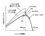
- FIG. 12A is a diagram illustrating a change in system output torque by assist control, in which the horizontal axis indicates the engine speed and the vertical axis indicates the output torque.
- FIG. 13A is a diagram illustrating a change in system output horsepower by assist control, in which the horizontal axis indicates the engine speed and the vertical axis indicates the output horsepower.
- FIG. 12B is a diagram illustrating changes in system output torque due to battery charge control, in which the horizontal axis indicates the engine speed and the vertical axis indicates the system output torque.
- FIG. 13B is a diagram illustrating changes in engine output horsepower due to battery charging control, in which the horizontal axis indicates the engine speed and the vertical axis indicates the engine output horsepower.
- symbol X1 indicates that the battery charge rate is 50% or more (determination in step S100 is NO), charging control is not performed, and the engine speed is higher than the rated speed NRmax (NRx) and absorption by the hydraulic pump 21
- the operating point of the engine 11 when the torque (load torque) is covered only by the output torque of the engine 11 (NO in step S160) is shown.
- the absorption torque of the hydraulic pump 21 increases from this state to the maximum absorption torque TPLc
- the operating point of the hybrid drive system that combines the engine 11 and the generator / motor 31 changes from X1 to X2 to X3 to X4.
- the fuel injection amount reaches the maximum Fmax (FIG. 3), and the output torque of the engine 11 increases to the rated torque Topt (operating point).
- X2 When the rotational speed of the engine 11 further decreases, the generator / motor 31 operates as a motor (the determination in step S160 is YES ⁇ step S140), and the engine rotational speed is controlled to be maintained at the rated rotational speed NRmax. Further, the system output torque is the sum of the rated torque Topt of the engine 11 and the output torque TM of the generator / motor 31.
- the operating points of the engine output horsepower and the system output horsepower change from X1 ⁇ X2 ⁇ X3 ⁇ X4 in response to the change in the output torque described above.
- Symbols HE1 and HS1 indicate the engine output horsepower and the system output horsepower at the operating point X1, and they coincide with each other.
- symbols HE2 and HS2 indicate the engine output horsepower and the system output horsepower at the operating points X2 and X4, respectively.
- the engine output horsepower HE2 is the maximum horsepower
- the system output horsepower HS2 is the total output of the engine output horsepower HE2 (maximum horsepower) and the output horsepower HM of the electric motor 31.
- the symbol Y1 indicates that the battery charging rate is 50% or more (determination in step S100 is NO), the charging control is not performed, and the engine speed is the rated speed NRmax (The operating point of the engine 11 when the absorption torque (load torque) of the hydraulic pump 21 is covered only by the output torque of the engine 11 (NO in step S160) is shown. If the battery charging rate becomes smaller than 50% from this state (YES in step S100), the operating point of the engine 11 changes from Y1 to Y2.
- the symbol HE3 indicates the engine output horsepower at the operating point Y1.
- the symbol HE4 indicates the engine output horsepower when the battery charging control is performed at the operating point Y2. At this time, the engine output horsepower HE4 becomes the maximum horsepower, and the difference horsepower HGn between HE3 and HE4 becomes the charging horsepower.
- the engine 11 is not large enough to cover the maximum absorption torque of the hydraulic pump 21 (more specifically, the rated torque Topt or maximum torque TEmaxw of the engine 11 is the maximum of the hydraulic pump 21. Since it is downsized to a size smaller than the absorption torque TPLc), it is possible to improve fuel consumption, improve exhaust gas characteristics, and reduce noise. In addition, even a small construction machine such as a mini excavator can secure the installation space for the battery 33, and the hybrid system can be easily adopted.
- the output of the hydraulic pump 21 at the time of normal operation C is smaller than that at the time of traveling high speed A, so that the rated torque Topt or the maximum torque TEmaxe is the hydraulic pump 21.
- the output of the hydraulic pump 21 during normal operation is often covered by an output equal to or lower than the rated torque Topt of the engine 11.
- output assist control is performed when the engine speed falls below the rated speed NRmax, and when the engine speed is greater than the rated speed NRx (the engine 11 has surplus torque).
- the frequency of the output assist control is reduced, and the power consumption of the battery 33 is suppressed.
- the charge control frequency of the battery 33 can be increased without reducing the work efficiency, and the charge amount of the battery 33 can be increased.
- the battery 33 is small enough to be mounted in a narrow space on the turning frame. Even if it is realized, an early decrease in the remaining charge of the battery 33 can be suppressed, and the frequency at which the charge rate of the battery 33 is reduced below the minimum charge rate, that is, the frequency at which quick charge is performed can be reduced.
- the frequency of interrupting work for charging the battery 33 can be reduced, the reduction in work efficiency can be suppressed, and the operating rate of the machine body can be improved.
- the assist control and the battery charge control are switched based on the magnitude determination result between the engine speed and the maximum horsepower speed NRx (or the rated speed NRmax when the target speed is the maximum NTmax).
- the maximum horsepower rotation speed NRx used for determination may have a margin. That is, a predetermined margin ⁇ N is set in consideration of engine speed hunting and the like, battery charge control is performed when the engine speed exceeds the maximum horsepower speed NRx + ⁇ N, and the engine speed is set to the maximum horsepower speed NRx ⁇ . Assist control may be performed when it becomes smaller than ⁇ N. Thereby, the control of the generator / motor 31 when the engine speed is in the vicinity of the maximum horsepower speed NRx can be stabilized.
- the present invention is not limited to this, and it is also possible to employ isochronous control that adjusts the fuel injection amount so that the engine speed is kept constant regardless of an increase in engine load.
- FIG. 14A is a diagram showing a relationship between the engine speed and the engine output torque when the isochronous control is adopted, and FIG. 14B shows a relationship between the engine speed and the engine output horsepower when the isochronous control is adopted.
- FIG. 14A is a diagram showing a relationship between the engine speed and the engine output torque when the isochronous control is adopted
- FIG. 14B shows a relationship between the engine speed and the engine output horsepower when the isochronous control is adopted.
- the present invention can be applied even when isochronous control is employed.
- the engine controller 13 has a function of calculating an engine load factor and generating engine load factor information.
- the engine load factor is obtained, for example, by calculating the ratio of the target fuel injection amount to the maximum fuel injection amount.
- the vehicle body controller 46 includes an instruction signal from the travel speed changeover switch 41, detection signals from the operation pilot pressure sensors 42 and 43, engine speed information (target speed and detected actual speed) of the engine controller 13, and storage of the battery controller 34.
- the engine load factor information generated by the engine controller 13 is input, a predetermined calculation process is performed, and a control signal is output to the inverter 32 and the travel speed switching electromagnetic valve 45.
- FIG. 15 is a flowchart showing a processing procedure related to output assist control and charge control of the vehicle body controller 46 in the present embodiment.
- the same reference numerals are given to the same processes as those constituting the flow shown in FIG. In the following, the description will focus on the parts that are different from the flow shown in FIG.
- step S110 If NO (engine speed ⁇ maximum horsepower speed NRx) is determined in step S110, the engine load factor change rate is obtained by differentiating the engine load factor acquired from the engine load factor information from the engine controller 13. An engine load change rate is calculated, and it is determined whether or not the engine load change rate is greater than a predetermined threshold (step S111).
- the predetermined threshold is a threshold for determining whether or not a sudden load is applied to the engine 11.
- step S111 when it is determined as YES (engine load change rate> threshold) in step S111, it is a case where a sudden load is applied to the engine 11, and the output / motor 31 is actuated as an electric motor for early output assist control ( Second output assist control) is performed (step S140), and the process is terminated.
- Second output assist control Second output assist control
- step S160 engine speed ⁇ maximum horsepower speed NRx
- step S161 it is determined whether the engine load change rate is larger than a predetermined threshold as in step S111 (step S161). If YES (engine load factor deviation> threshold value) is determined in step S161, this is a case where a sudden load is applied to the engine 11, and the power generation / motor 31 is operated as an electric motor so that early output assist control (second Output assist control) is performed (step S140), and the process is terminated. On the other hand, if NO (engine load change rate ⁇ threshold) is determined in step S161, the process ends.
- FIG. 16A is a diagram showing changes in engine speed and system output torque when a sudden load is applied in the present embodiment
- FIG. 16B shows engine speed and system output horsepower when a sudden load is applied in the present embodiment. It is a figure which shows the change of.
- FIG. 16A consider the case where the operating point changes from X1 to X4, as in FIG. 12A in the first embodiment.
- the operating point of the hybrid drive system combining the engine 11 and the generator / motor 31 is X1 ⁇ X2 ⁇ X3A ⁇ X4.
- the engine speed is greatly reduced due to the delay of the output assist control (the operating point X3A), and then the generator / motor 31 starts to operate and the engine rotation
- the number is controlled to increase and return to the rated rotational speed NRmax (operating point X4).
- the operating point of the hybrid drive system that combines the engine 11 and the generator / motor 31 is X1 ⁇ X2 ⁇ X3B ⁇ X4.
- the second output assist control is started immediately after the sudden load is applied (NO in step S160, YES in step 161, YES in step S140).
- a decrease in the engine speed until the generator / motor 31 starts to operate is suppressed to a small level (operation point X3B), and then the engine speed increases to the rated speed. Control is made to return to NRmax (operation point X4).
- the same effect as in the first example can be obtained.
- the amount of decrease in the rotational speed when the engine rotational speed falls below the rated rotational speed NRmax is reduced, and the actuator speed A decrease in work efficiency due to a decrease in (work speed) can be prevented.
- the switching between the first output assist control and the first charging control is performed, even if the work machine is a small work machine such as a mini excavator and the battery 33 is downsized, the battery An early decrease in the remaining charge amount of 33 can be suppressed.
- a small hydraulic excavator it is difficult to recover the power consumption of the battery 33 by the regenerative energy at the time of turning braking when the turning electric motor is used. Therefore, the charging control of the battery 33 is efficiently performed as described above. However, it is unavoidable that the amount of charge of the battery falls below the minimum charging rate, and it is necessary to consider measures in that case.
- FIG. 17 is a diagram showing a hybrid drive system of a hydraulic excavator in the present embodiment.
- the control system 4A of the hybrid drive system in the present embodiment further includes a torque control electromagnetic valve 44, and the vehicle body controller 46A is also electrically connected to the torque control electromagnetic valve 44, and a control signal is sent to the torque control electromagnetic valve 44. Is output.
- the torque control solenoid valve 44 adjusts the maximum absorption torque of the hydraulic pump 21 by outputting a control pressure to the pump regulator 27A based on the control signal.
- FIG. 18 is a diagram showing details of the configuration of the pump regulator 27A.
- the pump regulator 27A has first and second pressure receiving portions 27d and 27e that act in the capacity decreasing direction of the hydraulic pump 21 with respect to the control spool 27a.
- the discharge pressure of the hydraulic pump 21 is introduced to the first pressure receiving portion 27d via the pilot line 27f, and the control pressure from the torque control electromagnetic valve 44 is introduced to the second pressure receiving portion 27e via the control oil passage 27g. .
- the torque control solenoid valve 44 When the control signal is not output from the vehicle body controller 46A, the torque control solenoid valve 44 is in the illustrated OFF position, and connects the second pressure receiving portion 27e of the pump regulator 27A to the tank.
- the torque control electromagnetic valve 44 When the control signal is output from the vehicle body controller 46A, the torque control electromagnetic valve 44 is switched to the ON position, and the discharge pressure of the pilot pump 22 is guided to the second pressure receiving portion 27e as the control pressure.
- the discharge pressure of the pilot pump 22 is maintained at a constant value (for example, 4 Mpa) by the pilot relief valve 28.
- FIG. 19 is a pump torque characteristic diagram by torque control of the pump regulator 27A, the horizontal axis indicates the discharge pressure of the hydraulic pump 21, and the vertical axis indicates the capacity of the hydraulic pump 21.
- the torque control electromagnetic valve 44 When the torque control electromagnetic valve 44 is in the OFF position shown in FIG. 18, the second pressure receiving portion 27e of the pump regulator 27A communicates with the tank, and the maximum absorption torque characteristic is indicated by a solid line by the first and second springs 27b and 27c. It is set like a bent line composed of the straight lines TP1 and TP2. The torque control at this time is the same as that of the pump regulator 27 shown in FIG.
- the control pressure is guided to the second pressure receiving portion 27e, and the oil pressure of the second pressure receiving portion 27e is applied to the control spool 27a by the first and second springs 27b and 27c. Acts against power. Accordingly, the setting of the maximum absorption torque by the first and second springs 27b and 27c is adjusted so as to decrease by the amount of the oil pressure of the second pressure receiving portion 27e, and the maximum absorption torque characteristic is indicated by a solid line as indicated by an arrow.
- the bending line formed of straight lines TP1 and TP2 shifts to the bending line formed of alternate long and short dashed lines TP3 and TP4 (amount of torque reduction ⁇ TPd1).
- FIG. 20 is a flowchart showing the control function of the vehicle body controller 46A in the present embodiment. The same steps as those in the steps shown in FIG.
- step S90 to step S160 are substantially the same as step S90 to step S160 shown in FIG.
- step S140 in FIG. 10 is divided into two procedures of step S140A and step S140B, step S140A is returned to step S90, and step S140B is changed to return to step S100.
- the charging rate of the battery 33 acquired from the storage information from the battery controller 34 is larger than the minimum charging rate (SOC) (step S90).
- the minimum charging rate is a charging rate (for example, 30%) at which the continuation of work by assist driving of the generator / motor 31 becomes impossible. If YES in step 90 (battery charge rate> 30%), it is determined whether the battery charge rate is smaller than a first threshold (for example, 50%), and if the battery charge rate is smaller than the first threshold.
- a first threshold for example, 50%
- the battery charge rate is smaller than the first threshold.
- charge control first charge control
- output assist control first output assist control
- step S140A When the battery charge rate becomes larger than the second threshold (for example, 70%) by the charge control, the charge control is terminated and the process returns to step S100. If the output assist control is performed in step S140A, the process returns to step S90, and if the battery charge rate does not fall below the minimum charge rate (for example, 30%), the first output assist control (step S140A) or the first charge described above. The control (steps S120 and S130) is repeated. On the other hand, if the battery charging rate is greater than or equal to the first threshold value (for example, 50%) in step S100, the first output assist control is performed if the current engine speed (actual speed) is smaller than the maximum horsepower speed NRx.
- the first threshold value for example, 50%
- Step S160 ⁇ S140B
- the process returns to Step S100, and the first output assist control (Steps S140A, S130B) or the first charge control (Steps S120, S130) described above is repeated.
- step S90 when the charging rate of the battery 33 becomes equal to or less than the minimum charging rate (for example, 30%), the process proceeds to step S210.
- Step S210 and subsequent steps are processing procedures for rapid charge control. After performing engine speed reduction control (step S210) and pump torque reduction control (step S220), charge control (second charge control) of the battery 33 (step S230). , S240).
- control is performed to reduce the maximum target speed of the engine 11 from NTmax to Ntc.
- the vehicle body controller 46A stores in advance a target rotational speed NTc for engine rotational speed reduction control, and outputs the target rotational speed NTc to the engine controller 13.
- the engine controller 13 selects a target rotational speed NTx indicated by the engine control dial 12 and a smaller one of the target rotational speed NTc and sets it as the target rotational speed of the fuel injection control, and the fuel injection amount based on the target rotational speed.
- the electronic governor 14 is controlled.
- the maximum target rotational speed of the engine 11 decreases from NTmax to Ntc, and the output torque at the maximum horsepower rotational speed of the engine 11 increases from Topt to Topt1 (FIG. 22).
- the target rotational speed NTx indicated by the engine control dial 12 may be input on the vehicle body controller 46A side, and the maximum target rotational speed may be changed by the vehicle body controller 46A.
- the vehicle body controller 46A In the pump torque reduction control in step S220, the vehicle body controller 46A outputs a control signal to the torque control solenoid valve 44 to perform control to reduce the maximum absorption torque of the hydraulic pump 21 from TPLc to TPLd1 (FIG. 19).
- the generator / motor 31 is operated as a generator using the surplus torque of the engine 11 forcibly generated by the above engine speed reduction control and pump reduction torque control, and the battery 33 Charge the battery.
- steps S210 to S240 when the charging rate of the battery 33 (power storage device) falls below the minimum charging rate at which the operation by the assist drive of the generator / motor 31 cannot be continued, the target engine speed of the engine 11 is reduced.
- the engine 11 is forced to generate surplus torque by performing the engine speed reduction control for reducing the engine speed and the torque reduction control for reducing the maximum absorption torque of the hydraulic pump 21.
- the surplus torque is used to generate the generator / motor 31.
- the second charging control is performed to charge the battery 33 by operating as a generator.
- step S250 it is determined whether the charging rate of the battery 33 is greater than a preset third threshold value (step S250).
- the third threshold value is a charging rate indicating that the charge amount of the battery 33 has escaped from an extremely insufficient state, and is set to a value (for example, 40%) higher than the minimum charging rate (for example, 30%). Yes. If NO (battery charge rate ⁇ third threshold (40%)) is determined in step S250, the processes in steps S210 to S240 are repeatedly executed until the battery charge rate becomes equal to or higher than the third threshold. Steps S210 to S250 are compulsory battery charge control (rapid charge control) executed when the amount of charge of the battery 33 is extremely insufficient.
- step S250 battery charge rate> third threshold (40%)
- the process proceeds to step S100, and the above-described output assist control (steps S140A and S130B) or charge control (steps S120 and S130) described above. I do.
- the operations during the first output assist control and the first charge control when the charging rate of the battery 33 is greater than the minimum charging rate (SOC) are the same as those in the first embodiment described with reference to FIGS. 12A to 13B. This is the same as the operation, and the description is omitted.
- FIG. 21A is a diagram showing a change (amount of torque reduction) in the maximum absorption torque of the hydraulic pump 21 when the quick charge control is performed only by the pump torque reduction control as a comparative example, and FIG. 21B is only the pump torque reduction control.
- FIG. 6 is a diagram showing a reduction torque amount when performing quick charge control, surplus torque of engine 11 used as power generation torque for rapid charge of battery 33 at that time, and distribution of maximum torque usable for work.
- the maximum absorption torque of the hydraulic pump 21 is reduced from TPLc to TPLd2 by outputting a control signal to the torque control electromagnetic valve 44, and the amount of torque reduction at this time is ⁇ TPd2 indicated by a thick arrow.
- TG indicates the surplus torque of the engine 11 that is used as the power generation torque for the quick charge of the battery 33
- TPa indicates the maximum amount of torque that can be used for work when the engine speed reduction control is not performed.
- the maximum target speed remains NRmax.
- the maximum horsepower rotation speed (rated rotation speed) of the engine 11 is NRmax, and the output torque of the engine 11 at that time is Top.
- the maximum absorption torque TPLd2 after the torque reduction control needs to be matched with the torque amount obtained by subtracting the surplus torque TG used as the power generation torque from the output torque Topt of the engine 11, and the maximum absorption torque TPLd2 (TPa obtained by subtracting TG from Topt). ) Is the maximum amount of torque that can be used for work.
- FIG. 22A is a diagram showing a change in the maximum absorption torque (amount of torque reduction) of the hydraulic pump 21 when the quick charge control is performed by the engine speed reduction control and the pump reduction torque control in the present embodiment. It is the figure which added the output torque Topt1 in the maximum horsepower rotation speed after the engine rotation speed fall control of the engine 11.
- FIG. 22B is a diagram showing the amount of torque reduction required in the present embodiment, the surplus torque of the engine 11 at that time, and the distribution of the maximum torque that can be used for work.
- the maximum target speed decreases to NTc, and the output torque at the maximum horsepower speed of the engine 11 increases from Topt to Top1.
- the maximum absorption torque TPLd1 after the torque reduction control may be adjusted to the amount of torque obtained by subtracting the surplus torque TG used as the power generation torque from the increased output torque Top1 of the engine 11, and the maximum absorption torque TPLd1 (Top1 to TG TPb) obtained by subtracting is the maximum amount of torque that can be used for work.
- This maximum working torque amount TPb (maximum absorption torque TPLd1 after torque reduction control) is increased by the amount that the output torque at the maximum horsepower rotation speed of the engine 11 is increased from Topt to Topt1.
- the reduction torque amount ⁇ TPd2 that is the reduction amount of the maximum absorption torque is increased. Therefore, during the quick charge, the output of the hydraulic pump is greatly reduced. There is a risk of hindering work requiring high load torque such as excavation work.
- the engine output torque is increased from Topt to Top1 by the engine speed reduction control, and the decrease torque amount ⁇ TPd1 is reduced accordingly, so the reduction amount of the maximum absorption torque of the hydraulic pump 21 is compared.
- the working torque amount TPb becomes smaller than that of the comparative example, and the work amount when the work is performed during the quick charging can be suppressed.
- the engine speed reduction control for reducing the engine speed is performed, whereby the full load characteristic portion Tf1 of the engine 11 is controlled.
- the engine output torque Topt1 at the maximum horsepower rotation speed NRc increases.
- the amount of decrease in the maximum absorption torque of the hydraulic pump 21 due to the torque reduction control is suppressed as compared with the case where surplus torque is generated by performing only the torque reduction control, and the output reduction of the hydraulic pump 21 (the amount of work of the hydraulic excavator is reduced).
- the battery 33 can be rapidly charged while suppressing (decrease). As a result, it is possible to perform a certain amount of work even while the battery 33 is being charged, and it is possible to suppress a decrease in the operating efficiency of the machine body.
Abstract
ミニショベルのような小型の建設機械において、ハイブリッド方式を採用してエンジンを小型化することにより燃費の向上、排ガス特性の改善及び騒音の低減を図るとともに、蓄電装置の設置スペースを確保し、かつ蓄電装置が小型であっても蓄電装置の充電残量の早期の減少が抑えられ、蓄電装置の充電のために作業を中断する頻度を低減することにより機体の稼動率を向上できるようにする。車体コントローラ(46)は、エンジン回転数検出装置(15)で検出されたエンジン回転数がエンジン(11)の出力馬力が最大となる定格回転数以下に低下したときに、発電・電動機(31)を電動機として作動させてアシスト制御を行い、エンジン回転数が定格回転数より大きいときはバッテリ(33)の充電制御を行う。
Description
本発明は、ハイブリッド式作業機械に係わり、特に小型の油圧ショベル等のハイブリッド式作業機械に関する。
近年、油圧ショベル等の作業機械においては、燃費の向上、排ガス特性の改善及び騒音の低減等の観点から、エンジン(ディーゼルエンジン)と電動機を併用するハイブリッド式作業機械が開発され、一部実用化されている。このようなハイブリッド式作業機械として例えば特許文献1~5に記載のものがある。
特許文献1~5に記載のハイブリッド式作業機械では、主として建設機械の代表例である油圧ショベルにおいて、エンジンによって駆動される油圧ポンプの補助動力源として発電・電動機を設け、バッテリの電力で発電・電動機を電動機として駆動し、エンジンが最適トルクに対応した回転数で運転されるように出力アシストとバッテリ(蓄電装置)充電制御を行っている。
より具体的には、特許文献1及び2においては、最小燃費となる最適トルク点の燃料噴射量或いはエンジン回転数を目標燃料噴射量(特許文献1)或いは目標回転数(特許文献2)として設定し、エンジンガバナの燃料噴射量が目標燃料噴射量より大きくなる(特許文献1)、或いはエンジン回転数が目標回転数より小さくなる(特許文献2)と発電・電動機を電動機として駆動し、出力アシストを行い、エンジンガバナの燃料噴射量が目標燃料噴射量より小さくなる(特許文献1)、或いはエンジン回転数が目標回転数より大きくなる(特許文献2)と発電・電動機を発電機として駆動し、バッテリの充電制御を行っている。
特許文献3及び4においては、エンジンの平均出力時のエンジン回転数(特許文献3)或いは予め設定される回転数(特許文献4)を基準として設定し、エンジン回転数が当該回転数より小さくなると発電・電動機を電動機として駆動し、出力アシストを行い、エンジン回転数が当該回転数より大きくなると発電・電動機を発電機として駆動し、バッテリの充電制御を行っている。
特許文献5においては、エンジンの定格トルクを基準として設定し、エンジンが駆動する油圧ポンプの吸収トルクが定格トルクよりも大きくなると発電・電動機を電動機として駆動し、出力アシストを行い、油圧ポンプの吸収トルクが定格トルクよりも小さくなると発電・電動機を発電機として駆動し、バッテリの充電制御行っている。
また、特許文献3及び5には、ブーム下げ時又は旋回制動時の回生エネルギーによって電動機を発電機として駆動して発電し、発電した電力をバッテリに蓄電することにより、バッテリの充電状態を回復する方法が記載されている。特許文献5においては、これによりエンジンの平均必要馬力を下げ、エンジンの小型化が可能であるとしている。
特許文献1及び2に記載のハイブリッド式建設機械では、エンジン回転数が常に最小燃費が得られるトルクに対応した回転数と一致するように電動機で出力アシストを行うため、出力アシストの頻度が高くバッテリの消費電力が大きい。また、特許文献3に記載のハイブリッド建設機械では、エンジン回転数が常に平均出力時の回転数と一致するように電動機で出力アシストを行うため、こちらも出力アシストの頻度が高くバッテリの消費電力が大きい。特許文献4に記載のハイブリッド式建設機械においても、エンジン回転数が常予め設定される回転数よりも低下すると電動機で出力アシストを行うため、出力アシストの頻度が高くバッテリの消費電力が大きい。このためエンジンとバッテリの両方を小型化することは難しく、これらの技術を小型油圧ショベルに適用することはできなかった。
特許文献5に記載のハイブリッド式建設機械においては、ブーム下げ時又は旋回制動時の回生エネルギーによって電動機を発電機として駆動して発電し、発電した電力をバッテリに蓄電しながら、エンジンが駆動する油圧ポンプの吸収トルクと定格トルクとを比較して油圧ポンプの吸収トルクが定格トルクよりも大きくなったときに電動機で出力アシストを行っている。しかし、ブーム下げ時或いは旋回動作時の慣性エネルギーが非常に小さいミニショベルのような小型の建設機械においては、ブーム下げ時或いは旋回制動時の回生エネルギーによってバッテリの消費電力を回収することは困難である。また、出力アシストを行う状態にあるかどうかを判断する指標として油圧ポンプの吸収トルクを用いているが、油圧ポンプの吸収トルクの正確な取得は難しいばかりでなく、比較対象である実際の定格トルクは標高(気圧)などの環境により変化するため、出力アシストが必要な状態にあるかどうかを正確に判断することはできない。
ここで、ミニショベルのような小型の建設機械では、中型及び大型な建設機械に比べて、旋回フレーム上のスペースが狭いため、中型及び大型な建設機械でみられるようなハイブリット方式を採用することが、レイアイト面で非常に困難である。このためエンジンばかりでなくバッテリ(蓄電装置)も極力小型化することが望まれる。このためこのような小型の油圧ショベルに特許文献5の技術を適用した場合は、バッテリの充電残量が早期に限界値まで減少し、バッテリの充電のために作業を中断する頻度が高くなり、機体の稼働率が低減してしまう。
本発明は、上記の問題に鑑みてなされたものであり、その目的は、ミニショベルのような小型の建設機械において、ハイブリッド方式を採用してエンジンを小型化することにより燃費の向上、排ガス特性の改善及び騒音の低減を図るとともに、蓄電装置の設置スペースを確保し、かつ蓄電装置が小型であっても蓄電装置の充電残量の早期の減少が抑えられ、蓄電装置の充電のために作業を中断する頻度を低減することにより機体の稼動率を向上できるハイブリッド式作業機械を提供することである。
上記目的を達成するために、本発明は、エンジンと、このエンジンによって駆動される油圧ポンプと、この油圧ポンプから吐出される圧油によって駆動される複数の油圧アクチュエータと、前記エンジンの目標回転数を指示するエンジン回転数指示装置と、前記エンジンの実回転数を検出するエンジン回転数検出装置と、前記目標回転数と前記実回転数との偏差が増大するにしたがって増大するよう前記エンジンの燃料噴射量を調整するガバナ装置とを備え、前記ガバナ装置は、前記目標回転数と前記実回転数との偏差が増大するにしたがって前記燃料噴射量を増大させることで、前記エンジンの負荷トルクが増加するにしたがって前記エンジンの出力トルクが増加するよう制御するハイブリッド式作業機械において、前記エンジンに連結された発電・電動機と、前記発電・電動機との間で電力を授受する蓄電装置と、前記エンジン回転数指示装置が指示する目標回転数が最大であるときに前記エンジンの出力馬力が最大となるエンジン回転数を定格回転数として予め設定しておき、前記エンジン回転数検出装置によって検出されたエンジン回転数が前記定格回転数以下に低下したときに、前記エンジン回転数が前記定格回転数に維持されるよう前記発電・電動機を電動機として作動させ、前記油圧ポンプをアシスト駆動するよう制御する第1出力アシスト制御を行い、前記エンジン回転数が前記定格回転数以下に低下していないときは、前記エンジンの余剰トルクによって前記発電・電動機を発電機として作動させ、前記蓄電装置を充電する第1充電制御を行う制御装置とを備えたものとする。
このように構成した本発明においては、ハイブリッド方式を採用してエンジンをダウンサイジング(小型化)することにより(特に、エンジンの最大トルクが油圧ポンプの最大吸収トルクよりも小さく、エンジンの出力トルクだけでは油圧ポンプの最大吸収トルクを賄えない大きさにエンジンをダウンサイジングすることにより)、燃費の向上、排ガス特性の改善及び騒音の低減を図ることができる。また、ミニショベルのような小型の作業機械であっても蓄電装置の設置スペースを確保することができる。
また、ミニショベルのような小型の油圧ショベルにおいては、通常作業時の油圧ポンプ21の出力が走行高速時よりも小さいため、ダウンサイジングしたエンジンであっても通常作業時の油圧ポンプの出力をエンジンの定格トルク以下の出力で賄える場合が多い。このような小型の油圧ショベルにおいて、エンジン回転数が定格回転数以下に低下したときに出力アシスト制御を行い、エンジン回転数が定格回転数より大きい(エンジンに余剰トルクがある)ときに充電制御を行うことにより、出力アシスト制御の頻度が少なくなり、バッテリの消費電力が抑えられる。また、作業効率を低下させることなくバッテリの充電制御の頻度を増加させ、バッテリの充電量を増加させることができる。これによりブーム下げ時或いは旋回制動時の回生エネルギーによってバッテリの消費電力を回収することができないミニショベルのような小型の建設機械において、旋回フレーム上の狭いスペースに搭載可能なサイズにバッテリが小型化されていても、バッテリの充電残量の早期の減少が抑えられ、蓄電装置の充電のために作業を中断する頻度を低減することにより機体の稼動率を向上できる。
また、定格回転数を基準として出力アシスト制御と充電制御の切り換えを行うため、定格トルクを基準として出力アシスト制御と充電制御を切り換える場合のようなトルク情報取得の困難性や環境変化の影響の問題は無く、出力アシストが必要な状態にあるかどうかを正確に判断することができる。このため出力アシスト制御と充電制御の切り換えを的確に精度良く行うことができ、出力アシスト制御と充電制御の切り換えの不正確さに伴うバッテリ消費量の増加を低減することができ、機体の稼動効率を向上することができる。
本発明によれば、ミニショベルのような小型の建設機械であっても、ハイブリッド方式を採用してエンジンをダウンサイジング(小型化)することにより、燃費の向上、排ガス特性の改善及び騒音の低減を図るとともに、ハイブリッド方式の採用に必須である蓄電装置の設置スペースを確保することができる。また、出力アシスト制御の頻度を少なくし、充電制御の頻度を増加させ、蓄電装置の消費電力を抑えることにより、小型の建設機械の狭いスペースに搭載可能なサイズに蓄電装置を小型化しても充電残量の早期の減少が抑えられ、蓄電装置の充電のために作業を中断する頻度を低減することにより機体の稼動率を向上できる。
以下、本発明の実施の形態を図面を用いて説明する。
~構成~
図1は、本発明の第1の実施の形態に係るハイブリッド式作業機械である小型の油圧ショベルの外観を示す図である。本明細書において、小型の油圧ショベルとはミニショベルを含む8トンクラス以下の油圧ショベルを意味する。
図1は、本発明の第1の実施の形態に係るハイブリッド式作業機械である小型の油圧ショベルの外観を示す図である。本明細書において、小型の油圧ショベルとはミニショベルを含む8トンクラス以下の油圧ショベルを意味する。
油圧ショベルは、下部走行体101と、この下部走行体101上に旋回可能に搭載された上部旋回体102と、この上部旋回体102の先端部分にスイングポスト103を介して上下及び左右方向に回動可能に連結されたフロント作業機104とを備えている。下部走行体101はクローラ方式であり、トラックフレーム105の前方側に上下動可能な排土用のブレード106が設けられている。上部旋回体102は基礎下部構造をなす旋回台107と、旋回台107上に設けられたキャビン(運転室)108とを備えている。フロント作業機104はブーム111と、アーム112と、バケット113とを備え、ブーム111の基端はスイングポスト103にピン結合され、ブーム111の先端はアーム112の基端にピン結合され、アーム112の先端はバケット113にピン結合されている。
上部旋回体102は下部走行体101に対して図示しない旋回モータにより旋回駆動され、スイングポスト103及びフロント作業機104は旋回台107に対してスイングシリンダ24gにより左右に回動駆動され、ブーム111、アーム112、バケット113は、それぞれ、ブームシリンダ24c、アームシリンダ24d、バケットシリンダ24eを伸縮することにより上下に回動駆動される。下部走行体101は左右の走行モータ24a,24bにより回転駆動され、ブレード106はブレードシリンダ24hにより上下に駆動される。
図2は、図1に示した油圧ショベルのハイブリッド駆動システムを示す図である。図2において、ハイブリッド駆動システムは、エンジン系1と、油圧系2と、発電電動系3と、制御系4とを備えている。
エンジン系1は、ディーゼルエンジン11と、エンジンコントロールダイヤル12と、エンジンコントローラ13と、電子ガバナ14と、エンジン回転数検出装置15とを備えている。ディーゼルエンジン11は、後述する如く、従来のものよりもダウンサイジングした(エンジン出力の小さい)エンジンである。
エンジンコントロールダイヤル12は、オペレータの操作によりエンジン11の目標回転数を指示するものである。目標回転数とは、エンジン11に負荷が投入されていないときのエンジン回転数である。エンジンコントローラ13は、エンジンコントロールダイヤル12からの目標回転数信号を入力し、所定の演算処理を行って目標燃料噴射量を求め、電子ガバナ14を制御することによりエンジンの各気筒に噴射される燃料噴射量を制御し、エンジン出力トルクとエンジン回転数を制御する。なお、本実施の形態では、電子ガバナ14の制御に、エンジン負荷の増加に応じてエンジン回転数を低下させつつ燃料噴射量を増加させるドループ制御を採用した場合を例に説明する。エンジン回転数検出装置15は、エンジン11の実回転数を検出するものである。エンジン回転数検出装置15によって検出されたエンジン回転数は、エンジンコントローラ13を介して車体コントローラ46(後述)に入力される。
図3は、エンジンコントローラ13が燃料噴射量を演算するときに用いる燃料噴射量特性を示す図である。図中、横軸はエンジンコントロールダイヤル12が指示する目標回転数とエンジン回転数検出装置15によって検出されたエンジン11の実回転数との偏差ΔNであり、縦軸は燃料噴射量Fである。この燃料噴射量特性は、回転数偏差ΔNがゼロであるとき、燃料噴射量Fは最小Fminであり、回転数偏差ΔNが増大するにしたがって燃料噴射量Fは斜めの直線F1の特性に沿って直線比例的に増大するよう設定されている。また、回転数偏差ΔNがある所定の値ΔNaに達すると、燃料噴射量Fは最大Fmaxとなり、それ以上回転数偏差ΔNが増大したときは、燃料噴射量Fは最大Fmaxの一定値に保持される。通常のエンジン制御では、目標回転数毎に燃料噴射量特性を記憶しておき、エンジンコントロールダイヤル12が指示する目標回転数に応じて対応する燃料噴射量特性を選択し、そのとき演算した回転数偏差ΔNを燃料噴射量特性に参照して対応する燃料噴射量を求め、その燃料噴射量を目標値として電子ガバナ14に与え、エンジン11の各気筒に噴射される燃料噴射量を制御する。
図4は、そのように燃料噴射量が制御されたときのエンジン11の出力トルク特性を示す図であり、エンジンコントロールダイヤル12が指示する目標回転数が最大であるときのものである。図中、横軸はエンジン回転数であり、縦軸はエンジン出力トルクである。エンジン11の出力トルク特性は、燃料噴射量が最大であるときの全負荷特性Tfと、図3に示した燃料噴射特性に基づいて燃料噴射量が調整されるレギュレーション特性Tgmaxとからなっている。全負荷特性Tfはエンジン11の特性によって定まるものであり、エンジン回転数が低下するにしたがってエンジン11の出力トルクが最大TEmaxeまで増加する左上がりの特性部分Tf1と、エンジン回転数が更に低下するにしたがってエンジン11の出力トルクが減少する左下がりの特性部分Tf2とからなっている。レギュレーション特性Tgmaxは、図3に示した燃料噴射特性に対応して、エンジン回転数が低下するにしたがってエンジン11の出力トルクが増大するドループ制御の特性となっている。
すなわち、エンジン11に負荷が投入されていないときは燃料噴射量は最小Fminであり、このときのエンジン回転数はレギュレーション特性Tgmaxの直線と横軸との交点のNTmaxである。エンジン11の負荷トルク(油圧ポンプ21の吸収トルク)が増大し、目標回転数NTmaxと実回転数との偏差ΔNが増大するにしたがって燃料噴射量が増大し、それに伴ってエンジン11の出力トルクはレギュレーション特性Tgmaxの斜めの直線に沿って直線比例的に増大する。エンジン11の負荷トルクが更に増大し、回転数偏差ΔNが所定の値ΔNaに達すると燃料噴射量は最大となる(図3)。レギュレーション特性Tgmaxの直線と全負荷特性Tfとの交点は燃料噴射量が最大Fmaxとなり、エンジン11の出力馬力が最大となる点(後述)であり、このときの回転数(最大馬力回転数)NRmaxが定格回転数であり、エンジン11の出力トルクToptが定格トルクである。
エンジンコントロールダイヤル12が最大目標回転数NTmaxよりも低い目標回転数NTx1,NTx2を指示するとき、エンジンコントローラ13は目標回転数NTx1,NTx2のそれぞれに対応した燃料噴射特性を選択して燃料噴射量を制御し、それに対応してレギュレーション特性は破線Tg1,Tg2と変化する。その結果、最大馬力回転数はNR1,NR2と低下する(後述)。
本実施の形態では、エンジンコントロールダイヤル12が指示する目標回転数がエンジン11に負荷が投入されていないときの回転数NTmax,NTx1,NTx2であると定義したが、目標回転数は最大馬力回転数(エンジンコントロールダイヤル12が指示する目標回転数が最大であるときは定格回転数)NRmax,NR1,NR2であると定義してもよい。また、本実施の形態では、レギュレーション特性がドループ制御の特性である場合について説明したが、レギュレーション特性は、エンジン負荷の増加によらずエンジン回転数が一定に保たれるように燃料噴射量を調整するアイソクロナス制御の特性であってもよい(後述)。
エンジン11の出力軸は大径ギヤ6aと小径ギヤ6bからなる動力分配機6を介して油圧系2と発電電動系3に接続されている。
油圧系2は、油圧ポンプ21及びパイロットポンプ22と、コントロールバルブ23と、複数の油圧アクチュエータ24a~24hと、複数の操作装置25,26とを備えている。
油圧ポンプ21はエンジン11の出力軸に動力分配機6を介して接続され、エンジン11により駆動される。油圧ポンプ21から吐出された圧油はコントロールバルブ23を介して複数の油圧アクチュエータ24a~24hに供給され、それぞれの被駆動体を駆動する。油圧ポンプ21は可変容量型であり、押しのけ容積可変機構(例えば斜板)21aと、押しのけ容積可変機構21aの傾転位置を調整し、油圧ポンプの容量を制御するポンプレギュレータ27を備えている。
複数の油圧アクチュエータ24a~24hは、左右の走行用油圧モータと、それ以外の油圧アクチュエータを含み、それ以外の油圧アクチュエータは、例えば、ブーム用油圧シリンダ、アーム用油圧シリンダ、バケット用油圧シリンダ、スイング用油圧シリンダ、ブレード用油圧シリンダを含む。
コントロールバルブ23は複数の油圧アクチュエータ24a~24hに対応する複数のメインスプールを内蔵し、これらメインスプールは操作装置25,26から出力される油圧信号により切換操作される。操作装置25は左右の走行用の操作装置を代表したものであり、操作装置26は走行以外の操作装置を代表したものである。
発電電動系3は、発電・電動機31と、インバータ32と、バッテリ(蓄電装置)33と、バッテリコントローラ34と、操作パネル35とを備えている。
発電・電動機31はエンジン11の出力軸に動力分配機6を介して接続され、エンジン11に余剰トルクがあるときは、その余剰トルクによって駆動されて発電機として作動する。発電・電動機31が発生した電気エネルギーはインバータ32を介してバッテリ33に蓄電される。また、発電・電動機31は、バッテリ33の容量に対する蓄電量の比率(以下、充電率という)がアシスト駆動に必要な最小充電率(例えば30%)以上でありかつ油圧ポンプ21をアシスト駆動する必要があるときは、インバータ32を介してバッテリ33の電気エネルギーが供給され、電動機として作動する。バッテリコントローラ34はバッテリ33の蓄電量を監視し、操作パネル35はその蓄電量に係わる情報(蓄電情報)を表示する。
制御系4は、走行速度切換スイッチ41と、走行速度切替電磁弁45と、制御装置としての車体コントローラ46とを備え、車体コントローラ46は、走行速度切替電磁弁45、インバータ32、バッテリコントローラ34、操作パネル35及びエンジンコントローラ13と電気的に接続されている。車体コントローラ46は、走行速度切換スイッチ41の指示信号、エンジンコントローラ13のエンジン回転数情報(目標回転数及び検出した実回転数)及びバッテリコントローラ34の蓄電情報(充電率)を入力し、所定の演算処理を行い、インバータ32及び走行速度切替電磁弁45に制御信号を出力する。
図5は、ポンプレギュレータ27の構成の詳細を示す図である。
ポンプレギュレータ27は、複数の操作装置25,26の操作量に基づく要求流量に応じた流量を吐出するよう油圧ポンプ21の押しのけ容積可変機構21aの傾転位置を制御する(したがって油圧ポンプ容量を制御する)LS制御部等の要求流量応答制御部と、油圧ポンプ21の最大吸収トルクを予め定められた値を超えないように油圧ポンプ21の押しのけ容積可変機構21aの最大傾転位置を制御する(したがって油圧ポンプの最大容量を制御する)トルク制御部とを有している。図5は、図示の簡略化のため、トルク制御部のみ図示している。また、動力分配機6は図示を省略している。
図5において、ポンプレギュレータ27は、油圧ポンプ21の押しのけ容積可変機構21aに作動的に連結された制御スプール27aと、この制御スプール27aに対して油圧ポンプ21の容量増加方向に作用する第1及び第の2つのバネ27b,27cと、制御スプール27aに対して油圧ポンプ21の容量減少方向に作用する受圧部27dとを有している。受圧部27dには油圧ポンプ21の吐出圧力がパイロットライン27fを介して導入される。第1及び第2バネ27b,27cは油圧ポンプ21の最大吸収トルクを設定するものである。第1バネ27bは第2バネ27cよりも長く、制御スプール27aが図示の初期位置にあるときは第1バネ27bのみが制御スプール27aに接触して、制御スプール27aを図示右方向に付勢する。制御スプール27aが図示左方向にある程度移動すると第2バネ27cも制御スプール27aに接触して、第1及び第2バネ27b,27cの両方が制御スプール27aを図示右方向に付勢する。
図6は、ポンプレギュレータ27のトルク制御部の機能を示すポンプトルク特性図であり、横軸は油圧ポンプ21の吐出圧力を示し、縦軸は油圧ポンプ21の容量を示している。
また、図6において、符号TP1及びTP2で示される2つの直線(実線)からなる折れ曲がり線は第1及び第2バネ27b,27cにより設定される最大吸収トルク特性である。直線TP1,TP2に接する符号TPLcで示される曲線は油圧ポンプ21の最大吸収トルクであり、これはトルク制御の制限トルクということもできる。油圧ポンプ21の最大吸収トルク(制限トルク)TPLcはエンジン11の定格トルクToptに発電・電動機31の最大トルクTMmaxを加算した定格システムトルクToptc(後述)よりも所定の余裕分だけ小さくなるように設定されている。また、油圧ポンプ21の最大吸収トルクTPLcはエンジン11の定格トルクToptより大きく、本実施の形態においては油圧ポンプ21の最大吸収トルクTPLcは更に最大トルクTEmaxe(後述)よりも大きい。
このような油圧ポンプ21の吸収トルクとエンジン11の出力トルクとの関係から分かるように、エンジン11は、定格トルクToptが油圧ポンプ21の最大吸収トルクTPLcよりも小さく、エンジン11の出力トルクだけでは油圧ポンプ21の最大吸収トルクTPLcを賄えない大きさにダウンサイジング(小型化)されている。また、本実施の形態においては、更にエンジン11は、定格トルクToptだけでなく最大トルクTEmaxeも油圧ポンプ21の最大吸収トルクTPLcよりも小さい大きさにダウンサイジングされている。なお、図中、Aは走行高速時の代表的な出力使用範囲、Bは走行低速時の代表的な出力使用範囲、Cは通常作業時の代表的な出力使用範囲を示しており、これらについては後述する。
ポンプレギュレータ27のトルク制御部は、油圧ポンプ21の吐出圧力に応じて油圧ポンプ21の押しのけ容積可変機構21aの最大傾転位置(したがって油圧ポンプ21の最大容量)を制限することで油圧ポンプ21の最大吸収トルクを制限するものである。油圧ポンプ21の吐出圧力の上昇時に吐出圧力が第1の値P1を超える前は、油圧ポンプ21の吐出圧力が導かれる受圧部27dの油圧力は第1バネ27bの付勢力より小さく、油圧ポンプ21の最大容量はqmaxに維持される。すなわち、油圧ポンプ21の容量は要求流量応答制御部の制御によりqmaxまで上昇させることができる。油圧ポンプ21の吐出圧力が更に上昇して第1の値P1を超えると、受圧部27dの油圧力は第1バネ27bの付勢力より大きくなり、制御スプール27aは図示左方向に移動して、油圧ポンプ21の最大容量は折れ曲げ線の直線TP1に沿って減少する。これにより要求流量応答制御部により制御される油圧ポンプ21の容量は直線TP1が規定する最大容量以下に制限され、油圧ポンプ21の吸収トルク(ポンプ吐出圧力と容量の積)は制限トルクTPLcを超えないように制御される。
油圧ポンプ21の吐出圧力が更に上昇して第2の値P2を超えると、制御スプール27aは第2バネ27cに接触して、油圧ポンプ21の吐出圧力の上昇量に対する制御スプール27aの移動量の割合(油圧ポンプ21の容量の減少割合)は減少し、油圧ポンプ21の最大容量は直線TP1よりも傾きの小さい直線TP2に沿って減少する。この場合も、油圧ポンプ21の吸収トルクは制限トルクTPLcを超えないように制御される。油圧ポンプ21の吐出圧力がメインリリーフ弁29の設定圧力に達すると、それ以上油圧ポンプ21の吐出圧力の上昇は阻止される。
図7は、油圧系のコントロールバルブと複数の油圧アクチュエータのうち、左右の油圧走行モータ(以下走行モータという)に係わる油圧回路部分を示す図である。図中、左右の走行用のメインスプールを符号23a,23bで示し、左右の走行モータを符号24a,24bで示している。左右の走行モータ24a,24bはメインスプール23a,23bを介して油圧ポンプ21に接続されている。
左右の走行モータ24a,24bはそれぞれ可変容量型であり、押しのけ容積可変機構(斜板)24a1,24b1と、押しのけ容積可変機構24a1,24b1をそれぞれ駆動する制御ピストン24a2,24b2とを備えている。制御ピストン24a2,24b2の一側には受圧部24a3,24b3が形成され、その反対側にはバネ24a4,24b4が配置されている。
走行速度切替電磁弁45が図示のOFF位置にあるとき、制御ピストン24a2,24b2の受圧部24a3,24b3はタンクに連通しており、制御ピストン24a2,24b2はバネ24a4,24b4の力で押されて図示の位置にあって、押しのけ容積可変機構24a1,24b1は大傾転位置(大容量位置)に保持されている。走行速度切替電磁弁45がON位置に切り換えられると、制御ピストン24a2,24b2の受圧部24a3,24b3に制御圧力としてパイロットポンプ22の吐出圧力が導かれ、これにより制御ピストン24a2,24b2が作動して、押しのけ容積可変機構24a1,24b1は大傾転位置(大容量位置)から小傾転位置(小容量位置)へと切り換えられる。大傾転位置では走行モータ24a,24bは低速回転が可能であり、走行低速に適した状態となり(低速大容量モード)、小傾転位置では走行モータ24a,24bは高速回転が可能であり、走行高速に適した状態となる(高速小容量モード)。車体コントローラ46は走行速度切換スイッチ41の指示信号を入力し、走行速度切換スイッチ41が走行低速を指示しているときは何もせず、走行速度切替電磁弁45をOFF位置に保持し、走行速度切換スイッチ41が走行高速を指示しているときは走行速度切替電磁弁45に制御信号を出力し、走行速度切替電磁弁45をON位置に切り換える。
次に、本発明の動作原理について説明する。
図8Aは、従来の一般的なミニショベルの油圧ポンプのPQ特性(馬力特性)と代表的な出力使用範囲との関係を示す図であり、横軸は油圧ポンプの吐出圧力を示し、縦軸は油圧ポンプの吐出流量を示している。図8Bは、同ミニショベルのエンジン出力馬力特性と代表的な出力使用範囲との関係を示す図であり、横軸はエンジン回転数を示し、縦軸はエンジンの出力馬力を示している。図8Cは、同ミニショベルのエンジンの出力トルク特性を示す図であり、横軸はエンジン回転数を示し、縦軸はエンジンの出力トルクを示している。図8A、図8B及び図8Cは、図4と同様、エンジンコントロールダイヤルが指示する目標回転数が最大NTmaxであるときのものである。
まず、油圧ポンプのPQ特性について説明する。油圧ポンプのPQ特性とは、ある最大吸収トルク特性を持つ油圧ポンプをエンジンで駆動して回転させ、作業を行ったときに得られる油圧ポンプの出力馬力特性である。図8Aの油圧ポンプのPQ特性は、一例として、図6に示した最大吸収トルク特性を持つ油圧ポンプ21の場合のものであり、かつエンジン回転数が定格回転数NRmaxdにある場合のものである。定格回転数NRmaxdとは、図8Cのレギュレーション特性Tgmaxdと全負荷特性Tfdの交点におけるエンジン回転数であり、図8Bに示すように、最大目標回転数NTmaxに基づいて制御されているエンジンの出力馬力が最大となるときのエンジン回転数である。
一般的なミニショベルの作業状態として、走行高速時と走行低速時と通常作業時とを考える。図8A及び図8B中、Aは走行高速時の代表的な出力使用範囲、Bは走行低速時の代表的な出力使用範囲、Cは通常作業時の代表的な出力使用範囲を示している。走行高速とは、走行モータ24a,24bが高速小容量モードにありかつ走行用の操作装置25が操作されて走行している状態をいい、走行低速とは、走行モータ24a,24bが低速大容量モードにありかつ走行用の操作装置25が操作されて走行している状態をいう。通常作業とは、走行以外の操作装置26(特にフロント作業機104に係わる油圧アクチュエータ24c,24d,24e及び旋回モータのいずれかに係わる操作装置)が操作されて作業を行っている状態をいう。
一般的なミニショベル(小型ショベル)においては、走行高速時Aはスピード(大流量)が必要であり、図8A及び図8Bに示すように走行高速時Aにおける油圧ポンプ21の出力は最も大きくなる。走行低速時B及び通常作業時Cにおいて油圧ポンプ21の出力は走行高速時Aよりも小さい。このことは、通常作業時に油圧ポンプの出力が最も大きくなる中型、大型の油圧ショベルの場合と大きな相違である。
従来のミニショベルでは、図6に示した油圧ポンプ21の最大吸収トルク(トルク制御の制限トルク)TPLcは、図8Cに示すように、エンジンの定格トルクToptdよりも所定の余裕分だけ小さく設定されている。図8Aの符号HPLcは図6及び図8Cに示した油圧ポンプ21の最大吸収トルクTPLcに対応する油圧ポンプ21の最大吸収馬力を示しており、この油圧ポンプ21の最大吸収馬力HPLcもエンジンの最大馬力(定格馬力)HEoptdよりも所定の余裕分だけ小さくなるように設定されている。また、走行高速時は油圧ポンプ21の出力は最も大きくなるため、油圧ポンプ21の最大吸収馬力HPLcは、走行高速時Aの運転状態で油圧ポンプ21に要求される油圧馬力を賄うことができる大きさに設定されている。
一方、ポンプレギュレータ27の最大吸収トルク特性(図6)は、第1及び第2の2つのバネ27b,27cによって実線の直線TP1,TP2からなる折れ曲げ線のように設定されるため、油圧ポンプ21のPQ特性も同様に符号HPで示すように折れ曲げ線形状となり、通常作業時ではエンジンの最大馬力(定格馬力)HEoptdに対して油圧ポンプ21の出力使用範囲CがPQ特性の折れ曲げ線の交点における凹み分Xa分だけXと大きく離れて、余裕がありすぎる状態となる。これは、エンジン出力馬力を有効に使用していないことを意味する。
図9Aは、本実施の形態によるミニショベルの油圧ポンプのPQ特性(馬力特性)と代表的な出力使用範囲との関係を示す図であり、図9Bは、同ミニショベルのエンジン出力馬力特性と代表的な出力使用範囲との関係を示す図である。図9Cは、エンジン11と発電・電動機31とを組み合わせたハイブリッド駆動システムの出力トルク特性を示す図である。図9A、図9B及び図9Cは、図4と同様、エンジンコントロールダイヤルが指示する目標回転数が最大でNTmaxあるときのものである。
本実施の形態では、エンジン11の最大馬力(定格馬力)HEoptを図8Bに示した従来の最大馬力(定格馬力)HEoptdよりも小さくし、油圧ポンプ21の馬力特性HPにおける最大吸収馬力HPLcを下回る設定とする。更に言えば、本実施の形態では、エンジン11の最大馬力(定格馬力)HEoptを、走行高速時A以外(走行低速時B及び通常作業時C)の運転状態で油圧ポンプ21に要求される油圧馬力の大部分を賄うことができ、走行高速時Aの運転状態で油圧ポンプ21に要求される油圧馬力を賄うことができない大きさに設定する。このことをエンジン11の出力トルクで言い換えると、エンジン11の定格トルクToptは、図6に示すように、走行高速時A以外(走行低速時B及び通常作業時C)の運転状態で油圧ポンプ21に要求される油圧トルクの大部分を賄うことができ、走行高速時Aの運転状態で油圧ポンプ21に要求される油圧トルクを賄うことができない大きさに設定されている。
本実施の形態では、このようにダウンサイジングしたエンジン11を用い、エンジン回転数が定格回転数NRmax以下に低下したときにエンジン回転数が定格回転数NRxに維持されるよう発電・電動機31を電動機として作動させ出力アシスト制御を行い、エンジン回転数が定格回転数NRxより大きい(エンジン11に余剰トルクがある)ときに発電・電動機31を発電機として作動させる充電制御(第1充電制御)を行うものである。
例えば、走行高速時Aにおいて、油圧ポンプ21の吸収トルクが最大吸収トルクTPLcまで増加し、エンジン11の回転数が定格回転数NRmaxを下回る場合には、バッテリ33により発電・電動機31を電動機として作動させ出力アシストを行う。図9CのToptcは図8Cに示す従来技術の定格トルクToptdに対応するものであり(例えばToptc=Toptd)、発電・電動機31の最大アシスト時の定格システムトルクToptc(エンジン定格トルクToptと電動機の最大トルクTMmaxの合計トルク)である。図9AのHEmaxcは、発電・電動機31の最大アシスト時のシステム出力馬力、すなわち定格システム馬力(エンジン定格馬力HEoptと電動機の最大馬力HMmaxの合計出力)である。
通常作業時Cにおいては、油圧ポンプ21の出力をエンジン11の定格トルクToptの出力で賄えない場合のみ、バッテリ33により発電・電動機31を電動機として作動させ出力アシストを行い、それ以外の場合はエンジン11の出力のみで油圧ポンプ21を駆動する。また、バッテリ33の充電残量が少ないときは充電制御(第1充電制御)によりバッテリ33に電力を充電する。
このようにエンジン11の出力トルクを従来よりも小さくし、定格トルクTopt或いは最大トルクTEmaxeが油圧ポンプ21の最大吸収トルクTPLcを下回る大きさにエンジン11をダウンサイジングしたため、低燃費化、エンジン11から排出される有害なガスの量の低減、及び騒音の低減が可能となる。また、排出ガス後処理装置の小型化或いは簡略化が可能となり、エンジン11のダウンサイジング化によるコスト低減と相まってエンジンの製作コストを低減することができ、機械全体の価格を下げることができる。また、エンジン11の最大トルクTEmaxeが油圧ポンプ21の最大吸収トルクTPLcよりも小さい大きさにまでエンジン11をダウンサイジングしたため、ミニショベルのような小型の作業機械にハイブリッド方式を採用する場合のレイアウト面の困難性を回避し、バッテリ33の設置スペースを確保することができ、ハイブリッド方式の採用が容易となる。
また、本実施の形態では、作業機械が通常作業時Cの油圧ポンプ21の出力が走行高速時Aよりも小さいミニショベルのような小型の油圧ショベルであるため、エンジン11がダウンサイジングされていても、通常作業時Cの油圧ポンプ21の出力をエンジン11の定格トルクTopt以下の出力で賄える場合が多い。このような小型の作業機械において、エンジン回転数が定格回転数NRmax以下に低下したときに出力アシスト制御を行い、エンジン回転数が定格回転数NRxより大きいときに充電制御(第1充電制御)を行うことにより、出力アシスト制御の頻度が少なくなり、バッテリ33の消費電力が抑えられる。また、バッテリ33の充電制御の頻度を増加させ、バッテリ33の充電量を増加させることができる。その結果、ブーム下げ時或いは旋回制動時の回生エネルギーによってバッテリの消費電力を回収することができないミニショベルのような小型の建設機械において、旋回フレーム上の狭いスペースに搭載可能なサイズにバッテリ33が小型化されていても、バッテリ33の充電残量の早期の減少が抑えられ、バッテリ33の充電のために作業を中断する頻度を低減することができ、機体の稼動率を向上できる。
~制御~
次に、上述した本発明の動作原理を実現する車体コントローラ46の制御機能について図10を用いて説明する。図10は、車体コントローラ46のアシスト制御及び充電制御に係わる処理手順を示すフロー図である。以下、各ステップについて順に説明する。
次に、上述した本発明の動作原理を実現する車体コントローラ46の制御機能について図10を用いて説明する。図10は、車体コントローラ46のアシスト制御及び充電制御に係わる処理手順を示すフロー図である。以下、各ステップについて順に説明する。
まず、バッテリコントローラ34からの蓄電情報から取得したバッテリ33の充電率が最小充電率(SOC)よりも大きいか否かを判定する(ステップS90)。最小充電率とは発電・電動機31のアシスト駆動による作業の継続が不能となる充電率(例えば30%)である。ステップ90でYES(バッテリ充電率>30%)と判定された場合は、バッテリ充電率が第1閾値より小さいか否かを判定する(ステップS100)。第1閾値とは、バッテリの充電量が発電・電動機31の駆動は可能であるが、バッテリ充電制御により充電を行うことが必要な状態であるか否かを判定するための閾値であり、作業の継続が不能となる最小充電率(例えば30%)よりも高い値(例えば50%)に設定されている。ステップS100でYES(バッテリ充電率<50%)と判定された場合は、エンジンコントローラ13からのエンジン回転数情報から取得した現在のエンジン回転数(実回転数)が最大馬力回転数NRxより小さいか否かを判定する(ステップS110)。前述したように、エンジンコントロールダイヤル12が指示する目標回転数が最大NTmaxであるとき、最大馬力回転数は定格回転数NRmaxある。
ここで、最大馬力回転数について、図11を用いて詳しく説明する。図11は、目標回転数とエンジン出力馬力及び最大馬力回転数の関係を示す図である。図中の実線Emax,E1,E2及び破線Smax,S1,S2は、それぞれ目標回転数をNTmax,NT1,NT2に設定した場合のエンジン馬力特性及びシステム馬力特性を示している。目標回転数NTmax,NT1,NT2(以下、NTxという)に基づいて制御されているエンジン11の出力馬力は、それぞれ、エンジン回転数が最大馬力回転数NRmax,NR1,NR1(以下、NRxという)のときに最大となる。なお、最大目標回転数NTmaxに対応する最大馬力回転数NRmaxは、エンジン11の定格回転数と一致する。図11に示した目標回転数NTxと最大馬力回転数NRxとの対応関係を車体コントローラ46の記憶装置に予め記憶させておくことにより、エンジンコントロールダイヤル12による目標回転数の設定に応じて最大馬力回転数を変更することが可能となる。
図10に戻り、ステップS110でYES(エンジン回転数<最大馬力回転数NRx)と判定された場合は、発電・電動機31を電動機として作動させ(ステップS140)、処理を終了する。ステップS140で行われる出力アシスト制御によって、エンジン回転数は上昇して最大馬力回転数NRxに戻され、最大馬力回転数NRxに維持される。また、ハイブリッド駆動システムの出力トルクは従来と同じTPLcまで増加し(図9C参照)、システム出力馬力は従来と同じHPLcまで増加する。発電・電動機31を電動機として作動させる制御方法としては、例えば最大馬力回転数からエンジン回転数(実回転数)を差し引いた回転数偏差ΔNdを求め、この回転数偏差ΔNdが大きくなるにしたがって駆動トルクが増加するよう発電・電動機31を制御すればよい。
ステップS110でNO(エンジン回転数≧最大馬力回転数NRx)と判定された場合は、エンジン11の負荷トルク(油圧ポンプ21の吸収トルク)がエンジン11の定格トルクToptよりも小さく、エンジン11に余裕がある場合であり、この場合はエンジン11の余剰トルクによって発電・電動機31を駆動して発電・電動機31を発電機として作動させ(ステップS120)、バッテリ充電制御を行う(ステップS130)。これによりエンジン11の出力トルクは定格トルクToptまで増加し、エンジン回転数は最大馬力回転数NRxまで低下し、エンジン出力馬力は最大馬力まで増加する。さらに、エンジン11の余剰トルクによって発電機31が駆動され、発電機31で発電した電力がインバータ32を介してバッテリ33に蓄電される。発電・電動機31を発電機として作動させる制御方法としては、例えばエンジン回転数(実回転数)から最大馬力回転数を差し引いた回転数偏差ΔNcを求め、この回転数偏差ΔNcが大きくなるにしたがって発電トルクが増加するよう発電・電動機31を制御すればよい。
ステップS130に続いて、バッテリ充電率が第2閾値より大きいか否かを判定する(ステップS150)。第2閾値とは、バッテリの充電が不要か否かを判定するための閾値であり、第1閾値よりも高い値(例えば70%)に設定されている。ステップS150でYES(バッテリ充電率>70%)と判定された場合は、処理を終了する。一方、ステップS150でNO(バッテリ充電率≦70%)と判定された場合は、ステップS110に戻り、ステップS110以降の処理を繰り返し実行する。
ステップS100でNO(バッテリ充電率≦50%)と判定された場合は、バッテリ33の充電が不要であるとみなせる場合であり、この場合は、ステップS110と同様にエンジン回転数が最大馬力回転数NRxより低いか否かを判定する(ステップS160)。ステップS160でYES(エンジン回転数<最大馬力回転数NRx)と判定された場合は、発電・電動機31を電動機として作動させ(ステップS140)、処理を終了する。これにより、エンジン回転数は最大馬力回転数NRxに維持されるとともに、システム出力トルクは従来と同じTPLcまで増加し(図9C参照)、システム出力馬力は従来と同じHPLcまで増加する。一方、ステップS160でNO(エンジン回転数≧最大馬力回転数NRx)と判定された場合は、処理を終了する。
また、ステップS90においてNO(バッテリ充電率≦30%)と判定された場合は、発電・電動機31のアシスト駆動による作業の継続が不能な場合であり、アシスト制御を停止し、オペレータに注意を促すための警報を操作パネル35に表示する。
~動作~
本実施の形態に係る駆動システムの動作を、図12A、図12B、図13A及び図13Bを用いて説明する。図12Aは、アシスト制御によるシステム出力トルクの変化を示す図であり、横軸はエンジン回転数を示し、縦軸は出力トルクを示している。図13Aは、アシスト制御によるシステム出力馬力の変化を示す図であり、横軸はエンジン回転数を示し、縦軸は出力馬力を示している。図12Bは、バッテリ充電制御によるシステム出力トルクの変化を示す図であり、横軸はエンジン回転数を示し、縦軸はシステム出力トルクを示している。図13Bは、バッテリ充電制御によるエンジン出力馬力の変化を示す図であり、横軸はエンジン回転数を示し、縦軸はエンジン出力馬力を示している。
本実施の形態に係る駆動システムの動作を、図12A、図12B、図13A及び図13Bを用いて説明する。図12Aは、アシスト制御によるシステム出力トルクの変化を示す図であり、横軸はエンジン回転数を示し、縦軸は出力トルクを示している。図13Aは、アシスト制御によるシステム出力馬力の変化を示す図であり、横軸はエンジン回転数を示し、縦軸は出力馬力を示している。図12Bは、バッテリ充電制御によるシステム出力トルクの変化を示す図であり、横軸はエンジン回転数を示し、縦軸はシステム出力トルクを示している。図13Bは、バッテリ充電制御によるエンジン出力馬力の変化を示す図であり、横軸はエンジン回転数を示し、縦軸はエンジン出力馬力を示している。
図12Aにおいて、符号X1は、バッテリ充電率が50%以上(ステップS100の判定がNO)で充電制御を行っておらずかつエンジン回転数が定格回転数NRmax(NRx)以上で油圧ポンプ21の吸収トルク(負荷トルク)をエンジン11の出力トルクだけで賄っている(ステップS160の判定がNO)場合のエンジン11の動作点を示している。この状態から油圧ポンプ21の吸収トルクが最大吸収トルクTPLcまで増加するとき、エンジン11と発電・電動機31を組み合わせたハイブリッド駆動システムの動作点はX1→X2→X3→X4と変化する。
まず、エンジン11の負荷トルクが増加してエンジン回転数が定格回転数NRmaxまで低下すると、燃料噴射量は最大Fmax(図3)となり、エンジン11の出力トルクは定格トルクToptまで増加する(動作点X2)。更にエンジン11の回転数が低下すると発電・電動機31が電動機として作動し(ステップS160の判定がYES→ステップS140)、エンジン回転数が定格回転数NRmaxに維持されるよう制御される。また、システム出力トルクはエンジン11の定格トルクToptと発電・電動機31の出力トルクTMとの合計となる。このとき、アシスト制御の遅れのため、エンジン11の回転数は定格回転数NRmaxよりも一旦低下し(動作点X3)、発電・電動機31が作動し始めると、エンジン11の回転数は上昇し、定格回転数NRmaxへと戻される(動作点X4)。
図13Aにおいて、上述した出力トルクの変化に対応してエンジン出力馬力とシステム出力馬力の動作点もX1→X2→X3→X4と変化する。符号HE1,HS1は、動作点X1におけるエンジン出力馬力及びシステム出力馬力を示しており、両者は一致している。一方、符号HE2,HS2は、それぞれ動作点X2,X4におけるエンジン出力馬力及びシステム出力馬力を示している。動作点X4では、エンジン出力馬力HE2は最大馬力となり、システム出力馬力HS2は、エンジン出力馬力HE2(最大馬力)と電動機31の出力馬力HMとの合計出力となる。
図12Bにおいて、符号Y1は、図12Aの動作点X1と同様、バッテリ充電率が50%以上(ステップS100の判定がNO)で充電制御を行っておらずかつエンジン回転数が定格回転数NRmax(NRx)以上で油圧ポンプ21の吸収トルク(負荷トルク)をエンジン11の出力トルクだけで賄っている(ステップS160の判定がNO)場合のエンジン11の動作点を示している。この状態からバッテリ充電率が50%よりも小さくなると(ステップS100の判定がYES)、エンジン11の動作点はY1→Y2と変化する。すなわち、このときはエンジン回転数が定格回転数NRmax(NRx)以上で余剰トルクTGnがあるため、このエンジン11の余剰トルクTGnによって発電・電動機31を発電機として作動させ、バッテリ33を充電する充電制御を行う(動作点Y2)。
図13Bにおいて、符号HE3は、動作点Y1でのエンジン出力馬力を示している。一方、符号HE4は、動作点Y2でバッテリ充電制御を行った場合のエンジン出力馬力を示している。このとき、エンジン出力馬力HE4は最大馬力となり、HE3とHE4との差分の馬力HGnが充電馬力となる。
~効果~
以上のように本実施の形態においては、エンジン11を油圧ポンプ21の最大吸収トルクを賄えない大きさ(より具体的には、エンジン11の定格トルクTopt或いは最大トルクTEmaxwが油圧ポンプ21の最大吸収トルクTPLcよりも小さくなる大きさ)にまでダウンサイジング(小型化)したため、燃費の向上、排ガス特性の改善及び騒音の低減を図ることができる。また、ミニショベルのような小型の建設機械であってもバッテリ33の設置スペースを確保することができ、ハイブリッド方式の採用が容易となる。
以上のように本実施の形態においては、エンジン11を油圧ポンプ21の最大吸収トルクを賄えない大きさ(より具体的には、エンジン11の定格トルクTopt或いは最大トルクTEmaxwが油圧ポンプ21の最大吸収トルクTPLcよりも小さくなる大きさ)にまでダウンサイジング(小型化)したため、燃費の向上、排ガス特性の改善及び騒音の低減を図ることができる。また、ミニショベルのような小型の建設機械であってもバッテリ33の設置スペースを確保することができ、ハイブリッド方式の採用が容易となる。
また、上述したように、ミニショベルのような小型の油圧ショベルにおいては、通常作業時Cの油圧ポンプ21の出力が走行高速時Aよりも小さいため、定格トルクTopt或いは最大トルクTEmaxeが油圧ポンプ21の最大吸収トルクTPLcを下回る大きさにダウンサイジングしたエンジン11であっても、通常作業時Cの油圧ポンプ21の出力をエンジン11の定格トルクTopt以下の出力で賄える場合が多い。このような小型の油圧ショベルにおいて、エンジン回転数が定格回転数NRmax以下に低下したときに出力アシスト制御を行い、エンジン回転数が定格回転数NRxより大きい(エンジン11に余剰トルクがある)ときに充電制御を行うことにより、出力アシスト制御の頻度が少なくなり、バッテリ33の消費電力が抑えられる。また、作業効率を低下させることなくバッテリ33の充電制御の頻度を増加させ、バッテリ33の充電量を増加させることができる。これによりブーム下げ時或いは旋回制動時の回生エネルギーによってバッテリの消費電力を回収することができないミニショベルのような小型の建設機械において、旋回フレーム上の狭いスペースに搭載可能なサイズにバッテリ33が小型化されていても、バッテリ33の充電残量の早期の減少が抑えられ、バッテリ33の充電率が最小充電率以下に低下する頻度、すなわち急速充電を行う頻度を低減できる。これによりバッテリ33の充電のために作業を中断する頻度を低減し作業効率の低下を抑え、機体の稼動率を向上させることができる。
また、定格回転数NRmax(最大馬力回転数NRx)を基準として出力アシスト制御と充電制御の切り換えを行うため、定格トルクを基準として出力アシスト制御と充電制御を切り換える場合のようなトルク情報取得の困難性や環境変化の影響の問題は無く、出力アシストが必要な状態にあるかどうかを正確に判断することができる。このため出力アシスト制御と充電制御の切り換えを的確に精度良く行うことができ、出力アシスト制御と充電制御の切り換えの不正確さに伴うバッテリ消費量の増加を低減することができ、機体の稼動効率を向上することができる。
~変形例~
本実施の形態では、エンジン回転数と最大馬力回転数NRx(目標回転数が最大NTmaxの場合は定格回転数NRmax)との大小判定結果に基づいてアシスト制御とバッテリ充電制御とを切り替えることとしたが、判定に用いる最大馬力回転数NRxにはマージンを持たせても良い。すなわち、エンジン回転数のハンチング等を考慮した所定のマージンΔNを設定し、エンジン回転数が最大馬力回転数NRx+ΔNより大きくなったときにバッテリ充電制御を行い、エンジン回転数が最大馬力回転数NRx-ΔNより小さくなったときにアシスト制御を行っても良い。これにより、エンジン回転数が最大馬力回転数NRx付近にあるときの発電・電動機31の制御を安定化させることができる。
本実施の形態では、エンジン回転数と最大馬力回転数NRx(目標回転数が最大NTmaxの場合は定格回転数NRmax)との大小判定結果に基づいてアシスト制御とバッテリ充電制御とを切り替えることとしたが、判定に用いる最大馬力回転数NRxにはマージンを持たせても良い。すなわち、エンジン回転数のハンチング等を考慮した所定のマージンΔNを設定し、エンジン回転数が最大馬力回転数NRx+ΔNより大きくなったときにバッテリ充電制御を行い、エンジン回転数が最大馬力回転数NRx-ΔNより小さくなったときにアシスト制御を行っても良い。これにより、エンジン回転数が最大馬力回転数NRx付近にあるときの発電・電動機31の制御を安定化させることができる。
また、本実施の形態では、電子ガバナ14の制御にエンジン負荷の増加に応じてエンジン回転数を低下させつつ燃料噴射量を増加させるドループ制御を採用した場合を例に説明したが、本発明はこれに限られず、エンジン負荷の増加によらずエンジン回転数が一定に保たれるように燃料噴射量を調整するアイソクロナス制御を採用することも可能である。
図14Aは、アイソクロナス制御を採用した場合のエンジン回転数とエンジン出力トルクとの関係を示す図であり、図14Bは、アイソクロナス制御を採用した場合のエンジン回転数とエンジン出力馬力との関係を示す図である。
図14Aにおいて、エンジン11の出力トルクが定格トルクToptより小さい(エンジン11に余剰トルクがある)ときは、符号TEaで示すようにエンジン回転数は目標回転数NTx(=最大馬力回転数NRx)に保たれるように制御される。エンジン11の出力トルクが定格トルクToptより大きくなると、符号TEbで示すように出力エンジン回転数は最大馬力回転数NRxより小さくなる。一方、図14Bにおいては、出力トルクが定格トルクToptより小さい(エンジン11に余剰トルクがある)ときは、符号HEaで示すようにエンジン回転数は最大馬力回転数NRxに保たれ、エンジン11の出力トルクが定格トルクToptより大きくなると、符号HEbに示すようにエンジン回転数は最大馬力回転数NRxより小さくなり、出力馬力は最大馬力より小さくなる。エンジン回転数を目標回転数NTx(=最大馬力回転数NRx)に保つ制御(アイソクロナス制御)は、例えば実回転数>NRxであれば燃料噴射を停止し、実回転数<NRxであれば燃料噴射を行うというように、最大馬力回転数NRxを基準として燃料噴射をON,OFF制御することにより実現することができる。
このように、アイソクロナス制御では、エンジン11に余剰トルクがあるときのエンジン回転数の変化がドループ制御と相違するものの、エンジン回転数が最大馬力回転数NRxより小さいか否かによって出力アシストの要否が判定可能である。従って、アイソクロナス制御を採用した場合も本発明は適用可能である。
<第2の実施の形態>
本発明の第2の実施の形態を説明する。本発明の第2の実施の形態に係るハイブリッド式作業機械(小型の油圧ショベル)の本体及びシステム構成は、図1及び図2に示したものと同様である。
本発明の第2の実施の形態を説明する。本発明の第2の実施の形態に係るハイブリッド式作業機械(小型の油圧ショベル)の本体及びシステム構成は、図1及び図2に示したものと同様である。
本実施の形態において、エンジンコントローラ13はエンジン負荷率を演算し、エンジン負荷率情報を生成する機能を有している。エンジン負荷率は、例えば、最大燃料噴射量に対する目標燃料噴射量の割合を演算することにより求められる。車体コントローラ46は、走行速度切換スイッチ41の指示信号、操作パイロット圧センサ42,43の検出信号、エンジンコントローラ13のエンジン回転数情報(目標回転数及び検出した実回転数)及びバッテリコントローラ34の蓄電情報(充電率)に加えて、エンジンコントローラ13で生成したエンジン負荷率情報を入力し、所定の演算処理を行い、インバータ32及び走行速度切替電磁弁45に制御信号を出力する。
図15は、本実施の形態における車体コントローラ46の出力アシスト制御及び充電制御に係わる処理手順を示すフロー図である。図中、図10に示したフローを構成する処理と同様の処理には同じ符号を付している。以下、図10に示したフローと相違する部分を中心に説明する。
ステップS110でNO(エンジン回転数≧最大馬力回転数NRx)と判定された場合は、エンジンコントローラ13からのエンジン負荷率情報から取得したエンジン負荷率を微分することでエンジン負荷率の変化率であるエンジン負荷変化率を算出し、このエンジン負荷変化率が所定の閾値より大きいか否かを判定する(ステップS111)。所定の閾値とは、エンジン11に急負荷が投入されたか否かを判定するための閾値である。ステップS111でNO(エンジン負荷変化率≦閾値)と判定された場合は、ステップS120以降の充電制御の処理を実行する。一方、ステップS111でYES(エンジン負荷変化率>閾値)と判定された場合は、エンジン11に急負荷が投入された場合であり、発電・電動機31を電動機として作動させて早めの出力アシスト制御(第2出力アシスト制御)を行い(ステップS140)、処理を終了する。
ステップS160でNO(エンジン回転数≧最大馬力回転数NRx)と判定された場合は、ステップS111と同様にエンジン負荷変化率が所定の閾値より大きいか否かを判定する(ステップS161)。ステップS161でYES(エンジン負荷率偏差>閾値)と判定された場合は、エンジン11に急負荷が投入された場合であり、発電・電動機31を電動機として作動させて早めの出力アシスト制御(第2出力アシスト制御)を行い(ステップS140)、処理を終了する。一方、ステップS161でNO(エンジン負荷変化率≦閾値)と判定された場合は、処理を終了する。
本実施の形態における急負荷投入時のシステム出力トルク及び出力馬力の変化を、第1の実施の形態の場合と比較して説明する。図16Aは、本実施の形態における急負荷投入時のエンジン回転数とシステム出力トルクの変化を示す図であり、図16Bは、本実施の形態における急負荷投入時のエンジン回転数とシステム出力馬力の変化を示す図である。
図16Aにおいて、第1の実施の形態における図12Aの場合と同様、動作点がX1からX4へと変化する場合を考える。この場合、動作点X1においてエンジン11に急負荷が投入されると、第1の実施の形態では、エンジン11と発電・電動機31を組み合わせたハイブリッド駆動システムの動作点はX1→X2→X3A→X4と変化する。すなわち、動作点X1でエンジン11に急負荷が投入されると、出力アシスト制御の遅れのため、エンジン回転数は大きく低下し(動作点X3A)、その後発電・電動機31が作動し始め、エンジン回転数は上昇し定格回転数NRmaxへ戻るよう制御される(動作点X4)。
これに対して、本実施の形態では、動作点X1においてエンジン11に急負荷が投入された場合、エンジン11と発電・電動機31を組み合わせたハイブリッド駆動システムの動作点はX1→X2→X3B→X4と変化する。すなわち、動作点X1でエンジン11に急負荷が投入された場合、急負荷投入直後に第2出力アシスト制御が開始されるため(ステップS160の判定がNO→ステップ161の判定がYES→ステップS140)、第1の実施の形態における動作と比較して、発電・電動機31が作動し始めるまでのエンジン回転数の低下が小さく押さえられ(動作点X3B)、その後エンジン回転数は上昇して定格回転数NRmaxへ戻されるよう制御される(動作点X4)。
上記のように構成した本実施の形態においては、第1の実施例と同様の効果が得られる。また、急負荷投入直後に発電・電動機31を電動機として作動させて第2出力アシスト制御を開始することにより、エンジン回転数が定格回転数NRmaxを下回るときの回転数低下量が少なくなり、アクチュエータ速度(作業速度)が低下することによる作業効率の低下を防ぐことができる。
<第3の実施の形態>
本発明の第3の実施の形態を説明する。
本発明の第3の実施の形態を説明する。
第1の実施の形態においては、第1出力アシスト制御と第1充電制御の切り換えを行うため、作業機械がミニショベルのような小型の作業機械でありかつバッテリ33が小型化されていてもバッテリ33の充電残量の早期の減少が抑えられる。しかし、小型の油圧ショベルでは、旋回電動モータを用いた場合の旋回制動時の回生エネルギーによってバッテリ33の消費電力を回収することが困難であるため、上記のように効率的にバッテリ33の充電制御を行ったとしても、バッテリの充電量が最小充電率以下に低下する事態が発生することは避けられず、その場合の対策を考慮する必要がある。
本実施の形態はそのような場合の対策として、第1の実施の形態に急速充電制御(第2充電制御)の機能を付加したものである。
図17は本実施の形態における油圧ショベルのハイブリッド駆動システムを示す図である。図17において、本実施の形態におけるハイブリッド駆動システムの制御系4Aはトルク制御電磁弁44を更に備え、車体コントローラ46Aはトルク制御電磁弁44とも電気的に接続され、トルク制御電磁弁44に制御信号を出力する。トルク制御電磁弁44は制御信号に基づいてポンプレギュレータ27Aに制御圧力を出力し、油圧ポンプ21の最大吸収トルクを調整する。
図18は、ポンプレギュレータ27Aの構成の詳細を示す図である。
ポンプレギュレータ27Aは、制御スプール27aに対して油圧ポンプ21の容量減少方向に作用する第1及び第2の2つの受圧部27d,27eを有している。第1受圧部27dには油圧ポンプ21の吐出圧力がパイロットライン27fを介して導入され、第2受圧部27eにはトルク制御電磁弁44からの制御圧力が制御油路27gを介して導入される。
トルク制御電磁弁44は、車体コントローラ46Aから制御信号が出力されていないときは図示のOFF位置にあり、ポンプレギュレータ27Aの第2受圧部27eをタンクに連通させる。車体コントローラ46Aから制御信号が出力されると、トルク制御電磁弁44はON位置に切り換えられ、第2受圧部27eに制御圧力としてパイロットポンプ22の吐出圧力が導かれる。パイロットポンプ22の吐出圧力はパイロットリリーフ弁28により一定の値(例えば4Mpa)に保たれている。
図19はポンプレギュレータ27Aのトルク制御によるポンプトルク特性図であり、横軸は油圧ポンプ21の吐出圧力を示し、縦軸は油圧ポンプ21の容量を示している。
トルク制御電磁弁44が図18に示すOFF位置にあるとき、ポンプレギュレータ27Aの第2受圧部27eはタンクに連通し、最大吸収トルク特性は第1及び第2の2つのバネ27b,27cによって実線の直線TP1,TP2からなる折れ曲げ線のように設定される。このときのトルク制御は図5に示したポンプレギュレータ27と同じである。
トルク制御電磁弁44がON位置に切り換わると、第2受圧部27eに制御圧力が導かれ、制御スプール27aには第2受圧部27eの油圧力が第1及び第2バネ27b,27cの付勢力に対向して作用する。これにより第1及び第2バネ27b,27cによる最大吸収トルクの設定は、第2受圧部27eの油圧力の分だけ減少するよう調整され、最大吸収トルク特性は、矢印で示すように、実線の直線TP1,TP2からなる折れ曲げ線から一点鎖線の直線TP3,TP4からなる折れ曲げ線へとシフトする(減トルク量ΔTPd1)。その結果、油圧ポンプ21の吐出圧力の上昇時、油圧ポンプ21の最大容量は折れ曲げ線の一点鎖線の直線TP3,TP4に沿って減少する。このときの油圧ポンプ21の最大吸収トルク(ポンプ吐出圧力と最大容量の積)は直線TP1,TP2の最大吸収トルクTPLcから直線TP3,TP4に接する曲線のTPLd1へと小さくなり、エンジン11に余剰トルクTG(後述)が強制的に作り出される。本願明細書では、この制御を減トルク制御という。
図20は、本実施の形態における車体コントローラ46Aの制御機能を示すフロー図である。図10に示すフローのステップと同じ手順には同じ符号を付している。
図20において、ステップS90~ステップS160は図10に示したステップS90~ステップS160と実質的に同じである。ただし、本実施の形態では、図10のステップS140はステップS140AとステップS140Bの2つの手順に分かれ、ステップS140AはステップS90に戻り、ステップS140BはステップS100に戻るよう変更されている。
まず、バッテリコントローラ34からの蓄電情報から取得したバッテリ33の充電率が最小充電率(SOC)よりも大きいか否かを判定する(ステップS90)。前述したように、最小充電率とは発電・電動機31のアシスト駆動による作業の継続が不能となる充電率(例えば30%)である。ステップ90でYES(バッテリ充電率>30%)と判定された場合は、バッテリ充電率が第1閾値(例えば50%)より小さいかどうかを判定し、バッテリ充電率が第1閾値より小さい場合は、現在のエンジン回転数(実回転数)が最大馬力回転数NRxより小さいか否かに応じてバッテリ33の充電制御(第1充電制御)か出力アシスト制御(第1出力アシスト制御)のいずれかを行う(ステップS110→S140A)。充電制御によってバッテリ充電率が第2閾値(例えば70%)より大きくなると充電制御を終了し、ステップS100に戻る。また、ステップS140Aにおいて出力アシスト制御を行った場合は、ステップS90に戻り、バッテリ充電率が最小充電率(例えば30%)を下回らなければ上述した第1出力アシスト制御(ステップS140A)或いは第1充電制御(ステップS120,S130 )を繰り返す。一方、ステップS100において、バッテリ充電率が第1閾値(例えば50%)以上である場合は、現在のエンジン回転数(実回転数)が最大馬力回転数NRxより小さければ第1出力アシスト制御を行い(ステップS160→S140B)、その後ステップS100に戻り、上述した第1出力アシスト制御(ステップS140A,S130B)或いは第1充電制御(ステップS120,S130 )を繰り返す。ステップS90において、バッテリ33の充電率が最小充電率(例えば30%)以下になると、ステップS210に移行する。
ステップS210以下は急速充電制御の処理手順であり、エンジン回転数低下制御(ステップS210)とポンプ減トルク制御(ステップS220)を行った後、バッテリ33の充電制御(第2充電制御)(ステップS230,S240)を行う。
ステップS210のエンジン回転数低下制御では、エンジン11の最大目標回転数をNTmaxからNtcに低下させる制御を行う。この制御のため車体コントローラ46Aはエンジン回転数低下制御用の目標回転数NTcを予め記憶しておき、この目標回転数NTcをエンジンコントローラ13に出力する。エンジンコントローラ13は、エンジンコントロールダイヤル12が指示する目標回転数NTxとその目標回転数NTcの小さい方を選択して燃料噴射制御の目標回転数として設定し、この目標回転数に基づいて燃料噴射量を算出し、電子ガバナ14を制御する。これによりエンジン11の最大目標回転数はNTmaxからNtcに低下し、エンジン11の最大馬力回転数における出力トルクはToptからTopt1に増加する(図22)。なお、エンジンコントロールダイヤル12が指示する目標回転数NTxを車体コントローラ46A側で入力し、最大目標回転数の変更を車体コントローラ46Aで行ってもよい。
ステップS220のポンプ減トルク制御では、車体コントローラ46Aはトルク制御電磁弁44に制御信号を出力して油圧ポンプ21の最大吸収トルクをTPLcからTPLd1に減少させる制御を行う(図19)。
ステップS230,S240の充電制御では、以上のエンジン回転数低下制御とポンプ減トルク制御により強制的に作り出したエンジン11の余剰トルクを用いて発電・電動機31を発電機として作動させ、バッテリ33の急速充電を行う。
このようにステップS210~S240において、バッテリ33(蓄電装置)の充電率が発電・電動機31のアシスト駆動による作業の継続が不能となる最小充電率以下に低下した場合は、エンジン11の目標回転数を低下させるエンジン回転数低下制御と油圧ポンプ21の最大吸収トルクを低下させる減トルク制御とを行うことによりエンジン11に強制的に余剰トルクを生成し、この余剰トルクを用いて発電・電動機31を発電機として作動させてバッテリ33を充電する第2充電制御を行う。
ステップS240に続き、バッテリ33の充電率が予め設定した第3閾値より大きいか否かを判定する(ステップS250)。ここで第3閾値とは、バッテリ33の充電量が極めて不十分な状態を脱したことを示す充電率であり、最小充電率(例えば30%)より高い値(例えば40%)に設定されている。ステップS250でNO(バッテリ充電率≦第3閾値(40%))と判定された場合は、バッテリ充電率が第3閾値以上になるまでステップS210~S240の処理を繰り返し実行する。ステップS210~S250は、バッテリ33の充電量が極めて不十分な場合に実行される強制的なバッテリ充電制御(急速充電制御)である。
ステップS250でYES(バッテリ充電率>第3閾値(40%))と判定された場合ステップS100に移行し、上述した上述した出力アシスト制御(ステップS140A,S130B)或いは充電制御(ステップS120,S130 )を行う。
~動作~
本実施の形態に係る駆動システムの動作を説明する。
本実施の形態に係る駆動システムの動作を説明する。
バッテリ33の充電率が最小充電率(SOC)よりも大きい場合の第1出力アシスト制御時と第1充電制御時の動作は、図12A~図13Bを用いて説明した第1の実施の形態の動作と同じであり、説明を省略する。
バッテリ33の充電率が最小充電率(SOC)以下に低下した場合の第2充電制御時の動作を、図19と図21A~図22Bを用いて説明する。
図21Aは、比較例として、ポンプ減トルク制御だけで急速充電制御を行った場合の油圧ポンプ21の最大吸収トルクの変化(減トルク量)を示す図であり、図21Bはポンプ減トルク制御だけで急速充電制御を行う場合の減トルク量と、そのときのバッテリ33の急速充電の発電トルクとして使用されるエンジン11の余剰トルクと作業に使用可能な最大トルクの配分を示す図である。
図21Aにおいて、トルク制御電磁弁44に制御信号を出力することで油圧ポンプ21の最大吸収トルクがTPLcからTPLd2に減少し、このときの減トルク量は太線矢印のΔTPd2である。
図21Bにおいて、TGはバッテリ33の急速充電の発電トルクとして使用されるエンジン11の余剰トルクを示し、TPaはエンジン回転数低下制御を行わなかった場合の作業に使用可能な最大トルク量を示している。
比較例では、エンジン回転数低下制御を行わないため最大目標回転数はNRmaxのままである。この場合、エンジン11の最大馬力回転数(定格回転数)はNRmaxであり、そのときのエンジン11の出力トルクはToptとなる。減トルク制御後の最大吸収トルクTPLd2はエンジン11の出力トルクToptから発電トルクとして使用される余剰トルクTGを差し引いたトルク量に合わせる必要があり、その最大吸収トルクTPLd2(ToptからTGを差し引いたTPa)が作業に使用可能な最大トルク量となる。
図22Aは、本実施の形態においてエンジン回転数低下制御とポンプ減トルク制御によって急速充電制御を行う場合の油圧ポンプ21の最大吸収トルクの変化(減トルク量)を示す図であり、図19にエンジン11のエンジン回転数低下制御後の最大馬力回転数における出力トルクTopt1を追記した図である。図22Bは、本実施の形態において必要となる減トルク量と、そのときのエンジン11の余剰トルクと作業に使用可能な最大トルクの配分を示す図である。
本実施の形態では、エンジン回転数低下制御を行うため、最大目標回転数はNTcへと低下し、エンジン11の最大馬力回転数における出力トルクはToptからTopt1に増加する。このとき、減トルク制御後の最大吸収トルクTPLd1はエンジン11の増加した出力トルクTopt1から発電トルクとして使用される余剰トルクTGを差し引いたトルク量に合わせればよく、その最大吸収トルクTPLd1(Topt1からTGを差し引いたTPb)が作業に使用可能な最大トルク量となる。この最大作業トルク量TPb(減トルク制御後の最大吸収トルクTPLd1)はエンジン11の最大馬力回転数における出力トルクがToptからTopt1に増加した分だけ多くなる。
このようにポンプ減トルク制御だけで急速充電制御を行う比較例では、最大吸収トルクの低下量である減トルク量ΔTPd2が大きくなるため、急速充電中は、油圧ポンプの出力が大きく低下し、例えば掘削作業などの高負荷トルクを要する作業に支障を来たす恐れがある。これに対し、本実施の形態では、エンジン回転数低下制御によってエンジン出力トルクがToptからTopt1に増加し、その分減トルク量ΔTPd1が少なくなるため、油圧ポンプ21の最大吸収トルクの低下量が比較例よりも少なくなり、作業トルク量TPbが比較例よりも大きくなり、急速充電中に作業を行う場合の作業量の低下を抑えることができる。
このように本実施の形態では、バッテリ33の充電率が最小充電率以下に低下した場合に、エンジン回転数を低下させるエンジン回転数低下制御を行うことにより、エンジン11の全負荷特性部分Tf1上の最大馬力回転数NRcにおけるエンジン出力トルクTopt1が増加する。これにより減トルク制御のみを行って余剰トルクを発生させる場合と比較して減トルク制御による油圧ポンプ21の最大吸収トルクの低下量が抑えられ、油圧ポンプ21の出力低下(油圧ショベルの作業量の低下)を抑えつつバッテリ33の急速充電を行うことが可能となる。これによりバッテリ33の充電中にもある程度の作業を行うことを可能とし、機体の稼動効率の低下を抑えることができる。
1 エンジン系
2 油圧系
3 発電電動系
4,4A 制御系
6 動力分配機
11 エンジン
12 エンジンコントロールダイヤル
13 エンジンコントローラ
14 電子ガバナ(ガバナ装置)
15 エンジン回転数検出装置
21 油圧ポンプ
21a 押しのけ容積可変機構
22 パイロットポンプ
23 コントロールバルブ
23a,23b 走行用のメインスプール
24a,24b 走行用の油圧モータ
24c~24h その他の油圧アクチュエータ
24a1,24b1 押しのけ容積可変機構(斜板)
24a2,24b2 制御ピストン
24a3,24b3 受圧部
24a4,24b4 バネ
25 走行用の操作装置
26 走行以外の操作装置
27,27A ポンプレギュレータ
27a 制御スプール
27b,27c 第1バネ及び第2バネ
27d 受圧部
27d,27e 第1受圧部及び第2受圧部
27f パイロットライン
27g 制御油路
29 メインリリーフ弁
31 発電・電動機
32 インバータ
33 バッテリ(蓄電装置)
34 バッテリコントローラ
35 操作パネル
41 走行速度切換スイッチ
44 トルク制御電磁弁
45 走行速度切替電磁弁
46,46A 車体コントローラ
101 下部走行体
102 上部旋回体
103 スイングポスト
104 フロント作業機
105 トラックフレーム
106 排土用のブレード
107 旋回台
108 キャビン(運転室)
111 ブーム
112 アーム
113 バケット
Claims (7)
- エンジンと、
このエンジンによって駆動される油圧ポンプと、
この油圧ポンプから吐出される圧油によって駆動される複数の油圧アクチュエータと、
前記エンジンの目標回転数を指示するエンジン回転数指示装置と、
前記エンジンの実回転数を検出するエンジン回転数検出装置と、
前記目標回転数と前記実回転数との偏差が増大するにしたがって増大するよう前記エンジンの燃料噴射量を調整するガバナ装置とを備え、
前記ガバナ装置は、前記目標回転数と前記実回転数との偏差が増大するにしたがって前記燃料噴射量を増大させることで、前記エンジンの負荷トルクが増加するにしたがって前記エンジンの出力トルクが増加するよう制御するハイブリッド式作業機械において、
前記エンジンに連結された発電・電動機と、
前記発電・電動機との間で電力を授受する蓄電装置と、
前記エンジン回転数指示装置が指示する目標回転数が最大であるときに前記エンジンの出力馬力が最大となるエンジン回転数を定格回転数として予め設定しておき、前記エンジン回転数検出装置によって検出されたエンジン回転数が前記定格回転数以下に低下したときに、前記エンジン回転数が前記定格回転数に維持されるよう前記発電・電動機を電動機として作動させ、前記油圧ポンプをアシスト駆動するよう制御する第1出力アシスト制御を行い、前記エンジン回転数が前記定格回転数以下に低下していないときは、前記エンジンの余剰トルクによって前記発電・電動機を発電機として作動させ、前記蓄電装置を充電する第1充電制御を行う制御装置とを備えることを特徴とするハイブリッド式作業機械。 - 請求項1に記載のハイブリッド式作業機械において、
前記エンジンは、前記エンジン回転数が定格回転数にあるときのエンジン出力トルクである前記エンジンの定格トルクが前記油圧ポンプの最大吸収トルクよりも小さく、前記エンジンの出力トルクだけでは前記油圧ポンプの最大吸収トルクを賄えない大きさにダウンサイジングされていることを特徴とするハイブリッド式作業機械。 - 請求項1に記載のハイブリッド式作業機械において、
前記エンジンは、前記エンジンの最大トルクが前記油圧ポンプの最大吸収トルクよりも小さく、前記エンジンの出力トルクだけでは前記油圧ポンプの最大吸収トルクを賄えない大きさにダウンサイジングされていることを特徴とするハイブリッド式作業機械。 - 請求項1に記載のハイブリッド式作業機械において、
前記制御装置は、前記第1充電制御において、前記蓄電装置の充電率が前記発電・電動機のアシスト駆動による作業の継続が不能となる最小充電率よりも大きい閾値を予め設定しておき、前記エンジン回転数が前記定格回転数以下に低下していない場合は、前記蓄電装置の充電率が前記閾値より小さくなったときに、前記エンジンの余剰トルクによって前記発電・電動機を発電機として作動させ、前記蓄電装置を充電することを特徴とするハイブリッド式作業機械。 - 請求項1に記載のハイブリッド式作業機械において、
前記エンジンの負荷を検出する負荷検出装置を更に備え、
前記制御装置は、前記エンジン回転数検出装置によって検出された前記エンジン回転数が前記定格回転数以下でない場合であっても、前記負荷検出装置によって検出されたエンジン負荷の変化率が閾値より大きくなると、前記エンジンに急激な負荷が投入されたと判断し、前記発電・電動機を電動機として作動させる第2出力アシスト制御を行うことを特徴とするハイブリッド式作業機械。 - 請求項1に記載のハイブリッド式作業機械において、
前記制御装置は、複数の目標回転数のそれぞれに対して前記エンジンの出力馬力が最大となるエンジン回転数を最大馬力回転数として予め設定しておき、前記エンジン回転数指示装置が指示する目標回転数が最大でないときは、前記エンジン回転数検出装置によって検出されたエンジン回転数がそのときの目標回転数に対応する前記最大馬力回転数以下に低下したときに前記第1出力アシスト制御を行い、前記エンジン回転数が前記最大馬力回転数以下に低下していないときは前記第1充電制御を行うことを特徴とするハイブリッド式作業機械。 - 請求項1に記載のハイブリッド式作業機械において、
前記エンジンは、前記ガバナ装置の燃料噴射量が最大であるときの全負荷特性と、前記ガバナ装置の燃料噴射量が最大に増加するまでのレギュレーション特性とを含む出力トルク特性を有し、前記全負荷特性は、前記エンジン回転数が定格回転数から所定回転数に低下するにしたがって前記エンジンの出力トルクが増加し、前記所定回転数で前記エンジンの出力トルクが最大となる第1特性部分と、前記エンジン回転数が前記所定回転数から低回するにしたがって前記エンジンの出力トルクが減少する第2特性部分とを有し、
前記制御装置は、前記蓄電装置の充電率が前記発電・電動機のアシスト駆動による作業の継続が不能となる最小充電率以下に低下した場合は、前記エンジンの目標回転数を低下させるエンジン回転数低下制御と前記油圧ポンプの最大吸収トルクを低下させる減トルク制御とを行い、このエンジン回転数低下制御と減トルク制御によって前記エンジンに生じた余剰トルクを用いて前記発電・電動機を発電機として作動させて前記蓄電装置を充電する第2充電制御を行うことを特徴とするハイブリッド式作業機械。
Applications Claiming Priority (2)
| Application Number | Priority Date | Filing Date | Title |
|---|---|---|---|
| JP2015040731A JP6226898B2 (ja) | 2015-03-02 | 2015-03-02 | ハイブリッド式作業機械 |
| JP2015-040731 | 2015-03-02 |
Publications (1)
| Publication Number | Publication Date |
|---|---|
| WO2016139853A1 true WO2016139853A1 (ja) | 2016-09-09 |
Family
ID=56844067
Family Applications (1)
| Application Number | Title | Priority Date | Filing Date |
|---|---|---|---|
| PCT/JP2015/083131 WO2016139853A1 (ja) | 2015-03-02 | 2015-11-25 | ハイブリッド式作業機械 |
Country Status (2)
| Country | Link |
|---|---|
| JP (1) | JP6226898B2 (ja) |
| WO (1) | WO2016139853A1 (ja) |
Cited By (2)
| Publication number | Priority date | Publication date | Assignee | Title |
|---|---|---|---|---|
| JP2016159785A (ja) * | 2015-03-02 | 2016-09-05 | 日立建機株式会社 | ハイブリッド式作業機械 |
| JPWO2018051510A1 (ja) * | 2016-09-16 | 2018-12-06 | 株式会社日立建機ティエラ | ハイブリッド式作業機械 |
Families Citing this family (4)
| Publication number | Priority date | Publication date | Assignee | Title |
|---|---|---|---|---|
| JP2020029237A (ja) * | 2018-08-24 | 2020-02-27 | ヤンマー株式会社 | ハイブリッド建設機械 |
| JP2020032752A (ja) * | 2018-08-27 | 2020-03-05 | ヤンマー株式会社 | ハイブリッド建設機械 |
| JP7171518B2 (ja) * | 2019-06-28 | 2022-11-15 | 株式会社クボタ | 作業機 |
| CN114458461B (zh) * | 2022-03-08 | 2022-11-15 | 雷沃工程机械集团有限公司 | 一种挖掘机发动机功率自动辨识方法 |
Citations (5)
| Publication number | Priority date | Publication date | Assignee | Title |
|---|---|---|---|---|
| JPH10103112A (ja) * | 1996-09-26 | 1998-04-21 | Daikin Ind Ltd | 油圧駆動装置 |
| JP2002275945A (ja) * | 2001-03-12 | 2002-09-25 | Komatsu Ltd | ハイブリッド式建設機械 |
| JP2004150304A (ja) * | 2002-10-29 | 2004-05-27 | Komatsu Ltd | エンジンの制御装置 |
| JP2007177719A (ja) * | 2005-12-28 | 2007-07-12 | Hitachi Constr Mach Co Ltd | 油圧建設機械のエンジン及びポンプトルク制御装置 |
| WO2013172276A1 (ja) * | 2012-05-14 | 2013-11-21 | 日立建機株式会社 | ハイブリッド式建設機械 |
Family Cites Families (2)
| Publication number | Priority date | Publication date | Assignee | Title |
|---|---|---|---|---|
| US9127439B2 (en) * | 2010-02-03 | 2015-09-08 | Komatsu Ltd. | Engine control device |
| JP6226898B2 (ja) * | 2015-03-02 | 2017-11-08 | 株式会社日立建機ティエラ | ハイブリッド式作業機械 |
-
2015
- 2015-03-02 JP JP2015040731A patent/JP6226898B2/ja active Active
- 2015-11-25 WO PCT/JP2015/083131 patent/WO2016139853A1/ja active Application Filing
Patent Citations (5)
| Publication number | Priority date | Publication date | Assignee | Title |
|---|---|---|---|---|
| JPH10103112A (ja) * | 1996-09-26 | 1998-04-21 | Daikin Ind Ltd | 油圧駆動装置 |
| JP2002275945A (ja) * | 2001-03-12 | 2002-09-25 | Komatsu Ltd | ハイブリッド式建設機械 |
| JP2004150304A (ja) * | 2002-10-29 | 2004-05-27 | Komatsu Ltd | エンジンの制御装置 |
| JP2007177719A (ja) * | 2005-12-28 | 2007-07-12 | Hitachi Constr Mach Co Ltd | 油圧建設機械のエンジン及びポンプトルク制御装置 |
| WO2013172276A1 (ja) * | 2012-05-14 | 2013-11-21 | 日立建機株式会社 | ハイブリッド式建設機械 |
Cited By (2)
| Publication number | Priority date | Publication date | Assignee | Title |
|---|---|---|---|---|
| JP2016159785A (ja) * | 2015-03-02 | 2016-09-05 | 日立建機株式会社 | ハイブリッド式作業機械 |
| JPWO2018051510A1 (ja) * | 2016-09-16 | 2018-12-06 | 株式会社日立建機ティエラ | ハイブリッド式作業機械 |
Also Published As
| Publication number | Publication date |
|---|---|
| JP6226898B2 (ja) | 2017-11-08 |
| JP2016159785A (ja) | 2016-09-05 |
Similar Documents
| Publication | Publication Date | Title |
|---|---|---|
| JP6232007B2 (ja) | ハイブリッド式作業機械 | |
| WO2016139853A1 (ja) | ハイブリッド式作業機械 | |
| JP5227981B2 (ja) | ハイブリッド式作業機械 | |
| JP6211985B2 (ja) | ハイブリッド式作業機械 | |
| KR101391104B1 (ko) | 건설 기계 및 건설 기계의 제어 방법 | |
| US8612102B2 (en) | Hydraulic excavator and hydraulic excavator control method | |
| JP5203434B2 (ja) | ハイブリッド建設機械 | |
| JP6592187B2 (ja) | ハイブリッド建設機械 | |
| JP4740761B2 (ja) | エンジン、油圧ポンプおよび発電電動機の制御装置 | |
| KR101804433B1 (ko) | 건설 기계 | |
| JP5303061B1 (ja) | エンジン制御装置及び建設機械 | |
| JP5332051B2 (ja) | エンジン、油圧ポンプおよび発電電動機の制御装置 | |
| JP2016165985A (ja) | ハイブリッド作業機械 | |
| JP6258886B2 (ja) | ハイブリッド式作業機械 | |
| JP5997195B2 (ja) | ハイブリッド式作業機械 | |
| JP5946594B2 (ja) | 作業車両及びその制御方法 | |
| JP2024054999A (ja) | 作業機械の制御方法、作業機械用制御プログラム、作業機械用制御システム及び作業機械 |
Legal Events
| Date | Code | Title | Description |
|---|---|---|---|
| 121 | Ep: the epo has been informed by wipo that ep was designated in this application |
Ref document number: 15884019 Country of ref document: EP Kind code of ref document: A1 |
|
| NENP | Non-entry into the national phase |
Ref country code: DE |
|
| 32PN | Ep: public notification in the ep bulletin as address of the adressee cannot be established |
Free format text: NOTING OF LOSS OF RIGHTS PURSUANT TO RULE 112(1) EPC (EPO FORM 1205A DATED 04/12/2017) |
|
| 122 | Ep: pct application non-entry in european phase |
Ref document number: 15884019 Country of ref document: EP Kind code of ref document: A1 |