WO2016136093A1 - 媒体引渡装置及び媒体集積受渡機構 - Google Patents
媒体引渡装置及び媒体集積受渡機構 Download PDFInfo
- Publication number
- WO2016136093A1 WO2016136093A1 PCT/JP2015/084716 JP2015084716W WO2016136093A1 WO 2016136093 A1 WO2016136093 A1 WO 2016136093A1 JP 2015084716 W JP2015084716 W JP 2015084716W WO 2016136093 A1 WO2016136093 A1 WO 2016136093A1
- Authority
- WO
- WIPO (PCT)
- Prior art keywords
- stage
- medium
- guide
- accumulation
- bill
- Prior art date
- Legal status (The legal status is an assumption and is not a legal conclusion. Google has not performed a legal analysis and makes no representation as to the accuracy of the status listed.)
- Ceased
Links
Images









Classifications
-
- B—PERFORMING OPERATIONS; TRANSPORTING
- B65—CONVEYING; PACKING; STORING; HANDLING THIN OR FILAMENTARY MATERIAL
- B65H—HANDLING THIN OR FILAMENTARY MATERIAL, e.g. SHEETS, WEBS, CABLES
- B65H31/00—Pile receivers
- B65H31/30—Arrangements for removing completed piles
-
- G—PHYSICS
- G07—CHECKING-DEVICES
- G07F—COIN-FREED OR LIKE APPARATUS
- G07F19/00—Complete banking systems; Coded card-freed arrangements adapted for dispensing or receiving monies or the like and posting such transactions to existing accounts, e.g. automatic teller machines
- G07F19/20—Automatic teller machines [ATMs]
- G07F19/203—Dispensing operations within ATMs
-
- B—PERFORMING OPERATIONS; TRANSPORTING
- B65—CONVEYING; PACKING; STORING; HANDLING THIN OR FILAMENTARY MATERIAL
- B65H—HANDLING THIN OR FILAMENTARY MATERIAL, e.g. SHEETS, WEBS, CABLES
- B65H31/00—Pile receivers
- B65H31/34—Apparatus for squaring-up piled articles
-
- G—PHYSICS
- G07—CHECKING-DEVICES
- G07D—HANDLING OF COINS OR VALUABLE PAPERS, e.g. TESTING, SORTING BY DENOMINATIONS, COUNTING, DISPENSING, CHANGING OR DEPOSITING
- G07D11/00—Devices accepting coins; Devices accepting, dispensing, sorting or counting valuable papers
- G07D11/10—Mechanical details
- G07D11/16—Handling of valuable papers
- G07D11/165—Picking
-
- G—PHYSICS
- G07—CHECKING-DEVICES
- G07D—HANDLING OF COINS OR VALUABLE PAPERS, e.g. TESTING, SORTING BY DENOMINATIONS, COUNTING, DISPENSING, CHANGING OR DEPOSITING
- G07D11/00—Devices accepting coins; Devices accepting, dispensing, sorting or counting valuable papers
- G07D11/10—Mechanical details
- G07D11/16—Handling of valuable papers
- G07D11/17—Aligning
-
- G—PHYSICS
- G07—CHECKING-DEVICES
- G07D—HANDLING OF COINS OR VALUABLE PAPERS, e.g. TESTING, SORTING BY DENOMINATIONS, COUNTING, DISPENSING, CHANGING OR DEPOSITING
- G07D13/00—Handling of coins or of valuable papers, characterised by a combination of mechanisms not covered by a single one of groups G07D1/00 - G07D11/00
Definitions
- the present disclosure relates to a medium delivery device and a medium accumulation and delivery mechanism, and is, for example, a medium delivery device and a medium accumulation and delivery mechanism that can be suitably applied to a bill dispenser that dispenses bills as a medium.
- banknote dispensing machines used in financial institutions and the like, banknote dispensing machines that dispense cash such as banknotes and coins in response to requests from users are widely used.
- a bill storage for storing bills a transport section for transporting bills, a discrimination section for discriminating bills, a stacking section for stacking billable bills, and a reject storage for storing rejected bills that should not be dispensed.
- a bill dispensing machine having a storage, a bundle conveying unit for conveying a bundle of accumulated bills, and a dispensing port for handing over bills to a user.
- the apparatus which improves reliability is desired by paying out this banknote bundle, without breaking the shape of the banknote bundle which inclined and accumulated.
- the present disclosure has been made in consideration of the above points, and proposes a media delivery device and a media accumulation and delivery mechanism that can improve the reliability.
- a medium delivery device includes a medium storage for storing a sheet-like medium, an accumulation unit for accumulating the medium transported from the medium storage, and a medium bundle accumulated in the accumulation unit. And a bundle conveyance unit that conveys the product and delivers it to the user.
- the accumulation unit has an accumulation space for accumulating the medium formed therein, and an accumulation unit that switches to an inclined posture and a horizontal posture, a discharge unit that discharges the medium transported from the medium storage into the accumulation space, and a discharge unit Forming a stopper in contact with the front end of the medium, forming the bottom of the storage box, switching to the inclined attitude and the horizontal attitude, and accumulating the medium discharged from the discharge unit;
- a guide member that regulates the position of the medium accumulated on the stage when switching to the stage.
- an accumulation space for accumulating a sheet-like medium is formed inside, and an accumulation box that switches to an inclined posture and a horizontal posture, a discharge unit for discharging the transported medium to the accumulation space, A stage for contacting the tip of the medium discharged from the discharge part, a bottom of the storage box, the inclined posture and the horizontal posture, and the stage for collecting the medium discharged from the discharge part;
- the stage and the storage box are switched from the inclined attitude to the horizontal attitude, and the driving mechanism moves the stage so as to deliver the medium bundle accumulated on the stage to the bundle conveying unit;
- a guide member that regulates the position of the medium accumulated on the stage when switching from the inclined posture to the horizontal posture.
- the movement of the medium due to the centrifugal force is suppressed, and the medium bundle is transported in the direction of unwinding while maintaining the shape of the medium bundle.
- the banknote dispensing machine 1 As shown in FIG. 1, the banknote dispensing machine 1 according to the first embodiment is installed, for example, in a financial institution or the like, and dispenses banknotes according to the operation of a user (that is, a customer of the financial institution).
- the bill dispenser 1 includes a lower storage unit 2 and an upper bundle conveyance unit 3 and further includes a control unit 4 that controls the whole.
- the bill dispenser 1 is assembled by attaching the upper bundle conveyance unit 3 to the lower storage unit 2 at the time of manufacture.
- the bill dispenser 1 functions as a rear face machine in which the bill storage case 11 is attached to and removed from the storage case 10 from the back side opposite to the withdrawal port 26 with respect to the dispensing port 26 provided on the front side. Do.
- the control unit 4 includes a central processing unit (CPU), and reads out and executes a predetermined program from a read only memory (ROM), a flash memory or the like to perform processing such as payment processing.
- the control unit 4 internally includes a storage unit such as a random access memory (RAM), a hard disk drive, or a flash memory, and stores various information in the storage unit.
- the side of the bill dispenser 1 facing the customer is the front side, the opposite is the back side, and the left and right sides are the left side and the right side, respectively, as viewed from the customer facing the front side. Define and explain.
- the storage unit 2 incorporates a plurality of portions for performing various processing on bills in a rectangular parallelepiped storage housing 10, and stores the bills and accumulates the bills to be delivered to the user as a medium bundle. Generate a bank note bundle of In the storage case 10, four bill storages 11 (11A, 11B, 11C and 11D), a transport unit 13, a discrimination unit 14, a switching unit 15, an accumulation unit 16 and a reject storage 17 are provided. There is.
- the banknote storages 11 (11A, 11B, 11C, and 11D) as medium storages are attached to be stacked from the center in the vertical direction on the rear side of the storage case 10 to the lower side.
- Each bill storage case 11 is formed in a flat rectangular parallelepiped shape that is short in the vertical direction and long in the front-rear direction, and stores the bills therein in a state where the paper faces in the front-rear direction along the front-rear direction .
- a feeding unit 12 is provided which separates the stored bills into one sheet and feeds them.
- Each bill storage case 11 is removed from the storage case 10 by being pulled out backward with respect to the storage case 10, and by being aligned with the storage case 10 and pushed in the forward direction, The storage case 10 is mounted. That is, each bill storage 11 is configured to be removable from the rear surface of the storage case 10. In each bill storage case 11, the denomination of the bill stored in each is determined in advance.
- the conveyance part 13 comprises the conveyance path which is a path
- This conveyance path is connected to the feeding portion 12 of each bill storage 11 as shown by a solid line in FIG. 1, travels along the front side of each bill storage 11 along the vertical direction, and is the bill located at the uppermost position It is arrange
- the transport unit 13 causes the banknotes fed from the feeding unit 12 of each banknote storage 11 to advance generally upward along the direction along the short side.
- the discrimination unit 14 is provided along the transport path of the transport unit 13 in the front portion of the banknote storage 11A in the transport unit 13.
- the discrimination unit 14 incorporates a plurality of types of sensors, and discriminates the denomination, running condition, etc. of the conveyed banknote based on the information obtained from each sensor, and the control unit Supply to 4.
- Control part 4 determines the conveyance place of each bill based on the obtained distinction result. Specifically, the control unit 4 sets the transport destination of normal banknotes to be dispensed to the accumulation unit 16, and the transport destination of banknotes not to be dispensed (hereinafter referred to as reject banknotes) to the reject storage unit 17. decide.
- the switching unit 15 is disposed substantially at the center in the front-rear direction on the upper side of the banknote storage 11A, and is a blade that changes the traveling direction by contacting the banknote based on the control of the control unit 4 (indicated by a triangle in FIG. 1) Change the direction of bill travel by changing the angle of inclination of. Further, the switching unit 15 is connected by the transport unit 13 to the lower discrimination unit 14, the front stacking unit 16, and the rear reject storage case 17. The switching unit 15 switches the traveling direction of each of the banknotes transported from below according to the transport destination determined in the control unit 4 and advances the stacker 16 on the front side or the reject storage case 17 on the rear side.
- the stacking unit 16 is located on the uppermost front side in the storage housing 10, and forms a stacking space 16S which is a space for stacking bills therein.
- the stacking unit 16 has a stage 16T for stacking bills on the upper surface in the stacking space 16S.
- the stage 16T is formed in a thin plate shape in the vertical direction, and the lengths in the front-rear direction and the left-right direction are respectively longer than the lengths of the short side and the long side of the banknote.
- releases the banknote conveyed from the switching part 15 in the accumulation space 16S is provided in the back side upper side in the accumulation part 16.
- the stacking unit 16 stacks, on the stage 16T, the banknotes transported from the switching unit 15 and discharged into the stacking space 16S by the discharge unit 16J.
- the bills accumulated on the stage 16T are stacked in a bundle.
- such stacked banknotes are also referred to as a banknote bundle.
- the stage 16T is vertically moved by a drive motor and an accumulation unit drive transmission mechanism described later. Further, an accumulation hole 16H penetrating in the vertical direction is bored in the upper surface of the accumulation portion 16. The longitudinal length of the accumulation hole 16H is slightly longer than the longitudinal length of the stage 16T. The accumulation hole 16H also penetrates the upper surface of the storage case 10, and communicates the accumulation space 16S with the space above the storage case 10. Therefore, the stacking unit 16 lifts the stage 16T and the bill bundle to the upper side of the upper surface of the storage case 10 by moving the stage 16T upward with the bill bundle placed on the stage 16T.
- the reject storage case 17 is located at the uppermost rear side in the storage case 10, and forms a storage space 17S for storing bills therein.
- the storage space 17S is partitioned by a partition plate 17P into a left behind bill storage space 17SL and a front and lower rejected bill storage space 17SR.
- releases the banknote conveyed from the switching part 15 in the reject banknote storage space 17SR is provided in the front upper side by the reject storage storage 17.
- the reject storage case 17 stores the banknote (that is, the rejected banknote) conveyed from the switching unit 15 and discharged into the rejected banknote storage space 17SR by the discharge unit 17J.
- an intake hole 17H penetrating in the vertical direction is bored on the upper surface of the reject storage case 17.
- the length of the intake hole 17H in the front-rear direction is substantially equal to the length of the accumulation hole 16H of the accumulation portion 16 in the front-rear direction.
- the intake hole 17H also penetrates the upper surface of the storage case 10, and communicates the left-out banknote storage space 17SL with a space above the storage case 10. For this reason, the reject storage box 17 stores the forgotten banknote bundle in the forgotten banknote storage space 17SL when the forgot banknote bundle falls from above.
- the reject storage case 17 is removed from the storage case 10 by being pulled backward with respect to the storage case 10 as in the case of the bill storage case 11, and the position thereof is aligned with the storage case 10 and the forward direction By being pushed into, the storage case 10 is mounted.
- a holding / conveying guide 22 is provided within the range of the large hole portion 20H of the lower portion of the storage case 10 below the upper belt 21 in the bundle conveyance case 20 described later.
- the holding and conveying guide 22 is formed in a flat rectangular shape that is thin in the vertical direction, and the upper surface thereof is opposed to the lower surface of the upper belt 21.
- the sandwiching conveyance guide 22 moves in the front-rear direction within the range of the large hole 20H by a drive motor and a guide drive transmission mechanism described later.
- the nipping and conveying guide 22 moves to the front side to be in the nipping and conveying guide front side state, the vicinity of the center and the front side of the large hole 20H is closed, and the rear side range is opened.
- the nipping and conveying guide 22 is moved rearward to be in the nipping and conveying guide rear side state, the vicinity of the center and the rear side of the large hole portion 20H are closed, and the front side range is opened.
- the bundle conveyance unit 3 is formed in a flat rectangular shape which is short in the vertical direction and long in the front-rear direction as a whole, and the length in the front-rear direction is longer than the storage unit 2.
- the bundle conveyance unit 3 is provided with various mechanisms for conveying a bill bundle in the rectangular bundle conveyance case 20.
- An upper belt 21 is provided on the upper portion of the bundle conveyance housing 20.
- the upper belt 21 is an endless belt wound around rollers respectively disposed near the rear end and near the front end, and when the roller rotates, the lower surface is extended along the longitudinal direction along the horizontal direction. Run it.
- the traveling direction of the upper belt 21 will be described as the traveling direction of the lower surface portion of the upper belt 21.
- a large hole portion 20H which is a large hole, is formed in a wide range extending from near the center in the front-rear direction to the rear side of the lower surface of the bundle conveyance housing 20.
- a delivery port conveyance guide 24 is provided on the lower side of the upper belt 21 in the bundle conveyance housing 20 and on the front side of the large hole portion 20H.
- the dispensing port transport guide 24 is formed in a flat rectangular shape that is thin in the vertical direction, and the upper surface thereof is opposed to the lower surface of the upper belt 21.
- a bundle conveyance path 3Y is formed along the horizontal direction by being sandwiched from above and below by the upper belt 21, the stage 16T, the holding conveyance guide 22 and the outlet conveyance guide 24.
- a push-out unit 25 is provided in the bundle conveyance unit 3.
- a part of the pushing portion 25 protrudes below the lower surface of the upper belt 21 and moves in the front-rear direction, that is, along the bundle conveyance path 3Y by the moving mechanism. That is, the push-out unit 25 moves in the take-out direction (backward) while pushing the rear end of the bill bundle while moving in the dispensing direction (forward) to prevent the bundle displacement of the bill bundle, the bill remaining and the like.
- the pushing portion 25 is displaced in the vertical direction by the displacement mechanism. That is, as shown in FIG. 1, the pushing portion 25 lowers a portion thereof below the lower surface of the upper belt 21 and also displaces above the lower surface of the upper belt 21 as described later.
- the push-out portion 25 protrudes downward below the lower surface of the upper belt 21 only at several discrete locations in the left-right direction. Further, in the holding conveyance guide 22 and the dispensing opening conveyance guide 24 and the stage 16T of the stacking unit 16 in the storage unit 2, a gap, a groove, or the like along the front-rear direction is formed according to the extrusion unit 25 It does not interfere with the part 25. For this reason, when there is a bill bundle in the bundle conveyance path 3Y, the push-out unit 25 pushes the bill bundle in the front-rear direction to advance it.
- a dispensing port 26 is formed for handing over the bill bundle conveyed forward in the bundle conveyance path 3Y to the user.
- a dispensing port sensor 27 for detecting a bill bundle is provided.
- the dispensing port sensor 27 is an optical sensor composed of a combination of a light emitting element for emitting predetermined detection light and a light receiving element for receiving the detection light, and makes the light path of the detection light intersect the bundle conveyance path 3Y. There is.
- the dispensing port sensor 27 notifies the control unit 4 of the light reception result of the detection light. Based on the light reception result, the control unit 4 determines whether a bill bundle is present at the dispensing port 26.
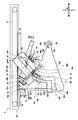
- the stacker 16 mainly includes a stage 16T, a stacker 30, a discharger 16J, a stacker frame 42, a moving arm 58, and a drive motor.
- the bundle conveying unit 3 and the moving arm 58R and the like are not shown for easy understanding.
- the stacker 30 is formed of a member having a substantially U-shaped cross section, and it is a bill by the stacker front side wall 30F, the stacker bottom plate 30D, the stacker right side wall 30R, the stacker left side wall 30L and the stacker rear side wall 30B.
- Form an integrated space 16S which is a space where the The accumulation storage 30 can be rotated clockwise and counterclockwise in the right side view with the accumulation storage frame fulcrum 42S as the accumulation storage rotation fulcrum as a support by the drive motor, the accumulation section drive transmission mechanism and the moving arm 58. It is configured.
- the accumulation storage rear side wall 30 ⁇ / b> B is formed in a comb shape along the left-right direction.
- a flat plate-like stage 16T for accumulating banknotes is moved up and down (up and down) and down (up and down) along the stage moving direction, which is the up and down direction, by the moving arm 58 inside the accumulation box 30 It is possible. As shown in FIG. 2, it is fixed to the storage case 10 (FIG. 1) on the front side of the accumulation container rear side wall 30B in the accumulation container accumulation state which is a state of the accumulation container 30 when accumulating bills on the stage 16T.
- a stacking guide 40 is provided to guide the rear end of the guide.
- the accumulation guide 40 is formed in a comb shape along the left-right direction.
- the comb teeth of the accumulation case rear side wall 30B and the comb teeth of the accumulation guide 40 are arranged to mesh with each other in the accumulation case accumulation state.
- the accumulation guide 40 passes the accumulation container rear side wall 30B from the rear side to the front side of the accumulation guide 40.
- the stage 16 T has a front end portion formed by forming a recessed portion 82 recessed rearward, which is a direction away from the side guide 70, at a position facing the side guide 70 described later. It is formed in a comb-tooth shape along the left-right direction, and is engaged with the side guide 70 and the outlet port lower guide portion 72 described later so as not to contact each other.
- the stage 16T has a rear end formed in a comb-like shape along the left-right direction so that it does not come in contact with the discharged bill transport guide 62, the discharge section upper guide 74, and the nipping transport guide lower guide 76 described later. It is engaged.
- the stacker 30 rotates clockwise with the stacker frame 42, and the stage 16T is inclined so that the rear end is lower than the front end. It becomes a state. Further, when transporting a bill bundle accumulated in the accumulation box 30 to the bundle conveyance unit 3 or receiving a bill bundle from the bundle conveyance unit 3, the accumulation box 30 in the accumulation box accumulation state is, as shown in FIG. The container frame 42 is rotated counterclockwise, and the stage 16T is in the horizontal delivery state.
- the stacking unit 16 discharges the banknotes from the discharge unit 16J to the stacking storage unit 30 and stacks the bank stack on the stage 16T, which is a state of the stacking storage unit 30,
- the stage 16T and the storage 30 are moved to the storage delivery state, which is the state of the storage 30 at the time of delivery with the unit 3.
- the release unit 16J is provided on the upper rear side of the accumulation space 16S in the accumulation case accumulation state.
- the accumulation roller 46 provided at a position facing the upper portion of the accumulation space 16S in the discharge unit 16J is conveyed by the conveyance unit 13 (FIG. 1) by rotating counterclockwise and clockwise in the drawing by the drive unit.
- the bill held is held and sent to the accumulation space 16S.
- a tongue 46 ⁇ / b> Z formed of an elastic member such as rubber is provided on the rotation shaft of the lower accumulation roller 46.
- the tongue 46 ⁇ / b> Z rotates counterclockwise with the lower accumulation roller 46 to strike the rear end portion of the bill fed to the accumulation space 16 ⁇ / b> S downward.
- casing 10 (FIG. 1) is provided above the discharge part 16J.
- a discharge banknote transport guide surface 62S is formed which inclines upward from the rear to the front.
- the discharge banknote transport guide surface 62S faces the upper surface of the banknote discharged from the discharge portion 16J into the accumulation space 16S, thereby preventing the banknote from rising upward and stably accumulating on the stage 16T. .
- the discharged bill guide portion 64 is formed on the lower rear side of the sandwiching and conveying guide 22 and on the rear upper side of the stacking space 16S.
- the lower end portion of the discharged bill guide portion 64 is formed in a comb-like shape along the left-right direction, and is engaged with the upper end portion of the discharged bill conveying guide 62 so as not to contact each other.
- the lower surface facing the stage 16T in the stack storage state in the discharge bill guide portion 64 maintains substantially the same angle as the discharge bill transport guide surface 62S in the storage stack state, and inclines upward from the rear to the front A discharge banknote guide surface 64S is formed.
- the discharge bill guide surface 64S is formed on the upper side of the bill discharged from the discharge part 16J.
- the discharged paper money guide portion 64 protrudes from the sandwiching conveyance guide 22 toward the discharged paper money conveyance guide 62. For this reason, although the lower end portion of the discharged bill guide portion 64 and the upper end portion of the discharged bill transport guide 62 mesh in the stacked storage stacked state (FIG. 2), the bill bundle is held between the stacking portion 16 and the bundle transport unit 3 In the nipping and conveying guide rear side state in which the accumulation holes 16H are opened and retracted from the moving path of the stage 16T when the delivery is performed, the discharged bill guiding portion 64 is the upper end of the discharged bill conveying guide 62 as shown in FIGS. A discharge portion upper space SJU is formed between the front end portion of the sandwiching and conveying guide 22 and the front end portion of the discharge portion upper guide 74 so as to move to the rear than the portion.
- Block stoppers 48 (48L and 48R) are attached. Further, two bill stoppers 48 are provided in the left-right direction at intervals slightly shorter than the length of the long side direction of the bill.
- the bill stopper 48 is configured to be rotatable about its lower end as a fulcrum, and is biased toward the discharge portion 16J (rear side) by a spring mechanism formed of an elastic member and biased by a locking member. It is regulated at a predetermined position.
- the bill stopper 48 pivots to the accumulation storage front side wall 30F (front side) about the pivot axis.
- the bill stopper 48 is formed with a bill collision surface 48S (FIG. 4) as a medium collision surface on which a bill collides on the rear wall surface, and a discharge direction in which bills are discharged from the discharge portion 16J in the bill collision surface 48S.
- a plurality of convex portions having a V-shaped cross section extending in the width direction (that is, the left-right direction) of the bill, which is orthogonal to the arrow, are provided in a sawtooth shape so as to line up vertically.
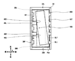
- the bill collision surfaces 48S of the building stoppers 48L and 48R are directed to the accumulation space 16S.
- BLf is discharged to the accumulation space 16S
- the vicinity of the left end of the tip of the bill BLf collides with the bill collision surface 48S of the bill stopper 48L.
- any end in the left-right direction which precedes in the bill is also referred to as a leading end.
- the leading end on the left side enters the leading end retraction space SBL.
- the leading end retracting space SB is located on the bill traveling direction side with respect to the bill collision surface 48S of the bill stopper 48, and the leading end of the bill that has been skewed enters the leading end of the bill. Acts as a space for preventing the front end of the bill from escaping from colliding with the accumulation front wall 30F.
- the bill BLf rotates clockwise as viewed from above with the bill stopper 48L as a fulcrum, and the vicinity of the right end portion of the tip of the bill BLf abuts the bill stopper 48R, which is a normal accumulation position on the stage 16T. It is corrected to the normal accumulation position Pbn.
- the bill stopper 48 absorbs the impact when the bill taken in from the discharge portion 16J collides with the bill stopper 48, whereby the bill (skew bill) is discharged obliquely from the discharge portion 16J.
- the skewed state is corrected and aligned to the normal accumulation position Pbn on the stage 16T.
- the stacking unit 16 can align and collect skewed banknotes.
- a drive motor that generates a driving force for driving the stacker 30 and the sandwiching conveyance guide 22.
- the storage case 30 pivots by transmitting the driving force generated by the driving motor from the stacking unit drive transmission mechanism connected to the output shaft of the driving motor via the moving arms 58 (58L and 58R).
- the nipping and conveying guide 22 is driven by transmitting the drive force generated by the drive motor from a guide drive transmission mechanism connected to the output shaft of the drive motor.
- the nipping and conveying guide 22 is provided with a conveying guide gear in the vicinity of the rear end of the nipping and conveying guide 22 and converts the driving force transmitted from the guide drive transmission mechanism into a longitudinal driving force by the conveying guide gear. , Reciprocate along the longitudinal direction.
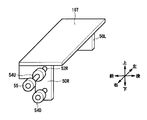
- a plate-like shaft support plate 50L and a shaft support plate 50R are provided on the lower side of the accumulation storage left side wall 30L and the accumulation storage right side wall 30R of the accumulation storage 30, respectively.
- pin shafts 52L and 52R extend from the shaft support plate 50L and the shaft support plate 50R toward the outside in the left-right direction, respectively.
- a cylindrical pin 54U is fixed to the pin shaft 52L at a position where it is inserted into the storage case frame groove 42G of the storage case frame 42L.
- a cylindrical pin 54U is fixed to the pin shaft 52R at a position where it is inserted into the storage case frame groove 42G of the storage case frame 42R.
- FIG. 5 illustrates only the stage 16T, the shaft support plate 50L, the shaft support plate 50R, the pin shaft 52R, the pin 54U, the pin 54D, and the pin 55.
- a cylindrical pin 54D is fixed to the lower side of the pin 54U in the shaft support plate 50L and the shaft support plate 50R (i.e., the lifting direction side of the stage 16T).
- a cylindrical pin 55 is fixed at a position where it is inserted into the stage guide groove 60 of the movable arm 58 outside the pin 54U in the pin shaft 52L and the pin shaft 52R in the left-right direction.
- cylindrical pins 56 are fixed to the rear ends of the stacker frame 42L and the stacker frame 42R.
- a plate-shaped storage case frame 42L and a storage case frame 42R (hereinafter collectively referred to as a storage case frame 42) are provided.
- the accumulation storage frame 42 is configured to be rotatable clockwise and counterclockwise in the right side view with the accumulation storage frame fulcrum 42S as a fulcrum by the drive motor, the accumulation section drive transmission mechanism, and the moving arm 58. Since the storage case frame 42L is configured in substantially the same manner as the storage case frame 42R and arranged symmetrically with the storage case frame 42R, the storage case frame 42R will be mainly described below.
- a storage case frame groove 42G is formed in a straight line along the stage movement direction along the vertical direction which is the movement direction of the stage 16T.
- a pin 54U and a pin 54D are slidably inserted in the storage frame groove 42G with respect to the storage frame groove 42G.
- the stage 16T is configured to be linearly reciprocally movable upward and downward in FIG. 6, which is the stage movement direction.
- the stage 16T in the stage accumulation state which is a state of the stage 16T in which the bills are discharged from the discharge unit 16J to the accumulation box 30 and the bills are accumulated, is in the state of the stage 16T when delivering the bill bundle to the bundle conveyance unit 3
- An upward direction extending in a stage transfer direction to a certain stage delivery state is also referred to as a lifting direction
- a downward direction in which the stage 16T in the stage delivery state goes to the stage accumulation state along the stage movement direction is also referred to as a lifting direction.
- the pin 54D is located at the lower end of the accumulation case frame groove 42G.
- a moving arm 58L and a moving arm 58R are provided on the left and right outer sides of the stacker frame 42.
- the moving arm 58 is configured to be rotatable clockwise and counterclockwise in the figure with the moving arm fulcrum 38 as a fulcrum by a drive motor and an accumulation unit drive transmission mechanism.
- Rtl counterclockwise in right side view
- the moving arm 58L is configured in substantially the same manner as the moving arm 58R, and arranged symmetrically with the moving arm 58R. Therefore, the moving arm 58R will be mainly described below.
- An accumulation storage frame guide groove 59 and a stage guide groove 60 are formed in the moving arm 58R.
- the storage case frame guide groove 59 is substantially L-shaped in a side view, and a pin 56 is inserted so as to slide in contact with the storage case frame guide groove 59.
- an angle holding portion 59A and a rotation drive portion 59B are formed in the storage case frame guide groove 59.
- the angle holding portion 59A has an arc shape centering on the movable arm fulcrum 38, and is extended from the end on the accumulation transfer drive direction Rds side of the move arm 58R in the up-and-down transfer drive direction Rd1.
- the rotation drive portion 59B has a substantially linear shape, and is directed from the end portion on the raising and lowering transition drive direction Rdl side of the angle holding portion 59A toward the moving arm fulcrum 38 than the arc shape centered on the moving arm fulcrum 38.
- the movable arm 58R is extended to the end on the side of raising and lowering transition drive direction Rdl.
- the pivot drive unit 59B slides the pin 56 when rotating the stacker 30 between the stacker stacking state and the stacker delivery state.
- the stage guide groove 60 is disposed in front of the storage case frame guide groove 59 and is substantially L-shaped as if the storage case frame guide groove 59 is rotated 90 degrees in a side view. Pins 55 are inserted.
- a rotation holding portion 60A, an elevation driving portion 60B and a pin holding portion 60C are formed in the stage guide groove 60.
- the rotation holding portion 60A has a curved shape, and is extended in the accumulation transfer drive direction Rds from the vicinity of the end portion of the movable arm 58R on the side of the elevation transfer drive direction Rdl.
- the rotation holding unit 60A slides the pin 56 when rotating the storage case 30 between the storage case and the storage case delivery state.
- the elevation driving unit 60B has a substantially linear shape, and extends from the end on the accumulation transfer driving direction Rds side of the rotation holding unit 60A radially from the moving arm fulcrum 38 to the vicinity of the front end of the moving arm 58R. It is done.
- the elevation driving unit 60B slides the pin 55 when linearly moving the stage 16T between the stage accumulation state and the stage delivery state.
- the pin holding portion 60C is extended in the accumulation transfer drive direction Rds from an end portion on the radial direction side separated from the moving arm fulcrum 38 in the elevation driving portion 60B.
- the pin holding portion 60C holds the position of the pin 56 by fitting the pin 56 when the stage 16T is in the stage delivery state.
- a nipping conveyance guide detection sensor (not shown) for detecting the nipping conveyance guide 22 is provided.
- the nipping and conveying guide detection sensor is an optical sensor constituted by a combination of a light emitting element for emitting predetermined detection light and a light receiving element for receiving the detection light, and the light path of the detection light is made to intersect the nipping and conveyance guide 22 There is.
- the pinching conveyance guide detection sensor notifies the control unit 4 of the light reception result of the detection light. Based on the light reception result, the control unit 4 determines whether the nipping and conveying guide 22 is in the nipping and conveying guide rear side state or the nipping and conveying guide front side state.
- the storage box 30 is provided with a storage box detection sensor for detecting the storage box 30.
- the storage detection sensor is an optical sensor, and crosses the optical path of the detection light with the movement path of the storage detection plate fixed to the storage 30.
- the accumulation storage detection sensor notifies the control unit 4 of the light reception result of the detection light. Control unit 4 determines, based on the light reception result, whether storage shed 30 is in the storage shed storage state or the storage shed delivery state.
- the accumulation storage frame 42 is provided with a stage detection sensor that detects the stage 16T.
- the stage detection sensor is an optical sensor, and intersects the optical path of the detection light with the movement path of the stage 16T.
- the stage detection sensor notifies the control unit 4 of the light reception result of the detection light.
- the control unit 4 determines whether the stage 16T is in the stage accumulation state or the stage delivery state based on the light reception result.
- a bill stopper upper space SBU is formed between the upper end of the bill stopper 48 and the rear end of the dispensing port transport guide 24 in the stack storage delivery state.
- the stacking unit 16 is provided with a banknote alignment mechanism 68 that maintains and maintains the aligned state by correcting and suppressing positional deviation of the banknotes placed on the stage 16T, and keeping the banknotes in a normal position.
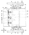
- the banknote alignment mechanism 68 includes a front side guide 68F as a discharge direction side guide including the side guide 70 and the outlet port conveyance guide lower guide portion 72, a discharge portion upper side guide 74 and a nipping conveyance guide lower side guide portion 76. It is comprised by the back side guide 68B as a discharge part side guide.
- FIG. 3 Configuration of side guide
- the storage housing 10 (FIG. 1) on the front side of the stage 16T in the stack storage delivery state (FIGS. 6, 7 and 13), that is, on the opposite side of the stage 16T with respect to the discharge part 16J.
- the side guide 70L is between the building stopper 48L and the accumulation storage left side wall 30L in the accumulation storage delivery state
- the side guide 70C is between the building stopper 48L and the construction stopper 48R in the accumulation storage delivery state
- the side guide 70R is They are respectively located between the building stopper 48R and the accumulation storage right side wall 30R in the accumulation storage delivery state.
- the side guides 70 mesh with the stage 16T and the bill stopper 48 so as not to contact each other in the storage delivery state. Further, the upper end portion of the side guide 70 is bent forward, and the bent portion is intruding into the outlet port lower guide portion 72.
- a side guide surface 70S which is a flat surface along the stage moving direction is formed on the rear side of the side guide 70 facing the discharge part 16J.
- the position in the front-rear direction of the side guide surface 70S is set at the front end of the bill accumulation position, which is an intersection point of the bill stopper 48 and the upper surface of the stage 16T in a right side view.
- the banknotes are set so as to be stacked at the normal stacking position Pbn (FIG. 7) in which the front end is positioned behind the front edge of the bill stacking position.
- the side guides 70 are arranged such that the side guide surfaces 70S are separated forward of the bill colliding surface 48S of the bill stopper 48 in the accumulation case accumulation state.
- the bills are accumulated on the stage 16T such that the front end is positioned behind the front end of the bill accumulation position.
- the side guide 70 is extended from the lower side of the stage 16T in the accumulation storage delivery state to the lower side of the outlet port conveyance guide 24.
- the side guides 70 are located forward of the building stopper 48 in the accumulation space separation direction from the building stopper 48 in the accumulation case accumulation state (FIGS. 2, 3 and 12), and also the accumulation case delivery In the state (FIG. 6, FIG. 7 and FIG. 13), it is located rearward, which is closer to the accumulation space closer to the discharge part 16 J than the bill stopper 48.
- the side guide 70 causes the side guide surface 70S to abut on the front end portion of the bill moved forward by the centrifugal force when rotating from the stacked storage state to the stacked storage delivery state, thereby the bill Prohibit the forward movement of the bill and place the bill behind the front end of the bill accumulation position.
- a dispensing port transport guide lower guide portion 72 which protrudes downward is formed at the rear end portion of the dispensing port transport guide 24 at the rear end portion of the dispensing port transport guide 24 .
- the lower side of the lower end portion of the dispensing port transport guide lower guide portion 72 is formed in a comb shape along the left-right direction, and the upper end portion of the side guide 70 and the pinch transport guide lower side guide of the sandwich transport guide 22 The portion 76 and the stage 16T are engaged so as not to contact each other.
- a dispensing port transport guide lower guide surface 72S which is a surface along the vertical direction is formed on the rear surface opposite to the moving path of the stage 16T in the dispensing port transport guide 24, a dispensing port transport guide lower guide surface 72S which is a surface along the vertical direction is formed.
- the dispensing port transport guide lower guide surface 72S is formed in front of the front end portion of the moving path of the bill bundle which is accumulated at the normal accumulation position Pbn and rises, and is further than the side guide surface 70S of the side guide 70. It is formed slightly forward. As a result, the dispensing port transport guide lower guide portion 72 prevents the front end portion of the bill whose front end portion has risen along the side guide surface 70S from being caught by the dispensing port transport guide lower guide portion 72. , The bill bundle can be raised smoothly.
- a plurality of discharge unit upper guides 74 which are plate-shaped and guide the rear end of the rising bill are fixed on the upper side of the discharge bill conveyance guide 62.
- the plurality of discharge unit upper guides 74 are formed in a comb shape along the left and right direction as a whole by being spaced apart from each other in the left and right direction, and the lower end portion of the nipping and conveyance guide lower guide 76 and They are meshed with each other so as not to be in contact with the discharged bill guide portion 64.
- a discharge portion upper guide surface 74S is formed which is inclined upward and curved as it goes from the rear to the front.
- the discharge section upper guide surface 74S is formed rearward of the rear end portion of the moving path of the bill bundle accumulated and rising at the normal accumulation position Pbn.
- the bill when the bill is displaced backward when the stage 16T is lifted, the bill has its rear end portion upward from the bottom to the discharge portion upper guide surface 74S inclined with respect to the gravity direction. It rises while abutting towards the head. For this reason, the discharge unit upper guide 74 brings the shifted banknotes forward, and raises the stage 16T while correcting the position.
- FIGS. 10 and 14 At the front end portion of the sandwiching and transporting guide 22, a plurality of sandwiching and transporting guide lower guides 76 projecting downward are formed.
- the plurality of sandwiching and conveying guide lower guides 76 are spaced apart from each other in the left-right direction, so that the lower end of the lower end as a whole is formed in a comb shape along the left-right direction.
- the front upper end portion 74 and the rear end portion of the delivery port lower guide portion 72 are engaged with each other so as not to contact each other.
- a holding and conveying guide lower side guide surface 76S which is a surface along the vertical direction, is formed.
- the nipping and conveying guide lower guide surface 76S is formed rearward of the rear end portion of the moving path of the bill bundle which is accumulated at the normal accumulation position Pbn and rises, and the upper guide surface of the discharge portion upper guide 74 It is almost flush with the 74S.
- the nipping and conveying guide lower guide portion 76 is brought up by the stage 16T while being in contact with the back of the bill and preventing further backward movement.
- the side guide 70 is located on the accumulation space separation side with respect to the bill stopper 48. That is, the side guide 70 is located outside the accumulation space 16S.
- the stacking unit 16 rotates the stacking roller 46 to discharge the banknotes transported from the transport unit 13 into the stacking space 16S. Subsequently, the stacking unit 16 knocks the rear end portion of the bill colliding with the bill stopper 48 to the storage bottom plate 30D with the tongue piece 46Z so that the bill is transferred to the stage 16T before the subsequent bills are sent out to the accumulation space 16S. Accumulate. At this time, since the stage 16T is inclined backward with the storage case frame 42, the banknotes are stacked so that they overlap vertically with the rear ends of the plurality of bills being in contact with the collection guide 40 by aligning them. .
- the stacking unit 16 moves the moving arm 58 up and down as shown in FIG. 6 about the moving arm fulcrum 38 as an axis by rotating the drive motor. Rotate in the direction Rdl.
- the movable arm 58 rotates the storage case frame 42 in the raising / lowering rotation direction Rtl by rotating while sliding the pin 56 along the rotation drive portion 59B of the storage case frame guide groove 59.
- the movable arm 58 is rotated while sliding the pin 55 along the rotational holding portion 60A of the stage guide groove 60, so that the pin 55 is interposed between the rotational holding portion 60A and the elevation driving portion 60B. Is located.
- the rear end of the plurality of banknotes abuts against the inner wall surface of the rear side wall 30B of the plurality of bills by the collection rear side wall 30B passing over the collection guide 40 from the rear to the front, and the rear end is along the vertical It will be in a state of alignment.
- the stacker 30 is in the stacker delivery state
- the stage 16T is in the stage stack state
- the nipping and conveying guide 22 is in the nipping and conveying guide front side.
- the stacking unit 16 tilts the stage 16T downward to stack the banknotes, and rotates the storage rear side wall 30B so as to overtake the stacking guide 40 from the rear toward the front. Therefore, the stacking unit 16 can stack the bill bundle in a state of being close to the rear of the inside of the stacker 30. In this state, the distance between the bill stopper 48 and the rear wall surface of the stack storage side wall 30F at which the front ends of the bundle of bills are aligned becomes wider than the length of the bill in the front-rear direction. Further, the bill bundle is accumulated so that the position in the front-rear direction of the front end is out of the range of the rotation trajectory of the tongue 46Z.
- the bill bundle contacts the bill stopper 48 when raising the bill bundle without moving the bill stopper 48 itself so as to retract the bill bundle from the moving path of the bill bundle which is rising. It can prevent that 48 becomes a load.
- the stacking unit 16 lifts the bill bundle without moving the discharging unit 16J and the stacking guide 40 itself so as to retract from the moving path of the rising bill bundle, and the discharging unit 16J (especially the tongue 46Z) or the stacking guide It is possible to prevent the bill bundle from coming into contact with 40 and causing the discharge portion 16J or the accumulation guide 40 to be a load.
- the storage front wall 30F gradually approaches the side guide 70 as it moves from the accumulation storage accumulation state (FIG. 12) to the accumulation storage delivery state (FIG. 13).
- the side guide 70 eventually enters the recess 82 (FIG. 7) of the stage 16T, the upper end is positioned closer to the accumulation space than the bill stopper 48 as shown in FIG. It will be located in
- the stacker 30 when the stacker 30 is rotated about the stacker frame fulcrum 42S in the raising / lowering rotational direction Rtl from the stacker stacking state to the stacker delivery state, the stacker 30 is A centrifugal force acts on the accumulated bills in a direction of centrifugal force which is a direction from the accumulation storage frame fulcrum 42S to the accumulation front wall 30F (that is, the bill stopper 48).
- the stacking unit 16 further rotates the moving arm 58 in the raising and lowering transition driving direction Rdl around the moving arm fulcrum 38 as shown in FIG. 11 by rotating the driving motor.
- the movable arm 58 rotates while sliding the pin 55 along the elevation drive unit 60B of the stage guide groove 60, thereby sliding and holding the pins 54U and 54D along the accumulation storage frame groove 42G.
- the stage 16T is moved upward to be in the stage delivery state shown in FIG.
- the moving arm 58 holds the angle of the storage case frame 42 (that is, the storage case 30) by rotating while sliding the pin 56 along the angle holding portion 59A of the storage case frame guide groove 59.
- the pin 56 is positioned at the end on the side of the accumulation transfer drive direction Rds of the angle holding portion 59A.
- the accumulation unit 16 moves the sandwiching conveyance guide 22 in the backward direction in which the accumulation hole 16H is opened.
- the stacking unit 16 stacks the banknote bundles stacked on the stage 16T.
- the bundle can be delivered to the bundle conveyance unit 3 without breaking the shape.
- the stacker 30 is in the stacker delivery state
- the stage 16T is in the stage delivery state
- the pinching conveyance guide 22 is in the pinching conveyance guide rear side.
- the pin holding portion 60C abuts on the lower side of the pin 55 and restricts the downward movement of the pin 55 by fitting the pin 55 into the pin holding portion 60C. For this reason, when a load is applied from the top to the bottom to the stage 16T in the stage delivery state, the stacking unit 16 lowers the stage 16T, and the positional relationship between the bill bundle and the pushing portion 25 (FIG. 1) deviates and is conveyed It is possible to prevent the occurrence of bundle deviation at times.
- the stage 16T descends from the stage delivery state to the stage accumulation state, the movable arm 58 is pivoted in the accumulation shift drive direction Rds, and the pin 55 is detached from the pin holding portion 60C and moved to the elevation driving portion 60B.
- the stage 16T can be lowered without being affected by the pin holding portion 60C.
- the side guide 70 causes the side guide surface 70S to abut on the front end portion of the bill that has moved to the front side of the normal accumulation position Pbn, thereby preventing further forward movement.
- the bill bundle is raised by the stage 16T.
- the delivery port lower transfer guide 72 is a delivery port transfer guide at the front end portion of the bill that has moved to the front side of the normal accumulation position Pbn with respect to the bill bundle located above the upper end of the side guide surface 70S.
- the discharge unit upper guide 74 brings the misplaced banknote forward by correcting the position by bringing the discharge unit upper guide surface 74S into contact with the rear end portion of the banknote that has moved to the rear side beyond the normal stacking position Pbn. Then it is raised by stage 16T.
- the nipping and conveying guide lower guide portion 76 nipping and conveying guide at the rear end portion of the bill that has moved to the rear side from the normal accumulation position Pbn with respect to the bill bundle positioned above the upper end of the discharger upper side guide surface 74S.
- the bill dispenser 1 (FIG. 1) transfers the bill bundle from the stacking unit 16 to the bundle conveyance unit 3 to make the upper belt 21 travel, and the dispensing port 26 from the bundle conveyance path 3Y in the upper part of the accumulation hole 16H.
- the bill bundle is transported from the stage 16T in the dispensing direction by moving the pushing portion 25 in the dispensing direction which is the forward direction toward the horizontal direction.
- control unit 4 first moves the stage 16T downward and moves the nipping and conveying guide 22 forward to close the stacking hole 16H of the stacking unit 16. Further, the control unit 4 moves the extrusion unit 25 to the rearmost side.
- the control unit 4 causes the feeding unit 12 to sequentially feed the banknotes of the denomination and the number corresponding to the withdrawal amount from the banknote storage 11, conveys upward by the conveyance unit 13, and makes the discrimination unit 14 discriminate.
- the control unit 4 determines the transport destination as the accumulation unit 16 or the reject storage 17 depending on whether or not the banknotes can be dispensed.
- the control unit 4 causes the banknotes identified by the identification unit 14 to be transported backward and upward by the transport unit 13 to reach the switching unit 15.
- the switching unit 15 switches the traveling direction according to the transport destination determined for each of the banknotes under the control of the control unit 4 and advances the traveling direction to the stacking unit 16 or the reject storage case 17.
- the accumulation unit 16 discharges the conveyed banknotes into the accumulation space 16S by the discharge unit 16J, and accumulates the sheet surface on the stage 16T in an inclined posture inclined downward. At this time, since the upper side of the accumulation hole 16H is closed by the holding conveyance guide 22, the accumulation unit 16 prevents the bill discharged from the discharge unit 16J from rising upward, and stably accumulates it on the stage 16T. . Further, the reject storage case 17 discharges the transported banknotes by the discharge unit 17J into the rejected banknote storage space 17SR and stores them.
- the control unit 4 sequentially counts the denominations and the number of banknotes whose conveyance destination is the accumulation unit 16, that is, the banknotes accumulated in the accumulation unit 16, and the banknote storage is performed when the aggregated amount reaches the withdrawal amount. Stop the delivery of banknotes from 11. As a result, on the stage 16T of the stacking unit 16, a bill bundle W in which bills of the withdrawal amount are stacked in a bundle is placed.
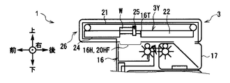
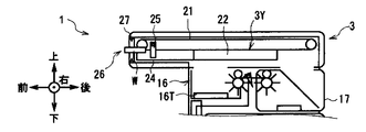
- the control unit 4 rotates the stacker 30 and the stage 16T to a horizontal posture, and as shown in FIG. 15B, moves the nipping and conveying guide 22 to the rear to open the stacking holes 16H of the stacker 16
- the control unit 4 aligns the upper surface of the stage 16T to the same height as the upper surfaces of the sandwiching conveyance guide 22 and the dispensing opening conveyance guide 24, and configures a part of the bundle conveyance path 3Y by the stage 16T.
- the bill bundle W on the stage 16T is positioned in the bundle conveyance path 3Y.
- control unit 4 causes the bill bundle W to advance forward along the bundle conveyance path 3Y by causing the upper belt 21 to travel forward and moving the pushing portion 25 forward.
- the control unit 4 detects that the bill bundle W has reached the outlet 26 based on the notification from the outlet sensor 27, the control unit 4 stops the traveling of the upper belt 21 as shown in FIG. 15C. At this time, the control unit 4 moves the stage 16T downward, and ends the dispensing operation.
- the bill dispenser 1 exposes a part of the bill bundle W from the dispensing port 26 and holds the vicinity of the rear end of the bill bundle W by the upper belt 21 and the dispensing port conveyance guide 24 as follows. The user can take out the bill bundle W.
- control unit 4 monitors whether the bill bundle W has been taken out from the outlet 26 based on the notification from the outlet sensor 27, and a predetermined standby time (for example, 30 seconds) has elapsed. If it is not taken out, the take-in operation to take in the bill bundle W is started.
- a predetermined standby time for example, 30 seconds
- the control unit 4 causes the bill bundle W to be taken into the bundle conveyance path 3Y by displacing the push-out unit 25 and causing the upper belt 21 to travel backward. It travels backward along the bundle conveyance path 3Y.
- the control unit 4 detects that the bill bundle W has reached the rear of the push-out unit 25 by the sensor, the control unit 4 displaces the push-out unit 25 downward and moves it to the rear to move the bill bundle W to the rear.
- the control unit 4 displaces the push-out unit 25 downward and moves it to the rear to move the bill bundle W to the rear.
- the control unit 4 causes the bill bundle W to drop from the bundle conveyance path 3Y, and the inside of the forgotten bill storage space 17SL of the reject storage 17 And the loading operation is finished.
- the bill dispenser 1 takes in the forgotten bill bundle that the user forgot from the dispensing port 26 and stores it in the reject storage 17.
- the stacking unit 16 stacks the bills by inclining the stage 16T downward so that the rear side close to the discharge part 16J in the stage 16T is positioned lower than the front side separating from the discharge part 16J. I did it.
- the stacker 30 can stack the bundle of bills on the stage 16T in a uniform shape by aligning the rear end faces of the banknotes in the storage-stacking state and stacking them in the stacking space 16S.
- the stacking unit 16 forms leading end withdrawal spaces SB on the left and right sides of the bill stopper 48, and causes the leading ends of the skewed bills to collide with the bill stopper 48 while entering the leading end withdrawal spaces SB. Correct the skew.
- the stacking unit 16 can align the rear end face of the bill bundle by discharging the bill to the stacking space 16S in a state where the stacker 30 is inclined, but then the bundle conveyance path 3Y along the horizontal direction In order to deliver the bill bundle, it is necessary to turn the accumulation box 30 horizontally. At that time, if the side guide 70 does not exist, the leading end of the bill is in the leading end withdrawal space SB, which is a space necessary for correcting the skew of the bill by the centrifugal force when the stacker 30 rotates. There is a possibility of getting in.
- the stacking unit 16 retracts from the inside of the accumulation space 16S in the accumulation case accumulation state, and the side guide surface 70S fills the accumulation space 16S so as to fill the leading end evacuation space SB as it progresses to the accumulation case delivery state. It includes a projecting side guide 70.
- the stacking unit 16 can prevent the side guides 70 from interfering with the bills when stacking the bills on the stage 16T in the stacked storage state, and also proceeds from the stacked storage state to the stacked storage delivery state.
- the side guide surface 70S of the side guide 70 By bringing the side guide surface 70S of the side guide 70 into contact with the bill which has been moved in the direction of centrifugal force, it is possible to suppress the movement of the bill and return it to the normal accumulation position Pbn.
- the stacking unit 16 is a side guide surface 70S that is a continuous surface from the stage accumulation state on the stage 16T to the stage delivery state on the front side of the normal accumulation position Pbn, and the discharge port conveyance guide lower guide surface A side guide 70 and a delivery port lower transfer guide 72 are provided so that 72S is formed. Furthermore, on the rear side of the normal accumulation position Pbn, the accumulation unit 16 continues from the upper side of the accumulation container rear side wall 30B to the stage delivery state on the stage 16T, and the discharge unit upper side guide surface 74S and the clamping conveyance It includes a discharge unit upper guide 74 and a nipping and conveying guide lower guide 76 so that a guide lower guide surface 76S is formed.
- the stacking unit 16 suppresses the positional deviation of the bill bundle, whereby the bill enters the bill stopper upper space SBU or the discharger upper space SJU, or the bill stopper upper space SBU or the discharger upper space SJU. Prevents the bill bundle from being pinched between the stage 16T and the outlet port conveyance guide 24 or the pinch conveyance guide 22 while the stage 16T moves up, and prevents the bill bundle from being kept aligned.
- the bundle can be delivered from the stage 16T to the bundle conveyance path 3Y.
- the bill dispenser 1 includes the bill storage 11 for storing bills, the stacking unit 16 for stacking the bills drawn out from the bill storage 11 and transported, and the bills stacked in the stacking unit 16.
- a stack transport unit 3 is provided which transports a stack and delivers the stack to the user, and the stack unit 16 has a stack storage space 16S for stacking banknotes formed therein, and switches to an inclined posture and a horizontal posture; 11.
- a side guide 70 for regulating the position of the bill bundle accumulated on the stage 16T when switching to the attitude.
- the bill dispenser 1 when moving the bill bundle from the inclined posture to the horizontal posture, the bill dispenser 1 suppresses the movement of the bill by the centrifugal force, and delivers the bill bundle while maintaining the shape of the bill bundle. It can be transported in the direction.
- the banknote dispensing machine 101 according to the second embodiment is different from the banknote dispensing machine 1 according to the first embodiment in that a stacking unit 16 is provided instead of the stacking unit 116. It is different from However, the other configuration is the same as that of the bill dispenser 1.
- the stacking unit 116 according to the second embodiment is different from the banknote alignment mechanism 68 in that the banknote alignment mechanism 168 is provided in the first embodiment. It differs from the accumulation unit 16 according to the form. However, the other configuration is the same as that of the stacking unit 16.
- the bundle conveyance unit 3 and the moving arm 58R and the like are not shown for easy understanding.
- the rear guide 168B is different from the rear guide 68B of the banknote alignment mechanism 68 according to the first embodiment, but is otherwise configured in the same manner. There is.
- the rear guide 168B is different from the rear guide 68B in that the discharge portion upper side guide 74 of the rear guide 68B is omitted and an elevating movable guide 80 is added.
- the other configuration is the same as the rear guide 68B.
- the elevating movable guide 80 is a plate-like member, and is provided behind the stage 16T in the stage accumulation state.
- the upper end portion of the elevating movable guide 80 is formed in a comb-like shape along the left-right direction, and engages with the lower end portion of the nipping and conveying guide lower guide portion 76 in the stage delivery state (FIG. 19).
- a vertically movable guide surface 80S which is a surface along the vertical direction and is flush with the rear storage sidewall 30B, is formed on the front surface of the movable movable guide 80 facing the moving path of the stage 16T.
- the elevating movable guide surface 80S is formed rearward of the rear end portion of the moving path of the rising bill bundle, and is further than the surface of the nipping and conveying guide lower guide 76 of the nipping and conveying guide lower guide 76. It is formed slightly forward. As a result, the elevating movable guide 80 prevents the trailing end of the bill whose rear end has risen along the elevating movable guide surface 80S from being caught by the nipping / conveying guide lower guide portion 76 and makes the bill bundle smooth. It can be raised.
- the elevating movable guide 80 is mounted so as to be reciprocatively movable up and down with respect to the stage 16T via a hole formed in the stage 16T while keeping the elevating movable guide surface 80S in the vertical direction .
- the lower end portion of the movable movable guide surface 80S is positioned lower than the upper surface of the stage 16T, so that the rear direction of the bill placed on the stage 16T is obtained.
- the upper end of the elevating movable guide surface 80S is positioned lower than the upper surface of the stage 16T, whereby the bill placed on the stage 16T Move in the retracted state that does not restrict movement in the backward direction.
- the upper end portion of the vertically movable guide 80 has substantially the same height as the upper end portion of the accumulation container rear side wall 30B.
- the lifting movable guide 80 is biased in the lifting direction by attaching the upper end of a spring, which is a tension spring whose lower end is attached to the stage 16T.
- a holding / conveying guide lower guide portion 76 as an elevation restricting member is provided above the elevating and movable guide 80 in the storage container delivery state (FIGS. 18 and 19).
- the holding conveyance guide lower guide portion 76 abuts on the movable movable guide 80 when the movable movable guide 80 ascends to the vicinity of the accumulation hole 16H and the stage 16T enters the stage delivery state, and moves in parallel in the downward retraction direction
- the elevating movable guide 80 is in the bill position correction state. Subsequently, when the stage 16T ascends, the vertically movable guide 80 ascends with the stage 16T.
- the elevating movable guide 80 brings the elevating movable guide surface 80S into contact with the rear end portion of the bill that has moved to the rear side beyond the normal accumulation position Pbn, thereby further moving backward.
- the bill bundle is raised by the stage 16T while preventing movement.
- the upward movement of the elevating movable guide 80 is restricted by the upper end surface coming into contact with the lower end portion of the holding conveyance guide lower guide portion 76. Ru.
- the elevating movable guide 80 moves in the retraction direction with respect to the stage 16T against the biasing force of the spring as the stage 16T rises.
- the movable movable guide 80 brings the movable movable guide surface 80S into contact with the rear end portion of the bill that has moved to the rear side from the normal accumulation position Pbn, thereby preventing further movement to the rear. Raise the bill bundle by 16T.
- the upper surface of the stage 16T moves upward from the upper end surface of the elevating movable guide 80 while the elevating movable guide 80 is positioned below the sandwiching and conveying guide lower guide portion 76.
- the holding conveyance guide lower guide portion 76 holds the conveyance guide at the rear end portion of the bill moved to the rear side from the normal accumulation position Pbn with respect to the bill bundle positioned above the upper end of the elevating movable guide surface 80S.
- the bill dispenser 1 (FIG. 1) transfers the bill bundle from the stacking unit 16 to the bundle conveyance unit 3 to make the upper belt 21 travel, and the dispensing port 26 from the bundle conveyance path 3Y in the upper part of the accumulation hole 16H.
- the bill bundle is transported from the stage 16T in the dispensing direction by moving the pushing portion 25 in the dispensing direction which is the forward direction toward the horizontal direction.
- the elevating movable guide 80 descends together with the stage 16T, and is retracted in the stage accumulation state.
- the stacking unit 116 positions the movable movable guide surface 80S on the rear side of the stage 16T from the stage accumulation state on the stage 16T to the lower side in the stage delivery state on the rear side of the normal accumulation position Pbn.
- the movable movable guide 80 is raised as the stage 16T ascends.
- the stacking unit 16 suppresses the positional deviation of the bill bundle, whereby the bill enters the discharge unit front space SJB, and the stage 16T ascends while the bill enters the discharge unit front space SJB. It is possible to prevent the bill bundle from being sandwiched between the discharged bill transport guide 62 and to transfer the bill bundle from the stage 16T to the bundle transport path 3Y while maintaining the alignment state of the bill bundle.
- the height of the movable movable guide 80 is substantially equal to that of the rear storage side wall 30B.
- the accumulation unit 116 restricts the elevation by bringing the elevating movable guide 80 into contact with the sandwiching conveyance lower guide 76.
- the stacker 116 delivers the bill bundle from the stage 16T to the bundle conveyance path 3Y and conveys the bill bundle along the horizontal direction by the bundle conveyance path 3Y, the raising and lowering movable guide 80 is moved to the bill bundle etc. It can be made not to interfere.
- stacking unit 116 according to the second embodiment has the same function and effect as the stacking unit 16 according to the first embodiment.
- the side guide 70 is fixed to the storage case 10 .
- the present disclosure is not limited thereto, and the side guide 70 is configured to be reciprocally movable in the accumulation space proximity direction which is a direction approaching the accumulation space 16S and in the accumulation space separation direction which is a direction away from the accumulation space 16S.
- a predetermined biasing member may be biased toward the accumulation space.
- the side guide 70 can absorb the momentum of the bill moved in the centrifugal force direction.
- the side guide 70 has the shortest position among the banknotes handled in the banknote dispenser 1 with the shortest length in the long-side direction being the most misaligned in any of the left-right direction of the banknotes, and the maximum skew assumed in advance.
- the side guide surface 70S may be disposed in a range that can abut on both left and right end portions of the bill even when the sheet is skewed by an amount.
- the storage unit 2 includes the front face machine in which the bill storage case 11 is attached to and detached from the storage case 10 from the front side which is the same side as the withdrawal port 26 with respect to the withdrawal port 26 provided on the front side. It is desirable that the upper end portion of the side guide 70 is not extended to the upper side of the lower end portion of the bundle conveyance unit 3 in the case where the two are shared.
- the nipping and conveying guide lower guide portion 76 is provided in the nipping and conveying guide 22 and the discharging portion upper guide 74 is provided in the discharged bill conveying guide 62.
- the present disclosure is not limited to this, and the holding and conveying guide lower guide portion 76 may be omitted, and the upper end of the discharge portion upper portion guide 74 of the discharged bill conveying guide 62 may extend to the vicinity of the upper surface of the stage 16T in the stage delivery state. Good.
- the stage 16T is raised while maintaining the horizontal state of the plate surface.
- the present disclosure is not limited to this, and raises the stage 16T while sliding the front end surface of the bill bundle on the side guide surface 70S and the dispensing port transport guide lower guide surface 72S in a state where the plate surface is lowered forward.
- the movable up and down movable guide 80 and the nipping and conveying guide lower guide portion 76 can be omitted.
- the elevation is restricted by bringing the elevating movable guide 80 into contact with the nipping and conveying guide lower guide portion 76
- the present disclosure is not limited to this, and the elevation may be restricted by bringing the elevating movable guide 80 into contact with another member other than the holding and conveying guide lower guide portion 76.
- the present disclosure is not limited to this, and the elevating movable guide 80 may be provided instead of the accumulation storage rear side wall 30B.
- the present disclosure is not limited to this, and one bill stopper having a bill colliding surface 48S extending from the bill stoppers 48R to 48L and having a length in the left-right direction slightly shorter than the length in the long side direction of the bill may be provided.
- the side guides 70 may be provided so as to fill the left and right outer spaces of the bill stopper.
- the side guide 70, the dispensing port transport guide lower guide portion 72, the discharge portion upper guide 74, and the sandwich transport guide lower guide portion 76 are provided as the bill positioning mechanism 68. I mentioned the case.
- the present disclosure is not limited to this, and even if any one or a plurality of combinations of the dispensing port transport guide lower guide portion 72 other than the side guide 70, the discharge portion upper guide 74 and the sandwich transport guide lower guide portion 76 are omitted. Good.
- the vertically movable guide 80 of the second embodiment may be combined with the above-described banknote alignment mechanism 68 of the first embodiment.
- the present disclosure is not limited to the above-described embodiments and other embodiments. That is, the present disclosure can be applied to an embodiment in which any or all of the above-described embodiments and any of the other embodiments described above are arbitrarily combined or an embodiment in which a part is extracted. It is.
- the bill storage case 11 as the medium storage case, the accumulation case 30 as the accumulation case, the discharge part 16J as the discharge part, the bill stopper 48 as the stopper, and the stage as the stage A media transfer device is provided by stacking units 16 and 116 as a stacking unit having a 16T, a movable arm 58 as a drive mechanism, and a side guide 70 as a guide member, and a bundle conveyance unit 3 as a bundle conveyance unit.
- stacking units 16 and 116 as a stacking unit having a 16T, a movable arm 58 as a drive mechanism, and a side guide 70 as a guide member, and a bundle conveyance unit 3 as a bundle conveyance unit.
- the present disclosure is not limited to this, and includes a media storage having various configurations, a storage, a discharge unit, a stopper, a stage, a drive mechanism, a guide member, a bundle transport unit, and the like.
- the media delivery device may be configured by
- the accumulation storage 30 as the accumulation storage, the discharge part 16J as the discharge part, the building stopper 48 as the stopper, the stage 16T as the stage, and the moving arm 58 as the driving mechanism
- the stacking units 16 and 116 as the medium stacking and delivering mechanism are configured by the side guides 70 as the guide members.
- the present disclosure is not limited to this, and the medium accumulation and delivery mechanism may be configured by the accumulation case of various configurations, the discharge unit, the stopper, the stage, the drive mechanism, and the guide member.
- the present disclosure can also be used, for example, in a bill dispensing machine that stores bills in a removable bill storage and dispenses the bills according to the user's operation.
Landscapes
- Physics & Mathematics (AREA)
- General Physics & Mathematics (AREA)
- Engineering & Computer Science (AREA)
- Mechanical Engineering (AREA)
- Business, Economics & Management (AREA)
- Accounting & Taxation (AREA)
- Finance (AREA)
- Pile Receivers (AREA)
Abstract
媒体を集積する集積空間が内部に形成され、傾斜姿勢及び水平姿勢に切り替わる集積庫と、媒体収納庫から搬送された前記媒体を前記集積空間へ放出する放出部と、前記放出部から放出された前記媒体の先端と接触するストッパと、前記集積庫の底面を構成し、傾斜姿勢及び水平姿勢に切り替わり、前記放出部から放出された前記媒体を集積するステージと、前記傾斜姿勢において前記ステージに前記媒体が集積されると、前記ステージ及び前記集積庫を前記傾斜姿勢から前記水平姿勢へ切り替えた後、前記ステージに集積された媒体束を束搬送部へ受け渡すよう該ステージを移動させる駆動機構と、前記駆動機構により前記ステージを前記傾斜姿勢から前記水平姿勢へと切り替える際、該ステージに集積されている前記媒体の位置を規制するガイド部材と、を有する集積部を含む媒体引渡装置。
Description
本開示は媒体引渡装置及び媒体集積受渡機構に関し、例えば媒体としての紙幣を出金する紙幣出金機に好適に適用することができる媒体引渡装置及び媒体集積受渡機構である。
金融機関等で使用される紙幣出金機においては、利用者からの要求に応じて紙幣や硬貨等の現金を出金する紙幣出金機が広く普及している。例えば紙幣を収納する紙幣収納庫と、紙幣を搬送する搬送部と、紙幣を鑑別する鑑別部と、出金可能な紙幣を集積する集積部と、出金すべきでないリジェクト紙幣を収納するリジェクト収納庫と、集積された紙幣の束を搬送する束搬送部と、利用者に紙幣を引き渡す出金口とを有する紙幣出金機が提案されている。
ところで、紙幣を取り扱う装置には、紙幣を集積する集積庫の底面を水平から傾けて設けることにより、該底面に対し直交する壁面に紙幣の一端面を当接させ、紙幣束の端面を揃える装置がある(例えば、特開2000-48234号公報参照)。
そのような装置においては、傾けて集積した紙幣束の形状を崩さずに該紙幣束を出金することにより、信頼性をより向上する装置が望まれている。
本開示は以上の点を考慮してなされたもので、信頼性を向上し得る媒体引渡装置及び媒体集積受渡機構を提案する。
上記課題を解決するため本開示の媒体引渡装置は、紙葉状の媒体を収納する媒体収納庫と、媒体収納庫から搬送された媒体を集積する集積部と、集積部に集積された媒体束を搬送して利用者に引き渡す束搬送部とを含む。集積部は、媒体を集積する集積空間が内部に形成され、傾斜姿勢及び水平姿勢に切り替わる集積庫と、媒体収納庫から搬送された媒体を集積空間へ放出する放出部と、放出部から放出された媒体の先端と接触するストッパと、集積庫の底面を構成し、傾斜姿勢及び水平姿勢に切り替わり、放出部から放出された媒体を集積するステージと、傾斜姿勢においてステージに媒体が集積されると、ステージ及び集積庫を傾斜姿勢から水平姿勢へ切り替えた後、ステージに集積された媒体束を束搬送部へ受け渡すよう該ステージを移動させる駆動機構と、駆動機構によりステージを傾斜姿勢から水平姿勢へと切り替える際、該ステージに集積されている媒体の位置を規制するガイド部材と、を含む。
また、本開示の媒体集積受渡機構は、紙葉状の媒体を集積する集積空間が内部に形成され、傾斜姿勢及び水平姿勢に切り替わる集積庫と、搬送された媒体を集積空間へ放出する放出部と、放出部から放出された媒体の先端と接触するストッパと、集積庫の底面を構成し、傾斜姿勢及び水平姿勢に切り替わり、放出部から放出された媒体を集積するステージと、傾斜姿勢においてステージに媒体が集積されると、ステージ及び集積庫を傾斜姿勢から水平姿勢へ切り替えた後、ステージに集積された媒体束を束搬送部へ受け渡すよう該ステージを移動させる駆動機構と、駆動機構によりステージを傾斜姿勢から水平姿勢へと切り替える際、該ステージに集積されている媒体の位置を規制するガイド部材と、を含む。
本開示によれば、媒体束を傾斜姿勢から水平姿勢に移動させる際に、遠心力で媒体が移動することを抑止し、媒体束の形状を保ったまま該媒体束を繰り出す方向へ搬送することができる。
本開示によれば、信頼性を向上し得る媒体引渡装置及び媒体集積受渡機構を実現できる。
以下、例示的な実施の形態について、図面を用いて説明する。
[1.第1の実施の形態]
[1-1.紙幣出金機の構成]
図1に示すように、第1の実施の形態による紙幣出金機1は、例えば金融機関等に設置され、利用者(すなわち金融機関の顧客)の操作に応じて紙幣を出金する。この紙幣出金機1は、下側の収納ユニット2及び上側の束搬送ユニット3を含み、さらに全体を制御する制御部4を含む。この紙幣出金機1は、その製造時に、下側の収納ユニット2に上側の束搬送ユニット3が取り付けられることにより組み立てられる。この紙幣出金機1は、前側に設けられた出金口26に対し該出金口26とは逆側である後側から紙幣収納庫11が収納筐体10に着脱される後面機として機能する。
[1-1.紙幣出金機の構成]
図1に示すように、第1の実施の形態による紙幣出金機1は、例えば金融機関等に設置され、利用者(すなわち金融機関の顧客)の操作に応じて紙幣を出金する。この紙幣出金機1は、下側の収納ユニット2及び上側の束搬送ユニット3を含み、さらに全体を制御する制御部4を含む。この紙幣出金機1は、その製造時に、下側の収納ユニット2に上側の束搬送ユニット3が取り付けられることにより組み立てられる。この紙幣出金機1は、前側に設けられた出金口26に対し該出金口26とは逆側である後側から紙幣収納庫11が収納筐体10に着脱される後面機として機能する。
制御部4は、CPU(Central Processing Unit)を含み、ROM(Read Only Memory)又はフラッシュメモリ等から所定のプログラムを読み出して実行することにより、出金処理等の処理を行う。また制御部4は、内部にRAM(Random Access Memory)、ハードディスクドライブ、又はフラッシュメモリ等の記憶部を有しており、この記憶部に種々の情報を記憶させる。
以下では、紙幣出金機1のうち顧客が対峙する側を前側とし、その反対を後側とし、該前側に対峙した顧客から見て左及び右をそれぞれ左側及び右側とし、さらに上側及び下側を定義して説明する。
[1-2.収納ユニットの構成]
収納ユニット2は、直方体状の収納筐体10内に、紙幣に関する種々の処理を行う複数の部分が組み込まれており、紙幣を収納すると共に、利用者に引き渡すべき紙幣を集積して媒体束としての紙幣束を生成する。この収納筐体10内には、4個の紙幣収納庫11(11A、11B、11C及び11D)、搬送部13、鑑別部14、切替部15、集積部16及びリジェクト収納庫17が設けられている。
収納ユニット2は、直方体状の収納筐体10内に、紙幣に関する種々の処理を行う複数の部分が組み込まれており、紙幣を収納すると共に、利用者に引き渡すべき紙幣を集積して媒体束としての紙幣束を生成する。この収納筐体10内には、4個の紙幣収納庫11(11A、11B、11C及び11D)、搬送部13、鑑別部14、切替部15、集積部16及びリジェクト収納庫17が設けられている。
媒体収納庫としての紙幣収納庫11(11A、11B、11C及び11D)は、収納筐体10の後側における上下方向の中央から下側にかけて、互いに積み重なるように取り付けられている。各紙幣収納庫11は、上下方向に短く前後方向に長い扁平な直方体状に形成されており、その内部に、紙面を前後方向に向けて前後方向に沿って並んだ状態で、紙幣を収納する。また紙幣収納庫11の前側下部には、収納されている紙幣を1枚ずつに分離して繰り出す繰出部12が設けられている。
各紙幣収納庫11は、収納筐体10に対し後方向へ引き抜かれることにより、該収納筐体10から取り外され、また該収納筐体10に対し位置を合わされ前方向へ押し込まれることにより、該収納筐体10に装着される。すなわち各紙幣収納庫11は、収納筐体10の後面から着脱可能に構成されている。また各紙幣収納庫11は、それぞれに収納される紙幣の金種が予め定められている。
搬送部13は、ローラやベルト、或いはこれらを駆動するモータ等により、紙幣を搬送する経路である搬送路を構成している。この搬送路は、図1に実線で示すように、各紙幣収納庫11の繰出部12と接続され、各紙幣収納庫11の前側を上下方向に沿って進行し、さらに最も上方に位置する紙幣収納庫11Aの上側における前後方向の中央付近まで到達するように配設されている。搬送部13は、各紙幣収納庫11の繰出部12から繰り出された紙幣を、短辺に沿う方向を進行方向に沿わせて概ね上方向へ進行させる。
鑑別部14は、搬送部13における紙幣収納庫11Aの前側部分に、搬送部13の搬送路に沿って設けられている。この鑑別部14は、内部に複数種類のセンサが組み込まれており、各センサから得られた情報を基に、搬送される紙幣の金種や走行状態等を鑑別し、その鑑別結果を制御部4へ供給する。制御部4は、得られた鑑別結果に基づいて、各紙幣の搬送先を決定する。詳細には、制御部4は、出金すべき正常な紙幣の搬送先を集積部16に、出金すべきでない紙幣(以下、リジェクト紙幣と呼ぶ)の搬送先をリジェクト収納庫17に、それぞれ決定する。
切替部15は、紙幣収納庫11Aの上側における前後方向のほぼ中央に配置されており、制御部4の制御に基づき、紙幣に当接して進行方向を変化させるブレード(図1において三角形で示す)の傾斜角度を変更することにより、紙幣の進行方向を切り替える。また、切替部15は、搬送部13により、下側の鑑別部14、前側の集積部16及び後側のリジェクト収納庫17とそれぞれ接続されている。この切替部15は、下方から搬送されてきた紙幣それぞれの進行方向を、制御部4において決定された搬送先に応じて切り替え、前側の集積部16又は後側のリジェクト収納庫17へ進行させる。
集積部16は、収納筐体10内における最も上側の前側に位置しており、内部に紙幣を集積する空間である集積空間16Sを形成している。この集積部16は、集積空間16S内に、上面に紙幣を集積するステージ16Tを有している。ステージ16Tは、上下方向に薄い板状に形成されており、前後方向及び左右方向の長さが、紙幣における短辺及び長辺の長さよりもそれぞれ長い。
また集積部16における後側上寄りには、切替部15から搬送されてきた紙幣を集積空間16S内へ放出する放出部16Jが設けられている。このため集積部16は、切替部15から搬送され放出部16Jにより集積空間16S内へ放出された紙幣を、ステージ16T上に集積させる。このときステージ16T上に集積された紙幣は、束状に積み重ねられている。以下では、このように積み重ねられた紙幣を紙幣束とも呼ぶ。
さらにステージ16Tは、後述する駆動モータ及び集積部駆動伝達機構により上下方向へ移動する。また集積部16の上面には、上下方向に貫通する集積孔16Hが穿設されている。集積孔16Hにおける前後方向の長さは、ステージ16Tにおける前後方向の長さよりも僅かに長くなっている。この集積孔16Hは、収納筐体10の上面も貫通しており、集積空間16Sと収納筐体10よりも上側の空間とを連通させている。このため集積部16は、ステージ16Tに紙幣束を載置した状態で該ステージ16Tを上方へ移動させることにより、該ステージ16T及び紙幣束を収納筐体10の上面よりも上側まで持ち上げる。
リジェクト収納庫17は、収納筐体10内における最も上側の後側に位置しており、内部に紙幣を収納する収納空間17Sを形成している。この収納空間17Sは、仕切板17Pにより、後上側に位置する取忘れ紙幣収納空間17SLと、前下側に位置するリジェクト紙幣収納空間17SRとに仕切られている。またリジェクト収納庫17における前側上寄りには、切替部15から搬送されてきた紙幣をリジェクト紙幣収納空間17SR内へ放出する放出部17Jが設けられている。このためリジェクト収納庫17は、切替部15から搬送され放出部17Jによりリジェクト紙幣収納空間17SR内へ放出された紙幣(すなわちリジェクト紙幣)を収納する。
またリジェクト収納庫17の上面には、上下方向に貫通する取込孔17Hが穿設されている。取込孔17Hにおける前後方向の長さは、集積部16の集積孔16Hにおける前後方向の長さとほぼ同等である。さらに取込孔17Hは、収納筐体10の上面も貫通しており、取忘れ紙幣収納空間17SLと収納筐体10よりも上側の空間とを連通させている。このためリジェクト収納庫17は、上方から取忘れ紙幣束が落下してきた場合、この取忘れ紙幣束を取忘れ紙幣収納空間17SL内に収納する。
さらにリジェクト収納庫17は、紙幣収納庫11と同様、収納筐体10に対し後方向へ引き抜かれることにより、該収納筐体10から取り外され、また該収納筐体10に対し位置を合わされ前方向へ押し込まれることにより、該収納筐体10に装着される。
収納筐体10における、後述する束搬送筐体20内の上ベルト21よりも下側部分のうち、大孔部20Hの範囲内には、挟持搬送ガイド22が設けられている。挟持搬送ガイド22は、上下方向に薄い扁平な直方体状に形成されており、その上面を上ベルト21の下面と対向させている。
また挟持搬送ガイド22は、後述する駆動モータ及びガイド駆動伝達機構により、大孔部20Hの範囲内で前後方向へ移動する。例えば挟持搬送ガイド22は、前側に移動し挟持搬送ガイド前側状態となった場合、大孔部20Hのうち中央付近及び前側を閉鎖し、後側の範囲を開放した状態とする。また挟持搬送ガイド22は、後側に移動し挟持搬送ガイド後側状態となった場合、大孔部20Hのうち中央付近及び後側を閉鎖し、前側の範囲を開放した状態とする。
[1-3.束搬送ユニットの構成]
束搬送ユニット3は、全体として、上下方向に短く前後方向に長い、扁平な直方体状に形成されており、前後方向の長さが収納ユニット2よりも長くなっている。束搬送ユニット3は、直方体状の束搬送筐体20内に、紙幣束を搬送するための種々の機構が設けられている。
束搬送ユニット3は、全体として、上下方向に短く前後方向に長い、扁平な直方体状に形成されており、前後方向の長さが収納ユニット2よりも長くなっている。束搬送ユニット3は、直方体状の束搬送筐体20内に、紙幣束を搬送するための種々の機構が設けられている。
束搬送筐体20内における上側部分には、上ベルト21が設けられている。上ベルト21は、後端近傍及び前端近傍にそれぞれ配置されたローラの周囲に掛け回された無端ベルトであり、このローラが回転することにより、その下面を水平方向に沿った前後方向に沿って走行させる。以下では、上ベルト21の走行方向は、該上ベルト21の下面部分の走行方向であるとして説明する。
束搬送筐体20における下面のうち前後方向の中央付近から後側にわたる広い範囲には、大きな孔である大孔部20Hが穿設されている。束搬送筐体20内における上ベルト21よりも下側部分のうち、大孔部20Hよりも前側には、出金口搬送ガイド24が設けられている。出金口搬送ガイド24は、上下方向に薄い扁平な直方体状に形成されており、その上面を上ベルト21の下面と対向させている。
また挟持搬送ガイド22が後方へ移動された状態(図1)において、集積孔16Hは、集積部16のステージ16Tが上方へ移動された場合、該ステージ16Tにより閉鎖される。このとき束搬送ユニット3内には、上ベルト21と、ステージ16T、挟持搬送ガイド22及び出金口搬送ガイド24とにより上下方向から挟まれ水平方向に沿う束搬送路3Yが形成される。
また、束搬送ユニット3内には、押出部25が設けられている。押出部25は、その一部を上ベルト21の下面よりも下方に突出させており、移動機構により、前後方向に沿って、すなわち束搬送路3Yに沿って移動する。すなわち押出部25は、出金方向(前方)へ移動することにより紙幣束の束ずれや紙幣残留等を防止しつつ該紙幣束の後端を押す一方、取込方向(後方)へ移動することにより紙幣束の束ずれや紙幣残留等を防止しつつ該紙幣束の前端を押す。また押出部25は、変位機構により、上下方向へ変位する。すなわち押出部25は、図1に示したように、上ベルト21の下面よりも下方へその一部を降ろすことの他、後述するように、上ベルト21の下面よりも上方へ変位する。
押出部25は、左右方向に関し離散的な数カ所のみ上ベルト21の下面よりも下方へ突出させている。また挟持搬送ガイド22及び出金口搬送ガイド24、並びに収納ユニット2における集積部16のステージ16Tには、この押出部25に応じて前後方向に沿った隙間や溝等が形成されており、押出部25と干渉しない。このため、押出部25は、束搬送路3Y内に紙幣束がある場合、これを前後方向へ押して進行させる。
束搬送筐体20の前端には、束搬送路3Y内を前方へ搬送されてきた紙幣束を利用者に引き渡す出金口26が形成されている。出金口26の近傍には、紙幣束を検知する出金口センサ27が設けられている。出金口センサ27は、所定の検知光を発光する発光素子及びこの検知光を受光する受光素子の組み合わせにより構成された光学センサであり、該検知光の光路を束搬送路3Yと交差させている。この出金口センサ27は、検知光の受光結果を制御部4に通知する。制御部4は、この受光結果を基に、出金口26に紙幣束があるか否かを判断する。
[1-4.集積部の構成]
図2~図7に示すように、集積部16は、主に、ステージ16T、集積庫30、放出部16J、集積庫フレーム42、移動アーム58及び駆動モータを含む。なお図12~図14では、理解を容易にするために、束搬送ユニット3及び移動アーム58R等を図示しない。
図2~図7に示すように、集積部16は、主に、ステージ16T、集積庫30、放出部16J、集積庫フレーム42、移動アーム58及び駆動モータを含む。なお図12~図14では、理解を容易にするために、束搬送ユニット3及び移動アーム58R等を図示しない。
集積庫30は、断面が略U字形状の部材で形成されており、集積庫前側壁30F、集積庫底板30D、集積庫右側壁30R、集積庫左側壁30L及び集積庫後側壁30Bにより、紙幣を集積する空間である集積空間16Sを形成している。この集積庫30は、駆動モータ、集積部駆動伝達機構及び移動アーム58により、集積庫回動支点としての集積庫フレーム支点42Sを支点として右側面図中時計回り及び反時計回りに回動可能に構成されている。集積庫後側壁30Bは、図3に示すように左右方向に沿って櫛歯状に形成されている。
集積庫30内部には、紙幣を集積する平板状のステージ16Tが、移動アーム58により上下方向であるステージ移動方向に沿って上方向(持上方向)及び下方向(持下方向)に昇降移動可能に設けられている。図2に示すように、ステージ16Tに紙幣を集積する際の集積庫30の状態である集積庫集積状態における集積庫後側壁30Bの前側には、収納筐体10(図1)に固定され紙幣の後端部をガイドする集積ガイド40が設けられている。集積ガイド40は、左右方向に沿って櫛歯状に形成されている。集積庫後側壁30Bの櫛歯と集積ガイド40の櫛歯とは、集積庫集積状態において互いに噛み合うように配置されている。これにより集積ガイド40は、集積庫後側壁30Bを該集積ガイド40の後側から前側まで通過させる。
図3に示すように、ステージ16Tは、後述するサイドガイド70と対向する位置において、該サイドガイド70から離隔する方向である後方へ凹設された凹み部82が形成されることにより前端部が左右方向に沿って櫛歯状に形成されており、サイドガイド70及び後述する出金口搬送ガイド下側案内部72と互いに接触しないよう噛み合っている。またステージ16Tは、後端部が左右方向に沿って櫛歯状に形成されており、後述する放出紙幣搬送ガイド62、放出部上側ガイド74及び挟持搬送ガイド下側案内部76と互いに接触しないよう噛み合っている。
集積庫30に紙幣を集積する場合、集積庫30は図2に示すように、集積庫フレーム42と共に時計回りに回動し、ステージ16Tは後端が前端よりも低くなるよう傾斜する集積庫集積状態となる。また、集積庫30へ集積された紙幣束を束搬送ユニット3へ搬送する場合や束搬送ユニット3から紙幣束を受け取る場合、集積庫集積状態の集積庫30は、図6に示すように、集積庫フレーム42と共に反時計回りに回動し、ステージ16Tが水平な状態である集積庫受渡状態となる。このように集積部16は、放出部16Jから該集積庫30へ紙幣を放出しステージ16Tに集積させる際の集積庫30の状態である集積庫集積状態と、紙幣束を集積部16と束搬送ユニット3との間で受け渡す際の集積庫30の状態である集積庫受渡状態とに、ステージ16T及び集積庫30を移行させる。
放出部16Jは、集積庫集積状態における集積空間16Sの後方上側に設けられている。放出部16Jにおいて集積空間16Sの上部分と対向する位置に設けられた集積ローラ46は、駆動部により図中反時計回り及び時計回りにそれぞれ回転することにより、搬送部13(図1)で搬送された紙幣を挟持し集積空間16Sへ送り出す。下側の集積ローラ46の回転軸には、ゴム等の弾性部材で形成された舌片46Zが設けられている。この舌片46Zは、下側の集積ローラ46と共に反時計回りに回転することにより、集積空間16Sへ送り出された紙幣の後端部分を、下方向へ向けて叩き落とす。
図2及び図12に示すように、放出部16Jの上側には、収納筐体10(図1)に固定された放出紙幣搬送ガイド62が設けられている。放出紙幣搬送ガイド62において放出部16Jの下側の集積ローラと対向する下面には、後方から前方へ向かうに従って上方へ傾斜する放出紙幣搬送ガイド面62Sが形成されている。この放出紙幣搬送ガイド面62Sは、放出部16Jから集積空間16S内へ放出される紙幣の上面と対向することにより、該紙幣が上方へ舞い上がることを防止し、ステージ16T上に安定的に集積させる。
放出部16Jから集積庫30へ紙幣を放出しステージ16Tに集積させる際、又は束搬送ユニット3からリジェクト収納庫17へ紙幣束を受け渡す際に取込孔17H(図1)を開放する挟持搬送ガイド前側状態において、図2に示すように、挟持搬送ガイド22の下面側における、集積空間16Sの後上側には、放出紙幣ガイド部64が形成されている。放出紙幣ガイド部64は、下端部が左右方向に沿って櫛歯状に形成されており、放出紙幣搬送ガイド62の上端部と互いに接触しないよう噛み合っている。放出紙幣ガイド部64において集積庫集積状態におけるステージ16Tと対向する下前面には、該集積庫集積状態において放出紙幣搬送ガイド面62Sとほぼ同様の角度を保ち、後方から前方へ向かうに従って上方へ傾斜する放出紙幣ガイド面64Sが形成されている。この放出紙幣ガイド面64Sは、放出部16Jから放出される紙幣の上側に形成されている。挟持搬送ガイド22は、放出紙幣ガイド面64Sで集積孔16Hの上方を閉鎖させることにより、放出部16Jから放出された紙幣が上方へ舞い上がることを防止し、ステージ16T上に安定的に集積させる。
このように挟持搬送ガイド22からは、放出紙幣搬送ガイド62に向かって放出紙幣ガイド部64が突出している。このため、集積庫集積状態(図2)においては放出紙幣ガイド部64の下端部と放出紙幣搬送ガイド62の上端部とは噛み合うものの、紙幣束を集積部16と束搬送ユニット3との間で受け渡す際に集積孔16Hを開放しステージ16Tの移動経路から退避する挟持搬送ガイド後側状態においては、図11及び図14に示すように、放出紙幣ガイド部64が放出紙幣搬送ガイド62の上端部よりも後方へ移動するため、挟持搬送ガイド22の前端部と放出部上側ガイド74の前端部との間には、放出部上側空間SJUが形成されている。
図4、図12及び図13に示すように、集積庫前側壁30Fの内側には、ステージ16Tの板面に直交する方向に対し上端部が前方へ離隔するよう傾斜して延在する略直方体のビルストッパ48(48L及び48R)が取り付けられている。またビルストッパ48は、左右方向に紙幣の長辺方向の長さよりもやや短い間隔を空けて2本設けられている。このビルストッパ48は、その下端部を支点として回動可能に構成され、弾性部材で形成されたスプリング機構により放出部16J側(後側)に付勢されると共に係止部材でその付勢が所定の位置で規制されている。またビルストッパ48は、放出部16Jから取り込まれた紙幣の先端が衝突すると、回動軸を支点として集積庫前側壁30F(前側)に回動する。またビルストッパ48は、後壁面において紙幣が衝突する媒体衝突面としての紙幣衝突面48S(図4)が形成されると共に、該紙幣衝突面48Sにおいて、放出部16Jから紙幣が放出される放出方向に直交する、紙幣の幅方向(すなわち左右方向)に延在する、断面V字形状の凸部が上下方向に複数本並んで鋸歯状に突設している。
ビルストッパ48Lの左側における集積庫前側壁30Fの後側と、ビルストッパ48Rの右側における集積庫前側壁30Fの後側とには、ビルストッパ48L及び48Rの紙幣衝突面48Sを集積空間16Sへ向かって後方に突出させる先行端部退避空間SBL及びSBR(以下ではまとめて先行端部退避空間SBとも呼ぶ)それぞれが存在している。
ここで、図4に実線で示すように、破線で示す正常な紙幣BLtと比べ、例えば左端が右端よりも先行する(すなわち上部から見て反時計回りに回転する)ようにスキューしている紙幣BLfが集積空間16Sへ放出された場合、該紙幣BLfの先端における左端部付近が、ビルストッパ48Lにおける紙幣衝突面48Sに衝突する。以下では、紙幣において先行する左右方向いずれかの端部を、先行端部とも呼ぶ。紙幣は、ビルストッパ48Lに衝突する際、左側の先行端部が先行端部退避空間SBLに入り込む。このように先行端部退避空間SBは、ビルストッパ48の紙幣衝突面48Sよりも紙幣の進行方向側に位置し、斜行した紙幣の先行端部を入り込ませることにより、該紙幣の先行端部が集積庫前側壁30Fに衝突してしまうことを防止する、すなわち紙幣の先行端部を逃がす空間として機能する。紙幣BLfは、ビルストッパ48Lを支点としながら上部から見て時計回りに回転し、該紙幣BLfの先端における右端部付近が、ビルストッパ48Rに当接することにより、ステージ16Tにおける正常な集積位置である正常集積位置Pbnへと矯正される。このようにビルストッパ48は、放出部16Jから取り込まれた紙幣が該ビルストッパ48に衝突した際の衝撃を吸収することにより、放出部16Jから斜行して放出された紙幣(スキュー紙幣)の斜行状態を矯正しステージ16Tにおける正常集積位置Pbnに整列させる。これにより集積部16は、スキュー紙幣を整列して集積することができる。
図2に示すように、集積部16内には、集積庫30及び挟持搬送ガイド22を駆動する駆動力を発生させる駆動モータが設けられている。集積庫30は、駆動モータが発生させた駆動力を、該駆動モータの出力軸と接続された集積部駆動伝達機構から移動アーム58(58L及び58R)を介し伝達されることで回動する。また挟持搬送ガイド22は、駆動モータが発生させた駆動力を、該駆動モータの出力軸と接続されたガイド駆動伝達機構から伝達されることで駆動する。
挟持搬送ガイド22は、該挟持搬送ガイド22の後端近傍に搬送ガイドギアが設けられており、ガイド駆動伝達機構から伝達された駆動力を、該搬送ガイドギアにより前後方向の駆動力に変換し、前後方向に沿って往復移動する。
集積庫30の集積庫左側壁30L及び集積庫右側壁30Rそれぞれの下側には、図5に示すように、板状の軸支持板50L及び軸支持板50Rが設けられている。軸支持板50L及び軸支持板50Rからは、それぞれ左右方向の外側に向かって図3に示すようにピン軸52L及びピン軸52Rが延設されている。ピン軸52Lには、集積庫フレーム42Lの集積庫フレーム溝42Gに挿入される位置において、円筒形状のピン54Uが固定されている。同様にピン軸52Rには、集積庫フレーム42Rの集積庫フレーム溝42Gに挿入される位置において、円筒形状のピン54Uが固定されている。なお図5はステージ16T、軸支持板50L、軸支持板50R、ピン軸52R、ピン54U、ピン54D及びピン55のみを図示している。
軸支持板50L及び軸支持板50Rにおけるピン54Uの下側(すなわちステージ16Tにおける持下方向側)には、円筒形状のピン54Dが固定されている。ピン軸52L及びピン軸52Rにおけるピン54Uよりも左右方向の外側において、移動アーム58のステージ案内溝60に挿入される位置には、円筒形状のピン55が固定されている。また集積庫フレーム42L及び集積庫フレーム42Rの後端には、円筒形状のピン56が固定されている。
集積庫30の左右外側には、板状の集積庫フレーム42L及び集積庫フレーム42R(以下ではまとめて集積庫フレーム42とも呼ぶ)が設けられている。この集積庫フレーム42は、駆動モータ、集積部駆動伝達機構及び移動アーム58により、集積庫フレーム支点42Sを支点として右側面図中時計回り及び反時計回りに回動可能に構成されている。集積庫フレーム42Lは、集積庫フレーム42Rとほぼ同様に構成され、該集積庫フレーム42Rと左右対称に配置されているため、以下では主に集積庫フレーム42Rについて説明する。
集積庫フレーム42Rには、ステージ16Tが移動する方向である上下方向に沿ったステージ移動方向に沿って集積庫フレーム溝42Gが直線的に穿設されている。集積庫フレーム溝42Gには、ピン54U及びピン54Dが、該集積庫フレーム溝42Gに対し摺動可能に挿入されている。これによりステージ16Tは、ステージ移動方向である、図6中の上方向及び下方向に直線的に往復移動可能に構成されている。以下では、放出部16Jから集積庫30へ紙幣を放出し紙幣を集積させるステージ16Tの状態であるステージ集積状態のステージ16Tが、束搬送ユニット3に紙幣束を受け渡す際のステージ16Tの状態であるステージ受渡状態へステージ移動方向に沿って向かう上方向を持上方向とも呼び、ステージ受渡状態のステージ16Tがステージ移動方向に沿ってステージ集積状態へ向かう下方向を持下方向とも呼ぶ。図6に示すステージ集積状態においては、集積庫フレーム溝42Gの下端部にピン54Dが位置している。
集積庫フレーム42の左右外側には、移動アーム58L及び移動アーム58R(以下ではまとめて移動アーム58とも呼ぶ)が設けられている。この移動アーム58は、駆動モータ及び集積部駆動伝達機構により、移動アーム支点38を支点として図中時計回り及び反時計回りに回動可能に構成されている。以下では、集積庫フレーム42を集積庫集積状態から集積庫受渡状態へ向かって昇降移行回動方向Rtl(右側面視反時計回り)へ回動させ且つステージ16Tを持上方向へ移動させる際の図6中時計回りの移動アーム58の回動方向を、昇降移行駆動方向Rdlとも呼ぶ。また、ステージ16Tを持下方向へ移動させ且つ集積庫フレーム42を集積庫受渡状態から集積庫集積状態へ向かって集積移行回動方向Rts(右側面視時計回り)へ回動させる際の図3中反時計回りの移動アーム58の回動方向を、集積移行駆動方向Rdsとも呼ぶ。移動アーム58Lは、移動アーム58Rとほぼ同様に構成され、該移動アーム58Rと左右対称に配置されているため、以下では主に移動アーム58Rについて説明する。
移動アーム58Rには集積庫フレーム案内溝59とステージ案内溝60が形成されている。集積庫フレーム案内溝59は、側面視で略L字形状であり、該集積庫フレーム案内溝59に対し当接しつつ摺動するようピン56が挿入されている。この集積庫フレーム案内溝59には、角度保持部59A及び回動駆動部59Bが形成されている。角度保持部59Aは、移動アーム支点38を中心とする円弧形状であり、移動アーム58Rの集積移行駆動方向Rds側の端部から、昇降移行駆動方向Rdlに向かって延設されている。この角度保持部59Aは、ステージ16Tが上昇する際に、集積庫受渡状態の集積庫30の角度を保持する(すなわちステージ16Tの上面を水平に保つ)ようピン56を摺動させる。回動駆動部59Bは、略直線形状であり、角度保持部59Aの昇降移行駆動方向Rdl側の端部から、移動アーム支点38を中心とする円弧形状よりも該移動アーム支点38に向かう方向へ向かって、移動アーム58Rの昇降移行駆動方向Rdl側の端部まで延設されている。この回動駆動部59Bは、集積庫集積状態と集積庫受渡状態との間で集積庫30を回動させる際にピン56を摺動させる。
ステージ案内溝60は、集積庫フレーム案内溝59の前方に配され、側面視で該集積庫フレーム案内溝59を90度回転させたような略L字形状であり、該ステージ案内溝60に対しピン55が挿入されている。このステージ案内溝60には、回動保持部60A、昇降駆動部60B及びピン保持部60Cが形成されている。回動保持部60Aは、湾曲した形状であり、移動アーム58Rの昇降移行駆動方向Rdl側の端部近傍から集積移行駆動方向Rdsに向かって延設されている。この回動保持部60Aは、集積庫集積状態と集積庫受渡状態との間で集積庫30を回動させる際にピン56を摺動させる。昇降駆動部60Bは、略直線形状であり、回動保持部60Aの集積移行駆動方向Rds側の端部から、移動アーム支点38から径方向に向かって、移動アーム58Rにおける前端部近傍まで延設されている。この昇降駆動部60Bは、ステージ集積状態とステージ受渡状態との間でステージ16Tを直線移動させる際にピン55を摺動させる。ピン保持部60Cは、昇降駆動部60Bにおける移動アーム支点38から離隔する径方向側の端部から、集積移行駆動方向Rdsに向かって延設されている。このピン保持部60Cは、ステージ16Tがステージ受渡状態の際にピン56が嵌り込むことにより、該ピン56の位置を保持する。
束搬送筐体20(図1)の後端近傍には、挟持搬送ガイド22を検知する挟持搬送ガイド検知センサ(図示せず)が設けられている。挟持搬送ガイド検知センサは、所定の検知光を発光する発光素子及びこの検知光を受光する受光素子の組み合わせにより構成された光学センサであり、該検知光の光路を挟持搬送ガイド22と交差させている。この挟持搬送ガイド検知センサは、検知光の受光結果を、制御部4に通知する。制御部4は、この受光結果に基づいて、挟持搬送ガイド22が挟持搬送ガイド後側状態又は挟持搬送ガイド前側状態の何れであるかを判断する。
集積庫30には、該集積庫30を検知する集積庫検知センサが設けられている。集積庫検知センサは、光学センサであり、検知光の光路を集積庫30に固定された集積庫検知板の移動経路と交差させている。この集積庫検知センサは、検知光の受光結果を、制御部4に通知する。制御部4は、この受光結果に基づいて、集積庫30が集積庫集積状態又は集積庫受渡状態の何れであるかを判断する。
集積庫フレーム42には、ステージ16Tを検知するステージ検知センサが設けられている。ステージ検知センサは、光学センサであり、検知光の光路をステージ16Tの移動経路と交差させている。このステージ検知センサは、検知光の受光結果を、制御部4に通知する。制御部4は、この受光結果に基づいて、ステージ16Tがステージ集積状態又はステージ受渡状態の何れであるかを判断する。
ここで、図2に示すように集積庫集積状態においては、ビルストッパ48の上端部が挟持搬送ガイド22の下部まで回動してきているため、集積部16においてこれ以上ビルストッパ48を上方向へ延ばすと、該ビルストッパ48は挟持搬送ガイド22に干渉してしまうため、ビルストッパ48をこれ以上長くすることは困難である。このため、図13に示すように、集積庫受渡状態におけるビルストッパ48の上端部と出金口搬送ガイド24の後端部との間には、ビルストッパ上側空間SBUが形成されている。
[1-5.紙幣整位機構の構成]
集積部16には、ステージ16T上に載置された紙幣の位置ずれを修正すると共に抑止することで整列状態を維持し、正常な位置に紙幣を保つ紙幣整位機構68が設けられている。紙幣整位機構68は、サイドガイド70及び出金口搬送ガイド下側案内部72を含む放出方向側ガイドとしての前側ガイド68Fと、放出部上側ガイド74及び挟持搬送ガイド下側案内部76を含む放出部側ガイドとしての後側ガイド68Bとにより構成されている。
集積部16には、ステージ16T上に載置された紙幣の位置ずれを修正すると共に抑止することで整列状態を維持し、正常な位置に紙幣を保つ紙幣整位機構68が設けられている。紙幣整位機構68は、サイドガイド70及び出金口搬送ガイド下側案内部72を含む放出方向側ガイドとしての前側ガイド68Fと、放出部上側ガイド74及び挟持搬送ガイド下側案内部76を含む放出部側ガイドとしての後側ガイド68Bとにより構成されている。
[1-5-1.サイドガイドの構成]
集積庫受渡状態(図6、図7及び図13)におけるステージ16Tの前方、すなわちステージ16Tに対し放出部16Jとは逆側には、図3に示すように、収納筐体10(図1)に固定され上下方向に延設された棒状部材である3本のサイドガイド70(70L、70C及び70R)が設けられている。サイドガイド70Lは、集積庫受渡状態におけるビルストッパ48Lと集積庫左側壁30Lとの間に、サイドガイド70Cは、集積庫受渡状態におけるビルストッパ48Lとビルストッパ48Rとの間に、サイドガイド70Rは、集積庫受渡状態におけるビルストッパ48Rと集積庫右側壁30Rとの間にそれぞれ位置している。このようにサイドガイド70は、集積庫受渡状態においてステージ16T及びビルストッパ48と互いに接触しないように噛み合っている。またサイドガイド70は、上端部が前方に向かって屈曲しており、屈曲した部分が出金口搬送ガイド下側案内部72に入り込んでいる。
集積庫受渡状態(図6、図7及び図13)におけるステージ16Tの前方、すなわちステージ16Tに対し放出部16Jとは逆側には、図3に示すように、収納筐体10(図1)に固定され上下方向に延設された棒状部材である3本のサイドガイド70(70L、70C及び70R)が設けられている。サイドガイド70Lは、集積庫受渡状態におけるビルストッパ48Lと集積庫左側壁30Lとの間に、サイドガイド70Cは、集積庫受渡状態におけるビルストッパ48Lとビルストッパ48Rとの間に、サイドガイド70Rは、集積庫受渡状態におけるビルストッパ48Rと集積庫右側壁30Rとの間にそれぞれ位置している。このようにサイドガイド70は、集積庫受渡状態においてステージ16T及びビルストッパ48と互いに接触しないように噛み合っている。またサイドガイド70は、上端部が前方に向かって屈曲しており、屈曲した部分が出金口搬送ガイド下側案内部72に入り込んでいる。
サイドガイド70において放出部16Jと対向する後側には、図8に示すようにステージ移動方向に沿う平坦面であるサイドガイド面70Sが形成されている。サイドガイド70は、サイドガイド面70Sの前後方向の位置が、右側面視におけるビルストッパ48とステージ16Tの上面との交点である紙幣集積位置前端部に設定されている。このため紙幣は、前端部が紙幣集積位置前端部よりも後側に位置する正常集積位置Pbn(図7)に集積させるよう設定されている。これによりサイドガイド70は、サイドガイド面70Sが、集積庫集積状態においてビルストッパ48の紙幣衝突面48Sよりも前方へ離隔するよう配置されている。紙幣は、その前端部が紙幣集積位置前端部よりも後側に位置するようにステージ16Tに集積される。またサイドガイド70は、集積庫受渡状態におけるステージ16Tの下側から、出金口搬送ガイド24の下側まで延設されている。
サイドガイド70は、集積庫集積状態(図2、図3及び図12)においては、ビルストッパ48よりも、放出部16Jから離隔する集積空間離隔方向側である前方に位置すると共に、集積庫受渡状態(図6、図7及び図13)においては、ビルストッパ48よりも放出部16Jに近接する集積空間近接方向側である後方に位置する。
このサイドガイド70は、集積庫集積状態から集積庫受渡状態に向かって回動する際に遠心力によって前方に向かって移動した紙幣の前端部にサイドガイド面70Sを当接させることにより、該紙幣の前方への移動を禁止し、紙幣集積位置前端部よりも後方に紙幣を配置させる。
[1-5-2.出金口搬送ガイド下側案内部の構成]
図12及び図13に示すように、出金口搬送ガイド24の後端部には、下方向に向かって突設する出金口搬送ガイド下側案内部72が形成されている。出金口搬送ガイド下側案内部72は、下端部の下側が左右方向に沿って櫛歯状に形成されており、サイドガイド70の上端部と、挟持搬送ガイド22の挟持搬送ガイド下側案内部76と、ステージ16Tと互いに接触しないよう噛み合っている。出金口搬送ガイド24においてステージ16Tの移動経路と対向する後面には、上下方向に沿う面である出金口搬送ガイド下側案内面72Sが形成されている。この出金口搬送ガイド下側案内面72Sは、正常集積位置Pbnに集積され上昇する紙幣束の移動経路の前端部よりも前方に形成されていると共に、サイドガイド70のサイドガイド面70Sよりも僅かに前方に形成されている。これにより出金口搬送ガイド下側案内部72は、前端部がサイドガイド面70Sに沿って上昇してきた紙幣の前端部が、該出金口搬送ガイド下側案内部72に引っ掛かることを防止し、紙幣束をスムーズに上昇させることができる。
図12及び図13に示すように、出金口搬送ガイド24の後端部には、下方向に向かって突設する出金口搬送ガイド下側案内部72が形成されている。出金口搬送ガイド下側案内部72は、下端部の下側が左右方向に沿って櫛歯状に形成されており、サイドガイド70の上端部と、挟持搬送ガイド22の挟持搬送ガイド下側案内部76と、ステージ16Tと互いに接触しないよう噛み合っている。出金口搬送ガイド24においてステージ16Tの移動経路と対向する後面には、上下方向に沿う面である出金口搬送ガイド下側案内面72Sが形成されている。この出金口搬送ガイド下側案内面72Sは、正常集積位置Pbnに集積され上昇する紙幣束の移動経路の前端部よりも前方に形成されていると共に、サイドガイド70のサイドガイド面70Sよりも僅かに前方に形成されている。これにより出金口搬送ガイド下側案内部72は、前端部がサイドガイド面70Sに沿って上昇してきた紙幣の前端部が、該出金口搬送ガイド下側案内部72に引っ掛かることを防止し、紙幣束をスムーズに上昇させることができる。
図13及び図14に示すように、ステージ16Tが上昇する際に紙幣が前方に位置ずれすると、該紙幣は、出金口搬送ガイド下側案内面72Sに前端部が当接しつつ上昇する。このため出金口搬送ガイド下側案内部72は、位置ずれした紙幣の前方に接触しそれ以上の前方への移動を防ぎつつステージ16Tにより上昇させる。
[1-5-3.放出部上側ガイドの構成]
図9及び図14に示すように、放出紙幣搬送ガイド62の上側には、板状であり上昇する紙幣の後端部をガイドする複数の放出部上側ガイド74が固定されている。放出部上側ガイド74は、互いに左右方向に間隔を空けて複数配置されることにより、全体として左右方向に沿って櫛歯状に形成されており、挟持搬送ガイド下側案内部76の下端部及び放出紙幣ガイド部64と互いに接触しないよう噛み合っている。放出部上側ガイド74においてステージ16Tと対向する前下面には、後方から前方へ向かうに従って上方へ傾斜してから湾曲する放出部上側ガイド面74Sが形成されている。この放出部上側ガイド面74Sは、正常集積位置Pbnに集積され上昇する紙幣束の移動経路の後端部よりも後方に形成されている。
図9及び図14に示すように、放出紙幣搬送ガイド62の上側には、板状であり上昇する紙幣の後端部をガイドする複数の放出部上側ガイド74が固定されている。放出部上側ガイド74は、互いに左右方向に間隔を空けて複数配置されることにより、全体として左右方向に沿って櫛歯状に形成されており、挟持搬送ガイド下側案内部76の下端部及び放出紙幣ガイド部64と互いに接触しないよう噛み合っている。放出部上側ガイド74においてステージ16Tと対向する前下面には、後方から前方へ向かうに従って上方へ傾斜してから湾曲する放出部上側ガイド面74Sが形成されている。この放出部上側ガイド面74Sは、正常集積位置Pbnに集積され上昇する紙幣束の移動経路の後端部よりも後方に形成されている。
図13及び図14に示すように、ステージ16Tが上昇する際に紙幣が後方に位置ずれすると、該紙幣は、重力方向に対し傾斜した放出部上側ガイド面74Sに後端部が下から上に向かって当接しつつ上昇する。このため放出部上側ガイド74は、位置ずれした紙幣を前方に寄せて位置を矯正しつつステージ16Tにより上昇させる。
[1-5-4.挟持搬送ガイド下側案内部の構成]
図10及び図14に示すように、挟持搬送ガイド22の前端部には、下方向に向かって突設する複数の挟持搬送ガイド下側案内部76が形成されている。挟持搬送ガイド下側案内部76は、互いに左右方向に間隔を空けて複数配置されることにより、全体として下端部の下側が左右方向に沿って櫛歯状に形成されており、放出部上側ガイド74の前方の上端部と、出金口搬送ガイド下側案内部72の後端部と互いに接触しないよう噛み合っている。挟持搬送ガイド下側案内部76においてステージ16Tと対向する前面には、上下方向に沿う面である挟持搬送ガイド下側案内面76Sが形成されている。この挟持搬送ガイド下側案内面76Sは、正常集積位置Pbnに集積され上昇する紙幣束の移動経路の後端部よりも後方に形成されていると共に、放出部上側ガイド74の放出部上側ガイド面74Sとほぼ面一に形成されている。
図10及び図14に示すように、挟持搬送ガイド22の前端部には、下方向に向かって突設する複数の挟持搬送ガイド下側案内部76が形成されている。挟持搬送ガイド下側案内部76は、互いに左右方向に間隔を空けて複数配置されることにより、全体として下端部の下側が左右方向に沿って櫛歯状に形成されており、放出部上側ガイド74の前方の上端部と、出金口搬送ガイド下側案内部72の後端部と互いに接触しないよう噛み合っている。挟持搬送ガイド下側案内部76においてステージ16Tと対向する前面には、上下方向に沿う面である挟持搬送ガイド下側案内面76Sが形成されている。この挟持搬送ガイド下側案内面76Sは、正常集積位置Pbnに集積され上昇する紙幣束の移動経路の後端部よりも後方に形成されていると共に、放出部上側ガイド74の放出部上側ガイド面74Sとほぼ面一に形成されている。
図13及び図14に示すように、放出部上側ガイド面74Sよりも上方までステージ16Tにより紙幣束が持ち上げられると、挟持搬送ガイド下側案内面76Sに該紙幣束の後端部が対向しつつ上昇する。このため挟持搬送ガイド下側案内部76は、紙幣の後方に接触しそれ以上の後方への移動を防ぎつつステージ16Tにより上昇させる。
[1-6.集積部の動作]
上記構成において集積部16は、集積庫30に紙幣を集積する集積動作を行う際、制御部4の制御に基づき、図2に示したように、集積庫30を集積庫集積状態に、ステージ16Tをステージ集積状態に、挟持搬送ガイド22を挟持搬送ガイド前側状態にする。
上記構成において集積部16は、集積庫30に紙幣を集積する集積動作を行う際、制御部4の制御に基づき、図2に示したように、集積庫30を集積庫集積状態に、ステージ16Tをステージ集積状態に、挟持搬送ガイド22を挟持搬送ガイド前側状態にする。
この状態においてサイドガイド70は、図12に示すように、ビルストッパ48よりも集積空間離隔側に位置している。即ち、サイドガイド70は、集積空間16Sの外部に位置している。
続いて集積部16は集積ローラ46を回転させることにより、搬送部13から搬送された紙幣を集積空間16Sへ放出する。続いて集積部16は、ビルストッパ48に衝突した紙幣の後端部分を舌片46Zで集積庫底板30Dに叩き落とすことにより、後続の紙幣が集積空間16Sへ送り出される前にステージ16Tに紙幣を集積する。このときステージ16Tが集積庫フレーム42と共に後下がりに傾いているため、複数の紙幣の後端が集積ガイド40に当接することにより後端が揃った状態で、上下方向に重なるよう紙幣を集積させる。
紙幣束がステージ16Tに集積されることにより集積動作が終了すると、集積部16は、駆動モータを回転させることにより、移動アーム支点38を軸として図6に示すように移動アーム58を昇降移行駆動方向Rdlへ回動させる。
このとき移動アーム58は、集積庫フレーム案内溝59の回動駆動部59Bに沿ってピン56を摺動させつつ回動することにより、昇降移行回動方向Rtlへ向かって集積庫フレーム42を回動させ、図6に示す集積庫受渡状態にする。この集積庫受渡状態においては、回動駆動部59Bと角度保持部59Aとの間にピン56が位置している。またこのとき移動アーム58は、ステージ案内溝60の回動保持部60Aに沿ってピン55を摺動させつつ回動することにより、回動保持部60Aと昇降駆動部60Bとの間にピン55が位置した状態となる。このとき、集積庫後側壁30Bが集積ガイド40を後方から前方に向かって追い越すことにより、複数の紙幣は、後端が集積庫後側壁30Bの内壁面に当接し、後端が鉛直に沿って揃った状態となる。
この状態においては、集積庫30は集積庫受渡状態に、ステージ16Tはステージ集積状態に、挟持搬送ガイド22は挟持搬送ガイド前側状態になっている。
このように集積部16は、ステージ16Tを後下がりに傾斜させ紙幣を集積すると共に、集積ガイド40を後方から前方に向かって追い越すよう集積庫後側壁30Bを回動させるようにした。このため集積部16は、集積庫30内部の後方に寄った状態で紙幣束を集積することができる。この状態においては、ビルストッパ48と、紙幣束の前端が揃う位置である集積庫前側壁30Fの後壁面との間隔が、紙幣の前後方向の長さよりも広くなる。また紙幣束は、前端の前後方向の位置が舌片46Zの回転軌跡の範囲外になるよう集積される。これにより集積部16は、上昇する紙幣束の移動経路から退避させるようビルストッパ48自体を移動させることなく、紙幣束を上昇させる際にビルストッパ48に該紙幣束が接触してしまい該ビルストッパ48が負荷となってしまうことを防止できる。また集積部16は、上昇する紙幣束の移動経路から退避させるよう放出部16J及び集積ガイド40自体を移動させることなく、紙幣束を上昇させる際に放出部16J(特に舌片46Z)又は集積ガイド40に該紙幣束が接触してしまい該放出部16J又は集積ガイド40が負荷となってしまうことを防止できる。
集積庫集積状態(図12)から集積庫受渡状態(図13)へ向かうに従って、集積庫前側壁30Fはサイドガイド70へ徐々に近づいていく。やがてサイドガイド70は、ステージ16Tの凹み部82(図7)に入り込むことにより、図13に示すように、上端部がビルストッパ48よりも集積空間近接側に位置することにより、集積空間16S内に位置することとなる。
ここで、図13に示すように、集積庫集積状態から集積庫受渡状態に向かって集積庫30が集積庫フレーム支点42Sを軸として昇降移行回動方向Rtlへ回動する際、集積庫30に集積された紙幣には、集積庫フレーム支点42Sから集積庫前側壁30F(すなわちビルストッパ48)へ向かう方向である遠心力方向へ向けて遠心力が働く。
このとき集積空間16Sに集積された紙幣は、遠心力により前側の左右何れかの端部が先行端部退避空間SBL又はSBR(図7)に入り込むように前方へ滑って移動しようとする場合がある。詳細には、紙幣の長辺方向の左側及び右側のうち上下に隣り合う紙幣との間の摩擦が低い側が、遠心力方向に移動しやすい傾向にある。また特に、ステージ16Tが傾斜した状態から水平の状態に移行する瞬間に、紙幣は滑りやすい傾向にある。
紙幣が遠心力方向に滑ると、左右の先行端部が、対向するサイドガイド70L又は70Rに当接することにより、遠心力方向への移動が規制される。サイドガイド70は、集積庫30が集積庫受渡状態に移行するまで紙幣の遠心力方向への移動を規制することにより、紙幣の遠心力方向への移動を防ぎ、紙幣集積位置前端部よりも後方に紙幣を位置させる。
続いて集積部16は、駆動モータを回転させることにより、図11に示すように移動アーム支点38を軸として移動アーム58を昇降移行駆動方向Rdlへさらに回動させる。
このとき移動アーム58は、ステージ案内溝60の昇降駆動部60Bに沿ってピン55を摺動させつつ回動することにより、集積庫フレーム溝42Gに沿ってピン54U及び54Dを摺動させつつ持上方向に向かってステージ16Tを移動させ、図11に示すステージ受渡状態にする。またこのとき移動アーム58は、集積庫フレーム案内溝59の角度保持部59Aに沿ってピン56を摺動させつつ回動することにより、集積庫フレーム42(すなわち集積庫30)の角度を保持し、角度保持部59Aの集積移行駆動方向Rds側の端部にピン56が位置した状態となる。
また、ステージ集積状態からステージ受渡状態へステージ16Tを上昇させる際、集積部16は、集積孔16Hを開放する後方向へ挟持搬送ガイド22を移動させる。
このステージ受渡状態において、ステージ16Tの上面、出金口搬送ガイド24の上面及び挟持搬送ガイド22の上面が互いに同じ高さに揃うため、集積部16は、ステージ16Tに集積された紙幣束を、形状を崩すことなく束搬送ユニット3へ受け渡すことができる。
この状態においては、集積庫30は集積庫受渡状態、ステージ16Tはステージ受渡状態、挟持搬送ガイド22は挟持搬送ガイド後側状態である。
このステージ受渡状態においては、ピン保持部60Cにピン55が嵌り込むことにより、該ピン保持部60Cは、ピン55の下側に当接し該ピン55の下方向への移動を規制している。このため集積部16は、ステージ受渡状態のステージ16Tに上から下へ向かって負荷が加わった際にステージ16Tが下降し、紙幣束と押出部25(図1)との位置関係がずれて搬送時に束ずれが発生することを防止できる。また、ステージ受渡状態からステージ集積状態へステージ16Tが下降する際は、移動アーム58が集積移行駆動方向Rdsへ回動し、ピン55がピン保持部60Cから外れて昇降駆動部60Bへ移動するため、該ステージ16Tは、ピン保持部60Cに影響されることなく下降することができる。
ここで、紙幣が上昇する際、サイドガイド70は、正常集積位置Pbnよりも前側へ移動した紙幣の前端部にサイドガイド面70Sを当接させることにより、それ以上の前方への移動を防ぎつつステージ16Tにより紙幣束を上昇させる。また出金口搬送ガイド下側案内部72は、サイドガイド面70Sの上端よりも上側に位置した紙幣束に対し、正常集積位置Pbnよりも前側へ移動した紙幣の前端部に出金口搬送ガイド下側案内面72Sを当接させることにより、それ以上の前方への移動を防ぎつつステージ16Tにより紙幣束を上昇させる。
また放出部上側ガイド74は、正常集積位置Pbnよりも後側へ移動した紙幣の後端部に放出部上側ガイド面74Sを当接させることにより、位置ずれした紙幣を前方に寄せて位置を矯正しつつステージ16Tにより上昇させる。さらに挟持搬送ガイド下側案内部76は、放出部上側ガイド面74Sの上端よりも上側に位置した紙幣束に対し、正常集積位置Pbnよりも後側へ移動した紙幣の後端部に挟持搬送ガイド下側案内面76Sを当接させることにより、それ以上の後方への移動を防ぎつつステージ16Tにより紙幣束を上昇させる。
続いて紙幣出金機1(図1)は、紙幣束を集積部16から束搬送ユニット3へ受け渡し、上ベルト21を走行させると共に、集積孔16Hの上部の束搬送路3Yから出金口26へ水平方向に沿って向かう前方向である出金方向へ押出部25を移動させることにより、該紙幣束をステージ16Tから出金方向へ搬送する。
[1-7.紙幣出金機の動作]
次に、紙幣出金機1における出金に関する動作について説明する。紙幣出金機1は、操作部により利用者から出金の指示及び出金額を受け付けると、制御部4の制御に基づき、制御プログラム等を読み出して実行することにより、その構成に応じた処理を開始する。
次に、紙幣出金機1における出金に関する動作について説明する。紙幣出金機1は、操作部により利用者から出金の指示及び出金額を受け付けると、制御部4の制御に基づき、制御プログラム等を読み出して実行することにより、その構成に応じた処理を開始する。
制御部4は、図15Aに示すように、まずステージ16Tを下方へ移動させると共に、挟持搬送ガイド22を前方へ移動させることにより集積部16の集積孔16Hを閉鎖する。また制御部4は、押出部25を最も後側に移動させる。
この状態で制御部4は、紙幣収納庫11から出金額に応じた金種及び枚数の紙幣を繰出部12により順次繰り出させ、搬送部13により上方へ搬送し、鑑別部14により鑑別させる。このとき制御部4は、鑑別部14から得られる鑑別結果を基に、紙幣が出金可能であるか否かに応じて、その搬送先を集積部16又はリジェクト収納庫17に決定する。続いて制御部4は、鑑別部14により鑑別された紙幣を、搬送部13により後方及び上方へ搬送して切替部15に到達させる。切替部15は、制御部4の制御に基づき、紙幣それぞれについて決定された搬送先に応じて進行方向を切り替え、集積部16又はリジェクト収納庫17へ進行させる。
集積部16は、搬送されてきた紙幣を放出部16Jにより集積空間16S内へ放出し、板面が後下がりに傾斜した傾斜姿勢のステージ16T上に集積させる。このとき集積部16は、集積孔16Hの上方が挟持搬送ガイド22により閉鎖されているため、放出部16Jから放出された紙幣が上方へ舞い上がることを防止し、ステージ16T上に安定的に集積させる。またリジェクト収納庫17は、搬送されてきた紙幣を放出部17Jによりリジェクト紙幣収納空間17SR内へ放出して収納させる。
制御部4は、搬送先を集積部16とした紙幣、すなわち集積部16に集積した紙幣の金種及び枚数を逐次集計しており、集計した金額が出金額に到達した段階で、紙幣収納庫11からの紙幣の繰出を中止する。この結果、集積部16のステージ16T上には、出金額の紙幣が束状に集積された紙幣束Wが載置される。
次に制御部4は、集積庫30及びステージ16Tを水平姿勢へ回動させ、図15Bに示すように、挟持搬送ガイド22を後方へ移動させることにより集積部16の集積孔16Hを開放すると共に、集積部16のステージ16Tを上方へ移動させることにより、束搬送ユニット3側に紙幣束Wを受け渡す位置まで該紙幣束Wを持ち上げさせる。このとき制御部4は、ステージ16Tの上面を挟持搬送ガイド22及び出金口搬送ガイド24の上面と同等の高さに揃えて、該ステージ16Tにより束搬送路3Yの一部を構成させると共に、該ステージ16T上の紙幣束Wを該束搬送路3Y内に位置させる。
さらに制御部4は、上ベルト21を前方へ走行させると共に押出部25を前方へ移動させることにより、紙幣束Wを束搬送路3Yに沿って前方へ進行させていく。やがて制御部4は、出金口センサ27からの通知に基づいて紙幣束Wが出金口26に到達したことを検知すると、図15Cに示すように、上ベルト21の走行を停止する。制御部4は、このときステージ16Tを下方へ移動させて、出金動作を終了する。
これにより紙幣出金機1は、出金口26から紙幣束Wの一部を露出させ、且つ上ベルト21及び出金口搬送ガイド24により該紙幣束Wの後端近傍を挟持した状態として、利用者にこの紙幣束Wを取り出させることができる。
ここで制御部4は、出金口センサ27からの通知に基づいて、出金口26から紙幣束Wが取り出されたか否かを監視しており、所定の待機時間(例えば30秒間)が経過しても取り出されなかった場合、この紙幣束Wを取り込む取込動作を開始する。
詳細には、制御部4は、図16Aに示すように、押出部25を上方へ変位させた上で上ベルト21を後方へ走行させることにより、紙幣束Wを束搬送路3Y内に取り込み、該束搬送路3Yに沿って後方へ進行させていく。このとき制御部4は、センサにより紙幣束Wが押出部25よりも後方に到達したことを検知すると、該押出部25を下方へ変位させると共に後方へ移動させることにより、紙幣束Wの後方への搬送を補助する。
やがて制御部4は、図16Bに示すように、紙幣束Wが取込孔17Hに到達すると、この紙幣束Wを束搬送路3Yから落下させ、リジェクト収納庫17の取忘れ紙幣収納空間17SL内に収納させて取込動作を終了する。上記したように、紙幣出金機1は、利用者が出金口26から取り忘れた取忘れ紙幣束を取り込んでリジェクト収納庫17に収納する。
[1-8.効果]
以上の構成において、集積部16は、ステージ16Tにおける放出部16Jに近接する後側が放出部16Jから離隔する前側よりも下側に位置するよう、該ステージ16Tを後下がりに傾斜させ紙幣を集積するようにした。これにより集積庫30は、集積庫集積状態において紙幣の後端面を揃えて集積空間16Sに集積させることにより紙幣束を整った形状でステージ16Tに集積できる。
以上の構成において、集積部16は、ステージ16Tにおける放出部16Jに近接する後側が放出部16Jから離隔する前側よりも下側に位置するよう、該ステージ16Tを後下がりに傾斜させ紙幣を集積するようにした。これにより集積庫30は、集積庫集積状態において紙幣の後端面を揃えて集積空間16Sに集積させることにより紙幣束を整った形状でステージ16Tに集積できる。
また集積部16は、ビルストッパ48の左右両脇に先行端部退避空間SBを形成しスキュー紙幣の先行端部を該先行端部退避空間SBに入り込ませつつビルストッパ48に衝突させることにより、スキューを矯正する。
このように集積部16は、集積庫30を傾斜させた状態で紙幣を集積空間16Sに放出することにより、紙幣束の後端面を揃えることができるが、水平方向に沿う束搬送路3Yにその後該紙幣束を受け渡すために、集積庫30を水平な状態に回動させる必要がある。その際、サイドガイド70が存在しないと、集積庫30が回動する際の遠心力により、紙幣のスキューを矯正するために必要な空間である先行端部退避空間SBに紙幣の先行端部が入り込んでしまう可能性がある。
これに対し集積部16は、集積庫集積状態においては集積空間16S内部からは退避し、集積庫受渡状態に向かうに従って、先行端部退避空間SBを埋めるようサイドガイド面70Sが集積空間16S内部に突出するサイドガイド70を含む。これにより集積部16は、集積庫集積状態においてはステージ16Tに紙幣を集積させる際にサイドガイド70が該紙幣に干渉しないようにすることができると共に、集積庫集積状態から集積庫受渡状態に向かうに連れて、遠心力方向に移動した紙幣にサイドガイド70のサイドガイド面70Sを当接させることにより、該紙幣の移動を抑え正常集積位置Pbnに戻すことができる。
また集積部16は、正常集積位置Pbnよりも前側において、ステージ16Tにおけるステージ集積状態からステージ受渡状態までに亘って、連続的な面であるサイドガイド面70S及び出金口搬送ガイド下側案内面72Sが形成されるよう、サイドガイド70及び出金口搬送ガイド下側案内部72を含む。さらに集積部16は、正常集積位置Pbnよりも後側において、集積庫後側壁30Bの上方からステージ16Tにおけるステージ受渡状態までに亘って、連続的な面である放出部上側ガイド面74S及び挟持搬送ガイド下側案内面76Sが形成されるよう、放出部上側ガイド74及び挟持搬送ガイド下側案内部76を含む。これにより集積部16は、紙幣束の位置ずれを抑止することにより、ビルストッパ上側空間SBU又は放出部上側空間SJUに紙幣が入り込んでしまったり、ビルストッパ上側空間SBU又は放出部上側空間SJUに紙幣が入り込んだままステージ16Tが上昇し、該ステージ16Tと出金口搬送ガイド24又は挟持搬送ガイド22との間に紙幣束が挟み込まれることを防止し、紙幣束の整列状態を保ったまま該紙幣束をステージ16Tから束搬送路3Yに受け渡すことができる。
以上の構成によれば紙幣出金機1は、紙幣を収納する紙幣収納庫11と、紙幣収納庫11から繰り出され搬送された紙幣を集積する集積部16と、集積部16に集積された紙幣束を搬送して利用者に引き渡す束搬送ユニット3とを設け、集積部16は、紙幣を集積する集積空間16Sが内部に形成され、傾斜姿勢及び水平姿勢に切り替わる集積庫30と、紙幣収納庫11から搬送された紙幣を集積空間16Sへ放出する放出部16Jと、放出部16Jから放出された紙幣の先端と接触するビルストッパ48と、集積庫30の底面を構成し、傾斜姿勢及び水平姿勢に切り替わり、放出部16Jから放出された紙幣を積み重ねて集積するステージ16Tと、傾斜姿勢においてステージ16Tに紙幣が集積されると、ステージ16T及び集積庫30を傾斜姿勢から水平姿勢へ切り替えた後、ステージ16Tに集積された紙幣束を束搬送ユニット3へ受け渡すよう該ステージ16Tを移動させる移動アーム58と、移動アーム58によりステージ16Tを傾斜姿勢から水平姿勢へと切り替える際、該ステージ16Tに集積されている紙幣束の位置を規制するサイドガイド70と、を含む。
これにより紙幣出金機1は、紙幣束を傾斜姿勢から水平姿勢に移動させる際に、遠心力で紙幣が移動してしまうことを抑止し、紙幣束の形状を保ったまま該紙幣束を繰り出す方向へ搬送することができる。
[2.第2の実施の形態]
[2-1.紙幣出金機及び集積部の構成]
図1に示すように、第2の実施の形態による紙幣出金機101は、集積部116に代えて集積部16が設けられている点が、第1の実施の形態による紙幣出金機1と異なる。しかしながら、それ以外は紙幣出金機1と同様に構成されている。図6と対応する図17に示すように、第2の実施の形態による集積部116は、紙幣整位機構68に代えて紙幣整位機構168が設けられている点が、第1の実施の形態による集積部16と異なる。しかしながら、それ以外は集積部16と同様に構成されている。なお図17~図19では、理解を容易にするため、束搬送ユニット3及び移動アーム58R等を図示しない。
[2-1.紙幣出金機及び集積部の構成]
図1に示すように、第2の実施の形態による紙幣出金機101は、集積部116に代えて集積部16が設けられている点が、第1の実施の形態による紙幣出金機1と異なる。しかしながら、それ以外は紙幣出金機1と同様に構成されている。図6と対応する図17に示すように、第2の実施の形態による集積部116は、紙幣整位機構68に代えて紙幣整位機構168が設けられている点が、第1の実施の形態による集積部16と異なる。しかしながら、それ以外は集積部16と同様に構成されている。なお図17~図19では、理解を容易にするため、束搬送ユニット3及び移動アーム58R等を図示しない。
[2-2.紙幣整位機構の構成]
第2の実施の形態による紙幣整位機構168は、後側ガイド168Bが第1の実施の形態による紙幣整位機構68の後側ガイド68Bと異なっているが、それ以外は同様に構成されている。後側ガイド168Bは、後側ガイド68Bの放出部上側ガイド74が省略されると共に昇降可動ガイド80が追加されている点が、後側ガイド68Bと異なっている。しかしながら、それ以外は後側ガイド68Bと同様に構成されている。
第2の実施の形態による紙幣整位機構168は、後側ガイド168Bが第1の実施の形態による紙幣整位機構68の後側ガイド68Bと異なっているが、それ以外は同様に構成されている。後側ガイド168Bは、後側ガイド68Bの放出部上側ガイド74が省略されると共に昇降可動ガイド80が追加されている点が、後側ガイド68Bと異なっている。しかしながら、それ以外は後側ガイド68Bと同様に構成されている。
ここで、集積庫集積状態(図17)においては、放出部16Jから集積空間16Sへ向かって紙幣が放出されるため、放出部16Jと集積空間16Sの間には、紙幣の放出を妨げる機構を配置することはできない。このため、放出部16Jの集積ローラ46の前方と、集積受渡状態における集積庫後側壁30Bの上端部と、放出紙幣搬送ガイド62の前端部との間には、放出部前側空間SJBが形成されている。
昇降可動ガイド80は、板状部材であり、ステージ集積状態におけるステージ16Tよりも後側に設けられている。また昇降可動ガイド80は、上端部が左右方向に沿って櫛歯状に形成されており、ステージ受渡状態(図19)において挟持搬送ガイド下側案内部76の下端部と互いに接触しつつ噛み合う。昇降可動ガイド80においてステージ16Tの移動経路と対向する前面には、上下方向に沿う面であり集積庫後側壁30Bと面一な昇降可動ガイド面80Sが形成されている。この昇降可動ガイド面80Sは、上昇する紙幣束の移動経路の後端部よりも後方に形成されていると共に、挟持搬送ガイド下側案内部76の挟持搬送ガイド下側案内部76の面よりも僅かに前方に形成されている。これにより昇降可動ガイド80は、後端部が昇降可動ガイド面80Sに沿って上昇してきた紙幣の後端部が、挟持搬送ガイド下側案内部76に引っ掛かることを防止し、紙幣束をスムーズに上昇させることができる。
この昇降可動ガイド80は、昇降可動ガイド面80Sが鉛直方向に沿った状態を保ちつつ、ステージ16Tに穿設された孔部を介し該ステージ16Tに対し上下方向に往復移動可能に取り付けられている。詳細には、昇降可動ガイド80は、図17に示すように昇降可動ガイド面80Sの下端部がステージ16Tの上面よりも下側に位置することにより、ステージ16Tに載置された紙幣の後方向への移動を規制する紙幣位置矯正状態と、図19に示すように昇降可動ガイド面80Sの上端部がステージ16Tの上面よりも下側に位置することにより、ステージ16Tに載置された紙幣の後方向への移動を規制しない退避状態とを移動する。ステージ集積状態においては、昇降可動ガイド80の上端部は集積庫後側壁30Bの上端部とほぼ同じ高さである。
昇降可動ガイド80は、下端がステージ16Tに取り付けられた引張ばねであるスプリングの上端が取り付けられることにより、持上方向に付勢力が加えられている。集積庫受渡状態(図18及び図19)において昇降可動ガイド80の上方には、上昇規制部材としての挟持搬送ガイド下側案内部76が設けられている。挟持搬送ガイド下側案内部76は、昇降可動ガイド80が集積孔16H近傍まで上昇しステージ16Tがステージ受渡状態になる際に該昇降可動ガイド80に当接し、下方向である退避方向へ平行移動させる。
上記構成において集積庫集積状態から集積庫受渡状態(図17)へ集積庫30が回動すると、昇降可動ガイド80は、紙幣位置矯正状態になる。続いてステージ16Tが上昇すると、昇降可動ガイド80は該ステージ16Tと共に上昇する。ここで、紙幣が上昇する際、昇降可動ガイド80は、正常集積位置Pbnよりも後側へ移動した紙幣の後端部に昇降可動ガイド面80Sを当接させることにより、それ以上の後方への移動を防ぎつつステージ16Tにより紙幣束を上昇させる。
続いてステージ16Tが集積孔16Hの下側近傍まで上昇すると、昇降可動ガイド80は、上端面が挟持搬送ガイド下側案内部76の下端部に当接することにより、上方向への移動が規制される。この状態でステージ16Tがさらに上昇すると、図18に示すように昇降可動ガイド80は、ステージ16Tの上昇に伴いスプリングの付勢力に逆らってステージ16Tに対し退避方向へ移動する。この状態においても昇降可動ガイド80は、正常集積位置Pbnよりも後側へ移動した紙幣の後端部に昇降可動ガイド面80Sを当接させることにより、それ以上の後方への移動を防ぎつつステージ16Tにより紙幣束を上昇させる。
さらにステージ16Tが上昇すると、昇降可動ガイド80が挟持搬送ガイド下側案内部76の下側に位置したまま、該ステージ16Tの上面が昇降可動ガイド80の上端面より上方へ移動する。このとき挟持搬送ガイド下側案内部76は、昇降可動ガイド面80Sの上端よりも上側に位置した紙幣束に対し、正常集積位置Pbnよりも後側へ移動した紙幣の後端部に挟持搬送ガイド下側案内面76Sを当接させることにより、それ以上の後方への移動を防ぎつつステージ16Tにより紙幣束を上昇させる。
続いて紙幣出金機1(図1)は、紙幣束を集積部16から束搬送ユニット3へ受け渡し、上ベルト21を走行させると共に、集積孔16Hの上部の束搬送路3Yから出金口26へ水平方向に沿って向かう前方向である出金方向へ押出部25を移動させることにより、該紙幣束をステージ16Tから出金方向へ搬送する。その後、ステージ受渡状態からステージ集積状態へステージ16Tが下降すると、昇降可動ガイド80は、ステージ16Tと共に下降し、ステージ集積状態においては退避状態となる。
以上の構成において集積部116は、正常集積位置Pbnよりも後側において、ステージ16Tにおけるステージ集積状態からステージ受渡状態の下側までに亘って、昇降可動ガイド面80Sがステージ16Tの後側に位置するよう、昇降可動ガイド80をステージ16Tの上昇に伴って上昇させる。これにより集積部16は、紙幣束の位置ずれを抑止することにより、紙幣が放出部前側空間SJBに入り込んだり、紙幣が放出部前側空間SJBに入り込んだままステージ16Tが上昇し、該ステージ16Tと放出紙幣搬送ガイド62との間に紙幣束が挟み込まれたりすることを防止し、紙幣束の整列状態を保ったまま該紙幣束をステージ16Tから束搬送路3Yに受け渡すことができる。
また集積部116において、昇降可動ガイド80の高さは集積庫後側壁30Bとほぼ同等である。これにより集積部116は、集積庫集積状態において放出部16Jから紙幣を放出する際に、昇降可動ガイド80が該紙幣に干渉しない。
また集積部116は、ステージ16Tが集積孔16Hの下側近傍まで上昇すると、昇降可動ガイド80を挟持搬送ガイド下側案内部76に当接させることにより、上昇を規制するようにした。これにより集積部116は、ステージ16Tから束搬送路3Yへ紙幣束を受け渡して該束搬送路3Yにより該紙幣束を水平方向に沿って搬送させる際に、該紙幣束等に昇降可動ガイド80を干渉させないようにすることができる。
その他第2の実施の形態による集積部116は、第1の実施の形態による集積部16と
同様の作用効果を奏する。
同様の作用効果を奏する。
[3.他の実施の形態]
なお上述した実施の形態においては、サイドガイド70を収納筐体10に固定する場合について述べた。本開示はこれに限らず、サイドガイド70を、集積空間16Sに近接する方向である集積空間近接方向と、該集積空間16Sから離隔する方向である集積空間離隔方向とに往復移動可能に構成し、所定の付勢部材により、集積空間近接方向に向かって付勢するようにしてもよい。この場合、サイドガイド70は、遠心力方向に移動した紙幣の勢いを吸収することができる。
なお上述した実施の形態においては、サイドガイド70を収納筐体10に固定する場合について述べた。本開示はこれに限らず、サイドガイド70を、集積空間16Sに近接する方向である集積空間近接方向と、該集積空間16Sから離隔する方向である集積空間離隔方向とに往復移動可能に構成し、所定の付勢部材により、集積空間近接方向に向かって付勢するようにしてもよい。この場合、サイドガイド70は、遠心力方向に移動した紙幣の勢いを吸収することができる。
また上述した実施の形態においては、3本のサイドガイド70(70L、70C及び70R)を設ける場合について述べた。本開示はこれに限らず、サイドガイド70Cを省略し、サイドガイド70L及び70Rのみを設けるようにしてもよい。その場合サイドガイド70は、紙幣出金機1において取り扱われる紙幣のうち長辺方向の長さが最も短い紙幣が、紙幣の左右方向のいずれかに最も位置ずれし、予め想定された最大のスキュー量だけ斜行した場合においても紙幣の左右両端部に当接し得る範囲にサイドガイド面70Sが配置されればよい。
さらに上述した実施の形態においては、出金口搬送ガイド下側案内部72の下端部近傍までサイドガイド70の上端部を延設する場合について述べた。本開示はこれに限らず、出金口搬送ガイド下側案内部72を省略し、サイドガイド70の上端部をステージ受渡状態のステージ16Tの上面近傍まで延設させてもよい。しかしながら前側に設けられた出金口26に対し該出金口26と同じ側である前側から紙幣収納庫11が収納筐体10に着脱される前面機と、上述した後面機とで収納ユニット2を共通化する場合、サイドガイド70の上端部は、束搬送ユニット3の下端部よりも上側までは延設されていないことが望ましい。
さらに上述した第1の実施の形態においては、それぞれ挟持搬送ガイド22に挟持搬送ガイド下側案内部76を、放出紙幣搬送ガイド62に放出部上側ガイド74を設ける場合について述べた。本開示はこれに限らず、挟持搬送ガイド下側案内部76を省略し、放出紙幣搬送ガイド62の放出部上側ガイド74の上端部をステージ受渡状態のステージ16Tの上面近傍まで延設させてもよい。
さらに上述した第1の実施の形態においては、板面の水平状態を保ったままステージ16Tを上昇させる場合について述べた。本開示はこれに限らず、板面が前下がりになった状態で紙幣束の前端面をサイドガイド面70S及び出金口搬送ガイド下側案内面72Sに摺動させつつステージ16Tを上昇させるようにしてもよい。その場合、紙幣束が放出部上側空間SJUから離隔する方向へ移動しようとするため、放出部上側ガイド74及び挟持搬送ガイド下側案内部76を省略できる。また第2の実施の形態においては昇降可動ガイド80及び挟持搬送ガイド下側案内部76を省略できる。
さらに上述した第2の実施の形態においては、昇降可動ガイド80を挟持搬送ガイド下側案内部76に当接させることにより上昇を規制する場合について述べた。本開示はこれに限らず、昇降可動ガイド80を挟持搬送ガイド下側案内部76ではない他の部材に当接させることにより上昇を規制するようにしてもよい。
さらに上述した第2の実施の形態においては、集積庫30に昇降可動ガイド80を追加する場合について述べた。本開示はこれに限らず、集積庫後側壁30Bに代えて昇降可動ガイド80を設けてもよい。
さらに上述した実施の形態においては、左右方向に間隔を空けてビルストッパ48を2本設ける場合について述べた。本開示はこれに限らず、ビルストッパ48Rから48Lまでに亘る紙幣衝突面48Sを有し左右方向の長さが紙幣の長辺方向の長さよりもやや短い1本のビルストッパを設けてもよい。その場合も、ビルストッパの左右外側の空間を埋めるようにサイドガイド70を設ければよい。
さらに上述した第1の実施の形態においては、紙幣整位機構68として、サイドガイド70、出金口搬送ガイド下側案内部72、放出部上側ガイド74及び挟持搬送ガイド下側案内部76を設ける場合について述べた。本開示はこれに限らず、サイドガイド70以外の出金口搬送ガイド下側案内部72、放出部上側ガイド74及び挟持搬送ガイド下側案内部76の何れか又は複数の組み合わせを省略してもよい。
さらに、上述した第1の実施の形態の紙幣整位機構68に、第2の実施の形態の昇降可動ガイド80を組み合わせてもよい。
さらに本開示は、上述した各実施の形態及び他の実施の形態に限定されるものではない。すなわち本開示は、上述した各実施の形態と上述した他の実施の形態の一部又は全部を任意に組み合わせた実施の形態や、一部を抽出した実施の形態にもその適用範囲が及ぶものである。
さらに上述した実施の形態においては、紙幣を出金する紙幣出金機1及び101に本開示を適用する場合について述べた。しかしながら本開示はこれに限らず、例えば種々の金券や証券、或いは各種チケットなど、紙葉状の媒体を収納しておき、これを利用者に引き渡す種々の装置に適用してもよい。第2~第5の実施の形態についても同様である。
さらに上述した実施の形態においては、媒体収納庫としての紙幣収納庫11と、集積庫としての集積庫30と、放出部としての放出部16Jと、ストッパとしてのビルストッパ48と、ステージとしてのステージ16Tと、駆動機構としての移動アーム58と、ガイド部材としてのサイドガイド70とを有する集積部としての集積部16及び116と、束搬送部としての束搬送ユニット3とによって、媒体引渡装置としての紙幣出金機1及び101を構成する場合について述べた。しかしながら本開示はこれに限らず、その他種々の構成の媒体収納庫と、集積庫と、放出部と、ストッパと、ステージと、駆動機構と、ガイド部材とを有する集積部と、束搬送部とによって、媒体引渡装置を構成してもよい。
さらに上述した実施の形態においては、集積庫としての集積庫30と、放出部としての放出部16Jと、ストッパとしてのビルストッパ48と、ステージとしてのステージ16Tと、駆動機構としての移動アーム58と、ガイド部材としてのサイドガイド70とによって、媒体集積受渡機構としての集積部16及び116を構成する場合について述べた。しかしながら本開示はこれに限らず、その他種々の構成の集積庫と、放出部と、ストッパと、ステージと、駆動機構と、ガイド部材とによって、媒体集積受渡機構を構成してもよい。
日本出願2015-038703の開示はその全体が参照により本明細書に取り込まれる。
本明細書に記載された全ての文献、特許出願、および技術規格は、個々の文献、特許出願、および技術規格が参照により取り込まれることが具体的かつ個々に記された場合と同程度に、本明細書中に参照により取り込まれる。
本開示は、例えば着脱可能な紙幣収納庫に紙幣を収納しておき、利用者の操作に応じこの紙幣を出金する紙幣出金機でも利用できる。
Claims (14)
- 紙葉状の媒体を収納する媒体収納庫と、
前記媒体収納庫から搬送された前記媒体を集積する集積部と、
前記集積部に集積された媒体束を搬送して利用者に引き渡す束搬送部と、
を有し、
前記集積部は、
前記媒体を集積する集積空間が内部に形成され、傾斜姿勢及び水平姿勢に切り替わる集積庫と、
前記媒体収納庫から搬送された前記媒体を前記集積空間へ放出する放出部と、
前記放出部から放出された前記媒体の先端と接触するストッパと、
前記集積庫の底面を構成し、傾斜姿勢及び水平姿勢に切り替わり、前記放出部から放出された前記媒体を集積するステージと、
前記傾斜姿勢において前記ステージに前記媒体が集積されると、前記ステージ及び前記集積庫を前記傾斜姿勢から前記水平姿勢へ切り替えた後、前記ステージに集積された媒体束を前記束搬送部へ受け渡すよう該ステージを移動させる駆動機構と、
前記駆動機構により前記ステージを前記傾斜姿勢から前記水平姿勢へと切り替える際、該ステージに集積されている前記媒体の位置を規制するガイド部材と、
を有する媒体引渡装置。 - 前記集積庫は、集積庫回動支点を軸として回動することにより前記傾斜姿勢から前記水平姿勢へ移行し、
前記ガイド部材は、前記集積庫回動支点を中心とする遠心力方向への前記媒体の移動を抑止する、
請求項1に記載の媒体引渡装置。 - 前記ガイド部材は、前記ステージに対し前記放出部とは逆側に配され、前記傾斜姿勢から前記水平姿勢に移行する際に前記集積空間内に突出する、
請求項2に記載の媒体引渡装置。 - 前記ストッパには、前記放出部から放出された前記媒体の放出方向の先端と当接する媒体衝突面が形成され、
前記ガイド部材は、前記水平姿勢における前記ストッパの側方に配される、
請求項3に記載の媒体引渡装置。 - 前記ガイド部材には、前記水平姿勢における前記ストッパの前記媒体衝突面よりも前記集積空間側に突出するガイド面が形成されている、
請求項4に記載の媒体引渡装置。 - 前記ストッパは、前記媒体が放出される方向に直交する幅方向に該媒体の幅方向の長さよりも短い間隔を空けて複数本設けられ、
前記ガイド部材は、複数の前記ストッパに対する前記幅方向の外側に設けられている、 請求項5に記載の媒体引渡装置。 - 前記ガイド部材には、前記ステージと前記ストッパとの交点から前記ステージの板面に対し直交する方向へ前記ガイド面が延設されている、
請求項6に記載の媒体引渡装置。 - 前記ステージには、前記ガイド部材と対向する位置に凹み部が形成され、前記傾斜姿勢から前記水平姿勢へ移動する際、前記凹み部に前記ガイド部材が入り込む、
請求項5に記載の媒体引渡装置。 - 前記集積空間の前記放出部側に配され、前記ステージに集積された前記媒体束を前記束搬送部へ受け渡すよう該ステージが移動する際に、該媒体束と対向する面を有する放出部側ガイドをさらに有する、
請求項1に記載の媒体引渡装置。 - 前記放出部側ガイドは、前記ステージが前記束搬送部へ向かって移動する際、該ステージに従って移動する昇降可動ガイドを有する、
請求項9に記載の媒体引渡装置。 - 前記昇降可動ガイドは、前記ステージが前記束搬送部の近傍まで上昇すると所定の上昇規制部材に当接し上方への移動が規制され、該ステージの板面よりも下側へ移動する、
請求項10に記載の媒体引渡装置。 - 前記集積空間の前記放出方向側に配され、前記ステージに集積された前記媒体束を前記束搬送部へ受け渡すよう該ステージが移動する際に、該媒体束と対向する面を有する放出方向側ガイドをさらに有する、
請求項4に記載の媒体引渡装置。 - 前記ガイド部材は、前記集積空間に向かって付勢されている、
請求項1に記載の媒体引渡装置。 - 紙葉状の媒体を集積する集積空間が内部に形成され、傾斜姿勢及び水平姿勢に切り替わる集積庫と、
搬送された前記媒体を前記集積空間へ放出する放出部と、
前記放出部から放出された前記媒体の先端と接触するストッパと、
前記集積庫の底面を構成し、傾斜姿勢及び水平姿勢に切り替わり、前記放出部から放出された前記媒体を集積するステージと、
前記傾斜姿勢において前記ステージに前記媒体が集積されると、前記ステージ及び前記集積庫を前記傾斜姿勢から前記水平姿勢へ切り替えた後、前記ステージに集積された媒体束を受け渡すよう該ステージを移動させる駆動機構と、
前記駆動機構により前記ステージを前記傾斜姿勢から前記水平姿勢へと切り替える際、該ステージに集積されている前記媒体の位置を規制するガイド部材と、
を有する媒体集積受渡機構。
Applications Claiming Priority (2)
| Application Number | Priority Date | Filing Date | Title |
|---|---|---|---|
| JP2015-038703 | 2015-02-27 | ||
| JP2015038703A JP2016160017A (ja) | 2015-02-27 | 2015-02-27 | 媒体引渡装置及び媒体集積受渡機構 |
Publications (1)
| Publication Number | Publication Date |
|---|---|
| WO2016136093A1 true WO2016136093A1 (ja) | 2016-09-01 |
Family
ID=56789286
Family Applications (1)
| Application Number | Title | Priority Date | Filing Date |
|---|---|---|---|
| PCT/JP2015/084716 Ceased WO2016136093A1 (ja) | 2015-02-27 | 2015-12-10 | 媒体引渡装置及び媒体集積受渡機構 |
Country Status (2)
| Country | Link |
|---|---|
| JP (1) | JP2016160017A (ja) |
| WO (1) | WO2016136093A1 (ja) |
Citations (6)
| Publication number | Priority date | Publication date | Assignee | Title |
|---|---|---|---|---|
| JPH05319683A (ja) * | 1992-05-14 | 1993-12-03 | Toyo Commun Equip Co Ltd | 紙葉類自動払い出し装置 |
| JPH09147167A (ja) * | 1995-11-28 | 1997-06-06 | Glory Ltd | 紙幣投出装置 |
| JPH09223255A (ja) * | 1996-02-14 | 1997-08-26 | Omron Corp | 紙幣入出金機 |
| JP2000048234A (ja) * | 1998-07-27 | 2000-02-18 | Hitachi Ltd | 紙葉類収納機構 |
| JP2002251648A (ja) * | 2001-02-26 | 2002-09-06 | Mamiya Op Co Ltd | 紙幣入出金装置及びその制御方法 |
| JP2008276485A (ja) * | 2007-04-27 | 2008-11-13 | Oki Electric Ind Co Ltd | 紙幣入出金機 |
-
2015
- 2015-02-27 JP JP2015038703A patent/JP2016160017A/ja active Pending
- 2015-12-10 WO PCT/JP2015/084716 patent/WO2016136093A1/ja not_active Ceased
Patent Citations (6)
| Publication number | Priority date | Publication date | Assignee | Title |
|---|---|---|---|---|
| JPH05319683A (ja) * | 1992-05-14 | 1993-12-03 | Toyo Commun Equip Co Ltd | 紙葉類自動払い出し装置 |
| JPH09147167A (ja) * | 1995-11-28 | 1997-06-06 | Glory Ltd | 紙幣投出装置 |
| JPH09223255A (ja) * | 1996-02-14 | 1997-08-26 | Omron Corp | 紙幣入出金機 |
| JP2000048234A (ja) * | 1998-07-27 | 2000-02-18 | Hitachi Ltd | 紙葉類収納機構 |
| JP2002251648A (ja) * | 2001-02-26 | 2002-09-06 | Mamiya Op Co Ltd | 紙幣入出金装置及びその制御方法 |
| JP2008276485A (ja) * | 2007-04-27 | 2008-11-13 | Oki Electric Ind Co Ltd | 紙幣入出金機 |
Also Published As
| Publication number | Publication date |
|---|---|
| JP2016160017A (ja) | 2016-09-05 |
Similar Documents
| Publication | Publication Date | Title |
|---|---|---|
| CN101456495B (zh) | 纸币处理装置 | |
| CN101894415A (zh) | 纸张类处理装置 | |
| JP6127752B2 (ja) | 媒体保護装置及び媒体分離集積装置 | |
| US11535477B2 (en) | Medium processing device and automatic transaction device | |
| JP5732367B2 (ja) | 紙幣取扱装置 | |
| JP6497120B2 (ja) | 媒体束収納装置及び媒体処理装置 | |
| JP6547344B2 (ja) | 媒体収納庫、及び、媒体取扱装置 | |
| JP2016151819A (ja) | 媒体引渡装置 | |
| KR101865141B1 (ko) | 지폐 처리 장치 | |
| JP6259725B2 (ja) | 紙葉類分離集積装置 | |
| WO2016136093A1 (ja) | 媒体引渡装置及び媒体集積受渡機構 | |
| JP6536071B2 (ja) | 媒体繰出カセット及び媒体引渡装置 | |
| JP2018032341A (ja) | 媒体引渡装置 | |
| WO2016132609A1 (ja) | 媒体引渡装置及び媒体集積受渡機構 | |
| WO2016117191A1 (ja) | 媒体引渡装置及びシャッタ開閉機構 | |
| JP2018088070A (ja) | 媒体引渡装置及び媒体集積受渡機構 | |
| JP2017151920A (ja) | 媒体引渡装置及び媒体集積受渡機構 | |
| WO2016136027A1 (ja) | 開閉装置、媒体搬送装置及び媒体処理装置 | |
| JP6728762B2 (ja) | 媒体処理装置 | |
| JPH08147530A (ja) | 紙幣一括払出装置 | |
| JP2018032342A (ja) | 媒体処理装置 | |
| JP2019159798A (ja) | 媒体引渡装置 | |
| JP2018032267A (ja) | 媒体収納庫及び自動取引装置 | |
| HK1258981B (zh) | 纸币处理装置 | |
| JP2017151921A (ja) | 媒体搬送装置及び媒体処理装置 |
Legal Events
| Date | Code | Title | Description |
|---|---|---|---|
| 121 | Ep: the epo has been informed by wipo that ep was designated in this application |
Ref document number: 15883383 Country of ref document: EP Kind code of ref document: A1 |
|
| NENP | Non-entry into the national phase |
Ref country code: DE |
|
| 122 | Ep: pct application non-entry in european phase |
Ref document number: 15883383 Country of ref document: EP Kind code of ref document: A1 |