WO2016133221A1 - 樹脂製トレイ、及び、樹脂製トレイの製造方法 - Google Patents
樹脂製トレイ、及び、樹脂製トレイの製造方法 Download PDFInfo
- Publication number
- WO2016133221A1 WO2016133221A1 PCT/JP2016/055007 JP2016055007W WO2016133221A1 WO 2016133221 A1 WO2016133221 A1 WO 2016133221A1 JP 2016055007 W JP2016055007 W JP 2016055007W WO 2016133221 A1 WO2016133221 A1 WO 2016133221A1
- Authority
- WO
- WIPO (PCT)
- Prior art keywords
- resin
- wall portion
- resin tray
- tray
- bottom wall
- Prior art date
- Legal status (The legal status is an assumption and is not a legal conclusion. Google has not performed a legal analysis and makes no representation as to the accuracy of the status listed.)
- Ceased
Links
Images






Classifications
-
- B—PERFORMING OPERATIONS; TRANSPORTING
- B29—WORKING OF PLASTICS; WORKING OF SUBSTANCES IN A PLASTIC STATE IN GENERAL
- B29C—SHAPING OR JOINING OF PLASTICS; SHAPING OF MATERIAL IN A PLASTIC STATE, NOT OTHERWISE PROVIDED FOR; AFTER-TREATMENT OF THE SHAPED PRODUCTS, e.g. REPAIRING
- B29C49/00—Blow-moulding, i.e. blowing a preform or parison to a desired shape within a mould; Apparatus therefor
- B29C49/02—Combined blow-moulding and manufacture of the preform or the parison
- B29C49/04—Extrusion blow-moulding
-
- B—PERFORMING OPERATIONS; TRANSPORTING
- B29—WORKING OF PLASTICS; WORKING OF SUBSTANCES IN A PLASTIC STATE IN GENERAL
- B29C—SHAPING OR JOINING OF PLASTICS; SHAPING OF MATERIAL IN A PLASTIC STATE, NOT OTHERWISE PROVIDED FOR; AFTER-TREATMENT OF THE SHAPED PRODUCTS, e.g. REPAIRING
- B29C49/00—Blow-moulding, i.e. blowing a preform or parison to a desired shape within a mould; Apparatus therefor
- B29C49/42—Component parts, details or accessories; Auxiliary operations
- B29C49/42414—Treatment of preforms, e.g. cleaning or spraying water for improved heat transfer
-
- B—PERFORMING OPERATIONS; TRANSPORTING
- B65—CONVEYING; PACKING; STORING; HANDLING THIN OR FILAMENTARY MATERIAL
- B65D—CONTAINERS FOR STORAGE OR TRANSPORT OF ARTICLES OR MATERIALS, e.g. BAGS, BARRELS, BOTTLES, BOXES, CANS, CARTONS, CRATES, DRUMS, JARS, TANKS, HOPPERS, FORWARDING CONTAINERS; ACCESSORIES, CLOSURES, OR FITTINGS THEREFOR; PACKAGING ELEMENTS; PACKAGES
- B65D1/00—Rigid or semi-rigid containers having bodies formed in one piece, e.g. by casting metallic material, by moulding plastics, by blowing vitreous material, by throwing ceramic material, by moulding pulped fibrous material or by deep-drawing operations performed on sheet material
- B65D1/34—Trays or like shallow containers
- B65D1/36—Trays or like shallow containers with moulded compartments or partitions
-
- B—PERFORMING OPERATIONS; TRANSPORTING
- B65—CONVEYING; PACKING; STORING; HANDLING THIN OR FILAMENTARY MATERIAL
- B65D—CONTAINERS FOR STORAGE OR TRANSPORT OF ARTICLES OR MATERIALS, e.g. BAGS, BARRELS, BOTTLES, BOXES, CANS, CARTONS, CRATES, DRUMS, JARS, TANKS, HOPPERS, FORWARDING CONTAINERS; ACCESSORIES, CLOSURES, OR FITTINGS THEREFOR; PACKAGING ELEMENTS; PACKAGES
- B65D21/00—Nestable, stackable or joinable containers; Containers of variable capacity
- B65D21/02—Containers specially shaped, or provided with fittings or attachments, to facilitate nesting, stacking, or joining together
- B65D21/04—Open-ended containers shaped to be nested when empty and to be superposed when full
Definitions
- the present invention relates to a resin tray manufactured by blow molding, and a method for manufacturing the resin tray.
- Patent Document 1 is a conventional example of a tray made of a resin material. This tray is vacuum-molded by sucking a sheet made of a resin material such as polypropylene into a cavity formed in a mold and transferring the molding surface shape of the mold to the sheet.
- An object of the present invention is to provide a tray that can be manufactured with higher productivity than vacuum forming and press forming, and a method for manufacturing the tray.
- the tray of the present invention is a resin tray that includes a bottom wall portion and an annular peripheral wall portion that rises from a peripheral portion of the bottom wall portion, and forms a storage space by the bottom wall portion and the peripheral wall portion,
- the resin constituting the resin tray is a thermoplastic resin having a sea-island structure in which 5 to 50% by weight of polypropylene and 50 to 95% by weight of polyethylene are contained, the polypropylene is an island part, and the polyethylene is the sea part.
- the upper end surface of the peripheral wall portion is formed from an internal hollow blow-molded product in which one side corresponding to one mold and the other side corresponding to the other mold are joined along a parting line. It is the surface which peeled along the line, It is characterized by the above-mentioned.
- a blow-molded product is one in which one side corresponding to one mold and the other side corresponding to the other mold are joined along a parting line, but the thermoplastic resin used as a material is polypropylene and Since polyethylene forms a sea-island structure at a predetermined ratio, the bonding strength is not so high, and it can be easily agglomerated and peeled along the parting line. Since this blow-molded product is obtained by blow-molding a molten cylindrical parison that is sequentially fed out, preheating necessary for vacuum forming and press-molding is unnecessary.
- two trays can be manufactured simultaneously from one blow-molded product.
- Blow-molded products can be molded one after another from the melted parisons that are sequentially sent out, so preheating is not required for each molding. For this reason, compared with the case of vacuum forming or press molding, the manufacturing method of the resin-made tray and resin-made tray with favorable productivity can be provided.
- FIG. 1 is a perspective view of a resin-made resin tray 10 according to the present embodiment.
- the resin tray 10 includes a bottom wall portion 11 having a substantially flat plate shape, and an annular peripheral wall portion 12 that rises upward from the entire periphery of the peripheral edge portion of the bottom wall portion 11, and the bottom wall portion 11 and the peripheral wall portion 12. A space surrounded by and forms a storage space.
- the bottom wall portion 11 has a shape in which four corners of a rectangular flat plate are cut out.
- a plurality of protrusions are provided at predetermined positions on the surface (upper surface) of the bottom wall portion 11 on the storage space side.
- first protrusions 21, 22, and 23 for positioning the object to be stored with respect to the bottom wall portion 11 by fitting a concave portion (not shown) of the object to be stored, and the plurality of resin trays 10 are provided.
- a second protrusion 24 that supports the bottom surface of the tray immediately above when stacking, and minute protrusions 25 that are formed in a matrix at predetermined intervals on the entire top surface of the bottom wall portion 11 are provided.
- the upper ends of the first protrusions 21, 22, 23 and the minute protrusion 25 are lower than the upper end surface of the peripheral wall portion 12, and the upper end of the second protrusion 24 is substantially the same as the upper end surface of the peripheral wall portion 12. ing.
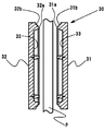
- FIG. 2 is a schematic cross-sectional view illustrating a blow molding machine used in the present embodiment.
- the blow molding machine includes a molding die 30 and an extrusion device (not shown) for supplying the parison P in a molten state.
- the mold 30 includes a pair of molds 31 and 32 that can be brought into and out of contact with each other. Formed on the opposing surfaces of the molds 31 and 32 are concave molding surfaces 33 that are symmetrical with each other. On each of the molding surfaces 33, irregularities corresponding to the shape of the resin tray 10 are formed, and the resin tray 10 is shaped along the molding surface 33. Further, annular pinch-off portions 31a and 32a are provided on the entire outer peripheral edge of the molding surface 33 of the molds 31 and 32, and notches 31b and 32b are formed on the outer peripheral sides of the pinch-off portions 31a and 32a. Yes.
- the molds 31 and 32 are conventionally known so that a blow pressure can be applied in a sealed space formed by the molds 31 and 32 when the molds 31 and 32 are clamped. No blow pin is installed.
- the extrusion apparatus (not shown) is a conventionally known type, and detailed description thereof is omitted, but the thermoplastic resin pellets charged from the hopper are melted and kneaded in the cylinder by the rotation of the screw by the hydraulic motor.
- the molten resin is transferred to the accumulator chamber and stored in a certain amount, and the molten resin is sent toward the head by driving the plunger, through a die gap formed by an annular space formed between the head die and the core.
- a continuous cylindrical parison P is extruded.
- the thermoplastic resin forming the resin tray 10 of the present invention has a sea-island structure in which polypropylene is dispersed in an island shape with respect to polyethylene, and the dispersion state has a cohesive peeling property at a parting line depending on the degree of kneading with a screw. Can be adjusted. That is, by decreasing the kneading degree of the thermoplastic resin, the polypropylene islands become large, and cohesive peeling at the parting line becomes easy.
- the die gap is arranged vertically downward, and the molten parison P extruded from the die gap is sent vertically downward in a form that hangs down from the die gap as it is, and a die 31 disposed below the die gap. 32 is arranged between them.
- FIG. 3 is a sectional view in the radial direction of the parison P when the molds 31 and 32 are opened
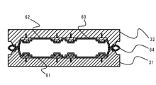
- FIG. 4 is a sectional view in the radial direction of the parison P when the molds 31 and 32 are clamped
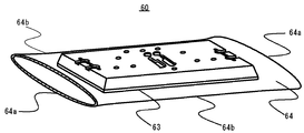
- FIG. 5 is a perspective view of the blow molded product 60 taken out from the molds 31 and 32
- FIG. 6 is a partial cross-sectional view of the blow molded product 60.
- thermoplastic resin material which is a mixture of polypropylene and polyethylene
- a thermoplastic resin material which is a mixture of polypropylene and polyethylene
- the molten cylindrical parison P is extruded at a predetermined extrusion speed so as to hang downward.
- the extruded cylindrical parison P is sequentially supplied between the molds 31 and 32 opened as shown in FIG. Thereby, according to the opening / closing timing of the dies 31, 32, a predetermined area (hereinafter referred to as a molding area) to be molded of the cylindrical parison P is positioned between the dies 31, 32.
- a predetermined area hereinafter referred to as a molding area
- the molding area is configured to be slightly larger than the area surrounded by the pinch-off portions 31a and 32a of the molds 31 and 32. That is, the diameter of the cylindrical parison P is slightly larger than the area surrounded by the pinch-off portions 31a and 32a, and the lower end of the cylindrical parison P is positioned below the pinch-off portions 31a and 32a.
- the molding region of the cylindrical parison P is crushed and held between the pinch-off portions 31a and 32a, and over the entire circumference of the pinch-off portions 31a and 32a.
- flash part 64 of the state which the parison P protruded outside is formed.
- FIG. 5 is a perspective view of the blow molded product 60.
- the blow molded product 60 is formed with a burr 64 along the parting line 63. Since the burr 64 is formed on the end side of the molding region of the cylindrical parison P, one end 64a that is substantially parallel to the radial direction of the parison P is open and substantially parallel to the axial direction. The other side end portion 64b has a bag shape.
- the blow molded product 60 shown in FIG. 5 shows the state separated from the parison P by a cutter or the like.
- FIG. 6 is a partial cross-sectional view of the blow molded product 60 from which the burr 64 is cut and removed.
- an internal hollow blow-molded product 60 in which the one side 61 corresponding to one mold 31 and the other side 62 corresponding to the other mold 32 are symmetrically joined to each other along the parting line 63. It becomes.
- the one side portion 61 and the other side portion 62 exhibit a shape that is plane-symmetric with respect to a plane that passes through the parting line 63.
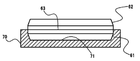
- FIG. 7 is an explanatory diagram illustrating a process of separating the blow molded product 60 into one side portion 61 and the other side portion 62.
- one side 61 of the blow molded product 60 is supported by the jig 70.
- a supporting recess 71 is formed on the upper surface of the jig 70.
- the supporting recess 71 has a shape that fits to the outer peripheral surface of the one side portion 61 of the blow molded product 60, and can hold the one side portion 61 with the other side portion 62 exposed.
- the upper end surface of the peripheral wall portion 12 of the resin tray 10 corresponding to the one side portion 61 and the upper end surface of the peripheral wall portion 12 of the resin tray 10 corresponding to the other side portion 62 part the blow molded product 60.
- the surface is peeled along the line P.
- the thermoplastic resin which is the material of the blow molded product 60, contains 5 to 50% by weight of polypropylene and 50 to 95% by weight of polyethylene, and has a sea-island structure in which polypropylene is an island and the polyethylene is the sea. ing.
- the one side part 61 and the other side part 62 of the blow molded product 60 are fused at the portion where the polypropylene and the polyethylene are in contact with each other, but are not fused at the portion where the polypropylene and the polyethylene are in contact with each other.
- the strength (fusion strength) is not so great. Thereby, the one side part 61 and the other side part 62 can be cohesively peeled along the parting line 63, and can be easily separated by an appropriate impact.
- the protrusions on the one side portion 61 and the other side portion 62 are located facing each other.
- the second protrusion 24 has the same height as the peripheral wall portion 12, and therefore, the top portions facing each other contact each other (see FIG. 6).
- the bonding strength of the top portion of the second protrusion 24 is not large due to the above-described sea-island structure, and can be easily agglomerated and peeled off.
- the first protrusions 21, 22, 23 and the minute protrusions 25 are lower than the peripheral wall part 12 and have a gap between the opposing top parts (see FIG. 4), they do not hinder peeling.
- Each of the resin trays 10 thus agglomerated and peeled has a rough surface in which the surface shape of the upper end surface 12 a of the peripheral wall portion 12 is rougher than the outer peripheral surface of the peripheral wall portion 12. For this reason, after peeling off, the end surface 28a of the peripheral wall 28 may be subjected to a flame treatment process to form a smooth surface. Similarly, the top of the second protrusion 24 may be subjected to flame treatment to form a smooth surface.
- the thermoplastic resin as the material is sequentially arranged in the molds 31 and 32 as the melted parison P, so that preheating for each molding is unnecessary.
- the productivity is better than the case of manufacturing by vacuum molding or press molding.
- the molding surfaces 33 of the molds 31 and 32 used in the present embodiment are provided with projections corresponding to the projections 21, 22, 23, 24, and 25.
- these protrusions are detachable from the molding surfaces 33 of the dies 31 and 32.
- the protrusion molds for forming the protrusions have shapes corresponding to the respective protrusions.
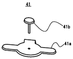
- 8 is an exploded perspective view of the projection mold 41 for forming the first projection 21
- FIG. 9 is an exploded perspective view of the projection mold 42 for forming the first projection 22.
- FIG. 4 is an exploded perspective view of a protrusion mold 43 for forming a first protrusion 23. Since the first protrusions 21, 22, 23 are provided with a truncated cone-shaped protrusion on a flat base, the protrusion molds 41, 42, 43 are flat plate members 41 a, 42 a corresponding to the base.
- a small hole is provided at substantially the center of the flat plate members 41a, 42a, and 43a, and a screw portion provided on the lower surface of the truncated cone portion of the truncated cone members 41b, 42b, and 43b can be inserted.
- FIG. 11 is a perspective view of a protrusion mold 44 for forming the second protrusion 24. Since the second projection 24 has a truncated cone shape, the projection mold 44 also has a truncated cone shape, and a screw portion is provided on the lower surface of the truncated cone portion. Although not shown in the drawing, since the minute protrusion 25 has a hemispherical shape, the protrusion mold for forming the minute protrusion has a hemispherical shape, and is formed on the lower surface of the hemispherical portion like the other protrusion molds. A threaded portion is provided.
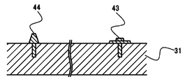
- FIG. 12 is a partially enlarged cross-sectional view of the state in which the projection molds 42 and 44 are attached to the mold 31. Thereby, the positions and shapes of the protrusions of the molds 31 and 32 can be freely changed, and various variations of trays can be easily manufactured.
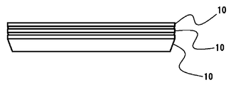
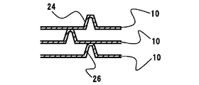
- the resin tray 10 of the present embodiment can be nested and stacked. 13 is a side view when the resin tray 10 is nested, and FIG. 14 is a partially enlarged sectional view thereof. 15 is a side view when the resin tray 10 is stacked, and FIG. 16 is a partially enlarged sectional view thereof.
- nesting refers to the storage or transport of empty trays, etc., when the trays are stacked in a state in which no objects are stored, and the tray directly above partially enters the tray immediately below.
- This is an aspect that enables space saving
- stacking is an aspect in which the stacked state is stabilized when the trays are stacked in a state in which the objects to be stored are stored.
- the nesting state will be described.
- back surface side recesses are provided at positions corresponding to the protrusions 21, 22, 23, 24, and 25.
- the peripheral wall portion 12 gradually expands to the outer peripheral side as the lower side portion moves upward from the bottom wall 11 side, the upper side portion is erected vertically on the lower side portion, and the upper end side is the bottom wall portion 11. It has a shape that expands to the outer peripheral side rather than the side.
- a predetermined nesting posture when a plurality of resin trays 10 are stacked in the same posture (hereinafter referred to as a predetermined nesting posture), the lower portion of the resin tray 10 positioned immediately above is loosely fitted to the resin tray 10 positioned immediately below. .
- a second protrusion 24 having a high height is provided on the bottom wall portion 11 of the resin tray 10, but a back surface-side recess corresponding to the second protrusion 24 is provided on the back surface of the bottom wall portion 11 of the resin tray 10. 26 is formed, and the second protrusion 24 is loosely fitted in the back surface recess 26 of the resin tray 10 immediately above.
- only the second projection 24 having a high height is loosely fitted in the concave portion 26 on the back surface (see FIG.
- the upper end surface of the second protrusion 24 is located at the same height as the upper end surface of the peripheral wall portion 12.
- the resin tray 10 directly above the resin tray 10 directly below is alternately superposed in a posture rotated 180 degrees in the horizontal direction (hereinafter referred to as a predetermined stacking posture)
- the resin tray 10 directly below is formed.
- the second protrusion 24 of the tray 10 is configured to support an area other than the back-side recess 26 corresponding to the second protrusion 24 of the resin tray 10 immediately above.
- the second protrusion 24 supports the outer peripheral side region of the back surface side concave portion corresponding to the minute protrusion 25 of the resin tray 10 immediately above.
- the second protrusion 24 of the resin tray 10 directly below is an outer peripheral side region of the recess on the back surface side of the resin tray 10 immediately above. And a space is formed between the resin tray 10 immediately below and the resin tray 10 directly above. Since the upper end surface of the second protrusion 24 is located at the same height as the upper end surface of the peripheral wall portion 12 and the region supported by the second protrusion 24 constitutes the lowermost surface of the resin tray 10, Thus, a sufficient space is formed between the resin tray 10 immediately below and the resin tray 10 immediately above. Thereby, a plurality of resin trays 10 can be stacked.
- the resin tray 10 can be switched between the nesting posture and the stacking posture by rotating in the horizontal direction, the convenience is improved.
- the space formed between adjacent resin trays 10 may be designed according to the size of the object to be stored, and at least the height when nesting is It should be lower than the height.
- the bottom wall portion of the tray into other shapes such as a circle, a square, or a polygon, and to make the peripheral wall portion into another shape.
- the function, shape and position of the protrusion formed on the upper surface of the bottom wall portion of the tray are not limited to the above embodiment, and can be changed as appropriate. What is necessary is just to design suitably the metal mold
- switching between nesting and stacking may be other than 180 degrees in the horizontal rotation angle.
- the horizontal rotation angle may be 90 degrees or other angles.
- the overall shape of the tray, the position of each protrusion, etc. are designed so that nesting and stacking are possible at the set rotation angle good.
Landscapes
- Engineering & Computer Science (AREA)
- Mechanical Engineering (AREA)
- Manufacturing & Machinery (AREA)
- Physics & Mathematics (AREA)
- Thermal Sciences (AREA)
- Ceramic Engineering (AREA)
- Containers Having Bodies Formed In One Piece (AREA)
- Stackable Containers (AREA)
- Blow-Moulding Or Thermoforming Of Plastics Or The Like (AREA)
- Moulds For Moulding Plastics Or The Like (AREA)
Abstract
本発明は、樹脂製トレイ、及び、その製造方法に関する発明であり、この樹脂製トレイを構成する材料は、島成分のポリプロピレンと海成分のポリエチレンとが所定の比率で海島構造を有しており、一方の金型(31)に対応する一方側部(61)と、他方の金型(32)に対応する他方側部(62)とがパーティングライン(63)に沿って接合した内部中空のブロー成形品(60)を作製し、次いでパーティングライン(63)に沿って剥離させると、一方側部(61)と他方側部(62)の各々が樹脂製トレイ(10)となるものである。樹脂製トレイが上記海島構造を有することによって、パーティングライン(63)に沿って容易に剥離でき、真空成形やプレス成形よりも高い生産性が得られる。
Description
本発明は、本発明はブロー成形により製造される樹脂製トレイ、及び、その樹脂製トレイの製造方法に関する。
樹脂製の収納トレイを製造する方法としては、金型上に樹脂製シートを配置し、加圧により樹脂製シートを金型の表面に沿った形状に賦形する真空成形やプレス成形が知られている。特許文献1は樹脂材料からなるトレイの従来例である。このトレイは、ポリプロピレン等の樹脂材料からなるシートを金型に形成したキャビティに吸引し、金型の成形面形状をシートに対して転写することにより真空成形する。
ところで、真空成形やプレス成形による製造方法では、樹脂製シートを金型上に配置した後に、成形に適する程度まで樹脂製シートを軟化させる予備加熱を行う。しかしながら、この予備加熱にはある程度の時間を要し、成形のたびに予備加熱を行う必要があるため、生産性が低かった。
本発明は、真空成形やプレス成形よりも高い生産性で製造可能なトレイ及びそのトレイの製造方法を提供することを目的とする。
本発明のトレイは、底壁部と、当該底壁部の周縁部から立ち上がる環状の周壁部とを備え、前記底壁部と前記周壁部とにより収納空間を形成する樹脂製トレイであって、前記樹脂製トレイを構成する樹脂はポリプロピレンが5~50重量%、ポリエチレンが50~95重量%含有され、当該ポリプロピレンを島部とし、当該ポリエチレンを海部とする海島構造を有する熱可塑性樹脂であり、前記周壁部の上端面は、一方の金型に対応する一方側部と他方の金型に対応する他方側部とがパーティングラインに沿って接合した内部中空のブロー成形品を、当該パーティングラインに沿って剥離した面であることを特徴とする。
この発明によれば、内部中空のブロー成形品をパーティングラインに沿って剥離すると、一方側部と他方側部とに分離し、二つの樹脂製トレイとなる。ブロー成形品は、一方の金型に対応する一方側部と他方の金型に対応する他方側部とがパーティングラインに沿って接合したものであるが、材料となる熱可塑性樹脂はポリプロピレンとポリエチレンが所定の比率で海島構造を構成しているため、接合強度はそれ程大きくなく、パーティングラインに沿って容易に凝集剥離可能である。このブロー成形品は、順次送り出される溶融状態の筒状のパリソンを、次々とブロー成形することで得られるため、真空成形やプレス成
形に必要な予備加熱は不要である。
形に必要な予備加熱は不要である。
本発明によれば、一つのブロー成形品から同時に二つのトレイが製造可能である。ブロー成形品は、順次送り出される溶融状態のパリソンから次々と成形できるため、成形ごとの予備加熱も不要である。このため真空成形やプレス成形の場合と比べて生産性が良好な樹脂製トレイ及び樹脂製トレイの製造方法を提供できる。
以下、添付図面を参照しながら本発明の一実施形態について説明する。図1は、本実施の形態の樹脂製樹脂製トレイ10の斜視図である。樹脂製トレイ10は、略平板状をなす底壁部11と、底壁部11の周縁部全周から上方に向かって立ち上がる環状の周壁部12とを具備し、底壁部11と周壁部12とにより囲まれる空間が収納空間を形成している。
底壁部11は、矩形の平板の四つの角部を切り欠いた形状を呈する。底壁部11の収納空間側の面(上面)には、所定の位置に複数の突起が設けられている。本実施の形態では、被収納物の凹部(図示せず)を勘合させて、被収納物を底壁部11に対して位置決めする第一突起21,22,23、複数の樹脂製トレイ10をスタッキングしたときに直上のトレイの底面を支持する第二突起24、及び、底壁部11の上面全体に所定間隔でマトリックス状に形成される微小突起25が設けられている。第一突起21,22,23及び微小突起25の上端は、周壁部12の上端面よりも高さが低く、第二突起24の上端は周壁部12の上端面と高さが略同じとなっている。
以下に、本発明の技術的思想を樹脂製トレイ10の製造方法を用いて説明する。図2は、本実施の形態で用いるブロー成形機を説明する概略断面図である。ブロー成形機は、成形型30と、溶融状態のパリソンPを供給する押出装置(図示せず)とを具備している。
成形型30は互いに接離可能な一対の金型31、32を備えている。金型31,32の対向面には互いに面対称をなす成形面33が凹設されている。成形面33の各々には、樹脂製トレイ10の形状に対応する凹凸が形成されており、この成形面33に沿って樹脂製トレイ10が賦形される。さらに金型31,32の成形面33の外周縁部全周には環状のピンチオフ部31a,32aが突設されており、ピンチオフ部31a,32aの外周側には切欠31b、32bが形成されている。
また、金型31,32には、金型31,32を型締したときに両金型31,32により形成される密閉空間内にブロー圧をかけることが可能なように、従来既知の図示しないブローピンが設置されている。
押出装置(図示せず)は、従来既知のタイプであり、その詳しい説明は省略するが、ホッパーから投入された熱可塑性の樹脂ペレットが、シリンダー内で油圧モータによるスクリューの回転により溶融、混練され、溶融状態の樹脂がアキュムレータ室に移送されて一定量貯留され、プランジャーの駆動によりヘッドに向けて溶融樹脂が送られ、ヘッドのダイとコアの間に形成された環状空間からなるダイギャップを通じて連続的な筒状のパリソンPが押し出される。尚、本発明の樹脂製トレイ10を形成する熱可塑性樹脂はポリエチレンに対してポリプロピレンが島状に分散した海島構造からなり、その分散状態をスクリューによる混練度合によってパーティングラインでの凝集剥離性を調整することができる。つまり、熱可塑性樹脂の混練度合を低下させることによりポリプロピレンの島が大きくなりパーティングラインにおける凝集剥離が容易となる。
ダイギャップは、鉛直下向きに配置され、ダイギャップから押し出された溶融状態のパリソンPは、そのままダイギャップから垂下する形態で、鉛直下向きに送られ、ダイギャップの下方に配される金型31,32の間に配置されるようになっている。
以上の構成のブロー成形機を用いた樹脂製トレイ10の製造方法を説明する。図3は、金型31,32を型開きしたときの、パリソンPの径方向における断面図、図4は、金型31,32を型締めしたときの、パリソンPの径方向における断面図、図5は、金型31,32から取り出されたブロー成形品60の斜視図、図6は、ブロー成形品60の一部断面図である。
まず、ポリプロピレンとポリエチレンの混合物である熱可塑性樹脂材料を溶融状態として押出装置に貯留する。そして、貯留された熱可塑性樹脂を単位時間当たり所定押出量で間欠的にダイギャップから押し出すことにより、溶融状態の筒状のパリソンPを下方に垂下するように所定押出速度で押し出す。押し出された筒状のパリソンPは、図3に示すように、型開きされた金型31,32の間に順次供給される。これにより、金型31,32の開閉のタイミングに合わせて、筒状のパリソンPの成形対象となる所定領域(以下、被成形領域という。)が金型31,32の間に位置することとなる。
つぎに、図4に示すように、金型31,32を型締めする。被成形領域は、金型31,32のピンチオフ部31a,32aに囲まれる領域よりも一回り大きく構成されている。すなわち、筒状のパリソンPの径はピンチオフ部31a,32aに囲まれる領域よりも一回り大きく、また、筒状のパリソンPの下端はピンチオフ部31a,32aよりも下方に位置している。これにより、金型31,32を型締めすると、筒状のパリソンPの被成形領域は押し潰されてピンチオフ部31a,32aにより狭持されるとともに、ピンチオフ部31a,32aの全周に渡ってパリソンPが外側にはみ出した状態のバリ部64が形成される。
この状態において、パリソンPのピンチオフ部31a,32aにより密封された内部にブローピン(図示略)を介して空気を注入し、この空気圧によってパリソンPを膨張させて金型31,32の成形面33に密着させる。これにより、パリソンPは金型31,32の各成形面と相補関係の形状に成形される。そしてパリソンPが冷却固化した後に金型31と金型32を型開きし、中空体からなるブロー成形品60を金型31と金型32の間から取り出す。
図5は、ブロー成形品60の斜視図である。ブロー成形品60には、パーティングライン63に沿ってバリ部64が形成されている。バリ部64は、筒状のパリソンPの被成形領域の端部側に形成されるため、パリソンPの径方向に略平行な一方側端部64aは開口しており、軸方向に略平行な他方側端部64bは袋状となっている。なお、図5に示すブロー成形品60は、パリソンPからカッター等により切り離した状態を示すものである。
つぎに、ブロー成形品60から、カッター等によってバリ部64を切断除去する。図6は、バリ部64が切断除去されたブロー成形品60の一部断面図である。これにより、一方の金型31に対応する一方側部61と他方の金型32に対応する他方側部62とが互いに対称形状でパーティングライン63に沿って接合した内部中空のブロー成形品60となる。一方側部61と他方側部62とは、パーティングライン63を通る平面に対して面対称な形状を呈する。
図7は、ブロー成形品60を一方側部61と他方側部62に分離させる工程を説明する説明図である。まず、ブロー成形品60の一方側部61を治具70で支持する。治具70の上面には支持用凹部71が形成してある。この支持用凹部71はブロー成形品60の一方側部61の外周面に嵌合する形状であり、他方側部62が露出した状態で一方側部61を保持可能となっている。
この治具70の支持用凹部71にブロー成形品60の一方側部61を嵌合した上で、他方側部62に対してハンマー(図示略)等によって衝撃を加える。この衝撃がブロー成形品60のパーティングライン63に加わると、ブロー成形品60がパーティングライン63に沿って剥離し、一方側部61と他方側部62に分離する。分離した一方側部61と他方側部62は各々が樹脂製トレイ10を構成し、一つの成形品60から図1に示すような同形状の樹脂製トレイ10が二つ製造されることとなる。すなわち、一方側部61に相当する樹脂製トレイ10の周壁部12の上端面、及び、他方側部62に相当する樹脂製トレイ10の周壁部12の上端面は、ブロー成形品60をパーティングラインPに沿って剥離した面となる。
ここで、ブロー成形品60の材料である熱可塑性樹脂は、ポリプロピレンが5~50重量%、ポリエチレンが50~95重量%含有され、ポリプロピレンを島部とし、当該ポリエチレンを海部とする海島構造となっている。このため、ブロー成形品60の一方側部61と他方側部62は、ポリプロピレン同士及びポリエチレン同士が接する部分では融着しているものの、ポリプロピレンとポリエチレンが接する部分では融着しておらず、接合強度(融着強度)はそれほど大きくない。これにより、一方側部61と他方側部62はパーティングライン63に沿って凝集剥離可能であり、適当な衝撃により簡単に分離することとなる。
また、ブロー成形品60の内部空間は、一方側部61と他方側部62の各突起が互いに対向して位置している。複数の突起のうち第二突起24は、周壁部12と高さが同じであるため対向する頂部同士が接触する(図6参照)。しかしながら、第二突起24の頂部についても上述の海島構造により接合強度は大きくなく、容易に凝集剥離可能となっている。一方、第一突起21,22,23及び微小突起25は周壁部12よりも高さが低く、対向する頂部同士の間に隙間を有するため(図4参照)、剥離を阻害することはない。
このようにして凝集剥離させた各樹脂製トレイ10は、周壁部12の上端面12aの表面形状が、周壁部12の外周面よりも粗い粗面となる。このため、剥離した後に、周壁部28の端面28aに対して火炎処理加工を施し、平滑面としてもよい。第二突起24の頂部についても、同様に火炎処理加工を施して平滑面としても良い。
このように本実施形態の樹脂製トレイ10の製造方法においては、材料である熱可塑性樹脂が溶融状態のパリソンPとして次々と金型31,32に配置されるため、成形ごとの予備加熱は不要であり、又、一回の成形によって二つの樹脂製トレイ10を同時に製造可能であるため、真空成形やプレス成形で製造する場合と比べて生産性が良好である。
また、本実施の形態の樹脂製トレイ10の製造方法では、底壁部11に設けられる突起21,22,23,24,25の形状や位置の変更が容易となっている。このため、図2や図4に示されるように、本実施の形態で使用される金型31,32の成形面33には、突起21,22,23,24,25に対応する突起が設けられているが、これらの突起は金型31,32の成形面33から着脱可能となっている。
本実施の形態では、第一突起21,22,23は形状の異なる三種類の突起であることから、突起を形成するための突起用金型も各々に対応する形状のものが用いられる。図8は第一突起21を形成するための突起用金型41の分解斜視図であり、図9は第一突起22を形成するための突起用金型42の分解斜視図であり、図10は第一突起23を形成するための突起用金型43の分解斜視図である。第一突起21,22,23は、平板状の土台の上に円錐台形状の突起が設けられていることから、突起用金型41,42,43は土台に対応する平板状部材41a,42a,43aと、円錐台形状の突起に対応する円錐台部材41b,42b,43bを備える。平板状部材41a,42a,43aの略中央には小孔が設けられおり、円錐台部材41b,42b,43bの円錐台部の下面に設けられるネジ部が挿通可能となっている。
図11は第二突起24を形成するための突起用金型44の斜視図である。第二突起24は円錐台形状であるため、突起用金型44も円錐台形状であり、円錐台部の下面にネジ部が設けられている。また、図は省略するが、微小突起25は半球形状であるため、微小突起を形成するための突起用金型も半球形状であり、他の突起用金型と同様に半球形状部の下面にネジ部が設けられている。
また、二つの金型31,32の成形面には、複数のネジ孔(図示省略)がマトリックス状に設けられており、これらの突起用金型は、このネジ孔にネジ部を螺合させることで取付可能となっている。図12は、突起用金型42,44を金型31に取り付けた状態の一部拡大断面図である。これにより、金型31,32の突起の位置や形状を自在に変更でき、様々なバリエーションのトレイが容易に製造可能となる。
また、本実施の形態の樹脂製トレイ10は、ネスティングとスタッキングが可能となっている。図13は樹脂製トレイ10をネスティングしたときの側面図であり、図14はその一部拡大断面図である。また、図15は樹脂製トレイ10をスタッキングしたときの側面図であり、図16はその一部拡大断面図である。
なお、ここでネスティングとは、被収納物が収納されていない状態においてトレイを積み上げたときに、直上のトレイが直下のトレイの中に一部入り込むことで、空のトレイの保存や搬送等において省スペース化を可能とする態様であり、スタッキングとは、被収納物が収納された状態においてトレイを積み上げたときに、積み上げ状態が安定する態様である。
まず、ネスティング状態について説明する。樹脂製トレイ10の底壁部11裏面には、各突起21,22,23,24,25に対応する位置に裏面側凹部が設けられている。また、周壁部12は、下側部が底壁11側から上方に向かうにつれて外周側に徐々に拡がり、下側部の上に上側部が垂直に立設されており、上端側が底壁部11の側よりも外周側に拡がった形状を呈している。
このため、複数の樹脂製トレイ10を同一姿勢(以下、所定のネスティング姿勢という。)で重ね合わせると、直上に位置する樹脂製トレイ10の下部が直下に位置する樹脂製トレイ10に遊嵌する。樹脂製トレイ10の底壁部11には高さの高い第二突起24が設けられているが、樹脂製トレイ10の底壁部11の裏面には、第二突起24に対応する裏面側凹部26が形成されており、第二突起24は直上の樹脂製トレイ10の裏面凹部26に遊嵌する。なお、本実施の形態では、高さの高い第二突起24のみが裏面側凹部26に遊嵌し(図14参照)、高さの低い他の突起21,22,23,25は直上の樹脂製トレイ10の裏面に達することなく下方に位置することとなる。このように構成することで、複数の樹脂製トレイ10をネスティングすると、スタッキングしたときよりも高さが低くなり、空の樹脂製トレイ10の搬送や収納等において省スペース化が図られる。
つぎに、スタッキング状態について説明する。第二突起24の上端面は周壁部12の上端面と同じ高さに位置している。また、直下の樹脂製トレイ10に対して直上の樹脂製トレイ10を水平方向に180度回転させた姿勢(以下、所定のスタッキング姿勢という。)で交互に重ね合わせたときに、直下の樹脂製トレイ10の第二突起24が、直上の樹脂製トレイ10の第二突起24に対応する裏面側凹部26以外の領域を支持する構成となっている。本実施の形態では、第二突起24は、直上の樹脂製トレイ10の微小突起25に対応する裏面側凹部の外周側領域を支持している。
このため、樹脂製トレイ10に被収納物を収納し、所定のスタッキング姿勢で重ね合わせると、直下の樹脂製トレイ10の第二突起24が直上の樹脂製トレイ10の裏面側凹部の外周側領域を支持し、直下の樹脂製トレイ10と直上の樹脂製トレイ10との間に空間を形成する。第二突起24の上端面は周壁部12の上端面と同じ高さに位置しており、且つ、第二突起24が支持する領域は樹脂製トレイ10の最下面を構成しているため、直上の樹脂製トレイ10が直下の樹脂製トレイ10に入り込むことなく、直下の樹脂製トレイ10と直上の樹脂製トレイ10との間に十分な空間が形成される。これにより、複数の樹脂製トレイ10をスタッキング可能となる。
このように、本実施の形態によれば、樹脂製トレイ10を水平方向に回転させることでネスティング姿勢とスタッキング姿勢に切り替えることができるため、利便性が向上する。
なお、ネスティングやスタッキングにおいて、隣接する樹脂製トレイ10の間に形成される空間は、被収納物の大きさ等に合わせて設計すれば良く、少なくともネスティングしたときの高さが、スタッキングしたときの高さよりも低ければ良い。
以上、本発明を適用した実施形態について説明してきたが、本発明が前述の実施形態に限られるものでないことは言うまでもなく、本発明の要旨を逸脱しない範囲において、種々の変更を加えることが可能である。
たとえば、トレイの底壁部を円形や正方形や多角形等の他の形状としたり、周壁部を他の形状としたりすることも可能である。
また、トレイの底壁部上面に形成される突起の機能や形状や位置についても、上記実施の形態に限定されるものではなく、適宜変更可能である。二つの金型に取り付けられる突起用金型は、底壁部上面の各突起に応じて適宜設計すれば良い。
また、ネスティングとスタッキングの切り替えは、水平方向の回転角が180度以外でも良い。たとえば、水平方向の回転角が90度やその他の角度でも良く、この場合は、設定した回転角でネスティングとスタッキングが可能となるように、トレイの全体形状や各突起の位置等を設計すれば良い。
10 樹脂製トレイ
11 底壁部
12 周壁部
21,22,23 第一突起
24 第二突起
25 微小突起
26 第二突起に対応する裏面側凹部
30 成形型
31,32 金型
31a,32a ピンチオフ部
41,42,43,44,45 突起用金型
60 ブロー成形品
61 一方側金型に対応する一方側部
62 他方側金型に対応する他方側部
63 パーティングライン
64 バリ部
70 治具
P パリソン
11 底壁部
12 周壁部
21,22,23 第一突起
24 第二突起
25 微小突起
26 第二突起に対応する裏面側凹部
30 成形型
31,32 金型
31a,32a ピンチオフ部
41,42,43,44,45 突起用金型
60 ブロー成形品
61 一方側金型に対応する一方側部
62 他方側金型に対応する他方側部
63 パーティングライン
64 バリ部
70 治具
P パリソン
Claims (7)
- 底壁部と、当該底壁部の周縁部から立ち上がる環状の周壁部とを備え、前記底壁部と前記周壁部とにより収納空間を形成する樹脂製トレイであって、
前記樹脂はリプロピレンが5~50重量%、ポリエチレンが50~95重量%含有さ」れ、当該ポリプロピレンを島部とし、当該ポリエチレンを海部とする海島構造を有する熱可塑性樹脂であり、
前記周壁部の上端面は、一方の金型に対応する一方側部と他方の金型に対応する他方側部とがパーティングラインに沿って接合した内部中空のブロー成形品を、当該パーティングラインに沿って剥離した面であることを特徴とする樹脂製トレイ。 - 前記底壁部の収納空間側の面には、前記周壁部よりも高さの低い第一突起が形成されていることを特徴とする請求項1記載の樹脂製トレイ。
- 前記周壁部の上端面の表面形状は、前記周壁部の外周面よりも粗い粗面であることを特徴とする請求項1又は請求項2に記載のトレイ。
- 前記周壁部の上端面は、火炎処理加工により平滑面とされていることを特徴とする請求項1又は請求項2に記載のトレイ。
- 前記周壁部は上端側が前記底壁部側よりも外周側に拡がっており、
前記底壁部の収納空間側の面に複数の第ニ突起が設けられ、
前記底壁部の裏面の前記第ニ突起と対応する位置には複数の裏面側凹部が設けられており、
直下の前記樹脂製トレイと直上の前記樹脂製トレイを同一姿勢で重ね合わせると、直下の前記樹脂製トレイの第ニ突起が直上の前記樹脂製トレイの前記裏面側凹部に遊嵌してネスティング状態となり、
直下の前記樹脂製トレイに対して直上の前記樹脂製トレイを水平方向に所定角度回転させた姿勢で交互に重ね合わせると、直下の前記樹脂製トレイの前記第二突起が直上の前記トレイの前記底壁部の前記裏面凹部以外の領域を支持してスタッキング状態となることを特徴とする前記請求項1乃至請求項4のいずれか一項に記載の樹脂製トレイ。 - 底壁部と、当該底壁部の周縁部から立ち上がる環状の周壁部とを備え、前記底壁部と前記周壁部とにより収納空間を形成する樹脂製トレイの製造方法であって、
ポリプロピレンが5~50重量%、ポリエチレンが50~95重量%含有され、当該ポリプロピレンを島部とし、当該ポリエチレンを海部とする海島構造を有する筒状のパリスンを送り出して、当該パリスンの所定領域を一対の金型の間に配置するステップと、
一対の前記金型を型締めして、前記パリソンの前記所定領域を前記金型のピンチオフ部で狭持し、前記ピンチオフ部の全外周に前記パリスンがはみ出した状態のバリ部を形成するステップと、
前記型締めされた一対の前記金型内に位置する前記パリソンの内部に気体を供給し、前記バリ部に沿ってパーティングラインが形成された内部中空のブロー成形品を成形するステップと、
前記金型から取り出された前記ブロー成形品から前記バリ部を切断除去するステップと、
前記バリ部が切断除去されたブロー成形品を前記パーティングラインに沿って剥離することで、当該剥離面が前記周壁部の上端面となる前記樹脂製トレイを得るステップと、
を備えることを特徴とする樹脂製トレイの製造方法。 - 前記パーティングラインに沿って剥離した剥離面に火炎処理を施して平滑面とするステップを備えることを特徴とする請求項6記載のトレイの製造方法。
Applications Claiming Priority (2)
| Application Number | Priority Date | Filing Date | Title |
|---|---|---|---|
| JP2015031353A JP6485690B2 (ja) | 2015-02-20 | 2015-02-20 | 樹脂製トレイ、及び、樹脂製トレイの製造方法 |
| JP2015-031353 | 2015-02-20 |
Publications (1)
| Publication Number | Publication Date |
|---|---|
| WO2016133221A1 true WO2016133221A1 (ja) | 2016-08-25 |
Family
ID=56689394
Family Applications (1)
| Application Number | Title | Priority Date | Filing Date |
|---|---|---|---|
| PCT/JP2016/055007 Ceased WO2016133221A1 (ja) | 2015-02-20 | 2016-02-22 | 樹脂製トレイ、及び、樹脂製トレイの製造方法 |
Country Status (2)
| Country | Link |
|---|---|
| JP (1) | JP6485690B2 (ja) |
| WO (1) | WO2016133221A1 (ja) |
Citations (5)
| Publication number | Priority date | Publication date | Assignee | Title |
|---|---|---|---|---|
| JPS62165209U (ja) * | 1986-04-11 | 1987-10-20 | ||
| JP2011025696A (ja) * | 2009-06-30 | 2011-02-10 | Kyoraku Co Ltd | ブロー成形用金型およびブロー成形方法 |
| JP2012066871A (ja) * | 2010-09-27 | 2012-04-05 | Kyoraku Co Ltd | 樹脂製パレット |
| JP2012096811A (ja) * | 2010-10-29 | 2012-05-24 | Sekisui Plastics Co Ltd | 搬送用トレイ |
| JP2015137130A (ja) * | 2014-01-23 | 2015-07-30 | 凸版印刷株式会社 | 包装袋 |
-
2015
- 2015-02-20 JP JP2015031353A patent/JP6485690B2/ja active Active
-
2016
- 2016-02-22 WO PCT/JP2016/055007 patent/WO2016133221A1/ja not_active Ceased
Patent Citations (5)
| Publication number | Priority date | Publication date | Assignee | Title |
|---|---|---|---|---|
| JPS62165209U (ja) * | 1986-04-11 | 1987-10-20 | ||
| JP2011025696A (ja) * | 2009-06-30 | 2011-02-10 | Kyoraku Co Ltd | ブロー成形用金型およびブロー成形方法 |
| JP2012066871A (ja) * | 2010-09-27 | 2012-04-05 | Kyoraku Co Ltd | 樹脂製パレット |
| JP2012096811A (ja) * | 2010-10-29 | 2012-05-24 | Sekisui Plastics Co Ltd | 搬送用トレイ |
| JP2015137130A (ja) * | 2014-01-23 | 2015-07-30 | 凸版印刷株式会社 | 包装袋 |
Also Published As
| Publication number | Publication date |
|---|---|
| JP6485690B2 (ja) | 2019-03-20 |
| JP2016153314A (ja) | 2016-08-25 |
Similar Documents
| Publication | Publication Date | Title |
|---|---|---|
| KR20130038281A (ko) | 블로 성형 공구 및 압출 블로 성형된 플라스틱 제품의 제조 방법 | |
| KR20100103523A (ko) | 열가소체로 이루어진 용기를 제조하기 위한 방법 및 장치와 이에 의해 제조된 용기 | |
| EP3228437B1 (en) | Device for producing hollow container | |
| RU2019111175A (ru) | Сонотрод и опора для ультразвуковой сварки пластиков, способ изготовления пластикового контейнера | |
| CN110087518B (zh) | 双壁容器的改进 | |
| JP2012254819A (ja) | プラスチック成形体 | |
| EP2969471B2 (en) | Multifunctional detabber apparatus and method | |
| JP6078257B2 (ja) | 二重容器、二重容器成形用プリフォーム、及び二重容器の製造方法 | |
| JP6485690B2 (ja) | 樹脂製トレイ、及び、樹脂製トレイの製造方法 | |
| CN108136655B (zh) | 多室容器的制造装置及其制造方法 | |
| JP2011073422A (ja) | 成形方法 | |
| JP2013208776A (ja) | 二重容器の製造方法 | |
| JP5332040B2 (ja) | ブローフィルシール用成形金型 | |
| JP6714073B2 (ja) | プラスチック材料のブロー成形によるフランジ付き大容量容器の製造方法および装置 | |
| WO2019146701A1 (ja) | 樹脂製の容器部品の製造方法、金型ユニットおよびそれを備えるブロー成形機 | |
| JP2008308217A (ja) | 容器 | |
| EP3900912B1 (en) | Resin-made container, resin-made container manufacturing method, resin-made container manufacturing apparatus, and metal mold | |
| JP2005280757A (ja) | スタック性能を有するカップ状容器 | |
| WO2012161150A1 (ja) | プリフォーム、合成樹脂製の吊り具付容器、及び吊り具付容器の成形方法 | |
| WO2018062034A1 (ja) | 金型及びその製造方法、並びに成形体の製造方法 | |
| JP6875637B2 (ja) | 構造体及び製造方法 | |
| JP2019177564A (ja) | ブロー成形体の製造装置及び製造方法 | |
| US7713055B2 (en) | Blow mold assembly | |
| JP5833915B2 (ja) | 植物培養ポット及びその製造方法 | |
| JP6985591B2 (ja) | 樹脂製パネル及び製造方法 |
Legal Events
| Date | Code | Title | Description |
|---|---|---|---|
| 121 | Ep: the epo has been informed by wipo that ep was designated in this application |
Ref document number: 16752607 Country of ref document: EP Kind code of ref document: A1 |
|
| NENP | Non-entry into the national phase |
Ref country code: DE |
|
| 122 | Ep: pct application non-entry in european phase |
Ref document number: 16752607 Country of ref document: EP Kind code of ref document: A1 |