WO2016133026A1 - 排気浄化システム及びその制御方法 - Google Patents
排気浄化システム及びその制御方法 Download PDFInfo
- Publication number
- WO2016133026A1 WO2016133026A1 PCT/JP2016/054200 JP2016054200W WO2016133026A1 WO 2016133026 A1 WO2016133026 A1 WO 2016133026A1 JP 2016054200 W JP2016054200 W JP 2016054200W WO 2016133026 A1 WO2016133026 A1 WO 2016133026A1
- Authority
- WO
- WIPO (PCT)
- Prior art keywords
- maf
- intake air
- nox
- exhaust
- air amount
- Prior art date
- Legal status (The legal status is an assumption and is not a legal conclusion. Google has not performed a legal analysis and makes no representation as to the accuracy of the status listed.)
- Ceased
Links
Images





Classifications
-
- B—PERFORMING OPERATIONS; TRANSPORTING
- B01—PHYSICAL OR CHEMICAL PROCESSES OR APPARATUS IN GENERAL
- B01D—SEPARATION
- B01D53/00—Separation of gases or vapours; Recovering vapours of volatile solvents from gases; Chemical or biological purification of waste gases, e.g. engine exhaust gases, smoke, fumes, flue gases, aerosols
- B01D53/34—Chemical or biological purification of waste gases
- B01D53/92—Chemical or biological purification of waste gases of engine exhaust gases
- B01D53/94—Chemical or biological purification of waste gases of engine exhaust gases by catalytic processes
-
- F—MECHANICAL ENGINEERING; LIGHTING; HEATING; WEAPONS; BLASTING
- F01—MACHINES OR ENGINES IN GENERAL; ENGINE PLANTS IN GENERAL; STEAM ENGINES
- F01N—GAS-FLOW SILENCERS OR EXHAUST APPARATUS FOR MACHINES OR ENGINES IN GENERAL; GAS-FLOW SILENCERS OR EXHAUST APPARATUS FOR INTERNAL-COMBUSTION ENGINES
- F01N3/00—Exhaust or silencing apparatus having means for purifying, rendering innocuous, or otherwise treating exhaust
- F01N3/08—Exhaust or silencing apparatus having means for purifying, rendering innocuous, or otherwise treating exhaust for rendering innocuous
-
- F—MECHANICAL ENGINEERING; LIGHTING; HEATING; WEAPONS; BLASTING
- F01—MACHINES OR ENGINES IN GENERAL; ENGINE PLANTS IN GENERAL; STEAM ENGINES
- F01N—GAS-FLOW SILENCERS OR EXHAUST APPARATUS FOR MACHINES OR ENGINES IN GENERAL; GAS-FLOW SILENCERS OR EXHAUST APPARATUS FOR INTERNAL-COMBUSTION ENGINES
- F01N3/00—Exhaust or silencing apparatus having means for purifying, rendering innocuous, or otherwise treating exhaust
- F01N3/08—Exhaust or silencing apparatus having means for purifying, rendering innocuous, or otherwise treating exhaust for rendering innocuous
- F01N3/10—Exhaust or silencing apparatus having means for purifying, rendering innocuous, or otherwise treating exhaust for rendering innocuous by thermal or catalytic conversion of noxious components of exhaust
- F01N3/18—Exhaust or silencing apparatus having means for purifying, rendering innocuous, or otherwise treating exhaust for rendering innocuous by thermal or catalytic conversion of noxious components of exhaust characterised by methods of operation; Control
- F01N3/20—Exhaust or silencing apparatus having means for purifying, rendering innocuous, or otherwise treating exhaust for rendering innocuous by thermal or catalytic conversion of noxious components of exhaust characterised by methods of operation; Control specially adapted for catalytic conversion
-
- F—MECHANICAL ENGINEERING; LIGHTING; HEATING; WEAPONS; BLASTING
- F01—MACHINES OR ENGINES IN GENERAL; ENGINE PLANTS IN GENERAL; STEAM ENGINES
- F01N—GAS-FLOW SILENCERS OR EXHAUST APPARATUS FOR MACHINES OR ENGINES IN GENERAL; GAS-FLOW SILENCERS OR EXHAUST APPARATUS FOR INTERNAL-COMBUSTION ENGINES
- F01N3/00—Exhaust or silencing apparatus having means for purifying, rendering innocuous, or otherwise treating exhaust
- F01N3/08—Exhaust or silencing apparatus having means for purifying, rendering innocuous, or otherwise treating exhaust for rendering innocuous
- F01N3/10—Exhaust or silencing apparatus having means for purifying, rendering innocuous, or otherwise treating exhaust for rendering innocuous by thermal or catalytic conversion of noxious components of exhaust
- F01N3/24—Exhaust or silencing apparatus having means for purifying, rendering innocuous, or otherwise treating exhaust for rendering innocuous by thermal or catalytic conversion of noxious components of exhaust characterised by constructional aspects of converting apparatus
-
- F—MECHANICAL ENGINEERING; LIGHTING; HEATING; WEAPONS; BLASTING
- F02—COMBUSTION ENGINES; HOT-GAS OR COMBUSTION-PRODUCT ENGINE PLANTS
- F02D—CONTROLLING COMBUSTION ENGINES
- F02D41/00—Electrical control of supply of combustible mixture or its constituents
- F02D41/02—Circuit arrangements for generating control signals
- F02D41/04—Introducing corrections for particular operating conditions
-
- F—MECHANICAL ENGINEERING; LIGHTING; HEATING; WEAPONS; BLASTING
- F02—COMBUSTION ENGINES; HOT-GAS OR COMBUSTION-PRODUCT ENGINE PLANTS
- F02D—CONTROLLING COMBUSTION ENGINES
- F02D41/00—Electrical control of supply of combustible mixture or its constituents
- F02D41/20—Output circuits, e.g. for controlling currents in command coils
Definitions
- the present invention relates to an exhaust purification system and a control method thereof.
- a NOx occlusion reduction type catalyst is known as a catalyst for reducing and purifying nitrogen compounds (NOx) in exhaust gas discharged from an internal combustion engine.
- NOx nitrogen compounds
- This NOx occlusion reduction type catalyst occludes NOx contained in the exhaust when the exhaust is in a lean atmosphere, and reduces and purifies NOx occluded by hydrocarbons contained in the exhaust when the exhaust is in a rich atmosphere. Detoxify and release. For this reason, when the NOx occlusion amount of the catalyst reaches a predetermined amount, so-called NOx purge that makes the exhaust rich by post injection or exhaust pipe injection needs to be performed periodically to restore the NOx occlusion capacity ( For example, see Patent Document 1).
- An object of the present disclosure is to make it possible to perform injection system control in a state in which the amount of intake air is sufficiently reduced.
- An exhaust purification system of the present disclosure includes a NOx reduction catalyst that is provided in an exhaust passage of an internal combustion engine and stores NOx in exhaust when the exhaust air-fuel ratio is lean, and an intake air amount that detects an intake air amount of the internal combustion engine
- the exhaust air-fuel ratio is switched from the lean state to the rich state by using a sensor, air system control for reducing the intake air amount, and injection system control for increasing the fuel injection amount, thereby reducing and purifying the stored NOx.
- a controller that releases the NOx reduction catalyst from the NOx reduction catalyst wherein the controller includes a first difference value between the lean target first target intake air amount and the rich target second target intake air amount;
- the start timing of the injection system control is determined based on the ratio of the second difference value between the first target intake air amount and the intake air amount.
- An exhaust purification system of the present disclosure includes a NOx reduction catalyst that is disposed in an exhaust passage of an internal combustion engine, and stores NOx contained in the exhaust when the exhaust discharged from the internal combustion engine is in a lean state.
- the air-fuel ratio of the exhaust gas is controlled by using an intake air amount sensor for detecting the intake air amount of the internal combustion engine, an air system control for controlling the intake air amount, and an injection system control for controlling the fuel injection amount.
- An exhaust purification system comprising: a control unit that operates to perform the following process: Catalyst regeneration that switches the air-fuel ratio of the exhaust gas from a lean state to a rich state by executing the air system control and the injection system control, and releases NOx stored in the NOx reduction catalyst from the NOx reduction catalyst processing; A calculation process for calculating a second difference value that is a difference between a first target intake air amount that is a target intake air amount when the air-fuel ratio of the exhaust gas is in a lean state and an intake air amount of the internal combustion engine; A ratio between a first difference value that is a difference between one target intake air amount and a second target intake air amount that is a target intake air amount when the air-fuel ratio of the exhaust gas is in a rich state, and the second difference value
- the determination process which determines the start time of the said injection system control based on this.
- An exhaust purification system control method is provided in an exhaust passage of an internal combustion engine, and stores NOx contained in the exhaust when the exhaust discharged from the internal combustion engine is in a lean state.
- a control method for an exhaust purification system comprising: an air system control for controlling an intake air amount and an injection system control for controlling a fuel injection amount to change the air-fuel ratio of the exhaust from a lean state to a rich state
- a catalyst regeneration process for switching and releasing NOx stored in the NOx reduction catalyst from the NOx reduction catalyst; a first target intake air amount that is a target intake air amount when the air-fuel ratio of the exhaust is in a lean state
- a calculation process for calculating a second difference value which is a difference between the intake air amount of the internal combustion engine and the first target intake air amount and the air-fuel ratio of the exhaust is in a rich state
- a first difference value that is the difference between the second target intake air amount is an intake air quantity, on the basis of a ratio between the second difference value, including the determination process determines
- the injection system control can be performed in a state where the intake air amount is sufficiently reduced.
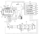
- FIG. 1 is an overall configuration diagram showing an exhaust purification system according to the present embodiment.
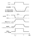
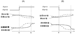
- FIG. 2 is a timing chart for explaining the NOx purge control according to the present embodiment.
- FIG. 3 is a block diagram showing a MAF target value setting process during NOx purge lean control according to the present embodiment.
- FIG. 4 is a block diagram showing a target injection amount setting process during NOx purge rich control according to the present embodiment.
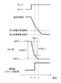
- FIG. 5 is a diagram schematically illustrating the processing of the injection system control start determination unit according to the present embodiment.
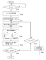
- FIG. 6 is a flowchart for explaining the switching from the lean state to the rich state of the MAF tracking control according to the present embodiment.
- FIG. 7 is a flowchart for explaining switching from the rich state to the lean state of the MAF tracking control according to the present embodiment.
- FIG. 8 is a diagram for explaining the difference between the actual MAF value and the MAF target value when shifting from the lean state to the rich state or from the rich state to the lean state.
- FIG. 9 is a block diagram showing the injection amount learning correction processing of the injector according to the present embodiment.
- FIG. 10 is a flowchart for explaining the learning correction coefficient calculation processing according to the present embodiment.
- FIG. 11 is a block diagram showing the MAF correction coefficient setting process according to the present embodiment.
- each cylinder of a diesel engine (hereinafter simply referred to as an engine) 10 is provided with an injector 11 that directly injects high-pressure fuel accumulated in a common rail (not shown) into each cylinder.
- the fuel injection amount and fuel injection timing of each injector 11 are controlled in accordance with an instruction signal input from an electronic control unit (hereinafter referred to as ECU) 50.
- ECU electronice control unit
- An intake passage 12 for introducing fresh air is connected to the intake manifold 10A of the engine 10, and an exhaust passage 13 for connecting exhaust to the outside is connected to the exhaust manifold 10B.
- an air cleaner 14 an intake air amount sensor (hereinafter referred to as MAF sensor) 40, a compressor 20A of the variable displacement supercharger 20, an intercooler 15, an intake throttle valve 16 and the like are provided in order from the intake upstream side.
- MAF sensor 40 intake air amount sensor
- the exhaust passage 13 is provided with a turbine 20B of the variable displacement supercharger 20, an exhaust aftertreatment device 30 and the like in order from the exhaust upstream side.
- An engine speed sensor 41, an accelerator opening sensor 42, and a boost pressure sensor 46 are attached to the engine 10.
- the EGR (Exhaust Gas Recirculation) device 21 includes an EGR passage 22 that connects the exhaust manifold 10B and the intake manifold 10A, an EGR cooler 23 that cools the EGR gas, and an EGR valve 24 that adjusts the EGR amount.
- the exhaust aftertreatment device 30 is configured by arranging an oxidation catalyst 31, a NOx occlusion reduction type catalyst 32, and a particulate filter (hereinafter simply referred to as a filter) 33 in order from the exhaust upstream side in a case 30A. Further, exhaust pipe injection for injecting unburned fuel (mainly hydrocarbon (HC)) into the exhaust passage 13 in the exhaust passage 13 upstream of the oxidation catalyst 31 in response to an instruction signal input from the ECU 50. A device 34 is provided.
- unburned fuel mainly hydrocarbon (HC)
- the oxidation catalyst 31 is formed, for example, by carrying an oxidation catalyst component on the surface of a ceramic carrier such as a honeycomb structure.
- a ceramic carrier such as a honeycomb structure.
- the NOx occlusion reduction type catalyst 32 is formed, for example, by supporting an alkali metal or the like on the surface of a ceramic carrier such as a honeycomb structure.
- the NOx occlusion reduction type catalyst 32 occludes NOx in the exhaust when the exhaust air-fuel ratio is in a lean state, and occludes with a reducing agent (HC or the like) contained in the exhaust when the exhaust air-fuel ratio is in a rich state. NOx is reduced and purified.
- the filter 33 is formed, for example, by arranging a large number of cells partitioned by porous partition walls along the flow direction of the exhaust gas and alternately plugging the upstream side and the downstream side of these cells. .
- the filter 33 collects particulate matter (hereinafter also referred to as PM) in the exhaust gas in the pores and surfaces of the partition walls, and performs so-called filter regeneration that burns and removes the estimated PM deposition amount when it reaches a predetermined amount. Executed. Filter regeneration is performed by supplying unburned fuel to the upstream oxidation catalyst 31 by exhaust pipe injection or post injection, and raising the exhaust temperature flowing into the filter 33 to the PM combustion temperature.
- PM particulate matter
- the first exhaust temperature sensor 43 is provided on the upstream side of the oxidation catalyst 31 and detects the exhaust temperature flowing into the oxidation catalyst 31.
- the second exhaust temperature sensor 44 is provided between the NOx storage reduction catalyst 32 and the filter 33 and detects the exhaust temperature flowing into the filter 33.
- the NOx / lambda sensor 45 is provided on the downstream side of the filter 33, and detects the NOx value and lambda value (hereinafter also referred to as excess air ratio) of the exhaust gas that has passed through the NOx storage reduction catalyst 32.
- the ECU50 is an example of the control part and control unit of this indication, and performs various control of engine 10 grade.
- the ECU 50 includes a known CPU, ROM, RAM, input port, output port, and the like. In order to perform these various controls, the sensor values of the sensors 40 to 46 are input to the ECU 50. Further, the ECU 50 includes a filter regeneration control unit 51, a NOx purge control unit 70, a MAF follow-up control unit 80, an injection amount learning correction unit 90, and a MAF correction coefficient calculation unit 95 as some functional elements. Each of these functional elements will be described as being included in the ECU 50 which is an integral hardware, but any one of these may be provided in separate hardware.
- the filter regeneration control unit 51 estimates the PM accumulation amount of the filter 33 from the travel distance of the vehicle or the differential pressure across the filter detected by a differential pressure sensor (not shown), and the estimated PM accumulation amount exceeds a predetermined upper limit threshold. Then, an instruction signal for executing exhaust pipe injection is transmitted to the exhaust pipe injection device 34, or an instruction signal for executing post injection is transmitted to each injector 11, and the exhaust temperature is set to the PM combustion temperature (for example, about 550 ° C.).
- This filter regeneration process is terminated when the PM accumulation estimated amount falls to a predetermined lower threshold (determination threshold) indicating combustion removal. The end determination may be based on the upper limit elapsed time from the start of filter regeneration or the upper limit cumulative injection amount.
- NOx purge control restores the NOx storage capability of the NOx storage reduction catalyst 32 by making the exhaust atmosphere rich and detoxifying and releasing NOx stored in the NOx storage reduction catalyst 32 by reduction purification. Control (hereinafter, this control is referred to as NOx purge control) is executed.
- the NOx purge flag F NP for starting the NOx purge control estimates the NOx emission amount per unit time from the operating state of the engine 10, and the estimated cumulative value ⁇ NOx obtained by accumulating the NOx purge flag FNP has a predetermined threshold value. It is turned on when exceeding (see time t 1 in FIG. 2).
- the NOx purification rate by the NOx occlusion reduction type catalyst 32 is calculated from the NOx emission amount upstream of the catalyst estimated from the operating state of the engine 10 and the NOx amount downstream of the catalyst detected by the NOx / lambda sensor 45. When the NOx purification rate becomes lower than a predetermined determination threshold, the NOx purge flag F NP is turned on.
- the enrichment by the NOx purge control is performed on the lean side of the excess air ratio from the stoichiometric air-fuel ratio equivalent value (about 1.0) from the time of steady operation (for example, about 1.5) by the air system control.
- NOx purge lean control for reducing to 1 target excess air ratio (for example, about 1.3) and injection system control to reduce the excess air ratio from the first target excess air ratio to the second target excess air ratio on the rich side (for example, about 0) .9) and NOx purge rich control for reducing the pressure to 9).
- the details of the NOx purge lean control and the NOx purge rich control will be described below.
- FIG. 3 is a block diagram showing a process for setting the MAF target value MAF NPL_Trgt during the NOx purge lean control.
- the first target excess air ratio setting map 71 is a map that is referred to based on the engine speed Ne and the accelerator opening Q, and during NOx purge lean control corresponding to the engine speed Ne and the accelerator opening Q.
- An excess air ratio target value ⁇ NPL_Trgt (first excess air ratio) is set in advance based on experiments or the like.
- the excess air ratio target value ⁇ NPL_Trgt at the time of NOx purge lean control is read from the first target excess air ratio setting map 71 using the engine speed Ne and the accelerator opening Q as input signals, and is sent to the MAF target value calculation unit 72. Entered. Further, the MAF target value calculation unit 72 calculates the MAF target value MAF NPL_Trgt during NOx purge lean control based on the following formula (1).
- Equation (1) Q fnl_cord represents a learning-corrected fuel injection amount (excluding post-injection) described later, Ro Fuel represents fuel specific gravity, AFR sto represents a theoretical air-fuel ratio, and Maf_corr represents a MAF correction coefficient described later. Yes.
- the MAF target value MAF NPL_Trgt calculated by the MAF target value calculation unit 72 is input to the ramp processing unit 73 when the NOx purge flag F NP is turned on (see time t 1 in FIG. 2).
- the ramp processing unit 73 reads the ramp coefficient from the + ramp coefficient map 73A and the ⁇ ramp coefficient map 73B using the engine speed Ne and the accelerator opening Q as input signals, and obtains the MAF target ramp value MAF NPL_Trgt_Ramp to which the ramp coefficient is added. Input to the valve control unit 74.
- the valve control unit 74 throttles the intake throttle valve 16 to the close side and opens the EGR valve 24 to the open side so that the actual MAF value MAF Act input from the MAF sensor 40 becomes the MAF target ramp value MAF NPL_Trgt_Ramp. Execute control.
- the MAF target value MAF NPL_Trgt is set based on the excess air ratio target value ⁇ NPL_Trgt read from the first target excess air ratio setting map 71 and the fuel injection amount of each injector 11,
- the air system operation is feedback-controlled based on the MAF target value MAF NPL_Trgt .
- the MAF target value MAF NPL_Trgt can be set by feedforward control, and the aging deterioration and characteristic change of each injector 11 can be achieved. Etc. can be effectively eliminated.
- FIG. 4 is a block diagram showing processing for setting the target injection amount Q NPR_Trgt (injection amount per unit time) of exhaust pipe injection or post injection in NOx purge rich control.
- the injection system control start determination unit 75 determines the start timing of the injection system control by the NOx purge control unit 70.
- a detection signal of the MAF sensor 40 is input to the injection system control start determination unit 75, and the first MAF target value MAF L_Trgt that is the MAF target value before switching from the lean state to the rich state (lean state) is switched.
- the second MAF target value MAF NPL_Trgt which is the later (rich state) MAF target value, and the determination threshold for determining the arrival of the start timing of the injection system control are referred to.
- the determination threshold in the present embodiment is stored in a storage unit (not shown) of the ECU 50, and can be changed within the range from the maximum value to the minimum value.
- the excess air ratio target value ⁇ NPR_Trgt at the time of NOx purge rich control is read using the engine speed Ne and the accelerator opening Q as input signals, and an injection amount target value calculation unit 77 is obtained. Is input.
- the injection amount target value calculation unit 77 calculates a target injection amount Q NPR_Trgt at the time of NOx purge rich control based on the following mathematical formula (2). This calculation is performed on condition that a start signal from the injection system control start determination unit 75 is input.
- MAF NPL_Trgt MAF NPL_Trgt ⁇ Maf_corr / ( ⁇ NPR_Trgt ⁇ Ro Fuel ⁇ AFR sto ) ⁇ Q fnl_corrd (2)
- MAF NPL_Trgt is a NOx purge lean MAF target value, and is input from the above-described MAF target value calculation unit 72.
- Q fnl_cord is a fuel injection amount (excluding post-injection) before application of learning corrected MAF tracking control described later
- Ro Fuel is fuel specific gravity
- AFR sto is a theoretical air-fuel ratio
- Maf_corr is a MAF correction coefficient described later. Show.
- the target injection amount Q NPR_Trgt calculated by the injection amount target value calculation unit 77 is transmitted as an injection instruction signal to each injector 11 or the exhaust pipe injection device 34 (time t 2 in FIGS. 2 and 5).
- the transmission of the injection instruction signal is continued until the NOx purge flag F NP is turned off (time t 4 in FIG. 2) by the end determination of NOx purge control described later.
- post injection by each injector 11 and exhaust pipe injection by the exhaust pipe injection device 34 are performed.
- the target achievement level of the MAF value by air system control is determined based on the actual MAF change rate ⁇ MAF Ratio calculated by the injection system control start determination unit 75.
- the injection system control start determination unit 75 starts injection system control (post injection, exhaust pipe injection) when the actual MAF change rate ⁇ MAF Ratio reaches a predetermined determination threshold.
- unburned fuel is supplied with the MAF sufficiently lowered.
- unburned fuel is supplied in a situation where the effect of NOx reduction by rich control can be expected.
- the injection system control time can be shortened and fuel consumption can be improved.
- the target injection amount Q NPR_Trgt is set based on the excess air ratio target value ⁇ NPR_Trgt read from the second target excess air ratio setting map 76 and the fuel injection amount of each injector 11. ing.
- the sensor value of the lambda sensor is not used. It is possible to effectively reduce the exhaust gas to a desired excess air ratio required for NOx purge rich control.
- the target injection amount Q NPR_Trgt can be set by feedforward control, and the aging deterioration and characteristic change of each injector 11 can be achieved. Etc. can be effectively eliminated.
- the ECU 50 feedback-controls the opening degree of the intake throttle valve 16 and the EGR valve 24 based on the sensor value of the MAF sensor 40 in the region where the operating state of the engine 10 is on the low load side. On the other hand, in the region where the operating state of the engine 10 is on the high load side, the ECU 50 feedback-controls the supercharging pressure by the variable displacement supercharger 20 based on the sensor value of the boost pressure sensor 46 (hereinafter, this region is referred to as “high”). (Referred to as boost pressure FB control region).
- the excess air ratio target value ⁇ NPR_Trgt the excess air ratio target value necessary for the NOx purge.
- the NOx purge control unit 70 of the present embodiment prohibits NOx purge lean control for adjusting the opening of the intake throttle valve 16 and the EGR valve 24 in the boost pressure FB control region, and The excess air ratio is decreased to the second target excess air ratio (the excess air ratio target value ⁇ NPR_Trgt ) only by injection or post injection.
- the MAF target value set based on the operating state of the engine 10 may be applied to the MAF target value MAF NPL_Trgt of the above-described mathematical formula (2).
- NOx purge control (1) when the NOx purge flag F NP is turned on, the amount of exhaust pipe injection or post injection is accumulated, and when this cumulative injection amount reaches a predetermined upper limit threshold amount, (2) NOx purge control When the elapsed time counted from the start reaches a predetermined upper threshold time, (3) calculation is performed based on a predetermined model formula including the operating state of the engine 10 and the sensor value of the NOx / lambda sensor 45 as input signals.
- NOx purge flag F NP is terminated by turning off the (time t 4 in FIG. 2 reference).
- the cumulative injection amount and the upper limit of the elapsed time are provided in the end condition of the NOx purge control, so that the fuel consumption amount is reduced when the NOx purge is not successful due to a decrease in the exhaust temperature or the like. It is possible to reliably prevent the excess.
- the MAF follow-up control unit 80 includes (1) a switching period from the lean state in the normal operation to the rich state by the NOx purge control, and (2) a switching period from the rich state to the lean state in the normal operation by the NOx purge control. Control for correcting the fuel injection timing and the fuel injection amount of the injector 11 in accordance with the MAF change (hereinafter, this control is referred to as MAF tracking control) is executed.
- the MAF follow-up control unit 80 performs MAF follow-up control for correcting the advance / retard of the injection timing and the injection amount according to the change in MAF. Execute.
- step S140 in accordance with the current actual MAF change rate ⁇ MAF Ratio , a coefficient for advancing or retarding the injection timing of each injector 11 (hereinafter referred to as an injection timing tracking coefficient Comp 1 ) and the injection amount of each injector 11 Is set to increase or decrease (hereinafter referred to as injection amount tracking coefficient Comp 2 ).
- the storage unit (not shown) of the ECU 50 stores an injection timing follow-up coefficient setting map M1 that defines the relationship between the actual MAF change rate MAF Ratio and the injection timing follow-up coefficient Comp 1 created in advance by experiments and the like, and the actual MAF change.
- An injection amount follow-up coefficient setting map M2 that defines the relationship between the rate MAF Ratio and the injection amount follow-up coefficient Comp 2 is stored.
- the injection timing follow-up coefficient Comp 1 and the injection amount follow-up coefficient Comp 2 are set by reading values corresponding to the actual MAF change rate ⁇ MAF Ratio calculated in step S130 from these maps M1 and M2.
- step S150 the injection timing of each injector 11 is advanced by the amount obtained by multiplying the target advance amount by the injection timing follow-up coefficient Comp 1, and each time by the amount obtained by multiplying the target injection increase amount by the injection amount follow-up coefficient Comp 2.
- the injector 11 also increases the fuel injection amount.
- step S160 it is determined whether or not the current actual MAF value MAF Act detected by the MAF sensor 40 has reached the MAF target value MAF NPL_Trgt after switching (rich state). If the actual MAF value MAF Act has not reached the MAF target value MAF NPL_Trgt (No), the process returns to step S130 via step S170. That is, by repeating the processing of steps S130 to S150 until the actual MAF value MAF Act becomes the MAF target value MAF NPL_Trgt , the advance angle of the injection timing corresponding to the actual MAF change rate MAF Ratio that changes from moment to moment, and the injection The increase in quantity continues. Details of the processing in step S170 will be described later. On the other hand, when the actual MAF value MAF Act reaches the MAF target value MAF NPL_Trgt in the determination in step S160 (Yes), this control is finished.
- step S170 it is determined whether or not the accumulated time T Sum measured by the timer from the start of the MAF follow-up control has exceeded a predetermined upper limit time T Max .
- the actual MAF value MAF Act cannot catch up with the MAF target value MAF LR_Trgt during the transition period due to the influence of valve control delay, etc.
- the MAF value MAF Act may be maintained in a state higher than the MAF target value MAF LR_Trgt (see times t 1 to t 2 ). If the MAF follow-up control is continued in such a state, the actual fuel injection amount is not increased to the target injection amount, the combustion of the engine 10 becomes unstable, and there is a possibility that torque fluctuation or drivability deteriorates. is there.
- step S170 when it is determined in step S170 that the accumulated time T Sum has exceeded the upper limit time T Max (Yes), that is, the actual MAF value MAF Act continues for a predetermined time. If it has not changed more than the predetermined value, the process proceeds to step S180, and the injection timing follow-up coefficient Comp 1 and the injection amount follow-up coefficient Comp 2 are forcibly set to “1”. Thereby, MAF follow-up control is forcibly terminated, and torque fluctuation and drivability deterioration can be effectively prevented.
- step S240 a value corresponding to the actual MAF change rate ⁇ MAF Ratio is read from the injection timing tracking coefficient setting map M1 as the injection timing tracking coefficient Comp 1 , and also corresponds to the actual MAF change rate ⁇ MAF Ratio from the injection amount tracking coefficient setting map M2. value is read as the injection quantity coefficient of following Comp 2.
- step S250 the injection timing of each injector 11 is retarded by the target delay amount multiplied by the injection timing follow-up coefficient Comp 1 , and the target injection decrease amount is multiplied by the injection amount follow-up coefficient Comp 2. The fuel injection amount of the injector 11 is also reduced.
- step S260 it is determined whether or not the current actual MAF value MAF Act detected by the MAF sensor 40 has reached the MAF target value MAF L_Trgt after switching (lean state).
- the process returns to step S230 via step S270. That is, by repeating the processes of steps S230 to S250 until the actual MAF value MAF Act becomes the MAF target value MAF L_Trgt , the delay of the injection timing corresponding to the actual MAF change rate MAF Ratio that changes from moment to moment, and the injection The amount continues to decrease. Details of the processing in step S270 will be described later.
- the actual MAF value MAF Act reaches the MAF target value MAF L_Trgt in the determination in step S260 (Yes), this control ends.
- step S270 it is determined whether or not the accumulated time T Sum measured by the timer from the start of the MAF follow-up control has exceeded a predetermined upper limit time T Max .
- the actual MAF value MAF Act cannot catch up with the MAF target value MAF LR_Trgt during the transition period due to the influence of valve control delay, etc.
- the MAF value MAF Act may be kept lower than the MAF target value MAF L-R_Trgt (see times t 1 to t 2 ). If MAF follow-up control is continued in such a state, the actual fuel injection amount becomes larger than the target injection amount, which may cause torque fluctuation, drivability deterioration, and the like.
- step S270 when it is determined in step S270 that the accumulated time T Sum has exceeded the upper limit time T Max (Yes), that is, the actual MAF value MAF Act continues for a predetermined time. If it has not changed more than the predetermined value, the process proceeds to step S280, and the injection timing follow-up coefficient Comp 1 and the injection amount follow-up coefficient Comp 2 are forcibly set to “1”. Thereby, MAF follow-up control is forcibly terminated, and torque fluctuation and drivability deterioration can be effectively prevented.
- the MAF follow-up control is prohibited by setting the MAF follow-up coefficients Comp 1 and 2 to “1” in the boost pressure FB control region. Therefore, the torque fluctuation of the engine 10 and the deterioration of drivability caused by inaccurate MAF tracking control are effectively prevented.
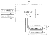
- the injection amount learning correction unit 90 includes a learning correction coefficient calculation unit 91 and an injection amount correction unit 92.
- the learning correction coefficient calculation unit 91 is based on the error ⁇ between the actual lambda value ⁇ Act detected by the NOx / lambda sensor 45 during the lean operation of the engine 10 and the estimated lambda value ⁇ Est, and the learning correction coefficient F for the fuel injection amount. Calculate Corr .
- the actual lambda value ⁇ Act in the exhaust gas that passes through the oxidation catalyst 31 and is detected by the downstream NOx / lambda sensor 45 It is considered that the estimated lambda value ⁇ Est in the exhaust discharged from the engine 10 coincides.
- step S300 based on the engine speed Ne and the accelerator opening Q, it is determined whether or not the engine 10 is in a lean operation state. If it is in the lean operation state, the process proceeds to step S310 to start the calculation of the learning correction coefficient.
- the estimated lambda value ⁇ Est is estimated and calculated from the operating state of the engine 10 according to the engine speed Ne and the accelerator opening Q. Further, the correction sensitivity coefficient K 2 is read the actual lambda value lambda Act detected by the NOx / lambda sensor 45 from the correction sensitivity coefficient map 91A shown in FIG. 9 as an input signal.
- step S320 it is determined whether or not the absolute value
- step S330 it is determined whether the learning prohibition flag FPro is off.
- Whether or not the engine 10 is in a transient operation state is determined based on, for example, the time change amount of the actual lambda value ⁇ Act detected by the NOx / lambda sensor 45 when the time change amount is larger than a predetermined threshold value. What is necessary is just to determine with a transient operation state.
- step S340 the learning value map 91B (see FIG. 9) referred to based on the engine speed Ne and the accelerator opening Q is updated to the learning value F CorrAdpt calculated in step S310. More specifically, on the learning value map 91B, a plurality of learning areas divided according to the engine speed Ne and the accelerator opening Q are set. These learning regions are preferably set to have a narrower range as the region is used more frequently and to be wider as a region is used less frequently. As a result, learning accuracy is improved in regions where the usage frequency is high, and unlearning can be effectively prevented in regions where the usage frequency is low.
- the learning correction coefficient F Corr is input to the injection amount correction unit 92 shown in FIG.
- the injection amount correction unit 92 multiplies each basic injection amount of pilot injection Q Pilot , pre-injection Q Pre , main injection Q Main , after-injection Q After , and post-injection Q Post by a learning correction coefficient F Corr. The injection amount is corrected.
- MAF correction coefficient calculating unit 95 calculates the MAF correction coefficient Maf _Corr used to set the MAF target value MAF NPL_Trgt and the target injection amount Q NPR_Trgt during NOx purge control.
- the fuel injection amount of each injector 11 is corrected based on the error ⁇ between the actual lambda value ⁇ Act and the estimated lambda value ⁇ Est detected by the NOx / lambda sensor 45.
- the factor of error ⁇ is not necessarily only the effect of the difference between the commanded injection amount and the actual injection amount for each injector 11. That is, there is a possibility that the error of not only each injector 11 but also the MAF sensor 40 affects the lambda error ⁇ .
- FIG. 11 is a block diagram showing the setting process of the MAF correction coefficient Maf_corr by the MAF correction coefficient calculation unit 95.
- the correction coefficient setting map 96 is a map that is referred to based on the engine speed Ne and the accelerator opening Q.
- the MAF indicating the sensor characteristics of the MAF sensor 40 corresponding to the engine speed Ne and the accelerator opening Q.
- the correction coefficient Maf_corr is set in advance based on experiments or the like.
- the MAF correction coefficient calculation unit 95 reads the MAF correction coefficient Maf_corr from the correction coefficient setting map 96 using the engine speed Ne and the accelerator opening Q as input signals, and uses the MAF correction coefficient Maf_corr as the MAF target value calculation unit 72 and It transmits to the injection quantity target value calculating part 77.
- the sensor characteristics of the MAF sensor 40 can be effectively reflected in the settings of the MAF target value MAF NPL_Trgt and the target injection amount Q NPR_Trgt during the NOx purge control.
- the exhaust purification system and the control method thereof according to the present invention have the effect that the injection system control can be performed in a state where the intake air amount is sufficiently lowered, and the fuel consumption can be improved by reducing the injection system control time It is useful in that respect.
Landscapes
- Engineering & Computer Science (AREA)
- Chemical & Material Sciences (AREA)
- Combustion & Propulsion (AREA)
- Mechanical Engineering (AREA)
- General Engineering & Computer Science (AREA)
- Chemical Kinetics & Catalysis (AREA)
- Health & Medical Sciences (AREA)
- Toxicology (AREA)
- Biomedical Technology (AREA)
- Environmental & Geological Engineering (AREA)
- Analytical Chemistry (AREA)
- General Chemical & Material Sciences (AREA)
- Oil, Petroleum & Natural Gas (AREA)
- Exhaust Gas After Treatment (AREA)
- Combined Controls Of Internal Combustion Engines (AREA)
- Exhaust Gas Treatment By Means Of Catalyst (AREA)
- Electrical Control Of Air Or Fuel Supplied To Internal-Combustion Engine (AREA)
Abstract
エンジン10の排気通路に設けられて排気空燃比がリーン状態では排気中のNOxを吸蔵するNOx還元型触媒32と、エンジン10の吸入空気量を検出するMAFセンサ40と、吸入空気量を減少させる空気系制御と燃料噴射量を増加させる噴射系制御を併用してリーン状態からリッチ状態に切り替えることで、吸蔵されたNOxを還元浄化してNOx還元型触媒32から放出させるECU50を備える排気浄化システムであって、ECU50は、第1MAF目標値MAFL_Trgtと第2MAF目標値MAFNPL_Trgtとの差分値であるMAF目標値変化量△MAFTrgtと、第1MAF目標値MAFL_Trgtと実MAF値MAFActの差分値である実MAF変化量ΔMAFActの比率(実MAF変化率ΔMAFRatio)に基づき、噴射系制御の開始時期を判定する。
Description
本発明は、排気浄化システム及びその制御方法に関する。
従来、内燃機関から排出される排気中の窒素化合物(NOx)を還元浄化する触媒として、NOx吸蔵還元型触媒が知られている。このNOx吸蔵還元型触媒は、排気がリーン雰囲気のときに排気中に含まれるNOxを吸蔵すると共に、排気がリッチ雰囲気のときに排気中に含まれる炭化水素で吸蔵していたNOxを還元浄化により無害化して放出する。このため、触媒のNOx吸蔵量が所定量に達した場合は、NOx吸蔵能力を回復させるべく、ポスト噴射や排気管噴射によって排気をリッチ状態にする所謂NOxパージを定期的に行う必要がある(例えば、特許文献1参照)。
上述のNOxパージを、ポスト噴射や排気管噴射による噴射系制御のみで行うと、燃料消費量が過多となり燃費性能を悪化させる。このため、噴射系制御と吸気スロットルバルブやEGRバルブの開度調整により吸入空気量を減少させる空気系制御とを併用することが好ましい。
噴射系制御と空気系制御を併用する場合、空気系制御で吸入空気量を十分に下げてから噴射系制御を行うことが望ましい。排気の空気過剰率を十分に下げることができ、NOx吸蔵還元型触媒によってNOxを確実に還元浄化できるからである。しかしながら、空気系制御によって所望の吸入空気量に下げるための時間にはばらつきがある。このため、吸入空気量が十分に下がっていない状態で噴射系制御を行ってしまう可能性もあり、噴射系制御時間の増加に伴う燃料排出量の増加や燃費の悪化といった課題がある。
本開示の排気浄化システム及びその制御方法は、吸入空気量が十分に下がった状態で噴射系制御を行えるようにすることを目的とする。
本開示の排気浄化システムは、内燃機関の排気通路に設けられて排気空燃比がリーン状態では排気中のNOxを吸蔵するNOx還元型触媒と、前記内燃機関の吸入空気量を検出する吸入空気量センサと、吸入空気量を減少させる空気系制御と燃料噴射量を増加させる噴射系制御とを併用して前記排気空燃比を前記リーン状態からリッチ状態に切り替えることで、吸蔵されたNOxを還元浄化して前記NOx還元型触媒から放出させる制御部と、を備え、前記制御部は、前記リーン状態の第1目標吸入空気量と前記リッチ状態の第2目標吸入空気量との第1差分値と、前記第1目標吸入空気量と前記吸入空気量との第2差分値の比率に基づき、前記噴射系制御の開始時期を判定する。
また、本開示の排気浄化システムは、内燃機関の排気通路に配設され、前記内燃機関から排出される排気がリーン状態であるときに、前記排気に含まれるNOxを吸蔵するNOx還元型触媒と、前記内燃機関の吸入空気量を検出する吸入空気量センサと、吸入空気量を制御する空気系制御と、燃料噴射量を制御する噴射系制御とを併用することで前記排気の空燃比を制御する制御ユニットとを備える排気浄化システムであって、前記制御ユニットは、以下の処理を実行するように動作する:
前記空気系制御及び前記噴射系制御を実行することで前記排気の空燃比をリーン状態からリッチ状態に切り替えて、前記NOx還元型触媒に吸蔵されたNOxを前記NOx還元型触媒から放出させる触媒再生処理;
前記排気の空燃比がリーン状態であるときの目標吸入空気量である第1目標吸入空気量と前記内燃機関の吸入空気量との差分である第2差分値を算出する算出処理;及び
前記第1目標吸入空気量と、前記排気の空燃比がリッチ状態であるときの目標吸入空気量である第2目標吸入空気量との差分である第1差分値と、前記第2差分値との比率に基づいて、前記噴射系制御の開始時期を判定する判定処理。
前記空気系制御及び前記噴射系制御を実行することで前記排気の空燃比をリーン状態からリッチ状態に切り替えて、前記NOx還元型触媒に吸蔵されたNOxを前記NOx還元型触媒から放出させる触媒再生処理;
前記排気の空燃比がリーン状態であるときの目標吸入空気量である第1目標吸入空気量と前記内燃機関の吸入空気量との差分である第2差分値を算出する算出処理;及び
前記第1目標吸入空気量と、前記排気の空燃比がリッチ状態であるときの目標吸入空気量である第2目標吸入空気量との差分である第1差分値と、前記第2差分値との比率に基づいて、前記噴射系制御の開始時期を判定する判定処理。
本開示の排気浄化システムの制御方法は、内燃機関の排気通路に配設され、前記内燃機関から排出される排気がリーン状態であるときに、前記排気に含まれるNOxを吸蔵するNOx還元型触媒を備える排気浄化システムの制御方法であって、吸入空気量を制御する空気系制御と、燃料噴射量を制御する噴射系制御とを実行することで前記排気の空燃比をリーン状態からリッチ状態に切り替えて、前記NOx還元型触媒に吸蔵されたNOxを前記NOx還元型触媒から放出させる触媒再生処理;前記排気の空燃比がリーン状態であるときの目標吸入空気量である第1目標吸入空気量と前記内燃機関の吸入空気量との差分である第2差分値を算出する算出処理;及び前記第1目標吸入空気量と、前記排気の空燃比がリッチ状態であるときの目標吸入空気量である第2目標吸入空気量との差分である第1差分値と、前記第2差分値との比率に基づいて、前記噴射系制御の開始時期を判定する判定処理、を含む。
本開示の排気浄化システム及びその制御方法によれば、吸入空気量が十分に下がった状態で噴射系制御を行うことができる。
以下、添付図面に基づいて、本開示の一実施形態に係る排気浄化システムを説明する。
図1に示すように、ディーゼルエンジン(以下、単にエンジンという)10の各気筒には、図示しないコモンレールに蓄圧された高圧燃料を各気筒内に直接噴射するインジェクタ11がそれぞれ設けられている。これら各インジェクタ11の燃料噴射量や燃料噴射タイミングは、電子制御ユニット(以下、ECUという)50から入力される指示信号に応じてコントロールされる。
エンジン10の吸気マニホールド10Aには新気を導入する吸気通路12が接続され、排気マニホールド10Bには排気を外部に導出する排気通路13が接続されている。吸気通路12には、吸気上流側から順にエアクリーナ14、吸入空気量センサ(以下、MAFセンサという)40、可変容量型過給機20のコンプレッサ20A、インタークーラ15、吸気スロットルバルブ16等が設けられている。排気通路13には、排気上流側から順に可変容量型過給機20のタービン20B、排気後処理装置30等が設けられている。エンジン10には、エンジン回転数センサ41、アクセル開度センサ42、ブースト圧センサ46が取り付けられている。
なお、本実施形態の説明では、エンジンの吸入空気量(吸気流量(Suction Air Flow))を測定・検出する吸入空気量センサとして、質量流量(Mass Air Flow)を測定・検出するMAFセンサ40を用いるものとするが、エンジンの吸気流量を測定・検出することができれば、MAFセンサ40とは異なるタイプの流量(Air Flow)センサ、あるいは流量センサに代わる手段を用いてもよい。
EGR(Exhaust Gas Recirculation)装置21は、排気マニホールド10Bと吸気マニホールド10Aとを接続するEGR通路22と、EGRガスを冷却するEGRクーラ23と、EGR量を調整するEGRバルブ24とを備えている。
排気後処理装置30は、ケース30A内に排気上流側から順に酸化触媒31、NOx吸蔵還元型触媒32、パティキュレートフィルタ(以下、単にフィルタという)33を配置して構成されている。また、酸化触媒31よりも上流側の排気通路13には、ECU50から入力される指示信号に応じて、排気通路13内に未燃燃料(主に炭化水素(HC))を噴射する排気管噴射装置34が設けられている。
酸化触媒31は、例えば、ハニカム構造体等のセラミック製担体表面に酸化触媒成分を担持して形成されている。酸化触媒31は、排気管噴射装置34又はインジェクタ11のポスト噴射によって未燃燃料が供給されると、これを酸化して排気温度を上昇させる。
NOx吸蔵還元型触媒32は、例えば、ハニカム構造体等のセラミック製担体表面にアルカリ金属等を担持して形成されている。このNOx吸蔵還元型触媒32は、排気空燃比がリーン状態のときに排気中のNOxを吸蔵すると共に、排気空燃比がリッチ状態のときに排気中に含まれる還元剤(HC等)で吸蔵したNOxを還元浄化する。
フィルタ33は、例えば、多孔質性の隔壁で区画された多数のセルを排気の流れ方向に沿って配置し、これらセルの上流側と下流側とを交互に目封止して形成されている。フィルタ33は、排気中の粒子状物質(以下、PMともいう)を隔壁の細孔や表面に捕集すると共に、PM堆積推定量が所定量に達すると、これを燃焼除去するいわゆるフィルタ再生が実行される。フィルタ再生は、排気管噴射又はポスト噴射によって上流側の酸化触媒31に未燃燃料を供給し、フィルタ33に流入する排気温度をPM燃焼温度まで昇温することで行われる。
第1排気温度センサ43は、酸化触媒31よりも上流側に設けられており、酸化触媒31に流入する排気温度を検出する。第2排気温度センサ44は、NOx吸蔵還元型触媒32とフィルタ33との間に設けられており、フィルタ33に流入する排気温度を検出する。NOx/ラムダセンサ45は、フィルタ33よりも下流側に設けられており、NOx吸蔵還元型触媒32を通過した排気のNOx値及びラムダ値(以下、空気過剰率ともいう)を検出する。
ECU50は、本開示の制御部及び制御ユニットの一例であり、エンジン10等の各種制御を行う。ECU50は、公知のCPUやROM、RAM、入力ポート、出力ポート等を備えて構成されている。これら各種制御を行うため、ECU50にはセンサ類40~46のセンサ値が入力される。また、ECU50は、フィルタ再生制御部51と、NOxパージ制御部70と、MAF追従制御部80と、噴射量学習補正部90と、MAF補正係数演算部95とを一部の機能要素として有する。これら各機能要素は、一体のハードウェアであるECU50に含まれるものとして説明するが、これらのいずれか一部を別体のハードウェアに設けることもできる。
[フィルタ再生制御]
フィルタ再生制御部51は、車両の走行距離、あるいは図示しない差圧センサで検出されるフィルタ前後差圧からフィルタ33のPM堆積量を推定すると共に、このPM堆積推定量が所定の上限閾値を超えると、排気管噴射装置34に排気管噴射を実行させる指示信号が送信されるか、あるいは、各インジェクタ11にポスト噴射を実行させる指示信号が送信されて、排気温度をPM燃焼温度(例えば、約550℃)まで昇温させる。このフィルタ再生処理は、PM堆積推定量が燃焼除去を示す所定の下限閾値(判定閾値)まで低下すると終了される。なお、終了判定は、フィルタ再生開始からの上限経過時間や上限累積噴射量を基準にしてもよい。
フィルタ再生制御部51は、車両の走行距離、あるいは図示しない差圧センサで検出されるフィルタ前後差圧からフィルタ33のPM堆積量を推定すると共に、このPM堆積推定量が所定の上限閾値を超えると、排気管噴射装置34に排気管噴射を実行させる指示信号が送信されるか、あるいは、各インジェクタ11にポスト噴射を実行させる指示信号が送信されて、排気温度をPM燃焼温度(例えば、約550℃)まで昇温させる。このフィルタ再生処理は、PM堆積推定量が燃焼除去を示す所定の下限閾値(判定閾値)まで低下すると終了される。なお、終了判定は、フィルタ再生開始からの上限経過時間や上限累積噴射量を基準にしてもよい。
[NOxパージ制御]
NOxパージ制御部70は、排気をリッチ雰囲気にしてNOx吸蔵還元型触媒32に吸蔵されているNOxを還元浄化により無害化して放出することで、NOx吸蔵還元型触媒32のNOx吸蔵能力を回復させる制御(以下、この制御をNOxパージ制御という)を実行する。
NOxパージ制御部70は、排気をリッチ雰囲気にしてNOx吸蔵還元型触媒32に吸蔵されているNOxを還元浄化により無害化して放出することで、NOx吸蔵還元型触媒32のNOx吸蔵能力を回復させる制御(以下、この制御をNOxパージ制御という)を実行する。
図2に示すように、NOxパージ制御を開始するNOxパージフラグFNPは、エンジン10の運転状態から単位時間当たりのNOx排出量を推定し、これを累積計算した推定累積値ΣNOxが所定の閾値を超えるとオンにされる(図2の時刻t1参照)。あるいは、エンジン10の運転状態から推定される触媒上流側のNOx排出量と、NOx/ラムダセンサ45で検出される触媒下流側のNOx量とからNOx吸蔵還元型触媒32によるNOx浄化率を演算し、このNOx浄化率が所定の判定閾値よりも低くなった場合に、NOxパージフラグFNPはオンにされる。
本実施形態において、NOxパージ制御によるリッチ化は、空気系制御によって空気過剰率を定常運転時(例えば、約1.5)から理論空燃比相当値(約1.0)よりもリーン側の第1目標空気過剰率(例えば、約1.3)まで低下させるNOxパージリーン制御と、噴射系制御によって空気過剰率を第1目標空気過剰率からリッチ側の第2目標空気過剰率(例えば、約0.9)まで低下させるNOxパージリッチ制御とを併用することで実現される。以下、NOxパージリーン制御及び、NOxパージリッチ制御の詳細について説明する。
[NOxパージリーン制御のMAF目標値設定]
図3は、NOxパージリーン制御時のMAF目標値MAFNPL_Trgtの設定処理を示すブロック図である。第1目標空気過剰率設定マップ71は、エンジン回転数Ne及びアクセル開度Qに基づいて参照されるマップであって、これらエンジン回転数Neとアクセル開度Qとに対応したNOxパージリーン制御時の空気過剰率目標値λNPL_Trgt(第1目標空気過剰率)が予め実験等に基づいて設定されている。
図3は、NOxパージリーン制御時のMAF目標値MAFNPL_Trgtの設定処理を示すブロック図である。第1目標空気過剰率設定マップ71は、エンジン回転数Ne及びアクセル開度Qに基づいて参照されるマップであって、これらエンジン回転数Neとアクセル開度Qとに対応したNOxパージリーン制御時の空気過剰率目標値λNPL_Trgt(第1目標空気過剰率)が予め実験等に基づいて設定されている。
まず、第1目標空気過剰率設定マップ71から、エンジン回転数Ne及びアクセル開度Qを入力信号としてNOxパージリーン制御時の空気過剰率目標値λNPL_Trgtが読み取られて、MAF目標値演算部72に入力される。さらに、MAF目標値演算部72では、以下の数式(1)に基づいてNOxパージリーン制御時のMAF目標値MAFNPL_Trgtが演算される。
MAFNPL_Trgt=λNPL_Trgt×Qfnl_corrd×RoFuel×AFRsto/Maf_corr・・・(1)
数式(1)において、Qfnl_corrdは後述する学習補正された燃料噴射量(ポスト噴射を除く)、RoFuelは燃料比重、AFRstoは理論空燃比、Maf_corrは後述するMAF補正係数をそれぞれ示している。
数式(1)において、Qfnl_corrdは後述する学習補正された燃料噴射量(ポスト噴射を除く)、RoFuelは燃料比重、AFRstoは理論空燃比、Maf_corrは後述するMAF補正係数をそれぞれ示している。
MAF目標値演算部72によって演算されたMAF目標値MAFNPL_Trgtは、NOxパージフラグFNPがオン(図2の時刻t1参照)になるとランプ処理部73に入力される。ランプ処理部73は、+ランプ係数マップ73A及び-ランプ係数マップ73Bからエンジン回転数Ne及びアクセル開度Qを入力信号としてランプ係数を読み取ると共に、このランプ係数を付加したMAF目標ランプ値MAFNPL_Trgt_Rampをバルブ制御部74に入力する。
バルブ制御部74は、MAFセンサ40から入力される実MAF値MAFActがMAF目標ランプ値MAFNPL_Trgt_Rampとなるように、吸気スロットルバルブ16を閉側に絞ると共に、EGRバルブ24を開側に開くフィードバック制御を実行する。
このように、本実施形態では、第1目標空気過剰率設定マップ71から読み取られる空気過剰率目標値λNPL_Trgtと、各インジェクタ11の燃料噴射量とに基づいてMAF目標値MAFNPL_Trgtを設定し、このMAF目標値MAFNPL_Trgtに基づいて空気系動作をフィードバック制御するようになっている。これにより、NOx吸蔵還元型触媒32の上流側にラムダセンサを設けることなく、或いは、NOx吸蔵還元型触媒32の上流側にラムダセンサを設けた場合も当該ラムダセンサのセンサ値を用いることなく、排気をNOxパージリーン制御に必要な所望の空気過剰率まで効果的に低下させることが可能になる。
また、各インジェクタ11の燃料噴射量として学習補正後の燃料噴射量Qfnl_corrdを用いることで、MAF目標値MAFNPL_Trgtをフィードフォワード制御で設定することが可能となり、各インジェクタ11の経年劣化や特性変化等の影響を効果的に排除することができる。
また、MAF目標値MAFNPL_Trgtにエンジン10の運転状態に応じて設定されるランプ係数を付加することで、吸入空気量の急激な変化によるエンジン10の失火やトルク変動によるドライバビリティーの悪化等を効果的に防止することができる。
[NOxパージリッチ制御の燃料噴射量設定]
図4は、NOxパージリッチ制御における排気管噴射又はポスト噴射の目標噴射量QNPR_Trgt(単位時間当たりの噴射量)の設定処理を示すブロック図である。
図4は、NOxパージリッチ制御における排気管噴射又はポスト噴射の目標噴射量QNPR_Trgt(単位時間当たりの噴射量)の設定処理を示すブロック図である。
噴射系制御開始判定部75は、NOxパージ制御部70による噴射系制御の開始タイミングを判定する。噴射系制御開始判定部75には、MAFセンサ40の検出信号が入力されると共に、リーン状態からリッチ状態への切り替え前(リーン状態)のMAF目標値である第1MAF目標値MAFL_Trgtと、切り替え後(リッチ状態)のMAF目標値である第2MAF目標値MAFNPL_Trgtと、噴射系制御の開始タイミングの到来を判定するための判定用閾値とが参照される。本実施形態における判定用閾値はECU50の記憶部(不図示)に記憶されており、最大値から最小値の範囲内で変更可能である。
図5の時刻t1に示すように、NOxパージフラグFNPがオン(FNP=1)にされると、噴射系制御開始判定部75は、第2MAF目標値MAFNPL_Trgtから第1MAF目標値MAFL_Trgtを減算することで、切り替え前後のMAF目標値変化量ΔMAFTrgt(=MAFNPL_Trgt-MAFL_Trgt)を演算する。このMAF目標値変化量ΔMAFTrgtは、本開示の第1差分値の一例である。
次に、噴射系制御開始判定部75は、MAFセンサ40で検出される現在の実MAF値MAFActから第1MAF目標値MAFL_Trgtを減算することで、MAF追従制御の開始から現在までの実MAF変化量ΔMAFAct(=MAFAct-MAFL_Trgt)を演算する。この実MAF変化量ΔMAFActは、本開示の第2差分値の一例である。
そして、噴射系制御開始判定部75は、実MAF変化量ΔMAFActを切り替え前後のMAF目標値変化量ΔMAFTrgtで除算することで、実MAF変化率ΔMAFRatio(=ΔMAFAct/ΔMAFTrgt)を演算する。この実MAF変化率ΔMAFRatioは、本開示の第1差分値と第2差分値の比率の一例である。
さらに、噴射系制御開始判定部75は、実MAF変化率ΔMAFRatioをリアルタイムで演算すると共に判定用閾値と比較し、実MAF変化率ΔMAFRatioが判定用閾値以上となった場合に、MAFが十分に下がったとして、噴射量目標値演算部77に対して開始信号を出力し、噴射系制御の開始を指示する。図5の例では、時刻t2で実MAF変化率ΔMAFRatioが判定用閾値に到達したことから、噴射量目標値演算部77に対して噴射系制御の開始が指示されている。これにより、時刻t2以降にポスト噴射や排気管噴射が行われる。
第2目標空気過剰率設定マップ76は、エンジン回転数Ne及びアクセル開度Qに基づいて参照されるマップであって、これらエンジン回転数Neとアクセル開度Qとに対応したNOxパージリッチ制御時の空気過剰率目標値λNPR_Trgt(第2目標空気過剰率)が予め実験等に基づいて設定されている。
まず、第2目標空気過剰率設定マップ76から、エンジン回転数Ne及びアクセル開度Qを入力信号としてNOxパージリッチ制御時の空気過剰率目標値λNPR_Trgtが読み取られて噴射量目標値演算部77に入力される。
噴射量目標値演算部77では、以下の数式(2)に基づいてNOxパージリッチ制御時の目標噴射量QNPR_Trgtが演算される。この演算は、噴射系制御開始判定部75からの開始信号が入力されたことを条件に行われる。
QNPR_Trgt=MAFNPL_Trgt×Maf_corr/(λNPR_Trgt×RoFuel×AFRsto)-Qfnl_corrd・・・(2)
数式(2)において、MAFNPL_TrgtはNOxパージリーンMAF目標値であって、前述のMAF目標値演算部72から入力される。また、Qfnl_corrdは後述する学習補正されたMAF追従制御適用前の燃料噴射量(ポスト噴射を除く)、RoFuelは燃料比重、AFRstoは理論空燃比、Maf_corrは後述するMAF補正係数をそれぞれ示している。
数式(2)において、MAFNPL_TrgtはNOxパージリーンMAF目標値であって、前述のMAF目標値演算部72から入力される。また、Qfnl_corrdは後述する学習補正されたMAF追従制御適用前の燃料噴射量(ポスト噴射を除く)、RoFuelは燃料比重、AFRstoは理論空燃比、Maf_corrは後述するMAF補正係数をそれぞれ示している。
噴射量目標値演算部77によって演算される目標噴射量QNPR_Trgtは、各インジェクタ11又は排気管噴射装置34に噴射指示信号として送信される(図2及び図5の時刻t2)。この噴射指示信号の送信は、後述するNOxパージ制御の終了判定によってNOxパージフラグFNPがオフ(図2の時刻t4)にされるまで継続される。これにより、各インジェクタ11によるポスト噴射や排気管噴射装置34による排気管噴射が行われる。
このように、本実施形態では、空気系制御(NOxパージリーン制御)によるMAF値の目標到達度を、噴射系制御開始判定部75で演算された実MAF変化率ΔMAFRatioに基づいて判定している。そして、噴射系制御開始判定部75は、実MAF変化率ΔMAFRatioが所定の判定用閾値に到達した場合に、噴射系制御(ポスト噴射,排気管噴射)を開始させている。その結果、MAFが十分に下がった状態で未燃燃料が供給される。言い換えれば、リッチ制御によるNOx還元の効果が見込める状況下で未燃燃料が供給される。その結果、噴射系制御時間が短縮されて燃費の向上が図れる。
また、ECU50は、判定用閾値に関し、最大値から最小値までの範囲内で数値を変更可能に記憶しているので、システムに適した判定基準を容易に設定できる。
また、本実施形態では、第2目標空気過剰率設定マップ76から読み取られる空気過剰率目標値λNPR_Trgtと、各インジェクタ11の燃料噴射量とに基づいて目標噴射量QNPR_Trgtを設定するようになっている。これにより、NOx吸蔵還元型触媒32の上流側にラムダセンサを設けることなく、或いは、NOx吸蔵還元型触媒32の上流側にラムダセンサを設けた場合も当該ラムダセンサのセンサ値を用いることなく、排気をNOxパージリッチ制御に必要な所望の空気過剰率まで効果的に低下させることが可能になる。
また、各インジェクタ11の燃料噴射量として学習補正後の燃料噴射量Qfnl_corrdを用いることで、目標噴射量QNPR_Trgtをフィードフォワード制御で設定することが可能となり、各インジェクタ11の経年劣化や特性変化等の影響を効果的に排除することができる。
[NOxパージ制御の空気系制御禁止]
ECU50は、エンジン10の運転状態が低負荷側の領域では、MAFセンサ40のセンサ値に基づいて吸気スロットルバルブ16やEGRバルブ24の開度をフィードバック制御している。一方、エンジン10の運転状態が高負荷側の領域では、ECU50はブースト圧センサ46のセンサ値に基づいて可変容量型過給機20による過給圧をフィードバック制御している(以下、この領域をブースト圧FB制御領域という)。
ECU50は、エンジン10の運転状態が低負荷側の領域では、MAFセンサ40のセンサ値に基づいて吸気スロットルバルブ16やEGRバルブ24の開度をフィードバック制御している。一方、エンジン10の運転状態が高負荷側の領域では、ECU50はブースト圧センサ46のセンサ値に基づいて可変容量型過給機20による過給圧をフィードバック制御している(以下、この領域をブースト圧FB制御領域という)。
このようなブースト圧FB制御領域では、吸気スロットルバルブ16やEGRバルブ24の制御が可変容量型過給機20の制御と干渉してしまう現象が生じる。このため、上述の数式(1)で設定されるMAF目標値MAFNPL_Trgtに基づいて空気系をフィードバック制御するNOxパージリーン制御を実行しても、吸入空気量をMAF目標値MAFNPL_Trgtに維持できない課題がある。その結果、ポスト噴射や排気管噴射を実行するNOxパージリッチ制御を開始しても、空気過剰率をNOxパージに必要な第2目標空気過剰率(空気過剰率目標値λNPR_Trgt)まで低下させられない可能性がある。
このような現象を回避すべく、本実施形態のNOxパージ制御部70は、ブースト圧FB制御領域では、吸気スロットルバルブ16やEGRバルブ24の開度を調整するNOxパージリーン制御を禁止し、排気管噴射又はポスト噴射のみで空気過剰率を第2目標空気過剰率(空気過剰率目標値λNPR_Trgt)まで低下させる。これにより、ブースト圧FB制御領域においても、NOxパージを確実に行うことが可能になる。なお、この場合、上述の数式(2)のMAF目標値MAFNPL_Trgtには、エンジン10の運転状態に基づいて設定されるMAF目標値を適用すればよい。
[NOxパージ制御の終了判定]
NOxパージ制御は、(1)NOxパージフラグFNPのオンから排気管噴射又はポスト噴射の噴射量を累積し、この累積噴射量が所定の上限閾値量に達した場合、(2)NOxパージ制御の開始から計時した経過時間が所定の上限閾値時間に達した場合、(3)エンジン10の運転状態やNOx/ラムダセンサ45のセンサ値等を入力信号として含む所定のモデル式に基づいて演算されるNOx吸蔵還元型触媒32のNOx吸蔵量がNOx除去成功を示す所定の閾値まで低下した場合の何れかの条件が成立すると、NOxパージフラグFNPをオフにして終了される(図2の時刻t4参照)。
NOxパージ制御は、(1)NOxパージフラグFNPのオンから排気管噴射又はポスト噴射の噴射量を累積し、この累積噴射量が所定の上限閾値量に達した場合、(2)NOxパージ制御の開始から計時した経過時間が所定の上限閾値時間に達した場合、(3)エンジン10の運転状態やNOx/ラムダセンサ45のセンサ値等を入力信号として含む所定のモデル式に基づいて演算されるNOx吸蔵還元型触媒32のNOx吸蔵量がNOx除去成功を示す所定の閾値まで低下した場合の何れかの条件が成立すると、NOxパージフラグFNPをオフにして終了される(図2の時刻t4参照)。
このように、本実施形態では、NOxパージ制御の終了条件に累積噴射量及び、経過時間の上限を設けたことで、NOxパージが排気温度の低下等によって成功しなかった場合に燃料消費量が過剰になることを確実に防止することができる。
[MAF追従制御]
MAF追従制御部80は、(1)通常運転のリーン状態からNOxパージ制御によるリッチ状態への切り替え期間及び、(2)NOxパージ制御によるリッチ状態から通常運転のリーン状態への切り替え期間に、各インジェクタ11の燃料噴射タイミング及び燃料噴射量をMAF変化に応じて補正する制御(以下、この制御をMAF追従制御という)を実行する。
MAF追従制御部80は、(1)通常運転のリーン状態からNOxパージ制御によるリッチ状態への切り替え期間及び、(2)NOxパージ制御によるリッチ状態から通常運転のリーン状態への切り替え期間に、各インジェクタ11の燃料噴射タイミング及び燃料噴射量をMAF変化に応じて補正する制御(以下、この制御をMAF追従制御という)を実行する。
NOxパージリーン制御の空気系動作によってエンジン10の燃焼室内に大量のEGRガスが導入されると、通常運転のリーン状態と同じ燃料噴射タイミングでは着火遅れが生じる。そのため、リーン状態からリッチ状態に切り替える場合は、噴射タイミングを所定量ほど進角させる必要がある。また、リッチ状態から通常のリーン状態に切り替える際は、噴射タイミングを遅角により通常の噴射タイミングに戻す必要がある。しかしながら、噴射タイミングの進角や遅角は、空気系動作よりも迅速に行われる。このため、空気系動作によって空気過剰率が目標空気過剰率に達する前に噴射タイミングの進角や遅角が完了してしまい、NOx発生量や燃焼騒音やトルク等の急増加によるドライバビリティーの悪化を招く課題がある。
このような現象を回避すべく、MAF追従制御部80は、図6,7のフローチャートに示すように、MAF変化に応じて噴射タイミングの進角や遅角、噴射量を増減補正するMAF追従制御を実行する。
まず、図6に基づいて、リーン状態からリッチ状態への切り替え期間のMAF追従制御を説明する。
ステップS100で、NOxパージフラグFNPがオン(FNP=1)にされると、ステップS110では、MAF追従制御の経過時間を計測すべくタイマによる計時が開始される。
ステップS120では、切り替え後(リッチ状態)のMAF目標値MAFNPL_Trgtから切り替え前(リーン状態)のMAF目標値MAFL_Trgtを減算することで、切り替え前後のMAF目標値変化量ΔMAFTrgt(=MAFNPL_Trgt-MAFL_Trgt)が演算される。
ステップS130では、現在の実MAF変化率ΔMAFRatioが演算される。より詳しくは、MAFセンサ40で検出される現在の実MAF値MAFActから切り替え前のMAF目標値MAFL_Trgtを減算することで、MAF追従制御の開始から現在までの実MAF変化量ΔMAFAct(=MAFAct-MAFL_Trgt)が演算される。そして、この実MAF変化量ΔMAFActを切り替え前後のMAF目標値変化量ΔMAFTrgtで除算することで、実MAF変化率ΔMAFRatio(=ΔMAFAct/ΔMAFTrgt)が演算される。
ステップS140では、現在の実MAF変化率ΔMAFRatioに応じて、各インジェクタ11の噴射タイミングを進角又は遅角させる係数(以下、噴射タイミング追従係数Comp1と称する)及び、各インジェクタ11の噴射量を増加又は減少させる係数(以下、噴射量追従係数Comp2と称する)が設定される。より詳しくは、ECU50の図示しない記憶部には、予め実験等により作成した実MAF変化率MAFRatioと噴射タイミング追従係数Comp1との関係を規定した噴射タイミング追従係数設定マップM1及び、実MAF変化率MAFRatioと噴射量追従係数Comp2との関係を規定した噴射量追従係数設定マップM2が記憶されている。噴射タイミング追従係数Comp1及び、噴射量追従係数Comp2は、これらのマップM1,M2から、ステップS130で演算した実MAF変化率ΔMAFRatioに対応する値をそれぞれ読み取ることで設定される。
ステップS150では、目標進角量に噴射タイミング追従係数Comp1を乗じた分だけ各インジェクタ11の噴射タイミングが進角されると共に、目標噴射増加量に噴射量追従係数Comp2を乗じた分だけ各インジェクタ11も燃料噴射量が増加される。
その後、ステップS160では、MAFセンサ40で検出される現在の実MAF値MAFActが切り替え後(リッチ状態)のMAF目標値MAFNPL_Trgtに達したか否かが判定される。実MAF値MAFActがMAF目標値MAFNPL_Trgtに達していない場合(No)は、ステップS170を経由してステップS130に戻される。すなわち、実MAF値MAFActがMAF目標値MAFNPL_Trgtになるまで、ステップS130~S150の処理を繰り返すことで、時々刻々と変化する実MAF変化率MAFRatioに応じた噴射タイミングの進角及び、噴射量の増加が継続される。ステップS170の処理についての詳細は後述する。一方、ステップS160の判定で、実MAF値MAFActがMAF目標値MAFNPL_Trgtに達すると(Yes)、本制御は終了する。
ステップS170では、MAF追従制御の開始からタイマによって計時された累積時間TSumが、所定の上限時間TMaxを超えたか否かが判定される。
図8(A)に示すように、リーン状態からリッチ状態に移行する際に、バルブ制御遅れ等の影響で実MAF値MAFActが移行期間中のMAF目標値MAFL-R_Trgtに追いつけず、実MAF値MAFActがMAF目標値MAFL-R_Trgtよりも高い状態に維持される場合がある(時刻t1~t2参照)。このような状態でMAF追従制御を継続すると、実際の燃料噴射量が目標噴射量まで増加されず、エンジン10の燃焼が不安定になり、トルク変動やドライバビリティーの悪化等を招く可能性がある。
本実施形態では、このような現象を回避すべく、ステップS170にて、累積時間TSumが上限時間TMaxを超えたと判定された場合(Yes)、すなわち、実MAF値MAFActが所定時間継続して所定値以上変化しなかった場合は、ステップS180に進み、噴射タイミング追従係数Comp1及び、噴射量追従係数Comp2を強制的に「1」に設定する。これにより、MAF追従制御が強制的に終了されて、トルク変動やドライバビリティーの悪化を効果的に防止することができる。
次に、図7に基づいて、リッチ状態からリーン状態への切り替え時のMAF追従制御を説明する。
ステップS200で、NOxパージフラグFNPがオフ(FNP=0)にされると、ステップS210では、MAF追従制御の経過時間を計測すべくタイマによる計時が開始される。
ステップS220では、切り替え後(リーン状態)のMAF目標値MAFL_Trgtから切り替え前(リッチ状態)のMAF目標値MAFNPL_Trgtを減算することで、切り替え前後のMAF目標値変化量ΔMAFTrgt(=MAFL_Trgt-MAFNPL_Trgt)が算出される。
ステップS230では、現在の実MAF変化率ΔMAFRatioが演算される。より詳しくは、MAFセンサ40で検出される現在の実MAF値MAFActから切り替え前のMAF目標値MAFNPL_Trgtを減算することで、MAF追従制御の開始から現在までの実MAF変化量ΔMAFAct(=MAFAct-MAFNPL_Trgt)が演算される。そして、この実MAF変化量ΔMAFActを切り替え前後のMAF目標値変化量ΔMAFTrgtで除算することで、実MAF変化率ΔMAFRatio(=ΔMAFAct/ΔMAFTrgt)が演算される。
ステップS240では、噴射タイミング追従係数設定マップM1から実MAF変化率ΔMAFRatioに対応する値が噴射タイミング追従係数Comp1として読み取られると共に、噴射量追従係数設定マップM2から実MAF変化率ΔMAFRatioに対応する値が噴射量追従係数Comp2として読み取られる。
ステップS250では、目標遅角量に噴射タイミング追従係数Comp1を乗じた分だけ各インジェクタ11の噴射タイミングが遅角されると共に、目標噴射減少量に噴射量追従係数Comp2を乗じた分だけ各インジェクタ11も燃料噴射量が減少される。
その後、ステップS260では、MAFセンサ40で検出される現在の実MAF値MAFActが切り替え後(リーン状態)のMAF目標値MAFL_Trgtに達したか否かが判定される。実MAF値MAFActがMAF目標値MAFL_Trgtに達していない場合(No)は、ステップS270を経由してステップS230に戻される。すなわち、実MAF値MAFActがMAF目標値MAFL_Trgtになるまで、ステップS230~S250の処理を繰り返すことで、時々刻々と変化する実MAF変化率MAFRatioに応じた噴射タイミングの遅角及び、噴射量の減少が継続される。ステップS270の処理についての詳細は後述する。一方、ステップS260の判定で、実MAF値MAFActがMAF目標値MAFL_Trgtに達すると(Yes)、本制御は終了する。
ステップS270では、MAF追従制御の開始からタイマによって計時された累積時間TSumが、所定の上限時間TMaxを超えたか否かが判定される。
図8(B)に示すように、リーン状態からリッチ状態に移行する際に、バルブ制御遅れ等の影響で実MAF値MAFActが移行期間中のMAF目標値MAFL-R_Trgtに追いつけず、実MAF値MAFActがMAF目標値MAFL-R_Trgtよりも低い状態を維持する場合がある(時刻t1~t2参照)。このような状態でMAF追従制御を継続すると、実際の燃料噴射量が目標噴射量よりも多くなり、トルク変動やドライバビリティーの悪化等を招く可能性がある。
本実施形態では、このような現象を回避すべく、ステップS270にて、累積時間TSumが上限時間TMaxを超えたと判定された場合(Yes)、すなわち、実MAF値MAFActが所定時間継続して所定値以上変化しなかった場合は、ステップS280に進み、噴射タイミング追従係数Comp1及び、噴射量追従係数Comp2を強制的に「1」に設定する。これにより、MAF追従制御が強制的に終了されて、トルク変動やドライバビリティーの悪化を効果的に防止することができる。
[MAF追従制御の禁止]
上述したように、ブースト圧FB制御領域では、MAFセンサ40のセンサ値に基づいて空気系をフィードバック制御するNOxパージリーン制御を禁止している。MAF追従制御も吸入空気量の変化率に応じて噴射タイミングの進角や噴射量の増加を制御しているため、ブースト圧FB制御領域では正確な制御を行えない可能性がある。
上述したように、ブースト圧FB制御領域では、MAFセンサ40のセンサ値に基づいて空気系をフィードバック制御するNOxパージリーン制御を禁止している。MAF追従制御も吸入空気量の変化率に応じて噴射タイミングの進角や噴射量の増加を制御しているため、ブースト圧FB制御領域では正確な制御を行えない可能性がある。
そこで、本実施形態は、ブースト圧FB制御領域ではMAF追従係数Comp1,2を「1」に設定することで、MAF追従制御の実行を禁止するようになっている。これにより、MAF追従制御が不正確になることで引き起こされるエンジン10のトルク変動やドライバビリティーの悪化が効果的に防止される。
[噴射量学習補正]
図9に示すように、噴射量学習補正部90は、学習補正係数演算部91と、噴射量補正部92とを有する。
図9に示すように、噴射量学習補正部90は、学習補正係数演算部91と、噴射量補正部92とを有する。
学習補正係数演算部91は、エンジン10のリーン運転時にNOx/ラムダセンサ45で検出される実ラムダ値λActと、推定ラムダ値λEstとの誤差Δλに基づいて燃料噴射量の学習補正係数FCorrを演算する。排気がリーン状態のときは、酸化触媒31でHCの酸化反応が生じないため、酸化触媒31を通過して下流側のNOx/ラムダセンサ45で検出される排気中の実ラムダ値λActと、エンジン10から排出された排気中の推定ラムダ値λEstとは一致すると考えられる。このため、これら実ラムダ値λActと推定ラムダ値λEstとに誤差Δλが生じた場合は、各インジェクタ11に対する指示噴射量と実噴射量との差によるものと仮定することができる。以下、この誤差Δλを用いた学習補正係数演算部91による学習補正係数の演算処理を図10のフローに基づいて説明する。
ステップS300では、エンジン回転数Ne及びアクセル開度Qに基づいて、エンジン10がリーン運転状態にあるか否かが判定される。リーン運転状態にあれば、学習補正係数の演算を開始すべく、ステップS310に進む。
ステップS310では、推定ラムダ値λEstからNOx/ラムダセンサ45で検出される実ラムダ値λActを減算した誤差Δλに、学習値ゲインK1及び補正感度係数K2を乗じることで、学習値FCorrAdptが演算される(FCorrAdpt=(λEst-λAct)×K1×K2)。推定ラムダ値λEstは、エンジン回転数Neやアクセル開度Qに応じたエンジン10の運転状態から推定演算される。また、補正感度係数K2は、図9に示す補正感度係数マップ91AからNOx/ラムダセンサ45で検出される実ラムダ値λActを入力信号として読み取られる。
ステップS320では、学習値FCorrAdptの絶対値|FCorrAdpt|が所定の補正限界値Aの範囲内にあるか否かが判定される。絶対値|FCorrAdpt|が補正限界値Aを超えている場合、本制御はリターンされて今回の学習を中止する。
ステップS330では、学習禁止フラグFProがオフか否かが判定される。学習禁止フラグFProとしては、例えば、エンジン10の過渡運転時、NOxパージ制御時(FNP=1)等が該当する。これらの条件が成立する状態では、実ラムダ値λActの変化によって誤差Δλが大きくなり、正確な学習を行えないためである。エンジン10が過渡運転状態にあるか否かは、例えば、NOx/ラムダセンサ45で検出される実ラムダ値λActの時間変化量に基づいて、当該時間変化量が所定の閾値よりも大きい場合に過渡運転状態と判定すればよい。
ステップS340では、エンジン回転数Ne及びアクセル開度Qに基づいて参照される学習値マップ91B(図9参照)が、ステップS310で演算された学習値FCorrAdptに更新される。より詳しくは、この学習値マップ91B上には、エンジン回転数Ne及びアクセル開度Qに応じて区画された複数の学習領域が設定されている。これら学習領域は、好ましくは、使用頻度が多い領域ほどその範囲が狭く設定され、使用頻度が少ない領域ほどその範囲が広く設定されている。これにより、使用頻度が多い領域では学習精度が向上され、使用頻度が少ない領域では未学習を効果的に防止することが可能になる。
ステップS350では、エンジン回転数Ne及びアクセル開度Qを入力信号として学習値マップ91Bから読み取った学習値に「1」を加算することで、学習補正係数FCorrが演算される(FCorr=1+FCorrAdpt)。この学習補正係数FCorrは、図9に示す噴射量補正部92に入力される。
噴射量補正部92は、パイロット噴射QPilot、プレ噴射QPre、メイン噴射QMain、アフタ噴射QAfter、ポスト噴射QPostの各基本噴射量に学習補正係数FCorrを乗算することで、これら燃料噴射量の補正を実行する。
このように、推定ラムダ値λEstと実ラムダ値λActとの誤差Δλに応じた学習値で各インジェクタ11に燃料噴射量を補正することで、各インジェクタ11の経年劣化や特性変化、個体差等のバラツキを効果的に排除することが可能になる。
[MAF補正係数]
MAF補正係数演算部95は、NOxパージ制御時のMAF目標値MAFNPL_Trgtや目標噴射量QNPR_Trgtの設定に用いられるMAF補正係数Maf_corrを演算する。
MAF補正係数演算部95は、NOxパージ制御時のMAF目標値MAFNPL_Trgtや目標噴射量QNPR_Trgtの設定に用いられるMAF補正係数Maf_corrを演算する。
本実施形態において、各インジェクタ11の燃料噴射量は、NOx/ラムダセンサ45で検出される実ラムダ値λActと推定ラムダ値λEstとの誤差Δλに基づいて補正される。しかしながら、ラムダは空気と燃料の比であるため、誤差Δλの要因が必ずしも各インジェクタ11に対する指示噴射量と実噴射量との差の影響のみとは限らない。すなわち、ラムダの誤差Δλには、各インジェクタ11のみならずMAFセンサ40の誤差も影響している可能性がある。
図11は、MAF補正係数演算部95によるMAF補正係数Maf_corrの設定処理を示すブロック図である。補正係数設定マップ96は、エンジン回転数Ne及びアクセル開度Qに基づいて参照されるマップであって、これらエンジン回転数Neとアクセル開度Qとに対応したMAFセンサ40のセンサ特性を示すMAF補正係数Maf_corrが予め実験等に基づいて設定されている。
MAF補正係数演算部95は、エンジン回転数Ne及びアクセル開度Qを入力信号として補正係数設定マップ96からMAF補正係数Maf_corrを読み取ると共に、このMAF補正係数Maf_corrをMAF目標値演算部72及び噴射量目標値演算部77に送信する。これにより、NOxパージ制御時のMAF目標値MAFNPL_Trgtや目標噴射量QNPR_Trgtの設定に、MAFセンサ40のセンサ特性を効果的に反映することが可能になる。
[その他]
なお、本発明は、上述の実施形態に限定されるものではなく、本発明の趣旨を逸脱しない範囲で、適宜変形して実施することが可能である。
なお、本発明は、上述の実施形態に限定されるものではなく、本発明の趣旨を逸脱しない範囲で、適宜変形して実施することが可能である。
本出願は、2015年02月16日付で出願された日本国特許出願(特願2015-027977)に基づくものであり、その内容はここに参照として取り込まれる。
本発明の排気浄化システム及びその制御方法は、吸入空気量が十分に下がった状態で噴射系制御を行うことができるという効果を有し、噴射系制御時間を短縮して燃費の向上を実現できるという点において有用である。
10 エンジン
11 インジェクタ
12 吸気通路
13 排気通路
16 吸気スロットルバルブ
24 EGRバルブ
31 酸化触媒
32 NOx吸蔵還元型触媒
33 フィルタ
34 排気管噴射装置
40 MAFセンサ
45 NOx/ラムダセンサ
50 ECU
11 インジェクタ
12 吸気通路
13 排気通路
16 吸気スロットルバルブ
24 EGRバルブ
31 酸化触媒
32 NOx吸蔵還元型触媒
33 フィルタ
34 排気管噴射装置
40 MAFセンサ
45 NOx/ラムダセンサ
50 ECU
Claims (4)
- 内燃機関の排気通路に設けられて排気空燃比がリーン状態では排気中のNOxを吸蔵するNOx還元型触媒と、
前記内燃機関の吸入空気量を検出する吸入空気量センサと、
吸入空気量を減少させる空気系制御と燃料噴射量を増加させる噴射系制御とを併用して前記排気空燃比を前記リーン状態からリッチ状態に切り替えることで、吸蔵されたNOxを還元浄化して前記NOx還元型触媒から放出させる制御部とを備え、
前記制御部は、前記リーン状態の第1目標吸入空気量と前記リッチ状態の第2目標吸入空気量との第1差分値と、前記第1目標吸入空気量と前記吸入空気量との第2差分値の比率に基づき、前記噴射系制御の開始時期を判定する
排気浄化システム。 - 前記制御部は、数値を変更可能に記憶されている判定用閾値と前記比率とを比較し、前記比率が前記判定用閾値に到達した場合に、前記噴射系制御の開始時期であると判定する
請求項1に記載の排気浄化システム。 - 内燃機関の排気通路に配設され、前記内燃機関から排出される排気がリーン状態であるときに、前記排気に含まれるNOxを吸蔵するNOx還元型触媒と、
前記内燃機関の吸入空気量を検出する吸入空気量センサと、
吸入空気量を制御する空気系制御と、燃料噴射量を制御する噴射系制御とを併用することで前記排気の空燃比を制御する制御ユニットとを備える排気浄化システムであって、
前記制御ユニットは、以下の処理を実行するように動作する:
前記空気系制御及び前記噴射系制御を実行することで前記排気の空燃比をリーン状態からリッチ状態に切り替えて、前記NOx還元型触媒に吸蔵されたNOxを前記NOx還元型触媒から放出させる触媒再生処理;
前記排気の空燃比がリーン状態であるときの目標吸入空気量である第1目標吸入空気量と前記内燃機関の吸入空気量との差分である第2差分値を算出する算出処理;及び
前記第1目標吸入空気量と、前記排気の空燃比がリッチ状態であるときの目標吸入空気量である第2目標吸入空気量との差分である第1差分値と、前記第2差分値との比率に基づいて、前記噴射系制御の開始時期を判定する判定処理。 - 内燃機関の排気通路に配設され、前記内燃機関から排出される排気がリーン状態であるときに、前記排気に含まれるNOxを吸蔵するNOx還元型触媒を備える排気浄化システムの制御方法であって、
吸入空気量を制御する空気系制御と、燃料噴射量を制御する噴射系制御とを実行することで前記排気の空燃比をリーン状態からリッチ状態に切り替えて、前記NOx還元型触媒に吸蔵されたNOxを前記NOx還元型触媒から放出させる触媒再生処理;
前記排気の空燃比がリーン状態であるときの目標吸入空気量である第1目標吸入空気量と前記内燃機関の吸入空気量との差分である第2差分値を算出する算出処理;及び
前記第1目標吸入空気量と、前記排気の空燃比がリッチ状態であるときの目標吸入空気量である第2目標吸入空気量との差分である第1差分値と、前記第2差分値との比率に基づいて、前記噴射系制御の開始時期を判定する判定処理、
を含む排気浄化システムの制御方法。
Applications Claiming Priority (2)
| Application Number | Priority Date | Filing Date | Title |
|---|---|---|---|
| JP2015027977A JP6492733B2 (ja) | 2015-02-16 | 2015-02-16 | 排気浄化システム |
| JP2015-027977 | 2015-02-16 |
Publications (1)
| Publication Number | Publication Date |
|---|---|
| WO2016133026A1 true WO2016133026A1 (ja) | 2016-08-25 |
Family
ID=56689223
Family Applications (1)
| Application Number | Title | Priority Date | Filing Date |
|---|---|---|---|
| PCT/JP2016/054200 Ceased WO2016133026A1 (ja) | 2015-02-16 | 2016-02-12 | 排気浄化システム及びその制御方法 |
Country Status (2)
| Country | Link |
|---|---|
| JP (1) | JP6492733B2 (ja) |
| WO (1) | WO2016133026A1 (ja) |
Cited By (1)
| Publication number | Priority date | Publication date | Assignee | Title |
|---|---|---|---|---|
| CN111936731A (zh) * | 2018-04-09 | 2020-11-13 | 株式会社电装 | 空燃比控制装置 |
Families Citing this family (2)
| Publication number | Priority date | Publication date | Assignee | Title |
|---|---|---|---|---|
| JP7019983B2 (ja) * | 2017-07-19 | 2022-02-16 | いすゞ自動車株式会社 | 排気浄化システム |
| JP6579165B2 (ja) * | 2017-07-26 | 2019-09-25 | マツダ株式会社 | 過給機付エンジンの制御装置 |
Citations (4)
| Publication number | Priority date | Publication date | Assignee | Title |
|---|---|---|---|---|
| JPS60209644A (ja) * | 1984-04-02 | 1985-10-22 | Toyota Motor Corp | 内燃機関の燃料噴射制御装置 |
| JPS61182439A (ja) * | 1985-02-06 | 1986-08-15 | Nissan Motor Co Ltd | 内燃機関の燃料噴射制御装置 |
| JPH11236841A (ja) * | 1998-02-20 | 1999-08-31 | Mitsubishi Electric Corp | 内燃機関の燃料噴射制御装置 |
| JP2002371889A (ja) * | 2001-06-13 | 2002-12-26 | Nissan Motor Co Ltd | ディーゼルエンジンの制御装置 |
-
2015
- 2015-02-16 JP JP2015027977A patent/JP6492733B2/ja not_active Expired - Fee Related
-
2016
- 2016-02-12 WO PCT/JP2016/054200 patent/WO2016133026A1/ja not_active Ceased
Patent Citations (4)
| Publication number | Priority date | Publication date | Assignee | Title |
|---|---|---|---|---|
| JPS60209644A (ja) * | 1984-04-02 | 1985-10-22 | Toyota Motor Corp | 内燃機関の燃料噴射制御装置 |
| JPS61182439A (ja) * | 1985-02-06 | 1986-08-15 | Nissan Motor Co Ltd | 内燃機関の燃料噴射制御装置 |
| JPH11236841A (ja) * | 1998-02-20 | 1999-08-31 | Mitsubishi Electric Corp | 内燃機関の燃料噴射制御装置 |
| JP2002371889A (ja) * | 2001-06-13 | 2002-12-26 | Nissan Motor Co Ltd | ディーゼルエンジンの制御装置 |
Cited By (2)
| Publication number | Priority date | Publication date | Assignee | Title |
|---|---|---|---|---|
| CN111936731A (zh) * | 2018-04-09 | 2020-11-13 | 株式会社电装 | 空燃比控制装置 |
| CN111936731B (zh) * | 2018-04-09 | 2022-12-09 | 株式会社电装 | 空燃比控制装置 |
Also Published As
| Publication number | Publication date |
|---|---|
| JP2016151197A (ja) | 2016-08-22 |
| JP6492733B2 (ja) | 2019-04-03 |
Similar Documents
| Publication | Publication Date | Title |
|---|---|---|
| CN106795823B (zh) | 排气净化系统 | |
| JP2016133064A (ja) | 排気浄化システム | |
| JP6476930B2 (ja) | 排気浄化システム | |
| JP6492733B2 (ja) | 排気浄化システム | |
| WO2016152391A1 (ja) | 排気浄化システム及び触媒制御方法 | |
| WO2016143902A1 (ja) | 排気浄化システム及び排気浄化システムの制御方法 | |
| JP6447097B2 (ja) | 排気浄化システム | |
| JP6455237B2 (ja) | 排気浄化システム | |
| JP6550772B2 (ja) | 排気浄化システム | |
| JP6418014B2 (ja) | 排気浄化システム | |
| WO2016190315A1 (ja) | 排気浄化装置、制御装置、及び制御方法 | |
| JP6492703B2 (ja) | 排気浄化システム | |
| JP6468005B2 (ja) | 排気浄化システム | |
| JP6398505B2 (ja) | 排気浄化システム | |
| JP6432401B2 (ja) | 排気浄化システム | |
| JP6471854B2 (ja) | 排気浄化システム | |
| JP6443033B2 (ja) | 排気浄化システム | |
| JP6481392B2 (ja) | 排気浄化システム | |
| WO2016190296A1 (ja) | 排気浄化装置 | |
| JP2016123909A (ja) | 排気浄化システム | |
| WO2016117612A1 (ja) | 排気浄化システム及び触媒再生方法 | |
| JP2016169623A (ja) | 排気浄化システム | |
| JP2016153618A (ja) | 排気浄化システム | |
| JP2016133022A (ja) | 排気浄化システム | |
| JP2016153638A (ja) | 排気浄化システム |
Legal Events
| Date | Code | Title | Description |
|---|---|---|---|
| 121 | Ep: the epo has been informed by wipo that ep was designated in this application |
Ref document number: 16752412 Country of ref document: EP Kind code of ref document: A1 |
|
| NENP | Non-entry into the national phase |
Ref country code: DE |
|
| 122 | Ep: pct application non-entry in european phase |
Ref document number: 16752412 Country of ref document: EP Kind code of ref document: A1 |