WO2016132886A1 - 動力伝達装置 - Google Patents
動力伝達装置 Download PDFInfo
- Publication number
- WO2016132886A1 WO2016132886A1 PCT/JP2016/053028 JP2016053028W WO2016132886A1 WO 2016132886 A1 WO2016132886 A1 WO 2016132886A1 JP 2016053028 W JP2016053028 W JP 2016053028W WO 2016132886 A1 WO2016132886 A1 WO 2016132886A1
- Authority
- WO
- WIPO (PCT)
- Prior art keywords
- outer peripheral
- plate
- power transmission
- transmission device
- intermediate plate
- Prior art date
- Legal status (The legal status is an assumption and is not a legal conclusion. Google has not performed a legal analysis and makes no representation as to the accuracy of the status listed.)
- Ceased
Links
Images


Classifications
-
- F—MECHANICAL ENGINEERING; LIGHTING; HEATING; WEAPONS; BLASTING
- F16—ENGINEERING ELEMENTS AND UNITS; GENERAL MEASURES FOR PRODUCING AND MAINTAINING EFFECTIVE FUNCTIONING OF MACHINES OR INSTALLATIONS; THERMAL INSULATION IN GENERAL
- F16D—COUPLINGS FOR TRANSMITTING ROTATION; CLUTCHES; BRAKES
- F16D13/00—Friction clutches
- F16D13/58—Details
- F16D13/60—Clutching elements
- F16D13/64—Clutch-plates; Clutch-lamellae
-
- F—MECHANICAL ENGINEERING; LIGHTING; HEATING; WEAPONS; BLASTING
- F16—ENGINEERING ELEMENTS AND UNITS; GENERAL MEASURES FOR PRODUCING AND MAINTAINING EFFECTIVE FUNCTIONING OF MACHINES OR INSTALLATIONS; THERMAL INSULATION IN GENERAL
- F16F—SPRINGS; SHOCK-ABSORBERS; MEANS FOR DAMPING VIBRATION
- F16F15/00—Suppression of vibrations in systems; Means or arrangements for avoiding or reducing out-of-balance forces, e.g. due to motion
- F16F15/10—Suppression of vibrations in rotating systems by making use of members moving with the system
- F16F15/12—Suppression of vibrations in rotating systems by making use of members moving with the system using elastic members or friction-damping members, e.g. between a rotating shaft and a gyratory mass mounted thereon
- F16F15/121—Suppression of vibrations in rotating systems by making use of members moving with the system using elastic members or friction-damping members, e.g. between a rotating shaft and a gyratory mass mounted thereon using springs as elastic members, e.g. metallic springs
- F16F15/123—Wound springs
-
- F—MECHANICAL ENGINEERING; LIGHTING; HEATING; WEAPONS; BLASTING
- F16—ENGINEERING ELEMENTS AND UNITS; GENERAL MEASURES FOR PRODUCING AND MAINTAINING EFFECTIVE FUNCTIONING OF MACHINES OR INSTALLATIONS; THERMAL INSULATION IN GENERAL
- F16H—GEARING
- F16H45/00—Combinations of fluid gearings for conveying rotary motion with couplings or clutches
- F16H45/02—Combinations of fluid gearings for conveying rotary motion with couplings or clutches with mechanical clutches for bridging a fluid gearing of the hydrokinetic type
Definitions
- the present invention relates to a power transmission device, and more particularly to a power transmission device for transmitting power from an engine to a transmission.
- the torque converter is equipped with a lock-up device to reduce fuel consumption.
- the lockup device is disposed between the front cover and the turbine, and mechanically connects the front cover and the turbine to directly transmit torque therebetween.
- the lock-up device has a piston and a damper mechanism as disclosed in Patent Document 1, for example.
- the piston has a friction member, is pressed against the front cover by the action of hydraulic pressure, and torque is transmitted from the front cover.
- Each of the damper mechanisms includes a plurality of outer peripheral torsion springs and inner peripheral torsion springs, and intermediate members that connect the outer peripheral torsion springs and the inner peripheral torsion springs.
- a float member is provided to restrict the radial movement of the outer peripheral torsion spring.
- the float member is restricted from moving in the axial direction by a piston and a drive plate fixed to the piston.
- torsion springs are arranged on the outer periphery and the inner periphery, and the torsional characteristics are multistaged. For this reason, for example, it is necessary to stop the compression of the outer peripheral side torsion spring at a predetermined twist angle. For this reason, a stopper mechanism using a stop pin or the like is generally required.
- An object of the present invention is to realize the movement restriction in the axial direction of the float member and multi-stage torsional characteristics with a simple configuration.
- a power transmission device is a device for transmitting power from an engine to a transmission, and outputs an input-side rotating member to which power from the engine is input and power to the transmission.
- the output side rotation member, the outer peripheral side elastic member and the inner peripheral side elastic member, the intermediate member, the float member, the angle restriction part, and the movement restriction part are provided.
- the outer peripheral side elastic member and the inner peripheral side elastic member connect the input side rotating member and the output side rotating member so as to be relatively rotatable.
- the intermediate member is disposed to be rotatable relative to the input side rotation member and the output side rotation member, and operates the outer peripheral side elastic member and the inner peripheral side elastic member in series.
- the float member is rotatable relative to the input side rotating member, the output side rotating member, the intermediate member, and the outer peripheral side elastic member, and restricts the radial movement of the outer peripheral side elastic member.
- the angle restricting portion is formed on the input side rotating member and the intermediate member, and restricts the relative rotation angle between the input side rotating member and the intermediate member to a predetermined angle.
- the movement restricting portion is formed on the intermediate member and restricts the movement of the float member in the axial direction.
- the power input to the input side rotating member is transmitted to the output side rotating member via the outer peripheral side elastic member and the inner peripheral side elastic member.
- the outer peripheral side elastic member and the inner peripheral side elastic member are operated in series by the intermediate member.
- operation of an outer peripheral side elastic member and an inner peripheral side elastic member is suppressed.
- an intermediate member is used to configure an angle restricting portion that restricts the relative rotation angle between the input side rotating member and the intermediate member, and a movement restricting portion that restricts the axial movement of the float member. . Therefore, with a simple configuration, it is possible to realize multi-stage torsional characteristics and restrict movement of the float member.
- the input-side rotation member has a disk-shaped drive plate
- the intermediate member is a disk-shaped first intermediate disposed facing the drive plate.
- the angle restricting portion has a claw and a stopper portion.
- the claw is formed on the drive plate and extends toward the first intermediate plate.
- the stopper portion is formed on the first intermediate plate and can come into contact with the claw of the drive plate.
- the movement restricting portion is formed at a portion where the stopper portion of the first intermediate plate is not formed, and a contact portion that contacts the side surface of the float member.
- the intermediate member is disposed between the drive plate and the first intermediate plate so as to face the first intermediate plate in the axial direction, and the first intermediate plate And a second intermediate plate fixed so as not to be relatively rotatable and axially movable.
- the inner circumferential elastic member is supported in the radial direction and the axial direction by the first intermediate plate and the second intermediate plate.
- the output-side rotating member is a disk-shaped plate, and is disposed between the first intermediate plate and the second intermediate plate in the axial direction. It has an accommodating part for accommodating the peripheral elastic member.
- the float member is arranged to slide relative to the outer peripheral elastic member during rotation.
- the device further includes a damper device.
- the damper device includes an inertia member that is rotatable relative to the float member, and is attached to the float member.
- a damper device having an inertia member is mounted on a float member that freely rotates with respect to the outer peripheral side elastic member. That is, the float member is not engaged with the outer peripheral side elastic member. For this reason, the resonance of the damper device which has occurred in the conventional device does not occur, and the rotational speed fluctuation in the low rotational speed range can be further suppressed.
- the damper device includes a base plate fixed to the float member, an inertia member disposed so as to be relatively rotatable with respect to the base plate, a base plate, and an inertia member. And a damper for connecting the two.
- the power transmission device further includes a regulating member that is attached to the intermediate member and regulates the movement of the float member in one axial direction.
- the restricting member includes a fixed portion, a radial support portion, and an axial support portion.
- the fixing portion is fixed to the intermediate member.
- the radial support portion is formed in a cylindrical shape extending in the axial direction from the outer peripheral end portion of the fixed portion, and positions the float member and the damper device in the radial direction.
- the axial support portion extends from the distal end portion of the radial support portion to the outer peripheral side, and positions the float member and the damper device in the axial direction.
- the outer peripheral elastic member is a coil spring extending in the rotation direction.
- the float member can contact the outer peripheral part of a coil spring, and controls the movement of the radial direction of a coil spring.
- the movement of the float member in the axial direction and multi-stage torsional characteristics can be realized with a simple configuration. Can do.
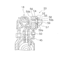
- FIG. 2 is a partial view of FIG. 1.
- FIG. 2 is an enlarged partial view of FIG. 1.
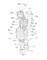
- FIG. 1 is a cross-sectional view of a lockup device 1 which is an embodiment of a power transmission device according to the present invention.
- FIG. 1 shows a part of the device (only one side of the rotation axis), and in FIG. 1, on the left side of the device 1, a front cover 2 (partly indicated by a two-dot chain line) to which torque is input from the engine.
- a torque converter main body (only a part of the turbine 3 is shown) including an impeller, a turbine, and a stator is arranged on the right side.
- the inner periphery of the turbine 3 is fixed to the output hub 5 via a rivet 4.
- a spline hole 5a is formed in the inner peripheral portion of the output hub 5, and an input shaft of the transmission is engaged with the spline hole 5a.
- the lockup device 1 is a kind of power transmission device for transmitting power from an engine to a transmission.
- the lock-up device 1 includes a piston 10 and a drive plate (an example of an input side rotating member) 11, a hub flange (an example of an output side rotating member) 12, an intermediate member 14, a plurality of outer peripheral torsion springs 16, and a plurality of Inner torsion spring 17, float member 18, and dynamic damper device 20.
- the lockup device 1 includes an angle restriction unit 22 and a movement restriction unit 24.
- the angle restricting portion 22 restricts the relative rotation angle between the drive plate 11 and the intermediate member 14 to a predetermined angle.
- the movement restricting unit 24 restricts the movement of the float member 18 in the axial direction.
- the piston 10 is a disk-shaped plate, and is disposed on the turbine side (right side in FIG. 1) of the front cover 2.
- the piston 10 is supported by the output hub 5 so as to be relatively rotatable and axially movable.
- the piston 10 moves to the front cover 2 side and thereby rotates integrally with the front cover 2 by frictional engagement.
- the piston 10 has a disc part 10a, a friction material 26, and a cylindrical part 10b.
- the disc portion 10a is disc-shaped and has an opening at the center.
- the disc part 10a has a flat part 10c on the outer periphery.
- a friction material 26 is fixed to the surface of the flat portion 10c on the front cover 2 side.
- the friction material 26 is annular. When the friction material 26 is pressed against the front cover 2, torque is transmitted from the front cover 2 to the piston 10.
- the cylindrical portion 10b extends from the inner peripheral end of the disc portion 10a to the turbine 3 side.
- the cylindrical portion 10b is supported on the outer peripheral surface of the output hub 5 so as to be axially movable and relatively rotatable.
- a seal member 28 is attached to the outer peripheral surface of the output hub 5.
- the seal member 28 seals between the inner peripheral surface of the piston 10 and the output hub 5. Further, the axial movement of the piston 10 toward the turbine 3 is restricted when the tip of the cylindrical portion 10 b comes into contact with the side surface of the stepped portion of the output hub 5.
- the drive plate 11 is a plate that is fixed to the piston 10 and that engages with the outer peripheral side torsion spring 16. Specifically, the drive plate 11 is fixed to the side surface of the piston 10 on the turbine 3 side at the outer peripheral portion of the piston 10.
- the drive plate 11 is formed in a disk shape, and the inner peripheral portion 11 a is fixed to the surface of the piston 10 on the turbine 3 side by a rivet 30.
- the drive plate 11 has a plurality of engaging portions 11b. Specifically, each engaging part 11b is formed by bending the outer peripheral part of the drive plate 11 to the turbine 3 side. Each engaging part 11b is formed at intervals in the circumferential direction. Each engaging portion 11 b is engaged with both ends of each outer peripheral side torsion spring 16.
- the hub flange 12 is a disk-shaped plate, and an inner peripheral end portion is fixed to the output hub 5 by a rivet 4.
- the hub flange 12 has spring accommodating portions 12a that are open at predetermined intervals in the circumferential direction, and an inner peripheral torsion spring 17 is accommodated in the spring accommodating portion 12a.
- a plurality of notches 12 b that open to the outer peripheral side are formed at the outer peripheral end of the hub flange 12. This notch 12b will be described later.
- a cylindrical support portion 12 c is formed on the outer peripheral side of the portion fixed by the rivet 4 in the inner peripheral portion of the hub flange 12.
- the intermediate member 14 is disposed on the turbine 3 side of the piston 10 and is rotatable relative to the drive plate 11 and the hub flange 12.
- the intermediate member 14 has a first intermediate plate 35 and a second intermediate plate 36.
- the hub flange 12 is disposed between the intermediate plates 35 and 36 in the axial direction.
- the first and second intermediate plates 35 and 36 connect the outer peripheral side torsion spring 16 and the inner peripheral side torsion spring 17 in series.
- the second intermediate plate 36 rotates integrally with the first intermediate plate 35.
- the second intermediate plate 36 is fixed to the first intermediate plate 35 by a stop pin 38.
- the first and second intermediate plates 35 and 36 are annular and disk-shaped members disposed between the piston 10 and the turbine 3.
- the first intermediate plate 35 and the second intermediate plate 36 are disposed to face each other with an interval in the axial direction.
- the first intermediate plate 35 is disposed on the turbine 3 side, and the second intermediate plate 36 is disposed on the front cover 2 side.
- the first intermediate plate 35 has a disc portion 35a.
- An angle restricting portion 22 and a movement restricting portion 24 are formed on the outer peripheral portion of the disc portion 35a.
- the angle restriction part 22 and the movement restriction part 24 will be described later.
- the second intermediate plate 36 has a disc-shaped main body portion 36a and a plurality of engaging portions 36b.
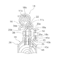
- FIG. 2 is a diagram showing a part extracted from FIG.
- Each engaging portion 36 b is engaged with the outer peripheral side torsion spring 16.
- Each engaging portion 36b extends from the outer peripheral end portion of the main body portion 36a toward the front cover 2 side.
- Each engaging part 36b is arrange
- One outer torsion spring 16 is disposed between the two engaging portions 36b.
- first intermediate plate 35 and the second intermediate plate 36 windows 35c and 36c penetrating in the axial direction are formed at positions corresponding to the spring accommodating portions 12a of the hub flange 12.
- the window portions 35c and 36c are formed to extend in the circumferential direction, and a cut-and-raised portion that is cut and raised in the axial direction is formed on the inner peripheral portion and the outer peripheral portion.
- An inner peripheral torsion spring 17 is disposed in the window portions 35c and 36c of the plates 35 and 36.
- the inner torsion spring 17 is supported at both ends in the circumferential direction and both sides in the radial direction by the windows 35c and 36c. Further, the inner peripheral side torsion spring 17 is restricted from projecting in the radial direction and the axial direction by the cut and raised portions of the window portions 35c and 36c.
- the inner peripheral end surface of the first intermediate plate 35 is in contact with the outer peripheral surface of the support portion 12c of the hub flange 12. With such a configuration, the entire intermediate member 14 is positioned in the radial direction.
- the stop pin 38 passes through the notch 12b of the hub flange 12 in the axial direction.
- the circumferential width of the notch 12b is sufficiently longer than the diameter of the stop pin 38. Therefore, the intermediate member 14 and the hub flange 12 can rotate relative to each other until the stop pin 38 abuts on the circumferential end surface of the notch 12b of the hub flange 12. In other words, the relative rotation between the intermediate member 14 and the hub flange 12 is restricted within a predetermined angular range by the stop pin 38 and the end face of the notch 12b of the hub flange 12.
- first and second connection plates 41, 42 Between the hub flange 12 and the first and second intermediate plates 35 and 36, first and second connection plates 41 and 42 are disposed. More specifically, a first connection plate 41 is disposed between the hub flange 12 and the first intermediate plate 35. A second connection plate 42 is disposed between the hub flange 12 and the second intermediate plate 36. The first and second connection plates 41 and 42 are rotatable relative to the first intermediate plate 35, the second intermediate plate 36, and the hub flange 12. In addition, although the 1st connection plate 41 and the 2nd connection plate 42 are mutually connected, it does not need to be connected.
- the first and second connection plates 41 and 42 connect at least two inner peripheral side torsion springs 17 in series.
- the 1st and 2nd connection plates 41 and 42 are annular and disk-shaped plates, and have a plurality of accommodation holes extended in the peripheral direction.
- the inner circumference side torsion spring 17 is accommodated in each accommodation hole.
- the inner peripheral end surface of the first connecting plate 41 is in contact with the outer peripheral surface of the support portion 12c of the hub flange 12. Thereby, the 1st and 2nd connection plates 41 and 42 are positioned by radial direction.
- the outer peripheral side torsion spring 16 connects the drive plate 11 and the second intermediate plate 36 of the intermediate member 14 so as to be relatively rotatable.
- the inner peripheral side torsion spring 17 is disposed on the inner peripheral side of the outer peripheral side torsion spring 16 and connects the first and second intermediate plates 35 and 36 and the hub flange 12 so as to be relatively rotatable.
- the outer peripheral side torsion spring 16 and the inner peripheral side torsion spring 17 are connected in series by the intermediate member 14.
- a set of two springs of the plurality of inner peripheral side torsion springs 17 are connected in series by first and second connection plates 41 and 42.
- the inner circumference side torsion spring 17 has a large spring 17a and a small spring 17b disposed inside the large spring 17a.
- the small spring 17b is set shorter than the spring length of the large spring 17a. Accordingly, the small spring 17b operates later than the large spring 17a.
- the float member 18 is an annular plate member. As shown in an enlarged view in FIG. 3, the float member 18 includes a disk portion 18 a and a support portion 18 b.
- the disc portion 18a is annular and disc-shaped.
- the inner peripheral end of the disc portion 18a has a positioning portion 18c that is bent toward the front cover 2 and formed in a cylindrical shape.
- the support portion 18b is formed by bending the outer peripheral portion of the disc portion 18a to the front cover 2 side.
- the support portion 18b has a cylindrical shape, and the outer peripheral side torsion spring 16 is accommodated in the support portion 18b.
- the float member 18 is rotatable relative to the drive plate 11, the hub flange 12, and the intermediate member 14. Further, the support portion 18 b of the float member 18 and the outer peripheral side torsion spring 16 are not engaged. Therefore, although the float member 18 and the outer peripheral side torsion spring 16 may be rotated by sliding, they do not rotate synchronously.
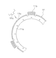
- FIGS. 4 is a front partial view of the drive plate 11 viewed from the turbine 3 side
- FIG. 5 is a front partial view of the first intermediate plate 35 viewed from the turbine 3 side
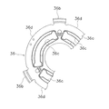
- FIG. 6 illustrates the second intermediate plate 36 of the front cover 2. It is the front fragmentary view seen from the side.
- the angle restricting portion 22 is formed by the drive plate 11 and the first and second intermediate plates 35 and 36.
- the drive plate 11 is formed with a plurality of claws 11c protruding toward the turbine 3 on the inner peripheral side of the engaging portion 11b.
- the second intermediate plate 36 has a notch 36d that is long in the circumferential direction between the two engaging portions 36b.
- a plurality of stopper portions 35 b are formed on the outer peripheral portion of the first intermediate plate 35 so as to be offset from the disc portion 35 a toward the front cover 2. .
- the stopper portion 35b and the engaging portion 36b of the second intermediate plate 35 are provided at the same position in the circumferential direction, and the width in the circumferential direction is the same.
- the claw 11c of the drive plate 11 passes through the notch 36d of the second intermediate plate 36 in the axial direction, and further extends to a position where it overlaps with the stopper portion 35b of the first intermediate plate 35 in the axial direction.
- the drive plate 11 and the first and second intermediate plates 35 and 36 can be rotated relative to each other until the claw 11c contacts the circumferential end surfaces of the engaging portion 36b and the stopper portion 35b. is there.
- the claw 11c comes into contact with the engaging portion 36b and the stopper portion 35b, it becomes a bending point of torsional characteristics.
- the movement restricting portion 24 is formed by the outer peripheral portion of the first intermediate plate 35. Specifically, a contact portion 35e is formed in a portion where the stopper portion 35b is not formed on the outer peripheral portion of the first intermediate plate 35. As shown in FIG. 3, the contact portion 35e is formed offset from the disc portion 35a to the turbine 3 side. The contact portion 35e contacts the side surface of the float member 18 on the front cover 2 side, and restricts the axial movement of the float member 18 toward the front cover 2 side.
- a regulating member 45 is fixed by a rivet 46 on the side surface of the first intermediate plate 35 on the turbine 3 side.
- the regulating member 45 is a member that regulates the axial movement of the float member 18 toward the turbine 3 side.
- the restricting member 45 has a first restricting portion 45a, a second restricting portion 45b, and an attaching portion 45c.
- the restricting member 45 is formed from a single annular and disk-shaped plate.
- the first restricting portion 45a is disposed at a distance from the first intermediate plate 35 in the axial direction. Specifically, the first restricting portion 45 a is disposed between the first intermediate plate 35 and the turbine 3. The first restricting portion 45a extends from the second restricting portion 45b to the outer peripheral side.
- the second restricting portion 45b extends from the inner peripheral end of the first restricting portion 45a toward the first intermediate plate 35, and is formed in a cylindrical shape.
- the positioning portion 18c of the float member 18 is supported on the outer peripheral surface of the second restricting portion 45b.
- the mounting portion 45 c extends from the second restricting portion 45 b to the inner peripheral side and is fixed to the first intermediate plate 35.
- the movement of the float member 18 in the axial direction is restricted by the movement restricting portion 24 and the first restricting portion 45a of the restricting member 45. Further, the float member 18 and the dynamic damper device 20 are positioned in the radial direction by the second restricting portion 45b.
- the dynamic damper device 20 is attached to the inner peripheral portion of the float member 18 by a rivet 50. As shown in FIG. 7, the dynamic damper device 20 includes a base plate 52, a first inertia member 54, a second inertia member 55, a first lid member 56, a second lid member 57, and a plurality of coil springs 58. And a stop pin 59.
- the base plate 52 has an annular shape and is fixed to the float member 18 with a rivet 50. Although details are omitted, the base plate 52 has a plurality of accommodating portions arranged side by side in the circumferential direction. Each accommodating portion extends in the circumferential direction, and a plurality of elongated holes extending in the circumferential direction are formed between the accommodating portions.
- the first and second inertia members 54 and 55 are disposed so as to sandwich the base plate 52 in the axial direction, and are rotatable relative to the base plate 52.
- the first and second inertia members 54 and 55 have a plurality of accommodating portions. Each accommodating portion is disposed at a position corresponding to each accommodating portion of the base plate 52. Further, the first and second inertia members 54 and 55 have a through hole at a position corresponding to the center position in the circumferential direction of the long hole of the base plate 52.
- the first and second lid members 56 and 57 are annular and are arranged on the outer sides in the axial direction of the first and second inertia members 54 and 55. Through holes are formed in the first and second lid members 56 and 57 at positions corresponding to the through holes of the first and second inertia members 54 and 55.
- the plurality of coil springs 58 are accommodated in the accommodating portions of the base plate 52 and the inertia members 54 and 55, respectively. Then, both end portions of the coil spring 58 are in contact with the end portions in the circumferential direction of the accommodating portions of the base plate 52 and the inertia members 54 and 55.
- the stop pin 59 has a large-diameter barrel portion 59a at the axial center and a small-diameter barrel portion 59b on both sides thereof.
- the large-diameter body portion 59a is larger in diameter than the through holes of both inertia members 54 and 55, and smaller in diameter than the long hole diameter (diameter direction dimension) of the base plate 52. Further, the large diameter body portion 59 a is formed slightly thicker than the base plate 52.
- the small diameter body portion 59b is inserted through the through holes of both inertia members 54 and 55 and the through holes of both lid members 56 and 57. And the inertia members 54 and 55 and the both lid members 56 and 57 are being fixed to the axial direction both sides of the base plate 52 by crimping the head of the small diameter trunk
- the base plate 52 can be rotated relative to the inertia members 54 and 55 and the lid members 56 and 57 within a range in which the stop pin 59 can move through the long hole of the base plate 52. And when the large diameter trunk
- the lockup device 1 transmits torque and absorbs and attenuates rotational speed fluctuations input from the front cover 2. Specifically, when torsional vibration occurs in the lockup device 1, the outer peripheral side torsion spring 16 and the inner peripheral side torsion spring 17 operate in series between the drive plate 11 and the hub flange 12. The rotational speed fluctuation is attenuated by the operation of these torsion springs 16 and 17 and the frictional resistance (hysteresis torque) of each part.
- the inertia elements including the inertia members 54 and 55 and the lid members 56 and 57 act in a direction opposite to the direction of vibration due to fluctuations in the rotational speed. It will be.
- the rotational speed fluctuation of the outer peripheral side torsion spring 16 is directly attenuated from the float member 18, and the rotational speed fluctuation transmitted to the transmission side by the frictional force generated between the float member 18 and the regulating member 45 is directly applied. Attenuate.
- the claw 11c of the drive plate 11 is engaged with the engaging portion 36b of the second intermediate plate 36 and the first intermediate plate 35. It abuts against the stopper portion 35b. Therefore, when the input torque is T1 or more, the outer peripheral side torsion spring 16 does not operate, and only the large spring 17a of the inner peripheral side torsion spring 17 operates. For this reason, when the torsion angle is equal to or greater than ⁇ 1, the torsional characteristics have a medium rigidity with higher rigidity than the low rigidity torsional characteristics of the torsion angles 0 to ⁇ 1.
- the inner torsion spring 17 compresses the small spring 17b in addition to the large spring 17a. For this reason, when the torsion angle is equal to or greater than ⁇ 2, the torsional characteristics are higher and higher rigidity than the medium rigidity torsional characteristics of the torsion angles ⁇ 1 to ⁇ 2.
- stop pin 38 comes into contact with the circumferential end surface of the notch 12b formed on the outer periphery of the hub flange 12, and the operation of all the torsion springs 16 and 17 is stopped.
- the present invention is applied to the lockup device provided with the dynamic damper device 20, but the present invention can be similarly applied to a lockup device provided with no dynamic damper device. .
- the intermediate member 14 is provided with the engaging portion 36b that engages with the outer peripheral torsion spring 16 on the second intermediate plate 36 side, but this engaging portion is provided on the first intermediate plate side. It may be provided.
- the first intermediate plate 135 has a stopper portion 135b and an abutting portion 135e formed on the outer peripheral portion in the same manner as in the above embodiment.
- the stopper part 135b is further extended to the outer peripheral side, and the front-end
- the engaging portion 135f is in contact with the end surface of the outer peripheral side torsion spring 16.
- the second intermediate plate 136 has only a notch 136d formed at the outer peripheral end portion, and no engaging portion in the above embodiment.
- the claw 11c of the drive plate 11 passes through the notch 136d in the axial direction.
- the movement of the float member in the axial direction is restricted and the torsional characteristics are multistaged with a simple configuration. Can do.
Landscapes
- Engineering & Computer Science (AREA)
- General Engineering & Computer Science (AREA)
- Mechanical Engineering (AREA)
- Physics & Mathematics (AREA)
- Acoustics & Sound (AREA)
- Aviation & Aerospace Engineering (AREA)
- Mechanical Operated Clutches (AREA)
Abstract
ロックアップ装置において、フロート部材の軸方向の移動規制及び捩り特性の多段化を、簡単な構成で実現する。この装置は、ドライブプレート(11)と、ハブフランジ(12)と、外周側及び内周側のトーションスプリング(16,17)と、外周側と内周側のトーションスプリング(16,17)を直列に連結する中間部材(14)と、フロート部材(18)と、角度規制部(22)と、移動規制部(24)と、を備えている。フロート部材(18)は、外周側トーションスプリング(16)に相対回転可能であり、外周側トーションスプリング(16)の径方向の移動を規制する。角度規制部(22)は、ドライブプレート(11)及び中間部材(14)に形成され、ドライブプレート(11)と中間部材(14)との相対回転角度を所定の角度に規制する。移動規制部(24)は、中間部材(14)に形成され、フロート部材(18)の軸方向の移動を規制する。
Description
本発明は、動力伝達装置、特に、エンジンからトランスミッションに動力を伝達するための動力伝達装置に関する。
トルクコンバータにおいては、燃費低減のためにロックアップ装置が設けられている。ロックアップ装置は、フロントカバーとタービンとの間に配置されており、フロントカバーとタービンとを機械的に連結して両者の間でトルクを直接伝達するものである。
ロックアップ装置は、例えば特許文献1に示されるように、ピストンとダンパ機構とを有している。ピストンは、摩擦部材を有しており、油圧の作用によってフロントカバーに押し付けられ、フロントカバーからトルクが伝達される。また、ダンパ機構は、それぞれ複数の外周側トーションスプリング及び内周側トーションスプリングと、外周側トーションスプリングと内周側トーションスプリングとを連結する中間部材と、を有している。
また、外周側トーションスプリングの径方向の移動を規制するために、フロート部材が設けられている。フロート部材は、ピストンと、ピストンに固定されたドライブプレートと、によって軸方向の移動が規制されている。
特許文献1に示されたようなロックアップ装置では、外周及び内周にトーションスプリングを配置し、捩り特性を多段化している。このため、例えば外周側のトーションスプリングの圧縮を、所定の捩り角度で停止させる必要がある。このため、一般的には、ストップピン等を用いたストッパ機構が必要になる。
本発明の課題は、フロート部材の軸方向の移動規制及び捩り特性の多段化を、簡単な構成で実現することにある。
(1)本発明の一側面に係る動力伝達装置は、エンジンからトランスミッションに動力を伝達するための装置であって、エンジンからの動力が入力される入力側回転部材と、トランスミッションに動力を出力する出力側回転部材と、外周側弾性部材及び内周側弾性部材と、中間部材と、フロート部材と、角度規制部と、移動規制部と、を備えている。外周側弾性部材及び内周側弾性部材は入力側回転部材と出力側回転部材とを相対回転可能に連結する。中間部材は、入力側回転部材及び出力側回転部材に相対回転可能に配置され、外周側弾性部材と内周側弾性部材とを直列に作動させる。フロート部材は、入力側回転部材、出力側回転部材、中間部材、及び外周側弾性部材に相対回転可能であり、外周側弾性部材の径方向の移動を規制する。角度規制部は、入力側回転部材及び中間部材に形成され、入力側回転部材と中間部材との相対回転角度を所定の角度に規制する。移動規制部は、中間部材に形成され、フロート部材の軸方向の移動を規制する。
この装置では、入力側回転部材に入力された動力は、外周側弾性部材及び内周側弾性部材を介して出力側回転部材に伝達される。このとき、外周側弾性部材と内周側弾性部材とは中間部材によって直列に作動する。このとき、外周側弾性部材及び内周側弾性部材の作動によってトランスミッション側に伝達される回転速度変動が抑えられる。
ここでは、中間部材を利用して、入力側回転部材と中間部材との相対回転角度を規制する角度規制部と、フロート部材の軸方向の移動を規制する移動規制部と、を構成している。したがって、簡単な構成で、捩り特性の多段化及びフロート部材の移動規制を実現できる。
(2)本発明の別の側面に係る動力伝達装置では、入力側回転部材は円板状のドライブプレートを有し、中間部材はドライブプレートに対向して配置された円板状の第1中間プレートを有している。そして、角度規制部は爪とストッパ部とを有する。爪は、ドライブプレートに形成され、第1中間プレート側に延びている。ストッパ部は、第1中間プレートに形成され、ドライブプレートの爪が当接可能である。
(3)本発明のさらに別の側面に係る動力伝達装置では、移動規制部は、第1中間プレートのストッパ部が形成されていない部分に形成され、フロート部材の側面に当接する当接部を有している。
(4)本発明のさらに別の側面に係る動力伝達装置では、中間部材は、ドライブプレートと第1中間プレートとの間に第1中間プレートと軸方向に対向して配置され、第1中間プレートに相対回転不能にかつ軸方向移動不能に固定された第2中間プレートをさらに有している。そして、内周側弾性部材は第1中間プレート及び第2中間プレートによって径方向及び軸方向に支持されている。
(5)本発明のさらに別の側面に係る動力伝達装置では、出力側回転部材は、円板状のプレートであり、第1中間プレートと第2中間プレートとの軸方向間に配置され、内周側弾性部材を収容する収容部を有している。
(6)本発明のさらに別の側面に係る動力伝達装置では、フロート部材は回転時に外周側弾性部材に対して摺動するように配置されている。また、この装置はダンパ装置をさらに備え、ダンパ装置は、フロート部材に対して相対回転自在なイナーシャ部材を含み、フロート部材に装着されている。
ここでは、イナーシャ部材を有するダンパ装置が、外周側弾性部材に対して自由に回転するフロート部材に装着されている。すなわち、フロート部材は外周側弾性部材に係合されていない。このため、従来装置で発生していたダンパ装置の共振が発生せず、特に低回転数域での回転速度変動をより抑えることができる。
(7)本発明のさらに別の側面に係る動力伝達装置では、ダンパ装置は、フロート部材に固定されたベースプレートと、ベースプレートに対して相対回転自在に配置されたイナーシャ部材と、ベースプレートとイナーシャ部材とを連結するダンパと、を有する。
(8)本発明のさらに別の側面に係る動力伝達装置では、中間部材に装着され、フロート部材が軸方向の一方に移動するのを規制する規制部材をさらに備えている。
(9)本発明のさらに別の側面に係る動力伝達装置では、規制部材は、固定部と、径方向支持部と、軸方向支持部と、を有する。固定部は中間部材に固定される。径方向支持部は、固定部の外周端部から軸方向に延びる筒状に形成され、フロート部材及びダンパ装置を径方向に位置決めする。軸方向支持部は、径方向支持部の先端部から外周側に延び、フロート部材及びダンパ装置を軸方向に位置決めする。
(10)本発明のさらに別の側面に係る動力伝達装置では、外周側弾性部材は回転方向に延びるコイルスプリングである。また、フロート部材は、コイルスプリングの外周部に接触可能であり、コイルスプリングの径方向の移動を規制する。
以上のような本発明では、弾性部材の径方向の移動を規制するフロート部材が設けられた装置において、簡単な構成で、フロート部材の軸方向の移動規制及び捩り特性の多段化を実現することができる。
図1は、本発明に係る動力伝達装置の一実施形態であるロックアップ装置1の断面図である。図1では、装置の一部(回転軸線の一方側のみ)を示しており、図1において、装置1の左側には、エンジンからトルクが入力されるフロントカバー2(二点鎖線で一部を示している)が配置され、右側にはインペラ、タービン、ステータを含むトルクコンバータ本体(タービン3の一部のみを示している)が配置されている。タービン3は、内周部がリベット4を介して出力ハブ5に固定されている。出力ハブ5の内周部にはスプライン孔5aが形成されており、このスプライン孔5aにトランスミッションの入力軸が係合される。
[全体構成]
ロックアップ装置1は、エンジンからトランスミッションに動力を伝達するための動力伝達装置の一種である。ロックアップ装置1は、ピストン10及びドライブプレート(入力側回転部材の一例)11と、ハブフランジ(出力側回転部材の一例)12と、中間部材14と、複数の外周側トーションスプリング16と、複数の内周側トーションスプリング17と、フロート部材18と、ダイナミックダンパ装置20と、を備えている。
ロックアップ装置1は、エンジンからトランスミッションに動力を伝達するための動力伝達装置の一種である。ロックアップ装置1は、ピストン10及びドライブプレート(入力側回転部材の一例)11と、ハブフランジ(出力側回転部材の一例)12と、中間部材14と、複数の外周側トーションスプリング16と、複数の内周側トーションスプリング17と、フロート部材18と、ダイナミックダンパ装置20と、を備えている。
また、このロックアップ装置1は、角度規制部22と、移動規制部24と、を有している。角度規制部22は、ドライブプレート11と中間部材14との相対回転角度を所定の角度に規制する。移動規制部24は、フロート部材18の軸方向の移動を規制する。
[ピストン10]
ピストン10は、円板状のプレートであり、フロントカバー2のタービン側(図1の右側)に配置されている。ピストン10は、出力ハブ5に相対回転可能かつ軸方向移動可能に支持されている。ピストン10は、フロントカバー2側に移動することによって、フロントカバー2と摩擦係合して一体的に回転する。
ピストン10は、円板状のプレートであり、フロントカバー2のタービン側(図1の右側)に配置されている。ピストン10は、出力ハブ5に相対回転可能かつ軸方向移動可能に支持されている。ピストン10は、フロントカバー2側に移動することによって、フロントカバー2と摩擦係合して一体的に回転する。
ピストン10は、円板部10a、摩擦材26、及び筒状部10b、を有している。円板部10aは、円板状であって、中央に開口を有している。円板部10aは外周部に平坦部10cを有している。この平坦部10cのフロントカバー2側の面に、摩擦材26が固定されている。摩擦材26は環状である。この摩擦材26がフロントカバー2に押し付けられることによって、フロントカバー2からピストン10にトルクが伝達される。
筒状部10bは、円板部10aの内周端からタービン3側に延びている。この筒状部10bが、出力ハブ5の外周面に軸方向移動自在及び相対回転自在に支持されている。
なお、出力ハブ5の外周面には、シール部材28が装着されている。このシール部材28によって、ピストン10の内周面と出力ハブ5との間がシールされている。また、ピストン10は、筒状部10bの先端が出力ハブ5の段付き部の側面に当接することによって、タービン3側への軸方向移動が規制されている。
[ドライブプレート11]
ドライブプレート11は、ピストン10に固定されており、外周側トーションスプリング16と係合するプレートである。詳細には、ドライブプレート11は、ピストン10の外周部において、ピストン10のタービン3側の側面に固定されている。
ドライブプレート11は、ピストン10に固定されており、外周側トーションスプリング16と係合するプレートである。詳細には、ドライブプレート11は、ピストン10の外周部において、ピストン10のタービン3側の側面に固定されている。
ドライブプレート11は、円板状に形成されており、内周部11aがピストン10のタービン3側の面にリベット30により固定されている。ドライブプレート11は、複数の係合部11bを有している。具体的には、各係合部11bは、ドライブプレート11の外周部をタービン3側に折り曲げることによって形成されている。各係合部11bは、周方向に間隔をあけて形成されている。各係合部11bは各外周側トーションスプリング16の両端に係合している。
[ハブフランジ12]
ハブフランジ12は、円板状のプレートであり、内周端部が出力ハブ5にリベット4により固定されている。ハブフランジ12は、円周方向に所定の間隔で開口であるスプリング収容部12aを有しており、このスプリング収容部12aに内周側トーションスプリング17が収容されている。また、ハブフランジ12の外周端部には、外周側に開く複数の切欠き12bが形成されている。この切欠き12bについては後述する。
ハブフランジ12は、円板状のプレートであり、内周端部が出力ハブ5にリベット4により固定されている。ハブフランジ12は、円周方向に所定の間隔で開口であるスプリング収容部12aを有しており、このスプリング収容部12aに内周側トーションスプリング17が収容されている。また、ハブフランジ12の外周端部には、外周側に開く複数の切欠き12bが形成されている。この切欠き12bについては後述する。
また、ハブフランジ12の内周部において、リベット4によって固定された部分の外周側には、筒状の支持部12cが形成されている。
[中間部材14]
中間部材14は、ピストン10のタービン3側に配置されており、ドライブプレート11及びハブフランジ12と相対回転可能である。中間部材14は、第1中間プレート35と第2中間プレート36とを有している。これらの中間プレート35,36の軸方向間に、ハブフランジ12が配置されている。
中間部材14は、ピストン10のタービン3側に配置されており、ドライブプレート11及びハブフランジ12と相対回転可能である。中間部材14は、第1中間プレート35と第2中間プレート36とを有している。これらの中間プレート35,36の軸方向間に、ハブフランジ12が配置されている。
第1及び第2中間プレート35,36は、外周側トーションスプリング16と内周側トーションスプリング17とを直列に連結する。第2中間プレート36は、第1中間プレート35と一体的に回転する。詳細には、第2中間プレート36は、ストップピン38によって第1中間プレート35に固定されている。
第1及び第2中間プレート35,36はピストン10とタービン3との間に配置された環状かつ円板状の部材である。第1中間プレート35と第2中間プレート36とは、軸方向に間隔をあけて対向して配置されている。第1中間プレート35がタービン3側に配置され、第2中間プレート36がフロントカバー2側に配置されている。
第1中間プレート35は円板部35aを有する。円板部35aの外周部には、角度規制部22及び移動規制部24が形成されている。角度規制部22及び移動規制部24については後述する。
図2に示すように、第2中間プレート36は、円板状の本体部36aと、複数の係合部36bとを有している。図2は、図1の一部を抽出して示した図である。各係合部36bは、外周側トーションスプリング16に係止する。各係合部36bは、本体部36aの外周端部からフロントカバー2側に向かって延びている。各係合部36bは円周方向に互いに間隔をあけて配置されている。2つの係合部36bの間に、1つの外周側トーションスプリング16が配置されている。
第1中間プレート35及び第2中間プレート36において、ハブフランジ12のスプリング収容部12aに対応する位置には、軸方向に貫通する窓部35c,36cが形成されている。窓部35c,36cは、円周方向に延びて形成されており、内周部と外周部には、軸方向に切り起こされた切り起こし部が形成されている。この両プレート35,36の窓部35c,36c内に内周側トーションスプリング17が配置されている。そして、内周側トーションスプリング17は窓部35c,36cによって円周方向両端及び径方向両側が支持されている。さらに、内周側トーションスプリング17は窓部35c,36cの切り起こし部によって径方向及び軸方向への飛び出しが規制されている。
なお、第1中間プレート35の内周端面は、ハブフランジ12の支持部12cの外周面に当接している。このような構成によって、中間部材14全体が径方向に位置決めされている。
ここで、ストップピン38は、ハブフランジ12の切欠き12bを軸方向に貫通している。そして、切欠き12bの円周方向の幅は、ストップピン38の径に比較して十分に長く形成されている。したがって、中間部材14とハブフランジ12とは、ストップピン38がハブフランジ12の切欠き12bの円周方向の端面に当接するまで、相対回転が可能である。言い換えれば、中間部材14とハブフランジ12との相対回転は、ストップピン38とハブフランジ12の切欠き12bの端面とによって所定の角度範囲に規制されている。
[第1及び第2連結プレート41,42]
ハブフランジ12と第1及び第2中間プレート35,36との間には、第1及び第2連結プレート41,42が配置されている。より詳細には、ハブフランジ12と第1中間プレート35との間には第1連結プレート41が配置されている。また、ハブフランジ12と第2中間プレート36との間には第2連結プレート42が配置されている。第1及び第2連結プレート41,42は、第1中間プレート35、第2中間プレート36、及びハブフランジ12と相対回転可能である。なお、第1連結プレート41と第2連結プレート42とは互いに連結されているが、連結されていなくてもよい。
ハブフランジ12と第1及び第2中間プレート35,36との間には、第1及び第2連結プレート41,42が配置されている。より詳細には、ハブフランジ12と第1中間プレート35との間には第1連結プレート41が配置されている。また、ハブフランジ12と第2中間プレート36との間には第2連結プレート42が配置されている。第1及び第2連結プレート41,42は、第1中間プレート35、第2中間プレート36、及びハブフランジ12と相対回転可能である。なお、第1連結プレート41と第2連結プレート42とは互いに連結されているが、連結されていなくてもよい。
第1及び第2連結プレート41,42は、少なくとも2つの内周側トーションスプリング17を直列に連結する。第1及び第2連結プレート41,42は、環状かつ円板状のプレートであり、周方向に延びる複数の収容孔を有している。この各収容孔に内周側トーションスプリング17が収容されている。
なお、第1連結プレート41の内周端面は、ハブフランジ12の支持部12cの外周面に当接している。これにより、第1及び第2連結プレート41,42は径方向に位置決めされている。
[外周側及び内周側トーションスプリング16,17]
外周側トーションスプリング16は、ドライブプレート11と中間部材14の第2中間プレート36とを相対回転可能に連結する。内周側トーションスプリング17は、外周側トーションスプリング16の内周側に配置され、第1及び第2中間プレート35,36とハブフランジ12とを相対回転可能に連結する。前述のように、外周側トーションスプリング16と内周側トーションスプリング17とは、中間部材14によって直列に連結される。また、複数の内周側トーションスプリング17のうちの1組2個のスプリングは、第1及び第2連結プレート41,42によって直列に連結される。
外周側トーションスプリング16は、ドライブプレート11と中間部材14の第2中間プレート36とを相対回転可能に連結する。内周側トーションスプリング17は、外周側トーションスプリング16の内周側に配置され、第1及び第2中間プレート35,36とハブフランジ12とを相対回転可能に連結する。前述のように、外周側トーションスプリング16と内周側トーションスプリング17とは、中間部材14によって直列に連結される。また、複数の内周側トーションスプリング17のうちの1組2個のスプリングは、第1及び第2連結プレート41,42によって直列に連結される。
内周側トーションスプリング17は、大スプリング17aと、大スプリング17aの内部に配置された小スプリング17bと、を有している。小スプリング17bは大スプリング17aのスプリング長より短く設定されている。したがって、小スプリング17bは、大スプリング17aより遅れて作動することになる。
[フロート部材18]
フロート部材18は、環状のプレート部材である。図3に拡大して示すように、フロート部材18は、円板部18aと、支持部18bと、を有する。円板部18aは環状かつ円板状である。円板部18aの内周端は、フロントカバー2側に折り曲げられ、筒状に形成された位置決め部18cを有している。支持部18bは、円板部18aの外周部をフロントカバー2側に折り曲げて形成されている。支持部18bは筒状であり、この支持部18bに外周側トーションスプリング16が収容されている。
フロート部材18は、環状のプレート部材である。図3に拡大して示すように、フロート部材18は、円板部18aと、支持部18bと、を有する。円板部18aは環状かつ円板状である。円板部18aの内周端は、フロントカバー2側に折り曲げられ、筒状に形成された位置決め部18cを有している。支持部18bは、円板部18aの外周部をフロントカバー2側に折り曲げて形成されている。支持部18bは筒状であり、この支持部18bに外周側トーションスプリング16が収容されている。
フロート部材18は、ドライブプレート11、ハブフランジ12、及び中間部材14に対して相対回転可能である。また、フロート部材18の支持部18bと外周側トーションスプリング16とは係合していない。したがって、フロート部材18と外周側トーションスプリング16とは、摺動によって連れ回りすることはあるが、同期して回転しない。
[角度規制部22]
角度規制部22を、図2~図6を用いて説明する。なお、図4はドライブプレート11をタービン3側に視た正面部分図、図5は第1中間プレート35をタービン3側から視た正面部分図、図6は第2中間プレート36をフロントカバー2側から視た正面部分図である。
角度規制部22を、図2~図6を用いて説明する。なお、図4はドライブプレート11をタービン3側に視た正面部分図、図5は第1中間プレート35をタービン3側から視た正面部分図、図6は第2中間プレート36をフロントカバー2側から視た正面部分図である。
図2~図6に示すように、角度規制部22は、ドライブプレート11と、第1及び第2中間プレート35,36とによって形成されている。具体的には、ドライブプレート11には、係合部11bの内周側において、タービン3側に突出する複数の爪11cが形成されている。一方、図6に示すように、第2中間プレート36には、2つの係合部36bの間に、円周方向に長い切欠き36dが形成されている。また、図3及び図5に示すように、第1中間プレート35の外周部には、円板部35aよりもフロントカバー2側にオフセットして形成された複数のストッパ部35bが形成されている。このストッパ部35bと第2中間プレート35の係合部36bとは、円周方向において同じ位置に設けられており、かつ円周方向の幅は同じである。
そして、ドライブプレート11の爪11cは、第2中間プレート36の切欠き36dを軸方向に通過し、さらに第1中間プレート35のストッパ部35bと軸方向において重なる位置まで延びている。
以上のような構成では、ドライブプレート11と第1及び第2中間プレート35,36とは、爪11cが係合部36b及びストッパ部35bの円周方向の端面に当接するまで相対回転が可能である。言い換えれば、爪11cが係合部36b及びストッパ部35bに当接したときに、捩り特性の屈曲点になる。
[移動規制部24及び規制部材45]
移動規制部24は、第1中間プレート35の外周部によって形成されている。具体的には、第1中間プレート35の外周部において、ストッパ部35bが形成されていない部分に当接部35eが形成されている。当接部35eは、図3に示すように、円板部35aからタービン3側にオフセットして形成されている。そして、この当接部35eが、フロート部材18のフロントカバー2側の側面に当接し、フロート部材18のフロントカバー2側への軸方向の移動を規制している。
移動規制部24は、第1中間プレート35の外周部によって形成されている。具体的には、第1中間プレート35の外周部において、ストッパ部35bが形成されていない部分に当接部35eが形成されている。当接部35eは、図3に示すように、円板部35aからタービン3側にオフセットして形成されている。そして、この当接部35eが、フロート部材18のフロントカバー2側の側面に当接し、フロート部材18のフロントカバー2側への軸方向の移動を規制している。
また、第1中間プレート35のタービン3側の側面には、規制部材45がリベット46により固定されている。規制部材45は、フロート部材18のタービン3側への軸方向の移動を規制する部材である。図3に示すように、規制部材45は、第1規制部45aと第2規制部45bと、取付部45cとを有している。なお、規制部材45は、1枚の環状かつ円板状のプレートから形成されている。
第1規制部45aは、軸方向において第1中間プレート35と間隔をあけて配置されている。詳細には、第1規制部45aは、第1中間プレート35とタービン3との間に配置されている。第1規制部45aは、第2規制部45bから外周側に延びている。
第2規制部45bは、第1規制部45aの内周端から第1中間プレート35に向かって延び、筒状に形成されている。この第2規制部45bの外周面に、フロート部材18の位置決め部18cが支持されている。
取付部45cは、第2規制部45bから内周側に延び、第1中間プレート35に固定されている。
以上のように、移動規制部24と規制部材45の第1規制部45aとによって、フロート部材18の軸方向の移動が規制されている。また、第2規制部45bによって、フロート部材18及びダイナミックダンパ装置20が径方向に位置決めされている。
[ダイナミックダンパ装置20]
ダイナミックダンパ装置20は、フロート部材18の内周部にリベット50によって取り付けられている。図7に示すように、ダイナミックダンパ装置20は、ベースプレート52と、第1イナーシャ部材54と、第2イナーシャ部材55と、第1蓋部材56と、第2蓋部材57と、複数のコイルスプリング58と、ストップピン59と、を有している。
ダイナミックダンパ装置20は、フロート部材18の内周部にリベット50によって取り付けられている。図7に示すように、ダイナミックダンパ装置20は、ベースプレート52と、第1イナーシャ部材54と、第2イナーシャ部材55と、第1蓋部材56と、第2蓋部材57と、複数のコイルスプリング58と、ストップピン59と、を有している。
ベースプレート52は、環状であり、フロート部材18にリベット50により固定されている。詳細は省略するが、ベースプレート52は、円周方向に並べて配置された複数の収容部を有している。各収容部は円周方向に延び、各収容部の間には、複数の円周方向に延びる長孔が形成されている。
第1及び第2イナーシャ部材54,55は、ベースプレート52を軸方向において挟むように配置され、ベースプレート52に対して相対回転可能である。第1及び第2イナーシャ部材54,55は複数の収容部を有している。各収容部は、ベースプレート52の各収容部に対応する位置に配置されている。また、第1及び第2イナーシャ部材54,55は、ベースプレート52の長孔の円周方向中央位置に対応する位置に貫通孔を有している。
第1及び第2蓋部材56,57は、環状であって、第1及び第2イナーシャ部材54,55の軸方向外側に配置されている。第1及び第2蓋部材56,57には、第1及び第2イナーシャ部材54,55の貫通孔に対応する位置に貫通孔が形成されている。
複数のコイルスプリング58は、それぞれベースプレート52及び両イナーシャ部材54,55の収容部に収容されている。そして、コイルスプリング58の両端部はベースプレート52及び両イナーシャ部材54,55の収容部の円周方向端部に当接している。
ストップピン59は、軸方向の中央部に大径胴部59aを有し、その両側に小径胴部59bを有している。
大径胴部59aは、両イナーシャ部材54,55の貫通孔より大径で、かつベースプレート52の長孔の径(径方向寸法)よりも小径である。また、大径胴部59aの厚みは、ベースプレート52の厚みより若干厚く形成されている。
小径胴部59bは両イナーシャ部材54,55の貫通孔及び両蓋部材56,57の貫通孔を挿通している。そして、小径胴部59bの頭部をかしめることによって、ベースプレート52の軸方向両側にイナーシャ部材54,55及び両蓋部材56,57が固定されている。
以上のような構成により、ベースプレート52は、両イナーシャ部材54,55及び両蓋部材56,57に対して、ストップピン59がベースプレート52の長孔で移動し得る範囲で相対回転が可能である。そして、ストップピン59の大径胴部59aが長孔の端部に当接することによって、両者の相対回転が禁止される。
[動作]
ロックアップ装置1がオン(トルク伝達状態)になると、トルクは、フロントカバー2→ピストン10→ドライブプレート11→外周側トーションスプリング16→中間部材14→内周側トーションスプリング17→ハブフランジ12の経路で伝達され、出力ハブ5を介してトランスミッション側に出力される。
ロックアップ装置1がオン(トルク伝達状態)になると、トルクは、フロントカバー2→ピストン10→ドライブプレート11→外周側トーションスプリング16→中間部材14→内周側トーションスプリング17→ハブフランジ12の経路で伝達され、出力ハブ5を介してトランスミッション側に出力される。
ロックアップ装置1においては、トルクを伝達するとともに、フロントカバー2から入力される回転速度変動を吸収・減衰する。具体的には、ロックアップ装置1において捩り振動が発生すると、外周側トーションスプリング16と内周側トーションスプリング17とがドライブプレート11とハブフランジ12との間で直列に作動する。これらのトーションスプリング16,17の作動及び各部の摩擦抵抗(ヒステリシストルク)によって、回転速度変動が減衰される。
[ダイナミックダンパ装置7の動作]
外周側トーションスプリング16が圧縮されると、円周方向の中央部分が径方向外方に膨らむように変形する。また、遠心力によって、外周側トーションスプリング16は径方向外方に移動しようとする。
外周側トーションスプリング16が圧縮されると、円周方向の中央部分が径方向外方に膨らむように変形する。また、遠心力によって、外周側トーションスプリング16は径方向外方に移動しようとする。
以上のような状況では、外周側トーションスプリング16の外周部とフロート部材18の支持部18bの内周面とが摺動し、両者の間に摩擦抵抗が生じる。このため、フロート部材18は、外周側トーションスプリング16の回転方向と同方向に、外周側トーションスプリング16の捩じり角度のほぼ1/2の回転角度だけ連れ回ることになる。
一方、フロート部材18にはダイナミックダンパ装置20が装着されているので、各イナーシャ部材54,55及び各蓋部材56,57を含む慣性要素が、回転速度変動によって振動する方向と逆方向に作用することになる。これにより、フロート部材18から外周側トーションスプリング16の回転速度変動を直接減衰させるとともに、フロート部材18と規制部材45との間に発生する摩擦力分だけトランスミッション側に伝達される回転速度変動を直接減衰させる。
[捩り特性]
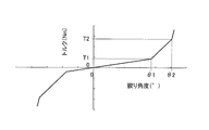
外周側トーションスプリング16及び内周側トーションスプリング17による捩り特性について、図8を用いて説明する。なお、ここでは、捩り角度が正側のみについて説明する。
外周側トーションスプリング16及び内周側トーションスプリング17による捩り特性について、図8を用いて説明する。なお、ここでは、捩り角度が正側のみについて説明する。
まず、入力されるトルクが0~T1の範囲では、外周側トーションスプリング16及び内周側トーションスプリング17の大スプリング17aが圧縮される。この場合の捩り特性は低剛性である。
入力されるトルクがT1になり、ドライブプレート11と中間部材14との相対回転角度がθ1になると、ドライブプレート11の爪11cが第2中間プレート36の係合部36b及び第1中間プレート35のストッパ部35bに当接する。したがって、入力されるトルクがT1以上では、外周側トーションスプリング16は作動せず、内周側トーションスプリング17の大スプリング17aのみが作動することになる。このため、捩り角度がθ1以上では、捩り特性は、捩り角度0~θ1の低剛性の捩り特性よりも高い剛性の中剛性となる。
入力されるトルクがさらに多くなってT2になると、内周側トーションスプリング17において、大スプリング17aに加えて小スプリング17bも圧縮される。このため、捩り角度がθ2以上では、捩り特性は、捩り角度θ1~θ2の中剛性の捩り特性よりも高い剛性の高剛性となる。
そして、最終的には、ストップピン38がハブフランジ12の外周に形成された切欠き12bの円周方向端面に当接し、すべてのトーションスプリング16,17の作動が停止する。
[他の実施形態]
本発明は以上のような実施形態に限定されるものではなく、本発明の範囲を逸脱することなく種々の変形又は修正が可能である。
本発明は以上のような実施形態に限定されるものではなく、本発明の範囲を逸脱することなく種々の変形又は修正が可能である。
(a)前記実施形態では、ダイナミックダンパ装置20が設けられたロックアップ装置に本発明を適用したが、ダイナミックダンパ装置が設けられていないロックアップ装置についても本発明を同様に適用することができる。
(b)ドライブプレート11と第2中間プレート36とによって形成される角度規制部及び移動規制部の構成は、前記実施形態に限定されない。
(c)前記実施形態では、中間部材14において、第2中間プレート36側に、外周側トーションスプリング16に係合する係合部36bを設けたが、この係合部を第1中間プレート側に設けてもよい。
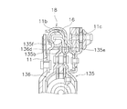
この場合の例を図9に示している。図9において、第1中間プレート135は、外周部に前記実施形態と同様に、ストッパ部135b及び当接部135eが形成されている。そして、ストッパ部135bは、さらに外周側に延び、先端部がフロントカバー2側に折り曲げられて、係合部135fとなっている。この係合部135fが外周側トーションスプリング16の端面に当接している。
なお、この場合の第2中間プレート136は、外周端部に切欠き136dが形成されているだけで、前記実施形態における係合部は形成されていない。そして、この切欠き136dをドライブプレート11の爪11cが軸方向に通過している。
本発明の動力伝達装置では、弾性部材の径方向の移動を規制するフロート部材が設けられた装置において、簡単な構成で、フロート部材の軸方向の移動規制及び捩り特性の多段化を実現することができる。
11 ドライブプレート(入力側回転部材)
11c 爪
12 ハブフランジ(出力側回転部材)
14 中間プレート
16 外周側トーションスプリング
17 内周側トーションスプリング
18 フロート部材
20 ダイナミックダンパ装置
22 角度規制部
24 移動規制部
35 第1中間プレート
35b ストッパ部
52 ベースプレート
54,55 イナーシャ部材
58 コイルスプリング
11c 爪
12 ハブフランジ(出力側回転部材)
14 中間プレート
16 外周側トーションスプリング
17 内周側トーションスプリング
18 フロート部材
20 ダイナミックダンパ装置
22 角度規制部
24 移動規制部
35 第1中間プレート
35b ストッパ部
52 ベースプレート
54,55 イナーシャ部材
58 コイルスプリング
Claims (10)
- エンジンからトランスミッションに動力を伝達するための動力伝達装置であって、
エンジンからの動力が入力される入力側回転部材と、
前記トランスミッションに動力を出力する出力側回転部材と、
前記入力側回転部材と前記出力側回転部材とを相対回転可能に連結する外周側弾性部材及び内周側弾性部材と、
前記入力側回転部材及び前記出力側回転部材に相対回転可能に配置され、前記外周側弾性部材と前記内周側弾性部材とを直列に作動させる中間部材と、
前記入力側回転部材、前記出力側回転部材、前記中間部材、及び前記外周側弾性部材に相対回転可能であり、前記外周側弾性部材の径方向の移動を規制するフロート部材と、
前記入力側回転部材及び前記中間部材に形成され、前記入力側回転部材と前記中間部材との相対回転角度を所定の角度に規制する角度規制部と、
前記中間部材に形成され、前記フロート部材の軸方向の移動を規制する移動規制部と、
を備えた動力伝達装置。 - 前記入力側回転部材は円板状のドライブプレートを有し、
前記中間部材は前記ドライブプレートに対向して配置された円板状の第1中間プレートを有し、
前記角度規制部は、
前記ドライブプレートに形成され、前記第1中間プレート側に延びる爪と、
前記第1中間プレートに形成され、前記ドライブプレートの爪が当接可能なストッパ部と、
を有する、
請求項1に記載の動力伝達装置。 - 前記移動規制部は、前記第1中間プレートの前記ストッパ部形成されていない部分に形成され、前記フロート部材の側面に当接する当接部を有している、請求項2に記載の動力伝達装置。
- 前記中間部材は、前記ドライブプレートと前記第1中間プレートとの間に前記第1中間プレートと軸方向に対向して配置され、前記第1中間プレートに相対回転不能にかつ軸方向移動不能に固定された第2中間プレートをさらに有し、
前記内周側弾性部材は前記第1中間プレート及び前記第2中間プレートによって径方向及び軸方向に支持されている、
請求項3に記載の動力伝達装置。 - 前記出力側回転部材は、円板状のプレートであり、前記第1中間プレートと前記第2中間プレートとの軸方向間に配置され、前記内周側弾性部材を収容する収容部を有している、請求項4に記載の動力伝達装置。
- 前記フロート部材は回転時に前記外周側弾性部材に対して摺動するように配置されており、
前記フロート部材に対して相対回転自在なイナーシャ部材を含み、前記フロート部材に装着されたダンパ装置をさらに備えた、
請求項1から5のいずれかに記載の動力伝達装置。 - 前記ダンパ装置は、
前記フロート部材に固定されたベースプレートと、
前記ベースプレートに対して相対回転自在に配置されたイナーシャ部材と、
前記ベースプレートと前記イナーシャ部材とを連結するダンパと、
を有する、
請求項6に記載の動力伝達装置。 - 前記中間部材に装着され、前記フロート部材が軸方向の一方に移動するのを規制する規制部材をさらに備えた、請求項1から7のいずれかに記載の動力伝達装置。
- 前記規制部材は、
前記中間部材に固定される固定部と、
前記固定部の外周端部から軸方向に延びる筒状に形成され、前記フロート部材及び前記ダンパ装置を径方向に位置決めする径方向支持部と、
前記径方向支持部の先端部から外周側に延び、前記フロート部材及び前記ダンパ装置を軸方向に位置決めするための軸方向支持部と、
を有する、請求項8に記載の動力伝達装置。 - 前記外周側弾性部材は回転方向に延びるコイルスプリングであり、
前記フロート部材は、前記コイルスプリングの外周部に接触可能であり、前記コイルスプリングの径方向の移動を規制する、
請求項1から9のいずれかに記載の動力伝達装置。
Applications Claiming Priority (2)
| Application Number | Priority Date | Filing Date | Title |
|---|---|---|---|
| JP2015-028483 | 2015-02-17 | ||
| JP2015028483A JP2016151306A (ja) | 2015-02-17 | 2015-02-17 | 動力伝達装置 |
Publications (1)
| Publication Number | Publication Date |
|---|---|
| WO2016132886A1 true WO2016132886A1 (ja) | 2016-08-25 |
Family
ID=56692247
Family Applications (1)
| Application Number | Title | Priority Date | Filing Date |
|---|---|---|---|
| PCT/JP2016/053028 Ceased WO2016132886A1 (ja) | 2015-02-17 | 2016-02-02 | 動力伝達装置 |
Country Status (2)
| Country | Link |
|---|---|
| JP (1) | JP2016151306A (ja) |
| WO (1) | WO2016132886A1 (ja) |
Cited By (1)
| Publication number | Priority date | Publication date | Assignee | Title |
|---|---|---|---|---|
| US20230151873A1 (en) * | 2021-11-18 | 2023-05-18 | Schaeffler Technologies AG & Co. KG | Vibration damper with intermediate flange travel stop and torque converter with vibration damper having intermediate flange travel stop |
Citations (3)
| Publication number | Priority date | Publication date | Assignee | Title |
|---|---|---|---|---|
| JP2012122584A (ja) * | 2010-12-10 | 2012-06-28 | Exedy Corp | 流体継手用ロックアップ装置 |
| JP2013117283A (ja) * | 2011-12-05 | 2013-06-13 | Exedy Corp | トルクコンバータのロックアップ装置 |
| JP2015017671A (ja) * | 2013-07-11 | 2015-01-29 | 株式会社エクセディ | トルクコンバータのロックアップ装置 |
-
2015
- 2015-02-17 JP JP2015028483A patent/JP2016151306A/ja active Pending
-
2016
- 2016-02-02 WO PCT/JP2016/053028 patent/WO2016132886A1/ja not_active Ceased
Patent Citations (3)
| Publication number | Priority date | Publication date | Assignee | Title |
|---|---|---|---|---|
| JP2012122584A (ja) * | 2010-12-10 | 2012-06-28 | Exedy Corp | 流体継手用ロックアップ装置 |
| JP2013117283A (ja) * | 2011-12-05 | 2013-06-13 | Exedy Corp | トルクコンバータのロックアップ装置 |
| JP2015017671A (ja) * | 2013-07-11 | 2015-01-29 | 株式会社エクセディ | トルクコンバータのロックアップ装置 |
Cited By (2)
| Publication number | Priority date | Publication date | Assignee | Title |
|---|---|---|---|---|
| US20230151873A1 (en) * | 2021-11-18 | 2023-05-18 | Schaeffler Technologies AG & Co. KG | Vibration damper with intermediate flange travel stop and torque converter with vibration damper having intermediate flange travel stop |
| US12270447B2 (en) * | 2021-11-18 | 2025-04-08 | Schaeffler Technologies AG & Co. KG | Vibration damper with intermediate flange travel stop and torque converter with vibration damper having intermediate flange travel stop |
Also Published As
| Publication number | Publication date |
|---|---|
| JP2016151306A (ja) | 2016-08-22 |
Similar Documents
| Publication | Publication Date | Title |
|---|---|---|
| JP5555784B1 (ja) | ダイナミックダンパ装置 | |
| US9618105B2 (en) | Fluid power transmission device | |
| JP6010476B2 (ja) | ダイナミックダンパ装置 | |
| WO2014123174A1 (ja) | トルクコンバータのロックアップ装置 | |
| JP6530604B2 (ja) | 動力伝達装置 | |
| JP5828030B1 (ja) | トルクコンバータのロックアップ装置 | |
| WO2013118802A1 (ja) | ダイナミックダンパ装置及び流体式動力伝達装置のロックアップ装置 | |
| US20160208862A1 (en) | Damper Disk Assembly | |
| WO2016103890A1 (ja) | 動力伝達装置及びトルクコンバータのロックアップ装置 | |
| WO2014185148A1 (ja) | トルクコンバータのロックアップ装置 | |
| CN113557370A (zh) | 离合器从动盘及离合器 | |
| JP7422618B2 (ja) | ダンパ装置 | |
| WO2016132886A1 (ja) | 動力伝達装置 | |
| JP7263066B2 (ja) | トルク変動抑制装置、及びトルクコンバータ | |
| CN114060462B (zh) | 减振装置 | |
| JP7218221B2 (ja) | トルク変動抑制装置、及びトルクコンバータ | |
| JP7232667B2 (ja) | トルク変動抑制装置 | |
| JP2019090428A5 (ja) | ||
| CN107208768B (zh) | 液力变矩器的锁定装置 | |
| JP6545972B2 (ja) | ダンパーディスク組立体 | |
| JP7449762B2 (ja) | ダンパ装置 | |
| JP2006162054A5 (ja) | ||
| JP5951082B2 (ja) | トルクコンバータのロックアップ装置 | |
| JP7422617B2 (ja) | トルクリミッタ付きダンパ装置 | |
| JP7427472B2 (ja) | スプリングシート及びダンパ装置 |
Legal Events
| Date | Code | Title | Description |
|---|---|---|---|
| 121 | Ep: the epo has been informed by wipo that ep was designated in this application |
Ref document number: 16752273 Country of ref document: EP Kind code of ref document: A1 |
|
| NENP | Non-entry into the national phase |
Ref country code: DE |
|
| 122 | Ep: pct application non-entry in european phase |
Ref document number: 16752273 Country of ref document: EP Kind code of ref document: A1 |