WO2016132875A1 - Exhaust gas purification system for internal combustion engine, internal combustion engine, and exhaust gas purification method for internal combustion engine - Google Patents
Exhaust gas purification system for internal combustion engine, internal combustion engine, and exhaust gas purification method for internal combustion engine Download PDFInfo
- Publication number
- WO2016132875A1 WO2016132875A1 PCT/JP2016/052908 JP2016052908W WO2016132875A1 WO 2016132875 A1 WO2016132875 A1 WO 2016132875A1 JP 2016052908 W JP2016052908 W JP 2016052908W WO 2016132875 A1 WO2016132875 A1 WO 2016132875A1
- Authority
- WO
- WIPO (PCT)
- Prior art keywords
- desulfurization
- sulfur
- exhaust gas
- internal combustion
- combustion engine
- Prior art date
Links
Images


Classifications
-
- B—PERFORMING OPERATIONS; TRANSPORTING
- B01—PHYSICAL OR CHEMICAL PROCESSES OR APPARATUS IN GENERAL
- B01D—SEPARATION
- B01D53/00—Separation of gases or vapours; Recovering vapours of volatile solvents from gases; Chemical or biological purification of waste gases, e.g. engine exhaust gases, smoke, fumes, flue gases, aerosols
- B01D53/34—Chemical or biological purification of waste gases
- B01D53/92—Chemical or biological purification of waste gases of engine exhaust gases
- B01D53/94—Chemical or biological purification of waste gases of engine exhaust gases by catalytic processes
- B01D53/9495—Controlling the catalytic process
-
- B—PERFORMING OPERATIONS; TRANSPORTING
- B01—PHYSICAL OR CHEMICAL PROCESSES OR APPARATUS IN GENERAL
- B01D—SEPARATION
- B01D53/00—Separation of gases or vapours; Recovering vapours of volatile solvents from gases; Chemical or biological purification of waste gases, e.g. engine exhaust gases, smoke, fumes, flue gases, aerosols
- B01D53/34—Chemical or biological purification of waste gases
- B01D53/92—Chemical or biological purification of waste gases of engine exhaust gases
- B01D53/94—Chemical or biological purification of waste gases of engine exhaust gases by catalytic processes
- B01D53/9404—Removing only nitrogen compounds
- B01D53/9409—Nitrogen oxides
- B01D53/9413—Processes characterised by a specific catalyst
- B01D53/9422—Processes characterised by a specific catalyst for removing nitrogen oxides by NOx storage or reduction by cyclic switching between lean and rich exhaust gases (LNT, NSC, NSR)
-
- B—PERFORMING OPERATIONS; TRANSPORTING
- B01—PHYSICAL OR CHEMICAL PROCESSES OR APPARATUS IN GENERAL
- B01D—SEPARATION
- B01D53/00—Separation of gases or vapours; Recovering vapours of volatile solvents from gases; Chemical or biological purification of waste gases, e.g. engine exhaust gases, smoke, fumes, flue gases, aerosols
- B01D53/34—Chemical or biological purification of waste gases
- B01D53/92—Chemical or biological purification of waste gases of engine exhaust gases
- B01D53/94—Chemical or biological purification of waste gases of engine exhaust gases by catalytic processes
- B01D53/944—Simultaneously removing carbon monoxide, hydrocarbons or carbon making use of oxidation catalysts
-
- B—PERFORMING OPERATIONS; TRANSPORTING
- B01—PHYSICAL OR CHEMICAL PROCESSES OR APPARATUS IN GENERAL
- B01D—SEPARATION
- B01D53/00—Separation of gases or vapours; Recovering vapours of volatile solvents from gases; Chemical or biological purification of waste gases, e.g. engine exhaust gases, smoke, fumes, flue gases, aerosols
- B01D53/34—Chemical or biological purification of waste gases
- B01D53/92—Chemical or biological purification of waste gases of engine exhaust gases
- B01D53/94—Chemical or biological purification of waste gases of engine exhaust gases by catalytic processes
- B01D53/9459—Removing one or more of nitrogen oxides, carbon monoxide, or hydrocarbons by multiple successive catalytic functions; systems with more than one different function, e.g. zone coated catalysts
- B01D53/9477—Removing one or more of nitrogen oxides, carbon monoxide, or hydrocarbons by multiple successive catalytic functions; systems with more than one different function, e.g. zone coated catalysts with catalysts positioned on separate bricks, e.g. exhaust systems
-
- B—PERFORMING OPERATIONS; TRANSPORTING
- B01—PHYSICAL OR CHEMICAL PROCESSES OR APPARATUS IN GENERAL
- B01D—SEPARATION
- B01D53/00—Separation of gases or vapours; Recovering vapours of volatile solvents from gases; Chemical or biological purification of waste gases, e.g. engine exhaust gases, smoke, fumes, flue gases, aerosols
- B01D53/34—Chemical or biological purification of waste gases
- B01D53/96—Regeneration, reactivation or recycling of reactants
-
- B—PERFORMING OPERATIONS; TRANSPORTING
- B01—PHYSICAL OR CHEMICAL PROCESSES OR APPARATUS IN GENERAL
- B01J—CHEMICAL OR PHYSICAL PROCESSES, e.g. CATALYSIS OR COLLOID CHEMISTRY; THEIR RELEVANT APPARATUS
- B01J38/00—Regeneration or reactivation of catalysts, in general
- B01J38/02—Heat treatment
-
- F—MECHANICAL ENGINEERING; LIGHTING; HEATING; WEAPONS; BLASTING
- F01—MACHINES OR ENGINES IN GENERAL; ENGINE PLANTS IN GENERAL; STEAM ENGINES
- F01N—GAS-FLOW SILENCERS OR EXHAUST APPARATUS FOR MACHINES OR ENGINES IN GENERAL; GAS-FLOW SILENCERS OR EXHAUST APPARATUS FOR INTERNAL COMBUSTION ENGINES
- F01N3/00—Exhaust or silencing apparatus having means for purifying, rendering innocuous, or otherwise treating exhaust
- F01N3/08—Exhaust or silencing apparatus having means for purifying, rendering innocuous, or otherwise treating exhaust for rendering innocuous
- F01N3/0807—Exhaust or silencing apparatus having means for purifying, rendering innocuous, or otherwise treating exhaust for rendering innocuous by using absorbents or adsorbents
- F01N3/0814—Exhaust or silencing apparatus having means for purifying, rendering innocuous, or otherwise treating exhaust for rendering innocuous by using absorbents or adsorbents combined with catalytic converters, e.g. NOx absorption/storage reduction catalysts
-
- F—MECHANICAL ENGINEERING; LIGHTING; HEATING; WEAPONS; BLASTING
- F01—MACHINES OR ENGINES IN GENERAL; ENGINE PLANTS IN GENERAL; STEAM ENGINES
- F01N—GAS-FLOW SILENCERS OR EXHAUST APPARATUS FOR MACHINES OR ENGINES IN GENERAL; GAS-FLOW SILENCERS OR EXHAUST APPARATUS FOR INTERNAL COMBUSTION ENGINES
- F01N3/00—Exhaust or silencing apparatus having means for purifying, rendering innocuous, or otherwise treating exhaust
- F01N3/08—Exhaust or silencing apparatus having means for purifying, rendering innocuous, or otherwise treating exhaust for rendering innocuous
- F01N3/0807—Exhaust or silencing apparatus having means for purifying, rendering innocuous, or otherwise treating exhaust for rendering innocuous by using absorbents or adsorbents
- F01N3/0828—Exhaust or silencing apparatus having means for purifying, rendering innocuous, or otherwise treating exhaust for rendering innocuous by using absorbents or adsorbents characterised by the absorbed or adsorbed substances
- F01N3/0842—Nitrogen oxides
-
- F—MECHANICAL ENGINEERING; LIGHTING; HEATING; WEAPONS; BLASTING
- F01—MACHINES OR ENGINES IN GENERAL; ENGINE PLANTS IN GENERAL; STEAM ENGINES
- F01N—GAS-FLOW SILENCERS OR EXHAUST APPARATUS FOR MACHINES OR ENGINES IN GENERAL; GAS-FLOW SILENCERS OR EXHAUST APPARATUS FOR INTERNAL COMBUSTION ENGINES
- F01N3/00—Exhaust or silencing apparatus having means for purifying, rendering innocuous, or otherwise treating exhaust
- F01N3/08—Exhaust or silencing apparatus having means for purifying, rendering innocuous, or otherwise treating exhaust for rendering innocuous
- F01N3/0807—Exhaust or silencing apparatus having means for purifying, rendering innocuous, or otherwise treating exhaust for rendering innocuous by using absorbents or adsorbents
- F01N3/0871—Regulation of absorbents or adsorbents, e.g. purging
- F01N3/0885—Regeneration of deteriorated absorbents or adsorbents, e.g. desulfurization of NOx traps
-
- F—MECHANICAL ENGINEERING; LIGHTING; HEATING; WEAPONS; BLASTING
- F01—MACHINES OR ENGINES IN GENERAL; ENGINE PLANTS IN GENERAL; STEAM ENGINES
- F01N—GAS-FLOW SILENCERS OR EXHAUST APPARATUS FOR MACHINES OR ENGINES IN GENERAL; GAS-FLOW SILENCERS OR EXHAUST APPARATUS FOR INTERNAL COMBUSTION ENGINES
- F01N3/00—Exhaust or silencing apparatus having means for purifying, rendering innocuous, or otherwise treating exhaust
- F01N3/08—Exhaust or silencing apparatus having means for purifying, rendering innocuous, or otherwise treating exhaust for rendering innocuous
- F01N3/10—Exhaust or silencing apparatus having means for purifying, rendering innocuous, or otherwise treating exhaust for rendering innocuous by thermal or catalytic conversion of noxious components of exhaust
- F01N3/18—Exhaust or silencing apparatus having means for purifying, rendering innocuous, or otherwise treating exhaust for rendering innocuous by thermal or catalytic conversion of noxious components of exhaust characterised by methods of operation; Control
- F01N3/20—Exhaust or silencing apparatus having means for purifying, rendering innocuous, or otherwise treating exhaust for rendering innocuous by thermal or catalytic conversion of noxious components of exhaust characterised by methods of operation; Control specially adapted for catalytic conversion ; Methods of operation or control of catalytic converters
-
- B—PERFORMING OPERATIONS; TRANSPORTING
- B01—PHYSICAL OR CHEMICAL PROCESSES OR APPARATUS IN GENERAL
- B01D—SEPARATION
- B01D2255/00—Catalysts
- B01D2255/90—Physical characteristics of catalysts
- B01D2255/91—NOx-storage component incorporated in the catalyst
-
- B—PERFORMING OPERATIONS; TRANSPORTING
- B01—PHYSICAL OR CHEMICAL PROCESSES OR APPARATUS IN GENERAL
- B01D—SEPARATION
- B01D2255/00—Catalysts
- B01D2255/90—Physical characteristics of catalysts
- B01D2255/915—Catalyst supported on particulate filters
-
- F—MECHANICAL ENGINEERING; LIGHTING; HEATING; WEAPONS; BLASTING
- F01—MACHINES OR ENGINES IN GENERAL; ENGINE PLANTS IN GENERAL; STEAM ENGINES
- F01N—GAS-FLOW SILENCERS OR EXHAUST APPARATUS FOR MACHINES OR ENGINES IN GENERAL; GAS-FLOW SILENCERS OR EXHAUST APPARATUS FOR INTERNAL COMBUSTION ENGINES
- F01N2610/00—Adding substances to exhaust gases
- F01N2610/06—Adding substances to exhaust gases the substance being in the gaseous form
-
- F—MECHANICAL ENGINEERING; LIGHTING; HEATING; WEAPONS; BLASTING
- F01—MACHINES OR ENGINES IN GENERAL; ENGINE PLANTS IN GENERAL; STEAM ENGINES
- F01N—GAS-FLOW SILENCERS OR EXHAUST APPARATUS FOR MACHINES OR ENGINES IN GENERAL; GAS-FLOW SILENCERS OR EXHAUST APPARATUS FOR INTERNAL COMBUSTION ENGINES
- F01N2900/00—Details of electrical control or of the monitoring of the exhaust gas treating apparatus
- F01N2900/06—Parameters used for exhaust control or diagnosing
- F01N2900/16—Parameters used for exhaust control or diagnosing said parameters being related to the exhaust apparatus, e.g. particulate filter or catalyst
- F01N2900/1602—Temperature of exhaust gas apparatus
-
- F—MECHANICAL ENGINEERING; LIGHTING; HEATING; WEAPONS; BLASTING
- F01—MACHINES OR ENGINES IN GENERAL; ENGINE PLANTS IN GENERAL; STEAM ENGINES
- F01N—GAS-FLOW SILENCERS OR EXHAUST APPARATUS FOR MACHINES OR ENGINES IN GENERAL; GAS-FLOW SILENCERS OR EXHAUST APPARATUS FOR INTERNAL COMBUSTION ENGINES
- F01N2900/00—Details of electrical control or of the monitoring of the exhaust gas treating apparatus
- F01N2900/06—Parameters used for exhaust control or diagnosing
- F01N2900/16—Parameters used for exhaust control or diagnosing said parameters being related to the exhaust apparatus, e.g. particulate filter or catalyst
- F01N2900/1612—SOx amount trapped in catalyst
-
- F—MECHANICAL ENGINEERING; LIGHTING; HEATING; WEAPONS; BLASTING
- F01—MACHINES OR ENGINES IN GENERAL; ENGINE PLANTS IN GENERAL; STEAM ENGINES
- F01N—GAS-FLOW SILENCERS OR EXHAUST APPARATUS FOR MACHINES OR ENGINES IN GENERAL; GAS-FLOW SILENCERS OR EXHAUST APPARATUS FOR INTERNAL COMBUSTION ENGINES
- F01N3/00—Exhaust or silencing apparatus having means for purifying, rendering innocuous, or otherwise treating exhaust
- F01N3/02—Exhaust or silencing apparatus having means for purifying, rendering innocuous, or otherwise treating exhaust for cooling, or for removing solid constituents of, exhaust
- F01N3/021—Exhaust or silencing apparatus having means for purifying, rendering innocuous, or otherwise treating exhaust for cooling, or for removing solid constituents of, exhaust by means of filters
- F01N3/033—Exhaust or silencing apparatus having means for purifying, rendering innocuous, or otherwise treating exhaust for cooling, or for removing solid constituents of, exhaust by means of filters in combination with other devices
- F01N3/035—Exhaust or silencing apparatus having means for purifying, rendering innocuous, or otherwise treating exhaust for cooling, or for removing solid constituents of, exhaust by means of filters in combination with other devices with catalytic reactors, e.g. catalysed diesel particulate filters
-
- F—MECHANICAL ENGINEERING; LIGHTING; HEATING; WEAPONS; BLASTING
- F01—MACHINES OR ENGINES IN GENERAL; ENGINE PLANTS IN GENERAL; STEAM ENGINES
- F01N—GAS-FLOW SILENCERS OR EXHAUST APPARATUS FOR MACHINES OR ENGINES IN GENERAL; GAS-FLOW SILENCERS OR EXHAUST APPARATUS FOR INTERNAL COMBUSTION ENGINES
- F01N3/00—Exhaust or silencing apparatus having means for purifying, rendering innocuous, or otherwise treating exhaust
- F01N3/08—Exhaust or silencing apparatus having means for purifying, rendering innocuous, or otherwise treating exhaust for rendering innocuous
- F01N3/10—Exhaust or silencing apparatus having means for purifying, rendering innocuous, or otherwise treating exhaust for rendering innocuous by thermal or catalytic conversion of noxious components of exhaust
- F01N3/103—Oxidation catalysts for HC and CO only
-
- F—MECHANICAL ENGINEERING; LIGHTING; HEATING; WEAPONS; BLASTING
- F01—MACHINES OR ENGINES IN GENERAL; ENGINE PLANTS IN GENERAL; STEAM ENGINES
- F01N—GAS-FLOW SILENCERS OR EXHAUST APPARATUS FOR MACHINES OR ENGINES IN GENERAL; GAS-FLOW SILENCERS OR EXHAUST APPARATUS FOR INTERNAL COMBUSTION ENGINES
- F01N3/00—Exhaust or silencing apparatus having means for purifying, rendering innocuous, or otherwise treating exhaust
- F01N3/08—Exhaust or silencing apparatus having means for purifying, rendering innocuous, or otherwise treating exhaust for rendering innocuous
- F01N3/10—Exhaust or silencing apparatus having means for purifying, rendering innocuous, or otherwise treating exhaust for rendering innocuous by thermal or catalytic conversion of noxious components of exhaust
- F01N3/105—General auxiliary catalysts, e.g. upstream or downstream of the main catalyst
- F01N3/106—Auxiliary oxidation catalysts
-
- Y—GENERAL TAGGING OF NEW TECHNOLOGICAL DEVELOPMENTS; GENERAL TAGGING OF CROSS-SECTIONAL TECHNOLOGIES SPANNING OVER SEVERAL SECTIONS OF THE IPC; TECHNICAL SUBJECTS COVERED BY FORMER USPC CROSS-REFERENCE ART COLLECTIONS [XRACs] AND DIGESTS
- Y02—TECHNOLOGIES OR APPLICATIONS FOR MITIGATION OR ADAPTATION AGAINST CLIMATE CHANGE
- Y02T—CLIMATE CHANGE MITIGATION TECHNOLOGIES RELATED TO TRANSPORTATION
- Y02T10/00—Road transport of goods or passengers
- Y02T10/10—Internal combustion engine [ICE] based vehicles
- Y02T10/12—Improving ICE efficiencies
Definitions
- the present invention relates to an exhaust gas purification system for an internal combustion engine, an internal combustion engine, and an exhaust gas purification method for an internal combustion engine. More specifically, the present invention relates to a desulfurization process while suppressing thermal deterioration and erosion of a lean NOx trap catalyst device. The present invention relates to an exhaust gas purification system for an internal combustion engine, an internal combustion engine, and an exhaust gas purification method for the internal combustion engine.
- an exhaust gas purification device having each catalyst device such as an oxidation catalyst device (DOC), a particulate collection device (CSF, SCRF, etc.), a selective catalytic reduction device (SCR), a lean NOx trap catalyst device (LNT), etc.
- An exhaust gas purification system is used.
- the exhaust gas contains excessive oxygen as in lean burn and diesel engines. If the NOx is temporarily occluded in the lean NOx trap catalyst device during the lean state of the engine and the amount of NOx occluded increases and the amount of slippage downstream increases without being occluded, the exhaust gas will The rich control to make the fuel ratio is performed, and the NOx occluded in the lean NOx trap catalyst device is released and reduced. This occlusion and reduction operation is repeated to maintain a NOx purification rate by the lean NOx trap catalyst device.
- LNT lean NOx trap catalyst device
- This lean NOx trap catalyst device is a component of fuel and engine oil, and sulfur (S) contained in exhaust gas is also occluded in the same manner as NOx occlusion, thereby reducing the NOx occlusion capacity. It is known that there is a poison problem. Therefore, desulfurization control (desulfurization control in which the exhaust gas is periodically heated to about 600 ° C. and shifted to a rich atmosphere to desorb sulfur stored in the lean NOx trap catalyst device in a high temperature rich atmosphere ( S purge control) is performed.
- desulfurization control is performed under a desulfurization process condition that balances suppression of thermal deterioration and erosion loss and recovery from sulfur poisoning, and can most maintain the purification rate of NOx contained in the exhaust gas.
- the desulfurization control is performed when the engine operating state is out of the operation range where desulfurization control is possible or the engine is stopped during the desulfurization control. Canceled or interrupted.
- this desulfurization control requires a high temperature of the exhaust gas, and is therefore often performed simultaneously with PM regeneration control of a particulate collection device (CSF, SCRF, etc.), so when desulfurization control is stopped or interrupted, The desulfurization control will be postponed until the next PM regeneration control.
- CSF particulate collection device
- the amount of accumulated sulfur is greater than when the desulfurization control is completed. Therefore, even if the next desulfurization control is performed, the accumulated sulfur cannot be sufficiently desulfurized, and the remaining amount of sulfur is stored as NOx. Since NOx purification is performed with a small capacity, the NOx purification rate may be reduced.
- NOx reverses in the range where the LNT catalyst temperature is high, but since the LNT catalyst temperature is high, the thermal deterioration of the catalyst proceeds.
- the inventor When performing desulfurization control of a lean NOx trap catalyst device provided in an exhaust gas system of an internal combustion engine, the inventor increases the desulfurization amount as the desulfurization temperature is higher in the desulfurization control. By calculating whether or not the previous desulfurization control was stopped or interrupted, and setting the desulfurization temperature corresponding to this sulfur accumulation amount, the desulfurization control was interrupted or interrupted and the sulfur accumulation amount increased. Even when it becomes low, it can be reliably desulfurized, and the NOx purification rate reduction due to sulfur poisoning can be suppressed, and when the amount of accumulated sulfur is small, the desulfurization temperature can be lowered, so that thermal deterioration of the catalyst can also be suppressed. Obtained knowledge.
- the present invention has been made in view of the above, and an object of the present invention is to perform thermal degradation of a lean NOx trap catalyst device when performing desulfurization control of a lean NOx trap catalyst device provided in an exhaust gas system of an internal combustion engine.
- the exhaust gas of the internal combustion engine which can perform desulfurization processing reliably while suppressing melting loss, can perform desulfurization control with excellent robustness, and can thereby maintain a high NOx purification rate
- An object of the present invention is to provide a purification system, an internal combustion engine, and an exhaust gas purification method for the internal combustion engine.
- an exhaust gas purification system for an internal combustion engine of the present invention controls the exhaust gas purification system in an exhaust gas purification system for an internal combustion engine provided with a lean NOx trap catalyst device in an exhaust passage of the internal combustion engine. And a control device configured to set a desulfurization temperature, which is a target temperature when performing the desulfurization control of the lean NOx trap catalyst device, in accordance with a sulfur accumulation amount accumulated in the lean NOx trap catalyst device.
- the sulfur accumulation of the lean NOx trap catalyst device is considered in consideration of whether or not the previous desulfurization control was stopped due to the stop of the internal combustion engine or the like.
- the control device calculates the sulfur storage amount by integrating the amount of sulfur stored in the lean NOx trap catalyst device during normal operation of the internal combustion engine.
- Sulfur occlusion amount calculation means sulfur desulfurization amount calculation means for calculating a sulfur reduction amount by integrating the amount of sulfur desorbed from the lean NOx trap catalyst device during desulfurization control, and sulfur calculated by the sulfur storage amount calculation means
- a sulfur accumulation amount calculating means for calculating a sulfur accumulation amount by subtracting a sulfur reduction amount calculated by the sulfur desulfurization amount calculating means from a storage amount, and a sulfur accumulation amount from the sulfur accumulation amount calculated by the sulfur accumulation amount calculating means.
- the desulfurization temperature calculation means for calculating the desulfurization temperature at the time of desulfurization control based on a database showing the relationship between the amount and the target temperature at the time of desulfurization control, and the exhaust gas temperature If the desulfurization temperature calculating means is configured to include the desulfurization control execution means for controlling the temperature of the exhaust gas so that the desulfurization temperature is calculated, the sulfur accumulation amount of the lean NOx trap catalyst device is calculated.
- the desulfurization temperature can be set.
- the normal operation of the internal combustion engine refers to the operation of the engine when the desulfurization control for recovering the sulfur poisoning of the lean NOx trap catalyst device and the NOx regeneration control for recovering the NOx storage capacity are not performed ( (Including stoppage).
- an internal combustion engine of the present invention is configured to include the exhaust gas purification system of the internal combustion engine, and has the same effects as the exhaust gas purification system of the internal combustion engine. it can.
- the exhaust gas purification method for an internal combustion engine of the present invention for achieving the above object is the exhaust gas purification method for an internal combustion engine provided with a lean NOx trap catalyst device in an exhaust passage of the internal combustion engine.
- a desulfurization temperature which is a target temperature when performing desulfurization control of the apparatus, is set in accordance with a sulfur accumulation amount accumulated in the lean NOx trap catalyst apparatus.
- a sulfur storage amount calculation step of calculating a sulfur storage amount by integrating the amount of sulfur stored and stored in the lean NOx trap catalyst device during normal operation of the internal combustion engine.
- a sulfur desulfurization amount calculating step of calculating a sulfur reduction amount by integrating the amount of sulfur desorbed from the lean NOx trap catalyst device during desulfurization control, and the sulfur storage amount calculated in the sulfur storage amount calculating step.
- the sulfur accumulation amount calculation step for calculating the sulfur accumulation amount by subtracting the sulfur reduction amount calculated in the desulfurization amount calculation step, and the sulfur accumulation amount and the desulfurization control time from the sulfur accumulation amount calculated by the sulfur accumulation amount calculation step.
- the exhaust gas purification system of an internal combustion engine, the internal combustion engine, and the exhaust gas purification method of the internal combustion engine of the present invention when performing desulfurization control of the lean NOx trap catalyst device, the previous desulfurization due to the stop of the internal combustion engine or the like.
- the sulfur accumulation amount of the lean NOx trap catalyst device is calculated in consideration of whether or not the control is stopped, and the desulfurization temperature is set according to the calculated sulfur accumulation amount.
- FIG. 1 is a diagram schematically showing the configuration of an internal combustion engine equipped with an exhaust gas purification system for an internal combustion engine according to an embodiment of the present invention.
- FIG. 2 is a diagram illustrating a configuration of the control device.
- FIG. 3 is a diagram showing control steps of the exhaust gas purification method for an internal combustion engine according to the embodiment of the present invention.
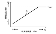
- FIG. 4 is a diagram schematically showing the relationship between the sulfur accumulation amount and the desulfurization temperature.
- FIG. 5 is a diagram schematically showing the relationship between the lean NOx trap catalyst device temperature and the NOx purification rate corresponding to the difference in the sulfur accumulation amount of the lean NOx trap catalyst device.
- the internal combustion engine of the embodiment according to the present invention is configured to include the exhaust gas purification system of the internal combustion engine of the embodiment according to the present invention, and has the same effect as the exhaust gas purification system of the internal combustion engine described later. The effect of this can be achieved.
- an internal combustion engine (hereinafter referred to as an engine) 10 and an exhaust gas purification system 20 for an internal combustion engine according to an embodiment of the present invention will be described with reference to FIG.
- the engine 10 is provided with a fuel injection device 11, an intake valve 12 and an exhaust valve 13 facing a cylinder (cylinder) 10 a, and further, an intake passage 14 communicating with the intake valve 12 and an exhaust valve 13.
- An exhaust passage 15 and an EGR passage 16 are provided.
- the intake passage 14 is provided with an air cleaner 17, a turbocharger (turbo supercharger) 18 compressor 18 b, an intercooler 19 a, and an intake throttle valve 19 b in order from the upstream side.
- a turbine 18a of the turbocharger 18 and an exhaust gas purification device 21 are provided in this order from the side.
- the EGR passage 16 is provided by connecting an intake passage 14 downstream of the compressor 18b and an exhaust passage 15 upstream of the turbine 18a.
- the EGR passage 16 is provided with an EGR cooler 16a and an EGR valve 16b in this order from the upstream side. Is provided.
- EGR gas exhaust gas
- the exhaust gas purification device 21 of the exhaust gas purification system 20 includes an oxidation catalyst device (DOC) 22, a particulate collection device (CSF) 23, a lean NOx trap catalyst device (LNT) 24, and a rear stage in the configuration of FIG.
- a catalyst device such as an oxidation catalyst device (DOC) 25 is provided.
- the arrangement order of the particulate collection device 23 and the lean NOx trap catalyst device 24 is reversed, that is, the oxidation catalyst device 22, the lean NOx trap catalyst device 24, the particulate collection device 23, and the subsequent oxidation catalyst device 25 in this order.
- the exhaust gas purification device 21 may be provided with each catalyst device.
- a fuel injection device 26 for injecting unburned fuel into the exhaust passage 15 is disposed in the exhaust passage 15 upstream of the oxidation catalyst device 22, and NOx regeneration control for the lean NOx trap catalyst device 24, the oxidation catalyst device.
- the unburned fuel is injected into the exhaust passage 15 at the time of exhaust gas temperature rise control such as sulfur purge control for the NO 22 and lean NOx trap catalyst device 24 and PM regeneration control for the particulate collection device 23.
- exhaust gas temperature rise control such as sulfur purge control for the NO 22 and lean NOx trap catalyst device 24 and PM regeneration control for the particulate collection device 23.
- the lean NOx trap catalyst device 24 is heated to the temperature range for releasing and reducing the stored NOx, or fine particles.
- the temperature of the collection device 23 is raised to a temperature range where PM combustion is possible, or the temperature of the oxidation catalyst device 22 and the lean NOx trap catalyst device 24 is raised to a temperature range where desulfurization is possible. Thereby, the exhaust gas purification capacity of each catalyst device 22, 23, 24 is recovered.
- a first temperature sensor 31 for detecting the temperature of the exhaust gas Ga flowing into the oxidation catalyst device 22 is disposed in the exhaust passage 15 upstream (inlet side) of the oxidation catalyst device 22, and a lean NOx trap catalyst.
- a second temperature sensor 32 for detecting the temperature of the exhaust gas Ga flowing into the lean NOx trap catalyst device 24 is disposed in the exhaust passage 15 upstream of the device 24, and the oxidation catalyst device 22 and the particulate collection device 23.
- a third temperature sensor 33 that detects the temperature of the exhaust gas Ga that flows out of the oxidation catalyst device 22 and flows into the particulate collection device 23 is disposed in the exhaust passage 15 therebetween.
- the temperature detected by the second temperature sensor 32 is usually used. However, a temperature sensor (not shown) is provided on the downstream side of the lean NOx trap catalyst device 24 and is detected by this temperature sensor. The temperature may be used, or a temperature that is an average value of the temperature detected by the temperature sensor and the temperature detected by the second temperature sensor 32 may be used.
- a ⁇ sensor 34 or an oxygen concentration sensor (not shown) for measuring the excess air ratio ⁇ or the oxygen concentration of the exhaust gas Ga is arranged on the downstream side of the exhaust gas purification device 21.
- the ⁇ sensor or the oxygen concentration sensor may be disposed on the upstream side of the exhaust gas purification device 21 or may be disposed on the exhaust manifold.
- a NOx concentration sensor 35 for detecting the NOx concentration D of the exhaust gas Ga flowing into the lean NOx trap catalyst device 24 is disposed in the exhaust passage 15 upstream of the lean NOx trap catalyst device 24.
- the NOx concentration sensor 35 is not necessarily arranged.
- control device 40 for controlling the exhaust gas purification system 20 for the internal combustion engine of the present invention is provided.
- the control device 40 is normally configured to be incorporated in an engine control unit (ECU) that controls the operation state of the engine 10 in general, but may be provided independently.
- ECU engine control unit
- the control device 40 for controlling the exhaust gas purification system 20 includes a sulfur storage amount calculating means 41, sulfur desulfurization, as shown in FIG.
- An amount calculation unit 42, a sulfur accumulation amount calculation unit 43, a desulfurization temperature calculation unit 44, a desulfurization control execution unit 45, and the like are provided.
- the sulfur storage amount calculating means 41 is a means for calculating the sulfur storage amount ⁇ So by integrating the sulfur amount So stored and flowing into the lean NOx trap catalyst device 24 during normal operation of the engine 10.
- the normal operation of the engine 10 refers to the operation of the engine 10 when the desulfurization control for recovering the sulfur poisoning of the lean NOx trap catalyst device 24 and the NOx regeneration control for recovering the NOx occlusion capability are not performed (the shutdown is also performed). Including).
- the sulfur desulfurization amount calculation means 42 is a means for calculating the sulfur reduction amount ⁇ Sd by integrating the sulfur amount Sd desorbed from the lean NOx trap catalyst device 24 during the desulfurization control. Further, the sulfur accumulation amount calculating means 43 calculates the sulfur accumulation amount Sa by subtracting the sulfur reduction amount ⁇ Sd calculated by the sulfur desulfurization amount calculating means 42 from the sulfur storage amount ⁇ So calculated from the sulfur storage amount calculating means 41. It is means to do.
- the desulfurization temperature calculation means 44 which is the center of the present invention, is based on the relationship between the sulfur accumulation amount Sa calculated by the sulfur accumulation amount calculation means 43 and the desulfurization temperature Tt that is the target temperature during desulfurization control. Is a means for calculating a desulfurization temperature Tt at the time of desulfurization control based on a database indicating
- the relationship between the sulfur accumulation amount Sa and the desulfurization temperature Tt is set in advance based on experimental results and stored in the control device 40 in the form of a control data map.
- the relationship between the sulfur accumulation amount Sa and the desulfurization temperature Tt is, for example, as shown in FIG. 4. When the sulfur accumulation amount Sa is small, the desulfurization temperature Tt is low, and when the sulfur accumulation amount Sa is large, the desulfurization temperature Tt is high. Become.
- an upper limit value Ttmax (for example, 650 ° C. to 700 ° C.) considering this heat resistance is added to the desulfurization temperature Tt at the time of desulfurization control.
- the desulfurization control execution means 45 is a means for controlling the temperature of the exhaust gas so that the temperature of the exhaust gas Ga becomes the desulfurization temperature Tt calculated by the desulfurization temperature calculation means 44. This desulfurization control is well known. Use the method.
- the control device 40 uses the sulfur accumulation amount accumulated in the lean NOx trap catalyst device 24 as the desulfurization temperature Tt, which is the target temperature when performing the desulfurization control of the lean NOx trap catalyst device 24.
- the setting is made corresponding to Sa.
- a sulfur storage amount calculation step S41 a sulfur desulfurization amount calculation step S42, a sulfur accumulation amount calculation step S43, desulfurization.
- the temperature calculation step S44, the desulfurization control execution step S45, etc. are provided.
- This sulfur storage amount calculation step S41 is a step of calculating the sulfur storage amount ⁇ So by integrating the sulfur amount So that flows into the lean NOx trap catalyst device 24 during normal operation of the engine 10 and is stored, and calculates the sulfur desulfurization amount.
- Step S42 is a step of calculating the sulfur reduction amount ⁇ Sd by integrating the sulfur amount Sd desorbed from the lean NOx trap catalyst device 24 during the desulfurization control.
- the sulfur accumulation amount calculation step S43 calculates the sulfur accumulation amount Sa by subtracting the sulfur reduction amount ⁇ Sd calculated in the sulfur desulfurization amount calculation step S42 from the sulfur storage amount ⁇ So calculated in the sulfur storage amount calculation step S41. It is a step to do.
- the desulfurization temperature calculation step S44 is based on a database showing the relationship between the sulfur accumulation amount Sa calculated from the sulfur accumulation amount calculation step S43 and the desulfurization temperature Tt that is the target temperature at the time of desulfurization control.
- the desulfurization temperature Tt at the time of desulfurization control is calculated, and the desulfurization control execution step S45 raises the exhaust gas so that the temperature of the exhaust gas Ga becomes the desulfurization temperature Tt calculated at the desulfurization temperature calculation step S44.
- This is a control step, and a known method is used as this desulfurization control.
- the exhaust gas purification method S40 for an internal combustion engine accumulates the desulfurization temperature Tt, which is the target temperature when performing the desulfurization control of the lean NOx trap catalyst device 24, in the lean NOx trap catalyst device 24.
- This is a method of setting corresponding to the sulfur accumulation amount Sa.
- the sulfur accumulation amount Sa is calculated at the start of the desulfurization control, and this sulfur accumulation amount Sa.
- the rich control including the exhaust gas temperature increase control is performed for a preset time so that the detection temperature of the exhaust gas becomes the desulfurization temperature Tt, with the desulfurization temperature Tt determined according to the target temperature. Desulfurization treatment.
- the sulfur accumulation amount Sa increases because the desulfurization control is not completed.
- the amount of sulfur decrease due to the desorption of sulfur decreases, and the sulfur accumulation amount Sa increases.
- the next desulfurization temperature Tt is set high, desulfurization is promoted, the amount of sulfur decrease due to the desorption of sulfur increases, and the sulfur accumulation amount Sa decreases.
- the amount of sulfur decrease due to the desorption of sulfur increases, and the sulfur accumulation amount Sa decreases.
- the next desulfurization temperature Tt is set low, the acceleration of desulfurization is weakened and the amount of sulfur decrease due to the desorption of sulfur is reduced, but since the sulfur accumulation amount Sa is originally small, the sulfur accumulation after desulfurization is reduced.
- the amount Sa can be set to a target value. In this desulfurization control, since the desulfurization temperature Tt is low, thermal deterioration in the catalyst of the lean NOx trap catalyst device 24 can be reduced.
- the exhaust gas purification system 20 of the internal combustion engine the internal combustion engine 10 and the exhaust gas purification method S40 of the internal combustion engine, when performing the desulfurization control of the lean NOx trap catalyst device 24, the previous desulfurization control is stopped or interrupted.
- the sulfur accumulation amount Sa of the lean NOx trap catalyst device 24 is calculated in consideration of the degree of desulfurization such as whether or not, and the desulfurization temperature Tt is set according to the calculated sulfur accumulation amount Sa, so that the robustness is excellent.
- the desulfurization control can be performed, the desulfurization process can be reliably performed while the thermal deterioration and the melting loss of the lean NOx trap catalyst device 24 are suppressed, and the NOx purification rate can be maintained.
Abstract
In this exhaust gas purification system 20 for an internal combustion engine, a lean NOx trap catalyst device 24 is provided to an exhaust passage 15 of an engine 10. A control device 40 for controlling the exhaust gas purification system 20 is configured such that a desulfurization temperature Tt, which serves as a target temperature for when performing desulfurization control on the lean NOx trap catalyst device 24, is set so as to correspond to the sulfur storage amount Sa stored in the lean NOx trap catalyst device 24. As a result, an exhaust gas purification system for an internal combustion engine, an internal combustion engine, and an exhaust gas purification method for an internal combustion engine are provided, with which, when desulfurization control is performed on the lean NOx trap catalyst device provided to the exhaust gas purification system for an internal combustion engine, desulfurization treatment is reliably performed while heat deterioration and erosion of the lean NOx trap catalyst device are inhibited, and desulfurization control exhibiting excellent robustness is performed, and thus a high NOx purification rate is maintained.
Description
本発明は、内燃機関の排気ガス浄化システム、内燃機関及び内燃機関の排気ガス浄化方法に関し、より詳細には、リーンNOxトラップ触媒装置の熱劣化、溶損を抑制しつつ、脱硫処理を確実に行うことができる内燃機関の排気ガス浄化システム、内燃機関及び内燃機関の排気ガス浄化方法に関する。
The present invention relates to an exhaust gas purification system for an internal combustion engine, an internal combustion engine, and an exhaust gas purification method for an internal combustion engine. More specifically, the present invention relates to a desulfurization process while suppressing thermal deterioration and erosion of a lean NOx trap catalyst device. The present invention relates to an exhaust gas purification system for an internal combustion engine, an internal combustion engine, and an exhaust gas purification method for the internal combustion engine.
一般に、ディーゼルエンジン等の内燃機関の排気ガスに含まれる炭化水素(HC)、一酸化炭素(CO)、窒素酸化物(NOx)及び微粒子状物質(PM)等の浄化対象成分を浄化するために、酸化触媒装置(DOC)、微粒子捕集装置(CSF、SCRF等)、選択還元型触媒装置(SCR)、リーンNOxトラップ触媒装置(LNT)等の各触媒装置を有する排気ガス浄化装置を備えた排気ガス浄化システムが使用されている。
In general, in order to purify components to be purified such as hydrocarbons (HC), carbon monoxide (CO), nitrogen oxides (NOx), and particulate matter (PM) contained in exhaust gas of an internal combustion engine such as a diesel engine. , An exhaust gas purification device having each catalyst device such as an oxidation catalyst device (DOC), a particulate collection device (CSF, SCRF, etc.), a selective catalytic reduction device (SCR), a lean NOx trap catalyst device (LNT), etc. An exhaust gas purification system is used.
排気通路にリーンNOxトラップ触媒装置(LNT)を備えて、排気ガスに含まれる窒素酸化物(NOx)を浄化処理する排気ガス浄化システムでは、リーンバーンやディーゼルエンジンの様に排気ガス中に酸素過多のリーン状態の時に、一時的にNOxをリーンNOxトラップ触媒装置に吸蔵し、NOx吸蔵量が多くなって吸蔵しきれずに下流側にスリップする量が増えてきたら、定期的に排気ガスをリッチ空燃比にするリッチ制御をして、リーンNOxトラップ触媒装置に吸蔵したNOxを放出させて還元する。この吸蔵及び還元の動作を繰り返して、リーンNOxトラップ触媒装置によるNOx浄化率を維持する機構となっている。
In an exhaust gas purification system equipped with a lean NOx trap catalyst device (LNT) in the exhaust passage to purify nitrogen oxides (NOx) contained in the exhaust gas, the exhaust gas contains excessive oxygen as in lean burn and diesel engines. If the NOx is temporarily occluded in the lean NOx trap catalyst device during the lean state of the engine and the amount of NOx occluded increases and the amount of slippage downstream increases without being occluded, the exhaust gas will The rich control to make the fuel ratio is performed, and the NOx occluded in the lean NOx trap catalyst device is released and reduced. This occlusion and reduction operation is repeated to maintain a NOx purification rate by the lean NOx trap catalyst device.
このリーンNOxトラップ触媒装置は、燃料やエンジンオイルの一成分であり排気ガスに含まれる硫黄(S)も、NOxの吸蔵と同様に吸蔵してしまうことによる、NOxの吸蔵容量の減少という硫黄被毒の問題があることが知られている。そのため、定期的に、排気ガスを昇温して600℃程度まで高温化し、かつ、リッチ雰囲気に移行して、高温のリッチ雰囲気でリーンNOxトラップ触媒装置に吸蔵した硫黄を脱離させる脱硫制御(Sパージ制御)を行っている。
This lean NOx trap catalyst device is a component of fuel and engine oil, and sulfur (S) contained in exhaust gas is also occluded in the same manner as NOx occlusion, thereby reducing the NOx occlusion capacity. It is known that there is a poison problem. Therefore, desulfurization control (desulfurization control in which the exhaust gas is periodically heated to about 600 ° C. and shifted to a rich atmosphere to desorb sulfur stored in the lean NOx trap catalyst device in a high temperature rich atmosphere ( S purge control) is performed.
リーンNOxトラップ触媒装置の脱硫制御は、排気ガスが高温かつ空気過剰率(λ)が低い程、その脱硫効率は上がるが、リーンNOxトラップ触媒装置の熱劣化、溶損が進行する虞がある。よって、通常は、熱劣化、溶損の抑制と、硫黄被毒回復のバランスを取り、排気ガスに含まれるNOxの浄化率が最も維持できる脱硫処理条件で脱硫制御を行う。
In the desulfurization control of the lean NOx trap catalyst device, the higher the exhaust gas is, and the lower the excess air ratio (λ), the higher the desulfurization efficiency, but there is a risk that the lean NOx trap catalyst device will be thermally deteriorated and melted. Therefore, normally, desulfurization control is performed under a desulfurization process condition that balances suppression of thermal deterioration and erosion loss and recovery from sulfur poisoning, and can most maintain the purification rate of NOx contained in the exhaust gas.
これに関連して、例えば、日本出願の特開2010-144557号公報に記載されているように、内燃機関の排気ガス浄化システムにおいて、NOx吸蔵還元型触媒を通過した排気ガスのDPF又は触媒付きDPFへの流量を抑制して、PM再生温度を適温に維持しながら、NOx吸蔵還元型触媒の脱硫制御とDPF又は触媒付きDPFのPM再生処理とを同時に並行して行う排気ガス浄化システム及び排気ガス浄化方法が提案されている。
In relation to this, as described in Japanese Patent Application Laid-Open No. 2010-144557, for example, in an exhaust gas purification system for an internal combustion engine, DPF of exhaust gas that has passed through a NOx occlusion reduction type catalyst or with a catalyst is provided. Exhaust gas purification system and exhaust that simultaneously perform desulfurization control of NOx occlusion reduction catalyst and PM regeneration processing of DPF or DPF with catalyst while suppressing flow rate to DPF and maintaining PM regeneration temperature at appropriate temperature Gas purification methods have been proposed.
しかしながら、リーンNOxトラップ触媒装置の脱硫制御はある程度の時間が必要なために、脱硫制御の途中で、エンジン運転状態が脱硫制御可能な運転領域を外れたり、エンジンが停止されたりすると、脱硫制御が中止または中断される。通常、この脱硫制御は、排気ガスの高温化が必要なため、微粒子捕集装置(CSF、SCRF等)のPM再生制御と同時に行われることが多いので、脱硫制御を中止または中断した場合は、次回のPM再生制御まで脱硫制御が延期されることとなる。
However, since a certain amount of time is required for the desulfurization control of the lean NOx trap catalyst device, the desulfurization control is performed when the engine operating state is out of the operation range where desulfurization control is possible or the engine is stopped during the desulfurization control. Canceled or interrupted. Usually, this desulfurization control requires a high temperature of the exhaust gas, and is therefore often performed simultaneously with PM regeneration control of a particulate collection device (CSF, SCRF, etc.), so when desulfurization control is stopped or interrupted, The desulfurization control will be postponed until the next PM regeneration control.
この場合、硫黄蓄積量は、脱硫制御が完了した場合よりも多くなるので、次回の脱硫制御を行っても、蓄積した硫黄を十分に脱硫することができず、残留した硫黄量分だけNOx吸蔵容量が少ない状態でNOx浄化を行うため、NOx浄化率が低下する虞がある。
In this case, the amount of accumulated sulfur is greater than when the desulfurization control is completed. Therefore, even if the next desulfurization control is performed, the accumulated sulfur cannot be sufficiently desulfurized, and the remaining amount of sulfur is stored as NOx. Since NOx purification is performed with a small capacity, the NOx purification rate may be reduced.
例えば、最も浄化率を高い状態で維持できるXmgごとにTx℃の脱硫制御を行っている場合で、脱硫制御に当初から失敗した場合は、次回の脱硫制御までに硫黄がYmg(>Xmg)まで蓄積してしまい、次回の脱硫制御が完了したとしても、完全に脱硫しきれずに、硫黄が残り、NOx浄化率が低下する。
For example, when desulfurization control at Tx ° C. is performed for each Xmg at which the purification rate can be maintained at the highest level, if desulfurization control has failed from the beginning, sulfur will reach Ymg (> Xmg) until the next desulfurization control. Even if it accumulates and the next desulfurization control is completed, it cannot completely desulfurize, sulfur remains, and the NOx purification rate decreases.
つまり、図5に、硫黄蓄積量(硫黄残留量)がXmg(S=S1)のときと、(Y=2×X)mg(S=S2)の場合のLNT触媒温度とNOx浄化率の関係を模式的に示すように、S=S1に比べて硫黄蓄積量が多いS=S2では、LNT触媒温度が低い範囲ではNOxが著しく低下する。一方、LNT触媒温度が高い範囲ではNOxが逆転するが、LNT触媒温度が高いため、触媒の熱劣化が進むことになる。
That is, FIG. 5 shows the relationship between the LNT catalyst temperature and the NOx purification rate when the sulfur accumulation amount (sulfur residual amount) is Xmg (S = S1) and (Y = 2 × X) mg (S = S2). In S = S2, where the amount of accumulated sulfur is larger than S = S1, NOx significantly decreases in a range where the LNT catalyst temperature is low. On the other hand, NOx reverses in the range where the LNT catalyst temperature is high, but since the LNT catalyst temperature is high, the thermal deterioration of the catalyst proceeds.
本発明者は、内燃機関の排気ガスシステムに備えたリーンNOxトラップ触媒装置の脱硫制御を行うときに、脱硫制御における脱硫温度が高い程、脱硫量が多いので、脱硫制御毎の硫黄蓄積量を算出することで前回の脱硫制御が中止または中断されたか否かを反映させて、この硫黄蓄積量に対応して脱硫温度を設定することで、脱硫制御が中止または中断されて硫黄蓄積量が多くなったときでも、確実に脱硫処理できて硫黄被毒によるNOx浄化率の低下を抑制することができ、しかも、硫黄蓄積量が少ないときには脱硫温度を低くできるので触媒の熱劣化も抑制できるとの知見を得た。
When performing desulfurization control of a lean NOx trap catalyst device provided in an exhaust gas system of an internal combustion engine, the inventor increases the desulfurization amount as the desulfurization temperature is higher in the desulfurization control. By calculating whether or not the previous desulfurization control was stopped or interrupted, and setting the desulfurization temperature corresponding to this sulfur accumulation amount, the desulfurization control was interrupted or interrupted and the sulfur accumulation amount increased. Even when it becomes low, it can be reliably desulfurized, and the NOx purification rate reduction due to sulfur poisoning can be suppressed, and when the amount of accumulated sulfur is small, the desulfurization temperature can be lowered, so that thermal deterioration of the catalyst can also be suppressed. Obtained knowledge.
本発明は、上記のことを鑑みてなされたものであり、その目的は、内燃機関の排気ガスシステムに備えたリーンNOxトラップ触媒装置の脱硫制御を行うときに、リーンNOxトラップ触媒装置の熱劣化、溶損を抑制しつつ、脱硫処理を確実に行うことができる、ロバスト性に優れた脱硫制御を行うことができ、これにより、高いNOx浄化率を維持することができる、内燃機関の排気ガス浄化システム、内燃機関及び内燃機関の排気ガス浄化方法を提供することにある。
The present invention has been made in view of the above, and an object of the present invention is to perform thermal degradation of a lean NOx trap catalyst device when performing desulfurization control of a lean NOx trap catalyst device provided in an exhaust gas system of an internal combustion engine. The exhaust gas of the internal combustion engine, which can perform desulfurization processing reliably while suppressing melting loss, can perform desulfurization control with excellent robustness, and can thereby maintain a high NOx purification rate An object of the present invention is to provide a purification system, an internal combustion engine, and an exhaust gas purification method for the internal combustion engine.
上記の目的を達成するための本発明の内燃機関の排気ガス浄化システムは、内燃機関の排気通路にリーンNOxトラップ触媒装置を備えた内燃機関の排気ガス浄化システムにおいて、該排気ガス浄化システムを制御する制御装置が、前記リーンNOxトラップ触媒装置の脱硫制御を行うときの目標温度となる脱硫温度を、前記リーンNOxトラップ触媒装置に蓄積されている硫黄蓄積量に対応させて設定するように構成される。
In order to achieve the above object, an exhaust gas purification system for an internal combustion engine of the present invention controls the exhaust gas purification system in an exhaust gas purification system for an internal combustion engine provided with a lean NOx trap catalyst device in an exhaust passage of the internal combustion engine. And a control device configured to set a desulfurization temperature, which is a target temperature when performing the desulfurization control of the lean NOx trap catalyst device, in accordance with a sulfur accumulation amount accumulated in the lean NOx trap catalyst device. The
この構成によれば、リーンNOxトラップ触媒装置の脱硫制御を行うときに、内燃機関の停止等に起因して前回の脱硫制御が中止されたか否かを考慮してリーンNOxトラップ触媒装置の硫黄蓄積量を算出し、この算出した硫黄蓄積量に応じて、脱硫温度を設定することで、ロバスト性に優れた脱硫制御を行うことができ、リーンNOxトラップ触媒装置の熱劣化、溶損を抑制しつつ、脱硫処理を確実に行うことができ、NOx浄化率を維持することができる。
According to this configuration, when the desulfurization control of the lean NOx trap catalyst device is performed, the sulfur accumulation of the lean NOx trap catalyst device is considered in consideration of whether or not the previous desulfurization control was stopped due to the stop of the internal combustion engine or the like. By calculating the amount and setting the desulfurization temperature according to the calculated sulfur accumulation amount, it is possible to perform desulfurization control with excellent robustness, and suppress thermal deterioration and erosion of the lean NOx trap catalyst device. However, the desulfurization process can be performed reliably, and the NOx purification rate can be maintained.
また、上記の内燃機関の排気ガス浄化システムにおいて、前記制御装置が、前記内燃機関の通常運転時に前記リーンNOxトラップ触媒装置に流入して吸蔵される硫黄量を積算して硫黄吸蔵量を算出する硫黄吸蔵量算出手段と、脱硫制御時に前記リーンNOxトラップ触媒装置より脱離される硫黄量を積算して硫黄減少量を算出する硫黄脱硫量算出手段と、前記硫黄吸蔵量算出手段で算出された硫黄吸蔵量から前記硫黄脱硫量算出手段で算出された硫黄減少量を引き算して硫黄蓄積量を算出する硫黄蓄積量算出手段と、該硫黄蓄積量算出手段により算出された硫黄蓄積量から、硫黄蓄積量と脱硫制御時の目標温度である脱硫温度との関係を示すデータベースを基に、脱硫制御時の脱硫温度を算出する脱硫温度算出手段と、排気ガスの温度が前記脱硫温度算出手段で算出された脱硫温度になるように、排気ガスを昇温制御する脱硫制御実施手段とを備えて構成されると、リーンNOxトラップ触媒装置の硫黄蓄積量を算出しながら、脱硫温度の設定を行うことができる。
Further, in the exhaust gas purification system for an internal combustion engine, the control device calculates the sulfur storage amount by integrating the amount of sulfur stored in the lean NOx trap catalyst device during normal operation of the internal combustion engine. Sulfur occlusion amount calculation means, sulfur desulfurization amount calculation means for calculating a sulfur reduction amount by integrating the amount of sulfur desorbed from the lean NOx trap catalyst device during desulfurization control, and sulfur calculated by the sulfur storage amount calculation means A sulfur accumulation amount calculating means for calculating a sulfur accumulation amount by subtracting a sulfur reduction amount calculated by the sulfur desulfurization amount calculating means from a storage amount, and a sulfur accumulation amount from the sulfur accumulation amount calculated by the sulfur accumulation amount calculating means. The desulfurization temperature calculation means for calculating the desulfurization temperature at the time of desulfurization control based on a database showing the relationship between the amount and the target temperature at the time of desulfurization control, and the exhaust gas temperature If the desulfurization temperature calculating means is configured to include the desulfurization control execution means for controlling the temperature of the exhaust gas so that the desulfurization temperature is calculated, the sulfur accumulation amount of the lean NOx trap catalyst device is calculated. The desulfurization temperature can be set.
ここで、上記の内燃機関の通常運転とは、リーンNOxトラップ触媒装置の硫黄被毒を回復するための脱硫制御とNOx吸蔵能力を回復するためのNOx再生制御を行わないときのエンジンの運転(停止も含む)のことをいう。
Here, the normal operation of the internal combustion engine refers to the operation of the engine when the desulfurization control for recovering the sulfur poisoning of the lean NOx trap catalyst device and the NOx regeneration control for recovering the NOx storage capacity are not performed ( (Including stoppage).
また、上記の目的を達成するための本発明の内燃機関は、上記の内燃機関の排気ガス浄化システムを備えて構成され、上記の内燃機関の排気ガス浄化システムと同様の作用効果を奏することができる。
In order to achieve the above object, an internal combustion engine of the present invention is configured to include the exhaust gas purification system of the internal combustion engine, and has the same effects as the exhaust gas purification system of the internal combustion engine. it can.
また、上記の目的を達成するための本発明の内燃機関の排気ガス浄化方法は、内燃機関の排気通路にリーンNOxトラップ触媒装置を備えた内燃機関の排気ガス浄化方法において、前記リーンNOxトラップ触媒装置の脱硫制御を行うときの目標温度となる脱硫温度を、前記リーンNOxトラップ触媒装置に蓄積されている硫黄蓄積量に対応させて設定することを特徴とする方法である。
In addition, the exhaust gas purification method for an internal combustion engine of the present invention for achieving the above object is the exhaust gas purification method for an internal combustion engine provided with a lean NOx trap catalyst device in an exhaust passage of the internal combustion engine. In this method, a desulfurization temperature, which is a target temperature when performing desulfurization control of the apparatus, is set in accordance with a sulfur accumulation amount accumulated in the lean NOx trap catalyst apparatus.
また、上記の内燃機関の排気ガス浄化方法において、前記内燃機関の通常運転時に前記リーンNOxトラップ触媒装置に流入して吸蔵される硫黄量を積算して硫黄吸蔵量を算出する硫黄吸蔵量算出ステップと、脱硫制御時に前記リーンNOxトラップ触媒装置より脱離される硫黄量を積算して硫黄減少量を算出する硫黄脱硫量算出ステップと、前記硫黄吸蔵量算出ステップで算出された硫黄吸蔵量から前記硫黄脱硫量算出ステップで算出された硫黄減少量を引き算して硫黄蓄積量を算出する硫黄蓄積量算出ステップと、該硫黄蓄積量算出ステップにより算出された硫黄蓄積量から、硫黄蓄積量と脱硫制御時の目標温度である脱硫温度との関係を示すデータベースを基に、脱硫制御時の脱硫温度を算出する脱硫温度算出ステップと、排気ガスの温度が前記脱硫温度算出ステップで算出された脱硫温度になるように、排気ガスを昇温制御する脱硫制御実施ステップとを備えて構成される。
Further, in the above exhaust gas purification method for an internal combustion engine, a sulfur storage amount calculation step of calculating a sulfur storage amount by integrating the amount of sulfur stored and stored in the lean NOx trap catalyst device during normal operation of the internal combustion engine. A sulfur desulfurization amount calculating step of calculating a sulfur reduction amount by integrating the amount of sulfur desorbed from the lean NOx trap catalyst device during desulfurization control, and the sulfur storage amount calculated in the sulfur storage amount calculating step. The sulfur accumulation amount calculation step for calculating the sulfur accumulation amount by subtracting the sulfur reduction amount calculated in the desulfurization amount calculation step, and the sulfur accumulation amount and the desulfurization control time from the sulfur accumulation amount calculated by the sulfur accumulation amount calculation step. A desulfurization temperature calculation step for calculating a desulfurization temperature at the time of desulfurization control based on a database indicating a relationship with a desulfurization temperature that is a target temperature of the exhaust gas, and an exhaust gas Temperature so is the desulfurization temperature calculated in the desulfurization temperature calculating step constituted by a desulfurization control execution step of raising the temperature control of the exhaust gas.
これらの方法によれば、上記の内燃機関の排気ガス浄化システムと同様の作用効果を奏することができる。
According to these methods, the same effects as the exhaust gas purification system of the internal combustion engine can be obtained.
本発明の内燃機関の排気ガス浄化システム、内燃機関及び内燃機関の排気ガス浄化方法によれば、リーンNOxトラップ触媒装置の脱硫制御を行うときに、内燃機関の停止等に起因して前回の脱硫制御が中止されたか否かを考慮してリーンNOxトラップ触媒装置の硫黄蓄積量を算出し、この算出した硫黄蓄積量に応じて脱硫温度を設定するので、リーンNOxトラップ触媒装置の熱劣化、溶損を抑制しつつ、脱硫処理を確実に行うことができる、ロバスト性に優れた脱硫制御を行うことができ、これにより、高いNOx浄化率を維持することができる。
According to the exhaust gas purification system of an internal combustion engine, the internal combustion engine, and the exhaust gas purification method of the internal combustion engine of the present invention, when performing desulfurization control of the lean NOx trap catalyst device, the previous desulfurization due to the stop of the internal combustion engine or the like. The sulfur accumulation amount of the lean NOx trap catalyst device is calculated in consideration of whether or not the control is stopped, and the desulfurization temperature is set according to the calculated sulfur accumulation amount. The desulfurization control with excellent robustness capable of reliably performing the desulfurization treatment while suppressing the loss can be performed, and thereby a high NOx purification rate can be maintained.
以下、本発明に係る実施の形態の内燃機関の排気ガス浄化システム、内燃機関及び内燃機関の排気ガス浄化方法について図面を参照しながら説明する。なお、本発明に係る実施の形態の内燃機関は、本発明に係る実施の形態の内燃機関の排気ガス浄化システムを備えて構成され、後述する内燃機関の排気ガス浄化システムが奏する作用効果と同様の作用効果を奏することができる。
Hereinafter, an exhaust gas purification system for an internal combustion engine, an internal combustion engine, and an exhaust gas purification method for the internal combustion engine according to embodiments of the present invention will be described with reference to the drawings. The internal combustion engine of the embodiment according to the present invention is configured to include the exhaust gas purification system of the internal combustion engine of the embodiment according to the present invention, and has the same effect as the exhaust gas purification system of the internal combustion engine described later. The effect of this can be achieved.
最初に、図1を参照しながら、本発明に係る実施の形態の内燃機関(以下エンジン)10と内燃機関の排気ガス浄化システム20について説明する。このエンジン10には、気筒(シリンダ)10aに面して燃料噴射装置11と吸気弁12と排気弁13が設けられ、更に、吸気弁12に連通する吸気通路14と、排気弁13に連通する排気通路15と、EGR通路16が設けられている。
First, an internal combustion engine (hereinafter referred to as an engine) 10 and an exhaust gas purification system 20 for an internal combustion engine according to an embodiment of the present invention will be described with reference to FIG. The engine 10 is provided with a fuel injection device 11, an intake valve 12 and an exhaust valve 13 facing a cylinder (cylinder) 10 a, and further, an intake passage 14 communicating with the intake valve 12 and an exhaust valve 13. An exhaust passage 15 and an EGR passage 16 are provided.
この吸気通路14には、上流側より順に、エアクリーナ17、ターボチャージャ(ターボ式過給器)18のコンプレッサ18b、インタークーラ19a、インテークスロットルバルブ19bが設けられ、また、排気通路15には、上流側より順に、ターボチャージャ18のタービン18a、排気ガス浄化装置21が設けられている。また、EGR通路16は、コンプレッサ18bより下流の吸気通路14とタービン18aより上流の排気通路15を接続して設けられ、このEGR通路16には、上流側より順に、EGRクーラ16a、EGRバルブ16bが設けられている。
The intake passage 14 is provided with an air cleaner 17, a turbocharger (turbo supercharger) 18 compressor 18 b, an intercooler 19 a, and an intake throttle valve 19 b in order from the upstream side. A turbine 18a of the turbocharger 18 and an exhaust gas purification device 21 are provided in this order from the side. The EGR passage 16 is provided by connecting an intake passage 14 downstream of the compressor 18b and an exhaust passage 15 upstream of the turbine 18a. The EGR passage 16 is provided with an EGR cooler 16a and an EGR valve 16b in this order from the upstream side. Is provided.
そして、大気から導入される新気Aは、必要に応じて、EGR通路16から吸気通路14に流入する排気ガス(EGRガス)Geを伴って、吸気弁12経由で気筒(シリンダ)10aに送られる。また、気筒10aで発生した排気ガスGは、排気弁13経由で排気通路15に流出し、その一部はEGR通路16にEGRガスGeとして流れ、残りの排気ガスGa(=G-Ge)は、タービン18aを経由して、排気ガス浄化装置21に流入して、浄化された後、浄化された排気ガスGcとしてマフラー(図示しない)、テールパイプ(図示しない)を経由して大気中へ放出される。
The fresh air A introduced from the atmosphere is sent to the cylinder (cylinder) 10a via the intake valve 12 with the exhaust gas (EGR gas) Ge flowing into the intake passage 14 from the EGR passage 16 as necessary. It is done. Further, the exhaust gas G generated in the cylinder 10a flows into the exhaust passage 15 via the exhaust valve 13, a part of which flows as the EGR gas Ge into the EGR passage 16, and the remaining exhaust gas Ga (= G-Ge) is generated. Then, after flowing into the exhaust gas purification device 21 via the turbine 18a and being purified, it is discharged into the atmosphere as a purified exhaust gas Gc via a muffler (not shown) and a tail pipe (not shown). Is done.
また、排気ガス浄化システム20の排気ガス浄化装置21は、この図1の構成では、酸化触媒装置(DOC)22、微粒子捕集装置(CSF)23、リーンNOxトラップ触媒装置(LNT)24及び後段酸化触媒装置(DOC)25等の触媒装置を備えて構成される。なお、微粒子捕集装置23とリーンNOxトラップ触媒装置24の配設順序を逆にして、すなわち、酸化触媒装置22、リーンNOxトラップ触媒装置24、微粒子捕集装置23、後段酸化触媒装置25の順に、各触媒装置を排気ガス浄化装置21に備える場合もある。
In addition, the exhaust gas purification device 21 of the exhaust gas purification system 20 includes an oxidation catalyst device (DOC) 22, a particulate collection device (CSF) 23, a lean NOx trap catalyst device (LNT) 24, and a rear stage in the configuration of FIG. A catalyst device such as an oxidation catalyst device (DOC) 25 is provided. The arrangement order of the particulate collection device 23 and the lean NOx trap catalyst device 24 is reversed, that is, the oxidation catalyst device 22, the lean NOx trap catalyst device 24, the particulate collection device 23, and the subsequent oxidation catalyst device 25 in this order. The exhaust gas purification device 21 may be provided with each catalyst device.
また、酸化触媒装置22の上流側の排気通路15には、未燃燃料を排気通路15内に噴射する燃料噴射装置26が配設され、リーンNOxトラップ触媒装置24に対するNOx再生制御、酸化触媒装置22とリーンNOxトラップ触媒装置24に対する硫黄パージ制御、微粒子捕集装置23に対するPM再生制御等の排気ガス昇温制御の際に、排気通路15内に未燃燃料を噴射する。この噴射により、未燃燃料である炭化水素を酸化触媒装置22等で酸化して、この酸化熱により排気ガスGaを昇温する。この排気ガスGaの昇温や各触媒装置22、23、24での炭化水素の燃焼による昇温により、リーンNOxトラップ触媒装置24を吸蔵NOxの放出及び還元の温度域まで昇温させたり、微粒子捕集装置23をPM燃焼可能な温度域まで昇温させたり、あるいは、酸化触媒装置22とリーンNOxトラップ触媒装置24を脱硫可能な温度域まで昇温させたりする。これにより、各触媒装置22、23、24の排気ガス浄化能力を回復する。
Further, a fuel injection device 26 for injecting unburned fuel into the exhaust passage 15 is disposed in the exhaust passage 15 upstream of the oxidation catalyst device 22, and NOx regeneration control for the lean NOx trap catalyst device 24, the oxidation catalyst device. The unburned fuel is injected into the exhaust passage 15 at the time of exhaust gas temperature rise control such as sulfur purge control for the NO 22 and lean NOx trap catalyst device 24 and PM regeneration control for the particulate collection device 23. By this injection, hydrocarbons that are unburned fuel are oxidized by the oxidation catalyst device 22 and the like, and the temperature of the exhaust gas Ga is raised by this oxidation heat. By raising the temperature of the exhaust gas Ga and raising the temperature by combustion of hydrocarbons in each of the catalyst devices 22, 23, 24, the lean NOx trap catalyst device 24 is heated to the temperature range for releasing and reducing the stored NOx, or fine particles. The temperature of the collection device 23 is raised to a temperature range where PM combustion is possible, or the temperature of the oxidation catalyst device 22 and the lean NOx trap catalyst device 24 is raised to a temperature range where desulfurization is possible. Thereby, the exhaust gas purification capacity of each catalyst device 22, 23, 24 is recovered.
また、酸化触媒装置22の上流側(入口側)の排気通路15には、酸化触媒装置22に流入する排気ガスGaの温度を検出する第1温度センサ31が配置され、また、リーンNOxトラップ触媒装置24の上流側の排気通路15には、リーンNOxトラップ触媒装置24に流入する排気ガスGaの温度を検出する第2温度センサ32が配置され、また、酸化触媒装置22と微粒子捕集装置23の間の排気通路15には、酸化触媒装置22から流出して微粒子捕集装置23に流入する排気ガスGaの温度を検出する第3温度センサ33が配置される。
A first temperature sensor 31 for detecting the temperature of the exhaust gas Ga flowing into the oxidation catalyst device 22 is disposed in the exhaust passage 15 upstream (inlet side) of the oxidation catalyst device 22, and a lean NOx trap catalyst. A second temperature sensor 32 for detecting the temperature of the exhaust gas Ga flowing into the lean NOx trap catalyst device 24 is disposed in the exhaust passage 15 upstream of the device 24, and the oxidation catalyst device 22 and the particulate collection device 23. A third temperature sensor 33 that detects the temperature of the exhaust gas Ga that flows out of the oxidation catalyst device 22 and flows into the particulate collection device 23 is disposed in the exhaust passage 15 therebetween.
排気ガスGaを昇温制御して、リーンNOxトラップ触媒装置24の脱硫制御を行うときに、この排気ガスGaの昇温制御で制御目標の脱硫温度にするように制御される制御対象となる検出温度としては、第2温度センサ32で検出される温度を用いることが通常であるが、リーンNOxトラップ触媒装置24の下流側に温度センサ(図示しない)を設けて、この温度センサで検出される温度を用いてもよいし、あるいは、この温度センサで検出される温度と第2温度センサ32で検出される温度の平均値となる温度を用いてもよい。
When exhaust gas Ga is heated and controlled to perform desulfurization control of the lean NOx trap catalyst device 24, detection to be controlled is controlled so that the exhaust gas Ga is heated to the control target desulfurization temperature. As the temperature, the temperature detected by the second temperature sensor 32 is usually used. However, a temperature sensor (not shown) is provided on the downstream side of the lean NOx trap catalyst device 24 and is detected by this temperature sensor. The temperature may be used, or a temperature that is an average value of the temperature detected by the temperature sensor and the temperature detected by the second temperature sensor 32 may be used.
さらに、排気ガスGaの空気過剰率λ若しくは酸素濃度を計測するλセンサ34若しくは酸素濃度センサ(図示しない)が排気ガス浄化装置21の下流側に配置される。このλセンサ若しくは酸素濃度センサは、排気ガス浄化装置21の上流側に配置しても、また、排気マニホールドに配置してもよい。
Further, a λ sensor 34 or an oxygen concentration sensor (not shown) for measuring the excess air ratio λ or the oxygen concentration of the exhaust gas Ga is arranged on the downstream side of the exhaust gas purification device 21. The λ sensor or the oxygen concentration sensor may be disposed on the upstream side of the exhaust gas purification device 21 or may be disposed on the exhaust manifold.
また、リーンNOxトラップ触媒装置24の上流側の排気通路15には、リーンNOxトラップ触媒装置24に流入する排気ガスGaのNOx濃度Dを検出するNOx濃度センサ35が配置される。なお、何等かの従来技術の方法で、リーンNOxトラップ触媒装置24に流入する排気ガスGaのNOx濃度Dを推定することができる場合には、このNOx濃度センサ35を必ずしも配置する必要はない。
Further, a NOx concentration sensor 35 for detecting the NOx concentration D of the exhaust gas Ga flowing into the lean NOx trap catalyst device 24 is disposed in the exhaust passage 15 upstream of the lean NOx trap catalyst device 24. When the NOx concentration D of the exhaust gas Ga flowing into the lean NOx trap catalyst device 24 can be estimated by any conventional method, the NOx concentration sensor 35 is not necessarily arranged.
また、本発明の内燃機関の排気ガス浄化システム20を制御する制御装置40を設ける。この制御装置40は、通常は、エンジン10全般の運転状態を制御するエンジンコントロールユニット(ECU)に組み込んで構成するが、独立して設けてもよい。
Further, a control device 40 for controlling the exhaust gas purification system 20 for the internal combustion engine of the present invention is provided. The control device 40 is normally configured to be incorporated in an engine control unit (ECU) that controls the operation state of the engine 10 in general, but may be provided independently.
そして、本発明に係る実施の形態の内燃機関の排気ガス浄化システム20では、この排気ガス浄化システム20を制御する制御装置40は、図2に示すように、硫黄吸蔵量算出手段41、硫黄脱硫量算出手段42、硫黄蓄積量算出手段43、脱硫温度算出手段44、脱硫制御実施手段45等を備えて構成される。
In the exhaust gas purification system 20 for an internal combustion engine according to the embodiment of the present invention, the control device 40 for controlling the exhaust gas purification system 20 includes a sulfur storage amount calculating means 41, sulfur desulfurization, as shown in FIG. An amount calculation unit 42, a sulfur accumulation amount calculation unit 43, a desulfurization temperature calculation unit 44, a desulfurization control execution unit 45, and the like are provided.
この硫黄吸蔵量算出手段41は、エンジン10の通常運転時にリーンNOxトラップ触媒装置24に流入して吸蔵される硫黄量Soを積算して硫黄吸蔵量ΣSoを算出する手段である。このエンジン10の通常運転とは、リーンNOxトラップ触媒装置24の硫黄被毒を回復するための脱硫制御とNOx吸蔵能力を回復するためのNOx再生制御を行わないときのエンジン10の運転(停止も含む)のことをいう。
The sulfur storage amount calculating means 41 is a means for calculating the sulfur storage amount ΣSo by integrating the sulfur amount So stored and flowing into the lean NOx trap catalyst device 24 during normal operation of the engine 10. The normal operation of the engine 10 refers to the operation of the engine 10 when the desulfurization control for recovering the sulfur poisoning of the lean NOx trap catalyst device 24 and the NOx regeneration control for recovering the NOx occlusion capability are not performed (the shutdown is also performed). Including).
また、硫黄脱硫量算出手段42は、脱硫制御時にリーンNOxトラップ触媒装置24より脱離される硫黄量Sdを積算して硫黄減少量ΣSdを算出する手段である。また、硫黄蓄積量算出手段43は、硫黄吸蔵量算出手段41から算出された硫黄吸蔵量ΣSoから、硫黄脱硫量算出手段42で算出された硫黄減少量ΣSdを引き算して硫黄蓄積量Saを算出する手段である。
The sulfur desulfurization amount calculation means 42 is a means for calculating the sulfur reduction amount ΣSd by integrating the sulfur amount Sd desorbed from the lean NOx trap catalyst device 24 during the desulfurization control. Further, the sulfur accumulation amount calculating means 43 calculates the sulfur accumulation amount Sa by subtracting the sulfur reduction amount ΣSd calculated by the sulfur desulfurization amount calculating means 42 from the sulfur storage amount ΣSo calculated from the sulfur storage amount calculating means 41. It is means to do.
そして、本発明の中心となる脱硫温度算出手段44は、硫黄蓄積量算出手段43により算出された硫黄蓄積量Saから、硫黄蓄積量Saと脱硫制御時の目標温度である脱硫温度Ttとの関係を示すデータベースを基に、脱硫制御時の脱硫温度Ttを算出する手段である。
The desulfurization temperature calculation means 44, which is the center of the present invention, is based on the relationship between the sulfur accumulation amount Sa calculated by the sulfur accumulation amount calculation means 43 and the desulfurization temperature Tt that is the target temperature during desulfurization control. Is a means for calculating a desulfurization temperature Tt at the time of desulfurization control based on a database indicating
この硫黄蓄積量Saと脱硫温度Ttの関係は、予め実験結果等に基づいて設定され、制御用のデータマップのような形で制御装置40に記憶される。硫黄蓄積量Saと脱硫温度Ttの関係は、例えば、図4に示すようなもので、硫黄蓄積量Saが少ないときには、脱硫温度Ttは低く、硫黄蓄積量Saが多いときには、脱硫温度Ttは高くなる。
The relationship between the sulfur accumulation amount Sa and the desulfurization temperature Tt is set in advance based on experimental results and stored in the control device 40 in the form of a control data map. The relationship between the sulfur accumulation amount Sa and the desulfurization temperature Tt is, for example, as shown in FIG. 4. When the sulfur accumulation amount Sa is small, the desulfurization temperature Tt is low, and when the sulfur accumulation amount Sa is large, the desulfurization temperature Tt is high. Become.
なお、リーンNOxトラップ触媒装置24の耐熱性の面から昇温の上限があるので、脱硫制御時の脱硫温度Ttに、この耐熱性を考慮した上限値Ttmax(例えば、650℃~700℃)を設ける。
Since there is an upper limit of temperature rise from the viewpoint of heat resistance of the lean NOx trap catalyst device 24, an upper limit value Ttmax (for example, 650 ° C. to 700 ° C.) considering this heat resistance is added to the desulfurization temperature Tt at the time of desulfurization control. Provide.
そして、脱硫制御実施手段45は、排気ガスGaの温度が脱硫温度算出手段44で算出された脱硫温度Ttになるように、排気ガスを昇温制御する手段であり、この脱硫制御としては周知の方法を用いる。
The desulfurization control execution means 45 is a means for controlling the temperature of the exhaust gas so that the temperature of the exhaust gas Ga becomes the desulfurization temperature Tt calculated by the desulfurization temperature calculation means 44. This desulfurization control is well known. Use the method.
上記の構成により、本発明では、制御装置40が、リーンNOxトラップ触媒装置24の脱硫制御を行うときの目標温度となる脱硫温度Ttを、リーンNOxトラップ触媒装置24に蓄積されている硫黄蓄積量Saに対応させて設定するようになる。
With the above configuration, in the present invention, the control device 40 uses the sulfur accumulation amount accumulated in the lean NOx trap catalyst device 24 as the desulfurization temperature Tt, which is the target temperature when performing the desulfurization control of the lean NOx trap catalyst device 24. The setting is made corresponding to Sa.
次に、本発明の実施の形態である内燃機関の排気ガス浄化方法S40では、図2に示すように、硫黄吸蔵量算出ステップS41、硫黄脱硫量算出ステップS42、硫黄蓄積量算出ステップS43、脱硫温度算出ステップS44、脱硫制御実施ステップS45等を備えて構成される。
Next, in the exhaust gas purification method S40 for an internal combustion engine according to the embodiment of the present invention, as shown in FIG. 2, a sulfur storage amount calculation step S41, a sulfur desulfurization amount calculation step S42, a sulfur accumulation amount calculation step S43, desulfurization. The temperature calculation step S44, the desulfurization control execution step S45, etc. are provided.
この硫黄吸蔵量算出ステップS41は、エンジン10の通常運転時にリーンNOxトラップ触媒装置24に流入して吸蔵される硫黄量Soを積算して硫黄吸蔵量ΣSoを算出するステップであり、硫黄脱硫量算出ステップS42は、脱硫制御時にリーンNOxトラップ触媒装置24より脱離される硫黄量Sdを積算して硫黄減少量ΣSdを算出するステップである。また、硫黄蓄積量算出ステップS43は、硫黄吸蔵量算出ステップS41から算出された硫黄吸蔵量ΣSoから、硫黄脱硫量算出ステップS42で算出された硫黄減少量ΣSdを引き算して硫黄蓄積量Saを算出するステップである。
This sulfur storage amount calculation step S41 is a step of calculating the sulfur storage amount ΣSo by integrating the sulfur amount So that flows into the lean NOx trap catalyst device 24 during normal operation of the engine 10 and is stored, and calculates the sulfur desulfurization amount. Step S42 is a step of calculating the sulfur reduction amount ΣSd by integrating the sulfur amount Sd desorbed from the lean NOx trap catalyst device 24 during the desulfurization control. The sulfur accumulation amount calculation step S43 calculates the sulfur accumulation amount Sa by subtracting the sulfur reduction amount ΣSd calculated in the sulfur desulfurization amount calculation step S42 from the sulfur storage amount ΣSo calculated in the sulfur storage amount calculation step S41. It is a step to do.
また、脱硫温度算出ステップS44は、硫黄蓄積量算出ステップS43により算出された硫黄蓄積量Saから、硫黄蓄積量Saと脱硫制御時の目標温度である脱硫温度Ttとの関係を示すデータベースを基に、脱硫制御時の脱硫温度Ttを算出するステップであり、脱硫制御実施ステップS45は、排気ガスGaの温度が脱硫温度算出ステップS44で算出された脱硫温度Ttになるように、排気ガスを昇温制御するステップであり、この脱硫制御としては周知の方法を用いる。
Further, the desulfurization temperature calculation step S44 is based on a database showing the relationship between the sulfur accumulation amount Sa calculated from the sulfur accumulation amount calculation step S43 and the desulfurization temperature Tt that is the target temperature at the time of desulfurization control. The desulfurization temperature Tt at the time of desulfurization control is calculated, and the desulfurization control execution step S45 raises the exhaust gas so that the temperature of the exhaust gas Ga becomes the desulfurization temperature Tt calculated at the desulfurization temperature calculation step S44. This is a control step, and a known method is used as this desulfurization control.
上記の方法の構成により、本発明の内燃機関の排気ガス浄化方法S40は、リーンNOxトラップ触媒装置24の脱硫制御を行うときの目標温度となる脱硫温度Ttを、リーンNOxトラップ触媒装置24に蓄積されている硫黄蓄積量Saに対応させて設定する方法となる。
With the above-described method configuration, the exhaust gas purification method S40 for an internal combustion engine according to the present invention accumulates the desulfurization temperature Tt, which is the target temperature when performing the desulfurization control of the lean NOx trap catalyst device 24, in the lean NOx trap catalyst device 24. This is a method of setting corresponding to the sulfur accumulation amount Sa.
上記の内燃機関の排気ガス浄化システム20及び内燃機関の排気ガス浄化方法S40では、リーンNOxトラップ触媒装置24の脱硫制御において、脱硫制御開始時に、硫黄蓄積量Saを算出し、この硫黄蓄積量Saに応じて決まる脱硫温度Ttを目標温度にして、排気ガスの検出温度が、この脱硫温度Ttになるように成るように、予め設定された時間、排気ガス昇温制御を含むリッチ制御を行い、脱硫処理する。
In the exhaust gas purification system 20 of the internal combustion engine and the exhaust gas purification method S40 of the internal combustion engine, in the desulfurization control of the lean NOx trap catalyst device 24, the sulfur accumulation amount Sa is calculated at the start of the desulfurization control, and this sulfur accumulation amount Sa. The rich control including the exhaust gas temperature increase control is performed for a preset time so that the detection temperature of the exhaust gas becomes the desulfurization temperature Tt, with the desulfurization temperature Tt determined according to the target temperature. Desulfurization treatment.
そのため、前回に脱硫制御がエンジン10の運転状態の変化等で中止または中断したときには、脱硫制御が完了していないので、硫黄蓄積量Saが増加する。その他にも、前回の脱硫制御におけるエンジンの運転状態により、排気ガス温度が低くなって脱硫が抑制された場合にも、硫黄の脱離による硫黄減少量が少なくなり、硫黄蓄積量Saが増加する。この場合には、次回の脱硫温度Ttが高く設定されるので、脱硫が促進され、硫黄の脱離による硫黄減少量が多くなり、硫黄蓄積量Saが減少する。
Therefore, when the desulfurization control was previously stopped or interrupted due to a change in the operating state of the engine 10 or the like, the sulfur accumulation amount Sa increases because the desulfurization control is not completed. In addition, even when the exhaust gas temperature is lowered and desulfurization is suppressed due to the operating state of the engine in the previous desulfurization control, the amount of sulfur decrease due to the desorption of sulfur decreases, and the sulfur accumulation amount Sa increases. . In this case, since the next desulfurization temperature Tt is set high, desulfurization is promoted, the amount of sulfur decrease due to the desorption of sulfur increases, and the sulfur accumulation amount Sa decreases.
一方、前回の脱硫制御におけるエンジンの運転状態により、排気ガス温度が高くなって脱硫がより促進された場合には、硫黄の脱離による硫黄減少量が多くなり、硫黄蓄積量Saが減少する。この場合には、次回の脱硫温度Ttが低く設定されるので、脱硫の促進が弱まり、硫黄の脱離による硫黄減少量が少なくなるが、元々硫黄蓄積量Saが少ないので、脱硫後の硫黄蓄積量Saを目的の値にすることができる。そして、この脱硫制御では、脱硫温度Ttが低いので、リーンNOxトラップ触媒装置24の触媒における熱劣化を少なくすることができる。
On the other hand, when the exhaust gas temperature is increased and the desulfurization is further promoted due to the operating state of the engine in the previous desulfurization control, the amount of sulfur decrease due to the desorption of sulfur increases, and the sulfur accumulation amount Sa decreases. In this case, since the next desulfurization temperature Tt is set low, the acceleration of desulfurization is weakened and the amount of sulfur decrease due to the desorption of sulfur is reduced, but since the sulfur accumulation amount Sa is originally small, the sulfur accumulation after desulfurization is reduced. The amount Sa can be set to a target value. In this desulfurization control, since the desulfurization temperature Tt is low, thermal deterioration in the catalyst of the lean NOx trap catalyst device 24 can be reduced.
上記した内燃機関の排気ガス浄化システム20、内燃機関10及び内燃機関の排気ガス浄化方法S40によれば、リーンNOxトラップ触媒装置24の脱硫制御を行うときに、前回の脱硫制御が中止または中断されたか否か等の脱硫程度を考慮してリーンNOxトラップ触媒装置24の硫黄蓄積量Saを算出し、この算出した硫黄蓄積量Saに応じて、脱硫温度Ttを設定することで、ロバスト性に優れた脱硫制御を行うことができ、リーンNOxトラップ触媒装置24の熱劣化、溶損を抑制しつつ、脱硫処理を確実に行うことができ、NOx浄化率を維持することができる。
According to the exhaust gas purification system 20 of the internal combustion engine, the internal combustion engine 10 and the exhaust gas purification method S40 of the internal combustion engine, when performing the desulfurization control of the lean NOx trap catalyst device 24, the previous desulfurization control is stopped or interrupted. The sulfur accumulation amount Sa of the lean NOx trap catalyst device 24 is calculated in consideration of the degree of desulfurization such as whether or not, and the desulfurization temperature Tt is set according to the calculated sulfur accumulation amount Sa, so that the robustness is excellent. In addition, the desulfurization control can be performed, the desulfurization process can be reliably performed while the thermal deterioration and the melting loss of the lean NOx trap catalyst device 24 are suppressed, and the NOx purification rate can be maintained.
10 エンジン(内燃機関)
11 燃料噴射装置
15 排気通路
20 排気ガス浄化システム
21 排気ガス浄化装置
22 酸化触媒装置(DOC)
23 微粒子捕集装置
24 リーンNOxトラップ触媒装置(LNT)
25 後段酸化触媒装置(DOC)
26 燃料噴射装置
31 第1温度センサ
32 第2温度センサ
33 第3温度センサ
34 λセンサ
35 NOx濃度センサ
40 制御装置
41 硫黄吸蔵量算出手段
42 硫黄脱硫量算出手段
43 硫黄蓄積量算出手段
44 脱硫温度算出手段
45 脱硫制御実施手段
S41 硫黄吸蔵量算出ステップ
S42 硫黄脱硫量算出ステップ
S43 硫黄蓄積量算出ステップ
S44 脱硫温度算出ステップ
S45 脱硫制御実施ステップ
A 新気
G 発生した排気ガス
Ga 排気ガス浄化装置を通過する排気ガス
Gc 浄化処理された排気ガス
Ge EGRガス 10 Engine (Internal combustion engine)
DESCRIPTION OFSYMBOLS 11 Fuel injection apparatus 15 Exhaust passage 20 Exhaust gas purification system 21 Exhaust gas purification apparatus 22 Oxidation catalyst apparatus (DOC)
23Fine particle collector 24 Lean NOx trap catalyst device (LNT)
25 Back-stage oxidation catalyst unit (DOC)
26Fuel injection device 31 First temperature sensor 32 Second temperature sensor 33 Third temperature sensor 34 λ sensor 35 NOx concentration sensor 40 Control device 41 Sulfur occlusion amount calculation means 42 Sulfur desulfurization amount calculation means 43 Sulfur accumulation amount calculation means 44 Desulfurization temperature Calculation means 45 Desulfurization control execution means S41 Sulfur occlusion amount calculation step S42 Sulfur desulfurization amount calculation step S43 Sulfur accumulation amount calculation step S44 Desulfurization temperature calculation step S45 Desulfurization control execution step A Fresh air G Exhaust gas Ga Passed through exhaust gas purification device Exhaust Gas Gc Purified Exhaust Gas Ge EGR Gas
11 燃料噴射装置
15 排気通路
20 排気ガス浄化システム
21 排気ガス浄化装置
22 酸化触媒装置(DOC)
23 微粒子捕集装置
24 リーンNOxトラップ触媒装置(LNT)
25 後段酸化触媒装置(DOC)
26 燃料噴射装置
31 第1温度センサ
32 第2温度センサ
33 第3温度センサ
34 λセンサ
35 NOx濃度センサ
40 制御装置
41 硫黄吸蔵量算出手段
42 硫黄脱硫量算出手段
43 硫黄蓄積量算出手段
44 脱硫温度算出手段
45 脱硫制御実施手段
S41 硫黄吸蔵量算出ステップ
S42 硫黄脱硫量算出ステップ
S43 硫黄蓄積量算出ステップ
S44 脱硫温度算出ステップ
S45 脱硫制御実施ステップ
A 新気
G 発生した排気ガス
Ga 排気ガス浄化装置を通過する排気ガス
Gc 浄化処理された排気ガス
Ge EGRガス 10 Engine (Internal combustion engine)
DESCRIPTION OF
23
25 Back-stage oxidation catalyst unit (DOC)
26
Claims (5)
- 内燃機関の排気通路にリーンNOxトラップ触媒装置を備えた内燃機関の排気ガス浄化システムにおいて、
該排気ガス浄化システムを制御する制御装置が、
前記リーンNOxトラップ触媒装置の脱硫制御を行うときの目標温度となる脱硫温度を、前記リーンNOxトラップ触媒装置に蓄積されている硫黄蓄積量に対応させて設定するように構成されたことを特徴とする内燃機関の排気ガス浄化システム。 In an exhaust gas purification system for an internal combustion engine provided with a lean NOx trap catalyst device in an exhaust passage of the internal combustion engine,
A control device for controlling the exhaust gas purification system;
The desulfurization temperature, which is a target temperature when performing the desulfurization control of the lean NOx trap catalyst device, is configured to be set in accordance with the sulfur accumulation amount accumulated in the lean NOx trap catalyst device. An exhaust gas purification system for an internal combustion engine. - 前記制御装置が、
前記内燃機関の通常運転時に前記リーンNOxトラップ触媒装置に流入して吸蔵される硫黄量を積算して硫黄吸蔵量を算出する硫黄吸蔵量算出手段と、
脱硫制御時に前記リーンNOxトラップ触媒装置より脱離される硫黄量を積算して硫黄減少量を算出する硫黄脱硫量算出手段と、
前記硫黄吸蔵量算出手段で算出された硫黄吸蔵量から前記硫黄脱硫量算出手段で算出された硫黄減少量を引き算して硫黄蓄積量を算出する硫黄蓄積量算出手段と、
該硫黄蓄積量算出手段により算出された硫黄蓄積量から、硫黄蓄積量と脱硫制御時の目標温度である脱硫温度との関係を示すデータベースを基に、脱硫制御時の脱硫温度を算出する脱硫温度算出手段と、
排気ガスの温度が前記脱硫温度算出手段で算出された脱硫温度になるように、排気ガスを昇温制御する脱硫制御実施手段と
を備えて構成される請求項1に記載の内燃機関の排気ガス浄化システム。 The control device is
Sulfur storage amount calculating means for calculating a sulfur storage amount by integrating the amount of sulfur stored and stored in the lean NOx trap catalyst device during normal operation of the internal combustion engine;
A sulfur desulfurization amount calculating means for calculating a sulfur reduction amount by integrating the amount of sulfur desorbed from the lean NOx trap catalyst device during desulfurization control;
A sulfur accumulation amount calculating means for calculating a sulfur accumulation amount by subtracting the sulfur reduction amount calculated by the sulfur desulfurization amount calculating means from the sulfur storage amount calculated by the sulfur storage amount calculating means;
A desulfurization temperature for calculating a desulfurization temperature at the time of desulfurization control based on a database showing a relationship between the sulfur accumulation amount and a desulfurization temperature that is a target temperature at the time of desulfurization control from the sulfur accumulation amount calculated by the sulfur accumulation amount calculation means A calculation means;
The exhaust gas for an internal combustion engine according to claim 1, further comprising desulfurization control execution means for controlling the temperature of the exhaust gas so that the temperature of the exhaust gas becomes the desulfurization temperature calculated by the desulfurization temperature calculation means. Purification system. - 請求項1または2に記載の内燃機関の排気ガス浄化システムを備えて構成される内燃機関。 An internal combustion engine comprising the exhaust gas purification system for an internal combustion engine according to claim 1 or 2.
- 内燃機関の排気通路にリーンNOxトラップ触媒装置を備えた内燃機関の排気ガス浄化方法において、
前記リーンNOxトラップ触媒装置の脱硫制御を行うときの目標温度となる脱硫温度を、前記リーンNOxトラップ触媒装置に蓄積されている硫黄蓄積量に対応させて設定することを特徴とする内燃機関の排気ガス浄化方法。 In an exhaust gas purification method for an internal combustion engine provided with a lean NOx trap catalyst device in an exhaust passage of the internal combustion engine,
An exhaust gas for an internal combustion engine, characterized in that a desulfurization temperature, which is a target temperature when performing desulfurization control of the lean NOx trap catalyst device, is set in accordance with a sulfur accumulation amount accumulated in the lean NOx trap catalyst device. Gas purification method. - 前記内燃機関の通常運転時に前記リーンNOxトラップ触媒装置に流入して吸蔵される硫黄量を積算して硫黄吸蔵量を算出する硫黄吸蔵量算出ステップと、
脱硫制御時に前記リーンNOxトラップ触媒装置より脱離される硫黄量を積算して硫黄減少量を算出する硫黄脱硫量算出ステップと、
前記硫黄吸蔵量算出ステップで算出された硫黄吸蔵量から前記硫黄脱硫量算出ステップで算出された硫黄減少量を引き算して硫黄蓄積量を算出する硫黄蓄積量算出ステップと、
該硫黄蓄積量算出ステップにより算出された硫黄蓄積量から、硫黄蓄積量と脱硫制御時の目標温度である脱硫温度との関係を示すデータベースを基に、脱硫制御時の脱硫温度を算出する脱硫温度算出ステップと、
排気ガスの温度が前記脱硫温度算出ステップで算出された脱硫温度になるように、排気ガスを昇温制御する脱硫制御実施ステップと
を備えて構成される請求項4に記載の内燃機関の排気ガス浄化方法。 A sulfur storage amount calculating step of calculating a sulfur storage amount by integrating the amount of sulfur stored and stored in the lean NOx trap catalyst device during normal operation of the internal combustion engine;
A sulfur desulfurization amount calculating step of calculating a sulfur reduction amount by integrating the amount of sulfur desorbed from the lean NOx trap catalyst device during desulfurization control;
A sulfur accumulation amount calculating step of calculating a sulfur accumulation amount by subtracting the sulfur reduction amount calculated in the sulfur desulfurization amount calculation step from the sulfur storage amount calculated in the sulfur storage amount calculation step;
Desulfurization temperature for calculating the desulfurization temperature at the time of desulfurization control based on the database showing the relationship between the sulfur accumulation amount and the desulfurization temperature that is the target temperature at the time of desulfurization control from the sulfur accumulation amount calculated at the sulfur accumulation amount calculation step A calculation step;
The exhaust gas for an internal combustion engine according to claim 4, further comprising a desulfurization control execution step for controlling the temperature of the exhaust gas so that the temperature of the exhaust gas becomes the desulfurization temperature calculated in the desulfurization temperature calculation step. Purification method.
Priority Applications (3)
| Application Number | Priority Date | Filing Date | Title |
|---|---|---|---|
| US15/551,512 US20180028975A1 (en) | 2015-02-16 | 2016-02-01 | Exhaust gas purification system for internal combustion engine, internal combustion engine, and exhaust gas purification method for internal combustion engine |
| EP16752263.0A EP3260676A4 (en) | 2015-02-16 | 2016-02-01 | Exhaust gas purification system for internal combustion engine, internal combustion engine, and exhaust gas purification method for internal combustion engine |
| CN201680010183.2A CN107208522A (en) | 2015-02-16 | 2016-02-01 | The exhaust gas cleaning method of the exhaust gas cleaning system of internal combustion engine, internal combustion engine and internal combustion engine |
Applications Claiming Priority (2)
| Application Number | Priority Date | Filing Date | Title |
|---|---|---|---|
| JP2015-027555 | 2015-02-16 | ||
| JP2015027555A JP2016151183A (en) | 2015-02-16 | 2015-02-16 | Exhaust emission control system for internal combustion engine, internal combustion engine and exhaust emission control method |
Publications (1)
| Publication Number | Publication Date |
|---|---|
| WO2016132875A1 true WO2016132875A1 (en) | 2016-08-25 |
Family
ID=56692196
Family Applications (1)
| Application Number | Title | Priority Date | Filing Date |
|---|---|---|---|
| PCT/JP2016/052908 WO2016132875A1 (en) | 2015-02-16 | 2016-02-01 | Exhaust gas purification system for internal combustion engine, internal combustion engine, and exhaust gas purification method for internal combustion engine |
Country Status (5)
| Country | Link |
|---|---|
| US (1) | US20180028975A1 (en) |
| EP (1) | EP3260676A4 (en) |
| JP (1) | JP2016151183A (en) |
| CN (1) | CN107208522A (en) |
| WO (1) | WO2016132875A1 (en) |
Families Citing this family (3)
| Publication number | Priority date | Publication date | Assignee | Title |
|---|---|---|---|---|
| US11002205B2 (en) * | 2019-07-22 | 2021-05-11 | Caterpillar Inc. | Regeneration control system for oxidation catalyst regeneration in internal combustion engine |
| CN111140319B (en) * | 2019-12-31 | 2021-03-16 | 潍柴动力股份有限公司 | Desulfurization control method and device, storage medium and electronic equipment |
| CN112065540B (en) * | 2020-09-09 | 2021-09-21 | 安徽江淮汽车集团股份有限公司 | NSC desulfurization method |
Citations (3)
| Publication number | Priority date | Publication date | Assignee | Title |
|---|---|---|---|---|
| JP2003097332A (en) * | 2001-09-25 | 2003-04-03 | Mitsubishi Electric Corp | Exhaust emission control device and method for internal combustion engine |
| JP2010106813A (en) * | 2008-10-31 | 2010-05-13 | Toyota Motor Corp | Exhaust emission control device for internal combustion engine |
| JP2013100725A (en) * | 2011-11-07 | 2013-05-23 | Mitsubishi Motors Corp | Exhaust emission control device |
Family Cites Families (8)
| Publication number | Priority date | Publication date | Assignee | Title |
|---|---|---|---|---|
| JP3427772B2 (en) * | 1999-03-23 | 2003-07-22 | 三菱自動車工業株式会社 | Exhaust gas purification device for internal combustion engine |
| JP2003097322A (en) * | 2001-09-26 | 2003-04-03 | Fuji Heavy Ind Ltd | Control device of air-fuel ratio of engine |
| JP3925357B2 (en) * | 2002-08-30 | 2007-06-06 | いすゞ自動車株式会社 | Control method of exhaust gas purification system |
| JP4415648B2 (en) * | 2003-11-05 | 2010-02-17 | いすゞ自動車株式会社 | Sulfur purge control method and exhaust gas purification system |
| US7481046B2 (en) * | 2005-02-28 | 2009-01-27 | Ford Global Technologies, Llc | Method of desulfating a NOx storage and conversion device |
| JP5037283B2 (en) * | 2007-09-26 | 2012-09-26 | 本田技研工業株式会社 | Exhaust gas purification device for internal combustion engine |
| JP4962348B2 (en) * | 2008-02-26 | 2012-06-27 | 日産自動車株式会社 | Exhaust purification device and purification method for internal combustion engine |
| US8675390B2 (en) * | 2011-10-21 | 2014-03-18 | Qualcomm Incorporated | System and method for MRAM having controlled averagable and isolatable voltage reference |
-
2015
- 2015-02-16 JP JP2015027555A patent/JP2016151183A/en active Pending
-
2016
- 2016-02-01 CN CN201680010183.2A patent/CN107208522A/en not_active Withdrawn
- 2016-02-01 US US15/551,512 patent/US20180028975A1/en not_active Abandoned
- 2016-02-01 EP EP16752263.0A patent/EP3260676A4/en not_active Withdrawn
- 2016-02-01 WO PCT/JP2016/052908 patent/WO2016132875A1/en active Application Filing
Patent Citations (3)
| Publication number | Priority date | Publication date | Assignee | Title |
|---|---|---|---|---|
| JP2003097332A (en) * | 2001-09-25 | 2003-04-03 | Mitsubishi Electric Corp | Exhaust emission control device and method for internal combustion engine |
| JP2010106813A (en) * | 2008-10-31 | 2010-05-13 | Toyota Motor Corp | Exhaust emission control device for internal combustion engine |
| JP2013100725A (en) * | 2011-11-07 | 2013-05-23 | Mitsubishi Motors Corp | Exhaust emission control device |
Non-Patent Citations (1)
| Title |
|---|
| See also references of EP3260676A4 * |
Also Published As
| Publication number | Publication date |
|---|---|
| JP2016151183A (en) | 2016-08-22 |
| CN107208522A (en) | 2017-09-26 |
| EP3260676A4 (en) | 2018-10-10 |
| EP3260676A1 (en) | 2017-12-27 |
| US20180028975A1 (en) | 2018-02-01 |
Similar Documents
| Publication | Publication Date | Title |
|---|---|---|
| JP2006233936A (en) | Exhaust emission control device for internal combustion engine | |
| JP5257024B2 (en) | Exhaust gas purification device for internal combustion engine | |
| US9278313B2 (en) | Exhaust gas purification system and exhaust gas purification method | |
| WO2016027736A1 (en) | Regeneration device for exhaust-gas purifying device | |
| US20110219750A1 (en) | Exhaust gas purifying apparatus for internal combustion engine | |
| WO2016132875A1 (en) | Exhaust gas purification system for internal combustion engine, internal combustion engine, and exhaust gas purification method for internal combustion engine | |
| WO2016125738A1 (en) | Exhaust gas purification system for internal combustion engine, internal combustion engine, and exhaust gas purification method for internal combustion engine | |
| JP4613787B2 (en) | Exhaust gas purification device for internal combustion engine | |
| JP4435300B2 (en) | Control device for internal combustion engine | |
| JP2004324477A (en) | Method for determining failure of exhaust emission control system | |
| JP4709733B2 (en) | Exhaust gas purification device for internal combustion engine | |
| KR102072193B1 (en) | Exhaust gas treatment system comprising a catalytic particulate filter, and corresponding method | |
| JP6070941B2 (en) | Exhaust gas purification device for internal combustion engine | |
| JP4069043B2 (en) | Exhaust gas purification device for internal combustion engine | |
| EP3260675B1 (en) | Exhaust gas purification system for internal combustion engine, internal combustion engine, and exhaust gas purification method for internal combustion engine | |
| JP2008202409A (en) | Exhaust emission control device of internal combustion engine | |
| JP2017066971A (en) | Exhaust emission control device for engine | |
| JP6769281B2 (en) | Internal combustion engine system | |
| JP4523317B2 (en) | Diesel engine exhaust purification system | |
| JP2007231759A (en) | Exhaust emission control device for diesel engine | |
| JP2007154773A (en) | Exhaust emission control device | |
| JP6686516B2 (en) | Exhaust gas treatment method and device using LNT | |
| JP2006250036A (en) | Exhaust emission control device for internal combustion engine | |
| JP2004036552A (en) | Exhaust emission control device for internal combustion engine | |
| JP2009264312A (en) | Exhaust emission control device for internal combustion engine |
Legal Events
| Date | Code | Title | Description |
|---|---|---|---|
| 121 | Ep: the epo has been informed by wipo that ep was designated in this application |
Ref document number: 16752263 Country of ref document: EP Kind code of ref document: A1 |
|
| NENP | Non-entry into the national phase |
Ref country code: DE |
|
| REEP | Request for entry into the european phase |
Ref document number: 2016752263 Country of ref document: EP |