WO2016132708A1 - 燃料噴射制御装置 - Google Patents
燃料噴射制御装置 Download PDFInfo
- Publication number
- WO2016132708A1 WO2016132708A1 PCT/JP2016/000660 JP2016000660W WO2016132708A1 WO 2016132708 A1 WO2016132708 A1 WO 2016132708A1 JP 2016000660 W JP2016000660 W JP 2016000660W WO 2016132708 A1 WO2016132708 A1 WO 2016132708A1
- Authority
- WO
- WIPO (PCT)
- Prior art keywords
- gaseous fuel
- fuel injection
- valve
- energization
- energization control
- Prior art date
- Legal status (The legal status is an assumption and is not a legal conclusion. Google has not performed a legal analysis and makes no representation as to the accuracy of the status listed.)
- Ceased
Links
Images






Classifications
-
- F—MECHANICAL ENGINEERING; LIGHTING; HEATING; WEAPONS; BLASTING
- F02—COMBUSTION ENGINES; HOT-GAS OR COMBUSTION-PRODUCT ENGINE PLANTS
- F02D—CONTROLLING COMBUSTION ENGINES
- F02D19/00—Controlling engines characterised by their use of non-liquid fuels, pluralities of fuels, or non-fuel substances added to the combustible mixtures
- F02D19/06—Controlling engines characterised by their use of non-liquid fuels, pluralities of fuels, or non-fuel substances added to the combustible mixtures peculiar to engines working with pluralities of fuels, e.g. alternatively with light and heavy fuel oil, other than engines indifferent to the fuel consumed
-
- F—MECHANICAL ENGINEERING; LIGHTING; HEATING; WEAPONS; BLASTING
- F02—COMBUSTION ENGINES; HOT-GAS OR COMBUSTION-PRODUCT ENGINE PLANTS
- F02D—CONTROLLING COMBUSTION ENGINES
- F02D41/00—Electrical control of supply of combustible mixture or its constituents
- F02D41/02—Circuit arrangements for generating control signals
-
- F—MECHANICAL ENGINEERING; LIGHTING; HEATING; WEAPONS; BLASTING
- F02—COMBUSTION ENGINES; HOT-GAS OR COMBUSTION-PRODUCT ENGINE PLANTS
- F02D—CONTROLLING COMBUSTION ENGINES
- F02D41/00—Electrical control of supply of combustible mixture or its constituents
- F02D41/02—Circuit arrangements for generating control signals
- F02D41/04—Introducing corrections for particular operating conditions
- F02D41/06—Introducing corrections for particular operating conditions for engine starting or warming up
-
- F—MECHANICAL ENGINEERING; LIGHTING; HEATING; WEAPONS; BLASTING
- F02—COMBUSTION ENGINES; HOT-GAS OR COMBUSTION-PRODUCT ENGINE PLANTS
- F02D—CONTROLLING COMBUSTION ENGINES
- F02D41/00—Electrical control of supply of combustible mixture or its constituents
- F02D41/20—Output circuits, e.g. for controlling currents in command coils
-
- F—MECHANICAL ENGINEERING; LIGHTING; HEATING; WEAPONS; BLASTING
- F02—COMBUSTION ENGINES; HOT-GAS OR COMBUSTION-PRODUCT ENGINE PLANTS
- F02D—CONTROLLING COMBUSTION ENGINES
- F02D41/00—Electrical control of supply of combustible mixture or its constituents
- F02D41/30—Controlling fuel injection
- F02D41/32—Controlling fuel injection of the low pressure type
- F02D41/34—Controlling fuel injection of the low pressure type with means for controlling injection timing or duration
-
- F—MECHANICAL ENGINEERING; LIGHTING; HEATING; WEAPONS; BLASTING
- F02—COMBUSTION ENGINES; HOT-GAS OR COMBUSTION-PRODUCT ENGINE PLANTS
- F02M—SUPPLYING COMBUSTION ENGINES IN GENERAL WITH COMBUSTIBLE MIXTURES OR CONSTITUENTS THEREOF
- F02M21/00—Apparatus for supplying engines with non-liquid fuels, e.g. gaseous fuels stored in liquid form
- F02M21/02—Apparatus for supplying engines with non-liquid fuels, e.g. gaseous fuels stored in liquid form for gaseous fuels
-
- Y—GENERAL TAGGING OF NEW TECHNOLOGICAL DEVELOPMENTS; GENERAL TAGGING OF CROSS-SECTIONAL TECHNOLOGIES SPANNING OVER SEVERAL SECTIONS OF THE IPC; TECHNICAL SUBJECTS COVERED BY FORMER USPC CROSS-REFERENCE ART COLLECTIONS [XRACs] AND DIGESTS
- Y02—TECHNOLOGIES OR APPLICATIONS FOR MITIGATION OR ADAPTATION AGAINST CLIMATE CHANGE
- Y02T—CLIMATE CHANGE MITIGATION TECHNOLOGIES RELATED TO TRANSPORTATION
- Y02T10/00—Road transport of goods or passengers
- Y02T10/10—Internal combustion engine [ICE] based vehicles
- Y02T10/30—Use of alternative fuels, e.g. biofuels
-
- Y—GENERAL TAGGING OF NEW TECHNOLOGICAL DEVELOPMENTS; GENERAL TAGGING OF CROSS-SECTIONAL TECHNOLOGIES SPANNING OVER SEVERAL SECTIONS OF THE IPC; TECHNICAL SUBJECTS COVERED BY FORMER USPC CROSS-REFERENCE ART COLLECTIONS [XRACs] AND DIGESTS
- Y02—TECHNOLOGIES OR APPLICATIONS FOR MITIGATION OR ADAPTATION AGAINST CLIMATE CHANGE
- Y02T—CLIMATE CHANGE MITIGATION TECHNOLOGIES RELATED TO TRANSPORTATION
- Y02T10/00—Road transport of goods or passengers
- Y02T10/10—Internal combustion engine [ICE] based vehicles
- Y02T10/40—Engine management systems
Definitions
- the present disclosure relates to a fuel injection control device for an internal combustion engine including a fuel supply system capable of supplying gaseous fuel to a fuel injection valve.
- the present disclosure aims to provide a fuel injection control device capable of quickly starting operation of an internal combustion engine in response to a request to start operation of the internal combustion engine using gaseous fuel.
- the fuel injection control device is applied to an internal combustion engine including a gaseous fuel injection valve that injects gaseous fuel, and a request determination unit that determines whether or not an operation start request for the internal combustion engine using the gaseous fuel has occurred.
- the request determination unit determines that an operation start request has occurred, prior to the injection command for injecting the gaseous fuel from the gaseous fuel injection valve, the gaseous fuel injection valve is set to the extent that the gaseous fuel is not injected from the gaseous fuel injection valve.
- An energization control unit that performs pre-energization control for energization.
- the gaseous fuel when the internal combustion engine is operated with the gaseous fuel in response to the operation start request of the internal combustion engine, the gaseous fuel is previously prevented from being injected from the gaseous fuel injection valve before the injection command is given to the gaseous fuel injection valve.
- Energize the injection valve By such energization control, the opening of the gaseous fuel injection valve can be promoted, and the gaseous fuel can be appropriately supplied to the internal combustion engine when an injection command is issued.
- the operation of the internal combustion engine can be started quickly in response to the request for starting the operation of the internal combustion engine using the gaseous fuel.
- FIG. 1 is a configuration diagram showing an outline of a fuel injection system of an engine.
- FIG. 2 is a diagram showing a configuration of a power supply system for each electric load
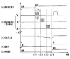
- FIG. 3 is a time chart showing valve opening promotion control at the time of engine start request
- FIG. 4 is a time chart showing valve opening promotion control at the time of fuel switching request
- FIG. 5 is a flowchart showing a processing procedure of valve opening promotion control at the time of an engine start request
- FIG. 6 is a flowchart showing a processing procedure of valve opening promotion control at the time of a fuel switching request
- FIG. 1 is a configuration diagram showing an outline of a fuel injection system of an engine.
- FIG. 2 is a diagram showing a configuration of a power supply system for each electric load
- FIG. 3 is a time chart showing valve opening promotion control at the time of engine start request
- FIG. 4 is a time chart showing valve opening promotion control at the time of fuel switching request
- FIG. 5 is a flowchart showing a processing procedure of
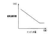
- FIG. 7 is a diagram showing the relationship between engine water temperature and accumulated energization time.
- FIG. 8 is a diagram showing the relationship between the battery voltage and the cumulative energization time.
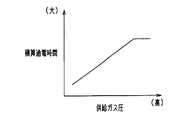
- FIG. 9 is a diagram showing the relationship between the supply gas pressure and the cumulative energization time.
- FIG. 10 is a time chart showing valve opening promotion control of another embodiment,
- FIG. 11 is a time chart showing valve opening promotion control of another embodiment.
- the present embodiment is a fuel injection control applied to a so-called bi-fuel type in-vehicle engine (internal combustion engine) that uses compressed natural gas (CNG) that is a gaseous fuel and gasoline that is a liquid fuel as combustion fuel. It is embodied as a system. An overall schematic diagram of this system is shown in FIG.
- the engine 10 shown in FIG. 1 is a multi-cylinder (for example, in-line three-cylinder) spark ignition engine.
- An intake pipe 11 is connected to the intake port of the engine 10 via an intake manifold 12, and an exhaust pipe 14 is connected to the exhaust port via an exhaust manifold 13.
- the intake pipe 11 is provided with a throttle valve 15 as an air amount adjusting unit.
- the throttle valve 15 is an electronic control type whose opening is adjusted by a throttle actuator 15a such as a DC motor.
- the opening degree of the throttle valve 15 (throttle opening degree) is detected by a throttle opening degree sensor 15b built in the throttle actuator 15a.
- the exhaust pipe 14 is provided with an exhaust sensor for detecting exhaust components and a catalyst 19 for purifying the exhaust.
- an exhaust sensor for detecting exhaust components
- a catalyst 19 for purifying the exhaust.
- oxygen sensors 18a and 18b that output detection signals corresponding to the oxygen concentration in the exhaust are provided on the upstream side and the downstream side of the catalyst 19, respectively.
- the intake port and the exhaust port of the engine 10 are respectively provided with an intake valve 25 and an exhaust valve 26 as engine valves for adjusting the amount of air introduced into the cylinder.
- an intake valve 25 When the intake valve 25 is opened, a mixture of air and fuel is introduced into the cylinder, and when the exhaust valve 26 is opened, the exhaust gas after combustion is discharged into the exhaust passage.
- a spark plug 20 is provided in each cylinder of the engine 10.
- a high voltage is applied to the ignition plug 20 at a desired ignition timing through an ignition device 20a including an ignition coil. By applying this high voltage, a spark discharge is generated between the opposing electrodes of each spark plug 20, and the fuel introduced into the cylinder is ignited and used for combustion.
- a gas fuel injection valve 21 that injects gaseous fuel and a liquid fuel injection valve 22 that injects liquid fuel are provided as fuel injection valves that supply fuel to each cylinder for each cylinder of the engine 10. ing. Each of these injection valves 21 and 22 injects fuel into the intake manifold 12.
- Each of the injection valves 21 and 22 is an open / close type control valve in which the valve body is lifted from the closed position to the open position by electrically driving the electromagnetic drive unit. Each valve is driven to open by a valve opening drive signal. Each of these injection valves 21 and 22 opens by energization and closes by energization interruption, thereby injecting an amount of fuel corresponding to the energization time.
- a fuel conduit 23 is connected to the tip of the gaseous fuel injection valve 21. The gaseous fuel injected from the gaseous fuel injection valve 21 is discharged to the intake manifold 12 through the fuel conduit 23.
- the liquid fuel injection valve 22 is a port injection type in this embodiment, but may be a direct injection type in which fuel is directly injected into the cylinder of the engine 10.
- the gaseous fuel injection valve 21 has a so-called self-sealing structure in which a closing sealing property is imparted by the pressure (supplying gas pressure) of the gaseous fuel supplied to itself.
- the supply gas pressure acts on the valve body to set the valve body at the valve closing position.
- the electromagnetic drive unit When the electromagnetic drive unit is energized, the valve body overcomes the force in the valve closing direction and is displaced in the valve opening direction, thereby opening the injection hole.
- a rubber valve seat portion is provided in the injection hole of the gaseous fuel injection valve 21, and the close sealability when the valve is closed is secured by the close contact between the tip of the valve body and the valve seat portion.
- the gaseous fuel supply unit 40 is provided with a gas tank 42 that stores gaseous fuel in a high pressure state, and a gas pipe 41 that connects the gas tank 42 and the gaseous fuel injection valve 21.
- a regulator 43 is provided as a pressure adjusting unit having a function of reducing the pressure of the gaseous fuel supplied to the gaseous fuel injection valve 21.
- the regulator 43 adjusts the pressure of the gas fuel stored in the gas tank 42 in a high pressure state (for example, a maximum of 20 MPa) so as to become a predetermined set pressure (for example, a constant pressure within a range of 0.2 to 1.0 MPa). It is.
- the gaseous fuel after the decompression adjustment is supplied to the gaseous fuel injection valve 21 through the gas pipe 41.
- the regulator 43 may be a variable fuel pressure type that can variably adjust the pressure of the fuel supplied to the gaseous fuel injection valve 21.
- the gas pipe 41 further includes a tank main stop valve 44 disposed near the fuel outlet of the gas tank 42, and a shut-off valve 45 disposed downstream of the tank main stop valve 44 and near the fuel inlet of the regulator 43. Is provided. These valves 44 and 45 allow and block the flow of gaseous fuel in the gas pipe 41. Both the tank main stop valve 44 and the shut-off valve 45 are electromagnetic on-off valves, and are normally closed types in which the flow of gaseous fuel is blocked when not energized and the flow of gaseous fuel is allowed when energized.
- pressure sensors 46 and 47 for detecting fuel pressure are provided upstream and downstream of the regulator 43, and a temperature sensor 48 for detecting fuel temperature is provided downstream of the regulator 43. Is provided.
- the liquid fuel supply unit 70 is provided with a fuel tank 72 that stores liquid fuel, and the fuel tank 72 is connected to the liquid fuel injection valve 22 via a fuel pipe 71.
- the fuel pipe 71 is provided with a fuel pump 73 for feeding the liquid fuel in the fuel tank 72 to the liquid fuel injection valve 22.
- the liquid fuel pumped up by the fuel pump 73 is supplied to the liquid fuel injection valve 22 through the fuel pipe 71.
- the control unit 80 includes a CPU, a ROM, a RAM, a backup RAM, and the like, and executes various control programs stored in the ROM, thereby performing various controls of the engine 10 according to each engine operating state. .
- the control unit 80 is electrically connected to the various sensors described above and other sensors provided in the system, and outputs (detection signals) from these sensors are input.
- Other sensors include, for example, a crank angle sensor 81 that detects engine rotation speed, an intake pressure sensor 82 that detects intake pipe pressure, a cooling water temperature sensor 83 that detects engine cooling water temperature, a vehicle speed sensor that detects vehicle speed, and the like. is there.
- the control unit 80 is electrically connected to a drive unit such as the ignition device 20a, each injection valve 21, 22 or a starter as a starter of the engine 10, and outputs a drive signal to each drive unit. Control each drive unit. For example, the gaseous fuel injection valve 21 is opened in accordance with a valve opening drive signal that is an injection command from the control unit 80 and injects gaseous fuel.
- the ignition device 20a outputs a high voltage in response to an ignition signal from the control unit 80, and causes an ignition spark in the ignition plug.
- Electrical loads such as the gaseous fuel injection valve 21, the ignition device 20 a, the starter, the tank main stop valve 44, and the shutoff valve 45 operate by receiving power supplied from the on-vehicle battery.
- the configuration of the power supply system is shown in FIG. In FIG. 2, the gaseous fuel injection valve 21, the ignition device 20 a, the tank main stop valve 44, the shutoff valve 45, and the starter 84 of each cylinder as an electric load are connected to a battery 93 as a power supply unit via a power supply line 92.
- the starter 84 is switched between a power supply state and a power cut-off state by a driver operation (for example, key operation). Each of these electric loads is driven by power supply from the battery 93.
- an ON / OFF signal of an ignition switch (IG switch 85) as a start switch of the engine 10 operated by a driver is input to the control unit 80.
- the control unit 80 selectively switches the fuel used for the operation of the engine 10 according to the engine operating state, the fuel remaining amount in the tank, an input signal from a fuel selection switch (not shown), and the like. Specifically, when the use of gaseous fuel is selected by the fuel selection switch or when the remaining amount of liquid fuel in the fuel tank 72 falls below a predetermined value, the gaseous fuel supply is performed as the operation mode of the engine 10. The gaseous fuel mode in which gaseous fuel is supplied to the engine 10 by the unit 40 is selected. On the other hand, when the use of the liquid fuel is selected by the fuel selection switch or when the remaining amount of the gaseous fuel in the gas tank 42 falls below a predetermined value, the liquid fuel supply unit 70 sets the liquid as the operation mode of the engine 10. A liquid fuel mode for supplying fuel to the engine 10 is selected.
- the injection hole of the gaseous fuel injection valve 21 is generally provided with a rubber valve seat portion as a measure against fuel leakage.
- the driving of the gaseous fuel injection valve 21 is stopped, and the tip of the valve body and the valve seat are in close contact with each other. If the gaseous fuel injection valve 21 is commanded to be injected from such a state, the gaseous fuel may not be immediately injected from the gaseous fuel injection valve 21.
- the valve body tends to be fixed to the valve seat portion due to the hardening of the rubber. Further, when the supply gas pressure is high, the valve body may be pressed against the valve seat portion by the fuel pressure, and the sticking of the valve body may be promoted.
- the gaseous fuel is injected from the gaseous fuel injection valve 21 prior to the energization control for injecting gaseous fuel from the gaseous fuel injection valve 21.
- Pre-energization control for energizing the gaseous fuel injection valve 21 to such an extent that it does not occur is performed.
- the operation start request of the engine 10 using gaseous fuel includes (1) a start request for starting the engine 10 using gaseous fuel, and (2) fuel switching for switching the fuel used from liquid fuel to gaseous fuel during engine operation with liquid fuel. Including requests.
- the pre-energization control corresponds to valve opening promotion control
- the control unit 80 that executes the pre-energization control corresponds to an energization control unit.
- FIG. 3 shows a case where an engine start request using gaseous fuel is generated
- FIG. 4 shows a case where a fuel switching request from liquid fuel to gaseous fuel is generated.
- FIG. 3 shows the change in the valve opening drive signal of the gaseous fuel injection valve 21
- (b) shows the change in the supply gas pressure of the gaseous fuel injection valve 21
- (c) shows the change in the opening and closing of the shutoff valve 45.
- energization for promoting valve opening is performed on the gaseous fuel injection valve 21 (time t11). Specifically, as shown in FIG. 3, a pulse having a predetermined width W that is short enough not to inject fuel from the gaseous fuel injection valve 21 is output. In particular, in this embodiment, energization on / off is repeated by continuously outputting a plurality of pulses having a predetermined width W. At this time, energization for promoting valve opening is sequentially performed on the gaseous fuel injection valve 21 of each cylinder one by one.
- the combustion order is the order of the first cylinder (# 1), the second cylinder (# 2), and the third cylinder (# 3).
- the gas fuel injection valve 21 of each cylinder is given.
- Energize to promote valve opening Specifically, first, energization for valve opening promotion is performed on the gaseous fuel injection valve 21 of the first cylinder during a predetermined energization period TB from time t11. Next, at time t12 when a predetermined period TA has elapsed from time t11, energization for promoting the opening of the gas fuel injection valve 21 of the second cylinder is started, and pulses having a predetermined width W are continuously applied during the predetermined energization period TB.
- the energization for promoting valve opening is similarly performed on the gaseous fuel injection valve 21 of the third cylinder (time t13).
- the predetermined period TA one stroke of one combustion cycle is set, and 240 ° C. is set for a three-cylinder engine.
- the length of the predetermined period TA is not limited to this, and may be longer or shorter than the length of one stroke.
- the valve opening determination is performed for each cylinder with respect to the gaseous fuel injection valve 21 of each cylinder based on the amount of decrease in the supply gas pressure at this time. Specifically, when the decrease amount ⁇ P of the supply gas pressure is larger than the determination value, it is determined that the gas fuel injection valve 21 of the corresponding cylinder is opened by energization for valve opening promotion.
- the shut-off valve 45 and the tank main stop valve 44 are opened (time). t14). Further, after the cylinder discrimination is completed, an injection command is issued to the gaseous fuel injection valve 21, and the engine 10 is started with the gaseous fuel (from time t15).
- energization control for promoting valve opening is performed on the gaseous fuel injection valve 21 while the fuel used remains liquid.
- energization control for successively outputting a plurality of pulses having a predetermined width W that is short enough not to inject fuel from the gaseous fuel injection valve 21 is sequentially performed for each cylinder in the same manner as when the engine start is requested. .
- the fuel used Is switched from liquid fuel to gaseous fuel (time t24). Specifically, the fuel injection by the liquid fuel injection valve 22 is stopped, and the shutoff valve 45 and the tank main stop valve 44 are opened to instruct the gaseous fuel injection valve 21 to inject.
- 101 it is determined whether or not a request for starting the engine 10 using gaseous fuel has occurred.
- 101 it is determined that there is a request for starting the engine 10 by the gaseous fuel when the two conditions are satisfied after the IG switch 85 is turned on and the gaseous fuel mode is selected.
- 101 corresponds to a request determination unit.
- the routine proceeds to 102, where it is determined whether or not the supply gas pressure detected by the pressure sensor 47 is lower than a predetermined value.
- the process proceeds to 103 and the shutoff valve 45 is maintained in a closed state.
- the routine proceeds to 104, where the shut-off valve 45 is temporarily opened for a predetermined time, and then the shut-off valve 45 is closed.
- 102 corresponds to a pressure determination unit.
- the reason why the processes 102 to 104 are performed is as follows.
- control for lowering the supply gas pressure in advance immediately before turning off the IG switch may be performed.
- the supply gas pressure may be low at the next engine start request.
- the change in the supply gas pressure accompanying energization for valve opening promotion is small, and the accuracy of the valve opening determination may be reduced.
- the supply gas pressure is reduced by temporarily opening the shutoff valve 45. Increase.
- the tank main stop valve 44 may be temporarily opened or may be kept closed.
- 105 it is determined whether cylinder discrimination is incomplete. If the cylinder discrimination is completed, this routine is finished as it is. In this case, an injection command for starting the engine is issued to the gaseous fuel injection valve 21 regardless of whether or not energization for valve opening promotion is completed. That is, when the cylinder discrimination is completed, an attempt is made to inject gaseous fuel at that time. Note that the fuel used may be switched to liquid fuel and the engine may be started with liquid fuel.
- 106 it is determined whether the starting water temperature of the engine 10 is lower than a predetermined value.
- 107 it is determined whether or not the voltage of the battery 93 is higher than a predetermined value.
- the battery voltage is detected by a voltage sensor (not shown).
- 108 it is determined whether or not the elapsed time since the IG switch 85 is turned on is shorter than the predetermined time T1.
- the predetermined time T1 a time longer than the time T2 required for cylinder discrimination is set.
- this routine is terminated as it is. In this case, energization for valve opening promotion is not carried out, and an injection command is given to the gaseous fuel injection valve 21. At this time, it is good also as a structure which switches an operating fuel to a liquid fuel and starts an engine with a liquid fuel.
- an affirmative determination is made in all of 106, 107, and 108, the process proceeds to 108, and energization for promoting valve opening is performed on the gaseous fuel injection valve 21.
- a predetermined value for example, 2 or more. If an affirmative determination is made at 110, the routine proceeds to 111, where the engine 10 is started with gaseous fuel. On the other hand, when a negative determination is made at 110, the routine proceeds to 112 and the engine 10 is started with the liquid fuel.
- step 201 it is determined whether or not a fuel switching request from liquid fuel to gaseous fuel has occurred. If there is no switching request, this routine is terminated as it is, and if there is a switching request, the routine proceeds to 202. In steps 202 to 204, the same processing as in steps 102 to 104 in FIG. 5 is executed, and in step 205, it is determined whether or not the battery voltage is higher than a predetermined value. If an affirmative determination is made in 205, the process proceeds to 206, and energization for promoting valve opening is performed on the gaseous fuel injection valve 21. At this time, the engine 10 is kept operating with the liquid fuel.
- 207 it is determined whether or not the number of cylinders in which the pressure drop amount ⁇ P of the supply gas pressure accompanying energization for valve opening promotion is greater than a predetermined value is greater than or equal to a predetermined value (eg, 2 or more). If an affirmative determination is made in 207, the operation proceeds to 208 and the fuel used is switched to gaseous fuel. On the other hand, if a negative determination is made in 207, the process proceeds to 209 and the engine operation is continued with the fuel used being the liquid fuel.
- a predetermined value eg, 2 or more
- the integrated energization time (the integrated value of energization on time) in energization for valve opening promotion is made variable.
- the cumulative energization time is lengthened as the water temperature at the start is lower (FIG. 7).
- the lower the battery voltage the longer the integrated energization time (FIG. 8), and the higher the supply gas pressure, the longer the integrated energization time (FIG. 9).
- the cumulative energization time is made variable by setting the number of times of output of pulses having a predetermined width W to be variable. That is, the cumulative energization time is lengthened by increasing the number of outputs of the predetermined width W.
- the gas fuel injection valve 21 When a request to start operation of the engine 10 is generated, the gas fuel injection valve 21 is energized to an extent that the gaseous fuel is not injected from the gaseous fuel injection valve 21 prior to an injection command for injecting gaseous fuel from the gaseous fuel injection valve 21.
- the valve promotion control is implemented. Thereby, the valve opening of the gaseous fuel injection valve 21 can be promoted, and when the injection command is given, the gaseous fuel can be properly supplied to the engine 10. As a result, the operation can be started promptly in response to a request for starting the operation of the engine 10 using gaseous fuel.
- the start request for starting the engine 10 with gaseous fuel is generated as an operation start request for the engine 10
- energization for promoting valve opening is performed.
- the engine 10 is started, it is driven from a state in which the gas fuel injection valve 21 is kept closed. Therefore, when the engine start request is generated, the valve body of the gas fuel injection valve 21 is stretched on the valve seat portion. It may be attached.
- the rubber portion of the valve seat portion is cured, so that the valve body is easily fixed to the valve seat portion, and the above-described matters are likely to occur.
- the startability of the engine 10 can be improved by energizing the gaseous fuel injection valve 21 for energization before the injection command for starting the engine is performed.
- the valve opening promotion control is performed when a fuel switching request for switching the used fuel to the gaseous fuel occurs when the engine 10 is operated with liquid fuel.
- the driving is performed from the state in which the gaseous fuel injection valve 21 is kept closed. Therefore, when the fuel switching is requested, the valve body of the gaseous fuel injection valve 21 is in close contact with the valve seat portion. May have.
- a configuration is adopted in which the fuel used is switched to gaseous fuel.
- the energization for promoting the opening of the valve is performed in such a manner that the gaseous fuel is not injected from the gaseous fuel injection valve 21. Therefore, even if it is performed during the engine operation with the liquid fuel, the fuel does not become excessive and the output fluctuation does not occur. Further, it is not necessary to perform complicated control such as liquid fuel reduction correction for suppressing excessive fuel.
- a plurality of pulses having a predetermined width W in which gaseous fuel is not injected from the gaseous fuel injection valve 21 are continuously output.
- energization for valve opening promotion is performed. If energization for valve opening promotion is performed when the battery voltage is low, the engine 10 cannot be started due to a shortage of power supplied to the starter 84. In particular, when the engine 10 is cold-started, the performance of the battery 93 tends to decrease, and the influence on the startability of the engine 10 is great. In view of these points, with the above-described configuration, energization for promoting valve opening can be performed while ensuring the startability of the engine 10.
- a valve opening determination process is performed to determine whether the gaseous fuel injection valve 21 has been opened by energization for valve opening promotion. Based on the determination result, A configuration for determining whether or not the engine operation with gaseous fuel is permitted.
- the sticking of the valve body of the gaseous fuel injection valve 21 is canceled by energization for valve opening promotion and the injection hole is opened, the gaseous fuel leaks from the injection hole, so that the supply gas pressure is lowered.
- the control unit 80 corresponds to a valve opening determination unit that determines whether or not the gaseous fuel injection valve 21 is opened.
- the energization for opening the valve is performed after the shut-off valve 45 is temporarily opened.
- the gas fuel injection valve 21 of each cylinder is configured to energize the valve opening promotion one by one in order, the decrease in the supply gas pressure accompanying the valve opening promoting energization is detected one cylinder at a time. can do. Thereby, it is possible to discriminate between a cylinder that reliably injects fuel by an injection command and a cylinder that may not inject fuel.
- the cumulative energization time for energization for valve opening promotion is made longer as the engine temperature is lower.
- the degree of sticking between the valve body and the valve seat of the gaseous fuel injection valve 21 becomes stronger, and the gaseous fuel injection valve 21 is less likely to open.
- the lower the battery voltage the longer the integrated energization time for energization for valve opening promotion.
- the gaseous fuel injection valve 21 is more difficult to open.
- the gas fuel injection valve 21 can be energized according to the difficulty in opening the gaseous fuel injection valve 21 due to the battery voltage.
- the integrated energization time in energization for valve opening promotion is made longer as the supply gas pressure of the gaseous fuel injection valve 21 is higher.
- the valve body is pressed against the valve seat portion by the fuel pressure, and the sticking of the valve body may be promoted. Considering these points, by adopting the above configuration, it is possible to energize according to the difficulty in opening the gaseous fuel injection valve 21 due to the supply gas pressure.
- the energization control for promoting valve opening may be an aspect in which the gaseous fuel injection valve 21 is energized with supply power that does not cause the gaseous fuel to be injected from the gaseous fuel injection valve 21.
- a pulse having a predetermined width that is short enough not to inject fuel from the gaseous fuel injection valve 21 may be output only once.
- the energization for promoting valve opening is sequentially performed on the gas fuel injection valves 21 of each cylinder one by one.
- the gas fuel injection valves 21 for all cylinders are simultaneously used for promoting valve opening. May be energized.
- the first cylinder (# 1), the second cylinder (# 2), and the third cylinder (# Energization for valve opening promotion is simultaneously performed for all the cylinders in 3).
- Such a configuration is desirable in that the valve opening promotion control can be performed in a short time, and the engine operation with gaseous fuel can be started at an early stage. At this time, it is good also as a structure which implements valve opening determination based on the fall amount of the supply gas pressure accompanying the electricity supply for valve opening promotion like the said embodiment.
- the gas fuel injection valves 21 of the first cylinder to the third cylinder are energized once for the valve opening promotion, but each of the injection valves 21 is performed a plurality of times. It is good also as a structure to implement. Moreover, it is good also as a structure which implements electricity supply for valve-opening promotion until it determines with the gaseous fuel injection valve 21 of all the cylinders having opened.
- the control unit 80 corresponds to a permission unit that permits operation of the engine 10 using gaseous fuel.
- the engine operation with the gaseous fuel is performed on the condition that the number of the gaseous fuel injection valves 21 opened by energization for promoting the opening of the valve is a predetermined number or more. After energization for promotion, it is good also as composition which carries out engine operation by gaseous fuel. If energization for valve opening promotion is performed before the injection command, even if sticking to the valve seat portion of the valve body of the gaseous fuel injection valve 21 is not eliminated, the degree can be reduced. . Therefore, when the injection command is issued without performing the valve opening determination process, the gaseous fuel injection valve 21 is easy to open, and it is fully conceivable that the fuel is injected from the gaseous fuel injection valve 21.
- the timing for starting energization for promoting valve opening in response to a request for starting the operation of the engine 10 using gaseous fuel is not particularly limited as long as it is performed prior to the injection command.
- a predetermined time has elapsed since the request for starting operation occurred. It is good also as a structure which starts electricity supply for valve opening promotion at the timing which did.
- the energization for valve opening promotion is performed prior to the first injection command after the start request. If this was changed and the engine was not started without energizing the valve opening promotion, but the engine could not be started, the valve opening promoting current was applied prior to the next injection command. It is good also as a structure to implement.
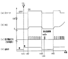
- FIG. 11 is a time chart showing a specific mode of valve opening promotion control of this embodiment.
- (a) shows the transition of driving or stopping of the starter 84
- (b) shows the transition of engine rotation speed
- (c) shows the transition of the valve opening drive signal of the gaseous fuel injection valve 21, and
- (d) shows the cutoff.
- the transition of opening and closing of the valve 45 is shown. Note that (c) shows a valve opening drive signal for only one cylinder.
- the shutoff valve 45 and the tank main stop valve 44 are opened when the IG switch 85 is turned on (time t41). Subsequently, the starter 84 is turned on by the operation of the driver, and an injection command is output to the gaseous fuel injection valve 21. At this time, a case is considered in which the gas fuel injection valve 21 is not driven to open even if a valve opening drive signal is output to the gas fuel injection valve 21. In this case, energization for valve opening promotion is performed immediately after the starter drive is temporarily turned off at time t43 in accordance with the operation of the driver (time t44).
- energization for valve opening promotion for example, a plurality of pulses having a predetermined width W that are short enough not to inject fuel from the gaseous fuel injection valve 21 are continuously output. Then, after the starter 84 is re-driven at time t45 in accordance with the operation of the driver, the gaseous fuel injection valve 21 is easily opened by energization for valve opening promotion, and an appropriate amount of gaseous fuel is injected from the injection hole. Then, the engine 10 is started.
- first valve opening promotion control When energization for valve opening promotion (first valve opening promotion control) is performed at the timing when the start request of the engine 10 by the gaseous fuel occurs, the starter 84 is driven when the engine 10 cannot be started despite that.
- second valve opening promotion control After stopping once, energization for valve opening promotion (second valve opening promotion control) may be performed.
- the energization mode of the second valve opening promotion control may be the same as or different from the energization mode of the first valve opening promotion control.
- the integrated energization time (such as the number of pulse outputs) may be increased so that the valve is more easily opened.
- the integrated energization time of the valve opening promotion control is variably set, but may be a predetermined time.
- the present invention is applied to a three-cylinder engine.
- the number of cylinders is merely an example, and the present invention may be applied to a multi-cylinder engine such as a four-cylinder engine, a six-cylinder engine, or an eight-cylinder engine.
- the fuel conduit 23 is connected to the tip of the gaseous fuel injection valve 21, and the gaseous fuel injected from the gaseous fuel injection valve 21 is discharged to the intake passage via the fuel conduit 23.
- the gaseous fuel injection valve 21 may be configured to inject gaseous fuel directly into the intake passage.
- the present invention is applied to a bi-fuel type vehicle-mounted engine that uses gaseous fuel and liquid fuel as fuel for engine combustion, but may be applied to a gas-only vehicle-mounted engine that uses only gaseous fuel.
- valve opening promotion control is performed when there is a start request for starting the engine 10 with gaseous fuel as a request for starting operation of the engine 10 with gaseous fuel.
- the starter 84 is not limited to a configuration in which driving or driving stop is switched by an operation of the driver, but may be one that can arbitrarily control the timing of starter driving. In this case, the combustion control (injection and ignition) of the engine 10 can be started after the valve-opening promotion control has been ended with certainty.
- a plurality of gaseous fuel injection valves 21 are provided for each cylinder of a multi-cylinder engine.
- the gaseous fuel injection valves 21 are provided in a common part of a plurality of cylinders, and the intake system collective portion is provided. It is good also as a structure which injects gaseous fuel.
- the valve opening promotion control may be performed sequentially for the gas fuel injection valves 21 of each cylinder one by one, or may be performed simultaneously for the gas fuel injection valves 21 of all cylinders.
- the gaseous fuel is CNG fuel, but other gaseous fuels that are gaseous in the standard state can also be used.
- the liquid fuel is not limited to gasoline, and for example, light oil or the like may be used.
Landscapes
- Engineering & Computer Science (AREA)
- Chemical & Material Sciences (AREA)
- Combustion & Propulsion (AREA)
- Mechanical Engineering (AREA)
- General Engineering & Computer Science (AREA)
- Oil, Petroleum & Natural Gas (AREA)
- Chemical Kinetics & Catalysis (AREA)
- General Chemical & Material Sciences (AREA)
- Output Control And Ontrol Of Special Type Engine (AREA)
- Electrical Control Of Air Or Fuel Supplied To Internal-Combustion Engine (AREA)
Abstract
燃料噴射制御装置は、気体燃料を噴射する気体燃料噴射弁(21)を備える内燃機関(10)に適用され、気体燃料による内燃機関の運転開始要求が生じたか否かを判定する要求判定部(80、101)と、要求判定部により運転開始要求が生じたと判定された場合に、気体燃料噴射弁から気体燃料を噴射させる噴射指令に先立ち、気体燃料噴射弁から気体燃料を噴射させない程度に気体燃料噴射弁に通電するプレ通電制御を実施する通電制御部(80、201~209)と、を備える。
Description
本出願は、2015年2月20日に出願された日本特許出願番号2015-32009号に基づくもので、ここにその記載内容を援用する。
本開示は、気体燃料を燃料噴射弁に供給可能な燃料供給系を備える内燃機関の燃料噴射制御装置に関するものである。
従来、例えば圧縮天然ガス(CNG)等の気体燃料を燃焼させて駆動する内燃機関が実用化されている。ここで、エンジンを始動する際には、噴射弁と弁座との張り付き(固着)が生じていることがある。この点について、特許文献1には、気体燃料噴射弁が固着していると判定されているときには、エンジン始動時の気体燃料圧力を通常運転時よりも低くするとともに、通電時間を通常運転時よりも長くすることが開示されている。こうした制御により、噴射弁と弁座との張り付きの解消を促進させる。
エンジン始動時には、通常、気筒判別が完了した後に噴射指令を行い、この噴射指令に伴い燃料噴射弁から燃料が噴射されてエンジンで燃焼が行われる。上記特許文献1に記載の制御のように通電時間を長くする場合、エンジン始動に要する時間が長くなるおそれがある。
本開示は、気体燃料による内燃機関の運転開始要求に伴い、内燃機関の運転を速やかに開始することができる燃料噴射制御装置を提供することを目的とする。
本開示の一態様により、燃料噴射制御装置は、気体燃料を噴射する気体燃料噴射弁を備える内燃機関に適用され、気体燃料による内燃機関の運転開始要求が生じたか否かを判定する要求判定部と、要求判定部により運転開始要求が生じたと判定された場合に、気体燃料噴射弁から気体燃料を噴射させる噴射指令に先立ち、気体燃料噴射弁から気体燃料を噴射させない程度に気体燃料噴射弁に通電するプレ通電制御を実施する通電制御部と、を備える。
上記構成では、内燃機関の運転開始要求に伴い気体燃料で内燃機関を運転する場合には、気体燃料噴射弁に噴射指令する前に予め、気体燃料噴射弁から気体燃料を噴射させない程度に気体燃料噴射弁に通電しておく。こうした通電制御により、気体燃料噴射弁の開弁を促進することができ、噴射指令した際に内燃機関への気体燃料の供給を適正に行わせることができる。その結果、気体燃料による内燃機関の運転開始要求に伴い、内燃機関の運転を速やかに開始することができる。
本開示についての上記目的およびその他の目的、特徴や利点は、添付の図面を参照しながら下記の詳細な記述により、より明確になる。その図面は、
図1は、エンジンの燃料噴射システムの概略を示す構成図であり、
図2は、各電気負荷に対する電力供給系の構成を示す図であり、
図3は、エンジン始動要求時の開弁促進制御を示すタイムチャートであり、
図4は、燃料切替要求時の開弁促進制御を示すタイムチャートであり、
図5は、エンジン始動要求時の開弁促進制御の処理手順を示すフローチャートであり、
図6は、燃料切替要求時の開弁促進制御の処理手順を示すフローチャートであり、
図7は、エンジン水温と積算通電時間との関係を示す図であり、
図8は、バッテリ電圧と積算通電時間との関係を示す図であり、
図9は、供給ガス圧と積算通電時間との関係を示す図であり、
図10は、他の実施形態の開弁促進制御を示すタイムチャートであり、
図11は、他の実施形態の開弁促進制御を示すタイムチャートである。
以下、実施形態について図面を参照しつつ説明する。本実施形態は、気体燃料である圧縮天然ガス(CNG)と、液体燃料であるガソリンとを燃焼用の燃料として使用する、いわゆるバイフューエルタイプの車載エンジン(内燃機関)に適用される燃料噴射制御システムとして具体化している。本システムの全体概略図を図1に示す。
図1に示すエンジン10は、多気筒(例えば直列3気筒)の火花点火式エンジンである。エンジン10の吸気ポートには吸気マニホールド12を介して吸気管11が接続されており、排気ポートには排気マニホールド13を介して排気管14が接続されている。吸気管11には、空気量調整部としてのスロットル弁15が設けられている。スロットル弁15は、DCモータ等のスロットルアクチュエータ15aにより開度調節される電子制御式である。スロットル弁15の開度(スロットル開度)は、スロットルアクチュエータ15aに内蔵されたスロットル開度センサ15bにより検出される。
排気管14には、排気の成分を検出する排気センサと、排気を浄化する触媒19とが設けられている。排気センサとしては、排気中の酸素濃度に応じた検出信号を出力する酸素センサ18a,18bが、触媒19の上流側及び下流側にそれぞれ設けられている。
エンジン10の吸気ポート及び排気ポートには、気筒内に導入される空気量を調整する機関バルブとしての吸気バルブ25及び排気バルブ26がそれぞれ設けられている。吸気バルブ25の開動作により空気と燃料との混合気が気筒内に導入され、排気バルブ26の開動作により燃焼後の排気が排気通路に排出される。
エンジン10の各気筒には点火プラグ20が設けられている。点火プラグ20には、点火コイル等よりなる点火装置20aを通じて、所望とする点火時期に高電圧が印加される。この高電圧の印加により、各点火プラグ20の対向電極間に火花放電が発生し、気筒内に導入した燃料が着火され燃焼に供される。
本システムには、エンジン10の気筒ごとに、燃料を各気筒に供給する燃料噴射弁として、気体燃料を噴射する気体燃料噴射弁21と、液体燃料を噴射する液体燃料噴射弁22とが設けられている。これら各噴射弁21,22は、吸気マニホールド12に燃料を噴射する。
各噴射弁21,22は、電磁駆動部が電気的に駆動されることで弁体が閉位置から開位置にリフトされる開閉タイプの制御弁であり、制御部80から入力されるオン/オフ式の開弁駆動信号によりそれぞれ開弁駆動される。これら各噴射弁21,22は、通電により開弁し、通電遮断により閉弁することにより、通電時間に応じた量の燃料を噴射する。本実施形態では、気体燃料噴射弁21の先端部に燃料導管23が接続されている。気体燃料噴射弁21から噴射された気体燃料は、燃料導管23を介して吸気マニホールド12に放出される。液体燃料噴射弁22について本実施形態ではポート噴射式であるが、エンジン10の気筒内に直接燃料を噴射する直噴式としてもよい。
気体燃料噴射弁21について詳しくは、自身に供給される気体燃料の圧力(供給ガス圧)により閉鎖シール性が付与されるいわゆるセルフシール(自密閉)構造を有している。具体的には、気体燃料噴射弁21の閉弁状態では、供給ガス圧が弁体に作用することで弁体を閉弁位置に定めている。そして、電磁駆動部が通電されると、弁体が閉弁方向の力に打ち勝って開弁方向に変位し、これにより噴射孔が開弁状態になる。気体燃料噴射弁21の噴射孔にはゴム製の弁座部が設けられており、弁体の先端部と弁座部とが密着することにより、閉弁時における閉鎖シール性が確保される。
次に、気体燃料噴射弁21に対して気体燃料を供給する気体燃料供給部40と、液体燃料噴射弁22に対して液体燃料を供給する液体燃料供給部70とについて説明する。
気体燃料供給部40には、気体燃料を高圧状態で貯留するガスタンク42と、ガスタンク42と気体燃料噴射弁21とを接続するガス配管41とが設けられている。ガス配管41の途中には、気体燃料噴射弁21に供給される気体燃料の圧力を減圧調整する機能を有する圧力調整部としてのレギュレータ43が設けられている。レギュレータ43は、ガスタンク42内に貯蔵された高圧状態(例えば最大20MPa)の気体燃料を所定の設定圧(例えば0.2~1.0MPaの範囲内の一定圧)になるように減圧調整するものである。減圧調整後の気体燃料は、ガス配管41を通って気体燃料噴射弁21に供給される。なお、レギュレータ43は、気体燃料噴射弁21に供給する燃料の圧力を可変調整可能な可変燃圧式であってもよい。
ガス配管41には更に、ガスタンク42の燃料出口付近に配置されたタンク主止弁44と、タンク主止弁44よりも下流側であってレギュレータ43の燃料入口付近に配置された遮断弁45とが設けられている。これら各弁44,45によって、ガス配管41における気体燃料の流通が許容及び遮断される。タンク主止弁44及び遮断弁45はいずれも電磁式の開閉弁であり、非通電時において気体燃料の流通が遮断され、通電時において気体燃料の流通が許容される常閉式である。また、ガス配管41において、レギュレータ43の上流側及び下流側には、燃料圧力を検出する圧力センサ46,47が設けられており、レギュレータ43の下流側には、燃料温度を検出する温度センサ48が設けられている。
液体燃料供給部70には、液体燃料を貯留する燃料タンク72が設けられており、燃料タンク72が液体燃料噴射弁22に燃料配管71を介して接続されている。燃料配管71には、燃料タンク72内の液体燃料を液体燃料噴射弁22に給送する燃料ポンプ73が設けられている。燃料ポンプ73により汲み上げられた液体燃料は、燃料配管71を通って液体燃料噴射弁22に供給される。
制御部80は、CPU、ROM、RAM、バックアップRAM等を備えており、ROMに記憶された各種の制御プログラムを実行することで、都度のエンジン運転状態に応じてエンジン10の各種制御を実施する。具体的には、制御部80は、上述した各種センサや、本システムに設けられたその他のセンサと電気的に接続されており、これらのセンサからの出力(検出信号)が入力される。その他のセンサとしては、例えばエンジン回転速度を検出するクランク角センサ81、吸気管圧力を検出する吸気圧センサ82、エンジン冷却水の温度を検出する冷却水温センサ83、車速を検出する車速センサ等がある。
制御部80は、点火装置20a、各噴射弁21,22や、エンジン10の始動装置としてのスタータ等の駆動部と電気的に接続されており、駆動信号を各駆動部に向けて出力することにより各駆動部を制御する。例えば、気体燃料噴射弁21は、制御部80からの噴射指令である開弁駆動信号に応じて開弁し、気体燃料を噴射する。点火装置20aは、制御部80からの点火信号に応じて高電圧を出力し、点火プラグに点火火花を生じさせる。
気体燃料噴射弁21や点火装置20a、スタータ、タンク主止弁44、遮断弁45などの電気負荷は車載バッテリからの電力供給を受けて作動する。その電力供給系の構成を図2に示す。図2では、電気負荷としての各気筒の気体燃料噴射弁21や点火装置20a、タンク主止弁44、遮断弁45、スタータ84が電力供給線92を介して、電源部としてのバッテリ93に接続されている。スタータ84は、ドライバの操作(例えばキー操作)によって電力供給状態及び電力遮断状態が切り替えられる。これら各電気負荷は、バッテリ93からの電力供給により駆動される。また、制御部80には、ドライバによって操作されるエンジン10の始動スイッチとしてのイグニッションスイッチ(IGスイッチ85)のオン/オフ信号が入力される。
制御部80は、エンジン運転状態やタンク内の燃料残量、図示しない燃料選択スイッチからの入力信号等に応じて、エンジン10の運転に使用する燃料を選択的に切り替えている。具体的には、燃料選択スイッチにより気体燃料の使用が選択されている場合又は燃料タンク72内の液体燃料の残存量が所定値を下回った場合には、エンジン10の運転モードとして、気体燃料供給部40により気体燃料をエンジン10に供給する気体燃料モードを選択する。一方、燃料選択スイッチにより液体燃料の使用が選択されている場合又はガスタンク42内の気体燃料の残存量が所定値を下回った場合には、エンジン10の運転モードとして、液体燃料供給部70により液体燃料をエンジン10に供給する液体燃料モードを選択する。
ここで、気体燃料噴射弁21の噴射孔には一般に、燃料リーク対策としてゴム製の弁座部が設けられている。エンジン停止中や液体燃料によるエンジン運転中では、気体燃料噴射弁21の駆動は停止しており、弁体の先端部と弁座部とが密着した状態になっている。こうした状態から気体燃料噴射弁21に噴射指令した場合、気体燃料噴射弁21から直ちに気体燃料が噴射されないことがある。特に、低温時のエンジン始動では、ゴムの硬化により弁体が弁座部に固着した状態となりやすい。また、供給ガス圧が高いと、弁体が燃料圧力によって弁座部に押し付けられ、弁体の固着を助長することがある。
そこで本実施形態では、気体燃料によるエンジン10の運転開始要求が生じた場合に、気体燃料噴射弁21から気体燃料を噴射させる噴射用の通電制御に先立ち、気体燃料噴射弁21から気体燃料を噴射させない程度に気体燃料噴射弁21に通電するプレ通電制御を実施する。気体燃料によるエンジン10の運転開始要求としては、(1)気体燃料によりエンジン10を始動させる始動要求、及び(2)液体燃料でのエンジン運転中に使用燃料を液体燃料から気体燃料に切り替える燃料切替要求、を含む。本実施形態では、プレ通電制御は開弁促進制御に相当し、プレ通電制御を実行する制御部80は通電制御部に相当する。
本実施形態の開弁促進制御について図3及び図4のタイムチャートを用いて説明する。図3は、気体燃料によるエンジン始動要求が生じた場合を示し、図4は、液体燃料から気体燃料への燃料切替要求が生じた場合を示す。なお、図3中、(a)は気体燃料噴射弁21の開弁駆動信号の推移、(b)は気体燃料噴射弁21の供給ガス圧の推移、(c)は遮断弁45の開閉の推移、をそれぞれ示している。図4中、(a)は燃料切替要求の推移、(b)は気体燃料噴射弁21の開弁駆動信号の推移、(c)は気体燃料噴射弁21の供給ガス圧の推移、(d)は遮断弁45の開閉の推移、(e)は使用燃料の推移、をそれぞれ示している。図3及び図4では、第n気筒を「♯n」と示している。
図3において、気体燃料によるエンジン10の始動要求(例えばIGスイッチ85のオン信号の入力)があると、まず、気体燃料噴射弁21に対し開弁促進用の通電を実施する(時刻t11)。具体的には、図3に示すように、気体燃料噴射弁21から燃料が噴射されない程度に短い所定幅Wのパルスを出力する。特に本実施形態では、所定幅Wのパルスを複数個連続的に出力することにより通電オン/オフを繰り返す。このとき、各気筒の気体燃料噴射弁21に対して、1気筒ずつ順に開弁促進用の通電を実施する。
本実施形態では、燃焼順序を第1気筒(♯1)、第2気筒(♯2)、第3気筒(♯3)の順としており、この燃焼順序に従って、各気筒の気体燃料噴射弁21に対して開弁促進用の通電を行う。具体的には、まず、時刻t11から所定の通電期間TBの間において、第1気筒の気体燃料噴射弁21に対して開弁促進用の通電を実施する。次いで、時刻t11から所定期間TAが経過した時刻t12で、第2気筒の気体燃料噴射弁21に対する開弁促進用の通電を開始し、所定の通電期間TBの間、所定幅Wのパルスを連続的に出力する。その後、第3気筒の気体燃料噴射弁21に対しても同様に開弁促進用の通電を実施する(時刻t13)。所定期間TAとしては、1燃焼サイクルの1行程分が設定されており、3気筒エンジンであれば240℃Aが設定されている。なお、所定期間TAの長さはこれに限らず、1行程分の長さより長くてもよいし短くてもよい。
開弁促進用の通電により弁体が開弁方向に動き、弁座部から離間すると、気体燃料噴射弁21の噴射孔から燃料が漏れ出ることにより供給ガス圧が低下する。本実施形態では、このときの供給ガス圧の低下量に基づいて、各気筒の気体燃料噴射弁21について気筒ごとに開弁判定を行う。具体的には、供給ガス圧の低下量ΔPが判定値よりも大きい場合に、対応する気筒の気体燃料噴射弁21が開弁促進用の通電によって開弁したものと判定する。そして、所定の気筒数以上(3気筒エンジンの場合、例えば2つ以上)の気体燃料噴射弁21が開弁したと判定されると、遮断弁45及びタンク主止弁44を開弁する(時刻t14)。また、気筒判別が完了した後に気体燃料噴射弁21に噴射指令して、気体燃料でエンジン10を始動する(時刻t15~)。
次に、気体燃料への燃料切替要求が生じた場合について説明する。図4において、液体燃料を用いてのエンジン運転中に燃料の切替要求が発生すると、使用燃料を液体燃料としたままの状態で、気体燃料噴射弁21に対して開弁促進用の通電制御を実施する(時刻t21)。開弁促進用の通電については、エンジン始動要求時と同じく、気体燃料噴射弁21から燃料が噴射されない程度に短い所定幅Wのパルスを複数個連続的に出力する通電制御を1気筒ずつ順に行う。第1気筒(♯1)~第3気筒(♯3)のそれぞれについて開弁促進用の通電を行い、所定の気筒数以上の気体燃料噴射弁21が開弁したと判定されると、使用燃料を液体燃料から気体燃料に切り替える(時刻t24)。具体的には、液体燃料噴射弁22による燃料噴射を停止するとともに、遮断弁45及びタンク主止弁44を開弁して気体燃料噴射弁21に噴射指令する。
次に、本実施形態の開弁促進制御の処理手順についてフローチャートを用いて説明する。まずは、気体燃料によるエンジン10の始動要求が生じた場合について図5を用いて説明する。この処理は、制御部80により所定周期毎に実行される。本実施形態では、制御部80は燃料噴射制御装置に相当する。
図5において、101では、気体燃料によるエンジン10の始動要求が生じたか否かを判定する。ここでは、IGスイッチ85がオンに切り替えられた後であること、及び気体燃料モードが選択されていることの2つの条件が成立している場合に、気体燃料によるエンジン10の始動要求有りと判定する。本実施形態では、101は要求判定部に相当する。
101で肯定判定されると、102へ進み、圧力センサ47により検出された供給ガス圧が所定値よりも低いか否かを判定する。供給ガス圧が所定値以上である場合には103へ進み、遮断弁45を閉弁した状態に維持する。一方、供給ガス圧が所定値よりも低い場合には、104へ進み、遮断弁45を所定時間だけ一時的に開弁し、その後遮断弁45を閉弁する。本実施形態では、102は圧力判定部に相当する。
102~104の処理を行う理由は次の通りである。車両停止後における気体燃料供給部40からの燃料漏れを防止するために、IGスイッチをオフする直前に予め供給ガス圧を低下させておく制御を実施することがある。こうした制御を実施するシステムの場合、次回のエンジン始動要求時には供給ガス圧が低くなっていることがある。また、供給ガス圧が低い場合、開弁促進用の通電に伴う供給ガス圧の変化が小さく、開弁判定の精度が低下するおそれがある。この点を考慮し、本実施形態では、開弁促進用の通電を行う前の供給ガス圧が所定値よりも低い場合には遮断弁45を一時的に開弁することにより、供給ガス圧を高める。なお、遮断弁45を一時的に開弁する際には、タンク主止弁44についても一時的に開弁してもよいし、閉弁したままとしてもよい。
105では、気筒判別が未完了か否かを判定する。気筒判別が完了している場合にはそのまま本ルーチンを終了する。この場合には、開弁促進用の通電が完了しているか否かに関わらず、気体燃料噴射弁21に対してエンジン始動のための噴射指令を行う。つまり、気筒判別が完了したら、その時点で気体燃料の噴射を試みる。なお、使用燃料を液体燃料に切り替えて液体燃料でエンジン始動を行ってもよい。
気筒判別が未完了である場合には、105で否定判定されて106へ進む。106では、エンジン10の始動時水温が所定値よりも低いか否かを判定する。107では、バッテリ93の電圧が所定値よりも高いか否かを判定する。なお、バッテリ電圧は、図示しない電圧センサにより検出する。また、108では、IGスイッチ85がオンされてからの経過時間が所定時間T1よりも短いか否かを判定する。ここで、所定時間T1としては、気筒判別に要する時間T2よりも長い時間が設定されている。
106、107及び108の少なくともいずれかで否定判定された場合にはそのまま本ルーチンを終了する。この場合には、開弁促進用の通電を実施せず、気体燃料噴射弁21に噴射指令する。このとき、使用燃料を液体燃料に切り替えて液体燃料でエンジン始動を行う構成としてもよい。一方、106、107及び108の全てで肯定判定されると、108へ進み、気体燃料噴射弁21に開弁促進用の通電を行う。
110では、開弁促進用の通電に伴う供給ガス圧の圧力低下量ΔPが所定値よりも大きい気筒数が所定値以上(例えば2以上)か否かを判定する。そして110で肯定判定されると、111へ進み、気体燃料によりエンジン10を始動させる。一方、110で否定判定された場合には、112へ進み、液体燃料によりエンジン10を始動させる。
次に、気体燃料への燃料切替要求が生じた場合の開弁促進制御の処理手順について、図6のフローチャートを用いて説明する。この処理は、液体燃料を用いてのエンジン運転中に、制御部80により所定周期毎に実行される。なお、図6の説明では、図5と同じ処理については図5のステップ番号を付してその説明を省略する。
図6において、201では、液体燃料から気体燃料への燃料切替要求が生じたか否かを判定する。切替要求がなければそのまま本ルーチンを終了し、切替要求があれば202へ進む。202~204では、図5の102~104と同じ処理を実行し、205で、バッテリ電圧が所定値よりも高いか否かを判定する。205で肯定判定されると、206へ進み、気体燃料噴射弁21に対して開弁促進用の通電を実施する。このとき、エンジン10は液体燃料で運転したままにする。
207では、開弁促進用の通電に伴う供給ガス圧の圧力低下量ΔPが所定値よりも大きい気筒の数が所定値以上(例えば2以上)か否かを判定する。そして207で肯定判定されると、208へ進み、使用燃料を気体燃料に切り替える。一方、207で否定判定された場合には、209へ進み、使用燃料を液体燃料のままにしてエンジン運転を継続する。
図5の109及び図6の206の開弁促進用の通電制御では、開弁促進用の通電における積算通電時間(通電オンの時間の積算値)を可変にしている。具体的には、図5の開弁促進用の通電制御では、始動時水温が低いほど積算通電時間を長くしている(図7)。また、バッテリ電圧が低いほど積算通電時間を長くし(図8)、供給ガス圧が高いほど積算通電時間を長くしている(図9)。本実施形態では、所定幅Wのパルスの出力回数を可変に設定することにより、積算通電時間を可変にしている。つまり、所定幅Wの出力回数を多くすることで積算通電時間を長くしている。
以上詳述した本実施形態によれば、次の優れた効果が得られる。
エンジン10の運転開始要求が生じた場合に、気体燃料噴射弁21から気体燃料を噴射させる噴射指令に先立ち、気体燃料噴射弁21から気体燃料を噴射させない程度に気体燃料噴射弁21に通電する開弁促進制御を実施する構成とした。これにより、気体燃料噴射弁21の開弁を促進することができ、噴射指令した際にエンジン10への気体燃料の供給を適正に行わせることができる。その結果、気体燃料によるエンジン10の運転開始要求に伴い、該運転を速やかに開始することができる。
エンジン10の運転開始要求として、エンジン10を気体燃料により始動させる始動要求が生じた場合に開弁促進用の通電を実施する構成とした。エンジン10を始動する際には、気体燃料噴射弁21の閉弁が維持された状態からの駆動となるため、エンジン始動要求が生じた時に気体燃料噴射弁21の弁体が弁座部に張り付いていることがある。特に、エンジン10の冷間始動時には、弁座部のゴム部分が硬化することで弁体が弁座部に固着しやすく、上記事項が生じやすい。この点、エンジン始動のための噴射指令を行う前に気体燃料噴射弁21に対して開弁促進用の通電を実施することにより、エンジン10の始動性を向上させることができる。
エンジン10の運転開始要求として、エンジン10を液体燃料で運転しているときに使用燃料を気体燃料に切り替える燃料切替要求が生じた場合に開弁促進制御を実施する構成とした。使用燃料を気体燃料に切り替える際には、気体燃料噴射弁21の閉弁が維持された状態からの駆動となるため、燃料切替要求時には気体燃料噴射弁21の弁体が弁座部に密着していることがある。この点に鑑み、使用燃料を気体燃料に切り替える前に気体燃料噴射弁21に対して開弁促進用の通電を実施することにより、使用燃料の切替時において、気体燃料の供給不足に起因する出力変動を抑制することができる。
気体燃料への切替要求が生じた場合の開弁促進用の通電については、使用燃料を気体燃料に切り替える前に実施する構成とした。開弁促進用の通電は、気体燃料噴射弁21から気体燃料を噴射させない態様で実施するため、液体燃料によるエンジン運転中に実施しても燃料過多とならず、出力変動が生じない。また、燃料過多を抑制するための液体燃料の減量補正などの複雑な制御を実施しなくて済む。
開弁促進用の通電として、気体燃料噴射弁21から気体燃料が噴射されない所定幅Wのパルスを複数個連続的に出力する構成とした。こうした通電オン/オフの繰り返しにより、気体燃料噴射弁21の弁体の弁座部への張り付きを解消させることができる。また、噴射孔を一旦開弁させることで、その後、気体燃料噴射弁21を開弁しやすくすることができる。
バッテリ93の電圧が所定値よりも高い場合に開弁促進用の通電を実施する構成とした。バッテリ電圧が低い場合に開弁促進用の通電を実施すると、スタータ84への供給電力の不足によりエンジン10を始動できない。特に、エンジン10の冷間始動時には、バッテリ93の性能が低下する傾向にあり、エンジン10の始動性に及ぼす影響が大きい。これらの点に鑑み上記構成とすることで、エンジン10の始動性を確保しつつ、開弁促進用の通電を実施することができる。
気体燃料噴射弁21の供給ガス圧に基づいて、開弁促進用の通電により気体燃料噴射弁21が開弁したか否かを判定する開弁判定処理を実施し、その判定結果に基づいて、気体燃料でのエンジン運転の許否を決定する構成とした。開弁促進用の通電により気体燃料噴射弁21の弁体の張り付きが解消して噴射孔が開くと、噴射孔から気体燃料が漏れ出ることで供給ガス圧が低下する。この点を利用し、上記構成とすることにより、気体燃料によるエンジン運転が可能であることを事前に確認した上で、気体燃料によるエンジン運転を行うことができる。本実施形態では、制御部80は気体燃料噴射弁21が開弁したか否かを判定する開弁判定部に相当する。
気体燃料噴射弁21の供給ガス圧が所定値よりも低い場合には、遮断弁45を一時的に開弁した後に開弁促進用の通電を実施する構成とした。こうした構成とすることにより、開弁促進用の通電を行った場合に、該通電に伴う供給ガス圧の圧力変化を精度良く検出することができる。
また、各気筒の気体燃料噴射弁21に対して1気筒ずつ順に開弁促進用の通電を実施する構成としたことから、開弁促進用の通電に伴う供給ガス圧の低下を1気筒ずつ検出することができる。これにより、噴射指令によって確実に燃料噴射する気筒と、燃料噴射しないおそれのある気筒とを判別することができる。
開弁促進制御では、エンジン温度が低いほど、開弁促進用の通電における積算通電時間を長くする構成とした。エンジン温度が低いほど、気体燃料噴射弁21の弁体と弁座部の張り付き度合いが強くなり、気体燃料噴射弁21が開弁しにくい。これに鑑み、上記構成とすることにより、温度に起因する気体燃料噴射弁21の開弁しにくさに応じて通電することができ、電力消費の無駄を抑制することができる。
また、バッテリ電圧が低いほど、開弁促進用の通電における積算通電時間を長くする構成とした。バッテリ電圧が低いほど気体燃料噴射弁21が開きにくくなるが、上記構成とすることにより、バッテリ電圧に起因する気体燃料噴射弁21の開弁しにくさに応じて通電することができる。
気体燃料噴射弁21の供給ガス圧が高いほど、開弁促進用の通電における積算通電時間を長くする構成とした。供給ガス圧が高い場合には、燃料圧力によって弁体が弁座部に押し付けられた状態となり、弁体の張り付きを助長することがある。こうした点を考慮し、上記構成とすることにより、供給ガス圧に起因する気体燃料噴射弁21の開弁しにくさに応じて通電することができる。
(他の実施形態)
本開示は上記実施形態の記載内容に限定されず、例えば次のように実施されてもよい。
本開示は上記実施形態の記載内容に限定されず、例えば次のように実施されてもよい。
開弁促進用の通電制御は、気体燃料噴射弁21から気体燃料を噴射させない供給電力で気体燃料噴射弁21に通電する態様であればよい。例えば、通電オン/オフを繰り返す構成に代えて、気体燃料噴射弁21から燃料が噴射されない程度に短い所定幅のパルスを1回のみ出力する構成としてもよい。あるいは、気体燃料噴射弁21から燃料が噴射されない程度に低い電力を所定時間継続して気体燃料噴射弁21に供給する構成としてもよい。
上記実施形態では、各気筒の気体燃料噴射弁21に対して1気筒ずつ順に開弁促進用の通電を実施する構成としたが、全気筒の気体燃料噴射弁21に対して同時に開弁促進用の通電を実施してもよい。具体的には、図10に示すように、時刻t31で気体燃料によるエンジン10の運転開始要求が生じた場合、第1気筒(♯1)、第2気筒(♯2)及び第3気筒(♯3)の全気筒に対して、開弁促進用の通電を同時に行う。こうした構成とした場合、開弁促進制御を短時間で実施することができ、気体燃料によるエンジン運転を早期に開始できる点で望ましい。このとき、上記実施形態と同じく、開弁促進用の通電に伴う供給ガス圧の低下量に基づいて開弁判定を実施する構成としてもよい。
上記実施形態では、第1気筒~第3気筒のそれぞれの気体燃料噴射弁21に対して開弁促進用の通電を1回ずつ実施する構成としたが、各噴射弁21に対して複数回ずつ実施する構成としてもよい。また、全気筒の気体燃料噴射弁21で開弁したと判定されるまで、開弁促進用の通電を実施する構成としてもよい。
上記実施形態では、所定数以上の気体燃料噴射弁21が開弁したと判定された場合に、気体燃料によるエンジン10の運転を許可する構成としたが、開弁判定処理により全気筒の気体燃料噴射弁21が開弁したことを条件に、気体燃料によるエンジン10の運転を許可する構成としてもよい。なお、開弁しなかった気体燃料噴射弁21が少なくとも1つあった場合には、液体燃料によりエンジン10の運転を開始又は継続するとよい。本開示では、制御部80は気体燃料によるエンジン10の運転を許可する許可部に相当する。
開弁促進用の通電により開弁した気体燃料噴射弁21が所定数以上であることを条件に気体燃料によるエンジン運転を実施することとしたが、開弁判定処理を実施せずに、開弁促進用の通電を実施した後、気体燃料によるエンジン運転を実施する構成としてもよい。噴射指令の前に開弁促進用の通電を実施しておけば、気体燃料噴射弁21の弁体の弁座部への張り付きが解消されなくても、その度合いを低減させておくことができる。したがって、開弁判定処理を実施せずに噴射指令した場合には、気体燃料噴射弁21が開弁しやすくなっており、気体燃料噴射弁21から燃料が噴射されることは十分に考えられる。
気体燃料によるエンジン10の運転開始要求に伴い開弁促進用の通電を開始するタイミングは、噴射指令に先立ち実施する態様であれば特に制限されない。例えば、図3及び図4のように、気体燃料によるエンジン10の運転開始要求に伴い、直ちに開弁促進用の通電を開始する構成に代えて、該運転開始要求が生じてから所定時間が経過したタイミングで開弁促進用の通電を開始する構成としてもよい。
気体燃料によるエンジン10の始動要求に伴い開弁促進用の通電を実施する場合、上記実施形態では、始動要求後の初回の噴射指令に先立ち、開弁促進用の通電を実施する構成とした。これを変更し、開弁促進用の通電を実施せずにエンジン始動を試みたものの始動できなかった場合に、次の噴射指令までの期間に、該噴射指令に先立ち開弁促進用の通電を実施する構成としてもよい。
図11は、この実施形態の開弁促進制御の具体的態様を示すタイムチャートである。図11中、(a)はスタータ84の駆動または駆動停止の推移、(b)はエンジン回転速度の推移、(c)は気体燃料噴射弁21の開弁駆動信号の推移、(d)は遮断弁45の開閉の推移、をそれぞれ示している。なお、(c)では1気筒のみの開弁駆動信号を示している。
図11において、IGスイッチ85がオンされたことに伴い遮断弁45及びタンク主止弁44が開弁される(時刻t41)。続いて、ドライバの操作によりスタータ84がオンされ、気体燃料噴射弁21に対して噴射指令が出力される。このとき、気体燃料噴射弁21に開弁駆動信号を出力しても気体燃料噴射弁21が開弁駆動しなかった場合を考える。この場合、ドライバの操作に伴い、時刻t43でスタータ駆動が一旦オフされた直後に開弁促進用の通電を実施する(時刻t44)。開弁促進用の通電としては、例えば気体燃料噴射弁21から燃料が噴射されない程度に短い所定幅Wのパルスを複数個連続的に出力する。その後、ドライバの操作に伴い、時刻t45でスタータ84が再駆動された後では、開弁促進用の通電により気体燃料噴射弁21が開きやすくなっており、噴射孔から適正量の気体燃料が噴射され、エンジン10が始動される。
気体燃料によるエンジン10の始動要求が生じたタイミングで開弁促進用の通電(1回目の開弁促進制御)を行い、それにも関わらずエンジン10を始動できなかった場合に、スタータ84の駆動が一旦停止した後にさらに開弁促進用の通電(2回目の開弁促進制御)を行ってもよい。この場合、2回目の開弁促進制御の通電態様については、1回目の開弁促進制御の通電態様と同じでもよいし異なっていてもよい。例えば、2回目の開弁促進制御では、より開弁しやすくなるように積算通電時間(パルスの出力回数など)を増加させる構成としてもよい。
上記実施形態の開弁促進制御では、開弁促進制御の積算通電時間を可変に設定したが、予め定めた一定時間としてもよい。
上記実施形態では3気筒エンジンに適用する場合について説明したが、気筒数はあくまで一例であり、4気筒エンジンや6気筒エンジン、8気筒エンジンなどの多気筒エンジンに適用してもよい。
上記実施形態では、気体燃料噴射弁21の先端部に燃料導管23が接続されており、気体燃料噴射弁21から噴射された気体燃料は、燃料導管23を介して吸気通路に放出される構成としたが、気体燃料噴射弁21が直接吸気通路に気体燃料を噴射する構成としてもよい。
上記実施形態では、エンジン燃焼用の燃料として気体燃料と液体燃料とを使用するバイフューエルタイプの車載エンジンに適用したが、気体燃料のみを使用するガス専用の車載エンジンに適用してもよい。この場合、気体燃料によるエンジン10の運転開始要求として、気体燃料によりエンジン10を始動させる始動要求があった場合に開弁促進制御を実施する。
スタータ84は、ドライバの操作により駆動または駆動停止が切り替わる構成に限らず、スタータ駆動のタイミングを任意に制御できるものであってもよい。この場合、開弁促進制御を確実に終了させた後にエンジン10の燃焼制御(噴射及び点火)を開始できる。
上記実施形態では、多気筒エンジンの気筒ごとに気体燃料噴射弁21をそれぞれ複数ずつ設ける構成としたが、複数の気筒の共通部分に気体燃料噴射弁21を設け、吸気系統の集合部分に対して気体燃料を噴射する構成としてもよい。この場合、開弁促進制御については、各気筒の気体燃料噴射弁21に対して1気筒ずつ順に実施してもよいし、全気筒の気体燃料噴射弁21に対して同時に実施してもよい。
上記実施形態では気体燃料をCNG燃料としたが、標準状態で気体のその他のガス燃料を用いることもでき、例えばメタン、エタン、プロパン、ブタン、水素、ジメチルエーテルなどを主成分とする燃料を用いる構成としてもよい。また、液体燃料についてもガソリンに限定されず、例えば軽油等を用いる構成としてもよい。
本開示は、実施例に準拠して記述されたが、本開示は当該実施例や構造に限定されるものではないと理解される。本開示は、様々な変形例や均等範囲内の変形をも包含する。加えて、様々な組み合わせや形態、さらには、それらに一要素のみ、それ以上、あるいはそれ以下、を含む他の組み合わせや形態をも、本開示の範疇や思想範囲に入るものである。
Claims (14)
- 気体燃料を噴射する気体燃料噴射弁(21)を備える内燃機関(10)に適用され、
前記気体燃料による前記内燃機関の運転開始要求が生じたか否かを判定する要求判定部(80、101)と、
前記要求判定部により前記運転開始要求が生じたと判定された場合に、前記気体燃料噴射弁から前記気体燃料を噴射させる噴射指令に先立ち、前記気体燃料噴射弁から前記気体燃料を噴射させない程度に前記気体燃料噴射弁に通電するプレ通電制御を実施する通電制御部(80、101~112、201~209)と、
を備える燃料噴射制御装置。 - 前記通電制御部は、前記運転開始要求として、前記内燃機関を前記気体燃料により始動させる始動要求が生じた場合に前記プレ通電制御を実施する請求項1に記載の燃料噴射制御装置。
- 前記通電制御部は、前記内燃機関の温度が所定温度よりも低い場合に前記プレ通電制御を実施する請求項2に記載の燃料噴射制御装置。
- 前記内燃機関は、液体燃料を噴射する液体燃料噴射弁(22)を更に備え、
前記通電制御部は、前記運転開始要求として、前記内燃機関を前記液体燃料で運転しているときに使用燃料を前記気体燃料に切り替える燃料切替要求が生じた場合に前記プレ通電制御を実施する請求項1~3のいずれか一項に記載の燃料噴射制御装置。 - 前記通電制御部は、前記燃料切替要求が生じた場合の前記プレ通電制御を、前記使用燃料を前記気体燃料に切り替える前に実施する請求項4に記載の燃料噴射制御装置。
- 前記通電制御部は、前記プレ通電制御として、前記気体燃料噴射弁から前記気体燃料が噴射されない所定幅のパルスを複数個連続的に出力する通電制御を実施する請求項1~5のいずれか一項に記載の燃料噴射制御装置。
- 前記通電制御部は、前記気体燃料噴射弁に電力供給する電源部(93)の電圧が所定値よりも高い場合に前記プレ通電制御を実施する請求項1~6のいずれか一項に記載の燃料噴射制御装置。
- 前記気体燃料噴射弁に供給される前記気体燃料の圧力に基づいて、前記プレ通電制御により前記気体燃料噴射弁が開弁したか否かを判定する開弁判定部(80)と、
前記開弁判定部の判定結果に基づいて、前記運転開始要求に伴い前記気体燃料での前記内燃機関の運転を許可する許可部(80)と、を更に備える請求項1~7のいずれか一項に記載の燃料噴射制御装置。 - 前記気体燃料を貯留する燃料タンク(42)と、前記燃料タンクと前記気体燃料噴射弁とを接続する燃料通路(41)における前記気体燃料の流通を遮断する遮断機能を有する遮断弁(45)とが設けられており、
前記気体燃料噴射弁に供給される前記気体燃料の圧力が所定値よりも低いか否かを判定する圧力判定部(80、102)を備え、
前記通電制御部は、前記圧力判定部により前記気体燃料の圧力が前記所定値よりも低いと判定された場合に、前記遮断弁を一時的に開弁した後に前記プレ通電制御を実施する請求項8に記載の燃料噴射制御装置。 - 前記内燃機関は複数の気筒を備え、気筒ごとに前記気体燃料噴射弁が設けられており、
前記通電制御部は、各気筒の前記気体燃料噴射弁に対して1気筒ずつ順に前記プレ通電制御を実施する請求項1~9のいずれか一項に記載の燃料噴射制御装置。 - 前記内燃機関は複数の気筒を備え、気筒ごとに前記気体燃料噴射弁が設けられており、
前記通電制御部は、各気筒の前記気体燃料噴射弁に対して同時に前記プレ通電制御を実施する請求項1~9のいずれか一項に記載の燃料噴射制御装置。 - 前記通電制御部は、前記内燃機関の温度が低いほど、前記プレ通電制御における積算通電時間を長くする請求項1~11のいずれか一項に記載の燃料噴射制御装置。
- 前記通電制御部は、前記気体燃料噴射弁に電力供給する電源部(93)の電圧が低いほど、前記プレ通電制御における積算通電時間を長くする請求項1~12のいずれか一項に記載の燃料噴射制御装置。
- 前記通電制御部は、前記気体燃料噴射弁に供給される前記気体燃料の圧力が高いほど、前記プレ通電制御における積算通電時間を長くする請求項1~13のいずれか一項に記載の燃料噴射制御装置。
Applications Claiming Priority (2)
| Application Number | Priority Date | Filing Date | Title |
|---|---|---|---|
| JP2015032009A JP2016153626A (ja) | 2015-02-20 | 2015-02-20 | 燃料噴射制御装置 |
| JP2015-032009 | 2015-02-20 |
Publications (1)
| Publication Number | Publication Date |
|---|---|
| WO2016132708A1 true WO2016132708A1 (ja) | 2016-08-25 |
Family
ID=56688955
Family Applications (1)
| Application Number | Title | Priority Date | Filing Date |
|---|---|---|---|
| PCT/JP2016/000660 Ceased WO2016132708A1 (ja) | 2015-02-20 | 2016-02-09 | 燃料噴射制御装置 |
Country Status (2)
| Country | Link |
|---|---|
| JP (1) | JP2016153626A (ja) |
| WO (1) | WO2016132708A1 (ja) |
Families Citing this family (1)
| Publication number | Priority date | Publication date | Assignee | Title |
|---|---|---|---|---|
| DE102016118976A1 (de) * | 2016-10-06 | 2018-04-12 | Man Diesel & Turbo Se | Verfahren zur Startvorbereitung und vorzugsweise zum nachfolgenden Starten einer als Gasmotor oder Dual-Fuel-Motor ausgebildeten Brennkraftmaschine |
Citations (3)
| Publication number | Priority date | Publication date | Assignee | Title |
|---|---|---|---|---|
| JP2007032329A (ja) * | 2005-07-25 | 2007-02-08 | Nissan Motor Co Ltd | 内燃機関の始動時における燃料噴射弁の制御方法 |
| JP2007285152A (ja) * | 2006-04-13 | 2007-11-01 | Mazda Motor Corp | エンジンの燃料噴射装置 |
| JP2014114791A (ja) * | 2012-12-12 | 2014-06-26 | Denso Corp | 内燃機関の燃料噴射制御装置 |
-
2015
- 2015-02-20 JP JP2015032009A patent/JP2016153626A/ja active Pending
-
2016
- 2016-02-09 WO PCT/JP2016/000660 patent/WO2016132708A1/ja not_active Ceased
Patent Citations (3)
| Publication number | Priority date | Publication date | Assignee | Title |
|---|---|---|---|---|
| JP2007032329A (ja) * | 2005-07-25 | 2007-02-08 | Nissan Motor Co Ltd | 内燃機関の始動時における燃料噴射弁の制御方法 |
| JP2007285152A (ja) * | 2006-04-13 | 2007-11-01 | Mazda Motor Corp | エンジンの燃料噴射装置 |
| JP2014114791A (ja) * | 2012-12-12 | 2014-06-26 | Denso Corp | 内燃機関の燃料噴射制御装置 |
Also Published As
| Publication number | Publication date |
|---|---|
| JP2016153626A (ja) | 2016-08-25 |
Similar Documents
| Publication | Publication Date | Title |
|---|---|---|
| WO2014091691A1 (ja) | 内燃機関の燃料噴射制御装置 | |
| CN103958860A (zh) | 双燃料内燃机的燃料供给控制装置以及在双燃料内燃机中切换燃料的方法 | |
| US20160290248A1 (en) | Fuel supply system for internal combustion engine and control method therefor | |
| WO2013099094A1 (ja) | 内燃機関の制御装置 | |
| JP5862552B2 (ja) | 内燃機関の燃料噴射制御装置 | |
| EP2527624B1 (en) | Method for controlling fuel injection in a multifuel internal-combustion engine in the event of pressure jumps | |
| JP5874622B2 (ja) | 内燃機関の燃料噴射制御装置 | |
| WO2014167832A1 (ja) | 内燃機関の始動制御装置 | |
| JP5856933B2 (ja) | 内燃機関の制御装置 | |
| JP2015137579A (ja) | 内燃機関の制御装置 | |
| WO2016132708A1 (ja) | 燃料噴射制御装置 | |
| JP2016070245A (ja) | 内燃機関の燃料噴射制御装置 | |
| WO2014091680A1 (ja) | 内燃機関の燃料噴射制御装置及び車両の燃料噴射システム | |
| WO2013150739A1 (ja) | エンジン制御装置 | |
| EP2527623B1 (en) | Method for controlling fuel injection in a multifuel internal-combustion engine in the event of a request for fuel switching | |
| WO2014091722A1 (ja) | 内燃機関の燃料噴射制御装置 | |
| JP2015224583A (ja) | 内燃機関の制御装置 | |
| WO2015104772A1 (ja) | 内燃機関の制御装置 | |
| JP2016056699A (ja) | 内燃機関の燃料噴射システム | |
| JP2016050503A (ja) | 内燃機関の燃料噴射制御装置 | |
| JP2014118843A (ja) | 内燃機関の燃料噴射制御装置 | |
| WO2014208009A1 (ja) | 内燃機関の噴射制御装置 | |
| JP2014152657A (ja) | 内燃機関の燃料噴射制御装置 | |
| JP2016017435A (ja) | 内燃機関の燃料噴射制御装置 | |
| JP2014109247A (ja) | 燃料供給装置 |
Legal Events
| Date | Code | Title | Description |
|---|---|---|---|
| 121 | Ep: the epo has been informed by wipo that ep was designated in this application |
Ref document number: 16752098 Country of ref document: EP Kind code of ref document: A1 |
|
| NENP | Non-entry into the national phase |
Ref country code: DE |
|
| 122 | Ep: pct application non-entry in european phase |
Ref document number: 16752098 Country of ref document: EP Kind code of ref document: A1 |