EP2527623B1 - Method for controlling fuel injection in a multifuel internal-combustion engine in the event of a request for fuel switching - Google Patents
Method for controlling fuel injection in a multifuel internal-combustion engine in the event of a request for fuel switching Download PDFInfo
- Publication number
- EP2527623B1 EP2527623B1 EP12169094.5A EP12169094A EP2527623B1 EP 2527623 B1 EP2527623 B1 EP 2527623B1 EP 12169094 A EP12169094 A EP 12169094A EP 2527623 B1 EP2527623 B1 EP 2527623B1
- Authority
- EP
- European Patent Office
- Prior art keywords
- fuel
- switching
- instant
- injector
- amount
- Prior art date
- Legal status (The legal status is an assumption and is not a legal conclusion. Google has not performed a legal analysis and makes no representation as to the accuracy of the status listed.)
- Active
Links
Images


Classifications
-
- F—MECHANICAL ENGINEERING; LIGHTING; HEATING; WEAPONS; BLASTING
- F02—COMBUSTION ENGINES; HOT-GAS OR COMBUSTION-PRODUCT ENGINE PLANTS
- F02D—CONTROLLING COMBUSTION ENGINES
- F02D19/00—Controlling engines characterised by their use of non-liquid fuels, pluralities of fuels, or non-fuel substances added to the combustible mixtures
- F02D19/06—Controlling engines characterised by their use of non-liquid fuels, pluralities of fuels, or non-fuel substances added to the combustible mixtures peculiar to engines working with pluralities of fuels, e.g. alternatively with light and heavy fuel oil, other than engines indifferent to the fuel consumed
- F02D19/0639—Controlling engines characterised by their use of non-liquid fuels, pluralities of fuels, or non-fuel substances added to the combustible mixtures peculiar to engines working with pluralities of fuels, e.g. alternatively with light and heavy fuel oil, other than engines indifferent to the fuel consumed characterised by the type of fuels
- F02D19/0642—Controlling engines characterised by their use of non-liquid fuels, pluralities of fuels, or non-fuel substances added to the combustible mixtures peculiar to engines working with pluralities of fuels, e.g. alternatively with light and heavy fuel oil, other than engines indifferent to the fuel consumed characterised by the type of fuels at least one fuel being gaseous, the other fuels being gaseous or liquid at standard conditions
- F02D19/0647—Controlling engines characterised by their use of non-liquid fuels, pluralities of fuels, or non-fuel substances added to the combustible mixtures peculiar to engines working with pluralities of fuels, e.g. alternatively with light and heavy fuel oil, other than engines indifferent to the fuel consumed characterised by the type of fuels at least one fuel being gaseous, the other fuels being gaseous or liquid at standard conditions the gaseous fuel being liquefied petroleum gas [LPG], liquefied natural gas [LNG], compressed natural gas [CNG] or dimethyl ether [DME]
-
- F—MECHANICAL ENGINEERING; LIGHTING; HEATING; WEAPONS; BLASTING
- F02—COMBUSTION ENGINES; HOT-GAS OR COMBUSTION-PRODUCT ENGINE PLANTS
- F02D—CONTROLLING COMBUSTION ENGINES
- F02D19/00—Controlling engines characterised by their use of non-liquid fuels, pluralities of fuels, or non-fuel substances added to the combustible mixtures
- F02D19/06—Controlling engines characterised by their use of non-liquid fuels, pluralities of fuels, or non-fuel substances added to the combustible mixtures peculiar to engines working with pluralities of fuels, e.g. alternatively with light and heavy fuel oil, other than engines indifferent to the fuel consumed
- F02D19/0602—Control of components of the fuel supply system
- F02D19/0605—Control of components of the fuel supply system to adjust the fuel pressure or temperature
-
- F—MECHANICAL ENGINEERING; LIGHTING; HEATING; WEAPONS; BLASTING
- F02—COMBUSTION ENGINES; HOT-GAS OR COMBUSTION-PRODUCT ENGINE PLANTS
- F02D—CONTROLLING COMBUSTION ENGINES
- F02D19/00—Controlling engines characterised by their use of non-liquid fuels, pluralities of fuels, or non-fuel substances added to the combustible mixtures
- F02D19/06—Controlling engines characterised by their use of non-liquid fuels, pluralities of fuels, or non-fuel substances added to the combustible mixtures peculiar to engines working with pluralities of fuels, e.g. alternatively with light and heavy fuel oil, other than engines indifferent to the fuel consumed
- F02D19/0602—Control of components of the fuel supply system
- F02D19/0613—Switch-over from one fuel to another
- F02D19/0615—Switch-over from one fuel to another being initiated by automatic means, e.g. based on engine or vehicle operating conditions
-
- F—MECHANICAL ENGINEERING; LIGHTING; HEATING; WEAPONS; BLASTING
- F02—COMBUSTION ENGINES; HOT-GAS OR COMBUSTION-PRODUCT ENGINE PLANTS
- F02D—CONTROLLING COMBUSTION ENGINES
- F02D19/00—Controlling engines characterised by their use of non-liquid fuels, pluralities of fuels, or non-fuel substances added to the combustible mixtures
- F02D19/06—Controlling engines characterised by their use of non-liquid fuels, pluralities of fuels, or non-fuel substances added to the combustible mixtures peculiar to engines working with pluralities of fuels, e.g. alternatively with light and heavy fuel oil, other than engines indifferent to the fuel consumed
- F02D19/0602—Control of components of the fuel supply system
- F02D19/0607—Control of components of the fuel supply system to adjust the fuel mass or volume flow
- F02D19/061—Control of components of the fuel supply system to adjust the fuel mass or volume flow by controlling fuel injectors
-
- F—MECHANICAL ENGINEERING; LIGHTING; HEATING; WEAPONS; BLASTING
- F02—COMBUSTION ENGINES; HOT-GAS OR COMBUSTION-PRODUCT ENGINE PLANTS
- F02D—CONTROLLING COMBUSTION ENGINES
- F02D19/00—Controlling engines characterised by their use of non-liquid fuels, pluralities of fuels, or non-fuel substances added to the combustible mixtures
- F02D19/06—Controlling engines characterised by their use of non-liquid fuels, pluralities of fuels, or non-fuel substances added to the combustible mixtures peculiar to engines working with pluralities of fuels, e.g. alternatively with light and heavy fuel oil, other than engines indifferent to the fuel consumed
- F02D19/0626—Measuring or estimating parameters related to the fuel supply system
- F02D19/0628—Determining the fuel pressure, temperature or flow, the fuel tank fill level or a valve position
-
- F—MECHANICAL ENGINEERING; LIGHTING; HEATING; WEAPONS; BLASTING
- F02—COMBUSTION ENGINES; HOT-GAS OR COMBUSTION-PRODUCT ENGINE PLANTS
- F02D—CONTROLLING COMBUSTION ENGINES
- F02D19/00—Controlling engines characterised by their use of non-liquid fuels, pluralities of fuels, or non-fuel substances added to the combustible mixtures
- F02D19/06—Controlling engines characterised by their use of non-liquid fuels, pluralities of fuels, or non-fuel substances added to the combustible mixtures peculiar to engines working with pluralities of fuels, e.g. alternatively with light and heavy fuel oil, other than engines indifferent to the fuel consumed
- F02D19/0663—Details on the fuel supply system, e.g. tanks, valves, pipes, pumps, rails, injectors or mixers
- F02D19/0686—Injectors
- F02D19/0692—Arrangement of multiple injectors per combustion chamber
-
- F—MECHANICAL ENGINEERING; LIGHTING; HEATING; WEAPONS; BLASTING
- F02—COMBUSTION ENGINES; HOT-GAS OR COMBUSTION-PRODUCT ENGINE PLANTS
- F02D—CONTROLLING COMBUSTION ENGINES
- F02D2250/00—Engine control related to specific problems or objectives
- F02D2250/18—Control of the engine output torque
- F02D2250/21—Control of the engine output torque during a transition between engine operation modes or states
-
- F—MECHANICAL ENGINEERING; LIGHTING; HEATING; WEAPONS; BLASTING
- F02—COMBUSTION ENGINES; HOT-GAS OR COMBUSTION-PRODUCT ENGINE PLANTS
- F02D—CONTROLLING COMBUSTION ENGINES
- F02D41/00—Electrical control of supply of combustible mixture or its constituents
- F02D41/02—Circuit arrangements for generating control signals
- F02D41/04—Introducing corrections for particular operating conditions
- F02D41/08—Introducing corrections for particular operating conditions for idling
-
- F—MECHANICAL ENGINEERING; LIGHTING; HEATING; WEAPONS; BLASTING
- F02—COMBUSTION ENGINES; HOT-GAS OR COMBUSTION-PRODUCT ENGINE PLANTS
- F02D—CONTROLLING COMBUSTION ENGINES
- F02D41/00—Electrical control of supply of combustible mixture or its constituents
- F02D41/02—Circuit arrangements for generating control signals
- F02D41/04—Introducing corrections for particular operating conditions
- F02D41/12—Introducing corrections for particular operating conditions for deceleration
- F02D41/123—Introducing corrections for particular operating conditions for deceleration the fuel injection being cut-off
-
- Y—GENERAL TAGGING OF NEW TECHNOLOGICAL DEVELOPMENTS; GENERAL TAGGING OF CROSS-SECTIONAL TECHNOLOGIES SPANNING OVER SEVERAL SECTIONS OF THE IPC; TECHNICAL SUBJECTS COVERED BY FORMER USPC CROSS-REFERENCE ART COLLECTIONS [XRACs] AND DIGESTS
- Y02—TECHNOLOGIES OR APPLICATIONS FOR MITIGATION OR ADAPTATION AGAINST CLIMATE CHANGE
- Y02T—CLIMATE CHANGE MITIGATION TECHNOLOGIES RELATED TO TRANSPORTATION
- Y02T10/00—Road transport of goods or passengers
- Y02T10/10—Internal combustion engine [ICE] based vehicles
- Y02T10/30—Use of alternative fuels, e.g. biofuels
Definitions
- the present invention relates to a method for controlling fuel injection in a multifuel internal-combustion engine.
- the present invention finds advantageous application in a two-fuel internal-combustion engine, to which the present description will make explicit reference, without this applying any loss of generality.
- a two-fuel internal-combustion engine is able to function indifferently with two different types of fuel (typically petrol and LPG or petrol and methane).
- a modern two-fuel internal-combustion engine uses two different injector assemblies, each of which is able to inject a respective type of fuel.
- a single common electronic control unit is normally used, which can drive electrically both of the injector assemblies by means of a switching device that receives at input the electrical driving signals supplied by the common electronic control unit and supplies at output the electrical driving signals to one injector assembly at a time.
- the switching device can comprise a plurality of electromechanical relays, each of which is designed to connect electrically and alternatively two injectors to one and the same output of the common electronic control unit.
- one of the main targets is to prevent irregular operations during which in the cylinders there is supplied too little fuel (creating an undesirable drop in torque) or else too much fuel (creating a peak in torque that is equally undesirable).
- One of the situations where irregular operation is more likely to occur is the step of transition from one fuel to the other. Irregular operation may also arise when the engine is supplied with a gaseous fuel and there occurs a very fast transient in which the engine passes rapidly from a situation of zero torque to a situation of maximum torque, or vice versa.
- the pressure regulator for the gaseous fuel may respond with a certain delay to the variation of the flowrate of the gaseous fuel on account of its mechanical inertias and may hence supply to the injectors a flowrate of gaseous fuel that is too low (with a consequent even considerable decrease in the pressure of the gaseous fuel as compared to the nominal value) or else too high (with a consequent even considerable increase in the pressure of the gaseous fuel as compared to the nominal value).
- Said variations of the pressure of the gaseous fuel as compared to the nominal value easily bring about errors in injection of the gaseous fuel (i.e., deviations between the amount of gaseous fuel actually injected and the optimal amount of gaseous fuel).
- the patent application No. DE10248228A1 describes a method for controlling fuel injection in a multifuel internal-combustion engine, wherein a request is received for fuel switching and fuel switching is performed following upon reception of the request for fuel switching.
- the aim of the present invention is to provide a method for controlling fuel injection in a multifuel internal-combustion engine, said control method being free from the drawbacks described above and, in particular, being easy and economically advantageous to implement.
- a two-fuel internal-combustion engine i.e., one that can be supplied with two different fuels and in particular a liquid fuel (typically petrol) and a gaseous fuel (for example, LPG or else methane).
- a liquid fuel typically petrol
- a gaseous fuel for example, LPG or else methane
- the engine 1 comprises four cylinders 2 set in line; each cylinder 2 houses a respective piston 3 mechanically connected by means of a connecting rod to an engine shaft 4 for transmitting to the engine shaft 4 itself the force generated by the combustion within the cylinder 2.
- each cylinder 2 is connected to an intake manifold 5 via two intake valves 6 (only one of which is illustrated in Figure 2 ) and to an exhaust manifold 7 via two exhaust valves 8 (only one of which is illustrated in Figure 2 ).
- the intake manifold 5 receives fresh air (i.e., air coming from the external environment) through a supply duct 9 regulated by a throttle valve 10 and is connected to the cylinders 2 by means of respective intake ducts 11 (only one of which is illustrated in Figure 2 ), each of which is regulated by the corresponding intake valves 6.
- the exhaust manifold 7 is connected to the cylinders 2 by means of respective exhaust ducts 12 (only one of which is illustrated in Figure 2 ), each of which is regulated by the corresponding exhaust valves 8.
- Departing from the exhaust manifold 7 is an outlet pipe 13, which terminates with a silencer for emitting the gases produced by combustion into the atmosphere.
- Each cylinder 2 comprises a spark plug (not illustrated), which is set on the roof of the cylinder 2 and is cyclically driven for igniting the mixture at the end of the compression stroke (i.e., approximately at the TDC - top dead centre).
- a spark plug (not illustrated)
- two injectors 14 and 15 are provided, each of which is designed to inject a respective type of fuel into each intake pipe 11 and in the proximity of the corresponding intake valves 6; in particular, the injector 14 injects the liquid fuel, and the injector 15 injects the gaseous fuel.
- the injectors 14 and 15 are arranged so as to inject the fuel directly into each cylinder 2.
- An electronic control unit (ECU) 16 supervises operation of the internal-combustion engine 1.
- the control unit 16 is connected to the injectors 14 and 15 by interposition of a switching device 17 that enables selection of which injector assembly 14 and 15 is electrically connected to the control unit 16 and thus receives from the control unit 16 the electrical driving signals.
- the switching device 17 comprises a set of four relays 18 (only one of which is illustrated in Figure 2 ), each of which connects a corresponding injector 14 to an output of the control unit 16, and a set of four relays 19 (only one of which is illustrated in Figure 2 ), each of which connects a corresponding injector 15 to an output of the control unit 16.
- the control unit 16 drives the relays 18 and 19 to connect the injectors 14 to its own outputs (and thus disconnect the injectors 15 from its own outputs); likewise, to supply the gaseous fuel into the cylinders 2, the control unit 16 drives the relays 18 and 19 to connect the injectors 15 to its own outputs (and thus disconnect the injectors 14 from its own outputs).
- the relays 18 and 19 may be of an electromechanical type or else of an electronic type; moreover, one relay 18 and the corresponding relay 19 could be physically integrated in a single common container.
- the system 20 for supply of the gaseous fuel comprises a tank 21 constituted by at least one gas cylinder, a common channel 22 directly connected to which are the injectors 15, and a supply duct 23 that connects the tank 21 to the common channel 22.
- a shut-off solenoid valve 24 Set along the supply duct 23 is a shut-off solenoid valve 24 and then a pressure regulator 25 set downstream of the shut-off solenoid valve 24 (when the gaseous fuel is methane, the pressure regulator 25 only performs pressure reduction, whereas, when the gaseous fuel is LPG, the pressure regulator 25 carries out also gasification of the liquefied fuel).
- a branch of the supply duct 23 opposite to the branch that leads to the common channel 22 terminates with a filling valve 26 that is used for filling the tank 21.
- a pressure sensor 27 Coupled to the pressure regulator 25 is a pressure sensor 27, which detects the pressure of the fuel upstream of the pressure regulator 25, whereas coupled to the common channel 22 is a pressure sensor 28 that detects the pressure P rail of the fuel within the common channel 22 (i.e., immediately upstream of the injectors 15 for the gaseous fuel).
- control unit 16 When the control unit 16 receives from the driver the request for carrying out a switching of fuel (i.e., for passing from supply of the liquid fuel to supply of the gaseous fuel or vice versa), the control unit 16 must decide at what instant to carry out switching (i.e., at what instant to drive the switching device 17).
- the purpose of the control unit 16 is to carry out fuel switching preventing any irregular operation during which too much or too little fuel is supplied to the cylinders 2.
- the ideal moment for carrying out a fuel switch is the cut-off phase, during which nothing is injected (since nothing is injected, it is evident that it is not possible to commit any type of error on the amount of fuel injected).
- the cut-off phase is not (always) so frequent (rather, when travelling on a motorway at an approximately constant speed, it may not occur for several dozens of minutes); hence, it is not possible to set the condition of carrying out fuel switching only during a cut-off phase in so far as it is not acceptable for a command issued by the driver to be executed after an excessive delay (normally the maximum delay allowed between the command issued by the driver and execution of fuel switching is a few seconds).
- the other very favourable condition for carrying out fuel switching is the idling phase, i.e., when the r.p.m. of the engine shaft 4 is constant and equal to the minimum r.p.m. (during idling fuel injections are very short and considerably separate from one another in so far as the torque to be generated has only the purpose of supporting rotation of the engine shaft 4).
- the actions to be carried out for engine control are absolutely foreseeable in a precise way and it is simple to identify a time window without any fuel injection in which to carry out fuel switching.
- the other quite favourable condition for carrying out fuel switching is a stabilized-r.p.m. phase, i.e., when the speed of rotation of the engine shaft 4 and the engine load (i.e., the torque generated) are approximately constant.
- the actions to be carried out for engine control are easily foreseeable in a precise way, and hence it is simpler to prevent errors being committed on the amount of fuel injected.
- the control unit 16 receives from the driver the request for carrying out a fuel switch at an instant T 0 starting from which the control unit 16 must carry out fuel switching. Immediately after the instant T 0 the control unit 16 verifies whether there exist the conditions for carrying out fuel switching (for example, it checks that the "new" fuel has not run out, or else that the temperature is sufficient for carrying out gasification of the "new" fuel in the pressure regulator 25).
- the control unit 16 activates without any further delay supply of the "new" fuel to the corresponding injectors 14 or 15. If the "new" fuel is the gaseous fuel, then the control unit 16 opens the shut-off solenoid valve 24 (which is always closed for reasons of safety when the gaseous fuel is not used). Instead, if the "new" fuel is the liquid fuel, then the control unit 16 switches on a fuel pump, which supplies the pressurized liquid fuel to the injectors 14 (when the liquid fuel is not used, the fuel pump is switched off for energy saving).
- control unit 16 waits for a time interval A.
- the duration of the time interval A is normally comprised between 1 and 3 s and can vary, for example, as a function of the time that has elapsed from the last fuel switch for fuel switches to the liquid fuel (the longer the time that has elapsed since the last fuel switch, the longer the duration of the time interval A must be) or else as a function of the pressure of the gaseous fuel within the common channel 22 at the moment of start of fuel switching for fuel switches to gaseous fuel (the lower the pressure of the gaseous fuel within the common channel 22, the longer the duration of the time interval A must be).
- the control unit 16 waits, for a time interval B, for a cut-off phase or else an idling phase to occur for carrying out fuel switching.
- a time interval B for a cut-off phase or else an idling phase to occur for carrying out fuel switching.
- the control unit 16 carries out fuel switching only if a cut-off phase or else an idling phase occurs.
- the duration of the time interval B is normally comprised between 2 s and 4 s and may vary, for example, as a function of the driving mode chosen by the driver (the time interval B may be longer in "economy" mode and shorter in "sport” mode).
- the control unit 16 waits, for a time interval C, for a cut-off phase, or else an idling phase, or else a stabilized-r.p.m. phase to occur for carrying out fuel switching.
- the control unit 16 carries out fuel switching only if a cut-off phase, or else an idling phase, or else a stabilized-r.p.m. phase occurs.
- the duration of the time interval C is normally comprised between 2 s and 4 s may vary, for example, as a function of the driving mode chosen by the driver (the time interval C may be longer in "economy" mode and shorter in "sport” mode).
- the control unit 16 carries out without any further delay fuel switching irrespective of whether a cut-off phase, an idling phase, or else a stabilized-r.p.m. phase occurs. In other words, starting from the instant T 3 the control unit 16 carries out fuel switching in any case even though no cut-off phase, or idling phase, or stabilized-r.p.m. phase occurs.
- the control unit 16 before starting to consider execution of fuel switching, checks that the pressure of the "new" fuel immediately upstream of the corresponding injectors 14 or 15 is adequate (i.e., in the region of the nominal value), i.e., it checks that the supply of the "new" fuel functions correctly (this check is particularly important when the "new" fuel is the gaseous fuel, the supply system of which is more subject to problems; instead, the system for supply of the primary liquid fuel is generally more reliable).
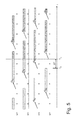
- Figure 5 is a schematic illustration of a fuel switch from the liquid fuel to the gaseous fuel that occurs when the injectors 14 are injecting; in particular, Figure 5 illustrates for each cylinder 2 the succession of the strokes (S - Exhaust, A - Intake, C - Compression, E - Expansion), the injection of the corresponding injector 14 (dotted bar) that injects the liquid fuel, the injection of the corresponding injector 15 (hatched bar) that injects the gaseous fuel, and the instant in which ignition sparking occurs (flash). Shown in Figure 5 is an instant T s in which the electronic unit 16 sends to the switching device 17 a switching command for electrically disconnecting the injectors 14 and hence electrically connecting the injectors 15.
- FIG. 5 shown in Figure 5 is an instant T c in which the switching device 17 actually carries out switching (starting from the instant T c the injectors 14 are all switched off and the injectors 15 are switched on; hence, injection of the liquid fuel terminates, and injection of the gaseous fuel starts).
- the instant T c is separated from the instant T s by a switching time delay ⁇ T, which is mostly due to the mechanical inertias of the electromechanical relays 18 and 19 of the switching device 17.
- control unit 16 determines in a known way an amount M air of air (supporter of combustion) that will be taken in into the cylinder 2 during the subsequent intake cycle.
- the control unit 16 can vary said amount M air of air taken in by acting on the throttle valve 10 and/or on the control of the intake valves 6 (if present) as a function of an r.p.m. target and/or of a torque target.
- control unit 16 determines an amount M1 fuel-fuel- ⁇ of the first fuel to be injected (i.e., the liquid fuel) as a function of the amount M air of supporter of combustion taken in and of the desired air/fuel ratio ⁇ 1 for the first fuel.
- the desired air/fuel ratio ⁇ 1 for the first fuel is calculated by multiplying a stoichiometric air/fuel ratio ⁇ stech (equal to 14.56 for petrol, and between 13.6 and 17.2 for methane, according to the characteristics of the methane) by a corrective coefficient K ⁇ that depends on whether engine control requires a lean combustion (K ⁇ higher than 1), a stoichiometric combustion (K ⁇ higher than 1), or else a rich combustion (K ⁇ lower than 1).
- the control unit 16 determines in a known way an injection time T1 inj as a function of the amount M1 fuel-o of the first fuel to be injected (namely, the injection time T1 inj is such that, if the injector 14 is opened for the injection time T1 inj , then it injects an amount of fuel equal to the amount M1 fuel-o of the first fuel to be injected).
- control unit 16 drives the corresponding injector 14 for activating the corresponding injector 14 for the injection time T1 inj (i.e., for keeping the corresponding injector 14 open for a time interval having a duration equal to the injection time T1 inj ).
- the control unit 16 carries out fuel switching by disconnecting electrically the injectors 14 from the control unit 16 (which is common for all the injectors 14 and 15) and connecting electrically the injectors 15 to the control unit 16.
- some injectors 14 are off (i.e., closed, de-activated) in so far as they are electrically disconnected from the control unit 16 and, at the same instant, the corresponding injectors 15 are on (i.e., open, activated) in so far as they are electrically connected to the control unit 16.
- the control unit 16 determines for each injector 14 that at the moment of fuel switching is active the amount M1 fuel-A of the first fuel that has been actually injected by the injector 14 itself until fuel switching, i.e., up to the instant T c (said determination is made knowing the time interval T1 inj-A during which the injector 14 has remained open up to fuel switching and knowing the characteristic of injection of the injector 14).
- the control unit 16 determines for each injector 14 that at the moment of fuel switching is active an amount M2 fuel-o of the second fuel to be injected (i.e., of the gaseous fuel) as a function of the amount M air of supporter of combustion taken in, of the amount M1 fuel-A of the first fuel that has been actually injected, of the desired air/fuel ratio ⁇ 1 for the first fuel, and of the desired air/fuel ratio ⁇ 2 for the second fuel (determined in the same way as has been described above for the desired air/fuel ratio ⁇ 1 for the first fuel).
- the desired air/fuel ratio ⁇ for each fuel is calculated by multiplying a stoichiometric air/fuel ratio ⁇ stech (equal to 14.56 for petrol, and comprised between 13.6 and 17.2 for methane, according to the characteristics of the methane) by a corrective coefficient K ⁇ that depends upon whether the engine control requires a lean combustion (K ⁇ higher than 1), a stoichiometric combustion (K ⁇ higher than 1), or else a rich combustion fat (K ⁇ lower than 1).
- the control unit 16 determines for each injector 15 that corresponds (i.e., that supplies one and the same cylinder 2) to an injector 14 that at the moment of fuel switching is active an injection time T2 inj as a function of the amount M2 fuel-o of the second fuel to be injected (i.e., the injection time T2 inj is such that, if the injector 15 is opened for the injection time T2 inj , then it injects an amount of fuel equal to the amount M2 fuel of the second fuel to be injected).
- control unit 16 drives, by means of the electrical connection to the control unit 16, each injector 15 corresponding to an injector 14 that at the moment of fuel switching is active for activating the injector 15 for the injection time T2 inj (i.e., for keeping the injector 15 open for a time interval having a duration equal to the injection time T2 inj ).
- the control unit 16 determines (by means of estimation algorithms or else by reading a value pre-loaded in a memory) the switching time delay ⁇ T and then determines for each injector 14 that is active at the moment of switching the amount M1 fuel-A of the first fuel that has been actually injected up to fuel switching as a function of the switching time delay ⁇ T.
- the control unit 16 knows the instant T s in which it sends to the switching device 17 the switching command and estimates the instant T c at which the switching device 17 actually carries out switching by adding the switching time delay ⁇ T to the instant T s . Then, knowing the instant T c at which the switching device 17 actually carries out switching, the control unit 16 can determine for how long each injector 14 that is active at the moment of switching has remained open and hence can determine precisely the amount M1 fuel-A of the first fuel that has actually been injected by the injector 14 itself up to fuel switching.
- the amount M2 fuel-o of the second fuel to be injected determined by applying the above equation guarantees that the "mixed" combustion of the two fuels (which in some cylinders 2 are injected together and thus burn together) will take place always with the desired air/fuel ratio ⁇ (in particular with the corrective coefficient K ⁇ constant irrespective of the fraction of gaseous or liquid fuel considered within the fractioned injection), and hence "mixed" combustion of the two fuels is prevented from causing an undesirable drop/peak of torque and/or an anomalous increase in emission of pollutant elements.
- any fuel switch performed in unfavourable conditions i.e., when at least some injectors 14 are active
- any fuel switch performed in unfavourable conditions i.e., when at least some injectors 14 are active
- an optimal way i.e., preventing any discontinuity in the generation of the torque and preventing peaks of emission of pollutant elements.
- the control unit 16 cyclically measures the pressure P rail of the gaseous fuel in the common channel 22 (i.e., immediately upstream of the injectors 15) by means of the pressure sensor 28, and, as a function of the pressure P rail of the gaseous fuel upstream of the injectors 15, decides, as explained in detail hereinafter, whether and when to carry out of automatic fuel switches (i.e., ones completely independent of the will of the driver) to prevent any irregular operation (i.e., undesirable drops or peaks in torque).
- automatic fuel switches i.e., ones completely independent of the will of the driver
- the control unit 16 determines a lower-limit threshold P rail-min and an upper-limit threshold P rail-max for the pressure P rail of the gaseous fuel upstream of the injectors 15; then, the control unit 16 cyclically compares the pressure P rail of the gaseous fuel upstream of the injectors 15 with the limit thresholds P rail-min and P rail-max and carries out automatically (i.e., in a way completely independent of the will of the driver) a fuel switch from the gaseous fuel to the liquid fuel when the pressure P rail of the gaseous fuel upstream of the injectors 15 exceeds one of the limit thresholds P rail-min and P rail-max (i.e., it drops below the lower-limit threshold P rail-min or else exceeds the upper-limit threshold P rail-max ).
- said pressure P rail of the gaseous fuel upstream of the injectors 15 is filtered with a lowpass filter to reduce the rate of variation (i.e., to eliminate sharp jumps that may also be due to errors of reading of the pressure sensor 28) and then the control unit 16 compares the filtered pressure P rail of the gaseous fuel upstream of the injectors 15 with the limit thresholds P rail-min and P rail-max .
- the control unit 16 compares the filtered pressure P rail of the gaseous fuel upstream of the injectors 15 with the limit thresholds P rail-min and P rail-max .
- the control unit 16 determines a minimum injection time T inj-min as a function of the constructional characteristics of the injectors 15 of the gaseous fuel (preferably the minimum injection time T inj-min is pre-stored in a memory of the control unit 16). In other words, an injector 14 always presents a minimum injection time T inj-min (supplied by the manufacturer of the injector 14) below which it is not advisable to drop (in so far as execution, repeatability, and/or precision of injection are no longer guaranteed).
- the control unit 16 cyclically determines the upper-limit threshold P rail-max as a function of the minimum injection time T inj-min and of the current amount of fuel injected (or else, alternatively, of a current amount of intake air, which is linked to the current amount of fuel injected by the desired air/fuel ratio).
- the upper-limit threshold P rail-max is equal to the pressure P rail of the gaseous fuel upstream of the injectors 15 for which, by opening (switching on/activating) an injector 14 for the minimum injection time T inj-min , there is injected exactly the current amount of fuel (i.e., below the upper-limit threshold P rail-max , to inject the current amount of fuel, it is necessary to open the injector 14 for an injection time longer than the minimum injection time T inj-min , whereas above the upper-limit threshold P rail-max , to inject the current amount of fuel, it is necessary to open the injector 14 for an injection time shorter than the minimum injection time T inj-min ).
- the upper-limit threshold P rail-max represents the maximum pressure P rail of the gaseous fuel upstream of the injectors 15 beyond which, to inject the current amount of fuel, it would be necessary (but obviously not possible/advisable) to open (switch on/activate) the injector 14 for an injection time shorter than the minimum injection time T inj-min .
- control unit 16 cyclically determines a maximum injection time T inj-max as a function of the current r.p.m.
- injection of the fuel for a given cycle of a cylinder 2 cannot take place at any one moment but must necessarily terminate (with a certain advance) by the end of the intake stroke in the case of indirect injection and (with a certain advance) by the end of the compression stroke in the case of direct injection. Otherwise, if these limits are not respected, part of the fuel injected is not burnt and is discharged unburnt together with the exhaust gases. It may be expedient also to impose a given arbitrary end-of-injection phase (i.e., one that is not necessarily identifiable with the end of an engine stroke) that is to be respected.
- control unit 16 cyclically determines a maximum injection time T inj-max , i.e., how long the maximum interval available for injecting the fuel lasts.
- the maximum interval available for injecting the fuel is substantially constant, but by varying the speed of rotation of the engine shaft 4 (i.e., by varying the r.p.m.), the maximum time interval available for injecting the fuel increases (lower r.p.m.) or decreases (higher r.p.m.).
- the control unit 16 cyclically determines the lower-limit threshold P rail-min as a function of the maximum injection time T inj-max and of the current amount of fuel injected (or else, alternatively, of a current amount of intake air, which is linked to the current amount of fuel injected by the desired air/fuel ratio).
- the lower-limit threshold P rail-min is equal to the pressure P rail of the gaseous fuel upstream of the injectors 15 for which, by opening (switching on/activating) an injector 14 for the maximum injection time T inj-max , exactly the current amount of fuel is injected (i.e., above the lower-limit threshold P rail-min , to inject the current amount of fuel, it is necessary to open the injector 14 for an injection time shorter than the maximum injection time T inj-max , whereas below the lower-limit threshold P rail-min , to inject the current amount of fuel, it is necessary to open the injector 14 for an injection time longer than the maximum injection time T inj-max ).
- the lower-limit threshold P rail-min represents the minimum pressure P rail of the gaseous fuel upstream of the injectors 15, below which, to inject the current amount of fuel, it would be necessary (but obviously not possible/advisable) to open (switch on/activate) the injector 14 for an injection time longer than the maximum injection time T inj-max .
- the current amount of fuel injected can be determined in various ways: generally, the current amount of fuel injected is equal to the amount of fuel that must be injected in the next injection, but alternatively the current amount of fuel injected can also be equal to the amount of fuel that has been injected in the last injection, or else can be equal to an average of the amounts of fuel injected during the last 3-10 injections (averaging prevents a single "peak" value from being taken into consideration, but just the trend is considered).
- the control unit 16 determines the first time derivative of the pressure P rail of the gaseous fuel upstream of the injectors 15 (as has been said previously, preferably the control unit 16 determines the first time derivative of the pressure P rail of the gaseous fuel upstream of the injectors 15 filtered with a lowpass filter) and then determines the limit thresholds P rail-min and P rail-max also as a function of the first time derivative of the pressure P rail of the gaseous fuel upstream of the injectors 15.
- the lower-limit threshold P rail-min is increased (i.e., rendered more stringent) when the first time derivative of the pressure P rail of the gaseous fuel upstream of the injectors 15 exceeds a pre-set negative slope (i.e., when the pressure P rail of the gaseous fuel upstream of the injectors 15 decreases very rapidly)
- the upper-limit threshold P rail-max is decreased (i.e., rendered more stringent) when the first time derivative of the pressure P rail of the gaseous fuel upstream of the injectors 15 exceeds a pre-set positive slope (i.e., when the pressure P rail of the gaseous fuel upstream of the injectors 15 increases very rapidly).
- the modification of the limit thresholds P rail-min and P rail-max also as a function of the first time derivative of the pressure P rail of the gaseous fuel upstream of the injectors 15 enables the control unit 16 to act faster when the pressure P rail of the gaseous fuel upstream of the injectors 15 presents a very fast change (i.e., a decrease or else an increase).
- the control unit 16 waits, after switching the fuel from the gaseous fuel to the liquid fuel, for a waiting time interval WT during which no fuel switch is performed (i.e., liquid fuel continues to be supplied). After the end of the waiting time interval WT, the control unit 16 cyclically verifies whether the pressure P rail of the gaseous fuel upstream of the injectors 15 is still beyond the limit threshold P rail-min or P rail-max that has determined the previous automatic fuel switch (i.e., whether the pressure P rail of the gaseous fuel upstream of the injectors 15 is still lower than the lower-limit threshold P rail-min or else is still higher than the upper-limit threshold P rail-max ).
- the control unit 16 automatically carries out a fuel switch from the liquid fuel to the gaseous fuel if, after the end of the waiting time interval WT, the pressure P rail of the gaseous fuel upstream of the injectors 15 is no longer beyond the limit threshold P rail-min or P rail-max that has determined the previous automatic fuel switch (i.e., if the pressure P rail of the gaseous fuel upstream of the injectors 15 has risen above the lower-limit threshold P rail-min or else has dropped again below the upper-limit threshold P rail-max ).
- Figures 6-8 show the plot in time of the pressure P rail of the gaseous fuel upstream of the injectors 15 in three different situations.
- the control unit 16 carries out a new automatic fuel switch from the liquid fuel to the gaseous fuel in so far as at the end of the waiting time interval WT (i.e., at the instant T 1 ) the pressure P rail of the gaseous fuel upstream of the injectors 15 is higher than the lower-limit threshold P rail-min .
- the control unit 16 carries out a new automatic fuel switch from the liquid fuel to the gaseous fuel in so far as at the end of the waiting time interval WT (i.e., at the instant T 3 ) the pressure P rail of the gaseous fuel upstream of the injectors 15 is lower than the upper-limit threshold P rail-max .
- the control unit 16 does not carry out a new automatic fuel switch from the liquid fuel to the gaseous fuel in so far as, at the end of the waiting time interval WT (i.e., at the instant T 5 ), the pressure P rail of the gaseous fuel upstream of the injectors 15 is still higher than the upper-limit threshold P rail-max .
- the control unit 16 carries out a new automatic fuel switch from the liquid fuel to the gaseous fuel at the instant T 6 , in which the pressure P rail of the gaseous fuel upstream of the injectors 15 drops below of the upper-limit threshold P rail-max (hence well beyond the waiting time interval WT from the instant T 4 in which automatic fuel switching from the gaseous fuel to the liquid fuel has been performed).
- the control unit 16 waits indefinitely (beyond the waiting time interval WT) for the pressure P rail of the fuel to drop back again below the upper-limit threshold P rail-max to carry out the opposite automatic fuel switching from liquid fuel to gaseous fuel.
- the control unit 16 does not wait indefinitely (beyond the waiting time interval WT) for the pressure P rail of the fuel to rise above the lower-limit threshold P rail-min to carry out the opposite automatic fuel switching from liquid fuel to gaseous fuel.
- control unit 16 disables, up to the next turning-off of the internal-combustion engine 1 or else up to the next refuelling with gaseous fuel, fuel switching from the liquid fuel to the gaseous fuel if, at the end of the waiting time interval WT, the pressure P rail of the gaseous fuel upstream of the injectors 15 is still lower than the lower-limit threshold P rail-min .
- control unit 16 measures a level of the gaseous fuel in the tank 21 and disables, if the pressure P rail of the gaseous fuel upstream of the injectors 15 has dropped below the lower-limit threshold P rail-min and up to the next turning-off of the internal-combustion engine 1 or else up to the next refuelling with gaseous fuel, fuel switching from the liquid fuel to the gaseous fuel as a function of the current hourly consumption of the gaseous fuel and as a function of the level of the gaseous fuel in the tank 21.
- automatic fuel switching from the gaseous fuel to the liquid fuel is performed immediately when the pressure P rail of the gaseous fuel upstream of the injectors 15 passes beyond one of the limit thresholds P rail-min or P rail-max (i.e., irrespective of the state of operation of the internal-combustion engine 1), whilst, to carry out the opposite automatic fuel switching from the liquid fuel to the gaseous fuel, it is necessary to wait for a cut-off phase, an idling phase, or else a stabilized-r.p.m. phase.
- the pressure P rail of the gaseous fuel upstream of the injectors 15 it is possible to wait for a stabilization of the pressure P rail of the gaseous fuel upstream of the injectors 15 (i.e., the pressure P rail of the gaseous fuel upstream of the injectors 15 must remain approximately constant, i.e., without jumps, for a certain time), in addition to verifying, as is obvious, that the pressure P rail of the gaseous fuel upstream of the injectors 15 is comprised between the lower-limit threshold P rail-min and the upper-limit threshold P rail-max .
- the control unit 16 increases, up to the next turning-off of the internal-combustion engine 1, the lower-limit threshold P rail-min and decreases the upper-limit threshold P rail-max by means of corresponding contributions of hysteresis whenever an automatic fuel switch from the gaseous fuel to the liquid fuel is performed.
- the control unit 16 can measure a level of the gaseous fuel in the tank 21 and then can determine the contributions of hysteresis as a function of the level of the gaseous fuel in the tank 21.
- the function of the contributions of hysteresis is to reduce the number of automatic fuel switches maintaining for a longer time supply of the liquid fuel instead of the gaseous fuel when the pressure P rail of the gaseous fuel upstream of the injectors 15 "oscillates" around a limit threshold P rail-min or P rail-max .
- the pressure P rail of the gaseous fuel upstream of the injectors 15 drops below the lower-limit threshold P rail-min when the tank 21 of the gaseous fuel is running out.
- the pressure P rail of the gaseous fuel upstream of the injectors 15 drops below the lower-limit threshold P rail-min when a very fast transient occurs in which the internal-combustion engine 1 rapidly passes from a situation of zero (or very low) torque, in which only a small amount of gaseous fuel is injected, to a situation of maximum (or very high) torque, in which a large amount of gaseous fuel is injected.
- the pressure regulator 25 for the gaseous fuel upstream of the injectors 15 may respond with a certain delay to the variation of the flowrate of the gaseous fuel on account of its mechanical inertias and may hence supply temporarily to the injectors 15 a flow of gaseous fuel that is too low (with a consequent even considerable decrease in the pressure P rail of the gaseous fuel upstream of the injectors 15 as compared to the nominal value).
- the pressure P rail of the gaseous fuel upstream of the injectors 15 rises above the upper-limit threshold P rail-max when a very fast transient occurs in which the internal-combustion engine 1 rapidly passes from a situation of maximum (or very high) torque, in which a large amount of gaseous fuel is injected, to a situation of zero (or very low) torque, in which only a small amount of gaseous fuel is injected.
- the pressure regulator 25 for the gaseous fuel upstream of the injectors 15 may respond with a certain delay to the variation of the flowrate of the gaseous fuel on account of its mechanical inertias and hence may supply temporarily to the injectors 15 a flowrate of gaseous fuel that is to high (with a consequent even considerable increase in the pressure P rail of the gaseous fuel upstream of the injectors 15 as compared to the nominal value). Said variations in the pressure P rail of the gaseous fuel upstream of the injectors 15 as compared to the nominal value are likely to bring about errors in injection of the gaseous fuel (i.e., deviations between the amount of gaseous fuel actually injected and the optimal amount of gaseous fuel).
- the method for controlling fuel injection described above is simple and economically advantageous to implement in an electronic control unit for a new-generation internal-combustion engine in so far as it uses measurements supplied by sensors that are normally present in modern internal-combustion engines (and hence does not call for any hardware modifications) and does not require either a high computational power or a high occupation of memory.
Description
- The present invention relates to a method for controlling fuel injection in a multifuel internal-combustion engine.
- The present invention finds advantageous application in a two-fuel internal-combustion engine, to which the present description will make explicit reference, without this applying any loss of generality.
- A two-fuel internal-combustion engine is able to function indifferently with two different types of fuel (typically petrol and LPG or petrol and methane). A modern two-fuel internal-combustion engine uses two different injector assemblies, each of which is able to inject a respective type of fuel.
- In the case of an after-market adaptation of the internal-combustion engine, two separate electronic control units are always used, each of which controls a respective injector assembly independently of the other; however, said solution proves costly in so far as it requires installation of two separate and independent electronic control units.
- In the case of an internal-combustion engine that has been designed to be of a two-fuel type, instead of using two separate and independent electronic control units, a single common electronic control unit is normally used, which can drive electrically both of the injector assemblies by means of a switching device that receives at input the electrical driving signals supplied by the common electronic control unit and supplies at output the electrical driving signals to one injector assembly at a time. For example, the switching device can comprise a plurality of electromechanical relays, each of which is designed to connect electrically and alternatively two injectors to one and the same output of the common electronic control unit.
- In a two-fuel internal-combustion engine, one of the main targets is to prevent irregular operations during which in the cylinders there is supplied too little fuel (creating an undesirable drop in torque) or else too much fuel (creating a peak in torque that is equally undesirable). One of the situations where irregular operation is more likely to occur is the step of transition from one fuel to the other. Irregular operation may also arise when the engine is supplied with a gaseous fuel and there occurs a very fast transient in which the engine passes rapidly from a situation of zero torque to a situation of maximum torque, or vice versa. In said passages, the pressure regulator for the gaseous fuel may respond with a certain delay to the variation of the flowrate of the gaseous fuel on account of its mechanical inertias and may hence supply to the injectors a flowrate of gaseous fuel that is too low (with a consequent even considerable decrease in the pressure of the gaseous fuel as compared to the nominal value) or else too high (with a consequent even considerable increase in the pressure of the gaseous fuel as compared to the nominal value). Said variations of the pressure of the gaseous fuel as compared to the nominal value easily bring about errors in injection of the gaseous fuel (i.e., deviations between the amount of gaseous fuel actually injected and the optimal amount of gaseous fuel).
- The patent application No.
DE10248228A1 describes a method for controlling fuel injection in a multifuel internal-combustion engine, wherein a request is received for fuel switching and fuel switching is performed following upon reception of the request for fuel switching. - The aim of the present invention is to provide a method for controlling fuel injection in a multifuel internal-combustion engine, said control method being free from the drawbacks described above and, in particular, being easy and economically advantageous to implement.
- According to the present invention a method for controlling fuel injection in a multifuel internal-combustion engine is provided according to what is claimed in the annexed claims.
- The present invention will now be described with reference to the annexed drawings, which illustrate a non-limiting example of embodiment thereof and in which:
-
Figure 1 is a schematic view of a two-fuel internal-combustion engine provided with a control unit that implements the method for controlling injection of fuel forming the subject of the present invention; -
Figure 2 is a schematic view of a single cylinder of the internal-combustion engine ofFigure 1 ; -
Figure 3 is a schematic view of a system for supply of a gaseous fuel of the internal-combustion engine ofFigure 1 ; -
Figure 4 is a graph that illustrates a temporal succession of steps for implementing fuel switching in the internal-combustion engine ofFigure 1 ; -
Figure 5 is a graph that illustrates the succession of injections and ignitions in the cylinders of the internal-combustion engine ofFigure 1 during a fuel switch; and -
Figures 6-8 are graphs that illustrate the evolution of a pressure of a gaseous fuel in a common channel in three different operating conditions. - In
Figure 1 , designated as a whole by thereference number 1 is a two-fuel internal-combustion engine, i.e., one that can be supplied with two different fuels and in particular a liquid fuel (typically petrol) and a gaseous fuel (for example, LPG or else methane). - The
engine 1 comprises fourcylinders 2 set in line; eachcylinder 2 houses arespective piston 3 mechanically connected by means of a connecting rod to anengine shaft 4 for transmitting to theengine shaft 4 itself the force generated by the combustion within thecylinder 2. According to what is illustrated inFigure 2 , eachcylinder 2 is connected to anintake manifold 5 via two intake valves 6 (only one of which is illustrated inFigure 2 ) and to anexhaust manifold 7 via two exhaust valves 8 (only one of which is illustrated inFigure 2 ). - The
intake manifold 5 receives fresh air (i.e., air coming from the external environment) through asupply duct 9 regulated by athrottle valve 10 and is connected to thecylinders 2 by means of respective intake ducts 11 (only one of which is illustrated inFigure 2 ), each of which is regulated by thecorresponding intake valves 6. Likewise, theexhaust manifold 7 is connected to thecylinders 2 by means of respective exhaust ducts 12 (only one of which is illustrated inFigure 2 ), each of which is regulated by thecorresponding exhaust valves 8. Departing from theexhaust manifold 7 is anoutlet pipe 13, which terminates with a silencer for emitting the gases produced by combustion into the atmosphere. - Each
cylinder 2 comprises a spark plug (not illustrated), which is set on the roof of thecylinder 2 and is cyclically driven for igniting the mixture at the end of the compression stroke (i.e., approximately at the TDC - top dead centre). According to the embodiment illustrated inFigure 2 , twoinjectors intake pipe 11 and in the proximity of thecorresponding intake valves 6; in particular, theinjector 14 injects the liquid fuel, and theinjector 15 injects the gaseous fuel. According to a different embodiment not illustrated, theinjectors cylinder 2. - An electronic control unit (ECU) 16 supervises operation of the internal-
combustion engine 1. According to what is illustrated inFigure 2 , thecontrol unit 16 is connected to theinjectors switching device 17 that enables selection of whichinjector assembly control unit 16 and thus receives from thecontrol unit 16 the electrical driving signals. Theswitching device 17 comprises a set of four relays 18 (only one of which is illustrated inFigure 2 ), each of which connects acorresponding injector 14 to an output of thecontrol unit 16, and a set of four relays 19 (only one of which is illustrated inFigure 2 ), each of which connects acorresponding injector 15 to an output of thecontrol unit 16. To supply the liquid fuel into thecylinders 2, thecontrol unit 16 drives therelays injectors 14 to its own outputs (and thus disconnect theinjectors 15 from its own outputs); likewise, to supply the gaseous fuel into thecylinders 2, thecontrol unit 16 drives therelays injectors 15 to its own outputs (and thus disconnect theinjectors 14 from its own outputs). Therelays relay 18 and thecorresponding relay 19 could be physically integrated in a single common container. - According to what is illustrated in
Figure 3 , thesystem 20 for supply of the gaseous fuel comprises atank 21 constituted by at least one gas cylinder, acommon channel 22 directly connected to which are theinjectors 15, and asupply duct 23 that connects thetank 21 to thecommon channel 22. Set along thesupply duct 23 is a shut-offsolenoid valve 24 and then apressure regulator 25 set downstream of the shut-off solenoid valve 24 (when the gaseous fuel is methane, thepressure regulator 25 only performs pressure reduction, whereas, when the gaseous fuel is LPG, thepressure regulator 25 carries out also gasification of the liquefied fuel). A branch of thesupply duct 23 opposite to the branch that leads to thecommon channel 22 terminates with afilling valve 26 that is used for filling thetank 21. Coupled to thepressure regulator 25 is apressure sensor 27, which detects the pressure of the fuel upstream of thepressure regulator 25, whereas coupled to thecommon channel 22 is apressure sensor 28 that detects the pressure Prail of the fuel within the common channel 22 (i.e., immediately upstream of theinjectors 15 for the gaseous fuel). - When the
control unit 16 receives from the driver the request for carrying out a switching of fuel (i.e., for passing from supply of the liquid fuel to supply of the gaseous fuel or vice versa), thecontrol unit 16 must decide at what instant to carry out switching (i.e., at what instant to drive the switching device 17). The purpose of thecontrol unit 16 is to carry out fuel switching preventing any irregular operation during which too much or too little fuel is supplied to thecylinders 2. - It may be readily appreciated that the ideal moment for carrying out a fuel switch is the cut-off phase, during which nothing is injected (since nothing is injected, it is evident that it is not possible to commit any type of error on the amount of fuel injected). However, the cut-off phase is not (always) so frequent (rather, when travelling on a motorway at an approximately constant speed, it may not occur for several dozens of minutes); hence, it is not possible to set the condition of carrying out fuel switching only during a cut-off phase in so far as it is not acceptable for a command issued by the driver to be executed after an excessive delay (normally the maximum delay allowed between the command issued by the driver and execution of fuel switching is a few seconds).
- If it is not possible to carry out fuel switching during a cut-off phase, then the other very favourable condition for carrying out fuel switching is the idling phase, i.e., when the r.p.m. of the
engine shaft 4 is constant and equal to the minimum r.p.m. (during idling fuel injections are very short and considerably separate from one another in so far as the torque to be generated has only the purpose of supporting rotation of the engine shaft 4). In fact, in an idling phase the actions to be carried out for engine control are absolutely foreseeable in a precise way and it is simple to identify a time window without any fuel injection in which to carry out fuel switching. - If it is not possible to carry out fuel switching during a cut-off phase or else during an idling phase, then the other quite favourable condition for carrying out fuel switching is a stabilized-r.p.m. phase, i.e., when the speed of rotation of the
engine shaft 4 and the engine load (i.e., the torque generated) are approximately constant. In fact, in a stabilized-r.p.m. phase the actions to be carried out for engine control are easily foreseeable in a precise way, and hence it is simpler to prevent errors being committed on the amount of fuel injected. - The worst moment in which to carry out fuel switching is an acceleration transient, during which the speed of rotation of the
engine shaft 4 increases (with discontinuities during gear change) and also the engine load presents variations. In fact, during a transient of acceleration the actions to be carried out for engine control are more difficult to foresee precisely, and hence it is more difficult to prevent errors on the amount of fuel injected. - According to what is illustrated in
Figure 4 , thecontrol unit 16 receives from the driver the request for carrying out a fuel switch at an instant T0 starting from which thecontrol unit 16 must carry out fuel switching. Immediately after the instant T0 thecontrol unit 16 verifies whether there exist the conditions for carrying out fuel switching (for example, it checks that the "new" fuel has not run out, or else that the temperature is sufficient for carrying out gasification of the "new" fuel in the pressure regulator 25). - Once the
control unit 16 has verified that there exist the conditions for carrying out fuel switching, then thecontrol unit 16 activates without any further delay supply of the "new" fuel to thecorresponding injectors control unit 16 opens the shut-off solenoid valve 24 (which is always closed for reasons of safety when the gaseous fuel is not used). Instead, if the "new" fuel is the liquid fuel, then thecontrol unit 16 switches on a fuel pump, which supplies the pressurized liquid fuel to the injectors 14 (when the liquid fuel is not used, the fuel pump is switched off for energy saving). To allow settling of the transients following upon the actions necessary to enable injection of the "new" fuel (i.e., to allow the "new" fuel to reach itsown injectors control unit 16 waits for a time interval A. The duration of the time interval A is normally comprised between 1 and 3 s and can vary, for example, as a function of the time that has elapsed from the last fuel switch for fuel switches to the liquid fuel (the longer the time that has elapsed since the last fuel switch, the longer the duration of the time interval A must be) or else as a function of the pressure of the gaseous fuel within thecommon channel 22 at the moment of start of fuel switching for fuel switches to gaseous fuel (the lower the pressure of the gaseous fuel within thecommon channel 22, the longer the duration of the time interval A must be). - Starting from an instant T1 (which is separated from the previous instant T0 by the time interval A), the
control unit 16 waits, for a time interval B, for a cut-off phase or else an idling phase to occur for carrying out fuel switching. In other words, starting from the instant T1 and for the time interval B, thecontrol unit 16 carries out fuel switching only if a cut-off phase or else an idling phase occurs. The duration of the time interval B is normally comprised between 2 s and 4 s and may vary, for example, as a function of the driving mode chosen by the driver (the time interval B may be longer in "economy" mode and shorter in "sport" mode). - Starting from an instant T2 (which is separated from the previous instant T1 by the time interval B), the
control unit 16 waits, for a time interval C, for a cut-off phase, or else an idling phase, or else a stabilized-r.p.m. phase to occur for carrying out fuel switching. In other words, starting from the instant T2 and for the time interval C, thecontrol unit 16 carries out fuel switching only if a cut-off phase, or else an idling phase, or else a stabilized-r.p.m. phase occurs. The duration of the time interval C is normally comprised between 2 s and 4 s may vary, for example, as a function of the driving mode chosen by the driver (the time interval C may be longer in "economy" mode and shorter in "sport" mode). - Finally, starting from an instant T3 (which is separated from the previous instant T2 by the time interval C), the
control unit 16 carries out without any further delay fuel switching irrespective of whether a cut-off phase, an idling phase, or else a stabilized-r.p.m. phase occurs. In other words, starting from the instant T3 thecontrol unit 16 carries out fuel switching in any case even though no cut-off phase, or idling phase, or stabilized-r.p.m. phase occurs. - According to a preferred embodiment, at the instant T1 the
control unit 16, before starting to consider execution of fuel switching, checks that the pressure of the "new" fuel immediately upstream of the correspondinginjectors - Thanks to the modalities described above, it is possible to ensure at the same time that fuel switching always occurs in the best conditions possible (namely, if possible, during a cut-off phase, during an idling phase, or else during a stabilized-r.p.m. phase) compatibly with the need to carry out fuel switching with a non-excessive delay with respect to the instant in which the driver imparts the command (request) for carrying out fuel switching.
- As has been said previously, it would be preferable to carry out fuel switching when the
injectors injectors -
Figure 5 is a schematic illustration of a fuel switch from the liquid fuel to the gaseous fuel that occurs when theinjectors 14 are injecting; in particular,Figure 5 illustrates for eachcylinder 2 the succession of the strokes (S - Exhaust, A - Intake, C - Compression, E - Expansion), the injection of the corresponding injector 14 (dotted bar) that injects the liquid fuel, the injection of the corresponding injector 15 (hatched bar) that injects the gaseous fuel, and the instant in which ignition sparking occurs (flash). Shown inFigure 5 is an instant Ts in which theelectronic unit 16 sends to the switching device 17 a switching command for electrically disconnecting theinjectors 14 and hence electrically connecting theinjectors 15. In addition, shown inFigure 5 is an instant Tc in which theswitching device 17 actually carries out switching (starting from the instant Tc theinjectors 14 are all switched off and theinjectors 15 are switched on; hence, injection of the liquid fuel terminates, and injection of the gaseous fuel starts). The instant Tc is separated from the instant Ts by a switching time delay ΔT, which is mostly due to the mechanical inertias of theelectromechanical relays switching device 17. - During normal control of the internal-
combustion engine 1, for eachcylinder 2 thecontrol unit 16 determines in a known way an amount Mair of air (supporter of combustion) that will be taken in into thecylinder 2 during the subsequent intake cycle. Thecontrol unit 16 can vary said amount Mair of air taken in by acting on thethrottle valve 10 and/or on the control of the intake valves 6 (if present) as a function of an r.p.m. target and/or of a torque target. - Once the amount Mair of air taken in has been determined, for each
cylinder 2 thecontrol unit 16 determines an amount M1fuel-fuel-ο of the first fuel to be injected (i.e., the liquid fuel) as a function of the amount Mair of supporter of combustion taken in and of the desired air/fuel ratio λ1 for the first fuel. The desired air/fuel ratio λ1 for the first fuel is calculated by multiplying a stoichiometric air/fuel ratio λstech (equal to 14.56 for petrol, and between 13.6 and 17.2 for methane, according to the characteristics of the methane) by a corrective coefficient Kλ that depends on whether engine control requires a lean combustion (Kλ higher than 1), a stoichiometric combustion (Kλ higher than 1), or else a rich combustion (Kλ lower than 1). - Next, for each
cylinder 2 thecontrol unit 16 determines in a known way an injection time T1inj as a function of the amount M1fuel-o of the first fuel to be injected (namely, the injection time T1inj is such that, if theinjector 14 is opened for the injection time T1inj, then it injects an amount of fuel equal to the amount M1fuel-o of the first fuel to be injected). - Finally, at the pre-set moment and for each
cylinder 2 thecontrol unit 16 drives the correspondinginjector 14 for activating the correspondinginjector 14 for the injection time T1inj (i.e., for keeping the correspondinginjector 14 open for a time interval having a duration equal to the injection time T1inj). - As illustrated in
Figure 5 , in somecylinders 2 of the internal-combustion engine 1, while the correspondinginjectors 14 are active (i.e., are open and are injecting the first fuel), thecontrol unit 16 carries out fuel switching by disconnecting electrically theinjectors 14 from the control unit 16 (which is common for all theinjectors 14 and 15) and connecting electrically theinjectors 15 to thecontrol unit 16. Hence, at the instant Tc someinjectors 14 are off (i.e., closed, de-activated) in so far as they are electrically disconnected from thecontrol unit 16 and, at the same instant, the correspondinginjectors 15 are on (i.e., open, activated) in so far as they are electrically connected to thecontrol unit 16. - At the moment of fuel switching (or with a slight advance) the
control unit 16 determines for eachinjector 14 that at the moment of fuel switching is active the amount M1fuel-A of the first fuel that has been actually injected by theinjector 14 itself until fuel switching, i.e., up to the instant Tc (said determination is made knowing the time interval T1inj-A during which theinjector 14 has remained open up to fuel switching and knowing the characteristic of injection of the injector 14). - Then, the
control unit 16 determines for eachinjector 14 that at the moment of fuel switching is active an amount M2fuel-o of the second fuel to be injected (i.e., of the gaseous fuel) as a function of the amount Mair of supporter of combustion taken in, of the amount M1fuel-A of the first fuel that has been actually injected, of the desired air/fuel ratio λ1 for the first fuel, and of the desired air/fuel ratio λ2 for the second fuel (determined in the same way as has been described above for the desired air/fuel ratio λ1 for the first fuel). In particular, the amount M2fuel-o of the second fuel to be injected is determined by applying the following equation:
- M2fuel-o amount of the second fuel to be injected;
- Mair amount of supporter of combustion taken in into the
cylinder 2 of the internal-combustion engine 1; - M1fuel-A amount of the first fuel that has been actually injected by the
injector 14 up to fuel switching; - λ1 desired air/fuel ratio for the first fuel; and
- λ2 desired air/fuel ratio for the second fuel.
- As mentioned previously, the desired air/fuel ratio λ for each fuel is calculated by multiplying a stoichiometric air/fuel ratio λstech (equal to 14.56 for petrol, and comprised between 13.6 and 17.2 for methane, according to the characteristics of the methane) by a corrective coefficient Kλ that depends upon whether the engine control requires a lean combustion (Kλ higher than 1), a stoichiometric combustion (Kλ higher than 1), or else a rich combustion fat (Kλ lower than 1).
- Next, the
control unit 16 determines for eachinjector 15 that corresponds (i.e., that supplies one and the same cylinder 2) to aninjector 14 that at the moment of fuel switching is active an injection time T2inj as a function of the amount M2fuel-o of the second fuel to be injected (i.e., the injection time T2inj is such that, if theinjector 15 is opened for the injection time T2inj, then it injects an amount of fuel equal to the amount M2fuel of the second fuel to be injected). - Finally, the
control unit 16 drives, by means of the electrical connection to thecontrol unit 16, eachinjector 15 corresponding to aninjector 14 that at the moment of fuel switching is active for activating theinjector 15 for the injection time T2inj (i.e., for keeping theinjector 15 open for a time interval having a duration equal to the injection time T2inj). - As mentioned previously, between an instant Ts in which a switching command is sent by the
control unit 16 to theswitching device 17 and an instant Tc in which theswitching device 17 actually carries out switching there elapses a switching time delay ΔT. According to a preferred embodiment, thecontrol unit 16 determines (by means of estimation algorithms or else by reading a value pre-loaded in a memory) the switching time delay ΔT and then determines for eachinjector 14 that is active at the moment of switching the amount M1fuel-A of the first fuel that has been actually injected up to fuel switching as a function of the switching time delay ΔT. In other words, thecontrol unit 16 knows the instant Ts in which it sends to theswitching device 17 the switching command and estimates the instant Tc at which theswitching device 17 actually carries out switching by adding the switching time delay ΔT to the instant Ts. Then, knowing the instant Tc at which theswitching device 17 actually carries out switching, thecontrol unit 16 can determine for how long eachinjector 14 that is active at the moment of switching has remained open and hence can determine precisely the amount M1fuel-A of the first fuel that has actually been injected by theinjector 14 itself up to fuel switching. - The amount M2fuel-o of the second fuel to be injected determined by applying the above equation guarantees that the "mixed" combustion of the two fuels (which in some
cylinders 2 are injected together and thus burn together) will take place always with the desired air/fuel ratio λ (in particular with the corrective coefficient Kλ constant irrespective of the fraction of gaseous or liquid fuel considered within the fractioned injection), and hence "mixed" combustion of the two fuels is prevented from causing an undesirable drop/peak of torque and/or an anomalous increase in emission of pollutant elements. In this way, any fuel switch performed in unfavourable conditions (i.e., when at least someinjectors 14 are active) in any case occurs in an optimal way, i.e., preventing any discontinuity in the generation of the torque and preventing peaks of emission of pollutant elements. - When the internal-
combustion engine 1 is supplied with the gaseous fuel that is injected through theinjectors 15, thecontrol unit 16 cyclically measures the pressure Prail of the gaseous fuel in the common channel 22 (i.e., immediately upstream of the injectors 15) by means of thepressure sensor 28, and, as a function of the pressure Prail of the gaseous fuel upstream of theinjectors 15, decides, as explained in detail hereinafter, whether and when to carry out of automatic fuel switches (i.e., ones completely independent of the will of the driver) to prevent any irregular operation (i.e., undesirable drops or peaks in torque). - According to a preferred embodiment, the
control unit 16 determines a lower-limit threshold Prail-min and an upper-limit threshold Prail-max for the pressure Prail of the gaseous fuel upstream of theinjectors 15; then, thecontrol unit 16 cyclically compares the pressure Prail of the gaseous fuel upstream of theinjectors 15 with the limit thresholds Prail-min and Prail-max and carries out automatically (i.e., in a way completely independent of the will of the driver) a fuel switch from the gaseous fuel to the liquid fuel when the pressure Prail of the gaseous fuel upstream of theinjectors 15 exceeds one of the limit thresholds Prail-min and Prail-max (i.e., it drops below the lower-limit threshold Prail-min or else exceeds the upper-limit threshold Prail-max). - Preferably, before comparing the pressure Prail of the gaseous fuel upstream of the
injectors 15 with the limit thresholds Prail-min and Prail-max, said pressure Prail of the gaseous fuel upstream of theinjectors 15 is filtered with a lowpass filter to reduce the rate of variation (i.e., to eliminate sharp jumps that may also be due to errors of reading of the pressure sensor 28) and then thecontrol unit 16 compares the filtered pressure Prail of the gaseous fuel upstream of theinjectors 15 with the limit thresholds Prail-min and Prail-max. In this way, in the comparison with the limit thresholds Prail-min and Prail-max there is considered only the actual evolution of the pressure Prail of the gaseous fuel upstream of theinjectors 15, and not impulsive "irregularities". - The
control unit 16 determines a minimum injection time Tinj-min as a function of the constructional characteristics of theinjectors 15 of the gaseous fuel (preferably the minimum injection time Tinj-min is pre-stored in a memory of the control unit 16). In other words, aninjector 14 always presents a minimum injection time Tinj-min (supplied by the manufacturer of the injector 14) below which it is not advisable to drop (in so far as execution, repeatability, and/or precision of injection are no longer guaranteed). - The
control unit 16 cyclically determines the upper-limit threshold Prail-max as a function of the minimum injection time Tinj-min and of the current amount of fuel injected (or else, alternatively, of a current amount of intake air, which is linked to the current amount of fuel injected by the desired air/fuel ratio). In other words, the upper-limit threshold Prail-max is equal to the pressure Prail of the gaseous fuel upstream of theinjectors 15 for which, by opening (switching on/activating) aninjector 14 for the minimum injection time Tinj-min, there is injected exactly the current amount of fuel (i.e., below the upper-limit threshold Prail-max, to inject the current amount of fuel, it is necessary to open theinjector 14 for an injection time longer than the minimum injection time Tinj-min, whereas above the upper-limit threshold Prail-max, to inject the current amount of fuel, it is necessary to open theinjector 14 for an injection time shorter than the minimum injection time Tinj-min). In other words, the upper-limit threshold Prail-max represents the maximum pressure Prail of the gaseous fuel upstream of theinjectors 15 beyond which, to inject the current amount of fuel, it would be necessary (but obviously not possible/advisable) to open (switch on/activate) theinjector 14 for an injection time shorter than the minimum injection time Tinj-min. - Moreover, the
control unit 16 cyclically determines a maximum injection time Tinj-max as a function of the current r.p.m. In other words, injection of the fuel for a given cycle of acylinder 2 cannot take place at any one moment but must necessarily terminate (with a certain advance) by the end of the intake stroke in the case of indirect injection and (with a certain advance) by the end of the compression stroke in the case of direct injection. Otherwise, if these limits are not respected, part of the fuel injected is not burnt and is discharged unburnt together with the exhaust gases. It may be expedient also to impose a given arbitrary end-of-injection phase (i.e., one that is not necessarily identifiable with the end of an engine stroke) that is to be respected. Hence, on the basis of the current r.p.m. (which determines the time duration of the cycles of thecylinders 2, i.e., how long intake, compression, expansion, and exhaust last) thecontrol unit 16 cyclically determines a maximum injection time Tinj-max, i.e., how long the maximum interval available for injecting the fuel lasts. It should be noted that in terms of engine degrees (i.e., of angular space swept by the engine shaft 4) the maximum interval available for injecting the fuel is substantially constant, but by varying the speed of rotation of the engine shaft 4 (i.e., by varying the r.p.m.), the maximum time interval available for injecting the fuel increases (lower r.p.m.) or decreases (higher r.p.m.). - The
control unit 16 cyclically determines the lower-limit threshold Prail-min as a function of the maximum injection time Tinj-max and of the current amount of fuel injected (or else, alternatively, of a current amount of intake air, which is linked to the current amount of fuel injected by the desired air/fuel ratio). In other words, the lower-limit threshold Prail-min is equal to the pressure Prail of the gaseous fuel upstream of theinjectors 15 for which, by opening (switching on/activating) aninjector 14 for the maximum injection time Tinj-max, exactly the current amount of fuel is injected (i.e., above the lower-limit threshold Prail-min, to inject the current amount of fuel, it is necessary to open theinjector 14 for an injection time shorter than the maximum injection time Tinj-max, whereas below the lower-limit threshold Prail-min, to inject the current amount of fuel, it is necessary to open theinjector 14 for an injection time longer than the maximum injection time Tinj-max). In other words, the lower-limit threshold Prail-min represents the minimum pressure Prail of the gaseous fuel upstream of theinjectors 15, below which, to inject the current amount of fuel, it would be necessary (but obviously not possible/advisable) to open (switch on/activate) theinjector 14 for an injection time longer than the maximum injection time Tinj-max. - The current amount of fuel injected can be determined in various ways: generally, the current amount of fuel injected is equal to the amount of fuel that must be injected in the next injection, but alternatively the current amount of fuel injected can also be equal to the amount of fuel that has been injected in the last injection, or else can be equal to an average of the amounts of fuel injected during the last 3-10 injections (averaging prevents a single "peak" value from being taken into consideration, but just the trend is considered).
- According to a preferred embodiment, the
control unit 16 determines the first time derivative of the pressure Prail of the gaseous fuel upstream of the injectors 15 (as has been said previously, preferably thecontrol unit 16 determines the first time derivative of the pressure Prail of the gaseous fuel upstream of theinjectors 15 filtered with a lowpass filter) and then determines the limit thresholds Prail-min and Prail-max also as a function of the first time derivative of the pressure Prail of the gaseous fuel upstream of theinjectors 15. In particular, the lower-limit threshold Prail-min is increased (i.e., rendered more stringent) when the first time derivative of the pressure Prail of the gaseous fuel upstream of theinjectors 15 exceeds a pre-set negative slope (i.e., when the pressure Prail of the gaseous fuel upstream of theinjectors 15 decreases very rapidly), and the upper-limit threshold Prail-max is decreased (i.e., rendered more stringent) when the first time derivative of the pressure Prail of the gaseous fuel upstream of theinjectors 15 exceeds a pre-set positive slope (i.e., when the pressure Prail of the gaseous fuel upstream of theinjectors 15 increases very rapidly). The modification of the limit thresholds Prail-min and Prail-max also as a function of the first time derivative of the pressure Prail of the gaseous fuel upstream of theinjectors 15 enables thecontrol unit 16 to act faster when the pressure Prail of the gaseous fuel upstream of theinjectors 15 presents a very fast change (i.e., a decrease or else an increase). - According to a preferred embodiment, the
control unit 16 waits, after switching the fuel from the gaseous fuel to the liquid fuel, for a waiting time interval WT during which no fuel switch is performed (i.e., liquid fuel continues to be supplied). After the end of the waiting time interval WT, thecontrol unit 16 cyclically verifies whether the pressure Prail of the gaseous fuel upstream of theinjectors 15 is still beyond the limit threshold Prail-min or Prail-max that has determined the previous automatic fuel switch (i.e., whether the pressure Prail of the gaseous fuel upstream of theinjectors 15 is still lower than the lower-limit threshold Prail-min or else is still higher than the upper-limit threshold Prail-max). Hence, thecontrol unit 16 automatically carries out a fuel switch from the liquid fuel to the gaseous fuel if, after the end of the waiting time interval WT, the pressure Prail of the gaseous fuel upstream of theinjectors 15 is no longer beyond the limit threshold Prail-min or Prail-max that has determined the previous automatic fuel switch (i.e., if the pressure Prail of the gaseous fuel upstream of theinjectors 15 has risen above the lower-limit threshold Prail-min or else has dropped again below the upper-limit threshold Prail-max). - What has been described above is illustrated schematically in
Figures 6-8 , which show the plot in time of the pressure Prail of the gaseous fuel upstream of theinjectors 15 in three different situations. - In
Figure 6 , at the instant T0, the pressure Prail of the gaseous fuel upstream of theinjectors 15 drops below the lower-limit threshold Prail-min and hence at the instant T0 thecontrol unit 16 carries out an automatic fuel switch from the gaseous fuel to the liquid fuel. After the instant T0, the pressure Prail of the gaseous fuel upstream of theinjectors 15 starts to rise again, and hence at the instant T1 (i.e., after waiting for the waiting time interval WT from the instant T0) thecontrol unit 16 carries out a new automatic fuel switch from the liquid fuel to the gaseous fuel in so far as at the end of the waiting time interval WT (i.e., at the instant T1) the pressure Prail of the gaseous fuel upstream of theinjectors 15 is higher than the lower-limit threshold Prail-min. - In
Figure 7 , at the instant T2, the pressure Prail of the gaseous fuel upstream of theinjectors 15 exceeds the upper-limit threshold Prail-max, and hence, at the instant T2, thecontrol unit 16 carries out an automatic fuel switch from the gaseous fuel to the liquid fuel. After the instant T2, the pressure Prail of the gaseous fuel upstream of theinjectors 15 starts to drop again, and hence, at the instant T3 (i.e., after waiting for the waiting time interval WT from the instant T2), thecontrol unit 16 carries out a new automatic fuel switch from the liquid fuel to the gaseous fuel in so far as at the end of the waiting time interval WT (i.e., at the instant T3) the pressure Prail of the gaseous fuel upstream of theinjectors 15 is lower than the upper-limit threshold Prail-max. - In
Figure 8 , at the instant T4 the pressure Prail of the gaseous fuel upstream of theinjectors 15 exceeds the upper-limit threshold Prail-max, and hence at the instant T4 thecontrol unit 16 carries out an automatic fuel switch from the gaseous fuel to the liquid fuel. After the instant T4 the pressure Prail of the gaseous fuel upstream of theinjectors 15 starts to drop again but in quite a slow way, and hence at the instant T5 (i.e., after waiting for the waiting time interval WT from the instant T4) thecontrol unit 16 does not carry out a new automatic fuel switch from the liquid fuel to the gaseous fuel in so far as, at the end of the waiting time interval WT (i.e., at the instant T5), the pressure Prail of the gaseous fuel upstream of theinjectors 15 is still higher than the upper-limit threshold Prail-max. Thecontrol unit 16 carries out a new automatic fuel switch from the liquid fuel to the gaseous fuel at the instant T6, in which the pressure Prail of the gaseous fuel upstream of theinjectors 15 drops below of the upper-limit threshold Prail-max (hence well beyond the waiting time interval WT from the instant T4 in which automatic fuel switching from the gaseous fuel to the liquid fuel has been performed). - According to a preferred embodiment, after an automatic fuel switch due to the fact that the pressure Prail of the fuel was higher than the upper-limit threshold Prail-max, the
control unit 16 waits indefinitely (beyond the waiting time interval WT) for the pressure Prail of the fuel to drop back again below the upper-limit threshold Prail-max to carry out the opposite automatic fuel switching from liquid fuel to gaseous fuel. Instead, after an automatic fuel switch due to the fact that the pressure Prail of the fuel was lower than the lower-limit threshold Prail-min, thecontrol unit 16 does not wait indefinitely (beyond the waiting time interval WT) for the pressure Prail of the fuel to rise above the lower-limit threshold Prail-min to carry out the opposite automatic fuel switching from liquid fuel to gaseous fuel. Instead, thecontrol unit 16 disables, up to the next turning-off of the internal-combustion engine 1 or else up to the next refuelling with gaseous fuel, fuel switching from the liquid fuel to the gaseous fuel if, at the end of the waiting time interval WT, the pressure Prail of the gaseous fuel upstream of theinjectors 15 is still lower than the lower-limit threshold Prail-min. Alternatively, thecontrol unit 16 measures a level of the gaseous fuel in thetank 21 and disables, if the pressure Prail of the gaseous fuel upstream of theinjectors 15 has dropped below the lower-limit threshold Prail-min and up to the next turning-off of the internal-combustion engine 1 or else up to the next refuelling with gaseous fuel, fuel switching from the liquid fuel to the gaseous fuel as a function of the current hourly consumption of the gaseous fuel and as a function of the level of the gaseous fuel in thetank 21. - According to a preferred embodiment, automatic fuel switching from the gaseous fuel to the liquid fuel is performed immediately when the pressure Prail of the gaseous fuel upstream of the
injectors 15 passes beyond one of the limit thresholds Prail-min or Prail-max (i.e., irrespective of the state of operation of the internal-combustion engine 1), whilst, to carry out the opposite automatic fuel switching from the liquid fuel to the gaseous fuel, it is necessary to wait for a cut-off phase, an idling phase, or else a stabilized-r.p.m. phase. Alternatively or else in addition, to carry out the opposite automatic fuel switching from the liquid fuel to the gaseous fuel, it is possible to wait for a stabilization of the pressure Prail of the gaseous fuel upstream of the injectors 15 (i.e., the pressure Prail of the gaseous fuel upstream of theinjectors 15 must remain approximately constant, i.e., without jumps, for a certain time), in addition to verifying, as is obvious, that the pressure Prail of the gaseous fuel upstream of theinjectors 15 is comprised between the lower-limit threshold Prail-min and the upper-limit threshold Prail-max. - According to a preferred embodiment, the
control unit 16 increases, up to the next turning-off of the internal-combustion engine 1, the lower-limit threshold Prail-min and decreases the upper-limit threshold Prail-max by means of corresponding contributions of hysteresis whenever an automatic fuel switch from the gaseous fuel to the liquid fuel is performed. In particular, thecontrol unit 16 can measure a level of the gaseous fuel in thetank 21 and then can determine the contributions of hysteresis as a function of the level of the gaseous fuel in thetank 21. The function of the contributions of hysteresis is to reduce the number of automatic fuel switches maintaining for a longer time supply of the liquid fuel instead of the gaseous fuel when the pressure Prail of the gaseous fuel upstream of theinjectors 15 "oscillates" around a limit threshold Prail-min or Prail-max. - The pressure Prail of the gaseous fuel upstream of the
injectors 15 drops below the lower-limit threshold Prail-min when thetank 21 of the gaseous fuel is running out. Alternatively, the pressure Prail of the gaseous fuel upstream of theinjectors 15 drops below the lower-limit threshold Prail-min when a very fast transient occurs in which the internal-combustion engine 1 rapidly passes from a situation of zero (or very low) torque, in which only a small amount of gaseous fuel is injected, to a situation of maximum (or very high) torque, in which a large amount of gaseous fuel is injected. In this situation, thepressure regulator 25 for the gaseous fuel upstream of theinjectors 15 may respond with a certain delay to the variation of the flowrate of the gaseous fuel on account of its mechanical inertias and may hence supply temporarily to the injectors 15 a flow of gaseous fuel that is too low (with a consequent even considerable decrease in the pressure Prail of the gaseous fuel upstream of theinjectors 15 as compared to the nominal value). - The pressure Prail of the gaseous fuel upstream of the
injectors 15 rises above the upper-limit threshold Prail-max when a very fast transient occurs in which the internal-combustion engine 1 rapidly passes from a situation of maximum (or very high) torque, in which a large amount of gaseous fuel is injected, to a situation of zero (or very low) torque, in which only a small amount of gaseous fuel is injected. In this situation, thepressure regulator 25 for the gaseous fuel upstream of theinjectors 15 may respond with a certain delay to the variation of the flowrate of the gaseous fuel on account of its mechanical inertias and hence may supply temporarily to the injectors 15 a flowrate of gaseous fuel that is to high (with a consequent even considerable increase in the pressure Prail of the gaseous fuel upstream of theinjectors 15 as compared to the nominal value). Said variations in the pressure Prail of the gaseous fuel upstream of theinjectors 15 as compared to the nominal value are likely to bring about errors in injection of the gaseous fuel (i.e., deviations between the amount of gaseous fuel actually injected and the optimal amount of gaseous fuel). - Without the automatic fuel switching from the liquid fuel to the gaseous fuel described above, when the pressure Prail of the gaseous fuel upstream of the
injectors 15 passes beyond the limit threshold Prail-min or Prail-max for the reasons described above, there would occur an undesirable irregular operation of the internal-combustion engine 1, during which in thecylinders 2 too little fuel is supplied (creating an undesirable drop in torque) or else too much fuel is supplied (creating a peak in torque that is equally undesirable). Instead, thanks to the automatic fuel switching from the liquid fuel to the gaseous fuel described above, when the pressure Prail of the gaseous fuel upstream of theinjectors 15 passes beyond the limit threshold Prail-min or Prail-max for the reasons described above, no irregular operation of the internal-combustion engine 1 occurs. - It should be noted that the method for controlling fuel injection described above is simple and economically advantageous to implement in an electronic control unit for a new-generation internal-combustion engine in so far as it uses measurements supplied by sensors that are normally present in modern internal-combustion engines (and hence does not call for any hardware modifications) and does not require either a high computational power or a high occupation of memory.
Claims (11)
- A method for controlling fuel injection in a multifuel internal-combustion engine (1); the control method comprises the steps of:receiving a request for fuel switching at a first instant (T0); andcarrying out fuel switching following upon reception of the request for fuel switching;the control method is characterized in that it comprises the further steps of:waiting, starting from the first instant (T0), for a first time interval (A) during which fuel switching is never performed;carrying out, starting from a second instant (T1), which is separated from the previous first instant (T0) by the first time interval (A), and for a second time interval (B), fuel switching only if a cut-off phase, or else an idling phase occurs;carrying out, starting from a third instant (T2), which is separated from the preceding second instant (T1) by the second time interval (B) and for a third time interval (C), fuel switching only if a cut-off phase, an idling phase, or else a stabilized-r.p.m. phase occurs; andcarrying out, starting from a fourth instant (T3), which is separated from the previous third instant (T2) by the third time interval (C), fuel switching in any condition.
- The control method according to Claim 1, and comprising the further step of verifying, immediately after the first instant (T0), whether there exist the conditions for carrying out fuel switching.
- The control method according to Claim 2, and comprising the further step of activating supply of the "new" fuel to the corresponding injectors (14; 15) after the existence of the conditions for carrying out fuel switching has been verified.
- The control method according to Claim 3, wherein supply of the "new" fuel is activated by opening a shut-off solenoid valve (24) if the "new" fuel is a gaseous fuel, or else supply of the "new" fuel is activated by switching on a fuel pump if the "new" fuel is a liquid fuel.
- The control method according to any one of Claims 1 to 4, and comprising the further step of checking, at the second instant (T1) and prior to starting to consider execution of fuel switching, that the pressure of the "new" fuel at the corresponding injectors (14; 15) is adequate.
- The control method according to any one of Claims 1 to 5 and comprising the further steps of:varying, in a fuel switching to a liquid fuel, the duration of the first time interval (A) as a function of the time that has elapsed from the last fuel switching in such a way that the longer the time that has elapsed from the last fuel switching, the greater the duration of the first time interval (A); andvarying, in a fuel switching to a gaseous fuel, the duration of the first time interval (A) as a function of a pressure of the gaseous fuel within a common channel (22) at the moment of start of fuel switching in such a way that the lower the pressure of the gaseous fuel within the common channel (22), the greater the duration of the first time interval (A).
- The control method according to any one of Claims 1 to 6 and comprising the further steps of:determining an amount (Mair) of air taken in into a cylinder (2) of the internal-combustion engine (1);determining an amount (M1fuel-o) of a first fuel to be injected as a function of the amount (Mair) of air taken in and of the desired air/fuel ratio (λ1) for the first fuel;determining a first injection time (T1inj) as a function of the amount (M1fuel-o) of the first fuel to be injected;driving, by means of an electrical connection to a common control unit (16), a first injector (14; 15) for activating the first injector (14; 15) for the first injection time (T1inj); andcarrying out, whilst the first injector (14; 15) is active, a fuel switch by electrically disconnecting the first injector (14; 15) from the common control unit (16) and connecting electrically a second injector (15; 14) to the common control unit (16).
- The control method according to Claim 7 and comprising the further steps of:determining the amount (M1fuel-A) of the first fuel that has been actually injected by the first injector (14; 15) up to fuel switching;determining an amount (M2fuel-o) of a second fuel to be injected as a function of the amount (Mair) of air taken in, of the amount (M1fuel-A) of the first fuel that has been actually injected, of the desired air/fuel ratio (λ1) for the first fuel, and of the desired air/fuel ratio (λ2) for the second fuel;determining a second injection time (T2inj) as a function of the amount (M2fuel-o) of the second fuel to be injected; anddriving, by means of the electrical connection to the common control unit (16), the second injector (15; 14) for activating the second injector (15; 14) for the second injection time (T2inj).
- The control method according to Claim 8, wherein the amount (M2fuel-o) of the second fuel to be injected is determined by applying the following equation
 M2fuel-o amount of the second fuel to be injected;Mair amount of air taken in into the cylinder (2) of the internal-combustion engine (1);M1fuel-A amount of the first fuel that has been actually injected by the first injector (14; 15) up to fuel switching;λ1 desired air/fuel ratio for the first fuel; andλ2 desired air/fuel ratio for the second fuel.
 - The control method according to Claim 8 or Claim 9, wherein the desired air/fuel ratio (λ1; λ2) for a fuel is calculated by multiplying a stoichiometric air/fuel ratio (Astech) by a corrective coefficient (Kλ).
- The control method according to Claim 8, Claim 9 or Claim 10 and comprising the further steps of:determining a time delay (ΔT) of switching that elapses between a first instant (Ts) where a command for fuel switching is sent to a switching device (17) that electrically connects alternatively the two injectors (14, 15) to the common control unit (16) and a second instant (Tc) in which the switching device (17) actually carries out switching;determining a time interval (T1inj-A) during which the first injector (14; 15) has remained open up to fuel switching as a function of the switching time delay (ΔT); anddetermining the amount (M1fuel-A) of the first fuel that has been actually injected by the first injector (14; 15) up to fuel switching as a function of the time interval (T1inj-A) during which the first injector (14; 15) has remained open up to fuel switching.
Applications Claiming Priority (1)
| Application Number | Priority Date | Filing Date | Title |
|---|---|---|---|
| IT000290A ITBO20110290A1 (en) | 2011-05-23 | 2011-05-23 | METHOD OF CHECKING FUEL INJECTION IN A POLI-FUEL INTERNAL COMBUSTION ENGINE IN CASE OF FUEL SWITCHING REQUEST |
Publications (3)
| Publication Number | Publication Date |
|---|---|
| EP2527623A2 EP2527623A2 (en) | 2012-11-28 |
| EP2527623A3 EP2527623A3 (en) | 2013-08-14 |
| EP2527623B1 true EP2527623B1 (en) | 2015-07-29 |
Family
ID=44653391
Family Applications (1)
| Application Number | Title | Priority Date | Filing Date |
|---|---|---|---|
| EP12169094.5A Active EP2527623B1 (en) | 2011-05-23 | 2012-05-23 | Method for controlling fuel injection in a multifuel internal-combustion engine in the event of a request for fuel switching |
Country Status (2)
| Country | Link |
|---|---|
| EP (1) | EP2527623B1 (en) |
| IT (1) | ITBO20110290A1 (en) |
Cited By (1)
| Publication number | Priority date | Publication date | Assignee | Title |
|---|---|---|---|---|
| EP3384146B1 (en) * | 2015-11-30 | 2022-07-20 | Finn Associates (Businesscare) Limited | A multi-fuel engine and method of controlling the same |
Families Citing this family (1)
| Publication number | Priority date | Publication date | Assignee | Title |
|---|---|---|---|---|
| CN111396207B (en) * | 2020-03-31 | 2022-07-15 | 潍柴动力股份有限公司 | Engine injection control method and device |
Family Cites Families (4)
| Publication number | Priority date | Publication date | Assignee | Title |
|---|---|---|---|---|
| JPS63230933A (en) * | 1987-03-18 | 1988-09-27 | Toyota Motor Corp | Fuel switching method and device for dual fuel engine |
| DE10146063B4 (en) * | 2001-09-14 | 2013-08-08 | Iav Gmbh Ingenieurgesellschaft Auto Und Verkehr | A mode change method for internal combustion engines to be operated with a first liquid fuel or another second fuel |
| JP2003120352A (en) * | 2001-10-16 | 2003-04-23 | Aisan Ind Co Ltd | Fuel switching method and device for engine |
| DE102007030798A1 (en) * | 2007-07-03 | 2009-01-08 | Robert Bosch Gmbh | Method for operating combustion engine with multiple fuel types, involves calculating quantity of fuel for upstream fuel type, and change of fuel type is made occasionally |
-
2011
- 2011-05-23 IT IT000290A patent/ITBO20110290A1/en unknown
-
2012
- 2012-05-23 EP EP12169094.5A patent/EP2527623B1/en active Active
Cited By (1)
| Publication number | Priority date | Publication date | Assignee | Title |
|---|---|---|---|---|
| EP3384146B1 (en) * | 2015-11-30 | 2022-07-20 | Finn Associates (Businesscare) Limited | A multi-fuel engine and method of controlling the same |
Also Published As
| Publication number | Publication date |
|---|---|
| ITBO20110290A1 (en) | 2012-11-24 |
| EP2527623A2 (en) | 2012-11-28 |
| EP2527623A3 (en) | 2013-08-14 |
Similar Documents
| Publication | Publication Date | Title |
|---|---|---|
| RU2702953C2 (en) | Method (embodiments) and control system of suction pump | |
| US7373918B2 (en) | Diesel engine control system | |
| US8175789B2 (en) | Combustion controller for compression-ignition direct-injection engine and engine control system for the same | |
| US7918207B2 (en) | Fuel delivery system for multi-fuel engine | |
| KR20070028668A (en) | Lpi engine system | |
| US10837408B2 (en) | Fuel metering for the operation of an internal combustion engine | |
| JP2009074499A (en) | Controller of internal combustion engine | |
| US20100100303A1 (en) | Fuel Injection Control Device For Diesel Engine | |
| WO2005121536A1 (en) | Method and apparatus for controlling fuel injection in internal combustion engine | |
| RU2669112C1 (en) | Engine fuel supply method and device | |
| US20160290248A1 (en) | Fuel supply system for internal combustion engine and control method therefor | |
| US20120318248A1 (en) | Control device for internal combustion engine | |
| JP2013133792A (en) | Control device for internal combustion engine | |
| EP2527623B1 (en) | Method for controlling fuel injection in a multifuel internal-combustion engine in the event of a request for fuel switching | |
| US10508611B2 (en) | Control device and control method for internal combustion engine | |
| EP2527624B1 (en) | Method for controlling fuel injection in a multifuel internal-combustion engine in the event of pressure jumps | |
| US9121364B2 (en) | Control apparatus for internal combustion engine | |
| JPH10259753A (en) | Method and device for controlling fuel injection | |
| JP2007231872A (en) | Control device for internal combustion engine | |
| JP2008280895A (en) | Internal combustion engine control device | |
| JP3807293B2 (en) | Fuel injection control device for internal combustion engine | |
| WO2016132708A1 (en) | Fuel injection control device | |
| US20210340931A1 (en) | Systems and methods for reducing rail pressure in a common rail fuel system | |
| JP3922862B2 (en) | Fuel supply device for internal combustion engine | |
| WO2014087596A1 (en) | Fuel supply device |
Legal Events
| Date | Code | Title | Description |
|---|---|---|---|
| PUAI | Public reference made under article 153(3) epc to a published international application that has entered the european phase |
Free format text: ORIGINAL CODE: 0009012 |
|
| AK | Designated contracting states |
Kind code of ref document: A2 Designated state(s): AL AT BE BG CH CY CZ DE DK EE ES FI FR GB GR HR HU IE IS IT LI LT LU LV MC MK MT NL NO PL PT RO RS SE SI SK SM TR |
|
| AX | Request for extension of the european patent |
Extension state: BA ME |
|
| PUAL | Search report despatched |
Free format text: ORIGINAL CODE: 0009013 |
|
| AK | Designated contracting states |
Kind code of ref document: A3 Designated state(s): AL AT BE BG CH CY CZ DE DK EE ES FI FR GB GR HR HU IE IS IT LI LT LU LV MC MK MT NL NO PL PT RO RS SE SI SK SM TR |
|
| AX | Request for extension of the european patent |
Extension state: BA ME |
|
| RIC1 | Information provided on ipc code assigned before grant |
Ipc: F02D 19/06 20060101AFI20130708BHEP |
|
| 17P | Request for examination filed |
Effective date: 20140214 |
|
| GRAP | Despatch of communication of intention to grant a patent |
Free format text: ORIGINAL CODE: EPIDOSNIGR1 |
|
| INTG | Intention to grant announced |
Effective date: 20150216 |
|
| GRAS | Grant fee paid |
Free format text: ORIGINAL CODE: EPIDOSNIGR3 |
|
| GRAA | (expected) grant |
Free format text: ORIGINAL CODE: 0009210 |
|
| AK | Designated contracting states |
Kind code of ref document: B1 Designated state(s): AL AT BE BG CH CY CZ DE DK EE ES FI FR GB GR HR HU IE IS IT LI LT LU LV MC MK MT NL NO PL PT RO RS SE SI SK SM TR |
|
| REG | Reference to a national code |
Ref country code: GB Ref legal event code: FG4D |
|
| REG | Reference to a national code |
Ref country code: CH Ref legal event code: EP |
|
| REG | Reference to a national code |
Ref country code: AT Ref legal event code: REF Ref document number: 739496 Country of ref document: AT Kind code of ref document: T Effective date: 20150815 |
|
| REG | Reference to a national code |
Ref country code: IE Ref legal event code: FG4D |
|
| REG | Reference to a national code |
Ref country code: DE Ref legal event code: R096 Ref document number: 602012009071 Country of ref document: DE |
|
| REG | Reference to a national code |
Ref country code: AT Ref legal event code: MK05 Ref document number: 739496 Country of ref document: AT Kind code of ref document: T Effective date: 20150729 |
|
| REG | Reference to a national code |
Ref country code: LT Ref legal event code: MG4D |
|
| REG | Reference to a national code |
Ref country code: NL Ref legal event code: MP Effective date: 20150729 |
|
| PG25 | Lapsed in a contracting state [announced via postgrant information from national office to epo] |
Ref country code: LV Free format text: LAPSE BECAUSE OF FAILURE TO SUBMIT A TRANSLATION OF THE DESCRIPTION OR TO PAY THE FEE WITHIN THE PRESCRIBED TIME-LIMIT Effective date: 20150729 Ref country code: LT Free format text: LAPSE BECAUSE OF FAILURE TO SUBMIT A TRANSLATION OF THE DESCRIPTION OR TO PAY THE FEE WITHIN THE PRESCRIBED TIME-LIMIT Effective date: 20150729 Ref country code: GR Free format text: LAPSE BECAUSE OF FAILURE TO SUBMIT A TRANSLATION OF THE DESCRIPTION OR TO PAY THE FEE WITHIN THE PRESCRIBED TIME-LIMIT Effective date: 20151030 Ref country code: FI Free format text: LAPSE BECAUSE OF FAILURE TO SUBMIT A TRANSLATION OF THE DESCRIPTION OR TO PAY THE FEE WITHIN THE PRESCRIBED TIME-LIMIT Effective date: 20150729 Ref country code: NO Free format text: LAPSE BECAUSE OF FAILURE TO SUBMIT A TRANSLATION OF THE DESCRIPTION OR TO PAY THE FEE WITHIN THE PRESCRIBED TIME-LIMIT Effective date: 20151029 |
|
| PG25 | Lapsed in a contracting state [announced via postgrant information from national office to epo] |
Ref country code: AT Free format text: LAPSE BECAUSE OF FAILURE TO SUBMIT A TRANSLATION OF THE DESCRIPTION OR TO PAY THE FEE WITHIN THE PRESCRIBED TIME-LIMIT Effective date: 20150729 Ref country code: PT Free format text: LAPSE BECAUSE OF FAILURE TO SUBMIT A TRANSLATION OF THE DESCRIPTION OR TO PAY THE FEE WITHIN THE PRESCRIBED TIME-LIMIT Effective date: 20151130 Ref country code: PL Free format text: LAPSE BECAUSE OF FAILURE TO SUBMIT A TRANSLATION OF THE DESCRIPTION OR TO PAY THE FEE WITHIN THE PRESCRIBED TIME-LIMIT Effective date: 20150729 Ref country code: HR Free format text: LAPSE BECAUSE OF FAILURE TO SUBMIT A TRANSLATION OF THE DESCRIPTION OR TO PAY THE FEE WITHIN THE PRESCRIBED TIME-LIMIT Effective date: 20150729 Ref country code: RS Free format text: LAPSE BECAUSE OF FAILURE TO SUBMIT A TRANSLATION OF THE DESCRIPTION OR TO PAY THE FEE WITHIN THE PRESCRIBED TIME-LIMIT Effective date: 20150729 Ref country code: SE Free format text: LAPSE BECAUSE OF FAILURE TO SUBMIT A TRANSLATION OF THE DESCRIPTION OR TO PAY THE FEE WITHIN THE PRESCRIBED TIME-LIMIT Effective date: 20150729 Ref country code: ES Free format text: LAPSE BECAUSE OF FAILURE TO SUBMIT A TRANSLATION OF THE DESCRIPTION OR TO PAY THE FEE WITHIN THE PRESCRIBED TIME-LIMIT Effective date: 20150729 Ref country code: IS Free format text: LAPSE BECAUSE OF FAILURE TO SUBMIT A TRANSLATION OF THE DESCRIPTION OR TO PAY THE FEE WITHIN THE PRESCRIBED TIME-LIMIT Effective date: 20151129 |
|
| PG25 | Lapsed in a contracting state [announced via postgrant information from national office to epo] |
Ref country code: NL Free format text: LAPSE BECAUSE OF FAILURE TO SUBMIT A TRANSLATION OF THE DESCRIPTION OR TO PAY THE FEE WITHIN THE PRESCRIBED TIME-LIMIT Effective date: 20150729 |
|
| REG | Reference to a national code |
Ref country code: FR Ref legal event code: PLFP Year of fee payment: 5 |
|
| PG25 | Lapsed in a contracting state [announced via postgrant information from national office to epo] |
Ref country code: DK Free format text: LAPSE BECAUSE OF FAILURE TO SUBMIT A TRANSLATION OF THE DESCRIPTION OR TO PAY THE FEE WITHIN THE PRESCRIBED TIME-LIMIT Effective date: 20150729 Ref country code: EE Free format text: LAPSE BECAUSE OF FAILURE TO SUBMIT A TRANSLATION OF THE DESCRIPTION OR TO PAY THE FEE WITHIN THE PRESCRIBED TIME-LIMIT Effective date: 20150729 Ref country code: SK Free format text: LAPSE BECAUSE OF FAILURE TO SUBMIT A TRANSLATION OF THE DESCRIPTION OR TO PAY THE FEE WITHIN THE PRESCRIBED TIME-LIMIT Effective date: 20150729 Ref country code: CZ Free format text: LAPSE BECAUSE OF FAILURE TO SUBMIT A TRANSLATION OF THE DESCRIPTION OR TO PAY THE FEE WITHIN THE PRESCRIBED TIME-LIMIT Effective date: 20150729 |
|
| REG | Reference to a national code |
Ref country code: DE Ref legal event code: R097 Ref document number: 602012009071 Country of ref document: DE |
|
| PG25 | Lapsed in a contracting state [announced via postgrant information from national office to epo] |
Ref country code: RO Free format text: LAPSE BECAUSE OF FAILURE TO SUBMIT A TRANSLATION OF THE DESCRIPTION OR TO PAY THE FEE WITHIN THE PRESCRIBED TIME-LIMIT Effective date: 20150729 |
|
| PLBE | No opposition filed within time limit |
Free format text: ORIGINAL CODE: 0009261 |
|
| STAA | Information on the status of an ep patent application or granted ep patent |
Free format text: STATUS: NO OPPOSITION FILED WITHIN TIME LIMIT |
|
| 26N | No opposition filed |
Effective date: 20160502 |
|
| PG25 | Lapsed in a contracting state [announced via postgrant information from national office to epo] |
Ref country code: BE Free format text: LAPSE BECAUSE OF NON-PAYMENT OF DUE FEES Effective date: 20160531 Ref country code: SI Free format text: LAPSE BECAUSE OF FAILURE TO SUBMIT A TRANSLATION OF THE DESCRIPTION OR TO PAY THE FEE WITHIN THE PRESCRIBED TIME-LIMIT Effective date: 20150729 |
|
| PG25 | Lapsed in a contracting state [announced via postgrant information from national office to epo] |
Ref country code: BE Free format text: LAPSE BECAUSE OF FAILURE TO SUBMIT A TRANSLATION OF THE DESCRIPTION OR TO PAY THE FEE WITHIN THE PRESCRIBED TIME-LIMIT Effective date: 20150729 Ref country code: LU Free format text: LAPSE BECAUSE OF FAILURE TO SUBMIT A TRANSLATION OF THE DESCRIPTION OR TO PAY THE FEE WITHIN THE PRESCRIBED TIME-LIMIT Effective date: 20160523 |
|
| REG | Reference to a national code |
Ref country code: CH Ref legal event code: PL |
|
| GBPC | Gb: european patent ceased through non-payment of renewal fee |
Effective date: 20160523 |
|
| PG25 | Lapsed in a contracting state [announced via postgrant information from national office to epo] |
Ref country code: LI Free format text: LAPSE BECAUSE OF NON-PAYMENT OF DUE FEES Effective date: 20160531 Ref country code: CH Free format text: LAPSE BECAUSE OF NON-PAYMENT OF DUE FEES Effective date: 20160531 |
|
| REG | Reference to a national code |
Ref country code: IE Ref legal event code: MM4A |
|
| REG | Reference to a national code |
Ref country code: FR Ref legal event code: PLFP Year of fee payment: 6 |
|
| PG25 | Lapsed in a contracting state [announced via postgrant information from national office to epo] |
Ref country code: GB Free format text: LAPSE BECAUSE OF NON-PAYMENT OF DUE FEES Effective date: 20160523 Ref country code: IE Free format text: LAPSE BECAUSE OF NON-PAYMENT OF DUE FEES Effective date: 20160523 |
|
| PGFP | Annual fee paid to national office [announced via postgrant information from national office to epo] |
Ref country code: TR Payment date: 20170504 Year of fee payment: 6 |
|
| REG | Reference to a national code |
Ref country code: FR Ref legal event code: PLFP Year of fee payment: 7 |
|
| PG25 | Lapsed in a contracting state [announced via postgrant information from national office to epo] |
Ref country code: SM Free format text: LAPSE BECAUSE OF FAILURE TO SUBMIT A TRANSLATION OF THE DESCRIPTION OR TO PAY THE FEE WITHIN THE PRESCRIBED TIME-LIMIT Effective date: 20150729 Ref country code: HU Free format text: LAPSE BECAUSE OF FAILURE TO SUBMIT A TRANSLATION OF THE DESCRIPTION OR TO PAY THE FEE WITHIN THE PRESCRIBED TIME-LIMIT; INVALID AB INITIO Effective date: 20120523 Ref country code: CY Free format text: LAPSE BECAUSE OF FAILURE TO SUBMIT A TRANSLATION OF THE DESCRIPTION OR TO PAY THE FEE WITHIN THE PRESCRIBED TIME-LIMIT Effective date: 20150729 |
|
| PG25 | Lapsed in a contracting state [announced via postgrant information from national office to epo] |
Ref country code: MT Free format text: LAPSE BECAUSE OF NON-PAYMENT OF DUE FEES Effective date: 20160531 Ref country code: MC Free format text: LAPSE BECAUSE OF FAILURE TO SUBMIT A TRANSLATION OF THE DESCRIPTION OR TO PAY THE FEE WITHIN THE PRESCRIBED TIME-LIMIT Effective date: 20150729 Ref country code: MK Free format text: LAPSE BECAUSE OF FAILURE TO SUBMIT A TRANSLATION OF THE DESCRIPTION OR TO PAY THE FEE WITHIN THE PRESCRIBED TIME-LIMIT Effective date: 20150729 |
|
| PG25 | Lapsed in a contracting state [announced via postgrant information from national office to epo] |
Ref country code: BG Free format text: LAPSE BECAUSE OF FAILURE TO SUBMIT A TRANSLATION OF THE DESCRIPTION OR TO PAY THE FEE WITHIN THE PRESCRIBED TIME-LIMIT Effective date: 20150729 |
|
| PG25 | Lapsed in a contracting state [announced via postgrant information from national office to epo] |
Ref country code: AL Free format text: LAPSE BECAUSE OF FAILURE TO SUBMIT A TRANSLATION OF THE DESCRIPTION OR TO PAY THE FEE WITHIN THE PRESCRIBED TIME-LIMIT Effective date: 20150729 |
|
| PG25 | Lapsed in a contracting state [announced via postgrant information from national office to epo] |
Ref country code: TR Free format text: LAPSE BECAUSE OF NON-PAYMENT OF DUE FEES Effective date: 20180523 |
|
| PGFP | Annual fee paid to national office [announced via postgrant information from national office to epo] |
Ref country code: IT Payment date: 20230420 Year of fee payment: 12 Ref country code: FR Payment date: 20230420 Year of fee payment: 12 Ref country code: DE Payment date: 20230419 Year of fee payment: 12 |