WO2016132663A1 - 接触式給電装置 - Google Patents
接触式給電装置 Download PDFInfo
- Publication number
- WO2016132663A1 WO2016132663A1 PCT/JP2016/000091 JP2016000091W WO2016132663A1 WO 2016132663 A1 WO2016132663 A1 WO 2016132663A1 JP 2016000091 W JP2016000091 W JP 2016000091W WO 2016132663 A1 WO2016132663 A1 WO 2016132663A1
- Authority
- WO
- WIPO (PCT)
- Prior art keywords
- brush piece
- brush
- wall surface
- contact
- cylinder
- Prior art date
- Legal status (The legal status is an assumption and is not a legal conclusion. Google has not performed a legal analysis and makes no representation as to the accuracy of the status listed.)
- Ceased
Links
Images


Classifications
-
- H—ELECTRICITY
- H01—ELECTRIC ELEMENTS
- H01R—ELECTRICALLY-CONDUCTIVE CONNECTIONS; STRUCTURAL ASSOCIATIONS OF A PLURALITY OF MUTUALLY-INSULATED ELECTRICAL CONNECTING ELEMENTS; COUPLING DEVICES; CURRENT COLLECTORS
- H01R39/00—Rotary current collectors, distributors or interrupters
- H01R39/02—Details for dynamo electric machines
- H01R39/18—Contacts for co-operation with commutator or slip-ring, e.g. contact brush
-
- H—ELECTRICITY
- H01—ELECTRIC ELEMENTS
- H01R—ELECTRICALLY-CONDUCTIVE CONNECTIONS; STRUCTURAL ASSOCIATIONS OF A PLURALITY OF MUTUALLY-INSULATED ELECTRICAL CONNECTING ELEMENTS; COUPLING DEVICES; CURRENT COLLECTORS
- H01R39/00—Rotary current collectors, distributors or interrupters
- H01R39/02—Details for dynamo electric machines
- H01R39/18—Contacts for co-operation with commutator or slip-ring, e.g. contact brush
- H01R39/26—Solid sliding contacts, e.g. carbon brush
-
- H—ELECTRICITY
- H01—ELECTRIC ELEMENTS
- H01R—ELECTRICALLY-CONDUCTIVE CONNECTIONS; STRUCTURAL ASSOCIATIONS OF A PLURALITY OF MUTUALLY-INSULATED ELECTRICAL CONNECTING ELEMENTS; COUPLING DEVICES; CURRENT COLLECTORS
- H01R39/00—Rotary current collectors, distributors or interrupters
- H01R39/02—Details for dynamo electric machines
- H01R39/18—Contacts for co-operation with commutator or slip-ring, e.g. contact brush
- H01R39/28—Roller contacts; Ball contacts
-
- C—CHEMISTRY; METALLURGY
- C23—COATING METALLIC MATERIAL; COATING MATERIAL WITH METALLIC MATERIAL; CHEMICAL SURFACE TREATMENT; DIFFUSION TREATMENT OF METALLIC MATERIAL; COATING BY VACUUM EVAPORATION, BY SPUTTERING, BY ION IMPLANTATION OR BY CHEMICAL VAPOUR DEPOSITION, IN GENERAL; INHIBITING CORROSION OF METALLIC MATERIAL OR INCRUSTATION IN GENERAL
- C23C—COATING METALLIC MATERIAL; COATING MATERIAL WITH METALLIC MATERIAL; SURFACE TREATMENT OF METALLIC MATERIAL BY DIFFUSION INTO THE SURFACE, BY CHEMICAL CONVERSION OR SUBSTITUTION; COATING BY VACUUM EVAPORATION, BY SPUTTERING, BY ION IMPLANTATION OR BY CHEMICAL VAPOUR DEPOSITION, IN GENERAL
- C23C14/00—Coating by vacuum evaporation, by sputtering or by ion implantation of the coating forming material
- C23C14/22—Coating by vacuum evaporation, by sputtering or by ion implantation of the coating forming material characterised by the process of coating
- C23C14/34—Sputtering
-
- C—CHEMISTRY; METALLURGY
- C23—COATING METALLIC MATERIAL; COATING MATERIAL WITH METALLIC MATERIAL; CHEMICAL SURFACE TREATMENT; DIFFUSION TREATMENT OF METALLIC MATERIAL; COATING BY VACUUM EVAPORATION, BY SPUTTERING, BY ION IMPLANTATION OR BY CHEMICAL VAPOUR DEPOSITION, IN GENERAL; INHIBITING CORROSION OF METALLIC MATERIAL OR INCRUSTATION IN GENERAL
- C23C—COATING METALLIC MATERIAL; COATING MATERIAL WITH METALLIC MATERIAL; SURFACE TREATMENT OF METALLIC MATERIAL BY DIFFUSION INTO THE SURFACE, BY CHEMICAL CONVERSION OR SUBSTITUTION; COATING BY VACUUM EVAPORATION, BY SPUTTERING, BY ION IMPLANTATION OR BY CHEMICAL VAPOUR DEPOSITION, IN GENERAL
- C23C14/00—Coating by vacuum evaporation, by sputtering or by ion implantation of the coating forming material
- C23C14/22—Coating by vacuum evaporation, by sputtering or by ion implantation of the coating forming material characterised by the process of coating
- C23C14/34—Sputtering
- C23C14/3407—Cathode assembly for sputtering apparatus, e.g. Target
-
- H—ELECTRICITY
- H01—ELECTRIC ELEMENTS
- H01R—ELECTRICALLY-CONDUCTIVE CONNECTIONS; STRUCTURAL ASSOCIATIONS OF A PLURALITY OF MUTUALLY-INSULATED ELECTRICAL CONNECTING ELEMENTS; COUPLING DEVICES; CURRENT COLLECTORS
- H01R39/00—Rotary current collectors, distributors or interrupters
- H01R39/02—Details for dynamo electric machines
- H01R39/38—Brush holders
- H01R39/40—Brush holders enabling brush movement within holder during current collection
-
- H—ELECTRICITY
- H01—ELECTRIC ELEMENTS
- H01J—ELECTRIC DISCHARGE TUBES OR DISCHARGE LAMPS
- H01J37/00—Discharge tubes with provision for introducing objects or material to be exposed to the discharge, e.g. for the purpose of examination or processing thereof
- H01J37/32—Gas-filled discharge tubes
- H01J37/34—Gas-filled discharge tubes operating with cathodic sputtering
- H01J37/3402—Gas-filled discharge tubes operating with cathodic sputtering using supplementary magnetic fields
- H01J37/3405—Magnetron sputtering
-
- H—ELECTRICITY
- H01—ELECTRIC ELEMENTS
- H01R—ELECTRICALLY-CONDUCTIVE CONNECTIONS; STRUCTURAL ASSOCIATIONS OF A PLURALITY OF MUTUALLY-INSULATED ELECTRICAL CONNECTING ELEMENTS; COUPLING DEVICES; CURRENT COLLECTORS
- H01R39/00—Rotary current collectors, distributors or interrupters
- H01R39/02—Details for dynamo electric machines
- H01R39/38—Brush holders
- H01R39/381—Brush holders characterised by the application of pressure to brush
-
- H—ELECTRICITY
- H01—ELECTRIC ELEMENTS
- H01R—ELECTRICALLY-CONDUCTIVE CONNECTIONS; STRUCTURAL ASSOCIATIONS OF A PLURALITY OF MUTUALLY-INSULATED ELECTRICAL CONNECTING ELEMENTS; COUPLING DEVICES; CURRENT COLLECTORS
- H01R39/00—Rotary current collectors, distributors or interrupters
- H01R39/02—Details for dynamo electric machines
- H01R39/56—Devices for lubricating or polishing slip-rings or commutators during operation of the collector
Definitions
- the present invention relates to a contact type power feeding device.
- a power feeding device is used for supplying power to a cylindrical target in a rotary cathode unit for a magnetron sputtering device.
- the power feeding device includes an inner cylinder as a conductive shaft fixed at a predetermined position, an outer cylinder (target) as a conductive cylinder concentrically disposed around the shaft, and an outer cylinder.
- a brush for conducting the inner cylinder and the outer cylinder is provided.
- a coolant inlet is provided at one end of the inner cylinder
- a coolant outlet is provided at the other end of the inner cylinder located inside the outer cylinder. Then, the coolant from the outlet at the other end of the inner cylinder passes through the space between the inner cylinder and the outer cylinder and flows out from the coolant outlet provided at one end of the outer cylinder. .
- the target be cooled during sputtering, but also dust and the like in the circulation path from the coolant inlet to the coolant outlet can be expelled.
- the contact type power supply device of the above kind it is general to select the material of the brush with respect to the material of the inner cylinder and the outer cylinder so that the brush is worn preferentially. For this reason, as in the above-described conventional example, if the brush is protruded from the inner cylindrical body and the contact surface of the brush with the outer cylindrical body wears as the brush slides, the outer cylinder The contact area between the inner peripheral surface of the body and the brush is reduced, or the inner peripheral surface of the outer cylinder and the brush are not completely in contact with each other, so that the inner cylinder and the outer cylinder are efficiently contacted. There is a problem that an electric current cannot be passed and the lifetime is reached early.
- the present invention ensures that contact between the brush, the shaft body, and the cylinder body is always ensured even when the brush is worn, and an electric current is efficiently passed between the shaft body and the cylinder body. It is an object of the present invention to provide a contact-type power supply device with a long life that can be used.
- a conductive shaft a conductive cylinder concentrically disposed around the shaft, and a space between the shaft and the cylinder
- the contact-type power feeding device of the present invention comprising a brush that conducts between the shaft body and the cylinder body while the cylinder body is rotated relative to each other has a first surface having an inner wall surface that makes surface contact with the outer peripheral surface of the shaft body.
- 1 brush piece and a second brush piece having an outer wall surface in surface contact with the inner peripheral surface of the cylindrical body, and the first brush piece and the second brush piece are in surface contact with each other in the circumferential direction.
- Each of the side walls of the first brush piece and the second brush piece which are arranged alternately and are in surface contact with each other, are formed in a tapered shape inclined with respect to the radial direction, and the first brush pieces adjacent to each other and Provided between at least one of the second brush pieces adjacent to each other and separated from the first brush piece or the second brush piece And providing a biasing means for applying a biasing force.
- the relative rotational speed between the shaft and the cylinder when the shaft and the cylinder are relatively rotated, the relative rotational speed between the shaft and the cylinder, the frictional resistance between the outer peripheral surface of the shaft and the first brush piece, the inner peripheral surface of the cylinder, And at least one of the first brush piece and the second brush piece slides on the outer peripheral surface of the shaft body or the inner peripheral surface of the cylindrical body according to the frictional resistance and the like of the second brush piece.
- the inner wall surface of the first brush piece and the outer wall surface of the second brush piece are worn, and the second brush is formed between the inner wall surface of the first brush piece and the outer peripheral surface of the shaft body.
- a gap is formed between the outer wall surface of the piece and the inner peripheral surface of the cylindrical body.
- the two second brush pieces that are urged are first pushed in a direction away from each other, and the outer wall surface comes into surface contact with the inner peripheral surface of the cylinder again.
- the first brush pieces adjacent to the second brush pieces in the circumferential direction are respectively pushed inward in the radial direction, and the inner wall surfaces come into surface contact with the outer circumferential surface of the shaft body again.
- the contact between the shaft body and the cylinder body is always ensured, and the shaft body and the cylinder body are relatively relative to each other. While rotating, current can flow efficiently between the shaft body and the cylinder, and in addition, the urging force of the urging means is within the radial thickness range of the first brush piece and the second brush piece. As long as it acts, the contact between the brush, the shaft body, and the cylindrical body can be reliably ensured, so that the life of the contact type power feeding device can be increased.
- the shaft body is cylindrical
- the space between the outer wall surface of the first brush piece and the inner wall surface of the cylinder body, and the inner wall surface of the second brush piece and the A space is provided between the outer wall surface of the shaft body
- the second brush includes an outer wall surface of the first brush piece and a side wall surface of the second brush piece extending radially outward from the outer wall surface.
- the first brush piece has an outer wall surface curved in an arc shape concentric with the inner wall surface
- the second brush piece has an inner wall surface curved in an arc shape concentric with the outer wall surface. According to this, the radial thickness of the first brush piece and the second brush piece can be ensured as much as possible, the amount that can be worn is increased, and the life can be further increased.
- the urging means is a coil spring that is contracted between the side wall surfaces of the first brush pieces adjacent to each other or between the side wall surfaces of the second brush pieces. It is preferable to arrange them at predetermined intervals in the direction.
- Sectional drawing which abbreviate
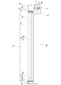
- the perspective view which expands and shows the principal part of the electric power feeder shown in FIG. The front view of the rotation cathode unit for sputtering devices to which the electric power feeder of this invention is applied.
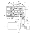
- the fragmentary sectional view which expands and shows the principal part of a rotation cathode unit.
- a shaft body and a cylinder body are an inner cylinder body and an outer cylinder body made of a conductive material such as metal.
- FM is a contact-type power feeding device of this embodiment.
- the contact type power supply device FM includes an inner cylinder 1 having a circular cross section, an outer cylinder 2 having a circular cross section disposed concentrically around the inner cylinder 1 and closed at one end (left side in FIG. 1), A driving unit 3 that rotationally drives the outer cylinder 2 and a brush Br that is disposed in a space 4 between the inner cylinder 1 and the outer cylinder 2 and that conducts the inner cylinder 1 and the outer cylinder 2 are provided.
- the driving means 3 is not particularly limited as long as the outer cylindrical body 2 can be rotated relative to the inner cylindrical body 1.
- the motor 3a, the pulley 3b provided on the driving shaft of the motor 3a, and the outer A belt 3c wound around the outer peripheral surface of the cylindrical body 2 can be used.
- the brush Br is a material that is preferentially shaved with respect to the material of the inner cylinder 1 and the outer cylinder 2, and includes a first brush piece 5 and a second brush piece 6.
- the 1st brush piece 5 and the 2nd brush piece 6 can be produced as follows, for example. That is, cylindrical members (not shown) having a thickness equivalent to the radial length between the inner cylindrical body 1 and the outer cylindrical body 2 and capable of being inserted into the space 4 are arranged at substantially equal intervals in the radial direction. Divide into a plurality of arc portions (10 divisions in this embodiment).
- the first brush piece 5 has an inner wall surface 5a that comes into surface contact with the outer circumferential surface 1a of the inner cylinder 1 and an outer surface where the second brush piece 6 comes into surface contact with the inner circumferential surface 2a of the outer cylinder 2.
- the side wall surfaces 5b and 6b as the dividing surfaces of the first brush piece 5 and the second brush piece 6 are formed in a tapered shape that is inclined with respect to the radial direction and are in surface contact with each other.
- the space 4 a is provided between the outer wall surface 5 c of the first brush piece 5 and the inner peripheral surface 2 a of the outer cylindrical body 2.
- the outer wall surface 5c of the first brush piece 5 is cut along the concentric arc of the cylindrical member, and the inner wall surface 6c of the second brush piece 6 and the outer peripheral surface 1a of the inner cylinder body 1 are provided.
- the inner wall surface 6c of the second brush piece 6 is cut along a concentric arc of the cylindrical member so that a space 4b is provided between the two.
- the 1st brush piece 5 has the outer wall surface 5c which curves in the circular arc shape concentric with the inner wall surface 5a
- the 2nd brush piece 6 is the inner wall surface which curves in the circular arc shape concentric with the outer wall surface 6a. 6c.
- the outer wall surface 5c of the first brush piece 5 and the side wall surfaces 6b and 6b of the second brush piece 6 extending radially outward from the outer wall surface 5c
- Communication paths 4a and 4b that allow liquid to pass are defined by the surface 6c and the side wall surfaces 5b and 5b of the first brush piece 5 extending radially inward from the inner wall surface 6c.
- first brush piece 5 and the second brush piece 6 are inserted into the space 4, one of the first brush pieces 5 is omitted, and the second brush pieces on both sides of the omitted first brush piece 5 are omitted.
- 6 a second brush piece 6 1, 6 2, and between the second brush piece 6 1, 6 2 of the side wall surface 6b adjacent to each other in the circumferential direction, both the second withdrawing direction with respect to the brush pieces 6 1, 6 2
- a coil spring 7 as a biasing means for applying the biasing force is contracted.
- three coil springs 7 having the same spring constant are arranged at equal intervals in the axial direction.
- the protruding piece 8 which protrudes to radial direction is provided in the outer peripheral surface 1a of the inner cylinder 1, and the inner peripheral surface 2a of the outer cylinder 2, and the 1st brush piece 5 and the 2nd brush piece 6 are made into the space 4.
- the first brush piece 5 and the second brush piece 6 may be positioned and held in the axial direction.
- the outer cylinder 2 when the outer cylinder 2 is rotated by driving the motor 3 a to rotate, the outer cylinder 2 rotates relative to the inner cylinder 1. At this time, the relative rotational speed of the outer cylindrical body 2, the frictional resistance between the outer peripheral surface 1a of the inner cylindrical body 1 and the first brush piece 5, and the friction between the inner peripheral surface 2a of the outer cylindrical body 2 and the second brush piece 6 Depending on the resistance or the like, at least one of the first brush piece 5 and the second brush piece 6 slides on the outer peripheral surface 1a of the inner cylindrical body 1 or the inner peripheral surface 2a of the outer cylindrical body 2.
- the remaining second brush pieces 6 3 to 6 5 are pushed radially outward, and the remaining first brush pieces 5 3 and 5 4 are pushed radially inward to all the first brushes.
- the piece 5 and the second brush piece 2 are in surface contact with the inner peripheral surface 2 a of the outer cylindrical body 2 and the outer peripheral surface 1 a of the inner cylindrical body 1.
- the contact between the inner cylindrical body 1 and the outer cylindrical body 2 is always ensured, and the inner cylindrical body 1 and the outer cylindrical body are secured. 2 can be efficiently passed between the inner cylinder 1 and the outer cylinder 2, and the radial thickness of the first brush piece 5 and the second brush piece 6 can be increased. As long as the biasing force of the coil spring 7 acts in the range, the contact between the brush Br and the inner cylindrical body 1 and the outer cylindrical body 2 can be ensured reliably, so that the life of the power feeding device FM can be increased.
- the first brush piece 5 1, 5 2 of the ⁇ 5a is in surface contact with the outer peripheral surface 1a of the inner cylindrical body 1, can secure a large contact area in comparison with the brush in the prior art This is advantageous when a large high-frequency current is passed.
- the axial length when the contact area between the brush, the outer peripheral surface of the inner cylindrical body and the inner peripheral surface of the outer cylindrical body is designed to be the same can be shortened, and the present invention. Therefore, it is possible to contribute to the downsizing of the device to which the power feeding device is applied.
- the space between the inner cylinder 1 and the outer cylinder 2 can be changed from the inner space 1b of the inner cylinder 1. If a liquid such as coolant or insulating hydraulic fluid is circulated through the space 4 and the communication passages 4a and 4b, the wear powder can be removed by the liquid flowing through the space 4 and the communication passages 4a and 4b. In addition, heat generated due to energization can be removed. In addition, when hydraulic fluid is used, the wear of the first brush piece 5 and the second brush piece 6 can be reduced, and the life can be extended.
- a liquid such as coolant or insulating hydraulic fluid
- the 1st brush piece 5 has the outer wall surface 5c which curves in the circular arc shape concentric with the inner wall surface 5a
- the 2nd brush piece 6 has the inner wall surface 6c which curves in the circular arc shape concentric with the outer wall surface 6a. Since it did in this way, the thickness of the radial direction of the 1st brush piece 5 and the 2nd brush piece 6 can be ensured as much as possible, the quantity which can be worn can be increased, and lifetime can be achieved further.
- the shaft body has been described as an example of the inner cylinder 1, but a solid one can be used, and the outer cylinder body 2 has been described as an example of rotational driving.
- the present invention can be applied not only to the outer cylinder 2 but also to the inner cylinder 1 and the outer cylinder 2 that are driven to rotate.
- the shaft body and the cylinder body may be divided into a plurality of parts by adding a necessary insulation distance in the axial direction, and the brush Br may be inserted between the partitioned shaft body and the cylinder body.
- the shape of the first brush piece 5 and the second brush piece 6 is such that the outer surface 1a of the inner cylinder 1 and the wall surfaces 5a and 6a that are in surface contact with the inner surface 2b of the outer cylinder 2 are in surface contact with each other. If it is provided with the side wall surfaces 5b and 6b which perform, it will not be limited to the above thing, Furthermore, the outer wall surface 5c of the 1st brush piece 5 and the inner wall surface 6c of the 2nd brush piece 6 are provided.
- the communication paths 4a and 4b are defined by cutting has been described, for example, through holes penetrating in the axial direction may be formed in the brush pieces 5 and 6 to provide the communication paths.
- a groove portion that is recessed in the radial direction is formed in the inner peripheral surface 2a of the outer cylindrical body 2 in a spiral shape over the entire length thereof, and the outer cylindrical body 2 is rotationally driven.
- the liquid circulation pump is omitted and the liquid circulates in the power supply device FM.
- the biasing means may be provided between the first brush pieces 5.
- the coil spring 7 as an urging
- the rotary cathode unit RC is provided through an insulator in a vacuum chamber (not shown) so as to face the substrate W as a film formation target in the vertical direction, and has a cylindrical shape.
- the target Tg includes a drive block 10 connected to the right end of the target Tg via a clamp Cp, and a support block 20 connected to the left end of the target Tg via a clamp Cp.
- the support block 20 is provided with a driven shaft 22 supported by a bearing 21 so as to rotatably support one end of the target Tg.
- the target Tg includes a cylindrical backing tube 31 and a cylindrical target material 32 joined to the backing tube 31 via a bonding material (not shown) such as indium or tin.
- As the target material 32 a material appropriately selected from metals and metal compounds according to the composition of the film to be deposited on the substrate W is used.
- the backing tube 31 is extrapolated to an outer tube 33 extending substantially over the entire length of the target Tg in the left-right direction, and an inner tube 34 is provided concentrically in the outer tube 33. Openings at both ends in the left-right direction of the outer tube 33 are respectively closed by cap bodies 35, and axial through holes 35 a are respectively formed in the cap bodies 35.
- the inner space of the inner pipe 34 constitutes a forward path 34a when circulating a coolant such as cooling water, and the space between the inner pipe 34 and the outer pipe 33 constitutes a return path 33a.
- a magnet unit having a known structure when installed in the space between the inner tube 34 and the outer tube 33 and a predetermined potential is applied to the target Tg and the target material 32 is sputtered.
- a leakage magnetic field is generated between the target Tg and the substrate W so that a line passing through a position where the vertical component of the magnetic field becomes zero extends along the substantially entire axial direction of the target material 32 and closes in a racetrack shape. May be.
- the drive block 10 includes a housing 11, an inner cylinder 1 extending in the left-right direction is erected on the right inner wall of the housing 11, and the left end of the inner cylinder 1 is liquid-tightly connected to the inner tube 34.
- An outer cylinder 2 is disposed around the inner cylinder 1 fixed to the housing 11 concentrically with the inner cylinder 1.
- An annular recess 2b that is recessed in the radial direction is provided on the inner peripheral surface 2a of the outer cylindrical body 2, and the second brush piece 6 of the brush Br is fitted into the recess 2b.
- the outer cylinder 2 is rotatably supported by a support member 13 inserted into the housing 11 via a plurality of bearings 12a.
- Oil seals 12b are externally inserted into the outer cylindrical body 2 so as to be positioned on both lateral sides of the bearing 12a.
- a belt 3c is wound around the outer peripheral surface 2a of the outer cylinder 2 between a pulley 3b provided on the drive shaft of the motor 3a.
- a conductive flange 14 is liquid-tightly attached to the left end of the outer cylinder 2, and is connected to the backing tube 31 through the flange 14 by a clamp Cp.
- the target Tg is rotated at a predetermined rotational speed integrally with the outer cylinder 2.
- the inner cylinder 1 is electrically connected to the outer cylinder 2 via the brush Br, and this outer cylinder 2 is electrically connected to the backing tube 31 and eventually the target material 32 via the flange 14 (that is, The inner cylinder 1 and the target material 32 have the same potential).
- a guide plate 15 that guides the refrigerant from the return path 33 a to the communication path 4 between the inner cylinder 1 and the outer cylinder 2 is extrapolated to the portion of the inner cylinder 1 that protrudes to the left from the outer cylinder 2. Yes.
- the housing 11 is provided with a forward path 17a and a return path 17b, respectively, and a conductive pipe 17 whose tip is connected to the inner cylinder 1 is provided.
- the forward path 17 a communicates with the internal space 1 b of the inner cylinder 1
- the return path 17 b communicates with the space 4 between the inner cylinder 1 and the outer cylinder 2.
- the pipe 17 communicates with the forward path 34a in the inner tube 34 from the forward path 17a of the inner cylinder 1 through the inner space 1b, and passes through the return path 33a from the through hole 35a of the left cap body 35 to pass through the through hole 35a.
- a refrigerant circulation passage is formed which communicates with the space 4 between the inner cylinder 1 and the outer cylinder 2 via the communication passage 4a and returns to the return passage 17b.
- the target material 32 exchanges heat with the refrigerant.
- an output cable 18 from a sputter power source (not shown) is connected to the pipe 17.
- a predetermined electric power having a negative potential is applied to the target material 32 via the output cable 18 from the sputtering power source while the outer cylinder 2 is rotationally driven by the motor 3a to rotationally drive the target Tg. Can do.
- FM ... Contact type power supply device inner cylinder (shaft), 1 ... inner cylinder (shaft), 1a ... outer peripheral surface, 2 ... outer cylinder (cylindrical body), 2a ... inner peripheral surface, 4 ... inner cylinder 4a, 4b ... communication path between brush pieces, Br ... brush, 5 ... first brush piece, 5a ... inner wall surface, 5b ... side wall surface, 5c ... outer wall surface, 6 ... Second brush piece, 6a ... outer wall surface, 6b ... side wall surface, 6c ... inner wall surface, 7 ... coil spring (biasing means).
Landscapes
- Chemical & Material Sciences (AREA)
- Chemical Kinetics & Catalysis (AREA)
- Engineering & Computer Science (AREA)
- Materials Engineering (AREA)
- Mechanical Engineering (AREA)
- Metallurgy (AREA)
- Organic Chemistry (AREA)
- Motor Or Generator Current Collectors (AREA)
- Brushes (AREA)
Abstract
Description
Claims (4)
- 導電性の軸体と、この軸体の周囲に同心に配置される導電性の筒体と、軸体と筒体との間の空間に配置され、軸体と筒体とが相対回転される間、軸体と筒体とを導通するブラシとを備える接触式給電装置において、
ブラシが、軸体の外周面に面接触する内璧面を持つ第1ブラシ片と、筒体の内周面に面接触する外璧面を持つ第2ブラシ片とを有してこれら第1ブラシ片と第2ブラシ片とを面接触させた状態で周方向で交互に配置して構成され、
互いに面接触する、第1ブラシ片と第2ブラシ片との側壁面の夫々が径方向に対して傾斜するテーパ状に形成され、互いに隣接する第1ブラシ片及び互いに隣接する第2ブラシ片の少なくとも一方の間に設けられて、第1ブラシ片または第2ブラシ片に対して離間方向の付勢力を付与する付勢手段を設けることを特徴とする接触式給電装置。 - 請求項1記載の給電装置であって、前記軸体が筒状であるものにおいて、前記第1ブラシ片の外璧面と前記筒体の内壁面との間及び、前記第2ブラシ片の内璧面と前記軸体の外壁面との間に空間を夫々設け、
第1ブラシ片の外璧面とこの外璧面から径方向外方に延出する第2ブラシ片の側壁面とで及び、第2ブラシ片の内璧面とこの内壁面から径方向内方に延出する第1ブラシ片の側壁面とで液体の通過を許容する連通路が画成されるようにしたことを特徴とする接触式給電装置。 - 第1ブラシ片が内璧面と同心の円弧状に湾曲する外壁面を有し、第2ブラシ片が外璧面と同心の円弧状に湾曲する内壁面を有することを特徴とする請求項2記載の接触式給電装置。
- 前記付勢手段は、第1ブラシ片の側壁面の間または第2ブラシ片の側壁面の間に縮設されるコイルばねであり、コイルばねの複数本が軸方向に所定間隔を存して配置されることを特徴とする請求項1~請求項3のいずれか1項に記載の接触式給電装置。
Priority Applications (4)
| Application Number | Priority Date | Filing Date | Title |
|---|---|---|---|
| KR1020177024960A KR101806912B1 (ko) | 2015-02-16 | 2016-01-08 | 접촉식 급전 장치 |
| CN201680006746.0A CN107210571B (zh) | 2015-02-16 | 2016-01-08 | 接触式供电装置 |
| US15/548,868 US9929526B2 (en) | 2015-02-16 | 2016-01-08 | Contact type power feeding apparatus |
| JP2017500311A JP6168716B2 (ja) | 2015-02-16 | 2016-01-08 | 接触式給電装置 |
Applications Claiming Priority (2)
| Application Number | Priority Date | Filing Date | Title |
|---|---|---|---|
| JP2015027273 | 2015-02-16 | ||
| JP2015-027273 | 2015-02-16 |
Publications (1)
| Publication Number | Publication Date |
|---|---|
| WO2016132663A1 true WO2016132663A1 (ja) | 2016-08-25 |
Family
ID=56689366
Family Applications (1)
| Application Number | Title | Priority Date | Filing Date |
|---|---|---|---|
| PCT/JP2016/000091 Ceased WO2016132663A1 (ja) | 2015-02-16 | 2016-01-08 | 接触式給電装置 |
Country Status (6)
| Country | Link |
|---|---|
| US (1) | US9929526B2 (ja) |
| JP (1) | JP6168716B2 (ja) |
| KR (1) | KR101806912B1 (ja) |
| CN (1) | CN107210571B (ja) |
| TW (1) | TWI605651B (ja) |
| WO (1) | WO2016132663A1 (ja) |
Cited By (3)
| Publication number | Priority date | Publication date | Assignee | Title |
|---|---|---|---|---|
| JP2018131644A (ja) * | 2017-02-13 | 2018-08-23 | 株式会社アルバック | スパッタリング装置用の回転式カソードユニット |
| CN109943817A (zh) * | 2017-12-20 | 2019-06-28 | 佳能特机株式会社 | 溅射装置及其使用方法 |
| JP6646798B1 (ja) * | 2018-10-17 | 2020-02-14 | 株式会社アルバック | 接触式給電装置及び接触ユニット |
Families Citing this family (7)
| Publication number | Priority date | Publication date | Assignee | Title |
|---|---|---|---|---|
| DE112017007408B4 (de) * | 2017-04-06 | 2021-01-28 | Ulvac, Inc. | Ionenquelle und Ionenimplantationsvorrichtung |
| US11118277B2 (en) | 2017-12-15 | 2021-09-14 | Sumitomo Electric Toyama Co., Ltd. | Method for producing metal porous body, and plating apparatus |
| KR102227227B1 (ko) * | 2017-12-15 | 2021-03-11 | 도야마 스미토모 덴코우 가부시키가이샤 | 금속 다공체의 제조 방법 및, 도금 처리 장치 |
| DE102019112585A1 (de) * | 2019-05-14 | 2020-11-19 | VON ARDENNE Asset GmbH & Co. KG | Magnetron-Endblockgehäuse, Magnetron-Endblock und Verfahren |
| CN117280551A (zh) * | 2021-05-06 | 2023-12-22 | 采埃孚股份公司 | 用于在可旋转的轴与壳体之间建立导电连接的轴接地装置 |
| CN115287618A (zh) * | 2022-08-26 | 2022-11-04 | 中科纳微真空科技(合肥)有限公司 | 一种锥面传输功率的旋转阴极端头 |
| CN121688477B (zh) * | 2026-02-11 | 2026-05-26 | 中国电建集团四平线路器材有限公司 | 一种管母滑动支撑引流用伸缩金具 |
Citations (3)
| Publication number | Priority date | Publication date | Assignee | Title |
|---|---|---|---|---|
| JP3974541B2 (ja) * | 2002-03-14 | 2007-09-12 | スパッタリング・コンポーネンツ・インコーポレイテッド | 高出力イオンスパッタリングマグネトロン |
| JP2008263775A (ja) * | 2008-05-19 | 2008-10-30 | Aisin Seiki Co Ltd | 直流ブラシモータ |
| JP2010124526A (ja) * | 2008-11-17 | 2010-06-03 | Toyota Central R&D Labs Inc | 回転電機 |
Family Cites Families (11)
| Publication number | Priority date | Publication date | Assignee | Title |
|---|---|---|---|---|
| US4334166A (en) * | 1977-01-19 | 1982-06-08 | Kanto Kasei Kogyo Kabushiki Kaisha | Rotary magnetic sensor |
| US4885496A (en) * | 1987-07-24 | 1989-12-05 | Black & Decker Inc. | Stator end member and assemblies therewith and methods of assembly |
| US5804903A (en) * | 1993-10-22 | 1998-09-08 | Fisher; Rodney R. | Motor shaft discharge device |
| US5384627A (en) * | 1994-03-21 | 1995-01-24 | Xerox Corporation | Developing unit having ceramic donor roll |
| JP2003061300A (ja) * | 2001-08-10 | 2003-02-28 | Victor Co Of Japan Ltd | ハードディスクドライブ用スピンドルモータ |
| US6841057B2 (en) * | 2002-03-13 | 2005-01-11 | Applied Materials Inc. | Method and apparatus for substrate polishing |
| CN1178339C (zh) * | 2002-05-30 | 2004-12-01 | 武汉华之洋光电系统有限责任公司 | 一种旋转电接触装置 |
| US9349576B2 (en) * | 2006-03-17 | 2016-05-24 | Angstrom Sciences, Inc. | Magnetron for cylindrical targets |
| US9605952B2 (en) * | 2012-03-08 | 2017-03-28 | Quality Manufacturing Inc. | Touch sensitive robotic gripper |
| JP2014143155A (ja) | 2013-01-24 | 2014-08-07 | Hisawa Giken Co Ltd | スパイラル集電子 |
| DE102015107809B3 (de) * | 2015-05-19 | 2016-07-28 | Von Ardenne Gmbh | Endblockanordnung, Prozessieranordnung damit, Lageranordnung und Verfahren zum Herstellen einer Lageranordnung |
-
2016
- 2016-01-08 CN CN201680006746.0A patent/CN107210571B/zh active Active
- 2016-01-08 US US15/548,868 patent/US9929526B2/en active Active
- 2016-01-08 JP JP2017500311A patent/JP6168716B2/ja active Active
- 2016-01-08 KR KR1020177024960A patent/KR101806912B1/ko active Active
- 2016-01-08 WO PCT/JP2016/000091 patent/WO2016132663A1/ja not_active Ceased
- 2016-01-18 TW TW105101399A patent/TWI605651B/zh active
Patent Citations (3)
| Publication number | Priority date | Publication date | Assignee | Title |
|---|---|---|---|---|
| JP3974541B2 (ja) * | 2002-03-14 | 2007-09-12 | スパッタリング・コンポーネンツ・インコーポレイテッド | 高出力イオンスパッタリングマグネトロン |
| JP2008263775A (ja) * | 2008-05-19 | 2008-10-30 | Aisin Seiki Co Ltd | 直流ブラシモータ |
| JP2010124526A (ja) * | 2008-11-17 | 2010-06-03 | Toyota Central R&D Labs Inc | 回転電機 |
Cited By (9)
| Publication number | Priority date | Publication date | Assignee | Title |
|---|---|---|---|---|
| JP2018131644A (ja) * | 2017-02-13 | 2018-08-23 | 株式会社アルバック | スパッタリング装置用の回転式カソードユニット |
| CN109943817A (zh) * | 2017-12-20 | 2019-06-28 | 佳能特机株式会社 | 溅射装置及其使用方法 |
| JP2019108602A (ja) * | 2017-12-20 | 2019-07-04 | キヤノントッキ株式会社 | スパッタ装置及びその使用方法 |
| CN109943817B (zh) * | 2017-12-20 | 2023-04-11 | 佳能特机株式会社 | 溅射装置及其使用方法 |
| JP6646798B1 (ja) * | 2018-10-17 | 2020-02-14 | 株式会社アルバック | 接触式給電装置及び接触ユニット |
| WO2020079881A1 (ja) * | 2018-10-17 | 2020-04-23 | 株式会社アルバック | 接触式給電装置及び接触ユニット |
| KR20210071946A (ko) * | 2018-10-17 | 2021-06-16 | 가부시키가이샤 아루박 | 접촉식 급전장치 및 접촉유닛 |
| US11462873B2 (en) | 2018-10-17 | 2022-10-04 | Ulvac, Inc. | Contact-type power supply apparatus and contact unit |
| KR102666846B1 (ko) | 2018-10-17 | 2024-05-20 | 가부시키가이샤 아루박 | 접촉식 급전장치 및 접촉유닛 |
Also Published As
| Publication number | Publication date |
|---|---|
| JPWO2016132663A1 (ja) | 2017-07-20 |
| CN107210571B (zh) | 2018-08-07 |
| JP6168716B2 (ja) | 2017-07-26 |
| KR101806912B1 (ko) | 2017-12-08 |
| CN107210571A (zh) | 2017-09-26 |
| US9929526B2 (en) | 2018-03-27 |
| US20180048104A1 (en) | 2018-02-15 |
| TWI605651B (zh) | 2017-11-11 |
| TW201637313A (zh) | 2016-10-16 |
| KR20170106492A (ko) | 2017-09-20 |
Similar Documents
| Publication | Publication Date | Title |
|---|---|---|
| JP6168716B2 (ja) | 接触式給電装置 | |
| JP6507393B2 (ja) | すべり軸受及びポンプ | |
| CN107786017B (zh) | 旋转电机的转子结构 | |
| WO2017018067A1 (ja) | 回転電機冷却構造 | |
| US20220320953A1 (en) | Motor unit | |
| EP2977615A1 (en) | Electric pump | |
| JP2015226465A (ja) | 電気ポンプ | |
| JP6550698B2 (ja) | 電動ポンプ | |
| US20160053807A1 (en) | Bearing for a rotary machine | |
| JP2016044673A (ja) | 動圧軸受ポンプ | |
| JP2019050707A (ja) | 回転電機の油冷及びベアリング潤滑構造 | |
| CN115085415B (zh) | 转子组件和包括该转子组件的电机 | |
| CN110535279B (zh) | 马达 | |
| JP2016119760A (ja) | 回転電機 | |
| DE102022122183A1 (de) | Elektrische Maschine | |
| JP2017017940A (ja) | スリップリング機構 | |
| WO2020079881A1 (ja) | 接触式給電装置及び接触ユニット | |
| JP2018520629A (ja) | 最適な冷却のための電気回転機械 | |
| JP5471383B2 (ja) | モータの冷却装置 | |
| JP2008079388A (ja) | ブラシ装置及びそのブラシ装置を備える燃料ポンプ | |
| JP6195167B2 (ja) | モータ | |
| KR102856928B1 (ko) | 모터 | |
| JP2001224148A (ja) | モータの軸受装置 | |
| JP2018131644A (ja) | スパッタリング装置用の回転式カソードユニット | |
| JP2019183766A (ja) | 電動ポンプ |
Legal Events
| Date | Code | Title | Description |
|---|---|---|---|
| 121 | Ep: the epo has been informed by wipo that ep was designated in this application |
Ref document number: 16752056 Country of ref document: EP Kind code of ref document: A1 |
|
| ENP | Entry into the national phase |
Ref document number: 2017500311 Country of ref document: JP Kind code of ref document: A |
|
| WWE | Wipo information: entry into national phase |
Ref document number: 15548868 Country of ref document: US |
|
| NENP | Non-entry into the national phase |
Ref country code: DE |
|
| ENP | Entry into the national phase |
Ref document number: 20177024960 Country of ref document: KR Kind code of ref document: A |
|
| 122 | Ep: pct application non-entry in european phase |
Ref document number: 16752056 Country of ref document: EP Kind code of ref document: A1 |