WO2016132644A1 - 遠心圧縮機および過給機 - Google Patents
遠心圧縮機および過給機 Download PDFInfo
- Publication number
- WO2016132644A1 WO2016132644A1 PCT/JP2015/085451 JP2015085451W WO2016132644A1 WO 2016132644 A1 WO2016132644 A1 WO 2016132644A1 JP 2015085451 W JP2015085451 W JP 2015085451W WO 2016132644 A1 WO2016132644 A1 WO 2016132644A1
- Authority
- WO
- WIPO (PCT)
- Prior art keywords
- groove
- upstream
- wall
- impeller
- downstream
- Prior art date
- Legal status (The legal status is an assumption and is not a legal conclusion. Google has not performed a legal analysis and makes no representation as to the accuracy of the status listed.)
- Ceased
Links
Images



Classifications
-
- F—MECHANICAL ENGINEERING; LIGHTING; HEATING; WEAPONS; BLASTING
- F02—COMBUSTION ENGINES; HOT-GAS OR COMBUSTION-PRODUCT ENGINE PLANTS
- F02B—INTERNAL-COMBUSTION PISTON ENGINES; COMBUSTION ENGINES IN GENERAL
- F02B39/00—Component parts, details, or accessories relating to, driven charging or scavenging pumps, not provided for in groups F02B33/00 - F02B37/00
-
- F—MECHANICAL ENGINEERING; LIGHTING; HEATING; WEAPONS; BLASTING
- F04—POSITIVE - DISPLACEMENT MACHINES FOR LIQUIDS; PUMPS FOR LIQUIDS OR ELASTIC FLUIDS
- F04D—NON-POSITIVE-DISPLACEMENT PUMPS
- F04D29/00—Details, component parts, or accessories
- F04D29/40—Casings; Connections of working fluid
- F04D29/42—Casings; Connections of working fluid for radial or helico-centrifugal pumps
- F04D29/44—Fluid-guiding means, e.g. diffusers
- F04D29/441—Fluid-guiding means, e.g. diffusers especially adapted for elastic fluid pumps
-
- F—MECHANICAL ENGINEERING; LIGHTING; HEATING; WEAPONS; BLASTING
- F04—POSITIVE - DISPLACEMENT MACHINES FOR LIQUIDS; PUMPS FOR LIQUIDS OR ELASTIC FLUIDS
- F04D—NON-POSITIVE-DISPLACEMENT PUMPS
- F04D17/00—Radial-flow pumps, e.g. centrifugal pumps; Helico-centrifugal pumps
- F04D17/08—Centrifugal pumps
- F04D17/10—Centrifugal pumps for compressing or evacuating
-
- F—MECHANICAL ENGINEERING; LIGHTING; HEATING; WEAPONS; BLASTING
- F04—POSITIVE - DISPLACEMENT MACHINES FOR LIQUIDS; PUMPS FOR LIQUIDS OR ELASTIC FLUIDS
- F04D—NON-POSITIVE-DISPLACEMENT PUMPS
- F04D29/00—Details, component parts, or accessories
- F04D29/26—Rotors specially for elastic fluids
- F04D29/28—Rotors specially for elastic fluids for centrifugal or helico-centrifugal pumps for radial-flow or helico-centrifugal pumps
- F04D29/284—Rotors specially for elastic fluids for centrifugal or helico-centrifugal pumps for radial-flow or helico-centrifugal pumps for compressors
-
- F—MECHANICAL ENGINEERING; LIGHTING; HEATING; WEAPONS; BLASTING
- F04—POSITIVE - DISPLACEMENT MACHINES FOR LIQUIDS; PUMPS FOR LIQUIDS OR ELASTIC FLUIDS
- F04D—NON-POSITIVE-DISPLACEMENT PUMPS
- F04D29/00—Details, component parts, or accessories
- F04D29/40—Casings; Connections of working fluid
- F04D29/42—Casings; Connections of working fluid for radial or helico-centrifugal pumps
- F04D29/4206—Casings; Connections of working fluid for radial or helico-centrifugal pumps especially adapted for elastic fluid pumps
-
- F—MECHANICAL ENGINEERING; LIGHTING; HEATING; WEAPONS; BLASTING
- F04—POSITIVE - DISPLACEMENT MACHINES FOR LIQUIDS; PUMPS FOR LIQUIDS OR ELASTIC FLUIDS
- F04D—NON-POSITIVE-DISPLACEMENT PUMPS
- F04D29/00—Details, component parts, or accessories
- F04D29/40—Casings; Connections of working fluid
- F04D29/42—Casings; Connections of working fluid for radial or helico-centrifugal pumps
- F04D29/4206—Casings; Connections of working fluid for radial or helico-centrifugal pumps especially adapted for elastic fluid pumps
- F04D29/4213—Casings; Connections of working fluid for radial or helico-centrifugal pumps especially adapted for elastic fluid pumps suction ports
-
- F—MECHANICAL ENGINEERING; LIGHTING; HEATING; WEAPONS; BLASTING
- F04—POSITIVE - DISPLACEMENT MACHINES FOR LIQUIDS; PUMPS FOR LIQUIDS OR ELASTIC FLUIDS
- F04D—NON-POSITIVE-DISPLACEMENT PUMPS
- F04D29/00—Details, component parts, or accessories
- F04D29/66—Combating cavitation, whirls, noise, vibration or the like; Balancing
- F04D29/68—Combating cavitation, whirls, noise, vibration or the like; Balancing by influencing boundary layers
- F04D29/681—Combating cavitation, whirls, noise, vibration or the like; Balancing by influencing boundary layers especially adapted for elastic fluid pumps
-
- F—MECHANICAL ENGINEERING; LIGHTING; HEATING; WEAPONS; BLASTING
- F04—POSITIVE - DISPLACEMENT MACHINES FOR LIQUIDS; PUMPS FOR LIQUIDS OR ELASTIC FLUIDS
- F04D—NON-POSITIVE-DISPLACEMENT PUMPS
- F04D29/00—Details, component parts, or accessories
- F04D29/66—Combating cavitation, whirls, noise, vibration or the like; Balancing
- F04D29/68—Combating cavitation, whirls, noise, vibration or the like; Balancing by influencing boundary layers
- F04D29/681—Combating cavitation, whirls, noise, vibration or the like; Balancing by influencing boundary layers especially adapted for elastic fluid pumps
- F04D29/685—Inducing localised fluid recirculation in the stator-rotor interface
-
- F—MECHANICAL ENGINEERING; LIGHTING; HEATING; WEAPONS; BLASTING
- F02—COMBUSTION ENGINES; HOT-GAS OR COMBUSTION-PRODUCT ENGINE PLANTS
- F02B—INTERNAL-COMBUSTION PISTON ENGINES; COMBUSTION ENGINES IN GENERAL
- F02B33/00—Engines characterised by provision of pumps for charging or scavenging
- F02B33/32—Engines with pumps other than of reciprocating-piston type
- F02B33/34—Engines with pumps other than of reciprocating-piston type with rotary pumps
- F02B33/40—Engines with pumps other than of reciprocating-piston type with rotary pumps of non-positive-displacement type
-
- F—MECHANICAL ENGINEERING; LIGHTING; HEATING; WEAPONS; BLASTING
- F02—COMBUSTION ENGINES; HOT-GAS OR COMBUSTION-PRODUCT ENGINE PLANTS
- F02B—INTERNAL-COMBUSTION PISTON ENGINES; COMBUSTION ENGINES IN GENERAL
- F02B37/00—Engines characterised by provision of pumps driven at least for part of the time by exhaust
-
- F—MECHANICAL ENGINEERING; LIGHTING; HEATING; WEAPONS; BLASTING
- F05—INDEXING SCHEMES RELATING TO ENGINES OR PUMPS IN VARIOUS SUBCLASSES OF CLASSES F01-F04
- F05D—INDEXING SCHEME FOR ASPECTS RELATING TO NON-POSITIVE-DISPLACEMENT MACHINES OR ENGINES, GAS-TURBINES OR JET-PROPULSION PLANTS
- F05D2220/00—Application
- F05D2220/40—Application in turbochargers
-
- F—MECHANICAL ENGINEERING; LIGHTING; HEATING; WEAPONS; BLASTING
- F05—INDEXING SCHEMES RELATING TO ENGINES OR PUMPS IN VARIOUS SUBCLASSES OF CLASSES F01-F04
- F05D—INDEXING SCHEME FOR ASPECTS RELATING TO NON-POSITIVE-DISPLACEMENT MACHINES OR ENGINES, GAS-TURBINES OR JET-PROPULSION PLANTS
- F05D2270/00—Control
- F05D2270/01—Purpose of the control system
- F05D2270/10—Purpose of the control system to cope with, or avoid, compressor flow instabilities
- F05D2270/101—Compressor surge or stall
-
- F—MECHANICAL ENGINEERING; LIGHTING; HEATING; WEAPONS; BLASTING
- F05—INDEXING SCHEMES RELATING TO ENGINES OR PUMPS IN VARIOUS SUBCLASSES OF CLASSES F01-F04
- F05D—INDEXING SCHEME FOR ASPECTS RELATING TO NON-POSITIVE-DISPLACEMENT MACHINES OR ENGINES, GAS-TURBINES OR JET-PROPULSION PLANTS
- F05D2270/00—Control
- F05D2270/01—Purpose of the control system
- F05D2270/17—Purpose of the control system to control boundary layer
Definitions
- the present disclosure relates to a centrifugal compressor and a turbocharger that compress intake air by rotation of an impeller.
- turbocharger in which a shaft having a turbine impeller provided at one end and a compressor impeller provided at the other end is rotatably supported by a bearing housing.
- the turbocharger is connected to the engine, and the exhaust gas discharged from the engine rotates the turbine impeller, and the rotation of the turbine impeller rotates the compressor impeller via the shaft.
- the supercharger compresses air as the compressor impeller rotates and delivers it to the engine.
- the compressor impeller side of the turbocharger functions as a so-called centrifugal compressor.
- a centrifugal compressor surging occurs in a region where the intake flow rate is small.
- Surging is a phenomenon that occurs when the high pressure intake (gas) compressed by the compressor impeller flows back to the upstream side of the compressor impeller which is the low pressure side, and this phenomenon makes the operation of the centrifugal compressor unstable. Therefore, the centrifugal compressor described in Patent Document 1 has a groove (“annular groove” in Patent Document 1) formed on the inner wall of a housing that accommodates the impeller.
- the groove is formed in an annular shape extending in the circumferential direction of the compressor impeller, and is positioned to straddle the leading edge of the blade in the compressor impeller.
- An object of the present application is to provide a centrifugal compressor and a supercharger capable of reducing pressure loss due to backflow of intake air.
- a first aspect of the present disclosure is a centrifugal compressor, which is formed on a housing having an intake passage inside, an impeller housed in the intake passage, and an inner wall of the intake passage, and extends in the rotational direction of the impeller.
- a boundary portion including a drift groove, and the groove wall forming the drift groove and the inner wall of the intake passage are continuously connected is an upstream boundary portion located on the upstream side of the flow direction of intake, and a downstream side of the flow direction
- the upstream boundary is located more inward in the radial direction of the impeller than the downstream boundary, and the drift groove is located upstream of the impeller in the flow direction Make it a gist.
- the angle between any of the groove walls of the drift groove and the tangential direction of the groove wall and any of the tangential directions of the inner wall of the intake path at the upstream boundary may be 90 degrees or less .
- the angle between any of the groove walls of the drift groove and the tangential direction of the groove wall and any of the tangential directions of the inner wall of the intake path at the downstream boundary may be 90 degrees or more .
- the drift groove extends from the upstream boundary to an upstream groove wall extending parallel to the radial direction of the impeller, and extends from the upstream groove wall to the downstream boundary and is connected to the upstream groove wall at an acute angle And a groove wall may be provided.
- a turbocharger of this indication is characterized by including the above-mentioned centrifugal compressor.
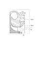
- FIG. 1 is a schematic cross-sectional view of a turbocharger according to an embodiment of the present disclosure.
- FIG. 2 is an extracted view of the broken line portion of FIG.
- FIG. 3 is an extracted view of the dashed-two dotted line portion of FIG.
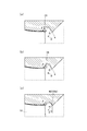
- FIGS. 4A to 4C are diagrams for explaining first to third modified examples of the present embodiment.
- FIGS. 5 (a) to 5 (c) are diagrams for explaining the fourth to sixth modified examples of the present embodiment.
- FIG. 6 is a diagram for explaining a seventh modified example of the present embodiment.
- FIG. 1 is a schematic cross-sectional view of a turbocharger C.
- arrow L shown to a figure shall be made into the direction which shows the left side of the turbocharger C
- arrow R is demonstrated as a direction which shows the right side of the turbocharger C.
- the supercharger C includes a supercharger main body 1.
- the turbocharger body 1 includes a bearing housing 2 (housing), a turbine housing 4 coupled to the left side of the bearing housing 2 by a fastening bolt 3, and a compressor housing 6 coupled to the right side of the bearing housing 2 by a fastening bolt 5 ( And a housing). These are integrated.
- a bearing hole 2 a penetrating in the left-right direction of the turbocharger C is formed in the bearing housing 2.
- the bearing 7 is accommodated in the bearing hole 2a.
- the bearing 7 rotatably supports the shaft 8.
- a turbine impeller 9 is integrally fixed to the left end of the shaft 8, and the turbine impeller 9 is rotatably accommodated in the turbine housing 4.
- a compressor impeller (impeller) 10 is integrally fixed to the right end of the shaft 8, and the compressor impeller 10 is rotatably accommodated in the compressor housing 6.
- An intake port 11 is formed in the compressor housing 6.
- the intake port 11 opens on the right side of the turbocharger C and is connected to an air cleaner (not shown). Further, in a state where the bearing housing 2 and the compressor housing 6 are connected by the fastening bolt 5, the opposing surfaces of the both housings 2 and 6 form a diffuser flow path 12 for pressurizing the gas (for example, air). .
- the diffuser flow passage 12 is annularly formed from the radially inner side to the outer side of the shaft 8. The diffuser flow passage 12 communicates with the intake port 11 via the compressor impeller 10 at the radially inner side.
- a compressor scroll channel 13 is provided in the compressor housing 6.
- the compressor scroll passage 13 is formed in an annular shape, and is positioned radially outside the shaft 8 with respect to the diffuser passage 12.
- the compressor scroll passage 13 is in communication with an intake port (not shown) of the engine.
- the compressor scroll passage 13 also communicates with the diffuser passage 12. Therefore, when the compressor impeller 10 rotates, the gas is sucked into the compressor housing 6 from the intake port 11 and boosted in the process of flowing between the blades of the compressor impeller 10, and the diffuser flow passage 12 and the compressor scroll flow passage 13 The pressure is boosted (pressure recovery) and led to the engine.
- a discharge port 14 is formed in the turbine housing 4.
- the discharge port 14 opens on the left side of the turbocharger C and is connected to an exhaust gas purification device (not shown).
- the turbine housing 4 is provided with a flow passage 15 and an annular turbine scroll flow passage 16 positioned radially outside the shaft 8 with respect to the flow passage 15.
- the turbine scroll passage 16 communicates with a gas inlet (not shown) to which exhaust gas discharged from an exhaust manifold (not shown) of the engine is introduced.
- the turbine scroll passage 16 is also in communication with the passage 15. Therefore, the exhaust gas is led from the gas inlet to the turbine scroll passage 16 and is led to the discharge port 14 through the passage 15 and the turbine impeller 9. In this circulation process, the exhaust gas rotates the turbine impeller 9.
- the rotational force of the turbine impeller 9 is transmitted to the compressor impeller 10 via the shaft 8, whereby the compressor impeller 10 rotates.
- the gas is pressurized by the rotational force of the compressor impeller 10 and is led to the engine.
- the component on the compressor housing 6 side is a centrifugal compressor CC that compresses intake air (gas) introduced from the intake port 11 to the diffuser flow path 12 by rotation of the compressor impeller 10. Function.
- FIG. 2 is an extracted view of the broken line portion of FIG.
- the intake passage 17 is a flow passage of gas communicating from the intake port 11 to the diffuser passage 12.
- the intake passage 17 guides the intake air flowing in from the intake 11 to the diffuser passage 12.
- the compressor impeller 10 is accommodated in the intake passage 17.
- a drift groove 18 is formed on the inner wall 17 a of the intake passage 17.
- the drift groove 18 is an annular groove extending in the rotational direction of the compressor impeller 10.
- the drift groove 18 is disposed closer to the intake port 11 than the compressor impeller 10 in the axial direction of the compressor impeller 10.
- the drift groove 18 is positioned upstream of the compressor impeller 10 in the flow direction of intake air (the direction from the intake port 11 to the compressor impeller 10).
- the end 18 a (the end on the left side in FIG. 2) of the drift groove 18 is located closer to the intake port 11 than the end 10 a on the intake port 11 side of the compressor impeller 10.
- FIG. 3 is an extracted view of the dashed-two dotted line portion of FIG.
- the boundary where the groove wall 18b forming the drift groove 18 and the inner wall 17a of the intake passage 17 are continuously connected is located on the upstream side (right side in FIG. 3) of the flow direction of intake.
- a downstream boundary 20 located on the downstream side (left side in FIG. 3) of the flow direction of the intake air.
- the boundary portion is formed by connecting the groove wall 18 b and the inner wall 17 a of the intake passage 17 to each other.
- the upstream side boundary portion 19 is positioned inside (lower side in FIG. 3) in the radial direction of the compressor impeller 10 than the downstream side boundary portion 20.
- FIG. 3 shows, for example, a flat cross section including the rotation shaft of the compressor impeller 10. As shown in this figure, the upstream boundary 19 and the downstream boundary 20 have a curved shape.
- the angle ⁇ between the tangential direction of the groove wall 18b and the tangential direction of the inner wall 17a of the intake passage 17 is 90 degrees or less.
- an angle ⁇ between the tangential direction of the groove wall 18b and the tangential direction of the inner wall 17a of the intake passage 17 is 90 degrees or more.
- the groove wall 18b of the drift groove 18 includes an upstream groove wall 18c and a downstream groove wall 18d.
- the upstream groove wall portion 18 c is a portion extending from the upstream side boundary portion 19 in parallel with the radial direction of the compressor impeller 10.
- the downstream groove wall 18 d is a portion extending from the downstream boundary 20 to the upstream groove wall 18 c.
- the boundary 21 between the upstream groove wall 18 c and the downstream groove wall 18 d has a curved shape.
- an angle ⁇ formed by the tangential direction of each of the upstream groove wall portion 18c and the downstream groove wall portion 18d is an acute angle.
- the intake air flowing back in this way flows from the inner wall 17 a of the intake passage 17 along the groove wall 18 b of the drift groove 18 by centrifugal force. Specifically, the flow of intake air flowing backward from the downstream groove wall portion 18 d toward the upstream groove wall portion 18 c flows inside the drift groove 18, and the flow direction is changed (biased) to join the mainstream of the intake air. .
- the upstream groove wall portion 18c protruding radially inward functions as a "reflector" of the reverse flow, and reduces interference (mixing loss) due to merging with the main flow of intake. Therefore, the loss due to the backflow of the intake can be reduced.
- FIGS. 4 (a) to 4 (c) are diagrams for explaining the first to third modified examples.
- the angle ⁇ is an acute angle, as in the embodiment described above.
- the angle ⁇ is an acute angle.
- the angle ⁇ is 90 degrees or less, and the angle ⁇ is a right angle.
- the angle ⁇ is 90 degrees or less and the angle ⁇ is 90 degrees or more, as in the embodiment described above.
- the groove wall 48b of the drift groove 48 has a curved shape as shown in FIG.
- 5 (a) to 5 (c) are diagrams for explaining the fourth to sixth modified examples.
- the angle ⁇ is 90 degrees or less
- the angle ⁇ is a right angle
- the angle ⁇ is an acute angle.
- the upstream groove wall portion 58c is inclined with respect to the radial direction of the compressor impeller 10
- the downstream groove wall portion 58d is parallel to the radial direction of the compressor impeller 10.
- the angle ⁇ is 90 degrees or less, and the angle ⁇ is 90 degrees or more, as in the embodiment described above.
- a bottom surface 68 e extending in the rotational axis direction of the compressor impeller 10 is formed between the upstream groove wall 68 c and the downstream groove wall 68 d.
- the angle ⁇ is 90 degrees or less, and the angle ⁇ is 90 degrees or more.
- the upstream groove wall portion 78 c is parallel to the radial direction of the compressor impeller 10.
- the shape of the drift groove according to the present disclosure can be variously modified. That is, as long as the above-mentioned condition is satisfied, the shape of the drift groove is not limited to that illustrated.
- the upstream boundary 19, the downstream boundary 20, and the boundary 21 between the upstream groove wall 18c and the downstream groove wall 18d have curved shapes as shown in FIG. ing.
- one of the upstream groove wall portion 18c and the inner wall 17a of the intake passage 17 at the upstream side boundary portion 19 has a shape shown by a curve in the cross section shown in FIG. 3 and the other is shown by a straight line It may have a shape. Alternatively, both may have a shape shown by a straight line in the cross section shown in FIG.
- one of the downstream groove wall 18 d and the inner wall 17 a of the intake passage 17 at the downstream boundary 20 has a shape shown by a curve in the cross section shown in FIG. 3 and the other is shown by a straight line It may have a shape. Moreover, both may have a shape shown by a straight line in the cross section shown in FIG.
- either the upstream groove wall 18c or the downstream groove wall 18d has a shape shown by a curve in the cross section shown in FIG.
- one or the other may have a shape shown by a straight line.
- both may have a shape shown by a straight line in the cross section shown in FIG.
- the angle ⁇ is any one of the tangential directions of the upstream groove wall 18c and the upstream groove wall 18c in the upstream boundary 19, and the tangential direction of the inner wall 17a and the inner wall 17a of the intake passage 17. It is the corner that forms with either.
- the angle ⁇ is any one of the tangential directions of the downstream groove wall 18 d and the downstream groove wall 18 d at the downstream boundary 20 and any of the tangential directions of the inner wall 17 a and the inner wall 17 a of the intake passage 17. It is the corner of
- the angle ⁇ is any one of the tangential directions of the upstream groove wall 18c and the upstream groove wall 18c at the boundary 21 between the upstream groove wall 18c and the downstream groove wall 18d, the downstream groove wall 18d and the downstream It is an angle formed with one of the tangential directions of the groove wall 18 d.
- the angle ⁇ is 90 degrees or less
- the angle ⁇ may be an obtuse angle.
- the intake air joined from within the drift grooves 18, 28, 38, 48, 58, 68, 78 than in the case of the obtuse angle. Can be reduced along the flow direction from the drift grooves 18, 28, 38, 48, 58, 68, 78 to reduce the mixing loss. That is, stable deflection effect (function as a deflector) is obtained by the drift grooves 18, 28, 38, 48, 58, 68, 78.
- the angle ⁇ is 90 degrees or more has been described, but the angle ⁇ may be an acute angle.
- the drift grooves 18, 38, 48, 58 compared to the case where the angle ⁇ is an acute angle. It is possible to make it easy to introduce the backflowed intake air into 68, 78.
- the upstream groove wall portion 18c extends in parallel with the radial direction of the compressor impeller 10, and the case where the angle ⁇ is an acute angle has been described.
- the upstream groove wall portion 58 c may be inclined with respect to the radial direction of the compressor impeller 10.
- the upstream groove wall portion 58c parallel to the radial direction of the compressor impeller 10 and making the angle ⁇ an acute angle, the direction of intake air joining the mainstream from the drift groove 18 is along the mainstream flow direction. Mixing loss can be reduced.
- the wetting edge (surface area) of the deflecting groove 18 can be reduced by forming the deflecting grooves 18 and 58 by the V-shaped cut, and the inside of the deflecting groove 18 can be reduced. Friction loss with flowing intake can be reduced.
- FIG. 6 is a diagram for explaining the seventh modified example, and is an extracted view of a portion corresponding to FIG. 2 in the seventh modified example.
- the compressor housing 6 according to the seventh modification includes a main body 6 a and an annular member 6 b.
- a large diameter portion 17 b and a small diameter portion 17 c are formed on the inner wall 17 a of the intake passage 17 in the main body portion 6 a in order from the side of the intake port 11.
- the large diameter portion 17b is larger in inner diameter than the small diameter portion 17c, and at the boundary between the large diameter portion 17b and the small diameter portion 17c, a tapered portion 17d is formed to be inclined toward the inner diameter toward the intake port 11 .
- the annular member 6b is fitted in and fixed to the large diameter portion 17b.
- the radial direction position of the compressor impeller 10 is located more inward than the tapered portion 17d of the end portion 6c on the inner peripheral side of the annular member 6b.
- a groove formed by the tapered portion 17 d and the annular member 6 b becomes a drift groove 88.
- the compressor housing 6 includes the main body 6a and the annular member 6b, it is possible to reduce the loss due to the backflow of the intake air, as in the above-described embodiment. Further, if the tapered portion 17d is processed before assembling the annular member 6b, since the drift groove 88 can be formed, the processability can be improved. Further, the radial position of the end 6c of the annular member 6b can be easily changed only by replacing the annular member 6b.
Landscapes
- Engineering & Computer Science (AREA)
- Mechanical Engineering (AREA)
- General Engineering & Computer Science (AREA)
- Chemical & Material Sciences (AREA)
- Combustion & Propulsion (AREA)
- Structures Of Non-Positive Displacement Pumps (AREA)
- Supercharger (AREA)
Abstract
Description
Claims (5)
- 内部に吸気路を有するハウジングと、
前記吸気路内に収容されたインペラと、
前記吸気路の内壁に形成され、前記インペラの回転方向に延在する偏流溝と
を備え、
前記偏流溝を形成する溝壁と前記吸気路の内壁とが連続的に接続する境界部は、吸気の流通方向の上流側に位置する上流側境界部と、前記流通方向の下流側に位置する下流側境界部とを含み、
前記上流側境界部は、前記下流側境界部よりも、前記インペラの径方向において内側に位置し、
前記偏流溝は、前記流通方向において前記インペラよりも上流側に位置する遠心圧縮機。 - 前記上流側境界部における、前記偏流溝の前記溝壁及び前記溝壁の接線方向のうちの何れかと、前記吸気路の内壁及び前記内壁の接線方向のうちの何れかとの成す角は、90度以下である請求項1に記載の遠心圧縮機。
- 前記下流側境界部における、前記偏流溝の前記溝壁及び前記溝壁の接線方向のうちの何れかと、前記吸気路の内壁及び前記内壁の接線方向のうちの何れかとの成す角は、90度以上である請求項1または2に記載の遠心圧縮機。
- 前記偏流溝は、前記上流側境界部から前記インペラの径方向と平行に延在する上流溝壁部と、前記上流溝壁部から前記下流側境界部まで延在するとともに、前記上流溝壁部に鋭角に接続する下流溝壁部と、を備える請求項1から3のうちの何れか1項に記載の遠心圧縮機。
- 前記請求項1から4のうちの何れか1項に記載の遠心圧縮機を備える過給機。
Priority Applications (4)
| Application Number | Priority Date | Filing Date | Title |
|---|---|---|---|
| JP2017500301A JP6369621B2 (ja) | 2015-02-18 | 2015-12-18 | 遠心圧縮機および過給機 |
| CN201580075531.XA CN107208658B (zh) | 2015-02-18 | 2015-12-18 | 离心压缩机及增压器 |
| DE112015004675.5T DE112015004675T5 (de) | 2015-02-18 | 2015-12-18 | Zentrifugalkompressor und Turbolader |
| US15/468,278 US10364825B2 (en) | 2015-02-18 | 2017-03-24 | Centrifugal compressor and turbocharger |
Applications Claiming Priority (2)
| Application Number | Priority Date | Filing Date | Title |
|---|---|---|---|
| JP2015029784 | 2015-02-18 | ||
| JP2015-029784 | 2015-02-18 |
Related Child Applications (1)
| Application Number | Title | Priority Date | Filing Date |
|---|---|---|---|
| US15/468,278 Continuation US10364825B2 (en) | 2015-02-18 | 2017-03-24 | Centrifugal compressor and turbocharger |
Publications (1)
| Publication Number | Publication Date |
|---|---|
| WO2016132644A1 true WO2016132644A1 (ja) | 2016-08-25 |
Family
ID=56692697
Family Applications (1)
| Application Number | Title | Priority Date | Filing Date |
|---|---|---|---|
| PCT/JP2015/085451 Ceased WO2016132644A1 (ja) | 2015-02-18 | 2015-12-18 | 遠心圧縮機および過給機 |
Country Status (5)
| Country | Link |
|---|---|
| US (1) | US10364825B2 (ja) |
| JP (1) | JP6369621B2 (ja) |
| CN (1) | CN107208658B (ja) |
| DE (1) | DE112015004675T5 (ja) |
| WO (1) | WO2016132644A1 (ja) |
Cited By (1)
| Publication number | Priority date | Publication date | Assignee | Title |
|---|---|---|---|---|
| WO2020021816A1 (ja) * | 2018-07-24 | 2020-01-30 | 株式会社Ihi | 圧縮機および圧縮システム |
Families Citing this family (9)
| Publication number | Priority date | Publication date | Assignee | Title |
|---|---|---|---|---|
| CN109372799A (zh) * | 2018-11-30 | 2019-02-22 | 湖南天雁机械有限责任公司 | 叶轮导风腔旁通再循环涡轮增压器压气机 |
| DE102018132978A1 (de) * | 2018-12-19 | 2020-06-25 | Ebm-Papst Mulfingen Gmbh & Co. Kg | Turboverdichter mit angepasster Meridiankontur der Schaufeln und Verdichterwand |
| US11143201B2 (en) * | 2019-03-15 | 2021-10-12 | Pratt & Whitney Canada Corp. | Impeller tip cavity |
| US11725668B2 (en) * | 2019-03-19 | 2023-08-15 | Mitsubishi Heavy Industries Engine & Turbocharger, Ltd. | Centrifugal compressor and turbocharger |
| US12031552B2 (en) * | 2019-04-15 | 2024-07-09 | Wuxi Cummins Turbo Technologies Company Ltd. | Compressor |
| US11268536B1 (en) | 2020-09-08 | 2022-03-08 | Pratt & Whitney Canada Corp. | Impeller exducer cavity with flow recirculation |
| DE102020128922A1 (de) * | 2020-11-03 | 2022-05-05 | Borgwarner Inc. | Verstellmechanismus mit lärmreduzierenden merkmalen |
| CN116529490B (zh) | 2020-12-03 | 2025-12-23 | 丹佛斯公司 | 包括带凹槽的扩散器的制冷剂压缩机 |
| WO2022172667A1 (ja) * | 2021-02-09 | 2022-08-18 | 株式会社Ihi | 回転機械 |
Citations (2)
| Publication number | Priority date | Publication date | Assignee | Title |
|---|---|---|---|---|
| JPS63128298U (ja) * | 1987-10-22 | 1988-08-22 | ||
| JPH0417198U (ja) * | 1990-05-31 | 1992-02-13 |
Family Cites Families (41)
| Publication number | Priority date | Publication date | Assignee | Title |
|---|---|---|---|---|
| GB858808A (en) * | 1957-03-12 | 1961-01-18 | Willy Amme | Radial-flow fan or pump |
| US4063848A (en) * | 1976-03-24 | 1977-12-20 | Caterpillar Tractor Co. | Centrifugal compressor vaneless space casing treatment |
| US4212585A (en) * | 1978-01-20 | 1980-07-15 | Northern Research And Engineering Corporation | Centrifugal compressor |
| JPS5818600A (ja) | 1981-07-23 | 1983-02-03 | Mitsubishi Heavy Ind Ltd | 送風圧縮機 |
| FI69683C (fi) * | 1982-02-08 | 1986-03-10 | Ahlstroem Oy | Centrifugalpump foer vaetskor innehaollande fasta aemnen |
| JPS6050298A (ja) * | 1983-08-29 | 1985-03-19 | Hitachi Zosen Corp | 遠心送風機及び圧縮機における低流量特性の改善装置 |
| US4930979A (en) * | 1985-12-24 | 1990-06-05 | Cummins Engine Company, Inc. | Compressors |
| US4781530A (en) * | 1986-07-28 | 1988-11-01 | Cummins Engine Company, Inc. | Compressor range improvement means |
| CH675279A5 (ja) * | 1988-06-29 | 1990-09-14 | Asea Brown Boveri | |
| US4930978A (en) * | 1988-07-01 | 1990-06-05 | Household Manufacturing, Inc. | Compressor stage with multiple vented inducer shroud |
| DD288649A5 (de) * | 1989-10-23 | 1991-04-04 | Veb Turbowerke Meissen,De | Radialventilator |
| DE4027174A1 (de) * | 1990-08-28 | 1992-03-05 | Kuehnle Kopp Kausch Ag | Kennfeldstabilisierung bei einem radialverdichter |
| US5246335A (en) * | 1991-05-01 | 1993-09-21 | Ishikawajima-Harimas Jukogyo Kabushiki Kaisha | Compressor casing for turbocharger and assembly thereof |
| US5304033A (en) * | 1992-07-20 | 1994-04-19 | Allied-Signal Inc. | Rotary compressor with stepped cover contour |
| DE59208865D1 (de) * | 1992-12-08 | 1997-10-09 | Asea Brown Boveri | Stabilierungseinrichtung zur Kennfelderweiterung eines Verdichters |
| CZ48394A3 (en) * | 1993-03-04 | 1994-09-14 | Abb Management Ag | Radial-flow compressor with a flow-stabilizing casing |
| JPH0874791A (ja) | 1994-09-08 | 1996-03-19 | Nissan Motor Co Ltd | 遠心圧縮機 |
| US6290458B1 (en) * | 1999-09-20 | 2001-09-18 | Hitachi, Ltd. | Turbo machines |
| JP2003065298A (ja) * | 2001-08-29 | 2003-03-05 | Ishikawajima Harima Heavy Ind Co Ltd | 遠心圧縮機 |
| JP2003343486A (ja) * | 2002-05-28 | 2003-12-03 | Ishikawajima Harima Heavy Ind Co Ltd | 長短羽根車を備えた遠心圧縮機 |
| DE10223876A1 (de) * | 2002-05-29 | 2003-12-11 | Daimler Chrysler Ag | Verdichter für eine Brennkraftmaschine |
| AU2002368156A1 (en) * | 2002-08-13 | 2004-02-25 | Honeywell International, Inc. | Compressor |
| GB0224721D0 (en) * | 2002-10-24 | 2002-12-04 | Holset Engineering Co | Compressor wheel assembly |
| KR100568183B1 (ko) * | 2004-01-08 | 2006-04-05 | 삼성전자주식회사 | 터보압축기 |
| DE602006019382D1 (de) * | 2005-02-23 | 2011-02-17 | Cummins Turbo Tech Ltd | Verdichter |
| EP2171283A4 (en) | 2007-02-14 | 2013-01-30 | Borgwarner Inc | COMPRESSOR HOUSING |
| US7942625B2 (en) * | 2007-04-04 | 2011-05-17 | Honeywell International, Inc. | Compressor and compressor housing |
| DE102007019884A1 (de) * | 2007-04-27 | 2008-11-06 | Bayerische Motoren Werke Aktiengesellschaft | Verdichter für einen Abgasturbolader |
| JP5221985B2 (ja) * | 2008-02-29 | 2013-06-26 | 三菱重工業株式会社 | 遠心圧縮機 |
| EP2290205A1 (en) * | 2008-06-17 | 2011-03-02 | IHI Corporation | Compressor housing for turbo charger |
| DE102011017419B4 (de) * | 2010-04-19 | 2021-11-18 | GM Global Technology Operations LLC (n. d. Ges. d. Staates Delaware) | Ablenkeinheit für eine Gasströmung in einem Kompressor und Kompressor, der diese enthält |
| KR20120060021A (ko) * | 2010-12-01 | 2012-06-11 | 현대자동차주식회사 | 기류소음저감타입 터보차져 |
| JP5824821B2 (ja) | 2011-02-25 | 2015-12-02 | 株式会社Ihi | 遠心圧縮機 |
| JP5866836B2 (ja) * | 2011-07-13 | 2016-02-24 | 株式会社Ihi | 遠心圧縮機 |
| JP5853721B2 (ja) * | 2012-01-23 | 2016-02-09 | 株式会社Ihi | 遠心圧縮機 |
| US9303561B2 (en) * | 2012-06-20 | 2016-04-05 | Ford Global Technologies, Llc | Turbocharger compressor noise reduction system and method |
| DE112013003306B4 (de) * | 2012-07-26 | 2023-04-06 | Borgwarner Inc. | Verdichterabdeckung mit Umfangsnut |
| JP6109548B2 (ja) | 2012-11-30 | 2017-04-05 | 三菱重工業株式会社 | 圧縮機 |
| CN103174678B (zh) * | 2013-03-26 | 2015-09-30 | 哈尔滨工程大学 | 多通道的离心压气机引气再循环结构 |
| WO2015152510A1 (en) * | 2014-04-01 | 2015-10-08 | Keyyang Precision Co., Ltd. | Turbo charger having nvh-reducing device |
| DE102014007181B4 (de) * | 2014-05-15 | 2020-11-12 | Audi Ag | Abgasturbolader für ein Antriebsaggregat |
-
2015
- 2015-12-18 JP JP2017500301A patent/JP6369621B2/ja active Active
- 2015-12-18 CN CN201580075531.XA patent/CN107208658B/zh active Active
- 2015-12-18 WO PCT/JP2015/085451 patent/WO2016132644A1/ja not_active Ceased
- 2015-12-18 DE DE112015004675.5T patent/DE112015004675T5/de active Pending
-
2017
- 2017-03-24 US US15/468,278 patent/US10364825B2/en active Active
Patent Citations (2)
| Publication number | Priority date | Publication date | Assignee | Title |
|---|---|---|---|---|
| JPS63128298U (ja) * | 1987-10-22 | 1988-08-22 | ||
| JPH0417198U (ja) * | 1990-05-31 | 1992-02-13 |
Cited By (1)
| Publication number | Priority date | Publication date | Assignee | Title |
|---|---|---|---|---|
| WO2020021816A1 (ja) * | 2018-07-24 | 2020-01-30 | 株式会社Ihi | 圧縮機および圧縮システム |
Also Published As
| Publication number | Publication date |
|---|---|
| CN107208658B (zh) | 2019-07-05 |
| CN107208658A (zh) | 2017-09-26 |
| DE112015004675T5 (de) | 2017-07-06 |
| JPWO2016132644A1 (ja) | 2017-06-29 |
| JP6369621B2 (ja) | 2018-08-08 |
| US20170198713A1 (en) | 2017-07-13 |
| US10364825B2 (en) | 2019-07-30 |
Similar Documents
| Publication | Publication Date | Title |
|---|---|---|
| WO2016132644A1 (ja) | 遠心圧縮機および過給機 | |
| US8568095B2 (en) | Reduced tip clearance losses in axial flow fans | |
| JP6309651B2 (ja) | ターボ機械 | |
| JP6237056B2 (ja) | 遠心圧縮機および過給機 | |
| WO2015174335A1 (ja) | 過給機 | |
| US10024361B2 (en) | Bearing structure and turbocharger | |
| US11248629B2 (en) | Centrifugal compressor | |
| WO2018146753A1 (ja) | 遠心圧縮機、ターボチャージャ | |
| WO2016051531A1 (ja) | タービン | |
| JP2017535710A (ja) | 排気タービン式過給機のためのコンプレッサ | |
| WO2017203962A1 (ja) | 過給機 | |
| CN109563770B (zh) | 涡轮机及涡轮增压器 | |
| JP2008208753A (ja) | 遠心圧縮機 | |
| CN108026831A (zh) | 可变喷嘴单元以及可变容量型增压器 | |
| CN112236584B (zh) | 涡轮机及增压器 | |
| CN105518307A (zh) | 离心转子 | |
| US20190024577A1 (en) | Turbine housing and turbocharger | |
| US20190048878A1 (en) | Compressor impeller and turbocharger | |
| US20190107052A1 (en) | Turbocharger | |
| JP2018162789A (ja) | ターボチャージャのためのコンプレッサ | |
| CN105283647B (zh) | 致动器的动力传递机构以及增压器 | |
| JP2015040505A (ja) | 遠心圧縮機及び過給機 | |
| US11143199B2 (en) | Compressor impeller, compressor, and turbocharger | |
| JP2009068373A (ja) | 遠心圧縮機 | |
| WO2020039919A1 (ja) | 遠心圧縮機 |
Legal Events
| Date | Code | Title | Description |
|---|---|---|---|
| 121 | Ep: the epo has been informed by wipo that ep was designated in this application |
Ref document number: 15882745 Country of ref document: EP Kind code of ref document: A1 |
|
| ENP | Entry into the national phase |
Ref document number: 2017500301 Country of ref document: JP Kind code of ref document: A |
|
| WWE | Wipo information: entry into national phase |
Ref document number: 112015004675 Country of ref document: DE |
|
| 122 | Ep: pct application non-entry in european phase |
Ref document number: 15882745 Country of ref document: EP Kind code of ref document: A1 |