WO2016132593A1 - 車載用バッテリフレーム - Google Patents
車載用バッテリフレーム Download PDFInfo
- Publication number
- WO2016132593A1 WO2016132593A1 PCT/JP2015/079017 JP2015079017W WO2016132593A1 WO 2016132593 A1 WO2016132593 A1 WO 2016132593A1 JP 2015079017 W JP2015079017 W JP 2015079017W WO 2016132593 A1 WO2016132593 A1 WO 2016132593A1
- Authority
- WO
- WIPO (PCT)
- Prior art keywords
- vehicle
- frame member
- frame
- battery
- width direction
- Prior art date
- Legal status (The legal status is an assumption and is not a legal conclusion. Google has not performed a legal analysis and makes no representation as to the accuracy of the status listed.)
- Ceased
Links
Images






Classifications
-
- B—PERFORMING OPERATIONS; TRANSPORTING
- B60—VEHICLES IN GENERAL
- B60K—ARRANGEMENT OR MOUNTING OF PROPULSION UNITS OR OF TRANSMISSIONS IN VEHICLES; ARRANGEMENT OR MOUNTING OF PLURAL DIVERSE PRIME-MOVERS IN VEHICLES; AUXILIARY DRIVES FOR VEHICLES; INSTRUMENTATION OR DASHBOARDS FOR VEHICLES; ARRANGEMENTS IN CONNECTION WITH COOLING, AIR INTAKE, GAS EXHAUST OR FUEL SUPPLY OF PROPULSION UNITS IN VEHICLES
- B60K1/00—Arrangement or mounting of electrical propulsion units
- B60K1/04—Arrangement or mounting of electrical propulsion units of the electric storage means for propulsion
-
- B—PERFORMING OPERATIONS; TRANSPORTING
- B62—LAND VEHICLES FOR TRAVELLING OTHERWISE THAN ON RAILS
- B62D—MOTOR VEHICLES; TRAILERS
- B62D21/00—Understructures, i.e. chassis frame on which a vehicle body may be mounted
- B62D21/15—Understructures, i.e. chassis frame on which a vehicle body may be mounted having impact absorbing means, e.g. a frame designed to permanently or temporarily change shape or dimension upon impact with another body
- B62D21/157—Understructures, i.e. chassis frame on which a vehicle body may be mounted having impact absorbing means, e.g. a frame designed to permanently or temporarily change shape or dimension upon impact with another body for side impacts
-
- B—PERFORMING OPERATIONS; TRANSPORTING
- B62—LAND VEHICLES FOR TRAVELLING OTHERWISE THAN ON RAILS
- B62D—MOTOR VEHICLES; TRAILERS
- B62D25/00—Superstructure or monocoque structure sub-units; Parts or details thereof not otherwise provided for
- B62D25/20—Floors or bottom sub-units
-
- B—PERFORMING OPERATIONS; TRANSPORTING
- B60—VEHICLES IN GENERAL
- B60K—ARRANGEMENT OR MOUNTING OF PROPULSION UNITS OR OF TRANSMISSIONS IN VEHICLES; ARRANGEMENT OR MOUNTING OF PLURAL DIVERSE PRIME-MOVERS IN VEHICLES; AUXILIARY DRIVES FOR VEHICLES; INSTRUMENTATION OR DASHBOARDS FOR VEHICLES; ARRANGEMENTS IN CONNECTION WITH COOLING, AIR INTAKE, GAS EXHAUST OR FUEL SUPPLY OF PROPULSION UNITS IN VEHICLES
- B60K1/00—Arrangement or mounting of electrical propulsion units
- B60K1/04—Arrangement or mounting of electrical propulsion units of the electric storage means for propulsion
- B60K2001/0405—Arrangement or mounting of electrical propulsion units of the electric storage means for propulsion characterised by their position
- B60K2001/0438—Arrangement under the floor
Definitions
- the present invention relates to an in-vehicle battery frame used for a battery mounted on a vehicle.
- a battery as a driving power source is housed in an in-vehicle battery tray configured in a watertight structure, and a lower part of the in-vehicle battery is supported by an outer frame frame as a battery frame. By doing so, it is fixed to the vehicle body structure.
- the outer frame frame is configured by joining the end portions of four frame units made of an aluminum alloy hollow extruded shape member via square members formed in an L shape by an aluminum alloy.
- the frame unit and the square member are formed by pressing a steel plate made of aluminum alloy, and the structure as a support structure for the vehicle-mounted battery becomes complicated. This will increase costs.
- Aluminum alloy is lightweight, but the material unit price is high. Therefore, in the case of the invention described in Patent Document 1, the cost related to the in-vehicle battery support structure has increased.
- the deformation of the in-vehicle battery frame accompanying the input of the collision load occurs in various deformation amounts and directions depending on the magnitude of the collision load and the input direction.
- the in-vehicle battery frame tends to be deformed so as to spread in the front-rear direction of the vehicle along with the collision load.
- peripheral components such as electrical components are arranged around the vehicle battery, contact with the peripheral components occurs due to deformation of the vehicle battery frame due to a side collision, causing failure of the peripheral components. There was a fear.
- the present invention relates to an in-vehicle battery frame used for a battery mounted on a vehicle, and provides an in-vehicle battery frame capable of protecting a battery from a collision load caused by a side collision and suppressing an influence on peripheral components of the battery. To do.
- a vehicle-mounted battery frame is disposed at positions on a vehicle front side and a vehicle rear side with respect to a battery mounted on a vehicle, respectively, and a pair of first frames extending in the vehicle width direction of the vehicle.
- a frame having a member and a pair of second frame members arranged at positions outside the battery in the vehicle width direction and connecting ends of the pair of first frame members,
- the vehicle battery frame is configured as a frame having a pair of first frame members and a pair of second frame members, and is supported by the vehicle body so that the battery is positioned inside the frame. Therefore, since the said vehicle-mounted battery frame receives the collision load accompanying a side collision of a vehicle, it can protect the battery located inside a vehicle-mounted battery frame.
- the first frame member is disposed at a position on the vehicle front side and the vehicle rear side with respect to the battery, and is formed with a length longer than the second frame member. It extends in the vehicle width direction.
- Both ends of the frame member in the vehicle width direction are bent at a predetermined first angle by the first bending portion, and are positioned in the outer direction of the frame as it goes outward in the vehicle width direction.
- the vehicle-mounted battery frame by forming the first bent portion in the first frame member, the frame body related to the center portion in the vehicle width direction of the first frame member when a collision load accompanying a side collision is input.
- the amount of deformation in the outer direction (vehicle front side or rear side) can be suppressed.
- the said vehicle-mounted battery frame can suppress the contact with the peripheral component of a battery and a vehicle-mounted battery frame, and can prevent damage to a peripheral component.
- the in-vehicle battery frame it is possible to realize the protection of the battery against the side collision and the prevention of the damage of the peripheral parts only by forming the first bent portion with respect to each first frame member. This can be suitably realized without incurring
- An in-vehicle battery frame is the in-vehicle battery frame according to claim 1, wherein the first frame member includes a second bent portion bent at a predetermined second angle.
- the second bending portion has an outer side in the vehicle width direction than the first bending portion, and the second bending portion corresponds to the direction in which the first frame member extends between the first bending portion and the second bending portion.
- the first frame member is bent in a direction toward the inner side of the frame as it goes outward in the width direction.
- the first frame member has a second bent portion at both ends in the vehicle width direction and outside the first bent portion in the vehicle width direction. Therefore, the both ends of the first frame member in the vehicle width direction are bent at a predetermined first angle by the first bending portion so that the both ends of the first frame member are positioned in the outward direction of the frame body toward the outer side in the vehicle width direction.
- the second bent portion is bent at a predetermined second angle, and outward in the vehicle width direction with respect to the extending direction of the first frame member between the first bent portion and the second bent portion. As it goes, it extends in a direction that becomes the inside of the frame.
- the vehicle-mounted battery frame when the first bending member and the second bending portion are formed in the first frame member, when a collision load accompanying a side collision is input, the vehicle width direction of the first frame member The amount of deformation of the central portion in the frame outer direction (vehicle front side or rear side) can be further suppressed.
- the said vehicle-mounted battery frame can suppress the contact with the peripheral component of a battery and a vehicle-mounted battery frame, and can prevent damage to a peripheral component.
- the said vehicle-mounted battery frame has suppressed the deformation amount by a collision load by the 1st bending part and 2nd bending part of a 1st frame member, the influence on the mounting space of a vehicle-mounted battery frame is made small.
- the vehicle-mounted battery frame it is more effective to protect the battery against a side collision and prevent damage to peripheral parts by simply forming the first bent portion and the second bent portion for each first frame member. Therefore, it can be realized without increasing the cost.
- the vehicle-mounted battery frame which concerns on the other side surface of this invention is a vehicle-mounted battery frame of Claim 1 or Claim 2, Comprising:
- the said 1st frame member and the said 2nd frame member are comprised with the steel pipe.
- the on-vehicle battery frame is constituted by joining the end portions of the first frame member and the end portions of the second frame member.
- the first frame member and the second frame member are configured by steel pipes, and the vehicle-mounted battery frame is configured such that ends of the first frame member and the second frame member are connected to each other. Since it is configured by joining, an in-vehicle battery frame that can both protect the battery against a side collision and prevent damage to peripheral components can be manufactured simply and inexpensively.
- the vehicle battery frame is configured as a frame having a pair of first frame members and a pair of second frame members, and is supported by the vehicle body so that the battery is located inside the frame. Both end portions in the vehicle width direction of the first frame member are bent at a predetermined first angle by the first bending portion, and are positioned in the outer side direction of the frame body toward the outer side in the vehicle width direction.
- the in-vehicle battery frame 1 is configured in a frame shape by a front frame member 10F, a back frame member 10B, and a pair of side frame members 20, and is a vehicle that can run using an electric motor as a drive source (for example, , Hybrid vehicles and electric vehicles).
- the battery B is disposed below the rear seat, and the battery B stores electric power to be supplied to an electric motor that is a driving source of the vehicle.
- the in-vehicle battery frame 1 is disposed below the rear seat of the vehicle so as to surround the battery B in plan view (see FIGS. 1 and 2).
- a peripheral part P is disposed around the battery B below the rear seat of the vehicle.
- the peripheral component P includes an electrical component for supplying power from the battery B to the electric motor.
- the in-vehicle battery frame 1 is configured in a frame shape by the front frame member 10F, the back frame member 10B, and the pair of side frame members 20. Due to the arrangement of P, it is trapezoidal in plan view.
- the front frame member 10F is one of the frame members constituting the in-vehicle battery frame 1, and is disposed on the vehicle front side with respect to the battery B.
- the front frame member 10F is formed of a square steel pipe having a rectangular cross section, and is an example of a first frame member according to the present invention.
- the front frame member 10 ⁇ / b> F is formed longer than the back frame member 10 ⁇ / b> B and the side frame member 20, and has first bent portions 11 at both ends in the longitudinal direction. Details of the first bending portion 11 will be described later.
- the longitudinal direction both ends in this invention are the part which becomes the both outer sides of a vehicle width direction rather than about 1/3 of the full length of a 1st frame member (front frame member 10F, back frame member 10B).
- the back frame member 10 ⁇ / b> B is one of the frame members constituting the in-vehicle battery frame 1, and is disposed on the vehicle rear side with respect to the battery B. Similar to the front frame member 10F, the back frame member 10B is made of a square steel pipe having a rectangular cross section, and is an example of a first frame member according to the present invention. The back frame member 10B is longer than the side frame member 20 and slightly shorter than the front frame member 10F. Like the front frame member 10F, the back frame member 10B has first bent portions 11 at both ends in the longitudinal direction. Respectively.
- the side frame member 20 is one of the frame members constituting the in-vehicle battery frame 1 and is disposed on the right side and the left side of the vehicle (that is, the vehicle width direction outside) with respect to the battery B, respectively.
- Each side frame member 20 is configured by a rectangular steel pipe having a rectangular cross section, and connects the end portions of the front frame member 10F and the back frame member 10B.
- Each side frame member 20 is formed shorter than the front frame member 10F and the back frame member 10B by a square steel pipe having a rectangular cross section.
- each end surface of the front frame member 10 ⁇ / b> F is joined by welding in a state where the end surface is in contact with one side surface (the side surface that is the inside of the frame body) of the side frame member 20.
- each end surface of the back frame member 10B is joined by welding in a state where it is brought into contact with one side surface (the side surface that is the inside of the frame body) of the side frame member 20.
- each side frame member 20 connects the edge part of the front frame member 10F and the back frame member 10B.
- a vehicle-mounted battery frame 1 is formed as a frame having a trapezoidal shape that surrounds the battery B.
- the front frame member 10F and the back frame member 10B have first bent portions 11 at both ends in the vehicle width direction, respectively.
- the first bent portions 11 of the front frame member 10F and the back frame member 10B are about 1 ⁇ 4 of the total length of the front frame member 10F and the back frame member 10B from the end portions of the front frame member 10F and the back frame member 10B. Each part is formed.
- the first bent portion 11 in the front frame member 10F is formed by displacing the outer portion in the vehicle width direction from the first bent portion 11 with respect to the vehicle width direction center portion of the front frame member 10F. It is bent so as to have a predetermined first angle ⁇ .
- the first angle ⁇ is a predetermined angle (for example, 175 ° to 179 °) formed by the vehicle width direction center portion of the front frame member 10F and the vehicle width direction outer side portion of the first bending portion 11. Accordingly, the end portion of the front frame member 10F extends so as to be positioned in the outer side direction (the vehicle front side) of the frame body as it goes outward in the vehicle width direction (see FIG. 3).
- the 1st bending part 11 in the back frame member 10B is formed by displacing the vehicle width direction outer side part rather than the 1st bending part 11 with respect to the vehicle width direction center part in the back frame member 10B. And bent to a predetermined first angle ⁇ .
- the first angle ⁇ is a predetermined angle (for example, 175 ° to 179 °) formed by the center portion in the vehicle width direction of the back frame member 10B and the outer portion in the vehicle width direction relative to the first bent portion 11.
- the end portion of the back frame member 10 ⁇ / b> B extends so as to be positioned in the outer side direction (vehicle rear side) of the frame body as it goes outward in the vehicle width direction.
- the first angle ⁇ by the first bent portion 11 of the front frame member 10F and the back frame member 10B is determined by the amount of displacement of the side frame member 20 when a collision load F associated with a side collision of the vehicle is applied.
- the first angle ⁇ in the front frame member 10F may be the same value as or different from the first angle ⁇ in the back frame member 10B.
- the in-vehicle battery frame 1 according to the first embodiment configured as described above is formed in a frame shape including the front frame member 10F, the back frame member 10B, and the pair of side frame members 20, and surrounds the battery B. It is arranged as follows. Therefore, when the collision load F is input by the side collision of the vehicle, the vehicle-mounted battery frame 1 according to the first embodiment is deformed by the collision load F, so that the battery positioned inside the vehicle-mounted battery frame 1 is used. B can be protected.
- the vehicle-mounted battery frame 1 according to the first embodiment will be described as a first example 1A
- a conventional vehicle-mounted battery frame will be described as a conventional example 1P.
- the in-vehicle battery frame that constitutes the conventional example 1P like the in-vehicle battery frame 1 according to the first embodiment, includes a front frame member 10F, a back frame member 10B, and a pair of side frame members 20 made of a square steel pipe. It is configured as a trapezoidal frame in plan view.
- the difference between the first example 1A (the on-vehicle battery frame 1 according to the first embodiment) and the conventional example 1P is the presence or absence of the first bent portion 11 in the front frame member 10F and the back frame member 10B. That is, the front frame member 10F and the back frame member 10B constituting the conventional example 1P do not have the first bent portion 11, and are constituted by square steel pipes extending linearly.
- the front frame member 10F and the back frame member 10B are disposed so as to be at the same positions as the center portions in the vehicle width direction of the front frame member 10F and the back frame member 10B in the first example 1A.
- the front frame member 10F and the back frame member 10B are formed in a straight line shape, the end of the front frame member 10F and the back frame member 10B with respect to the side surface of each side frame member 20 in the conventional example 1P.
- the positions where the portions are joined are located in the inner direction of the frame body relative to the joining positions of the front frame member 10F and the back frame member 10B with respect to the side frame members 20 in the first example 1A described above (see FIG. 4).
- the side frame member 20 on the left side of the vehicle bends along with the collision load F and is displaced toward the inside of the frame body related to the in-vehicle battery frame 1.
- the front frame member 10F of the in-vehicle battery frame 1 is compressed by the collision load F between the side frame members 20 on both sides.
- the front frame member 10F of the in-vehicle battery frame 1 is deformed by the collision load F, and the center portion in the vehicle width direction is displaced toward the vehicle front side.
- the back frame member 10B of the vehicle-mounted battery frame 1 is compressed by the collision load F between the side frame members 20 on both sides as the side frame member 20 on the left side of the vehicle is displaced inward of the frame. Is done. Thereby, the back frame member 10B of the vehicle-mounted battery frame 1 is deformed by the collision load F, and the center portion in the vehicle width direction is displaced toward the vehicle rear side.
- the deformation amount of the side frame member 20 in the first example 1A Shows 107% when the conventional example 1P is set to 100%, which is 7% higher than the conventional example 1P.
- the increase in the deformation amount of the side frame member 20 in the first example 1A is about 7%, the side frame member 20 does not come into contact with the battery B located inside the in-vehicle battery frame 1, The battery B can be protected by the in-vehicle battery frame 1.
- the deformation amount of the front frame member 10F in the first example 1A is 100% of the conventional example 1P. In this case, it is 50%, which is 50% lower than that of the conventional example 1P.
- the front frame member 10F since the deformation amount of the front frame member 10F in the first example 1A is reduced to 50%, according to the vehicle battery frame 1 according to the first example 1A (first embodiment), the front frame member 10F has a front collision caused by a side collision. The possibility that the frame member 10F is deformed toward the front side of the vehicle and comes into contact with the peripheral component P can be reduced, so that the peripheral component P can be prevented from being damaged.
- the deformation amount of the back frame member 10B in the first example 1A is about 55.5% when the conventional example 1P is 100%. This is reduced by about 44.5% compared to the conventional example 1P. That is, since the deformation amount of the back frame member 10B in the first example 1A is reduced to about 55.5%, according to the in-vehicle battery frame 1 according to the first example 1A (first embodiment), it is caused by a side collision. The possibility that the back frame member 10B is deformed toward the rear side of the vehicle and contacts the peripheral component P can be reduced, so that the peripheral component P can be prevented from being damaged.
- the vehicle-mounted battery frame 1 is configured as a frame body having a trapezoidal shape in plan view including the front frame member 10F, the back frame member 10B, and the pair of side frame members 20. Then, the battery B is disposed so as to be positioned inside the frame (see FIG. 2). Therefore, according to the vehicle-mounted battery frame 1, as shown in FIG. 5, the vehicle-mounted battery frame 1 receives a collision load F accompanying a side collision of the vehicle, whereby the battery B disposed inside the frame body. Can be protected from the collision load F.
- the front frame member 10F has the 1st bending part 11, and the vehicle width direction both ends of the said front frame member 10F are the 1st bending part 11.
- the back frame member 10B also has a first bent portion 11, and both end portions in the vehicle width direction of the back frame member 10B are bent at the first angle ⁇ by the first bent portion 11, thereby The more outward in the direction, the closer to the vehicle rear side.
- the vehicle-mounted battery frame 1 according to the first embodiment, by forming the first bent portions 11 at both ends in the vehicle width direction of the front frame member 10F and the back frame member 10B, The deformation amount of the front frame member 10F and the back frame member 10B when the collision load F related to the side collision of the vehicle is input can be suppressed to about 50% of the conventional example 1P. Thereby, the said vehicle-mounted battery frame 1 can suppress the contact of the vehicle-mounted battery frame 1 with respect to the battery B and the peripheral component P, and can prevent the damage of the peripheral component P.
- the in-vehicle battery frame 1 can improve the damage prevention performance of the peripheral component P by simply forming the first bent portions 11 on the front frame member 10F and the back frame member 10B, respectively, and increase the cost.
- the in-vehicle battery frame 1 with higher performance can be provided without incurring.
- the front frame member 10F, the back frame member 10B, and the pair of side frame members 20 are configured by square steel pipes, and the in-vehicle battery frame 1 includes the front frame member 10F and Since the end surface of the back frame member 10B is abutted against and welded to the side surface of the side frame member 20, it is possible to achieve both the protection of the battery B against a side collision and the prevention of damage to the peripheral components P.
- the battery frame 1 can be manufactured inexpensively with a simple configuration.
- the in-vehicle battery frame 1 according to the second embodiment has the same basic configuration as the in-vehicle battery frame 1 according to the first embodiment described above, except for the configuration of the front frame member 10F and the back frame member 10B. is doing. Therefore, in the following description, the description of the same configuration as that of the first embodiment is omitted, and a different configuration will be described in detail.
- the in-vehicle battery frame 1 includes a front frame member 10F, a back frame member 10B, and a pair of side frame members 20, as in the first embodiment. It is configured in a frame shape and is disposed in a vehicle (for example, a hybrid vehicle or an electric vehicle) that can run using an electric motor as a drive source. And in the vehicle-mounted battery frame 1 which concerns on 2nd Embodiment, a pair of side frame member 20 is comprised similarly to the side frame member 20 which concerns on 1st Embodiment by the square-shaped steel pipe which makes cross-sectional rectangular shape. .
- the front frame member 10F according to the second embodiment is configured by a rectangular steel pipe having a rectangular cross section, and is disposed on the vehicle front side with respect to the battery B.
- the front frame member 10F which concerns on 2nd Embodiment has the 1st bending part 11 bent by the 1st angle (alpha) in the position similar to 1st Embodiment.
- the first angle ⁇ of the front frame member 10F according to the second embodiment is also determined by the amount of displacement of the side frame member 20 when a collision load F associated with a side collision of the vehicle is applied, For example, the values are 175 ° to 179 °.
- the front frame member 10F according to the second embodiment has second bent portions 12 on the outer side in the vehicle width direction of the first bent portion 11, respectively.
- the second bent portion 12 is formed from the end portion of the front frame member 10F to portions that are about 1/12 of the entire length of the front frame member 10F.
- the second bent portion 12 is a second bent portion 12 with respect to a portion between the first bent portion 11 and the second bent portion 12 in the front frame member 10F. It is formed by displacing the outer portion in the vehicle width direction to the vehicle rear side, and is bent so as to have a predetermined second angle ⁇ .
- the second angle ⁇ is an angle formed by a portion between the first bent portion 11 and the second bent portion 12 and an outer portion in the vehicle width direction from the second bent portion 12.
- the magnitude of the second angle ⁇ is approximately the same as the first angle ⁇ in the first bending portion 11 (for example, 175 ° to 179 °), and the same value is desirable.
- the end of the front frame member 10F is closer to the vehicle than the second bent portion 12 with respect to the direction in which the front frame member 10F extends between the first bent portion 11 and the second bent portion 12. As it goes to the outer side in the width direction, it extends in the inner side (vehicle rear side) direction of the frame (see FIG. 8).
- the back frame member 10B according to the second embodiment is formed of a square steel pipe having a rectangular cross section, and is disposed on the vehicle rear side with respect to the battery B. And the back frame member 10B which concerns on 2nd Embodiment has the 1st bending part 11 bent by the 1st angle (alpha) in the position similar to 1st Embodiment.
- the first angle ⁇ of the back frame member 10B according to the second embodiment is determined by the amount of displacement of the side frame member 20 when a collision load F associated with a side collision of the vehicle is applied, For example, the values are 175 ° to 179 °.
- the back frame member 10B according to the second embodiment has the second bent portions 12 on the outer side in the vehicle width direction of the first bent portion 11 like the front frame member 10F.
- each second bent portion 12 is formed from the end of the back frame member 10B to a portion that is about 1/12 of the entire length of the back frame member 10B.
- the 2nd bending part 12 is a 2nd bending with respect to the part between the 1st bending part 11 and the 2nd bending part 12 in the said back frame member 10B. It is formed by displacing the outer portion in the vehicle width direction from the portion 12 toward the vehicle front side, and is bent so as to have a predetermined second angle ⁇ .
- the second angle ⁇ indicates an angle formed by a portion between the first bent portion 11 and the second bent portion 12 and an outer portion in the vehicle width direction from the second bent portion 12.
- the magnitude of the second angle ⁇ is approximately the same as the first angle ⁇ in the first bending portion 11 (for example, 175 ° to 179 °), and the same value is desirable.
- the end of the back frame member 10 ⁇ / b> B has a second bent portion 12 with respect to the direction in which the back frame member 10 ⁇ / b> B extends between the first bent portion 11 and the second bent portion 12. It extends in the direction which becomes the inner side (vehicle front side) of the frame as it goes to the vehicle width direction outside.
- the in-vehicle battery frame 1 according to the second embodiment is formed in a frame shape constituted by a front frame member 10F, a back frame member 10B, and a pair of side frame members 20,
- the battery B is disposed so as to surround it. Therefore, the vehicle-mounted battery frame 1 according to the second embodiment is deformed by the collision load F when the collision load F is input due to a side collision of the vehicle, as in the first embodiment, so that the vehicle-mounted battery frame 1 is deformed.
- the battery B located inside the frame 1 can be protected.
- the vehicle-mounted battery frame 1 according to the second embodiment will be described as a second example 1B.
- the vehicle-mounted battery frame 1 according to the first embodiment will be described as a first example 1A
- the conventional vehicle-mounted battery frame will be described as a conventional example 1P.
- the front frame member 10F and the back frame member 10B have a front frame member according to the conventional example 1P and the first example 1A at the center in the vehicle width direction. 10F and the back frame member 10B are disposed so as to be in the same position as the center portion of the vehicle width. The end portions of the front frame member 10F and the back frame member 10B in the second example 1B are joined to the side frame members 20 in the same positional relationship as the front frame member 10F and the back frame member 10B in the first example 1A. Yes.
- each frame when a collision load F is applied to the vehicle-mounted battery frame 1 (conventional example 1P, first example 1A, and second example 1B) configured as described above due to a side collision from the left side of the vehicle.
- the deformation amount of each frame member according to the conventional example 1P is assumed to be 100%, and the deformation amount of each frame member in the first example 1A and the second example 1B is compared. I do.
- the deformation amount of the side frame member 20 according to the second example 1B is 108% when the conventional example 1P is set to 100%, and is increased by 8% compared to the conventional example 1P. Since the deformation amount of the side frame member 20 in the first example 1A is 107%, the deformation amount of the side frame member 20 in the second example 1B is not significantly different from the first example 1A.
- the side frame member 20 contacts the battery B located inside the vehicle-mounted battery frame 1 as in the first example 1A.
- the battery B can be protected by the in-vehicle battery frame 1.
- the front frame member 10F of the in-vehicle battery frame 1 is compressed by the collision load F between the side frame members 20 on both sides.
- the collision load F is greater than the deformation of the front frame member 10F toward the vehicle front side. It acts to promote bending at the first bending portion 11 and the second bending portion 12 and suppresses the amount of deformation toward the vehicle front side.
- the deformation amount of the front frame member 10F according to the second example 1B is 37.5% when the conventional example 1P is set to 100%, which is compared with the conventional example 1P. 62.5%. Since the deformation amount of the front frame member 10F in the first example 1A is 50%, the deformation amount of the front frame member 10F in the second example 1B is also reduced compared to the first example 1A.
- the front frame member 10F when a collision load F due to a side collision is applied.
- the amount of deformation can be reduced.
- the collision load F when the collision load F is input from the left side of the vehicle, the back frame member 10B of the vehicle-mounted battery frame 1 is compressed by the collision load F between the side frame members 20 on both sides. Also in the back frame member 10B in the second example 1B, since the first bent portion 11 and the second bent portion 12 are formed, the collision load F is greater than the deformation of the back frame member 10B to the vehicle rear side. It acts to promote bending in the first bending portion 11 and the second bending portion 12, and suppresses the deformation amount toward the vehicle rear side.
- the deformation amount of the back frame member 10B in the second example 1B is about 42.7% when the conventional example 1P is set to 100%, and is reduced by about 57.3% compared to the conventional example 1P (FIG. 10). reference). Since the deformation amount of the back frame member 10B in the first example 1A is about 55.5%, the deformation amount of the back frame member 10B in the second example 1B is reduced compared to the first example 1A. Yes.
- the vehicle-mounted battery frame 1 is a plan view having the front frame member 10F, the back frame member 10B, and the pair of side frame members 20 as in the first embodiment. It is configured as a trapezoidal frame, and the battery B is disposed so as to be located inside the frame (see FIG. 7). Therefore, according to the vehicle-mounted battery frame 1, as shown in FIG. 10, the vehicle-mounted battery frame 1 receives a collision load F associated with a side collision of the vehicle, whereby the battery B disposed inside the frame body. Can be protected from the collision load F.
- the front frame member 10F has the first bent portion 11 as in the first embodiment, and is bent at the first angle ⁇ by the first bent portion 11. By being done, it is located in the vehicle front side, so that it goes to the vehicle width direction outside.
- the back frame member 10B also has a first bent portion 11 and is bent at the first angle ⁇ by the first bent portion 11 so as to go outward in the vehicle width direction. Located on the vehicle rear side.
- the front frame member 10F according to the second embodiment has second bent portions 12 on the outer side in the vehicle width direction of the first bent portion 11, respectively, and the second bent portion 12 makes a second angle ⁇ .
- the back frame member 10B also has second bent portions 12 on the outer side in the vehicle width direction than the first bent portions 11, respectively, and is bent by the second bent portion 12 at the second angle ⁇ .
- the inner side direction of the frame body becomes more outward from the second bent portion 12 in the vehicle width direction ( Located on the front side of the vehicle.
- the first bent portion 11 and the second bent portion 12 are provided at both ends of the front frame member 10F and the back frame member 10B in the vehicle width direction.
- the deformation amount of the front frame member 10F and the back frame member 10B when the collision load F related to the side collision of the vehicle is input can be suppressed to about 40% of the conventional example 1P.
- the said vehicle-mounted battery frame 1 can suppress the contact of the vehicle-mounted battery frame 1 with respect to the battery B and the peripheral component P, and can prevent the damage of the peripheral component P.
- the in-vehicle battery frame 1 can prevent damage to the peripheral component P by simply forming the second bent portion 12 in addition to the first bent portion 11 on the front frame member 10F and the back frame member 10B. It is possible to provide a higher-performance vehicle-mounted battery frame 1 that can be further increased without causing an increase in cost.
- the front frame member 10F, the back frame member 10B, and the pair of side frame members 20 are configured by square steel pipes, and the in-vehicle battery frame 1 includes the front frame member 10F.
- the end surface of the back frame member 10B is abutted against the side surface of the side frame member 20 and welded. Therefore, according to the vehicle-mounted battery frame 1 according to the second embodiment, the vehicle-mounted battery frame 1 capable of realizing both the protection of the battery B against the side collision and the prevention of the damage of the peripheral component P more highly. It can be manufactured at a low cost with a simple configuration.
- the front frame member 10F, the back frame member 10B, and the side frame member 20 are configured by square steel pipes, but are not limited to this mode.
- the front frame member 10F, the back frame member 10B, and the side frame member 20 can be configured by steel pipes having other cross-sectional shapes (for example, round steel pipes), and are made of steel materials such as lip groove steel and channel steel. It is also possible to configure.
- the vehicle-mounted battery frame 1 is configured to have a trapezoidal shape in plan view because of the relationship with the peripheral component P and the like, but is not limited to this aspect.
- the in-vehicle battery frame 1 may be configured as a frame body by the front frame member 10F, the back frame member 10B, and the pair of side frame members 20, and may be joined so as to form a rectangular shape in plan view.
- the front frame member 10F and the back frame member 10B are formed sufficiently longer than the side frame member 20, but are not limited to this mode.
- the front frame member 10F and the back frame member 10B may be formed to be the same as or slightly longer than the side frame member 20.
- the present invention can exert an effect even if the side frame member 20 is formed slightly longer. .
- first angle ⁇ in the first bent portion 11 of the front frame member 10F may be the same as or different from the first angle ⁇ in the first bent portion 11 of the back frame member 10B. Good.
- first angle ⁇ of the first bent portion 11 is the same as the second angle ⁇ of the second bent portion 12.
- first angle ⁇ and the second angle ⁇ may be different.
- each side frame member 20 when comprising the vehicle-mounted battery frame 1, it welds in the state which made the end surface of the front frame member 10F and the back frame member 10B contact the side surface of each side frame member 20. Although it joined, it is not limited to this aspect. It is also possible to weld the end surfaces of the front frame member 10F, the back frame member 10B, and the side frame member 20 that are cut off obliquely by bringing them into contact with each other. Further, the joining method of each frame member is not limited to welding, and various modes can be used as long as the front frame member 10F, the back frame member 10B, and the side frame member 20 can be joined with a predetermined strength or more. Can be adopted.
Landscapes
- Engineering & Computer Science (AREA)
- Chemical & Material Sciences (AREA)
- Combustion & Propulsion (AREA)
- Transportation (AREA)
- Mechanical Engineering (AREA)
- Body Structure For Vehicles (AREA)
- Arrangement Or Mounting Of Propulsion Units For Vehicles (AREA)
Abstract
車両に搭載されるバッテリに対して用いられる車載用バッテリフレームに関し、側面衝突に伴う衝突荷重からバッテリを保護すると共に、バッテリの周辺部品に対する影響を抑制し得る車載用バッテリフレームを提供する。 車載用バッテリフレーム1は、フロントフレーム部材10Fと、バックフレーム部材10Bと、一対のサイドフレーム部材20とを有する平面視台形状を為す枠体として構成され、バッテリBが当該枠体の内側に位置するように配設される。フロントフレーム部材10F及びバックフレーム部材10Bは、車幅方向両端部に夫々、第1曲げ部11を有している。フロントフレーム部材10F及びバックフレーム部材10Bの車幅方向端部は、第1曲げ部11によって第1角度αで曲げられることで、車幅方向外側へ向かう程、枠体外側に位置する。
Description
本発明は、車両に搭載されるバッテリに対して用いられる車載用バッテリフレームに関する。
近年、環境への配慮の点から、ガソリン車の燃費向上を図るため電池を搭載したハイブリッド車の採用が進んでおり、更に電気自動車の開発が強力に推進されている。電気自動車やハイブリッド車は、バッテリを駆動用電源としてモータによって駆動される為、周知の通り、ガソリンや軽油を燃料とするエンジンによって駆動される一般の自動車に比べ、車体全体の容量や重量に対してバッテリが大きな割合を占める。
電気自動車やハイブリッド車における駆動用電源としてのバッテリを、車両に搭載する為の発明として、様々な発明がなされており、例えば、特許文献1記載の発明が知られている。特許文献1記載の発明においては、水密構造に構成された車載用バッテリトレイの内部に、駆動用電源であるバッテリを収納し、当該車載用バッテリの下部を、バッテリフレームとしての外枠フレームで支持することで、車体構造に固定されている。当該外枠フレームは、アルミニウム合金の中空押出形材からなる4つのフレームユニットの端部同士を、アルミニウム合金によってL字状に形成された角部材を介して接合することで構成されている。
しかしながら、特許文献1記載の発明の場合、フレームユニットや角部材を、アルミニウム合金製の鋼板をプレス加工して形成しており、車載バッテリの支持構造としての構造が複雑となり、金型費や溶接費の増大を招いてしまう。又、アルミニウム合金は、軽量であるが、材料単価が高い。従って、当該特許文献1記載の発明の場合、車載バッテリの支持構造に関するコストが増大してしまっていた。
又、駆動用電源としてのバッテリを車両に搭載する場合、車両の衝突に伴い入力される衝突荷重から、バッテリを保護する必要がある。特に、車両法規上、車両に対する側面衝突によって入力される衝突荷重に対するバッテリの保護に対して、十分に考慮する必要がある。従って、車両に対する駆動用バッテリの搭載に際して、車載用バッテリフレームを用いる場合、側面衝突に伴う衝突荷重によって、車載用バッテリフレームの車幅方向への変形量を抑制する必要がある。
そして、衝突荷重の入力に伴う車載用バッテリフレームの変形は、衝突荷重の大きさや入力方向に応じて、様々な変形量及び方向で発生する。側面衝突が発生した場合、車載用バッテリフレームは、衝突荷重に伴って、車両の前後方向に広がるように変形する傾向にある。ここで、車載用バッテリの周辺には、電装部品などの周辺部品が配置されている為、側面衝突に伴う車載用バッテリフレームの変形によって周辺部品との接触が生じ、周辺部品の故障を発生させる虞があった。
本発明は、車両に搭載されるバッテリに対して用いられる車載用バッテリフレームに関し、側面衝突に伴う衝突荷重からバッテリを保護すると共に、バッテリの周辺部品に対する影響を抑制し得る車載用バッテリフレームを提供する。
本発明の一側面に係る車載用バッテリフレームは、車両に搭載されたバッテリに対して車両前方側及び車両後方側となる位置に夫々配置され、前記車両の車幅方向に伸びる一対の第1フレーム部材と、前記バッテリに対して車幅方向外側となる位置に夫々配置され、前記一対の第1フレーム部材の端部を連結する一対の第2フレーム部材と、を有する枠体として構成され、前記バッテリが当該枠体の内側に位置するように前記車体に支持される車載用バッテリフレームであって、前記第1フレーム部材は、前記第2フレーム部材以上の長さで形成され、前記車幅方向外側へ向かう程、前記枠体の外側方向に位置するように、所定の第1角度で曲げた第1曲げ部を、車幅方向両端部に有することを特徴とする。
当該車載用バッテリフレームは、一対の第1フレーム部材と、一対の第2フレーム部材とを有する枠体として構成され、前記バッテリが当該枠体の内側に位置するように前記車体に支持される。従って、当該車載用バッテリフレームは、車両の側面衝突に伴う衝突荷重を受ける為、車載用バッテリフレームの内側に位置するバッテリを保護することができる。そして、当該車載用バッテリフレームにおいて、第1フレーム部材は、バッテリに対して車両前方側及び車両後方側となる位置に夫々配置され、前記第2フレーム部材以上の長さで形成されて前記車両の車幅方向に延びている。フレーム部材における車幅方向両端部は、第1曲げ部によって所定の第1角度で曲げられることで、前記車幅方向外側へ向かう程、前記枠体の外側方向に位置する。当該車載用バッテリフレームによれば、第1フレーム部材に第1曲げ部を形成することによって、側面衝突に伴う衝突荷重が入力された場合に、第1フレーム部材の車幅方向中央部分に関する枠体外側方向(車両前側又は後側)への変形量を抑制し得る。これにより、当該車載用バッテリフレームは、バッテリ及び車載用バッテリフレームの周辺部品との接触を抑制し、周辺部品の損傷を防止し得る。又、当該車載用バッテリフレームによれば、各第1フレーム部材に対して第1曲げ部を形成するだけで、側面衝突に対するバッテリの保護と周辺部品の損傷防止を実現し得る為、コストの増大を招くことなく、好適に実現し得る。
又、本発明の他の側面に係る車載用バッテリフレームは、請求項1記載の車載用バッテリフレームであって、前記第1フレーム部材は、所定の第2角度で曲げた第2曲げ部を、前記第1曲げ部よりも車幅方向外側に有し、前記第2曲げ部は、前記第1曲げ部と前記第2曲げ部の間における前記第1フレーム部材の伸びる向きに対して、前記車幅方向外側へ向かうほど、前記枠体の内側となる向きに、前記第1フレーム部材を曲げて構成されていることを特徴とする。
当該車載用バッテリフレームにおいて、前記第1フレーム部材は、前記車幅方向両端部であって、前記第1曲げ部よりも前記車幅方向外側に、第2曲げ部を有している。従って、第1フレーム部材における車幅方向両端部は、第1曲げ部によって所定の第1角度で曲げられることで、前記車幅方向外側へ向かう程、前記枠体の外側方向に位置するように伸びた後、第2曲げ部によって所定の第2角度で曲げられ、前記第1曲げ部と前記第2曲げ部の間における前記第1フレーム部材の伸びる向きに対して、前記車幅方向外側へ向かうほど、前記枠体の内側となる向きに伸びている。当該車載用バッテリフレームによれば、第1フレーム部材に第1曲げ部及び第2曲げ部を形成することによって、側面衝突に伴う衝突荷重が入力された場合に、第1フレーム部材の車幅方向中央部分に関する枠体外側方向(車両前側又は後側)への変形量を、より一層抑制し得る。これにより、当該車載用バッテリフレームは、バッテリ及び車載用バッテリフレームの周辺部品との接触を抑制し、周辺部品の損傷を防止し得る。又、当該車載用バッテリフレームは、第1フレーム部材の第1曲げ部及び第2曲げ部によって、衝突荷重による変形量を抑制している為、車載用バッテリフレームの搭載スペースへの影響を小さくすることができる。更に、当該車載用バッテリフレームによれば、各第1フレーム部材に対して第1曲げ部及び第2曲げ部を形成するだけで、側面衝突に対するバッテリの保護と周辺部品の損傷防止を、より効果的に実現し得る為、コストの増大を招くことなく実現し得る。
そして、本発明の他の側面に係る車載用バッテリフレームは、請求項1又は請求項2記載の車載用バッテリフレームであって、前記第1フレーム部材及び前記第2フレーム部材は、鋼管によって構成され、前記車載用バッテリフレームは、前記第1フレーム部材の端部と前記第2フレーム部材の端部同士を接合することによって構成されていることを特徴とする。
当該車載用バッテリフレームによれば、前記第1フレーム部材及び前記第2フレーム部材は、鋼管によって構成され、前記車載用バッテリフレームは、前記第1フレーム部材と前記第2フレーム部材の端部同士を接合することによって構成されている為、側面衝突に対するバッテリの保護と周辺部品の損傷防止を両立可能な車載用バッテリフレームを、シンプルかつ安価に製造し得る。
この車載用バッテリフレームは、一対の第1フレーム部材と、一対の第2フレーム部材を有する枠体として構成され、前記バッテリが当該枠体の内側に位置するように前記車体に支持される。第1フレーム部材の車幅方向両端部は、第1曲げ部によって所定の第1角度で曲げられることで、前記車幅方向外側へ向かう程、前記枠体の外側方向に位置する。第1フレーム部材に第1曲げ部を形成することによって、側面衝突に伴う衝突荷重が入力された場合に、衝突荷重からバッテリを保護しつつ、第1フレーム部材の枠体外側方向(車両前側又は後側)への変形量を抑制する。
以下、本発明に係る車載用バッテリフレームを、車載用バッテリフレーム1に適用した実施形態について、図面を参照しつつ詳細に説明する。
(第1実施形態に係る車載用バッテリフレームの概略構成)
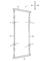
先ず、第1実施形態に係る車載用バッテリフレーム1の概略構成について、図1~図3を参照しつつ詳細に説明する。当該車載用バッテリフレーム1は、フロントフレーム部材10Fと、バックフレーム部材10Bと、一対のサイドフレーム部材20によって枠体状に構成されており、電動機(モータ)を駆動源として走行可能な車両(例えば、ハイブリッド車や電気自動車)に配設されている。
先ず、第1実施形態に係る車載用バッテリフレーム1の概略構成について、図1~図3を参照しつつ詳細に説明する。当該車載用バッテリフレーム1は、フロントフレーム部材10Fと、バックフレーム部材10Bと、一対のサイドフレーム部材20によって枠体状に構成されており、電動機(モータ)を駆動源として走行可能な車両(例えば、ハイブリッド車や電気自動車)に配設されている。
そして、当該車両において、バッテリBが後部座席の下方に配設されており、当該バッテリBには、当該車両の駆動源である電動機へ供給する電力が蓄電されている。当該車載用バッテリフレーム1は、車両の後部座席の下方において、平面視でバッテリBを囲むように配設される(図1、図2参照)。
又、車両の後部座席の下方には、周辺部品PがバッテリBの周囲に配設されている。当該周辺部品Pは、バッテリBから電動機へ電力供給する為の電装部品等を含んでいる。そして、当該車載用バッテリフレーム1は、上述したように、フロントフレーム部材10Fと、バックフレーム部材10Bと、一対のサイドフレーム部材20によって枠体状に構成されているが、車両の構造及び周辺部品Pの配置の関係上、平面視で台形状を為す。
図1~図3に示すように、フロントフレーム部材10Fは、車載用バッテリフレーム1を構成するフレーム部材の一つであり、バッテリBに対して車両前方側に配置される。当該フロントフレーム部材10Fは、断面長方形状を為す角型鋼管により構成されており、本発明に係る第1フレーム部材の一例である。図2に示すように、フロントフレーム部材10Fは、バックフレーム部材10B及びサイドフレーム部材20よりも長く形成されており、長手方向両端部に、第1曲げ部11を夫々有している。第1曲げ部11の詳細については後述する。尚、本発明における長手方向両端部とは、第1フレーム部材(フロントフレーム部材10F、バックフレーム部材10B)の全長の約1/3よりも車幅方向の両外側となる部分のことである。
バックフレーム部材10Bは、車載用バッテリフレーム1を構成するフレーム部材の一つであり、バッテリBに対して車両後方側に配置されている。当該バックフレーム部材10Bは、フロントフレーム部材10Fと同様に、断面長方形状を為す角型鋼管により構成されており、本発明に係る第1フレーム部材の一例である。そして、バックフレーム部材10Bは、サイドフレーム部材20よりも長く、且つ、フロントフレーム部材10Fよりもやや短く形成されており、フロントフレーム部材10Fと同様に、長手方向両端部に、第1曲げ部11を夫々有している。
サイドフレーム部材20は、車載用バッテリフレーム1を構成するフレーム部材の一つであり、バッテリBに対して車両の右側及び左側(即ち、車幅方向外側)に夫々配置されている。各サイドフレーム部材20は、断面長方形状を為す角型鋼管により構成されており、フロントフレーム部材10F及びバックフレーム部材10Bの端部を連結している。各サイドフレーム部材20は、断面長方形状を為す角型鋼管によって、フロントフレーム部材10F及びバックフレーム部材10Bよりも短く形成されている。
当該車載用バッテリフレーム1においては、フロントフレーム部材10Fの各端面は、夫々、サイドフレーム部材20の一側面(枠体の内側となる側面)に接触させた状態で溶接することによって接合される。同様に、バックフレーム部材10Bの各端面は、サイドフレーム部材20の一側面(枠体の内側となる側面)に接触させた状態で溶接することによって接合される。これにより、各サイドフレーム部材20は、フロントフレーム部材10F及びバックフレーム部材10Bの端部を連結する。そして、バッテリBを囲む平面視台形状の枠体としての車載用バッテリフレーム1が形成される。
ここで、第1実施形態に係る車載用バッテリフレーム1においては、フロントフレーム部材10F及びバックフレーム部材10Bは、車幅方向両端部に夫々第1曲げ部11を有している。フロントフレーム部材10F及びバックフレーム部材10Bの各第1曲げ部11は、フロントフレーム部材10F及びバックフレーム部材10Bの端部から、フロントフレーム部材10F及びバックフレーム部材10Bの全長の約1/4となる部分に夫々形成されている。
フロントフレーム部材10Fにおける第1曲げ部11は、フロントフレーム部材10Fにおける車幅方向中央部分に対して、第1曲げ部11よりも車幅方向外側部分を車両前方側へ変位させることで形成され、所定の第1角度αとなるように曲げられる。第1角度αは、フロントフレーム部材10Fにおける車幅方向中央部分と、第1曲げ部11よりも車幅方向外側部分が為す所定角度(例えば、175°~179°)である。これにより、当該フロントフレーム部材10Fの端部は、前記車幅方向外側へ向かう程、前記枠体の外側方向(車両前方側)に位置するように伸びる(図3参照)。
そして、バックフレーム部材10Bにおける第1曲げ部11は、バックフレーム部材10Bにおける車幅方向中央部分に対して、第1曲げ部11よりも車幅方向外側部分を車両後方側へ変位させることで形成され、所定の第1角度αとなるように曲げられる。第1角度αは、バックフレーム部材10Bにおける車幅方向中央部分と、第1曲げ部11よりも車幅方向外側部分が為す所定角度(例えば、175°~179°)である。図3に示すように、当該バックフレーム部材10Bの端部は、前記車幅方向外側へ向かう程、前記枠体の外側方向(車両後方側)に位置するように伸びる。
尚、フロントフレーム部材10F、バックフレーム部材10Bの第1曲げ部11による第1角度αは、車両の側面衝突に伴う衝突荷重Fが作用した場合のサイドフレーム部材20の変位量によって定められる。そして、フロントフレーム部材10Fにおける第1角度αは、バックフレーム部材10Bにおける第1角度αと同じ値としてもよく、異なる値としてもよい。
このように構成された第1実施形態に係る車載用バッテリフレーム1は、フロントフレーム部材10F、バックフレーム部材10B及び一対のサイドフレーム部材20によって構成される枠体状に形成され、バッテリBを囲むように配設される。従って、第1実施形態に係る車載用バッテリフレーム1は、車両の側面衝突によって衝突荷重Fが入力された場合、当該衝突荷重Fによって変形することで、車載用バッテリフレーム1の内側に位置するバッテリBを保護することができる。
(第1実施形態に係る車載用バッテリフレームと、従来例の比較)
次に、第1実施形態に係る車載用バッテリフレーム1と、従来例について、車両の側面衝突に伴う衝突荷重による変形量を、図4、図5を参照しつつ比較する。
尚、以下の説明においては、第1実施形態に係る車載用バッテリフレーム1を、第1例1Aとし、従来の車載用バッテリフレームを、従来例1Pとして説明する。
次に、第1実施形態に係る車載用バッテリフレーム1と、従来例について、車両の側面衝突に伴う衝突荷重による変形量を、図4、図5を参照しつつ比較する。
尚、以下の説明においては、第1実施形態に係る車載用バッテリフレーム1を、第1例1Aとし、従来の車載用バッテリフレームを、従来例1Pとして説明する。
先ず、従来例1Pに相当する車載用バッテリフレームの構成について説明する。従来例1Pを構成する車載用バッテリフレームは、第1実施形態に係る車載用バッテリフレーム1と同様に、角型鋼管からなるフロントフレーム部材10F、バックフレーム部材10B及び一対のサイドフレーム部材20により、平面視台形状の枠体として構成される。
第1例1A(第1実施形態に係る車載用バッテリフレーム1)と、従来例1Pとの相違点は、フロントフレーム部材10F及びバックフレーム部材10Bにおける第1曲げ部11の有無にある。即ち、従来例1Pを構成するフロントフレーム部材10F及びバックフレーム部材10Bは、第1曲げ部11を有しておらず、直線状に伸びる角型鋼管によって構成される。
尚、従来例1Pにおいて、フロントフレーム部材10F及びバックフレーム部材10Bは、第1例1Aにおけるフロントフレーム部材10F及びバックフレーム部材10Bの車幅方向中央部分と同じ位置になるように配設される。従来例1Pにおいて、フロントフレーム部材10F及びバックフレーム部材10Bは、直線状に形成されている為、従来例1Pにおける各サイドフレーム部材20の側面に対し、フロントフレーム部材10F及びバックフレーム部材10Bの端部が接合される位置は、上述した第1例1Aにおける各サイドフレーム部材20に対するフロントフレーム部材10F及びバックフレーム部材10Bの接合位置よりも、枠体の内側方向に位置する(図4参照)。
続いて、このように構成された車載用バッテリフレーム1(従来例1P及び第1例1A)に対して車両の側面衝突に伴って衝突荷重Fが作用した場合の各フレーム部材の変形態様について説明する。尚、以下の説明においては、車両の左側面に対する側面衝突によって、車両の左側から衝突荷重Fが入力された場合を例として挙げて説明する。
車両左側から衝突荷重Fが入力された場合、車両左側のサイドフレーム部材20は、衝突荷重Fに伴って撓み、車載用バッテリフレーム1に係る枠体の内側方向へ変位する。車両左側のサイドフレーム部材20が枠体の内側方向に変位することによって、当該車載用バッテリフレーム1のフロントフレーム部材10Fは、両側のサイドフレーム部材20の間で、衝突荷重Fによって圧縮される。これにより、車載用バッテリフレーム1のフロントフレーム部材10Fは、衝突荷重Fによって変形し、車幅方向中央部分が車両前方側へ変位する。
同様に、車両左側のサイドフレーム部材20が枠体の内側方向に変位することで、当該車載用バッテリフレーム1のバックフレーム部材10Bは、両側のサイドフレーム部材20の間で、衝突荷重Fによって圧縮される。これにより、車載用バッテリフレーム1のバックフレーム部材10Bは、衝突荷重Fによって変形し、車幅方向中央部分が車両後方側へ変位する。
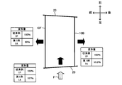
続いて、車両左側からの側面衝突によって、所定の大きさの衝突荷重Fが作用した場合の従来例1Pにおける各フレーム部材の変形量と、第1例1A(第1実施形態)における各フレーム部材の変形量との比較について、図5を参照しつつ説明する。尚、以下の説明においては、従来例1Pに係る各フレーム部材の変形量を100%として、第1例1Aにおける各フレーム部材の変形量との比較を行う。
図5に示すように、第1例1Aにおける車載用バッテリフレーム1に対して、車両左側から所定の大きさの衝突荷重Fが入力された場合、第1例1Aにおけるサイドフレーム部材20の変形量は、従来例1Pを100%とした場合に107%を示し、従来例1Pと比較して7%増大している。この点、第1例1Aにおけるサイドフレーム部材20の変形量の増大が7%程度であれば、車載用バッテリフレーム1内側に位置するバッテリBに、当該サイドフレーム部材20が接触することはなく、車載用バッテリフレーム1によってバッテリBを保護し得る。
そして、車載用バッテリフレーム1に対して、車両左側から所定の大きさの衝突荷重Fが入力された場合、第1例1Aにおけるフロントフレーム部材10Fの変形量は、従来例1Pを100%とした場合に50%を示し、従来例1Pと比較して50%低減される。この点、第1例1Aにおけるフロントフレーム部材10Fの変形量が50%に低減される為、第1例1A(第1実施形態)に係る車載用バッテリフレーム1によれば、側面衝突によって、フロントフレーム部材10Fが車両前方側に向かって変形し周辺部品Pと接触する可能性を低減することができ、もって、周辺部品Pの破損を防止することができる。
一方、車両左側から所定の大きさの衝突荷重Fが入力された場合、第1例1Aにおけるバックフレーム部材10Bの変形量は、従来例1Pを100%とした場合に約55.5%を示し、従来例1Pと比較して約44.5%低減される。つまり、第1例1Aにおけるバックフレーム部材10Bの変形量が約55.5%に低減される為、第1例1A(第1実施形態)に係る車載用バッテリフレーム1によれば、側面衝突によって、バックフレーム部材10Bが車両後方側に向かって変形し周辺部品Pと接触する可能性を低減することができ、もって、周辺部品Pの破損を防止することができる。
以上説明したように、第1実施形態に係る車載用バッテリフレーム1は、フロントフレーム部材10Fと、バックフレーム部材10Bと、一対のサイドフレーム部材20とを有する平面視台形状を為す枠体として構成され、バッテリBが当該枠体の内側に位置するように配設される(図2参照)。従って、当該車載用バッテリフレーム1によれば、図5に示すように、当該車載用バッテリフレーム1が、車両の側面衝突に伴う衝突荷重Fを受けることで、枠体内部に配置されたバッテリBを、衝突荷重Fから保護することができる。
そして、第1実施形態に係る車載用バッテリフレーム1において、フロントフレーム部材10Fは、第1曲げ部11を有しており、当該フロントフレーム部材10Fの車幅方向両端部は、第1曲げ部11によって第1角度αで曲げられることで、車幅方向外側へ向かう程、車両前方側に位置する。又、バックフレーム部材10Bも、第1曲げ部11を有しており、当該バックフレーム部材10Bの車幅方向両端部は、第1曲げ部11によって第1角度αで曲げられることで、車幅方向外側へ向かう程、車両後方側に位置する。
図5に示すように、第1実施形態に係る車載用バッテリフレーム1によれば、フロントフレーム部材10F及びバックフレーム部材10Bの車幅方向両端部に、第1曲げ部11を形成することによって、車両の側面衝突に係る衝突荷重Fが入力された場合のフロントフレーム部材10F及びバックフレーム部材10Bの変形量を、従来例1Pの約50%に抑制することができる。これにより、当該車載用バッテリフレーム1は、バッテリB及び周辺部品Pに対する車載用バッテリフレーム1の接触を抑制し、周辺部品Pの損傷を防止し得る。又、当該車載用バッテリフレーム1は、フロントフレーム部材10F及びバックフレーム部材10Bに、第1曲げ部11を夫々形成するだけで、周辺部品Pの損傷防止性能を高めることができ、コストの増大を招くことなく、より高性能な車載用バッテリフレーム1を提供し得る。
図1に示すように、第1実施形態において、フロントフレーム部材10F、バックフレーム部材10B及び一対のサイドフレーム部材20は、角型鋼管によって構成され、車載用バッテリフレーム1は、フロントフレーム部材10F及びバックフレーム部材10Bの端面を、サイドフレーム部材20の側面に突き合せて溶接接合することによって構成されている為、側面衝突に対するバッテリBの保護と、周辺部品Pの損傷防止とを両立可能な車載用バッテリフレーム1を、シンプルな構成で安価に製造し得る。
(第2実施形態)
次に、側面衝突に伴うフロントフレーム部材10F及びバックフレーム部材10Bの変形量をより効果的に抑制する為になされた上述した第1実施形態と異なる実施形態(第2実施形態)について、図面を参照しつつ詳細に説明する。
次に、側面衝突に伴うフロントフレーム部材10F及びバックフレーム部材10Bの変形量をより効果的に抑制する為になされた上述した第1実施形態と異なる実施形態(第2実施形態)について、図面を参照しつつ詳細に説明する。
(第2実施形態に係る車載用バッテリフレームの概略構成)
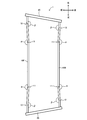
先ず、第2実施形態に係る車載用バッテリフレーム1の概略構成について、図6~図8を参照しつつ詳細に説明する。尚、第2実施形態に係る車載用バッテリフレーム1は、フロントフレーム部材10F、バックフレーム部材10Bの構成を除き、上述した第1実施形態に係る車載用バッテリフレーム1と同様の基本的構成を有している。従って、以下の説明においては、第1実施形態と同様の構成についての説明を省略し、相違する構成について詳細に説明する。
先ず、第2実施形態に係る車載用バッテリフレーム1の概略構成について、図6~図8を参照しつつ詳細に説明する。尚、第2実施形態に係る車載用バッテリフレーム1は、フロントフレーム部材10F、バックフレーム部材10Bの構成を除き、上述した第1実施形態に係る車載用バッテリフレーム1と同様の基本的構成を有している。従って、以下の説明においては、第1実施形態と同様の構成についての説明を省略し、相違する構成について詳細に説明する。
図6~図8に示すように、第2実施形態に係る車載用バッテリフレーム1は、第1実施形態と同様に、フロントフレーム部材10Fと、バックフレーム部材10Bと、一対のサイドフレーム部材20によって枠体状に構成されており、電動機(モータ)を駆動源として走行可能な車両(例えば、ハイブリッド車や電気自動車)に配設されている。そして、第2実施形態に係る車載用バッテリフレーム1において、一対のサイドフレーム部材20は、断面長方形状を為す角型鋼管によって、第1実施形態に係るサイドフレーム部材20と同様に構成されている。
ここで、第2実施形態に係るフロントフレーム部材10Fは、第1実施形態と同様に、断面長方形状を為す角型鋼管によって構成され、バッテリBに対して車両前方側に配置される。そして、第2実施形態に係るフロントフレーム部材10Fは、第1実施形態と同様の位置に、第1角度αで曲げた第1曲げ部11を有している。第2実施形態に係るフロントフレーム部材10Fの第1角度αも、第1実施形態と同様に、車両の側面衝突に伴う衝突荷重Fが作用した場合のサイドフレーム部材20の変位量によって定められ、例えば、175°~179°といった値をとる。
第2実施形態に係るフロントフレーム部材10Fは、第1実施形態と異なり、当該第1曲げ部11よりも車幅方向外側に、第2曲げ部12を夫々有している。第2実施形態に係るフロントフレーム部材10Fにおいて、第2曲げ部12は、フロントフレーム部材10Fの端部から、フロントフレーム部材10Fの全長の約1/12となる部分に夫々形成されている。
第2実施形態に係るフロントフレーム部材10Fにおいて、第2曲げ部12は、当該フロントフレーム部材10Fにおける第1曲げ部11と第2曲げ部12の間となる部分に対して、第2曲げ部12よりも車幅方向外側部分を車両後方側へ変位させることで形成され、所定の第2角度βとなるように曲げられる。第2角度βは、第1曲げ部11と第2曲げ部12の間となる部分と、第2曲げ部12よりも車幅方向外側部分が為す角度である。第2角度βの大きさは、第1曲げ部11における第1角度αと同程度(例えば、175°~179°)であり、同一の値が望ましい。これにより、当該フロントフレーム部材10Fの端部は、前記第1曲げ部11と前記第2曲げ部12の間における前記フロントフレーム部材10Fの伸びる向きに対して、第2曲げ部12よりも前記車幅方向外側へ向かう程、前記枠体の内側(車両後方側)方向に伸びている(図8参照)。
そして、第2実施形態に係るバックフレーム部材10Bは、断面長方形状を為す角型鋼管によって構成され、バッテリBに対して車両後方側に配置される。そして、第2実施形態に係るバックフレーム部材10Bは、第1実施形態と同様の位置に、第1角度αで曲げた第1曲げ部11を有している。第2実施形態に係るバックフレーム部材10Bの第1角度αも、第1実施形態と同様に、車両の側面衝突に伴う衝突荷重Fが作用した場合のサイドフレーム部材20の変位量によって定められ、例えば、175°~179°といった値をとる。
第2実施形態に係るバックフレーム部材10Bは、フロントフレーム部材10Fと同様に、当該第1曲げ部11よりも車幅方向外側に、第2曲げ部12を夫々有している。第2実施形態に係るバックフレーム部材10Bにおいて、各第2曲げ部12は、バックフレーム部材10Bの端部から、バックフレーム部材10Bの全長の約1/12となる部分に夫々形成されている。
そして、第2実施形態に係るバックフレーム部材10Bにおいて、第2曲げ部12は、当該バックフレーム部材10Bにおける第1曲げ部11と第2曲げ部12の間となる部分に対して、第2曲げ部12よりも車幅方向外側部分を車両前方側へ変位させることで形成され、所定の第2角度βとなるように曲げられる。第2角度βは、第1曲げ部11と第2曲げ部12の間となる部分と、第2曲げ部12よりも車幅方向外側部分が為す角度を示している。第2角度βの大きさは、第1曲げ部11における第1角度αと同程度(例えば、175°~179°)であり、同一の値が望ましい。図8に示すように、当該バックフレーム部材10Bの端部は、前記第1曲げ部11と前記第2曲げ部12の間における前記バックフレーム部材10Bの伸びる向きに対して、第2曲げ部12よりも前記車幅方向外側へ向かう程、前記枠体の内側(車両前方側)となる方向に伸びている。
図6~図8に示すように、第2実施形態に係る車載用バッテリフレーム1は、フロントフレーム部材10F、バックフレーム部材10B及び一対のサイドフレーム部材20によって構成される枠体状に形成され、バッテリBを囲むように配設される。従って、第2実施形態に係る車載用バッテリフレーム1は、第1実施形態と同様に、車両の側面衝突によって衝突荷重Fが入力された場合、当該衝突荷重Fによって変形することで、車載用バッテリフレーム1の内側に位置するバッテリBを保護することができる。
(第2実施形態に係る車載用バッテリフレームと、従来例及び第1実施形態との比較)
続いて、第2実施形態に係る車載用バッテリフレーム1と、第1実施形態に係る車載用バッテリフレーム1及び従来例について、車両の側面衝突に伴う衝突荷重Fによる変形量を、図9、図10を参照しつつ比較する。
尚、以下の説明においては、第2実施形態に係る車載用バッテリフレーム1を、第2例1Bとして説明する。そして、第1実施形態と同様に、第1実施形態に係る車載用バッテリフレーム1を、第1例1Aとし、従来の車載用バッテリフレームを、従来例1Pとして説明する。
続いて、第2実施形態に係る車載用バッテリフレーム1と、第1実施形態に係る車載用バッテリフレーム1及び従来例について、車両の側面衝突に伴う衝突荷重Fによる変形量を、図9、図10を参照しつつ比較する。
尚、以下の説明においては、第2実施形態に係る車載用バッテリフレーム1を、第2例1Bとして説明する。そして、第1実施形態と同様に、第1実施形態に係る車載用バッテリフレーム1を、第1例1Aとし、従来の車載用バッテリフレームを、従来例1Pとして説明する。
図9に示すように、第2例1B(第2実施形態)において、フロントフレーム部材10F及びバックフレーム部材10Bは、その車幅方向中央部分が従来例1P及び第1例1Aに係るフロントフレーム部材10F及びバックフレーム部材10Bの車幅中央部分と同じ位置になるように配設される。そして、第2例1Bにおけるフロントフレーム部材10F及びバックフレーム部材10Bの端部は、第1例1Aにおけるフロントフレーム部材10F及びバックフレーム部材10Bと同じ位置関係で、各サイドフレーム部材20に接合されている。
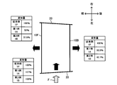
続いて、このように構成された車載用バッテリフレーム1(従来例1P、第1例1A及び第2例1B)に対して、車両左側からの側面衝突によって衝突荷重Fが作用した場合の各フレーム部材の変形量との比較について、図10を参照しつつ説明する。尚、以下の説明においては、第1実施形態と同様に、従来例1Pに係る各フレーム部材の変形量を100%として、第1例1A及び第2例1Bにおける各フレーム部材の変形量の比較を行う。
図10に示すように、第2例1Bに係る車載用バッテリフレーム1に対して、車両左側から衝突荷重Fが入力された場合、サイドフレーム部材20は、衝突荷重Fによって枠体内側へ向かって変位する。この場合、第2例1Bに係るサイドフレーム部材20の変形量は、従来例1Pを100%とした場合に108%を示し、従来例1Pと比較して8%増大している。第1例1Aにおけるサイドフレーム部材20の変形量は107%である為、第2例1Bにおけるサイドフレーム部材20の変形量は、第1例1Aと大きな差はない。
第2例1Bにおけるサイドフレーム部材20の変形量の増大が8%程度であれば、第1例1Aと同様に、車載用バッテリフレーム1内側に位置するバッテリBに、当該サイドフレーム部材20が接触することはなく、車載用バッテリフレーム1によってバッテリBを保護し得る。
車載用バッテリフレーム1に対して、車両左側から衝突荷重Fが入力された場合、当該車載用バッテリフレーム1のフロントフレーム部材10Fは、両側のサイドフレーム部材20の間で、衝突荷重Fによって圧縮される。第2例1Bにおけるフロントフレーム部材10Fには、第1曲げ部11及び第2曲げ部12が形成されているので、衝突荷重Fは、フロントフレーム部材10Fを車両前方側へ変形させるよりも、第1曲げ部11及び第2曲げ部12における曲げを促進するように作用し、車両前方側への変形量を抑制する。
図10に示す解析結果からもわかるように、第2例1Bに係るフロントフレーム部材10Fの変形量は、従来例1Pを100%とした場合に37.5%を示し、従来例1Pと比較して62.5%低減される。第1例1Aにおけるフロントフレーム部材10Fの変形量は50%である為、第2例1Bにおけるフロントフレーム部材10Fの変形量は、第1例1Aと比較しても低減されている。
即ち、車載用バッテリフレーム1を構成するフロントフレーム部材10Fに対して、第1曲げ部11及び第2曲げ部12を形成することによって、側面衝突による衝突荷重Fが作用した場合のフロントフレーム部材10Fの変形量を低減し得る。これにより、第2例1B(第2実施形態)に係る車載用バッテリフレーム1によれば、側面衝突によってフロントフレーム部材10Fが車両前方側に向かって変形し、周辺部品Pと接触する可能性を低減することができ、もって、周辺部品Pの破損を防止することができる。
一方、車両左側から衝突荷重Fが入力された場合、当該車載用バッテリフレーム1のバックフレーム部材10Bは、両側のサイドフレーム部材20の間で、衝突荷重Fによって圧縮される。第2例1Bにおけるバックフレーム部材10Bにおいても、第1曲げ部11及び第2曲げ部12が形成されているので、衝突荷重Fは、バックフレーム部材10Bを車両後方側へ変形させるよりも、第1曲げ部11及び第2曲げ部12における曲げを促進するように作用し、車両後方側への変形量を抑制する。
第2例1Bにおけるバックフレーム部材10Bの変形量は、従来例1Pを100%とした場合に約42.7%を示し、従来例1Pと比較して約57.3%低減される(図10参照)。そして、第1例1Aにおけるバックフレーム部材10Bの変形量は約55.5%である為、第2例1Bにおけるバックフレーム部材10Bの変形量は、第1例1Aと比較しても低減されている。
上述したフロントフレーム部材10Fと同様に、車載用バッテリフレーム1を構成するバックフレーム部材10Bに対して、第1曲げ部11及び第2曲げ部12を形成することによって、側面衝突による衝突荷重Fが作用した場合のバックフレーム部材10Bの変形量を低減し得る。これにより、第2例1B(第2実施形態)に係る車載用バッテリフレーム1によれば、側面衝突によってバックフレーム部材10Bが車両後方側に向かって変形し、周辺部品Pと接触する可能性を低減することができ、もって、周辺部品Pの破損を防止することができる。
以上説明したように、第2実施形態に係る車載用バッテリフレーム1は、第1実施形態と同様に、フロントフレーム部材10Fと、バックフレーム部材10Bと、一対のサイドフレーム部材20とを有する平面視台形状を為す枠体として構成され、バッテリBが当該枠体の内側に位置するように配設される(図7参照)。従って、当該車載用バッテリフレーム1によれば、図10に示すように、当該車載用バッテリフレーム1が、車両の側面衝突に伴う衝突荷重Fを受けることで、枠体内部に配置されたバッテリBを、衝突荷重Fから保護することができる。
第2実施形態に係る車載用バッテリフレーム1において、フロントフレーム部材10Fは、第1実施形態と同様に、第1曲げ部11を有しており、第1曲げ部11によって第1角度αで曲げられることで、車幅方向外側へ向かう程、車両前方側に位置する。又、バックフレーム部材10Bも、第1実施形態と同様に、第1曲げ部11を有しており、第1曲げ部11によって第1角度αで曲げられることで、車幅方向外側へ向かう程、車両後方側に位置する。
更に、第2実施形態に係るフロントフレーム部材10Fは、第1曲げ部11よりも車幅方向外側に、第2曲げ部12を夫々有しており、第2曲げ部12によって第2角度βで曲げられることで、前記第1曲げ部11と前記第2曲げ部12の間における前記フロントフレーム部材10Fの伸びる向きに対して、第2曲げ部12よりも前記車幅方向外側へ向かう程、前記枠体の内側方向(車両後方側)に位置する。又、バックフレーム部材10Bも、第1曲げ部11よりも車幅方向外側に、第2曲げ部12を夫々有しており、第2曲げ部12によって第2角度βで曲げられることで、前記第1曲げ部11と前記第2曲げ部12の間における前記バックフレーム部材10Bの伸びる向きに対して、第2曲げ部12よりも前記車幅方向外側へ向かう程、前記枠体の内側方向(車両前方側)に位置する。
図10に示すように、第2実施形態に係る車載用バッテリフレーム1によれば、フロントフレーム部材10F及びバックフレーム部材10Bの車幅方向両端部に、第1曲げ部11及び第2曲げ部12を形成することによって、車両の側面衝突に係る衝突荷重Fが入力された場合のフロントフレーム部材10F及びバックフレーム部材10Bの変形量を、従来例1Pの約40%程度に抑制することができる。これにより、当該車載用バッテリフレーム1は、バッテリB及び周辺部品Pに対する車載用バッテリフレーム1の接触を抑制し、周辺部品Pの損傷を防止し得る。又、当該車載用バッテリフレーム1は、フロントフレーム部材10F及びバックフレーム部材10Bに、第1曲げ部11に加えて、第2曲げ部12を夫々形成するだけで、周辺部品Pの損傷防止性能を更に高めることができ、コストの増大を招くことなく、より高性能な車載用バッテリフレーム1を提供し得る。
図6に示すように、第2実施形態においても、フロントフレーム部材10F、バックフレーム部材10B及び一対のサイドフレーム部材20は、角型鋼管によって構成され、車載用バッテリフレーム1は、フロントフレーム部材10F及びバックフレーム部材10Bの端面を、サイドフレーム部材20の側面に突き合せて溶接接合することによって構成されている。従って、第2実施形態に係る車載用バッテリフレーム1によれば、側面衝突に対するバッテリBの保護と、周辺部品Pの損傷防止との両立を、更に高度に実現可能な車載用バッテリフレーム1を、シンプルな構成で且つ安価に製造し得る。
以上、実施形態に基づき本発明を説明したが、本発明は上述した実施形態に何ら限定されるものではなく、本発明の趣旨を逸脱しない範囲内で種々の改良変更が可能である。例えば、上述した実施形態においては、フロントフレーム部材10F、バックフレーム部材10B及びサイドフレーム部材20を、角型鋼管により構成していたが、この態様に限定されるものではない。フロントフレーム部材10F、バックフレーム部材10B及びサイドフレーム部材20を、他の断面形状を有する鋼管(例えば、丸型鋼管)によって構成することも可能であり、リップ溝形鋼やチャンネル鋼等の鋼材によって構成することも可能である。
又、上述した実施形態においては、車載用バッテリフレーム1は、周辺部品P等との関係上、平面視、台形状となるように構成されていたが、この態様に限定されるものではない。車載用バッテリフレーム1は、フロントフレーム部材10F、バックフレーム部材10B及び一対のサイドフレーム部材20により枠体として構成されていればよく、平面視で長方形状を為すように接合されていてもよい。
そして、上述した実施形態においては、フロントフレーム部材10F、バックフレーム部材10Bは、サイドフレーム部材20よりも十分に長く形成されていたが、この態様に限定されるものではない。例えば、フロントフレーム部材10F、バックフレーム部材10Bが、サイドフレーム部材20と同じ若しくはやや長く形成されていてもよい。又、フロントフレーム部材10F、バックフレーム部材10B、サイドフレーム部材20の長さが何れも同程度である場合には、本発明は、サイドフレーム部材20をやや長く形成しても効果を発揮し得る。
又、フロントフレーム部材10Fの第1曲げ部11における第1角度αは、バックフレーム部材10Bの第1曲げ部11における第1角度αと同じであってもよいし、相違する構成であってもよい。そして、或る第1フレーム部材(フロントフレーム部材10F又はバックフレーム部材10B)において、第1曲げ部11の第1角度αは、第2曲げ部12の第2角度βと同じ角度であってもよいし、第1角度αと第2角度βが相違していてもよい。
そして、上述した実施形態においては、車載用バッテリフレーム1を構成する際に、フロントフレーム部材10F及びバックフレーム部材10Bの端面を、各サイドフレーム部材20の側面に接触させた状態で溶接することによって接合したが、この態様に限定されるものではない。フロントフレーム部材10F、バックフレーム部材10B、サイドフレーム部材20の各端部を斜めに切り落とした端面同士を接触させて溶接することも可能である。又、各フレーム部材の接合方法も、溶接に限定されるものではなく、フロントフレーム部材10F、バックフレーム部材10B、サイドフレーム部材20を、所定以上の強度で接合することができれば、種々の態様を採用し得る。
1 車載用バッテリフレーム
10F フロントフレーム部材
10B バックフレーム部材
11 第1曲げ部
12 第2曲げ部
20 サイドフレーム部材
B バッテリ
P 周辺部品
F 衝突荷重
α 第1角度
β 第2角度
10F フロントフレーム部材
10B バックフレーム部材
11 第1曲げ部
12 第2曲げ部
20 サイドフレーム部材
B バッテリ
P 周辺部品
F 衝突荷重
α 第1角度
β 第2角度
Claims (3)
- 車両に搭載されたバッテリに対して車両前方側及び車両後方側となる位置に夫々配置され、前記車両の車幅方向に伸びる一対の第1フレーム部材と、
前記バッテリに対して車幅方向外側となる位置に夫々配置され、前記一対の第1フレーム部材の端部を連結する一対の第2フレーム部材と、を有する枠体として構成され、前記バッテリが当該枠体の内側に位置するように前記車体に支持される車載用バッテリフレームであって、
前記第1フレーム部材は、
前記第2フレーム部材以上の長さで形成され、
前記車幅方向外側へ向かう程、前記枠体の外側方向に位置するように、所定の第1角度で曲げた第1曲げ部を、車幅方向両端部に有する
ことを特徴とする車載用バッテリフレーム。 - 前記第1フレーム部材は、
所定の第2角度で曲げた第2曲げ部を、前記第1曲げ部よりも車幅方向外側に有し、
前記第2曲げ部は、
前記第1曲げ部と前記第2曲げ部の間における前記第1フレーム部材の伸びる向きに対して、前記車幅方向外側へ向かうほど、前記枠体の内側となる向きに、前記第1フレーム部材を曲げて構成されている
ことを特徴とする請求項1記載の車載用バッテリフレーム。 - 前記第1フレーム部材及び前記第2フレーム部材は、鋼管によって構成され、
前記車載用バッテリフレームは、前記第1フレーム部材の端部と前記第2フレーム部材の端部同士を接合することによって構成されている
ことを特徴とする請求項1又は請求項2記載の車載用バッテリフレーム。
Priority Applications (1)
| Application Number | Priority Date | Filing Date | Title |
|---|---|---|---|
| US15/551,577 US20180043763A1 (en) | 2015-02-18 | 2015-10-14 | Battery mounting frame |
Applications Claiming Priority (2)
| Application Number | Priority Date | Filing Date | Title |
|---|---|---|---|
| JP2015-029466 | 2015-02-18 | ||
| JP2015029466A JP6227575B2 (ja) | 2015-02-18 | 2015-02-18 | 車載用バッテリフレーム |
Publications (1)
| Publication Number | Publication Date |
|---|---|
| WO2016132593A1 true WO2016132593A1 (ja) | 2016-08-25 |
Family
ID=56688873
Family Applications (1)
| Application Number | Title | Priority Date | Filing Date |
|---|---|---|---|
| PCT/JP2015/079017 Ceased WO2016132593A1 (ja) | 2015-02-18 | 2015-10-14 | 車載用バッテリフレーム |
Country Status (3)
| Country | Link |
|---|---|
| US (1) | US20180043763A1 (ja) |
| JP (1) | JP6227575B2 (ja) |
| WO (1) | WO2016132593A1 (ja) |
Families Citing this family (4)
| Publication number | Priority date | Publication date | Assignee | Title |
|---|---|---|---|---|
| FR3082453B1 (fr) | 2018-06-13 | 2020-07-17 | Psa Automobiles Sa | Coupelle de suspension assurant une protection de la batterie pour un vehicule hybride ou electrique |
| WO2021123881A1 (en) * | 2019-12-18 | 2021-06-24 | Arcelormittal | Reinforcement frame for a battery pack of an electric or hybrid vehicle, reinforced battery pack and process for assembling said battery pack |
| KR102939183B1 (ko) | 2020-11-12 | 2026-03-12 | 현대자동차주식회사 | 고전압배터리가 구비된 차체 |
| CN119018245B (zh) * | 2024-08-22 | 2025-09-12 | 重庆长安汽车股份有限公司 | 一种门槛边梁及车辆 |
Citations (7)
| Publication number | Priority date | Publication date | Assignee | Title |
|---|---|---|---|---|
| JP2009190523A (ja) * | 2008-02-13 | 2009-08-27 | Nissan Motor Co Ltd | 車両の水素タンク搭載構造 |
| JP2011152841A (ja) * | 2010-01-27 | 2011-08-11 | Mazda Motor Corp | 車両の前部車体構造 |
| JP2013014312A (ja) * | 2011-06-07 | 2013-01-24 | Toyota Auto Body Co Ltd | 自動車後部における重要保安部品の設置構造 |
| JP2013199196A (ja) * | 2012-03-26 | 2013-10-03 | Suzuki Motor Corp | 電気自動車のバッテリパック搭載構造 |
| JP2013214534A (ja) * | 2010-12-15 | 2013-10-17 | Mitsubishi Motors Corp | バッテリケース |
| JP2014104976A (ja) * | 2012-11-29 | 2014-06-09 | Audi Ag | 自動車のサブフレーム |
| JP2014522774A (ja) * | 2011-07-08 | 2014-09-08 | ティッセンクルップ スチール ヨーロッパ アクチェンゲゼルシャフト | 車両の床構造 |
-
2015
- 2015-02-18 JP JP2015029466A patent/JP6227575B2/ja active Active
- 2015-10-14 US US15/551,577 patent/US20180043763A1/en not_active Abandoned
- 2015-10-14 WO PCT/JP2015/079017 patent/WO2016132593A1/ja not_active Ceased
Patent Citations (7)
| Publication number | Priority date | Publication date | Assignee | Title |
|---|---|---|---|---|
| JP2009190523A (ja) * | 2008-02-13 | 2009-08-27 | Nissan Motor Co Ltd | 車両の水素タンク搭載構造 |
| JP2011152841A (ja) * | 2010-01-27 | 2011-08-11 | Mazda Motor Corp | 車両の前部車体構造 |
| JP2013214534A (ja) * | 2010-12-15 | 2013-10-17 | Mitsubishi Motors Corp | バッテリケース |
| JP2013014312A (ja) * | 2011-06-07 | 2013-01-24 | Toyota Auto Body Co Ltd | 自動車後部における重要保安部品の設置構造 |
| JP2014522774A (ja) * | 2011-07-08 | 2014-09-08 | ティッセンクルップ スチール ヨーロッパ アクチェンゲゼルシャフト | 車両の床構造 |
| JP2013199196A (ja) * | 2012-03-26 | 2013-10-03 | Suzuki Motor Corp | 電気自動車のバッテリパック搭載構造 |
| JP2014104976A (ja) * | 2012-11-29 | 2014-06-09 | Audi Ag | 自動車のサブフレーム |
Also Published As
| Publication number | Publication date |
|---|---|
| JP2016150682A (ja) | 2016-08-22 |
| JP6227575B2 (ja) | 2017-11-08 |
| US20180043763A1 (en) | 2018-02-15 |
Similar Documents
| Publication | Publication Date | Title |
|---|---|---|
| US9555756B2 (en) | Vehicle front structure | |
| JP6215905B2 (ja) | 車体後部構造 | |
| CN103895720B (zh) | 多用途车辆 | |
| US9415808B2 (en) | Vehicle front section structure | |
| JP5508543B2 (ja) | 車両のケーブル配設構造 | |
| CN105102312B (zh) | 车身前部结构以及载荷承受部件 | |
| US20150360548A1 (en) | Mounting frame for an electrically driven motor vehicle | |
| US20150246651A1 (en) | Vehicle front section structure | |
| JP6227575B2 (ja) | 車載用バッテリフレーム | |
| JP4924665B2 (ja) | 車体の後部構造 | |
| JP5790365B2 (ja) | 車両用バッテリ搭載構造 | |
| WO2009139229A1 (ja) | 電源装置の保護構造 | |
| JP5405506B2 (ja) | バッテリ支持構造 | |
| WO2012014776A1 (ja) | 車体の下部構造 | |
| JP2013103590A (ja) | 電気自動車の前部車体構造 | |
| CN105539592A (zh) | 车辆的车身前部结构 | |
| CN105683026A (zh) | 汽车的车体构造 | |
| JP6452044B2 (ja) | 自動車の後部車体構造 | |
| JP6137105B2 (ja) | 車両駆動用バッテリの取付構造 | |
| WO2016063967A1 (ja) | 保護フレーム構造体 | |
| JP6035990B2 (ja) | 車両用電源装置 | |
| JP2015039890A (ja) | バッテリ搭載構造 | |
| JP2015116979A (ja) | 車体下部構造 | |
| KR101647564B1 (ko) | 차량 전부 구조 | |
| JP5832508B2 (ja) | 車体フレーム構造 |
Legal Events
| Date | Code | Title | Description |
|---|---|---|---|
| 121 | Ep: the epo has been informed by wipo that ep was designated in this application |
Ref document number: 15882694 Country of ref document: EP Kind code of ref document: A1 |
|
| WWE | Wipo information: entry into national phase |
Ref document number: 15551577 Country of ref document: US |
|
| NENP | Non-entry into the national phase |
Ref country code: DE |
|
| 122 | Ep: pct application non-entry in european phase |
Ref document number: 15882694 Country of ref document: EP Kind code of ref document: A1 |