WO2016132502A1 - 溶接装置、溶接方法、及びタービン翼 - Google Patents
溶接装置、溶接方法、及びタービン翼 Download PDFInfo
- Publication number
- WO2016132502A1 WO2016132502A1 PCT/JP2015/054585 JP2015054585W WO2016132502A1 WO 2016132502 A1 WO2016132502 A1 WO 2016132502A1 JP 2015054585 W JP2015054585 W JP 2015054585W WO 2016132502 A1 WO2016132502 A1 WO 2016132502A1
- Authority
- WO
- WIPO (PCT)
- Prior art keywords
- powder
- nozzle
- welding
- shield
- gas
- Prior art date
- Legal status (The legal status is an assumption and is not a legal conclusion. Google has not performed a legal analysis and makes no representation as to the accuracy of the status listed.)
- Ceased
Links
Images





Classifications
-
- B—PERFORMING OPERATIONS; TRANSPORTING
- B23—MACHINE TOOLS; METAL-WORKING NOT OTHERWISE PROVIDED FOR
- B23K—SOLDERING OR UNSOLDERING; WELDING; CLADDING OR PLATING BY SOLDERING OR WELDING; CUTTING BY APPLYING HEAT LOCALLY, e.g. FLAME CUTTING; WORKING BY LASER BEAM
- B23K26/00—Working by laser beam, e.g. welding, cutting or boring
- B23K26/14—Working by laser beam, e.g. welding, cutting or boring using a fluid stream, e.g. a jet of gas, in conjunction with the laser beam; Nozzles therefor
- B23K26/144—Working by laser beam, e.g. welding, cutting or boring using a fluid stream, e.g. a jet of gas, in conjunction with the laser beam; Nozzles therefor the fluid stream containing particles, e.g. powder
-
- B—PERFORMING OPERATIONS; TRANSPORTING
- B05—SPRAYING OR ATOMISING IN GENERAL; APPLYING FLUENT MATERIALS TO SURFACES, IN GENERAL
- B05B—SPRAYING APPARATUS; ATOMISING APPARATUS; NOZZLES
- B05B7/00—Spraying apparatus for discharge of liquids or other fluent materials from two or more sources, e.g. of liquid and air, of powder and gas
- B05B7/16—Spraying apparatus for discharge of liquids or other fluent materials from two or more sources, e.g. of liquid and air, of powder and gas incorporating means for heating or cooling the material to be sprayed
- B05B7/22—Spraying apparatus for discharge of liquids or other fluent materials from two or more sources, e.g. of liquid and air, of powder and gas incorporating means for heating or cooling the material to be sprayed electrically, magnetically or electromagnetically, e.g. by arc
- B05B7/228—Spraying apparatus for discharge of liquids or other fluent materials from two or more sources, e.g. of liquid and air, of powder and gas incorporating means for heating or cooling the material to be sprayed electrically, magnetically or electromagnetically, e.g. by arc using electromagnetic radiation, e.g. laser
-
- B—PERFORMING OPERATIONS; TRANSPORTING
- B23—MACHINE TOOLS; METAL-WORKING NOT OTHERWISE PROVIDED FOR
- B23K—SOLDERING OR UNSOLDERING; WELDING; CLADDING OR PLATING BY SOLDERING OR WELDING; CUTTING BY APPLYING HEAT LOCALLY, e.g. FLAME CUTTING; WORKING BY LASER BEAM
- B23K26/00—Working by laser beam, e.g. welding, cutting or boring
- B23K26/14—Working by laser beam, e.g. welding, cutting or boring using a fluid stream, e.g. a jet of gas, in conjunction with the laser beam; Nozzles therefor
- B23K26/1462—Nozzles; Features related to nozzles
- B23K26/1464—Supply to, or discharge from, nozzles of media, e.g. gas, powder, wire
-
- B—PERFORMING OPERATIONS; TRANSPORTING
- B23—MACHINE TOOLS; METAL-WORKING NOT OTHERWISE PROVIDED FOR
- B23K—SOLDERING OR UNSOLDERING; WELDING; CLADDING OR PLATING BY SOLDERING OR WELDING; CUTTING BY APPLYING HEAT LOCALLY, e.g. FLAME CUTTING; WORKING BY LASER BEAM
- B23K26/00—Working by laser beam, e.g. welding, cutting or boring
- B23K26/34—Laser welding for purposes other than joining
-
- B—PERFORMING OPERATIONS; TRANSPORTING
- B23—MACHINE TOOLS; METAL-WORKING NOT OTHERWISE PROVIDED FOR
- B23K—SOLDERING OR UNSOLDERING; WELDING; CLADDING OR PLATING BY SOLDERING OR WELDING; CUTTING BY APPLYING HEAT LOCALLY, e.g. FLAME CUTTING; WORKING BY LASER BEAM
- B23K26/00—Working by laser beam, e.g. welding, cutting or boring
- B23K26/34—Laser welding for purposes other than joining
- B23K26/342—Build-up welding
-
- F—MECHANICAL ENGINEERING; LIGHTING; HEATING; WEAPONS; BLASTING
- F01—MACHINES OR ENGINES IN GENERAL; ENGINE PLANTS IN GENERAL; STEAM ENGINES
- F01D—NON-POSITIVE DISPLACEMENT MACHINES OR ENGINES, e.g. STEAM TURBINES
- F01D25/00—Component parts, details, or accessories, not provided for in, or of interest apart from, other groups
-
- F—MECHANICAL ENGINEERING; LIGHTING; HEATING; WEAPONS; BLASTING
- F01—MACHINES OR ENGINES IN GENERAL; ENGINE PLANTS IN GENERAL; STEAM ENGINES
- F01D—NON-POSITIVE DISPLACEMENT MACHINES OR ENGINES, e.g. STEAM TURBINES
- F01D5/00—Blades; Blade-carrying members; Heating, heat-insulating, cooling or antivibration means on the blades or the members
- F01D5/12—Blades
- F01D5/28—Selecting particular materials; Particular measures relating thereto; Measures against erosion or corrosion
-
- F—MECHANICAL ENGINEERING; LIGHTING; HEATING; WEAPONS; BLASTING
- F01—MACHINES OR ENGINES IN GENERAL; ENGINE PLANTS IN GENERAL; STEAM ENGINES
- F01D—NON-POSITIVE DISPLACEMENT MACHINES OR ENGINES, e.g. STEAM TURBINES
- F01D5/00—Blades; Blade-carrying members; Heating, heat-insulating, cooling or antivibration means on the blades or the members
- F01D5/12—Blades
- F01D5/28—Selecting particular materials; Particular measures relating thereto; Measures against erosion or corrosion
- F01D5/288—Protective coatings for blades
-
- B—PERFORMING OPERATIONS; TRANSPORTING
- B23—MACHINE TOOLS; METAL-WORKING NOT OTHERWISE PROVIDED FOR
- B23K—SOLDERING OR UNSOLDERING; WELDING; CLADDING OR PLATING BY SOLDERING OR WELDING; CUTTING BY APPLYING HEAT LOCALLY, e.g. FLAME CUTTING; WORKING BY LASER BEAM
- B23K2101/00—Articles made by soldering, welding or cutting
- B23K2101/001—Turbines
-
- B—PERFORMING OPERATIONS; TRANSPORTING
- B23—MACHINE TOOLS; METAL-WORKING NOT OTHERWISE PROVIDED FOR
- B23K—SOLDERING OR UNSOLDERING; WELDING; CLADDING OR PLATING BY SOLDERING OR WELDING; CUTTING BY APPLYING HEAT LOCALLY, e.g. FLAME CUTTING; WORKING BY LASER BEAM
- B23K2103/00—Materials to be soldered, welded or cut
- B23K2103/18—Dissimilar materials
- B23K2103/26—Alloys of Nickel and Cobalt and Chromium
-
- B—PERFORMING OPERATIONS; TRANSPORTING
- B23—MACHINE TOOLS; METAL-WORKING NOT OTHERWISE PROVIDED FOR
- B23K—SOLDERING OR UNSOLDERING; WELDING; CLADDING OR PLATING BY SOLDERING OR WELDING; CUTTING BY APPLYING HEAT LOCALLY, e.g. FLAME CUTTING; WORKING BY LASER BEAM
- B23K26/00—Working by laser beam, e.g. welding, cutting or boring
- B23K26/14—Working by laser beam, e.g. welding, cutting or boring using a fluid stream, e.g. a jet of gas, in conjunction with the laser beam; Nozzles therefor
- B23K26/1462—Nozzles; Features related to nozzles
- B23K26/1464—Supply to, or discharge from, nozzles of media, e.g. gas, powder, wire
- B23K26/147—Features outside the nozzle for feeding the fluid stream towards the workpiece
-
- F—MECHANICAL ENGINEERING; LIGHTING; HEATING; WEAPONS; BLASTING
- F05—INDEXING SCHEMES RELATING TO ENGINES OR PUMPS IN VARIOUS SUBCLASSES OF CLASSES F01-F04
- F05D—INDEXING SCHEME FOR ASPECTS RELATING TO NON-POSITIVE-DISPLACEMENT MACHINES OR ENGINES, GAS-TURBINES OR JET-PROPULSION PLANTS
- F05D2230/00—Manufacture
- F05D2230/30—Manufacture with deposition of material
- F05D2230/31—Layer deposition
Definitions
- the present invention relates to a welding apparatus, a welding method, and a turbine blade.
- Steam turbine blades may be eroded by the impact of fine solid particles mainly composed of condensed water droplets and iron oxide in the steam, and the surface may be worn.
- an erosion-resistant layer in the front edge portion that is in front of the steam turbine blade (upstream side of the steam flow), erosion of the steam turbine blade is suppressed.
- Patent Document 1 discloses that an erosion-resistant layer is formed by bonding an erosion shield having a borated layer formed on a surface thereof to a base of a steam turbine blade.
- Patent Document 2 discloses that a blade leading edge portion, which is a part of the blade shape of a turbine rotor blade, is cut out and an erosion resistant layer is formed by overlay welding using a laser.
- a highly wear-resistant material such as Stellite (registered trademark) mainly composed of cobalt is used.
- a method of joining a material such as a cobalt-based alloy to the substrate overlay welding by brazing or TIG (Tungsten Inert Gas) welding is used.
- TIG Tungsten Inert Gas
- a welding material such as a cobalt-based alloy is diluted by a base material, and the hardness of the erosion-resistant layer is lowered.
- the vortex structure here includes both a horizontal vortex having a vortex axis perpendicular to the flow direction of the shield gas and a vertical vortex having a vortex axis parallel to the flow direction of the shield gas.
- the horizontal vortex is generated due to friction and separation between the shield gas and the wall of the shield nozzle through which the shield gas flows, and the vertical vortex is generated due to the jet of the shield gas.
- the present invention has been made in view of the above circumstances, and suppresses the occurrence of a large-scale vortex structure in the shield gas, and a welding apparatus capable of performing high-quality overlay welding using a laser, It is an object to provide a welding method and a turbine blade welded by the welding method.
- a welding apparatus includes a cylindrical powder nozzle that supplies powder gas containing a powder welding material to a laser beam irradiation position of a welding object, and an outer peripheral surface of the powder nozzle.
- a cylindrical shield nozzle that is arranged coaxially so as to cover and supplies a shield gas for isolating the laser light irradiation position, and an outer peripheral surface in the vicinity of the tip of the powder nozzle is the tip of the powder nozzle
- the outer diameter gradually decreases toward the portion, and the cross-sectional shape passing through the central axis of the powder nozzle is an arc shape.
- the welding apparatus performs overlay welding by supplying a powder gas containing a powder welding material from a cylindrical powder nozzle to a laser beam irradiation position of an object to be welded.
- a shield gas is supplied to the laser beam irradiation position from a cylindrical shield nozzle arranged coaxially so as to cover the outer peripheral surface of the powder nozzle, and the laser beam irradiation position is isolated.
- the outer peripheral surface in the vicinity of the tip of the powder nozzle has an arc shape whose outer diameter gradually decreases toward the tip of the powder nozzle.
- the tip of the powder nozzle has an arc shape, separation of the shield gas flowing out from the shield nozzle along the outer peripheral surface of the powder nozzle is suppressed, and a horizontal vortex having a vortex axis perpendicular to the flow direction of the shield gas is generated. Hard to occur. Further, since the generation of vorticity is suppressed by suppressing the horizontal vortex, the generation of the vertical vortex caused by the inclination of the vortex axis of the horizontal vortex in the shield gas jet is also suppressed. Further, by suppressing the generation of a large-scale vortex structure in the shield gas, the surrounding air (oxygen) can be prevented from entering the weld due to the generation of the vortex structure. Therefore, generation of a large-scale vortex structure in the shield gas can be suppressed, and high-quality overlay welding using a laser can be performed.
- the inner peripheral surface in the vicinity of the tip of the powder nozzle has a shape in which the inner diameter gradually increases toward the tip of the powder nozzle, and the center axis of the powder nozzle
- the cross-sectional shape in a cross section passing through may be a circular arc shape.
- the powder gas flowing out of the powder nozzle along the inner peripheral surface of the powder nozzle has a horizontal vortex having a vortex axis perpendicular to the flow direction of the powder gas. Is unlikely to occur.
- the generation of vorticity is suppressed by suppressing the horizontal vortex, the generation of the vertical vortex caused by the inclination of the vortex axis of the horizontal vortex in the powder gas jet is also suppressed. This prevents a problem that a vortex structure is generated in the powder gas and a vortex structure is generated in the shield gas due to the vortex structure.
- a welding apparatus covers a cylindrical powder nozzle that supplies a powder gas containing a powder welding material to a laser light irradiation position of a welding object, and an outer peripheral surface of the powder nozzle. And a cylindrical shield nozzle that supplies a shield gas for isolating the laser light irradiation position, and the vortex of the shield gas is formed on the inner peripheral surface near the tip of the shield nozzle.
- a vortex suppression member that suppresses the occurrence is provided.
- the welding apparatus performs overlay welding by supplying a powder gas containing a powder welding material from a cylindrical powder nozzle to a laser beam irradiation position of an object to be welded.
- a shield gas is supplied to the laser beam irradiation position from a cylindrical shield nozzle arranged coaxially so as to cover the outer peripheral surface of the powder nozzle, and the laser beam irradiation position is isolated.
- the shield gas supplied from the shield nozzle to the laser beam irradiation position the generation of vortex by the shield gas is suppressed by the vortex suppressing member provided on the inner peripheral surface near the tip of the shield nozzle.
- the vortex suppressing member is provided on the inner peripheral surface in the vicinity of the tip of the shield nozzle, a horizontal vortex having a vortex axis perpendicular to the flow direction of the shield gas is hardly generated in the shield gas flowing out from the shield nozzle.
- the generation of the vertical vortex caused by the inclination of the vortex axis of the horizontal vortex in the jet of shield gas is also suppressed.
- the vortex suppressing member may include a plurality of protrusions protruding toward the central axis of the shield nozzle. In this configuration, since the vortex generated in the shield gas that passes in the vicinity of the plurality of protrusions is crushed by the plurality of protrusions, the vortex is prevented from growing.
- a welding method includes a powder containing a powder welding material at a joint portion between a base of a turbine blade leading edge portion and an erosion resistant metal material using the welding apparatus according to any of the aspects of the present invention.
- the turbine blade according to the present invention is characterized in that the erosion resistant metal material is overlay welded by the welding method according to the present invention. By doing in this way, generation
- Turbine blades can be provided.
- FIG. 1 It is a schematic structure figure showing the welding device of one embodiment of the present invention. It is sectional drawing in the cross section which passes along the central axis of the nozzle part of 1st Embodiment. It is the figure which looked at the nozzle part of 1st Embodiment along the central axis. It is sectional drawing in the cross section which passes along the central axis of the nozzle part of 2nd Embodiment. It is sectional drawing in the cross section which passes along the central axis of the nozzle part of 3rd Embodiment. It is sectional drawing in the cross section which passes along the central axis of the nozzle part of a comparative example. It is a figure which shows a steam turbine blade.
- FIG. 1 is a schematic configuration diagram showing a welding apparatus 100 of the present embodiment.
- the welding apparatus 100 is an apparatus that performs overlay welding by irradiating a laser beam onto a base material 400 that is an object to be welded and supplying a welding material to a laser beam irradiation position P on the base material 400.
- the welding material includes an erosion resistant metal material such as Stellite (registered trademark).
- the welding apparatus 100 includes a laser unit 300 that irradiates a base material 400 with a laser beam 301, and a nozzle unit 200 that supplies a powder gas containing a powder welding material to a laser beam irradiation position P. .
- the nozzle part 200 has a double tube structure of a cylindrical powder nozzle 201 and a shield nozzle 202 arranged around the central axis A.
- the shield nozzle 202 is disposed coaxially with the central axis A so as to cover the outer peripheral surface of the powder nozzle 201.
- the powder gas is supplied from the powder nozzle 201 to the laser light irradiation position P, and the shielding gas is supplied so as to isolate the laser light irradiation position from the atmosphere (oxygen) so as to cover the outside of the powder gas.
- Argon gas or helium gas is preferably used as the shielding gas.
- the powder gas it is preferable to use a mixture of powder welding material with argon gas or helium gas.
- the extension line of the central axis A of the nozzle part 200 and the extension line of the laser optical axis B of the laser part 300 intersect at the surface of the base material 400, and the position is a laser light irradiation position P.
- the welding apparatus 100 performs overlay welding at the laser beam irradiation position P by supplying a powder gas containing a powder welding material to the laser beam irradiation position P to which the laser beam 301 is irradiated.
- the steam turbine blade 1 can be targeted as the base material 400.
- the steam turbine blade 1 is used in a steam turbine and includes a root portion 2 and an airfoil portion 3 as shown in FIG.
- the root part 2 is attached to the rotor of the steam turbine.
- the airfoil portion 3 is formed in an airfoil shape and is fixed to the root portion 2. The airfoil 3 is exposed to steam flowing through the steam turbine when the root 2 is attached to the rotor of the steam turbine.
- the airfoil portion 3 includes a main body portion 5 and a protection portion 6.
- the main body portion 5 is generally formed in an airfoil shape, and is fixed to the root portion 2 by being formed integrally with the root portion 2.
- the protection unit 6 is a thin plate member formed of Stellite (registered trademark).
- the protection part 6 is joined to the main body part 5 so as to form a leading edge part of the blade tip of the airfoil part 3.
- the welding apparatus 100 of the present embodiment can be used as an apparatus for welding a joint portion when the protective portion 6 and the main body portion 5 are joined. Since the powder gas used for laser overlay welding contains an erosion resistant metal material, the hardness of the erosion resistant layer is lower than when the protective part 6 and the main body part 5 are joined by brazing or TIG welding. It is possible to avoid problems such as.
- FIG. 2 is a cross-sectional view of a cross section passing through the central axis A of the nozzle unit 200 of the first embodiment.
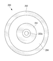
- FIG. 3 is a diagram of the nozzle portion of the first embodiment viewed along the central axis.
- the nozzle unit 200 has a double tube structure of the cylindrical powder nozzle 201 and the shield nozzle 202 arranged around the central axis A.
- a powder gas passage 203 On the inner peripheral side of the powder nozzle 201 is a powder gas passage 203 having a circular cross-sectional view.
- the powder gas flow path 203 communicates with a powder gas supply source (not shown), and distributes the powder gas supplied from the powder gas supply source along the arrow direction in FIG.
- the end of the powder gas passage 203 is a powder gas outlet 203a that opens to the outside.
- the powder gas flowing out from the powder gas outlet 203a is supplied to the laser beam irradiation position P.
- a tapered portion 201c is provided on the inner peripheral surface in the vicinity of the tip portion 201a of the powder nozzle 201 that forms the powder gas outlet 203a.
- the taper part 201c has a shape in which the inner diameter increases with a constant gradient toward the tip part 201a of the powder nozzle 201.
- the gradient of the taper portion 201c defines a range (spraying application range) in which the powder gas flowing out from the powder nozzle 201 diffuses from the central axis A.
- a space partitioned by the outer peripheral surface of the powder nozzle 201 and the inner peripheral surface of the shield nozzle 202 and having a circular cross section in the direction orthogonal to the central axis A is a shield gas flow path 204.
- the shield gas flow path 204 communicates with a shield gas supply source (not shown), and distributes the shield gas supplied from the shield gas supply source along the arrow direction in FIG.
- the end of the shield gas flow path 204 is a shield gas outlet 204a that opens to the outside.
- the shield gas that has flowed out of the shield gas outlet 204a is supplied to an annular region around the laser beam irradiation position P so as to isolate the laser beam irradiation position P.
- an outer peripheral surface 201b having a shape in which the outer diameter gradually decreases toward the tip portion 201a of the powder nozzle 201 is provided.
- the outer peripheral surface 201 b has an arc shape in cross section passing through the central axis A of the powder nozzle 201.
- the shield gas is a gas for isolating the laser beam irradiation position P (welded part) from the atmosphere containing oxygen. It is desirable that the powder gas and the shield gas flow in separate layers so as not to mix each other.
- the flow rate of the powder gas and the flow rate of the shield gas are adjusted so as to be substantially the same speed.
- the adjustment of the flow velocity is performed by appropriately setting various parameters such as the flow rate of the powder gas, the flow channel width of the powder gas flow channel 203, the flow rate of the shield gas, and the flow channel width of the shield gas flow channel 204.
- FIG. 6 is a cross-sectional view of a cross section passing through the central axis A of the nozzle unit 500 of the comparative example.
- the nozzle unit 500 of the comparative example includes a powder nozzle 501 and a shield nozzle 502.
- the powder nozzle 501 is provided with a powder gas flow path 503, and a space partitioned by the inner peripheral surface of the shield nozzle 502 and the outer peripheral surface of the powder nozzle 501 is a shield gas flow path 504.
- the tip portion 201 a of the nozzle portion 200 is provided with an outer peripheral surface 201 b having an arc shape in cross section.
- the vicinity of the tip of the nozzle unit 500 is different in that an outer peripheral surface parallel to the central axis A is provided.
- the position of the tip portion of the shield nozzle 502 of the comparative example shown in FIG. 6 retreats along the flow direction of the shield gas, rather than the position of the tip portion of the shield nozzle 202 of the first embodiment shown in FIG. Is in position.
- FIG. 1 An arrow schematically showing a vortex structure generated in the shield gas flowing out from the shield gas flow path is shown at the tip of the nozzle portion 500 in FIG.
- This vortex structure includes both a horizontal vortex having a vortex axis perpendicular to the flow direction of the shield gas and a vertical vortex having a vortex axis parallel to the flow direction of the shield gas.
- an outer peripheral surface parallel to the central axis A is provided in the vicinity of the tip of the powder nozzle 501 of the comparative example. Therefore, the shield gas that has passed through the tip of the nozzle unit 500 diffuses rapidly in a direction orthogonal to the central axis A. For this reason, the flow of the shielding gas is disturbed, and a vortex structure 505 is generated in the shielding gas.
- the position of the tip of the shield nozzle 502 of the comparative example is a position retracted along the flow direction of the shield gas. Therefore, at the position passing through the tip of the shield nozzle 502, the outer peripheral surface of the powder nozzle 501 exists on the side close to the central axis A, while the shield nozzle 502 does not exist on the side far from the central axis A. . Therefore, the shield gas rapidly diffuses in the direction away from the central axis A after passing through the tip of the shield nozzle 502. For this reason, the flow of the shielding gas is disturbed, and a vortex structure 505 is generated in the shielding gas.
- a large number of vortex structures 505 generated move along the flow direction of the shield gas and overlap with other vortex structures 505.
- Such a large vortex structure 506 acts to guide the atmosphere (oxygen) existing on the outer peripheral side of the vortex structure 506 with respect to the center axis A to the inside of the vortex structure 506 with respect to the center axis A. For this reason, oxygen flows into the laser beam irradiation position P where laser build-up welding is performed, and is guided to the welded portion to generate spatter, resulting in a reduction in welding quality.
- production of the vortex structure 505,506 is suppressed, the fall of the quality of welding is prevented.
- the welding method using the welding apparatus 100 of this embodiment is demonstrated.
- a powder gas containing a powder welding material is supplied to a joint portion between the main body portion 5 of the leading edge portion of the turbine blade and the protection portion 6 of the erosion resistant metal material using the welding apparatus 100,
- This is a method of executing a welding process in which build-up welding is performed on the main body portion 5 and the protection portion 6 of the erosion resistant metal material.
- generation of a large-scale vortex structure in the shield gas can be suppressed, and high-quality overlay welding using a laser can be performed.
- the welding apparatus 100 supplies the powder gas containing the powder welding material from the cylindrical powder nozzle 201 to the laser beam irradiation position P of the base material 400 that is the welding object. Then, overlay welding is performed.
- a shield gas is supplied to the laser beam irradiation position P from a cylindrical shield nozzle 202 arranged coaxially so as to cover the outer peripheral surface of the powder nozzle 201, and the laser beam irradiation position P is isolated.
- An outer peripheral surface 201b in the vicinity of the tip portion 201a of the powder nozzle has an arc shape whose outer diameter gradually decreases toward the tip portion 201a of the powder nozzle 201.
- the shield gas flowing out from the shield gas flow path 204 along the outer peripheral surface 201b of the powder nozzle 201 is orthogonal to the flow direction of the shield gas. It is difficult to generate a horizontal vortex with a vortex axis. In addition, the generation of the vertical vortex caused by the inclination of the vortex axis of the horizontal vortex in the jet of shield gas is also suppressed.
- the surrounding atmosphere oxygen
- the surrounding atmosphere oxygen
- FIG. 4 is a cross-sectional view in a cross section passing through the central axis A of the nozzle part 210 of the second embodiment.
- the second embodiment is a modification of the first embodiment, and is the same as the first embodiment, except for the case described below, and will not be described below.
- the nozzle portion 200 of the first embodiment is provided with a tapered portion 201c, whereas the nozzle portion 210 of the second embodiment is different in that a cross section is provided with an inner circumferential surface 201d.
- the inner peripheral surface 201d in the vicinity of the tip part 201a of the powder nozzle 201 has a shape in which the inner diameter gradually increases toward the tip part 201a of the powder nozzle 201. Further, as shown in FIG. 4, the inner peripheral surface 201 d has an arc shape in a cross section passing through the central axis A of the powder nozzle 201.
- the powder gas flowing out from the powder nozzle 201 along the inner peripheral surface 201d of the powder nozzle 201 is difficult to generate a horizontal vortex having a vortex axis perpendicular to the flow direction of the powder gas.
- generation of vertical vortices due to tilting of the vortex axis of the horizontal vortex in the powder gas jet is also suppressed. This prevents a problem that a vortex structure is generated in the powder gas and a vortex structure is generated in the shield gas due to the vortex structure.
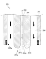
- FIG. 5 is a cross-sectional view taken along a central axis A of the nozzle unit 220 of the third embodiment.
- the third embodiment is a modification of the first embodiment, and is the same as the first embodiment except for the case specifically described below, and the description below is omitted.
- the nozzle portion 200 of the first embodiment has a flat inner peripheral surface at the tip portion of the shield nozzle 202, whereas the nozzle portion 220 of the third embodiment has a vortex suppressing member on the inner peripheral surface of the tip portion of the shield nozzle 202.
- the difference is that 202a is provided.
- the vortex suppressing member 202a is preferably provided at the tip of the shield nozzle 202, but may be provided at another position as long as it is near the tip.
- the nozzle unit 220 of the welding apparatus of the third embodiment is provided with a vortex suppressing member 202a on the inner peripheral surface in the vicinity of the tip of the shield nozzle 202.
- the vortex suppressing member 202 a is configured to include a plurality of protrusions that protrude toward the central axis A of the shield nozzle 202. This protrusion may be a rod-shaped member or an annular member extending in the circumferential direction of the central axis A.
- the vortex suppressing member 202a Since the vortex suppressing member 202a is provided on the inner peripheral surface in the vicinity of the tip of the shield nozzle 202, the vortex generated in the shield gas passing near the vortex suppressing member 202a is crushed by the vortex suppressing member 202a. As a result, even if a vortex is generated in the shield gas passing through the shield gas flow path 204 due to the influence of the shear stress generated between the shield gas flow path 204 and the wall surface of the shield gas flow path 204, the vortex is prevented from further growing. Is done. Therefore, generation of a large-scale vortex structure in the shield gas can be suppressed, and high-quality overlay welding using a laser can be performed.
Landscapes
- Engineering & Computer Science (AREA)
- Physics & Mathematics (AREA)
- Optics & Photonics (AREA)
- Mechanical Engineering (AREA)
- Plasma & Fusion (AREA)
- General Engineering & Computer Science (AREA)
- Chemical & Material Sciences (AREA)
- Materials Engineering (AREA)
- Toxicology (AREA)
- Electromagnetism (AREA)
- General Health & Medical Sciences (AREA)
- Health & Medical Sciences (AREA)
- Laser Beam Processing (AREA)
Abstract
Description
ここでいう渦構造には、シールドガスの流れ方向に直交する渦軸を持つ横渦と、シールドガスの流れ方向に平行な渦軸を持つ縦渦の両方が含まれる。横渦はシールドガスとシールドガスが流通するシールドノズルの壁面との摩擦や剥離が原因で発生し、縦渦はシールドガスの噴流が原因で発生する。
本発明の第1態様に係る溶接装置は、溶接対象物のレーザ光照射位置に対して、粉体の溶接材料を含むパウダーガスを供給する筒状のパウダーノズルと、前記パウダーノズルの外周面を覆うように同軸に配置され、前記レーザ光照射位置を隔離するためのシールドガスを供給する筒状のシールドノズルとを備え、前記パウダーノズルの先端部近傍の外周面は、前記パウダーノズルの前記先端部に向けて漸次外径が小さくなる形状であり、前記パウダーノズルの中心軸を通る断面での断面形状が円弧形状となっている。
従って、シールドガスに大規模な渦構造が発生することを抑制し、レーザを用いた高品質の肉盛溶接を行うことができる。
従って、シールドガスに大規模な渦構造が発生することを抑制し、レーザを用いた高品質の肉盛溶接を行うことができる。
このようにすることで、シールドガスに大規模な渦構造が発生することを抑制し、レーザを用いた高品質の肉盛溶接を行う溶接方法を提供することができる。
このようにすることで、シールドガスに大規模な渦構造が発生することを抑制し、レーザを用いた高品質の肉盛溶接が行われたタービン翼を提供することができる。
以下、本発明の第1実施形態の溶接装置100について、図1を参照しながら説明する。
図1は本実施形態の溶接装置100を示す概略構成図である。
溶接装置100は、レーザ光301が照射されるレーザ光照射位置Pに粉体の溶接材料を含むパウダーガスを供給することにより、レーザ光照射位置Pにおいて肉盛溶接を行う。
この溶接方法は、溶接装置100を用いてタービン翼前縁部分の本体部分5と耐エロ-ジョン性金属材料の保護部6との接合部に粉体の溶接材料を含むパウダーガスを供給し、本体部分5と耐エロ-ジョン性金属材料の保護部6とを肉盛溶接する溶接工程を実行するという方法である。
このような溶接方法によれば、シールドガスに大規模な渦構造が発生することを抑制し、レーザを用いた高品質の肉盛溶接を行うことができる。
従って、シールドガスに大規模な渦構造が発生することを抑制し、レーザを用いた高品質の肉盛溶接を行うことができる。
以下、本発明の第2実施形態の溶接装置について、図4を参照しながら説明する。
図4は、第2実施形態のノズル部210の中心軸Aを通る断面での断面図である。
以下、本発明の第3実施形態の溶接装置について、図5を参照しながら説明する。
図5は、第3実施形態のノズル部220の中心軸Aを通る断面での断面図である。
なお、渦抑制部材202aは、シールドノズル202の先端部に設けられるのが望ましいが、先端部近傍であれば他の位置に設けるようにしても良い。
従って、シールドガスに大規模な渦構造が発生することを抑制し、レーザを用いた高品質の肉盛溶接を行うことができる。
200,210,220 ノズル部
201 パウダーノズル
201a 先端部
201b 外周面
201c テーパ部
201d 内周面
202 シールドノズル
202a 渦抑制部材
203 パウダーガス流路
203a パウダーガス流出口
204 シールドガス流路
204a シールドガス流出口
300 レーザ部
301 レーザ光
400 母材(溶接対象物)
A 中心軸
B レーザ光軸
P レーザ光照射位置
Claims (6)
- 溶接対象物のレーザ光照射位置に対して、粉体の溶接材料を含むパウダーガスを供給する筒状のパウダーノズルと、
前記パウダーノズルの外周面を覆うように同軸に配置され、前記レーザ光照射位置を隔離するためのシールドガスを供給する筒状のシールドノズルとを備え、
前記パウダーノズルの先端部近傍の外周面は、前記パウダーノズルの前記先端部に向けて漸次外径が小さくなる形状であり、前記パウダーノズルの中心軸を通る断面での断面形状が円弧形状となっている溶接装置。 - 前記パウダーノズルの先端部近傍の内周面が、前記パウダーノズルの前記先端部に向けて漸次内径が大きくなる形状であり、前記パウダーノズルの中心軸を通る断面での断面形状が円弧形状となっている請求項1に記載の溶接装置。
- 溶接対象物のレーザ光照射位置に対して、粉体の溶接材料を含むパウダーガスを供給する筒状のパウダーノズルと、
前記パウダーノズルの外周面を覆うように同軸に配置され、前記レーザ光照射位置を隔離するためのシールドガスを供給する筒状のシールドノズルとを備え、
前記シールドノズルの先端部近傍の内周面に、前記シールドガスによる渦の発生を抑制する渦抑制部材が設けられている溶接装置。 - 前記渦抑制部材が、前記シールドノズルの中心軸に向けて突出する複数の突起部を備える請求項3に記載の溶接装置。
- 請求項1から請求項4のいずれか1項に記載の溶接装置を用いてタービン翼前縁部分の本体部と耐エロ-ジョン性金属材料との接合部に粉体の溶接材料を含むパウダーガスを供給し、前記本体部と前記耐エロ-ジョン性金属材料とを肉盛溶接する溶接工程を備えた溶接方法。
- 請求項5に記載の溶接方法により耐エロ-ジョン性金属材料が肉盛溶接されたタービン翼。
Priority Applications (5)
| Application Number | Priority Date | Filing Date | Title |
|---|---|---|---|
| US15/551,532 US20180036837A1 (en) | 2015-02-19 | 2015-02-19 | Welding device, welding method, and turbine blade |
| CN201580076417.9A CN107249811A (zh) | 2015-02-19 | 2015-02-19 | 焊接装置、焊接方法、及涡轮叶片 |
| KR1020177021744A KR20170097213A (ko) | 2015-02-19 | 2015-02-19 | 용접 장치, 용접 방법 및 터빈 날개 |
| PCT/JP2015/054585 WO2016132502A1 (ja) | 2015-02-19 | 2015-02-19 | 溶接装置、溶接方法、及びタービン翼 |
| DE112015006194.0T DE112015006194T5 (de) | 2015-02-19 | 2015-02-19 | Schweißvorrichtung, Schweißverfahren und Turbinenschaufel |
Applications Claiming Priority (1)
| Application Number | Priority Date | Filing Date | Title |
|---|---|---|---|
| PCT/JP2015/054585 WO2016132502A1 (ja) | 2015-02-19 | 2015-02-19 | 溶接装置、溶接方法、及びタービン翼 |
Publications (1)
| Publication Number | Publication Date |
|---|---|
| WO2016132502A1 true WO2016132502A1 (ja) | 2016-08-25 |
Family
ID=56692613
Family Applications (1)
| Application Number | Title | Priority Date | Filing Date |
|---|---|---|---|
| PCT/JP2015/054585 Ceased WO2016132502A1 (ja) | 2015-02-19 | 2015-02-19 | 溶接装置、溶接方法、及びタービン翼 |
Country Status (5)
| Country | Link |
|---|---|
| US (1) | US20180036837A1 (ja) |
| KR (1) | KR20170097213A (ja) |
| CN (1) | CN107249811A (ja) |
| DE (1) | DE112015006194T5 (ja) |
| WO (1) | WO2016132502A1 (ja) |
Cited By (1)
| Publication number | Priority date | Publication date | Assignee | Title |
|---|---|---|---|---|
| WO2018176101A1 (en) | 2017-03-29 | 2018-10-04 | Laserbond Limited | Methods, systems and assemblies for laser deposition |
Families Citing this family (1)
| Publication number | Priority date | Publication date | Assignee | Title |
|---|---|---|---|---|
| CN117564518B (zh) * | 2024-01-15 | 2024-05-17 | 洛阳船舶材料研究所(中国船舶集团有限公司第七二五研究所) | 一种真空激光焊接装置及焊接方法 |
Citations (4)
| Publication number | Priority date | Publication date | Assignee | Title |
|---|---|---|---|---|
| US5477025A (en) * | 1994-01-14 | 1995-12-19 | Quantum Laser Corporation | Laser nozzle |
| GB2476836A (en) * | 2010-01-12 | 2011-07-13 | Rolls Royce Plc | Laser Deposition Spray Nozzle |
| US20110253687A1 (en) * | 2008-12-23 | 2011-10-20 | Commissariat A L'energie Atomique Et Aux Energies Alternatives | Mouth of a hood for sucking up fine particles, and laser device for ablating a surface layer of a wall comprising such a hood |
| WO2013046950A1 (ja) * | 2011-09-30 | 2013-04-04 | 株式会社日立製作所 | パウダ供給ノズルおよび肉盛溶接方法 |
Family Cites Families (11)
| Publication number | Priority date | Publication date | Assignee | Title |
|---|---|---|---|---|
| JPS62167866A (ja) * | 1986-01-17 | 1987-07-24 | Toshiba Corp | タ−ビン翼 |
| JPS62207585A (ja) * | 1986-03-05 | 1987-09-11 | Suzuki Motor Co Ltd | ア−ク溶接用チツプ |
| US5453329A (en) * | 1992-06-08 | 1995-09-26 | Quantum Laser Corporation | Method for laser cladding thermally insulated abrasive particles to a substrate, and clad substrate formed thereby |
| CN1274451C (zh) * | 2004-07-09 | 2006-09-13 | 北京工业大学 | 一种通过粉末强化吸收的铝合金激光焊接方法 |
| GB0504576D0 (en) * | 2005-03-05 | 2005-04-13 | Alstom Technology Ltd | Turbine blades and methods for depositing an erosion resistant coating on the same |
| US7358457B2 (en) * | 2006-02-22 | 2008-04-15 | General Electric Company | Nozzle for laser net shape manufacturing |
| CN101138755A (zh) * | 2006-09-08 | 2008-03-12 | 陈国雄 | 分体式激光熔覆同轴送粉喷嘴 |
| BRPI0820834B1 (pt) * | 2007-12-11 | 2018-01-02 | Tetron, Inc. | Inibidor de vórtice |
| JP3158626U (ja) * | 2010-01-29 | 2010-04-08 | 新光機器株式会社 | ガスシールドアーク溶接用シールドノズル |
| WO2013157036A1 (ja) * | 2012-04-18 | 2013-10-24 | Murata Akihisa | 狭窄ノズル及びこれを用いたtig溶接用トーチ |
| CN102745328A (zh) * | 2012-07-13 | 2012-10-24 | 北京理工大学 | 具有桨尖涡流抑制效应的涵道 |
-
2015
- 2015-02-19 CN CN201580076417.9A patent/CN107249811A/zh active Pending
- 2015-02-19 US US15/551,532 patent/US20180036837A1/en not_active Abandoned
- 2015-02-19 WO PCT/JP2015/054585 patent/WO2016132502A1/ja not_active Ceased
- 2015-02-19 KR KR1020177021744A patent/KR20170097213A/ko not_active Ceased
- 2015-02-19 DE DE112015006194.0T patent/DE112015006194T5/de not_active Ceased
Patent Citations (4)
| Publication number | Priority date | Publication date | Assignee | Title |
|---|---|---|---|---|
| US5477025A (en) * | 1994-01-14 | 1995-12-19 | Quantum Laser Corporation | Laser nozzle |
| US20110253687A1 (en) * | 2008-12-23 | 2011-10-20 | Commissariat A L'energie Atomique Et Aux Energies Alternatives | Mouth of a hood for sucking up fine particles, and laser device for ablating a surface layer of a wall comprising such a hood |
| GB2476836A (en) * | 2010-01-12 | 2011-07-13 | Rolls Royce Plc | Laser Deposition Spray Nozzle |
| WO2013046950A1 (ja) * | 2011-09-30 | 2013-04-04 | 株式会社日立製作所 | パウダ供給ノズルおよび肉盛溶接方法 |
Cited By (3)
| Publication number | Priority date | Publication date | Assignee | Title |
|---|---|---|---|---|
| WO2018176101A1 (en) | 2017-03-29 | 2018-10-04 | Laserbond Limited | Methods, systems and assemblies for laser deposition |
| EP3600754A4 (en) * | 2017-03-29 | 2021-01-06 | Laserbond Limited | METHODS, SYSTEMS AND ARRANGEMENTS FOR LASER DEPOSITION |
| US12128499B2 (en) | 2017-03-29 | 2024-10-29 | Laserbond Limited | Methods, systems and assemblies for laser deposition |
Also Published As
| Publication number | Publication date |
|---|---|
| KR20170097213A (ko) | 2017-08-25 |
| DE112015006194T5 (de) | 2017-10-26 |
| US20180036837A1 (en) | 2018-02-08 |
| CN107249811A (zh) | 2017-10-13 |
Similar Documents
| Publication | Publication Date | Title |
|---|---|---|
| US9315903B2 (en) | Laser microcladding using powdered flux and metal | |
| RU2573454C2 (ru) | Способ соединительной сварки оснащенных покрытием стальных листов | |
| CN101291773B (zh) | 具有金属蒸气毛细管形成控制的激光束焊接方法 | |
| JP5485279B2 (ja) | ダイナミックジェットノズルを用いるco2レーザー溶接方法 | |
| US20130140279A1 (en) | Laser re-melt repair of superalloys using flux | |
| US20130136868A1 (en) | Selective laser melting / sintering using powdered flux | |
| WO2013046950A1 (ja) | パウダ供給ノズルおよび肉盛溶接方法 | |
| US20130140280A1 (en) | Arc welding device and process using a mig/mag torch combined with a tig torch | |
| JP2009530112A (ja) | 溶接のための装置及び方法 | |
| US20120223057A1 (en) | Gas tungsten arc welding using flux coated electrodes | |
| CN101909807B (zh) | 使用能稳定孔隙的喷嘴的激光焊接方法 | |
| KR20150110815A (ko) | 분말형 용제와 금속을 포함하는 코어 공급 재료를 사용한 합금 클래딩 | |
| JP2009107017A (ja) | 溶接部の品質を制御する方法 | |
| JP2016120506A (ja) | レーザ溶接方法 | |
| JP6109698B2 (ja) | 溶接装置及び溶接方法 | |
| JP6512880B2 (ja) | シールドノズルおよびシールド方法 | |
| CN104955983A (zh) | 使用粉末焊剂和金属的激光微细熔覆 | |
| JP2012192436A (ja) | レーザクラッディング方法 | |
| JP2010234373A (ja) | レーザ加工用ノズル及びレーザ加工装置 | |
| JP2623993B2 (ja) | レーザ加工ヘッド | |
| JP2018009551A (ja) | 蒸気タービン翼の製造方法 | |
| CN101426609A (zh) | 用于焊接的装置和方法 | |
| US20180036837A1 (en) | Welding device, welding method, and turbine blade | |
| DE102004018280B4 (de) | Verfahren sowie Düse zur Bearbeitung oder Analyse eines Werkstücks oder einer Probe mit einem energetischen Strahl | |
| JP2020049505A (ja) | 溶接装置及びノズル装置 |
Legal Events
| Date | Code | Title | Description |
|---|---|---|---|
| 121 | Ep: the epo has been informed by wipo that ep was designated in this application |
Ref document number: 15882605 Country of ref document: EP Kind code of ref document: A1 |
|
| ENP | Entry into the national phase |
Ref document number: 20177021744 Country of ref document: KR Kind code of ref document: A |
|
| WWE | Wipo information: entry into national phase |
Ref document number: 15551532 Country of ref document: US |
|
| WWE | Wipo information: entry into national phase |
Ref document number: 112015006194 Country of ref document: DE |
|
| NENP | Non-entry into the national phase |
Ref country code: JP |
|
| 122 | Ep: pct application non-entry in european phase |
Ref document number: 15882605 Country of ref document: EP Kind code of ref document: A1 |