WO2016132468A1 - データ評価方法および装置、故障診断方法および装置 - Google Patents
データ評価方法および装置、故障診断方法および装置 Download PDFInfo
- Publication number
- WO2016132468A1 WO2016132468A1 PCT/JP2015/054369 JP2015054369W WO2016132468A1 WO 2016132468 A1 WO2016132468 A1 WO 2016132468A1 JP 2015054369 W JP2015054369 W JP 2015054369W WO 2016132468 A1 WO2016132468 A1 WO 2016132468A1
- Authority
- WO
- WIPO (PCT)
- Prior art keywords
- data
- input
- output
- neural network
- distance
- Prior art date
Links
Images


Classifications
-
- G—PHYSICS
- G06—COMPUTING; CALCULATING OR COUNTING
- G06N—COMPUTING ARRANGEMENTS BASED ON SPECIFIC COMPUTATIONAL MODELS
- G06N3/00—Computing arrangements based on biological models
- G06N3/02—Neural networks
- G06N3/04—Architecture, e.g. interconnection topology
-
- G—PHYSICS
- G08—SIGNALLING
- G08B—SIGNALLING OR CALLING SYSTEMS; ORDER TELEGRAPHS; ALARM SYSTEMS
- G08B31/00—Predictive alarm systems characterised by extrapolation or other computation using updated historic data
Definitions
- the present invention relates to a technique for evaluating data used by a neural network, and a technique for diagnosing equipment failure using the data.
- the neural network is a model that simulates the function of brain neurons.
- the neural network includes an input node and an output node, and when a value is input to the input node, a value corresponding to the output node input is output.
- the output value of the output node is calculated as a value obtained by converting the weighted sum of the input values for the input node by the output function f.
- a multi-layer neural network can also be constructed by connecting pairs of input nodes and output nodes in a multistage manner and using the output from the output node as an input to the input node in the next stage.
- a back-propagation algorithm is known as an algorithm that uses a pair of an input and an output to be obtained from the input as learning data and learns the weight of each node so that an input / output relationship that matches the learning data is obtained.
- One of the merits of neural networks is that it is possible to construct a system that can obtain the desired output without analyzing what kind of feature value is extracted from the input data to obtain the desired output.
- Deep neural networks have been applied to many fields such as image recognition, speech recognition, handwritten character recognition, etc., and high performance has been obtained.
- Patent Document 1 describes a technique for diagnosing a device failure using a neural network.
- the method of diagnosing a device failure using a neural network is roughly divided into the following two types: (a) Normal data using a neural network (restoration type neural network) configured to output input data as it is. (B) A neural network (discriminating neural network) that learns an input / output pair, and a signal output from the device and its signal The corresponding device status is learned to determine whether the input data is normal or abnormal.
- a typical example of a restoration type neural network is called an auto encoder.
- the fault diagnosis method using a restoration type neural network can be learned only with normal data, but there is a problem that it is difficult to identify an abnormality near the boundary when the space occupied by normal data and the space occupied by abnormal data are close to each other.
- the fault diagnosis method using the discrimination type neural network can accurately distinguish between normal data and abnormal data, but there is a problem that the determination result is undefined for unlearned data.
- the present invention has been made in view of the above-described problems, and an object of the present invention is to provide a technique capable of mutually complementing the characteristics of the restoration-type neural network and the identification-type neural network.
- the present invention determines whether the input data is within a previously learned range by restoring the input data using the restoration type neural network, and evaluates the judgment result by the discrimination type neural network using the result. To do.
- the present invention it is possible to determine whether or not the input data is within the learning range of the discriminating neural network. Thereby, the influence at the time of discriminating judgment type
- mold neural network can be suppressed.
- FIG. 3 is a graph showing a result of fault diagnosis performed using the block diagrams shown in FIGS. 1 and 2.
- FIG. It is a graph which shows the example which discriminate
- FIG. 2 is a functional block diagram of a failure diagnosis apparatus 700 according to Embodiment 1.
- FIG. It is a figure which shows the process which comprises the identification type
- FIG. It is the figure which showed typically how the feature-value space of input data 710 is distinguished by the comparator 760.
- FIG. It is the figure which showed typically how the feature-value space of the input data 710 is divided by the diagnostic result output device 730.
- FIG. 5 is a flowchart for explaining the operation of the failure diagnosis apparatus 700. It is a graph which shows the calculation result by the distance calculator 740.
- FIG. 1 is a block diagram for explaining a method of diagnosing equipment failure using an auto encoder.
- the auto encoder 120 performs learning in advance so that a signal output when a device to be diagnosed operates normally is used as learning data, and the input data is restored and output as it is. Since the auto encoder 120 learns using only normal data, when data other than normal data is input, it is expected that the output data does not match the input data.
- the signal sequence output by the device to be diagnosed is input as input data 110 to the auto encoder 120, and the restoration data 130 is acquired.
- the distance calculator 140 obtains the distance between the input data 110 and the restored data 130.
- the comparator 160 compares the distance with the reference value 150, and when the distance is greater than the reference value 150, the comparator 160 outputs a determination result 170 indicating that the input data 110 is abnormal (that is, the device has failed), When the distance is less than or equal to the reference value 150, a determination result 170 indicating that the input data 110 is normal (that is, the device is normal) is output.
- the boundary for determining whether or not the input data 110 is normal varies depending on the reference value 150.
- the reference value 150 may be a case where it is difficult to provide the reference value 150 that can satisfactorily identify all signal string patterns of the input data 110.
- FIG. 2 is a block diagram for explaining a method of diagnosing a device failure using a discrimination type neural network.
- the discriminating neural network 220 learns in advance a pair of a signal output during normal operation of the device to be diagnosed and a determination result indicating that the device is operating normally, and the device to be diagnosed is abnormal. A pair of a signal output during operation and a determination result indicating that the device is operating abnormally at that time is learned in advance.
- the discrimination type neural network 220 generally includes an intermediate layer 221 that has been learned as an auto encoder, and an identification layer 222 that associates the output of the intermediate layer 221 with a determination result.
- a signal sequence output from the diagnosis target device is input as input data 210 to the discriminating neural network 220, and the discriminating neural network 220 generates an output value according to the learning result.
- the diagnosis result output unit 230 outputs the determination result 240 by shaping the output value as necessary.
- the discriminating neural network 220 when input data 210 that has not been learned in advance by the discriminating neural network 220 is input, the discriminating neural network 220 appropriately determines whether or not the input data 210 is normal. Therefore, the accuracy of the determination result 240 is not necessarily good.
- FIG. 3 is a graph showing the results of failure diagnosis using the block diagrams shown in FIGS.
- the upper part shows the result when the auto encoder of FIG. 1 is used, and the lower part shows the result when the identification type neural network of FIG. 2 is used.
- a section 310 corresponds to normal data, and a section 330 corresponds to abnormal data.
- the portion 321 included in the section 320 should be determined as abnormal data originally, but is erroneously determined as normal. By reducing the reference value 150 (shifting downward in the vertical axis direction), the portion 321 can be determined to be abnormal. However, if so, there is a possibility that data determined to be normal in FIG. 3 exceeds the reference value 150 and erroneously determined to be abnormal. In the case shown in the upper part of FIG. 3, it is difficult to set an appropriate reference value 150 for all input data 110.
- the discriminating neural network needs to learn using both normal data and abnormal data, but has an advantage of high discrimination performance in the vicinity of the boundary between the two.
- FIG. 4 is a graph showing an example in which the discriminating neural network makes a misjudgment.
- the determination is made correctly.
- the section 430 in which noise that is not included in either normal data or abnormal data is input there is a portion 431 that is originally determined to be abnormal but is erroneously determined to be normal. . This is because there is no restriction on the determination result for an unlearned data area, and the determination result is undefined.
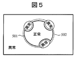
- FIG. 5 is a conceptual diagram showing the relationship between the input feature space and the diagnosis result when the fault diagnosis is performed using the auto encoder.
- the inside of the boundary 501 is normal data
- the outside of the boundary 502 is abnormal data.
- erroneous determination is likely to occur particularly in a portion where normal data and abnormal data are in contact (for example, a region between the boundaries 501 and 502). For this reason, it is difficult to accurately identify a complex boundary using only a simple one-dimensional reference value 150.
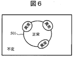
- FIG. 6 is a conceptual diagram showing the relationship between the input feature amount space and the diagnosis result when the fault diagnosis is performed using the discriminating neural network.
- the boundary between normal data and abnormal data is clear, but it is uncertain whether the determination result is normal or abnormal for an area where no learning data is given.
- ⁇ Embodiment 1> In the first embodiment of the present invention, a method for detecting a sign of an abnormality or abnormality of the device by using a signal from a sensor attached to a target device that performs abnormality detection or predictive diagnosis as an input to the neural network will be described. To do.
- FIG. 7 is a functional block diagram of the failure diagnosis apparatus 700 according to the first embodiment.
- the failure diagnosis apparatus 700 includes an identification type neural network 720 and a diagnosis result output unit 730, similarly to the configuration described in FIG. These functions are the same as those of the discrimination type neural network 220 and the diagnosis result output unit 230 described in FIG. That is, the discrimination type neural network 720 learns in advance a pair of input data 710 output from the target device and a diagnosis result corresponding to the input data 710, and the diagnosis result output unit 730 outputs the diagnosis result.
- an auto encoder that restores the input data 710 is configured.
- An identification type neural network 720 is formed by connecting an intermediate layer 721 that is a front part of the auto encoder and an identification layer 723 that outputs a diagnosis result based on the output of the intermediate layer 721. The process of forming the discrimination type neural network 720 will be described again.
- the second intermediate layer 781 with the weights between the layers reversed is temporarily connected to the output side of the intermediate layer 721 so that the input data 710 can be restored.
- the second intermediate layer 781 is removed from the discrimination type neural network 720.
- the restoration type neural network 780 is configured using the second intermediate layer 781.
- the restoration type neural network 780 is a neural network that has been learned in advance as an auto encoder, receives the output of the hidden layer 722 that is the output stage of the intermediate layer 721 at the input layer 782, and reverses the interlayer connection of the intermediate layer 721 in the opposite direction. By following this, restored data 790 obtained by restoring the input data 710 is output.
- the restoration type neural network 780 does not necessarily need to use the second intermediate layer 781 itself, as long as the signal output from the hidden layer 722 can be received by the input layer 782 and reproduced. However, since the second intermediate layer 781 can be configured only by inverting the weight W ij of the intermediate layer 721 to make W T ij , it is convenient to use this.
- the distance calculator 740 calculates a distance (for example, Euclidean distance) between the restoration data 790 and the input data 710.
- the comparator 760 determines whether or not the distance calculated by the distance calculator 740 is within the reference value 750 and outputs the result.
- the input data 710 is included in the range learned in advance in the process of configuring the discriminative neural network 720 (that is, when the input data 710 is in or near the range of the feature amount space learned in advance) It is assumed that the distance between the data 710 and the restored data 790 is small. On the other hand, when the input data 710 is not included in the previously learned range, the distance is assumed to be large.
- the comparator 760 can determine whether or not the input data 710 is included in a range learned in advance in the process of configuring the discrimination type neural network 720.
- the diagnosis result output unit 770 outputs the diagnosis result for the target device using the output of the diagnosis result output unit 730 and the output of the comparator 760. If the distance calculated by the distance calculator 740 is within the reference value 750 (that is, the input data 710 is within a previously learned range), the output of the diagnostic result output unit 730 is output as it is. If the distance calculated by the distance calculator 740 is greater than the reference value 750 (that is, the input data 710 is out of the pre-learned range), at least data indicating that the input data 710 is out of the pre-learned range is output. To do.
- FIG. 8 is a diagram illustrating a process of configuring the discrimination type neural network 720.
- a method for learning the discrimination type neural network 720 for example, Grayy Layer-Wise Training can be used. From the input layer 801 to the intermediate layer 802, learning is performed as an auto encoder for each layer. At that time, in each layer, learning is performed so that the value of the input node can be restored from the value of the output node calculated for the input node of the layer, and the output of the previous layer is used as the input of the next layer. Therefore, the configuration is such that the value of the input layer 801 is always returned when the layer is traced backward.
- a decoder that restores the input value of the input layer 801 from the output value of the intermediate layer 802 can be configured by inverting the weights from the input layer 801 to the intermediate layer 802. This decoder can be used as the restoration type neural network 780.
- the weight between the intermediate layer 802 and the output layer 803 can be learned by, for example, back propagation. Thereafter, the weight of the discrimination type neural network 720 as a whole is finely adjusted (fine tuning).
- FIG. 9 is a diagram schematically showing how the feature amount space of the input data 710 is distinguished by the comparator 760. Assuming that the space occupied by abnormal data and normal data in FIGS. 5 to 6 is within the range 901 of the learning data, the comparator 760 determines whether or not the input data 710 is within this range 901.
- FIG. 10 is a diagram schematically showing how the feature amount space of the input data 710 is divided by the diagnosis result output unit 730.
- Abnormal data and normal data learned in advance by the discriminating neural network 720 are accurately identified, and the determination result is undefined for regions outside the range of the learning data.
- the discrimination type neural network 720 outputs a normal / abnormal discrimination result even in this indefinite region, but the discrimination result is not reliable. Therefore, in the first embodiment, the diagnosis result output unit 770 uses both the output of the diagnosis result output unit 730 and the output of the comparator 760 so that such an unreliable discrimination result is not output.
- FIG. 11 is a flowchart for explaining the operation of the failure diagnosis apparatus 700. Hereinafter, each step of FIG. 11 will be described.
- the identification type neural network 720 receives the input data 710 (S1101). The identification type neural network 720 determines whether the input data 710 is normal or abnormal based on the previously learned result (S1102).
- the restoration type neural network 780 receives the output of the hidden layer 722 of the identification type neural network 720 as an input in the input layer 782 and generates restoration data 790 (S1103).
- the distance calculator 740 obtains the distance between the input data 710 and the restored data 790 (S1104).
- Steps S1105 to S1107 The comparator 760 determines whether or not the distance calculated in step S1104 is greater than the reference value 750 (S1105). When the distance is less than or equal to the reference value 750, the diagnosis result output unit 770 outputs the determination result by the discrimination type neural network 720 as it is (S1106). When the distance is greater than the reference value 750, the diagnostic result output unit 770 outputs a determination result indicating that at least the input data 710 is out of the learning range (S1107).
- FIG. 12 is a graph showing a calculation result by the distance calculator 740. Here, the calculation result for the same input data as in FIG. 4 is shown. In a section 1210 in which normal data is input and a section 1220 in which abnormal data is input, the distance between the input data 710 and the restored data 790 is small. On the other hand, in a section 1230 where noise that has not been learned in advance is input, the distance between the input data 710 and the restored data 790 is large. By setting the reference value 750 in the vicinity of the center of the vertical axis in FIG. 12, such noise can be detected when input.
- the failure diagnosis apparatus 700 generates the restoration data 790 by inputting the output of the intermediate layer 721 included in the discrimination type neural network 720 to the restoration type neural network 780, and inputs it. By comparing the data 710 and the restored data 790, it is determined whether or not the input data 710 is within the learning range. As a result, the input data 710 that cannot be accurately determined by the discriminating neural network 720 can be excluded, so that the determination accuracy can be improved.
- the restoration type neural network 780 can be formed by inverting the weight of the auto encoder created in the course of learning the discriminating type neural network 720. Thereby, the process of learning the identification type neural network 720 can be efficiently reused to improve the determination accuracy.
- the discrimination type neural network 720 determines whether the target device is normal or abnormal based on the input data 710. However, when the input data 710 suggests other states, It is also possible to learn and discriminate about states other than normal / abnormal. For example, when it is possible to determine a sign that the target device will fail based on the input data 710, a determination result to that effect can be learned in advance.
- the diagnosis result output unit 770 when the input data 710 is outside the learning range, the diagnosis result output unit 770 outputs at least a determination result to that effect.
- the diagnosis result output unit 770 may output the determination result by the comparator 760 together with the determination result by the discrimination type neural network 720.
- the determination result by the comparator 760 can be used as the reliability of the determination result by the discrimination type neural network 720.
- the diagnosis result output unit 770 may overwrite the determination result by the identification type neural network 720 and output the determination result that the target device is abnormal.
- the distance calculator 740 calculates the distance between the input data 710 and the restored data 790, but the method for calculating this distance can determine the similarity between the two data. Anything is acceptable. For example, Euclidean distance between data series, similarity, and the like can be used as the output of the distance calculator 740. Furthermore, the distance itself calculated by the distance calculator 740 can be output as the output of the diagnosis result output unit 770. In this case, the distance can be used as the reliability of the determination result by the identification type neural network 720.
- the output of the hidden layer 722 immediately before the identification layer 723 is input to the restoration type neural network 780, but the input to the restoration type neural network 780 is not limited to this.
- the restoration type neural network 780 also includes a plurality of layers obtained by inverting this. It is considered that the restoration data 790 can be generated by inputting the output at any stage of the hidden layer 722 to the corresponding layer of the restoration type neural network 780. For example, by inputting the output of the hidden layer 722 immediately before the identification layer 723 to the second layer of the restoration type neural network 780, the restoration type neural network 780 functions as an auto encoder. Similar results can be obtained.
- the present invention is not limited to the embodiments described above, and includes various modifications.
- the above embodiment has been described in detail for easy understanding of the present invention, and is not necessarily limited to the one having all the configurations described.
- a part of the configuration of one embodiment can be replaced with the configuration of another embodiment.
- the configuration of another embodiment can be added to the configuration of a certain embodiment. Further, with respect to a part of the configuration of each embodiment, another configuration can be added, deleted, or replaced.
- the failure diagnosis apparatus 700 described in the first and second embodiments, only a part for determining whether or not the input data 710 is within the learning range of the identification type neural network 720 is used. Whether it is suitable as an input to 720 can be evaluated. Specifically, the distance between the input data 710 and the restored data 790 can be acquired and the evaluation can be performed based on the distance.
- the above components, functions, processing units, processing means, etc. may be realized in hardware by designing some or all of them, for example, with an integrated circuit.
- Each of the above-described configurations, functions, and the like may be realized by software by interpreting and executing a program that realizes each function by the processor.
- Information such as programs, tables, and files for realizing each function can be stored in a recording device such as a memory, a hard disk, an SSD (Solid State Drive), or a recording medium such as an IC card, an SD card, or a DVD.
- 220 Discrimination type neural network
- 230 Diagnosis result output unit
- 710 Input data
- 720 Discrimination type neural network
- 730 Diagnosis result output unit
- 740 Distance calculator
- 750 Reference value
- 760 Comparator
- 770 Diagnosis result output unit
- 780 restoration type neural network
- 790 restoration data.
Landscapes
- Engineering & Computer Science (AREA)
- Physics & Mathematics (AREA)
- Theoretical Computer Science (AREA)
- General Physics & Mathematics (AREA)
- Computing Systems (AREA)
- General Health & Medical Sciences (AREA)
- Artificial Intelligence (AREA)
- Computational Linguistics (AREA)
- Data Mining & Analysis (AREA)
- Evolutionary Computation (AREA)
- Biomedical Technology (AREA)
- Molecular Biology (AREA)
- Biophysics (AREA)
- General Engineering & Computer Science (AREA)
- Life Sciences & Earth Sciences (AREA)
- Mathematical Physics (AREA)
- Software Systems (AREA)
- Health & Medical Sciences (AREA)
- Business, Economics & Management (AREA)
- Emergency Management (AREA)
- Testing And Monitoring For Control Systems (AREA)
Abstract
本発明は、復元型ニューラルネットワークと識別型ニューラルネットワークそれぞれの特徴を互いに補完することのできる技術を提供することを目的とする。本発明は、復元型ニューラルネットワーク(780)を用いて入力データを復元することにより、入力データがあらかじめ学習した範囲内であるか否かを判定し、その結果を用いて識別型ニューラルネットワーク(720)による判定結果を評価する。
Description
本発明は、ニューラルネットワークが使用するデータを評価する技術、およびこれを用いて機器の故障を診断する技術に関するものである。
ニューラルネットワークは、脳の神経細胞の働きを模擬したモデルである。ニューラルネットワークは、入力ノードと出力ノードを備え、入力ノードに対して値を入力すると、出力ノード入力に応じた値を出力する。出力ノードの出力値は、入力ノードに対する入力値の重み付け和を出力関数fにより変換した値として計算される。入力ノードと出力ノードのペアを多段的に連結し、出力ノードからの出力を次段の入力ノードに対する入力として用いることにより、多層ニューラルネットワークを構築することもできる。
入力とその入力から得られるべき出力のペアを学習データとして用い、学習データと合致する入出力関係が得られるように各ノードの重みを学習するアルゴリズムとして、バックプロパゲーションアルゴリズムが知られている。
ニューラルネットワークのメリットの1つとして、入力データからどういった特徴量を取り出せば望む出力が得られるのかを解析することなしに、望んだ出力が得られるシステムを構築することができる点がある。
ニューラルネットワークの層数が増えるにしたがって、より複雑な入出力関係を学習することができるが、学習時間が増大することが課題である。学習時間の問題を解決する手法として、Greedy Layer-Wise Training of Deep Architecturesが知られている。同手法により、深い階層のニューラルネットワークを実用的な時間で学習することができる。深い階層構造を持つニューラルネットワークは、ディープニューラルネットワークとよばれている。ディープニューラルネットワークは、画像認識、音声認識、手書き文字認識などの多くの分野に応用され、高い性能が得られている。
下記特許文献1は、ニューラルネットワークを用いて機器の故障を診断する技術について記載している。
ニューラルネットワークを用いて機器の故障を診断する方法は、大きく以下の2つに分けられる:(a)入力データをそのまま出力するように構成されたニューラルネットワーク(復元型ニューラルネットワーク)を用いて正常データのみを学習し、入力データが正常であるか否かを判定する、(b)入力と出力のペアを学習するニューラルネットワーク(識別型ニューラルネットワーク)を用いて、機器が出力する信号とその信号に対応する機器状態を学習し、入力データが正常/異常いずれであるかを判定する。復元型ニューラルネットワークの代表例として、オートエンコーダと呼ばれるものがある。
復元型ニューラルネットワークを用いる故障診断方法は、正常データのみで学習できるが、正常データが占める空間と異常データが占める空間が接近している場合、境界付近における異常識別が難しいという課題がある。他方で識別型ニューラルネットワークを用いる故障診断方法は、正常データと異常データを精度よく区別できるが、未学習のデータについては判定結果が不定となる課題がある。
本発明は、上記のような課題に鑑みてなされたものであり、復元型ニューラルネットワークと識別型ニューラルネットワークそれぞれの特徴を互いに補完することのできる技術を提供することを目的とする。
本発明は、復元型ニューラルネットワークを用いて入力データを復元することにより、入力データがあらかじめ学習した範囲内であるか否かを判定し、その結果を用いて識別型ニューラルネットワークによる判定結果を評価する。
本発明によれば、入力データが識別型ニューラルネットワークの学習範囲内であるか否かを判定することができる。これにより、識別型ニューラルネットワークが誤判定した場合の影響を抑制することができる。
<従来手法の課題について>
以下では本発明の理解を促進するため、まず従来の復元型ニューラルネットワーク(例えばオートエンコーダ)による故障診断手法の課題、および従来の識別型ニューラルネットワークによる故障診断手法の課題について詳述し、その後に本発明の実施形態について説明する。
以下では本発明の理解を促進するため、まず従来の復元型ニューラルネットワーク(例えばオートエンコーダ)による故障診断手法の課題、および従来の識別型ニューラルネットワークによる故障診断手法の課題について詳述し、その後に本発明の実施形態について説明する。
図1は、オートエンコーダを用いて機器の故障を診断する手法を説明するブロック図である。オートエンコーダ120は、診断対象となる機器が正常動作時に出力する信号を学習データとし、入力データをそのまま復元して出力するように学習をあらかじめ実施しておく。オートエンコーダ120は正常データのみを用いて学習しているため、正常データ以外のデータが入力されると、出力データが入力データと一致しないことが期待される。
機器の故障を診断する際には、診断対象機器が出力した信号列を入力データ110としてオートエンコーダ120に対して入力し、復元データ130を取得する。距離計算器140は、入力データ110と復元データ130との間の距離を求める。比較器160は、その距離を基準値150と比較し、距離が基準値150よりも大きい場合は入力データ110が異常である(すなわち機器が故障している)旨の判定結果170を出力し、距離が基準値150以下である場合は入力データ110が正常である(すなわち機器が正常である)旨の判定結果170を出力する。
図1に示す手法においては、入力データ110が正常であると判定するか否かの境界は基準値150によって変わる。しかし、入力データ110のすべての信号列パターンを良好に識別できる基準値150を設けることが困難である場合も考えられる。
図2は、識別型ニューラルネットワークを用いて機器の故障を診断する手法を説明するブロック図である。識別型ニューラルネットワーク220は、診断対象となる機器が正常動作時に出力する信号と、そのとき機器は正常動作している旨の判定結果とのペアをあらかじめ学習するとともに、診断対象となる機器が異常動作時に出力する信号と、そのとき機器は異常動作している旨の判定結果とのペアをあらかじめ学習しておく。識別型ニューラルネットワーク220は一般に、オートエンコーダとして学習を実施した中間層221、中間層221の出力を判定結果と対応付ける識別層222、を備える。
機器の故障を診断する際には、診断対象機器が出力した信号列を入力データ210として識別型ニューラルネットワーク220に対して入力し、識別型ニューラルネットワーク220は学習結果に応じて出力値を生成する。診断結果出力器230は必要に応じて出力値を整形するなどし、判定結果240を出力する。
図2に示す手法においては、識別型ニューラルネットワーク220があらかじめ学習していない入力データ210が入力された場合、識別型ニューラルネットワーク220はその入力データ210が正常であるか否かを適切に判定することができないので、判定結果240の精度は必ずしもよくない。
図3は、図1~図2に示すブロック図を用いて故障診断を実施した結果を示すグラフである。上段は図1のオートエンコーダを用いた場合の結果を示し、下段は図2の識別型ニューラルネットワークを用いた場合の結果を示す。区間310は正常データに対応し、区間330は異常データに対応する。
図3上段の縦軸は、距離計算器140が算出した距離から基準値150を引いた値であり、0が基準値150に相当する。区間320内に含まれる部分321は、本来であれば異常データであると判定すべきであるが、誤って正常であると判定されている。基準値150を小さくする(縦軸方向の下方にシフトさせる)ことにより、部分321を異常と判定させることはできる。しかしそうすると、図3において正常と判定されているデータのうち基準値150を超えるものが生じ、誤って異常と判定される可能性がある。図3上段に示すような場合は、全ての入力データ110について適切な基準値150を設定することが困難である。
図3下段においては、オートエンコーダが誤って正常と判定した区間320に相当する部分322について、異常であると判定されている。このように識別型ニューラルネットワークは、正常データと異常データを双方用いて学習する必要があるものの、両者の境界付近における識別性能は高いというメリットがある。
図4は、識別型ニューラルネットワークが誤判定した例を示すグラフである。正常データを入力した区間410、および異常データを入力した区間420においては、それぞれ正しく判定されている。これに対し、正常データと異常データのいずれにも含まれないノイズを入力した区間430においては、本来異常と判定される必要があるが、正常と誤判定している部分431が存在している。これは、学習していないデータ領域に関しては判定結果に関する制約がなく、判定結果がどのようになるか不定となるためである。
図5は、オートエンコーダを用いて故障診断を実施する場合における、入力特徴量空間と診断結果との間の関係を示す概念図である。境界501の内側は正常データであり、境界502の外側は異常データである。オートエンコーダを用いる場合、特に正常データと異常データが接している部分(例えば境界501と502の間の領域)において誤判定が発生しやすい。そのため、単純な1次元の基準値150のみで複雑な境界を精密に識別することは難しい。
図6は、識別型ニューラルネットワークを用いて故障診断を実施する場合における、入力特徴量空間と診断結果との間の関係を示す概念図を示す。識別型ニューラルネットワークにおいては、正常データと異常データとの間の境界は明確であるが、学習データが与えられていない領域に関しては、判定結果が正常となるか異常となるかは不定である。
<実施の形態1>
本発明の実施形態1においては、異常検知や予兆診断を実施する対象機器に取り付けられたセンサからの信号をニューラルネットワークに対する入力とし、当該機器の異常、異常につながる予兆などを検知する手法について説明する。
本発明の実施形態1においては、異常検知や予兆診断を実施する対象機器に取り付けられたセンサからの信号をニューラルネットワークに対する入力とし、当該機器の異常、異常につながる予兆などを検知する手法について説明する。
図7は、本実施形態1に係る故障診断装置700の機能ブロック図である。故障診断装置700は、図2で説明した構成と同様に、識別型ニューラルネットワーク720、診断結果出力器730を備える。これらの機能は図2で説明した識別型ニューラルネットワーク220、診断結果出力器230と同様である。すなわち識別型ニューラルネットワーク720は、対象機器が出力する入力データ710とその入力データ710に対応する診断結果とのペアをあらかじめ学習しておき、診断結果出力器730はその診断結果を出力する。
識別型ニューラルネットワーク720を構成する過程において、入力データ710を復元するオートエンコーダを構成する。そのオートエンコーダの前段部分である中間層721と、中間層721の出力に基づき診断結果を出力する識別層723とを連結することにより、識別型ニューラルネットワーク720が形成される。識別型ニューラルネットワーク720を形成する過程については改めて説明する。
中間層721を学習する過程において、層間の重みを反転した第2中間層781を中間層721の出力側に一時的に連結し、入力データ710を復元できるように学習を実施する。学習が完了した後は第2中間層781を識別型ニューラルネットワーク720から除去する。本実施形態1においては、この第2中間層781を用いて、復元型ニューラルネットワーク780を構成する。
復元型ニューラルネットワーク780は、オートエンコーダとしてあらかじめ学習を実施したニューラルネットワークであり、中間層721の出力段である隠れ層722の出力を入力層782において受け取り、中間層721の層間接続を反対向きにたどることにより、入力データ710を復元した復元データ790を出力する。
復元型ニューラルネットワーク780は、必ずしも第2中間層781そのものを用いる必要はなく、隠れ層722が出力する信号を入力層782において受け取りこれを再現することができればよい。ただし第2中間層781は中間層721の重みWijを反転させてWT
ijとするだけで構成できるので、これを用いるのが便宜である。
距離計算器740は、復元データ790と入力データ710との間の距離(例えばユークリッド距離)を計算する。比較器760は、距離計算器740が計算した距離が基準値750以内であるか否かを判定し、その結果を出力する。識別型ニューラルネットワーク720を構成する過程においてあらかじめ学習した範囲内に入力データ710が含まれている場合(すなわち、入力データ710があらかじめ学習した特徴量空間の範囲内もしくはその近傍にある場合)、入力データ710と復元データ790との間の距離は小さいと想定される。これに対し入力データ710があらかじめ学習した範囲内に含まれていない場合、同距離は大きいと想定される。比較器760により、識別型ニューラルネットワーク720を構成する過程においてあらかじめ学習した範囲内に入力データ710が含まれているか否かを判定することができる。
診断結果出力器770は、診断結果出力器730の出力と比較器760の出力を用いて対象機器に対する診断結果を出力する。距離計算器740が計算した距離が基準値750以内である(すなわち入力データ710があらかじめ学習した範囲内である)場合は、診断結果出力器730の出力をそのまま出力する。距離計算器740が計算した距離が基準値750超である(すなわち入力データ710があらかじめ学習した範囲外である)場合は、少なくとも入力データ710があらかじめ学習した範囲外である旨を示すデータを出力する。
図8は、識別型ニューラルネットワーク720を構成する過程を示す図である。識別型ニューラルネットワーク720を学習する手法として、例えばGreedy Layer-Wise Trainingを用いることができる。入力層801から中間層802までは、1層づつオートエンコーダとして学習を実施する。その際、各層においては、層の入力ノードに対して計算した出力ノードの値から入力ノードの値が復元できるように学習を実施し、次層の入力として前層の出力を用いる。したがって、層を逆にたどると必ず入力層801の値に戻るような構成となっている。中間層802の出力値から入力層801の入力値を復元するデコーダは、入力層801から中間層802までの重みを反転することにより構成できる。このデコーダを、復元型ニューラルネットワーク780として用いることができる。
中間層802と出力層803との間の重みは、例えばバックプロパゲーションにより学習することができる。その後、識別型ニューラルネットワーク720全体としての重みを微調整(ファインチューニング)する。
図9は、入力データ710の特徴量空間が、比較器760によりどのように区別されるのかを模式的に示した図である。図5~図6における異常データと正常データが占めていた空間を学習データの範囲901内と仮定すると、比較器760は入力データ710がこの範囲901内であるか否かを判別する。
図10は、入力データ710の特徴量空間が、診断結果出力器730によりどのように区分されるかを模式的に示した図である。識別型ニューラルネットワーク720があらかじめ学習した異常データと正常データは精度よく識別され、学習データの範囲外の領域については判別結果が不定となる。識別型ニューラルネットワーク720はこの不定領域においても正常/異常の判別結果を出力するが、その判別結果は信頼できない。そこで本実施形態1においては、診断結果出力器770が診断結果出力器730の出力と比較器760の出力をともに用いることにより、そのような信頼できない判別結果が出力されないようにする。
図11は、故障診断装置700の動作を説明するフローチャートである。以下図11の各ステップについて説明する。
(図11:ステップS1101~S1102)
識別型ニューラルネットワーク720は、入力データ710を受け取る(S1101)。識別型ニューラルネットワーク720は、あらかじめ学習した結果に基づき入力データ710が正常/異常いずれであるかを判定する(S1102)。
識別型ニューラルネットワーク720は、入力データ710を受け取る(S1101)。識別型ニューラルネットワーク720は、あらかじめ学習した結果に基づき入力データ710が正常/異常いずれであるかを判定する(S1102)。
(図11:ステップS1103~S1104)
復元型ニューラルネットワーク780は、識別型ニューラルネットワーク720の隠れ層722の出力を入力層782において入力として受け取り、復元データ790を生成する(S1103)。距離計算器740は、入力データ710と復元データ790との間の距離を求める(S1104)。
復元型ニューラルネットワーク780は、識別型ニューラルネットワーク720の隠れ層722の出力を入力層782において入力として受け取り、復元データ790を生成する(S1103)。距離計算器740は、入力データ710と復元データ790との間の距離を求める(S1104)。
(図11:ステップS1105~S1107)
比較器760は、ステップS1104で算出した距離が基準値750超であるか否かを判定する(S1105)。距離が基準値750以下である場合、診断結果出力器770は識別型ニューラルネットワーク720による判定結果をそのまま出力する(S1106)。距離が基準値750超である場合、診断結果出力器770は少なくとも入力データ710が学習範囲外である旨の判定結果を出力する(S1107)。
比較器760は、ステップS1104で算出した距離が基準値750超であるか否かを判定する(S1105)。距離が基準値750以下である場合、診断結果出力器770は識別型ニューラルネットワーク720による判定結果をそのまま出力する(S1106)。距離が基準値750超である場合、診断結果出力器770は少なくとも入力データ710が学習範囲外である旨の判定結果を出力する(S1107)。
図12は、距離計算器740による算出結果を示すグラフである。ここでは図4と同様の入力データに対する計算結果を示す。正常データを入力した区間1210と異常データを入力した区間1220においては、入力データ710と復元データ790との間の距離が小さい。これに対しあらかじめ学習していないノイズを入力した区間1230においては、入力データ710と復元データ790との間の距離が大きい。基準値750を図12の縦軸の中央近辺に設定することにより、このようなノイズが入力された場合にこれを検出することができる。
<実施の形態1:まとめ>
以上のように、本実施形態1に係る故障診断装置700は、識別型ニューラルネットワーク720が備える中間層721の出力を復元型ニューラルネットワーク780に対して入力することにより復元データ790を生成し、入力データ710と復元データ790を比較することにより入力データ710が学習範囲内であるか否かを判定する。これにより識別型ニューラルネットワーク720が精度よく判定できない入力データ710を除外することができるので、判定精度を向上させることができる。
以上のように、本実施形態1に係る故障診断装置700は、識別型ニューラルネットワーク720が備える中間層721の出力を復元型ニューラルネットワーク780に対して入力することにより復元データ790を生成し、入力データ710と復元データ790を比較することにより入力データ710が学習範囲内であるか否かを判定する。これにより識別型ニューラルネットワーク720が精度よく判定できない入力データ710を除外することができるので、判定精度を向上させることができる。
また本実施形態1において、復元型ニューラルネットワーク780は、識別型ニューラルネットワーク720を学習する過程において作成するオートエンコーダの重みを反転させることにより形成できる。これにより、識別型ニューラルネットワーク720を学習する工程を効率的に再利用して判定精度を向上させることができる。
<実施の形態2>
実施形態1において、識別型ニューラルネットワーク720は入力データ710に基づき対象機器が正常/異常いずれの状態であるかを判別することを説明したが、入力データ710がその他状態を示唆している場合、正常/異常以外の状態について学習しこれを判別することもできる。例えば、入力データ710に基づき対象機器が故障する予兆を判定することができる場合、その旨の判定結果をあらかじめ学習することができる。
実施形態1において、識別型ニューラルネットワーク720は入力データ710に基づき対象機器が正常/異常いずれの状態であるかを判別することを説明したが、入力データ710がその他状態を示唆している場合、正常/異常以外の状態について学習しこれを判別することもできる。例えば、入力データ710に基づき対象機器が故障する予兆を判定することができる場合、その旨の判定結果をあらかじめ学習することができる。
実施形態1において、入力データ710が学習範囲外である場合、診断結果出力器770は少なくともその旨の判定結果を出力することを説明した。診断結果出力器770は、識別型ニューラルネットワーク720による判定結果と併せて比較器760による判定結果を出力してもよい。例えば比較器760による判定結果を識別型ニューラルネットワーク720による判定結果の信頼度として用いることが考えられる。あるいは診断結果出力器770は、入力データ710が学習範囲外である場合は、識別型ニューラルネットワーク720による判定結果を上書きし、対象機器が異常である旨の判定結果を出力してもよい。
実施形態1においては、距離計算器740は入力データ710と復元データ790との間の距離を算出しているが、この距離を算出する手法は、両データ間の類似性を判定することができるものであればよい。例えばデータ系列間のユークリッド距離、類似度などを距離計算器740の出力とすることが考えられる。さらには、距離計算器740が算出した距離そのものを診断結果出力器770の出力として出力することもできる。この場合は当該距離を識別型ニューラルネットワーク720による判定結果の信頼度として用いることができる。
実施形態1においては、識別層723の1つ手前の隠れ層722の出力を復元型ニューラルネットワーク780に対して入力しているが、復元型ニューラルネットワーク780に対する入力はこれに限られない。隠れ層722が複数段存在する場合、復元型ニューラルネットワーク780もこれを反転した複数の層を備えている。隠れ層722のいずれかの段における出力を、復元型ニューラルネットワーク780の対応する層に対して入力することにより、復元データ790を生成できると考えられる。例えば識別層723の2つ手前の隠れ層722の出力を、復元型ニューラルネットワーク780の2層目に対して入力することにより、復元型ニューラルネットワーク780はオートエンコーダとして機能するので、実施形態1と同様の結果を得ることができる。
<本発明の変形例について>
本発明は上記した実施形態の形態に限定されるものではなく、様々な変形例が含まれる。上記実施形態は本発明を分かりやすく説明するために詳細に説明したものであり、必ずしも説明した全ての構成を備えるものに限定されるものではない。また、ある実施形態の構成の一部を他の実施形態の構成に置き換えることもできる。また、ある実施形態の構成に他の実施形態の構成を加えることもできる。また、各実施形態の構成の一部について、他の構成を追加・削除・置換することもできる。
本発明は上記した実施形態の形態に限定されるものではなく、様々な変形例が含まれる。上記実施形態は本発明を分かりやすく説明するために詳細に説明したものであり、必ずしも説明した全ての構成を備えるものに限定されるものではない。また、ある実施形態の構成の一部を他の実施形態の構成に置き換えることもできる。また、ある実施形態の構成に他の実施形態の構成を加えることもできる。また、各実施形態の構成の一部について、他の構成を追加・削除・置換することもできる。
例えば実施形態1~2で説明した故障診断装置700のうち、入力データ710が識別型ニューラルネットワーク720の学習範囲内であるか否かを判定する部分のみを用い、入力データ710が識別型ニューラルネットワーク720に対する入力として適しているか否かを評価することができる。具体的には、入力データ710と復元データ790との間の距離を取得し、その距離に基づき評価を実施することができる。
上記各構成、機能、処理部、処理手段等は、それらの一部や全部を、例えば集積回路で設計する等によりハードウェアで実現してもよい。また、上記の各構成、機能等は、プロセッサがそれぞれの機能を実現するプログラムを解釈し、実行することによりソフトウェアで実現してもよい。各機能を実現するプログラム、テーブル、ファイル等の情報は、メモリ、ハードディスク、SSD(Solid State Drive)等の記録装置、ICカード、SDカード、DVD等の記録媒体に格納することができる。
220:識別型ニューラルネットワーク、230:診断結果出力器、710:入力データ、720:識別型ニューラルネットワーク、730:診断結果出力器、740:距離計算器、750:基準値、760:比較器、770:診断結果出力器、780:復元型ニューラルネットワーク、790:復元データ。
Claims (14)
- ニューラルネットワークを用いて構成された学習器に対して入力されるデータを評価するデータ評価方法であって、
入力値と出力値を対応付けてその対応関係をニューラルネットワークにより学習した第1学習器に対して入力データを入力するステップ、
入力値を復元して出力するように学習を実施したニューラルネットワークを用いて構成された第2学習器に対して、前記第1学習器を構成するニューラルネットワークの中間層の出力値を入力するステップ、
前記第2学習器を用いて前記中間層の出力値から前記入力データを復元した復元データを生成するステップ、
前記入力データと前記復元データとの間の距離を算出しその結果を出力するステップ、
を有することを特徴とするデータ評価方法。 - 前記第1学習器は、入力値を復元して出力するように学習を実施したニューラルネットワークの中間層を複数連結し、さらに前記第1学習器に対する入力値に対応する出力値を学習した出力層を連結することによって構成されている
ことを特徴とする請求項1記載のデータ評価方法。 - 前記第2学習器は、前記第1学習器が備えている複数の前記中間層の接続方向を反転させて前記第1学習器とは反対の方向へ連結することによって構成されている
ことを特徴とする請求項2記載のデータ評価方法。 - 前記第2学習器は、前記第1学習器が備えている複数の前記中間層のうちいずれかの出力値を、反転させる前の前記中間層に対応する層において入力値として受け取り、その入力値を用いて前記復元データを生成する
ことを特徴とする請求項3記載のデータ評価方法。 - 前記データ評価方法はさらに、
前記距離が所定閾値以内である場合は前記第1学習器があらかじめ学習した入力値の範囲内に前記入力データが含まれている旨の判定結果を出力し、前記距離が前記所定閾値超である場合は前記第1学習器があらかじめ学習した入力値の範囲内に前記入力データが含まれていない旨の判定結果を出力する、ステップを有する
ことを特徴とする請求項1記載のデータ評価方法。 - 請求項1記載のデータ評価方法を用いて機器が故障しているか否かを診断する故障診断方法であって、
前記第1学習器は、前記機器が正常動作しているとき出力する信号とその信号が正常である旨の判定結果との間の対応関係をあらかじめ学習するとともに、前記機器が異常動作しているとき出力する信号とその信号が異常である旨の判定結果との間の対応関係をあらかじめ学習しており、
前記故障診断方法は、
請求項1記載のデータ評価方法を実施するステップ、
前記入力データに対応する前記第1学習器による判定結果を取得するステップ、
前記距離を取得するステップ、
前記距離が所定閾値以内である場合は前記第1学習器の判定結果を前記機器が故障しているか否かの診断結果として出力し、前記距離が前記所定閾値超である場合は前記第1学習器があらかじめ学習した入力値の範囲内に前記入力データが含まれていない旨の判定結果を少なくとも出力する、ステップ、
を有することを特徴とする故障診断方法。 - 前記故障診断方法は、
前記距離が前記所定閾値超である場合は前記機器が故障している旨の診断結果を出力するステップを有する
ことを特徴とする請求項6記載の故障診断方法。 - ニューラルネットワークを用いて構成された学習器に対して入力されるデータを評価するデータ評価装置であって、
入力値と出力値を対応付けてその対応関係をニューラルネットワークにより学習した第1学習器、
入力値を復元して出力するように学習を実施したニューラルネットワークを用いて構成された第2学習器、
データ系列間の距離を計算する距離計算器、
を備え、
前記第2学習器は、前記第1学習器を構成するニューラルネットワークの中間層の出力値を入力として受け取り、前記中間層の出力値から前記入力データを復元した復元データを出力し、
前記距離計算器は、前記入力データと前記復元データとの間の距離を算出しその結果を出力する
ことを特徴とするデータ評価装置。 - 前記第1学習器は、入力値を復元して出力するように学習を実施したニューラルネットワークを複数連結し、さらに前記第1学習器に対する入力値に対応する出力値を学習した出力層を連結することによって構成されている
ことを特徴とする請求項8記載のデータ評価装置。 - 前記第2学習器は、前記第1学習器が備えている複数の前記中間層の接続方向を反転させて前記第1学習器とは反対の方向へ連結することによって構成されている
ことを特徴とする請求項9記載のデータ評価装置。 - 前記第2学習器は、前記第1学習器が備えている複数の前記中間層のうちいずれかの出力値を、反転させる前の前記中間層に対応する層において入力値として受け取り、その入力値を用いて前記復元データを生成する
ことを特徴とする請求項10記載のデータ評価装置。 - 前記データ評価装置はさらに、
前記距離が所定閾値以内である場合は前記第1学習器があらかじめ学習した入力値の範囲内に前記入力データが含まれている旨の判定結果を出力し、前記距離が前記所定閾値超である場合は前記第1学習器があらかじめ学習した入力値の範囲内に前記入力データが含まれていない旨の判定結果を出力する、比較器を備える
ことを特徴とする請求項8記載のデータ評価装置。 - 請求項8記載のデータ評価装置を用いて機器が故障しているか否かを診断する故障診断装置であって、
前記第1学習器は、前記機器が正常動作しているとき出力する信号とその信号が正常である旨の判定結果との間の対応関係をあらかじめ学習するとともに、前記機器が異常動作しているとき出力する信号とその信号が異常である旨の判定結果との間の対応関係をあらかじめ学習しており、
前記故障診断装置は、
請求項1記載のデータ評価装置、
前記距離が所定閾値以内である場合は前記第1学習器の判定結果を前記機器が故障しているか否かの診断結果として出力し、前記距離が前記所定閾値超である場合は前記第1学習器があらかじめ学習した入力値の範囲内に前記入力データが含まれていない旨の判定結果を少なくとも出力する、診断結果出力器、
を備えることを特徴とする故障診断装置。 - 前記診断結果出力器は、前記距離が前記所定閾値超である場合は前記機器が故障している旨の診断結果を出力する
ことを特徴とする請求項13記載の故障診断装置。
Priority Applications (1)
| Application Number | Priority Date | Filing Date | Title |
|---|---|---|---|
| PCT/JP2015/054369 WO2016132468A1 (ja) | 2015-02-18 | 2015-02-18 | データ評価方法および装置、故障診断方法および装置 |
Applications Claiming Priority (1)
| Application Number | Priority Date | Filing Date | Title |
|---|---|---|---|
| PCT/JP2015/054369 WO2016132468A1 (ja) | 2015-02-18 | 2015-02-18 | データ評価方法および装置、故障診断方法および装置 |
Publications (1)
| Publication Number | Publication Date |
|---|---|
| WO2016132468A1 true WO2016132468A1 (ja) | 2016-08-25 |
Family
ID=56688877
Family Applications (1)
| Application Number | Title | Priority Date | Filing Date |
|---|---|---|---|
| PCT/JP2015/054369 WO2016132468A1 (ja) | 2015-02-18 | 2015-02-18 | データ評価方法および装置、故障診断方法および装置 |
Country Status (1)
| Country | Link |
|---|---|
| WO (1) | WO2016132468A1 (ja) |
Cited By (29)
| Publication number | Priority date | Publication date | Assignee | Title |
|---|---|---|---|---|
| JP2018112863A (ja) * | 2017-01-11 | 2018-07-19 | 株式会社東芝 | 異常検知装置、異常検知方法、および異常検知プログラム |
| WO2018150616A1 (ja) * | 2017-02-15 | 2018-08-23 | 日本電信電話株式会社 | 異常音検出装置、異常度計算装置、異常音生成装置、異常音検出学習装置、異常信号検出装置、異常信号検出学習装置、これらの方法及びプログラム |
| JP2018147443A (ja) * | 2017-03-09 | 2018-09-20 | 安川情報システム株式会社 | 故障予知方法、故障予知装置および故障予知プログラム |
| WO2018168873A1 (ja) * | 2017-03-17 | 2018-09-20 | 株式会社フジキン | 流体制御機器の動作分析システム、方法、及びコンピュータプログラム |
| JP2018156451A (ja) * | 2017-03-17 | 2018-10-04 | 株式会社東芝 | ネットワーク学習装置、ネットワーク学習システム、ネットワーク学習方法およびプログラム |
| JP2019049778A (ja) * | 2017-09-07 | 2019-03-28 | 日本電信電話株式会社 | 検知装置、検知方法及び検知プログラム |
| GB2567850A (en) * | 2017-10-26 | 2019-05-01 | Gb Gas Holdings Ltd | Determining operating state from complex sensor data |
| CN109829538A (zh) * | 2019-02-28 | 2019-05-31 | 苏州热工研究院有限公司 | 一种基于深度神经网络的设备健康状况评估方法和装置 |
| JP2019091236A (ja) * | 2017-11-14 | 2019-06-13 | 富士通株式会社 | 特徴抽出装置、特徴抽出プログラム、および特徴抽出方法 |
| JP2019101728A (ja) * | 2017-12-01 | 2019-06-24 | 株式会社デンソー | 情報抽出装置 |
| WO2019155873A1 (ja) * | 2018-02-06 | 2019-08-15 | オムロン株式会社 | 評価装置、動作制御装置、評価方法、及び評価プログラム |
| JP2019139375A (ja) * | 2018-02-07 | 2019-08-22 | 株式会社Ye Digital | 故障予知方法、故障予知システムおよび故障予知プログラム |
| JP2019212132A (ja) * | 2018-06-06 | 2019-12-12 | キヤノン株式会社 | 画像処理方法、画像処理装置、撮像装置、プログラム、および、記憶媒体 |
| JP2020009400A (ja) * | 2018-06-29 | 2020-01-16 | 学校法人慶應義塾 | データ処理装置、データ処理システム及びプログラム |
| WO2020079815A1 (ja) | 2018-10-18 | 2020-04-23 | 富士通株式会社 | 学習プログラム、学習方法および学習装置 |
| JP2020095585A (ja) * | 2018-12-14 | 2020-06-18 | 日立金属株式会社 | 評価方法、システム構築方法、及び評価システム |
| JP2020119048A (ja) * | 2019-01-18 | 2020-08-06 | 富士通株式会社 | Dnn選択プログラム、dnn選択方法および情報処理装置 |
| US10757125B2 (en) | 2017-09-27 | 2020-08-25 | Panasonic Intellectual Property Management Co., Ltd. | Anomaly detection method and recording medium |
| JP2021033705A (ja) * | 2019-08-26 | 2021-03-01 | 株式会社東芝 | 異常判定装置、学習装置、および、異常判定方法 |
| JP2021144054A (ja) * | 2018-08-23 | 2021-09-24 | 株式会社明電舎 | 異常予兆検出方法 |
| CN113701431A (zh) * | 2020-05-21 | 2021-11-26 | 东芝生活电器株式会社 | 信息处理系统 |
| JP2022500745A (ja) * | 2018-09-05 | 2022-01-04 | ザルトリウス ステディム データ アナリティクス アーベー | 異常検出および/または予知保全のためのコンピュータ実装方法、コンピュータプログラム製品およびシステム |
| US11328421B2 (en) | 2017-10-31 | 2022-05-10 | Nec Corporation | Image processing apparatus, image processing method, and storage medium |
| US11386538B2 (en) | 2018-01-29 | 2022-07-12 | Nec Corporation | Image processing apparatus, image processing method, and storage medium |
| DE102021130117A1 (de) | 2021-02-15 | 2022-08-18 | Hitachi, Ltd. | Diagnosemuster-erzeugungsverfahren und computer |
| JP2022132336A (ja) * | 2018-03-25 | 2022-09-08 | 株式会社知能フレームワーク研究所 | 予兆検知システムおよびプログラム |
| WO2022230630A1 (ja) * | 2021-04-27 | 2022-11-03 | 京セラ株式会社 | 電子機器、電子機器の制御方法、及びプログラム |
| WO2022230629A1 (ja) * | 2021-04-27 | 2022-11-03 | 京セラ株式会社 | 電子機器、電子機器の制御方法、及びプログラム |
| DE102022205858A1 (de) | 2021-07-13 | 2023-01-19 | Hitachi, Ltd. | Computer, diagnosesystem und erzeugungsverfahren |
Citations (3)
| Publication number | Priority date | Publication date | Assignee | Title |
|---|---|---|---|---|
| JPH0383158A (ja) * | 1989-08-28 | 1991-04-09 | Toshiba Corp | ニューラルネット |
| JPH07234988A (ja) * | 1994-02-23 | 1995-09-05 | Mitsubishi Heavy Ind Ltd | 異常診断装置 |
| JP2011517990A (ja) * | 2008-04-16 | 2011-06-23 | グルコスタッツ・システム・プライヴェト・リミテッド | 血液流体中の組成を測定する方法およびシステム |
-
2015
- 2015-02-18 WO PCT/JP2015/054369 patent/WO2016132468A1/ja active Application Filing
Patent Citations (3)
| Publication number | Priority date | Publication date | Assignee | Title |
|---|---|---|---|---|
| JPH0383158A (ja) * | 1989-08-28 | 1991-04-09 | Toshiba Corp | ニューラルネット |
| JPH07234988A (ja) * | 1994-02-23 | 1995-09-05 | Mitsubishi Heavy Ind Ltd | 異常診断装置 |
| JP2011517990A (ja) * | 2008-04-16 | 2011-06-23 | グルコスタッツ・システム・プライヴェト・リミテッド | 血液流体中の組成を測定する方法およびシステム |
Cited By (57)
| Publication number | Priority date | Publication date | Assignee | Title |
|---|---|---|---|---|
| CN110121724B (zh) * | 2017-01-11 | 2023-08-08 | 株式会社东芝 | 异常检测装置、异常检测方法及存储介质 |
| CN110121724A (zh) * | 2017-01-11 | 2019-08-13 | 株式会社东芝 | 异常检测装置、异常检测方法及存储介质 |
| JP2018112863A (ja) * | 2017-01-11 | 2018-07-19 | 株式会社東芝 | 異常検知装置、異常検知方法、および異常検知プログラム |
| WO2018150616A1 (ja) * | 2017-02-15 | 2018-08-23 | 日本電信電話株式会社 | 異常音検出装置、異常度計算装置、異常音生成装置、異常音検出学習装置、異常信号検出装置、異常信号検出学習装置、これらの方法及びプログラム |
| JPWO2018150616A1 (ja) * | 2017-02-15 | 2019-12-12 | 日本電信電話株式会社 | 異常音検出装置、異常度計算装置、異常音生成装置、異常音検出学習装置、異常信号検出装置、異常信号検出学習装置、これらの方法及びプログラム |
| JP2018147443A (ja) * | 2017-03-09 | 2018-09-20 | 安川情報システム株式会社 | 故障予知方法、故障予知装置および故障予知プログラム |
| KR102402579B1 (ko) * | 2017-03-17 | 2022-05-26 | 가부시키가이샤 후지킨 | 유체 제어 기기의 동작 분석 시스템, 방법, 및 컴퓨터 프로그램 |
| JPWO2018168873A1 (ja) * | 2017-03-17 | 2020-01-30 | 株式会社フジキン | 流体制御機器の動作分析システム、方法、及びコンピュータプログラム |
| US10803388B2 (en) | 2017-03-17 | 2020-10-13 | Canon Medical Systems Corporation | Network training device, network training system, network training method, and computer program product |
| WO2018168873A1 (ja) * | 2017-03-17 | 2018-09-20 | 株式会社フジキン | 流体制御機器の動作分析システム、方法、及びコンピュータプログラム |
| TWI692627B (zh) * | 2017-03-17 | 2020-05-01 | 日商富士金股份有限公司 | 流體控制機器之動作分析系統、方法,以及電腦程式 |
| JP2018156451A (ja) * | 2017-03-17 | 2018-10-04 | 株式会社東芝 | ネットワーク学習装置、ネットワーク学習システム、ネットワーク学習方法およびプログラム |
| US11371627B2 (en) | 2017-03-17 | 2022-06-28 | Fujikin Incorporated | System, method, and computer program for analyzing operation of fluid control device |
| JP7008938B2 (ja) | 2017-03-17 | 2022-01-25 | 株式会社フジキン | 流体制御機器の動作分析システム、方法、及びコンピュータプログラム |
| KR20190118615A (ko) * | 2017-03-17 | 2019-10-18 | 가부시키가이샤 후지킨 | 유체 제어 기기의 동작 분석 시스템, 방법, 및 컴퓨터 프로그램 |
| CN110352340A (zh) * | 2017-03-17 | 2019-10-18 | 株式会社富士金 | 流体控制设备的动作分析系统、方法以及计算机程序 |
| JP2019049778A (ja) * | 2017-09-07 | 2019-03-28 | 日本電信電話株式会社 | 検知装置、検知方法及び検知プログラム |
| US10757125B2 (en) | 2017-09-27 | 2020-08-25 | Panasonic Intellectual Property Management Co., Ltd. | Anomaly detection method and recording medium |
| GB2567850B (en) * | 2017-10-26 | 2020-11-04 | Gb Gas Holdings Ltd | Determining operating state from complex sensor data |
| GB2567850A (en) * | 2017-10-26 | 2019-05-01 | Gb Gas Holdings Ltd | Determining operating state from complex sensor data |
| US11328421B2 (en) | 2017-10-31 | 2022-05-10 | Nec Corporation | Image processing apparatus, image processing method, and storage medium |
| JP2019091236A (ja) * | 2017-11-14 | 2019-06-13 | 富士通株式会社 | 特徴抽出装置、特徴抽出プログラム、および特徴抽出方法 |
| JP2019101728A (ja) * | 2017-12-01 | 2019-06-24 | 株式会社デンソー | 情報抽出装置 |
| US11386538B2 (en) | 2018-01-29 | 2022-07-12 | Nec Corporation | Image processing apparatus, image processing method, and storage medium |
| CN111602137B (zh) * | 2018-02-06 | 2024-02-23 | 欧姆龙株式会社 | 评估装置、动作控制装置、评估方法以及存储媒介 |
| JP2019139277A (ja) * | 2018-02-06 | 2019-08-22 | オムロン株式会社 | 評価装置、動作制御装置、評価方法、及び評価プログラム |
| WO2019155873A1 (ja) * | 2018-02-06 | 2019-08-15 | オムロン株式会社 | 評価装置、動作制御装置、評価方法、及び評価プログラム |
| CN111602137A (zh) * | 2018-02-06 | 2020-08-28 | 欧姆龙株式会社 | 评估装置、动作控制装置、评估方法以及评估程序 |
| JP7020156B2 (ja) | 2018-02-06 | 2022-02-16 | オムロン株式会社 | 評価装置、動作制御装置、評価方法、及び評価プログラム |
| JP7133315B2 (ja) | 2018-02-07 | 2022-09-08 | 株式会社Ye Digital | 故障予知システム |
| JP2019139375A (ja) * | 2018-02-07 | 2019-08-22 | 株式会社Ye Digital | 故障予知方法、故障予知システムおよび故障予知プログラム |
| JP7313610B2 (ja) | 2018-03-25 | 2023-07-25 | 株式会社知能フレームワーク研究所 | 予兆検知システムおよびプログラム |
| JP2022132336A (ja) * | 2018-03-25 | 2022-09-08 | 株式会社知能フレームワーク研究所 | 予兆検知システムおよびプログラム |
| JP2019212132A (ja) * | 2018-06-06 | 2019-12-12 | キヤノン株式会社 | 画像処理方法、画像処理装置、撮像装置、プログラム、および、記憶媒体 |
| JP7146461B2 (ja) | 2018-06-06 | 2022-10-04 | キヤノン株式会社 | 画像処理方法、画像処理装置、撮像装置、プログラム、および、記憶媒体 |
| JP2020009400A (ja) * | 2018-06-29 | 2020-01-16 | 学校法人慶應義塾 | データ処理装置、データ処理システム及びプログラム |
| JP7272575B2 (ja) | 2018-06-29 | 2023-05-12 | 慶應義塾 | データ処理装置、データ処理システム及びプログラム |
| JP2021144054A (ja) * | 2018-08-23 | 2021-09-24 | 株式会社明電舎 | 異常予兆検出方法 |
| JP7196954B2 (ja) | 2018-08-23 | 2022-12-27 | 株式会社明電舎 | 異常予兆検出方法 |
| JP2022500745A (ja) * | 2018-09-05 | 2022-01-04 | ザルトリウス ステディム データ アナリティクス アーベー | 異常検出および/または予知保全のためのコンピュータ実装方法、コンピュータプログラム製品およびシステム |
| JP7223839B2 (ja) | 2018-09-05 | 2023-02-16 | ザルトリウス ステディム データ アナリティクス アーベー | 異常検出および/または予知保全のためのコンピュータ実装方法、コンピュータプログラム製品およびシステム |
| CN112912901A (zh) * | 2018-10-18 | 2021-06-04 | 富士通株式会社 | 学习程序、学习方法以及学习装置 |
| JP7192873B2 (ja) | 2018-10-18 | 2022-12-20 | 富士通株式会社 | 情報処理プログラム、情報処理方法および学習装置 |
| JPWO2020079815A1 (ja) * | 2018-10-18 | 2021-09-09 | 富士通株式会社 | 学習プログラム、学習方法および学習装置 |
| WO2020079815A1 (ja) | 2018-10-18 | 2020-04-23 | 富士通株式会社 | 学習プログラム、学習方法および学習装置 |
| JP2020095585A (ja) * | 2018-12-14 | 2020-06-18 | 日立金属株式会社 | 評価方法、システム構築方法、及び評価システム |
| JP7099296B2 (ja) | 2018-12-14 | 2022-07-12 | 日立金属株式会社 | 評価方法、システム構築方法、及び評価システム |
| JP7151501B2 (ja) | 2019-01-18 | 2022-10-12 | 富士通株式会社 | Dnn選択プログラム、dnn選択方法および情報処理装置 |
| JP2020119048A (ja) * | 2019-01-18 | 2020-08-06 | 富士通株式会社 | Dnn選択プログラム、dnn選択方法および情報処理装置 |
| CN109829538A (zh) * | 2019-02-28 | 2019-05-31 | 苏州热工研究院有限公司 | 一种基于深度神经网络的设备健康状况评估方法和装置 |
| JP7068246B2 (ja) | 2019-08-26 | 2022-05-16 | 株式会社東芝 | 異常判定装置、および、異常判定方法 |
| JP2021033705A (ja) * | 2019-08-26 | 2021-03-01 | 株式会社東芝 | 異常判定装置、学習装置、および、異常判定方法 |
| CN113701431A (zh) * | 2020-05-21 | 2021-11-26 | 东芝生活电器株式会社 | 信息处理系统 |
| DE102021130117A1 (de) | 2021-02-15 | 2022-08-18 | Hitachi, Ltd. | Diagnosemuster-erzeugungsverfahren und computer |
| WO2022230629A1 (ja) * | 2021-04-27 | 2022-11-03 | 京セラ株式会社 | 電子機器、電子機器の制御方法、及びプログラム |
| WO2022230630A1 (ja) * | 2021-04-27 | 2022-11-03 | 京セラ株式会社 | 電子機器、電子機器の制御方法、及びプログラム |
| DE102022205858A1 (de) | 2021-07-13 | 2023-01-19 | Hitachi, Ltd. | Computer, diagnosesystem und erzeugungsverfahren |
Similar Documents
| Publication | Publication Date | Title |
|---|---|---|
| WO2016132468A1 (ja) | データ評価方法および装置、故障診断方法および装置 | |
| JP7430735B2 (ja) | 画像誤分類のためのセーフティモニタ | |
| KR101967339B1 (ko) | 심층학습 기반의 adas 센서 고장 진단 및 백업을 위한 장치 및 방법 | |
| US9892326B2 (en) | Object detection in crowded scenes using context-driven label propagation | |
| JP7292270B2 (ja) | ニューラルネットワークの使用 | |
| KR20180122171A (ko) | 심층 신경망을 기반으로 한 사운드 이벤트 검출 방법 및 사운드 이벤트 검출 장치 | |
| JP6955612B2 (ja) | 異常検出を扱うデバイス及び方法 | |
| KR20210002018A (ko) | 뉴럴 네트워크의 글로벌 불확실성을 추정하기 위한 방법 | |
| CN111650922A (zh) | 一种智能家居异常检测方法和装置 | |
| Schmid et al. | Performance prediction methodology for biometric systems using a large deviations approach | |
| CN112598015A (zh) | 缺值补偿方法、缺值补偿系统及非暂态计算机可读取媒体 | |
| KR102132077B1 (ko) | 설비 데이터의 이상 정도 평가 방법 | |
| US20200302287A1 (en) | Information processing method and apparatus | |
| KR20190081708A (ko) | 뉴럴 네트워크 모델 기반의 웨이퍼 불량 패턴 인식 방법 및 이를 위한 컴퓨터 프로그램 | |
| KR102653349B1 (ko) | 오토 인코더 기반 이상 데이터 감지 시스템 및 방법 | |
| JP7056259B2 (ja) | 検査システム、識別システム、及び識別器評価装置 | |
| US20180158456A1 (en) | Speech recognition device and method thereof | |
| JP2016085152A (ja) | 診断装置、診断プログラム及び診断方法 | |
| US11645539B2 (en) | Machine learning-based techniques for representing computing processes as vectors | |
| Decker et al. | Does your model think like an engineer? explainable ai for bearing fault detection with deep learning | |
| CN117034099A (zh) | 一种系统日志异常检测方法 | |
| US11224359B2 (en) | Repetitive human activities abnormal motion detection | |
| CN112866257B (zh) | 一种域名检测方法、系统及装置 | |
| KR20200053254A (ko) | 센서 고장 검출 방법 및 센서 고장 검출 장치 | |
| CN114841196A (zh) | 一种基于监督学习的机械设备智能故障检测方法及系统 |
Legal Events
| Date | Code | Title | Description |
|---|---|---|---|
| 121 | Ep: the epo has been informed by wipo that ep was designated in this application |
Ref document number: 15882571 Country of ref document: EP Kind code of ref document: A1 |
|
| NENP | Non-entry into the national phase |
Ref country code: DE |
|
| 122 | Ep: pct application non-entry in european phase |
Ref document number: 15882571 Country of ref document: EP Kind code of ref document: A1 |
|
| NENP | Non-entry into the national phase |
Ref country code: JP |