WO2016129498A1 - ヒートポンプサイクル - Google Patents
ヒートポンプサイクル Download PDFInfo
- Publication number
- WO2016129498A1 WO2016129498A1 PCT/JP2016/053383 JP2016053383W WO2016129498A1 WO 2016129498 A1 WO2016129498 A1 WO 2016129498A1 JP 2016053383 W JP2016053383 W JP 2016053383W WO 2016129498 A1 WO2016129498 A1 WO 2016129498A1
- Authority
- WO
- WIPO (PCT)
- Prior art keywords
- refrigerant
- heat exchanger
- indoor heat
- valve
- gas
- Prior art date
- Legal status (The legal status is an assumption and is not a legal conclusion. Google has not performed a legal analysis and makes no representation as to the accuracy of the status listed.)
- Ceased
Links
Images



Classifications
-
- B—PERFORMING OPERATIONS; TRANSPORTING
- B60—VEHICLES IN GENERAL
- B60H—ARRANGEMENTS OF HEATING, COOLING, VENTILATING OR OTHER AIR-TREATING DEVICES SPECIALLY ADAPTED FOR PASSENGER OR GOODS SPACES OF VEHICLES
- B60H1/00—Heating, cooling or ventilating devices
- B60H1/32—Cooling devices
- B60H1/3204—Cooling devices using compression
- B60H1/3223—Cooling devices using compression characterised by the arrangement or type of the compressor
-
- B—PERFORMING OPERATIONS; TRANSPORTING
- B60—VEHICLES IN GENERAL
- B60H—ARRANGEMENTS OF HEATING, COOLING, VENTILATING OR OTHER AIR-TREATING DEVICES SPECIALLY ADAPTED FOR PASSENGER OR GOODS SPACES OF VEHICLES
- B60H1/00—Heating, cooling or ventilating devices
- B60H1/00642—Control systems or circuits; Control members or indication devices for heating, cooling or ventilating devices
- B60H1/00814—Control systems or circuits characterised by their output, for controlling particular components of the heating, cooling or ventilating installation
- B60H1/00878—Control systems or circuits characterised by their output, for controlling particular components of the heating, cooling or ventilating installation the components being temperature regulating devices
- B60H1/00885—Controlling the flow of heating or cooling liquid, e.g. valves or pumps
-
- B—PERFORMING OPERATIONS; TRANSPORTING
- B60—VEHICLES IN GENERAL
- B60H—ARRANGEMENTS OF HEATING, COOLING, VENTILATING OR OTHER AIR-TREATING DEVICES SPECIALLY ADAPTED FOR PASSENGER OR GOODS SPACES OF VEHICLES
- B60H1/00—Heating, cooling or ventilating devices
- B60H1/00642—Control systems or circuits; Control members or indication devices for heating, cooling or ventilating devices
- B60H1/00814—Control systems or circuits characterised by their output, for controlling particular components of the heating, cooling or ventilating installation
- B60H1/00878—Control systems or circuits characterised by their output, for controlling particular components of the heating, cooling or ventilating installation the components being temperature regulating devices
- B60H1/00899—Controlling the flow of liquid in a heat pump system
-
- B—PERFORMING OPERATIONS; TRANSPORTING
- B60—VEHICLES IN GENERAL
- B60H—ARRANGEMENTS OF HEATING, COOLING, VENTILATING OR OTHER AIR-TREATING DEVICES SPECIALLY ADAPTED FOR PASSENGER OR GOODS SPACES OF VEHICLES
- B60H1/00—Heating, cooling or ventilating devices
- B60H1/00642—Control systems or circuits; Control members or indication devices for heating, cooling or ventilating devices
- B60H1/00814—Control systems or circuits characterised by their output, for controlling particular components of the heating, cooling or ventilating installation
- B60H1/00878—Control systems or circuits characterised by their output, for controlling particular components of the heating, cooling or ventilating installation the components being temperature regulating devices
- B60H1/00899—Controlling the flow of liquid in a heat pump system
- B60H1/00907—Controlling the flow of liquid in a heat pump system where the flow direction of the refrigerant changes and an evaporator becomes condenser
-
- B—PERFORMING OPERATIONS; TRANSPORTING
- B60—VEHICLES IN GENERAL
- B60H—ARRANGEMENTS OF HEATING, COOLING, VENTILATING OR OTHER AIR-TREATING DEVICES SPECIALLY ADAPTED FOR PASSENGER OR GOODS SPACES OF VEHICLES
- B60H1/00—Heating, cooling or ventilating devices
- B60H1/00642—Control systems or circuits; Control members or indication devices for heating, cooling or ventilating devices
- B60H1/00814—Control systems or circuits characterised by their output, for controlling particular components of the heating, cooling or ventilating installation
- B60H1/00878—Control systems or circuits characterised by their output, for controlling particular components of the heating, cooling or ventilating installation the components being temperature regulating devices
- B60H1/00899—Controlling the flow of liquid in a heat pump system
- B60H1/00921—Controlling the flow of liquid in a heat pump system where the flow direction of the refrigerant does not change and there is an extra subcondenser, e.g. in an air duct
-
- B—PERFORMING OPERATIONS; TRANSPORTING
- B60—VEHICLES IN GENERAL
- B60H—ARRANGEMENTS OF HEATING, COOLING, VENTILATING OR OTHER AIR-TREATING DEVICES SPECIALLY ADAPTED FOR PASSENGER OR GOODS SPACES OF VEHICLES
- B60H1/00—Heating, cooling or ventilating devices
- B60H1/22—Heating, cooling or ventilating devices the heat source being other than the propulsion plant
-
- B—PERFORMING OPERATIONS; TRANSPORTING
- B60—VEHICLES IN GENERAL
- B60H—ARRANGEMENTS OF HEATING, COOLING, VENTILATING OR OTHER AIR-TREATING DEVICES SPECIALLY ADAPTED FOR PASSENGER OR GOODS SPACES OF VEHICLES
- B60H1/00—Heating, cooling or ventilating devices
- B60H1/32—Cooling devices
- B60H1/3204—Cooling devices using compression
- B60H1/3205—Control means therefor
- B60H1/3213—Control means therefor for increasing the efficiency in a vehicle heat pump
-
- F—MECHANICAL ENGINEERING; LIGHTING; HEATING; WEAPONS; BLASTING
- F25—REFRIGERATION OR COOLING; COMBINED HEATING AND REFRIGERATION SYSTEMS; HEAT PUMP SYSTEMS; MANUFACTURE OR STORAGE OF ICE; LIQUEFACTION SOLIDIFICATION OF GASES
- F25B—REFRIGERATION MACHINES, PLANTS OR SYSTEMS; COMBINED HEATING AND REFRIGERATION SYSTEMS; HEAT PUMP SYSTEMS
- F25B41/00—Fluid-circulation arrangements
- F25B41/20—Disposition of valves, e.g. of on-off valves or flow control valves
-
- F—MECHANICAL ENGINEERING; LIGHTING; HEATING; WEAPONS; BLASTING
- F25—REFRIGERATION OR COOLING; COMBINED HEATING AND REFRIGERATION SYSTEMS; HEAT PUMP SYSTEMS; MANUFACTURE OR STORAGE OF ICE; LIQUEFACTION SOLIDIFICATION OF GASES
- F25B—REFRIGERATION MACHINES, PLANTS OR SYSTEMS; COMBINED HEATING AND REFRIGERATION SYSTEMS; HEAT PUMP SYSTEMS
- F25B41/00—Fluid-circulation arrangements
- F25B41/20—Disposition of valves, e.g. of on-off valves or flow control valves
- F25B41/24—Arrangement of shut-off valves for disconnecting a part of the refrigerant cycle, e.g. an outdoor part
-
- F—MECHANICAL ENGINEERING; LIGHTING; HEATING; WEAPONS; BLASTING
- F25—REFRIGERATION OR COOLING; COMBINED HEATING AND REFRIGERATION SYSTEMS; HEAT PUMP SYSTEMS; MANUFACTURE OR STORAGE OF ICE; LIQUEFACTION SOLIDIFICATION OF GASES
- F25B—REFRIGERATION MACHINES, PLANTS OR SYSTEMS; COMBINED HEATING AND REFRIGERATION SYSTEMS; HEAT PUMP SYSTEMS
- F25B41/00—Fluid-circulation arrangements
- F25B41/30—Expansion means; Dispositions thereof
- F25B41/39—Dispositions with two or more expansion means arranged in series, i.e. multi-stage expansion, on a refrigerant line leading to the same evaporator
-
- F—MECHANICAL ENGINEERING; LIGHTING; HEATING; WEAPONS; BLASTING
- F25—REFRIGERATION OR COOLING; COMBINED HEATING AND REFRIGERATION SYSTEMS; HEAT PUMP SYSTEMS; MANUFACTURE OR STORAGE OF ICE; LIQUEFACTION SOLIDIFICATION OF GASES
- F25B—REFRIGERATION MACHINES, PLANTS OR SYSTEMS; COMBINED HEATING AND REFRIGERATION SYSTEMS; HEAT PUMP SYSTEMS
- F25B49/00—Arrangement or mounting of control or safety devices
- F25B49/02—Arrangement or mounting of control or safety devices for compression type machines, plants or systems
-
- B—PERFORMING OPERATIONS; TRANSPORTING
- B60—VEHICLES IN GENERAL
- B60H—ARRANGEMENTS OF HEATING, COOLING, VENTILATING OR OTHER AIR-TREATING DEVICES SPECIALLY ADAPTED FOR PASSENGER OR GOODS SPACES OF VEHICLES
- B60H1/00—Heating, cooling or ventilating devices
- B60H1/32—Cooling devices
- B60H2001/3236—Cooling devices information from a variable is obtained
- B60H2001/3267—Cooling devices information from a variable is obtained related to the operation of an expansion valve
-
- F—MECHANICAL ENGINEERING; LIGHTING; HEATING; WEAPONS; BLASTING
- F25—REFRIGERATION OR COOLING; COMBINED HEATING AND REFRIGERATION SYSTEMS; HEAT PUMP SYSTEMS; MANUFACTURE OR STORAGE OF ICE; LIQUEFACTION SOLIDIFICATION OF GASES
- F25B—REFRIGERATION MACHINES, PLANTS OR SYSTEMS; COMBINED HEATING AND REFRIGERATION SYSTEMS; HEAT PUMP SYSTEMS
- F25B2400/00—Component parts or details not otherwise provided for in this subclass
- F25B2400/04—Refrigeration circuit bypassing means
- F25B2400/0403—Refrigeration circuit bypassing means for condensers
-
- F—MECHANICAL ENGINEERING; LIGHTING; HEATING; WEAPONS; BLASTING
- F25—REFRIGERATION OR COOLING; COMBINED HEATING AND REFRIGERATION SYSTEMS; HEAT PUMP SYSTEMS; MANUFACTURE OR STORAGE OF ICE; LIQUEFACTION SOLIDIFICATION OF GASES
- F25B—REFRIGERATION MACHINES, PLANTS OR SYSTEMS; COMBINED HEATING AND REFRIGERATION SYSTEMS; HEAT PUMP SYSTEMS
- F25B2400/00—Component parts or details not otherwise provided for in this subclass
- F25B2400/04—Refrigeration circuit bypassing means
- F25B2400/0409—Refrigeration circuit bypassing means for evaporators
-
- F—MECHANICAL ENGINEERING; LIGHTING; HEATING; WEAPONS; BLASTING
- F25—REFRIGERATION OR COOLING; COMBINED HEATING AND REFRIGERATION SYSTEMS; HEAT PUMP SYSTEMS; MANUFACTURE OR STORAGE OF ICE; LIQUEFACTION SOLIDIFICATION OF GASES
- F25B—REFRIGERATION MACHINES, PLANTS OR SYSTEMS; COMBINED HEATING AND REFRIGERATION SYSTEMS; HEAT PUMP SYSTEMS
- F25B2400/00—Component parts or details not otherwise provided for in this subclass
- F25B2400/04—Refrigeration circuit bypassing means
- F25B2400/0411—Refrigeration circuit bypassing means for expansion valves or capillary tubes
-
- F—MECHANICAL ENGINEERING; LIGHTING; HEATING; WEAPONS; BLASTING
- F25—REFRIGERATION OR COOLING; COMBINED HEATING AND REFRIGERATION SYSTEMS; HEAT PUMP SYSTEMS; MANUFACTURE OR STORAGE OF ICE; LIQUEFACTION SOLIDIFICATION OF GASES
- F25B—REFRIGERATION MACHINES, PLANTS OR SYSTEMS; COMBINED HEATING AND REFRIGERATION SYSTEMS; HEAT PUMP SYSTEMS
- F25B2400/00—Component parts or details not otherwise provided for in this subclass
- F25B2400/13—Economisers
-
- F—MECHANICAL ENGINEERING; LIGHTING; HEATING; WEAPONS; BLASTING
- F25—REFRIGERATION OR COOLING; COMBINED HEATING AND REFRIGERATION SYSTEMS; HEAT PUMP SYSTEMS; MANUFACTURE OR STORAGE OF ICE; LIQUEFACTION SOLIDIFICATION OF GASES
- F25B—REFRIGERATION MACHINES, PLANTS OR SYSTEMS; COMBINED HEATING AND REFRIGERATION SYSTEMS; HEAT PUMP SYSTEMS
- F25B2400/00—Component parts or details not otherwise provided for in this subclass
- F25B2400/23—Separators
-
- F—MECHANICAL ENGINEERING; LIGHTING; HEATING; WEAPONS; BLASTING
- F25—REFRIGERATION OR COOLING; COMBINED HEATING AND REFRIGERATION SYSTEMS; HEAT PUMP SYSTEMS; MANUFACTURE OR STORAGE OF ICE; LIQUEFACTION SOLIDIFICATION OF GASES
- F25B—REFRIGERATION MACHINES, PLANTS OR SYSTEMS; COMBINED HEATING AND REFRIGERATION SYSTEMS; HEAT PUMP SYSTEMS
- F25B2600/00—Control issues
- F25B2600/25—Control of valves
- F25B2600/2501—Bypass valves
-
- F—MECHANICAL ENGINEERING; LIGHTING; HEATING; WEAPONS; BLASTING
- F25—REFRIGERATION OR COOLING; COMBINED HEATING AND REFRIGERATION SYSTEMS; HEAT PUMP SYSTEMS; MANUFACTURE OR STORAGE OF ICE; LIQUEFACTION SOLIDIFICATION OF GASES
- F25B—REFRIGERATION MACHINES, PLANTS OR SYSTEMS; COMBINED HEATING AND REFRIGERATION SYSTEMS; HEAT PUMP SYSTEMS
- F25B2700/00—Sensing or detecting of parameters; Sensors therefor
- F25B2700/04—Refrigerant level
-
- F—MECHANICAL ENGINEERING; LIGHTING; HEATING; WEAPONS; BLASTING
- F25—REFRIGERATION OR COOLING; COMBINED HEATING AND REFRIGERATION SYSTEMS; HEAT PUMP SYSTEMS; MANUFACTURE OR STORAGE OF ICE; LIQUEFACTION SOLIDIFICATION OF GASES
- F25B—REFRIGERATION MACHINES, PLANTS OR SYSTEMS; COMBINED HEATING AND REFRIGERATION SYSTEMS; HEAT PUMP SYSTEMS
- F25B2700/00—Sensing or detecting of parameters; Sensors therefor
- F25B2700/19—Pressures
- F25B2700/193—Pressures of the compressor
- F25B2700/1931—Discharge pressures
-
- F—MECHANICAL ENGINEERING; LIGHTING; HEATING; WEAPONS; BLASTING
- F25—REFRIGERATION OR COOLING; COMBINED HEATING AND REFRIGERATION SYSTEMS; HEAT PUMP SYSTEMS; MANUFACTURE OR STORAGE OF ICE; LIQUEFACTION SOLIDIFICATION OF GASES
- F25B—REFRIGERATION MACHINES, PLANTS OR SYSTEMS; COMBINED HEATING AND REFRIGERATION SYSTEMS; HEAT PUMP SYSTEMS
- F25B2700/00—Sensing or detecting of parameters; Sensors therefor
- F25B2700/19—Pressures
- F25B2700/195—Pressures of the condenser
-
- F—MECHANICAL ENGINEERING; LIGHTING; HEATING; WEAPONS; BLASTING
- F25—REFRIGERATION OR COOLING; COMBINED HEATING AND REFRIGERATION SYSTEMS; HEAT PUMP SYSTEMS; MANUFACTURE OR STORAGE OF ICE; LIQUEFACTION SOLIDIFICATION OF GASES
- F25B—REFRIGERATION MACHINES, PLANTS OR SYSTEMS; COMBINED HEATING AND REFRIGERATION SYSTEMS; HEAT PUMP SYSTEMS
- F25B2700/00—Sensing or detecting of parameters; Sensors therefor
- F25B2700/21—Temperatures
- F25B2700/2104—Temperatures of an indoor room or compartment
-
- F—MECHANICAL ENGINEERING; LIGHTING; HEATING; WEAPONS; BLASTING
- F25—REFRIGERATION OR COOLING; COMBINED HEATING AND REFRIGERATION SYSTEMS; HEAT PUMP SYSTEMS; MANUFACTURE OR STORAGE OF ICE; LIQUEFACTION SOLIDIFICATION OF GASES
- F25B—REFRIGERATION MACHINES, PLANTS OR SYSTEMS; COMBINED HEATING AND REFRIGERATION SYSTEMS; HEAT PUMP SYSTEMS
- F25B2700/00—Sensing or detecting of parameters; Sensors therefor
- F25B2700/21—Temperatures
- F25B2700/2106—Temperatures of fresh outdoor air
-
- F—MECHANICAL ENGINEERING; LIGHTING; HEATING; WEAPONS; BLASTING
- F25—REFRIGERATION OR COOLING; COMBINED HEATING AND REFRIGERATION SYSTEMS; HEAT PUMP SYSTEMS; MANUFACTURE OR STORAGE OF ICE; LIQUEFACTION SOLIDIFICATION OF GASES
- F25B—REFRIGERATION MACHINES, PLANTS OR SYSTEMS; COMBINED HEATING AND REFRIGERATION SYSTEMS; HEAT PUMP SYSTEMS
- F25B2700/00—Sensing or detecting of parameters; Sensors therefor
- F25B2700/21—Temperatures
- F25B2700/2116—Temperatures of a condenser
- F25B2700/21161—Temperatures of a condenser of the fluid heated by the condenser
-
- F—MECHANICAL ENGINEERING; LIGHTING; HEATING; WEAPONS; BLASTING
- F25—REFRIGERATION OR COOLING; COMBINED HEATING AND REFRIGERATION SYSTEMS; HEAT PUMP SYSTEMS; MANUFACTURE OR STORAGE OF ICE; LIQUEFACTION SOLIDIFICATION OF GASES
- F25B—REFRIGERATION MACHINES, PLANTS OR SYSTEMS; COMBINED HEATING AND REFRIGERATION SYSTEMS; HEAT PUMP SYSTEMS
- F25B2700/00—Sensing or detecting of parameters; Sensors therefor
- F25B2700/21—Temperatures
- F25B2700/2116—Temperatures of a condenser
- F25B2700/21163—Temperatures of a condenser of the refrigerant at the outlet of the condenser
-
- F—MECHANICAL ENGINEERING; LIGHTING; HEATING; WEAPONS; BLASTING
- F25—REFRIGERATION OR COOLING; COMBINED HEATING AND REFRIGERATION SYSTEMS; HEAT PUMP SYSTEMS; MANUFACTURE OR STORAGE OF ICE; LIQUEFACTION SOLIDIFICATION OF GASES
- F25B—REFRIGERATION MACHINES, PLANTS OR SYSTEMS; COMBINED HEATING AND REFRIGERATION SYSTEMS; HEAT PUMP SYSTEMS
- F25B2700/00—Sensing or detecting of parameters; Sensors therefor
- F25B2700/21—Temperatures
- F25B2700/2117—Temperatures of an evaporator
- F25B2700/21171—Temperatures of an evaporator of the fluid cooled by the evaporator
- F25B2700/21173—Temperatures of an evaporator of the fluid cooled by the evaporator at the outlet
-
- F—MECHANICAL ENGINEERING; LIGHTING; HEATING; WEAPONS; BLASTING
- F25—REFRIGERATION OR COOLING; COMBINED HEATING AND REFRIGERATION SYSTEMS; HEAT PUMP SYSTEMS; MANUFACTURE OR STORAGE OF ICE; LIQUEFACTION SOLIDIFICATION OF GASES
- F25B—REFRIGERATION MACHINES, PLANTS OR SYSTEMS; COMBINED HEATING AND REFRIGERATION SYSTEMS; HEAT PUMP SYSTEMS
- F25B2700/00—Sensing or detecting of parameters; Sensors therefor
- F25B2700/21—Temperatures
- F25B2700/2117—Temperatures of an evaporator
- F25B2700/21175—Temperatures of an evaporator of the refrigerant at the outlet of the evaporator
-
- F—MECHANICAL ENGINEERING; LIGHTING; HEATING; WEAPONS; BLASTING
- F25—REFRIGERATION OR COOLING; COMBINED HEATING AND REFRIGERATION SYSTEMS; HEAT PUMP SYSTEMS; MANUFACTURE OR STORAGE OF ICE; LIQUEFACTION SOLIDIFICATION OF GASES
- F25B—REFRIGERATION MACHINES, PLANTS OR SYSTEMS; COMBINED HEATING AND REFRIGERATION SYSTEMS; HEAT PUMP SYSTEMS
- F25B5/00—Compression machines, plants or systems, with several evaporator circuits, e.g. for varying refrigerating capacity
- F25B5/04—Compression machines, plants or systems, with several evaporator circuits, e.g. for varying refrigerating capacity arranged in series
-
- F—MECHANICAL ENGINEERING; LIGHTING; HEATING; WEAPONS; BLASTING
- F25—REFRIGERATION OR COOLING; COMBINED HEATING AND REFRIGERATION SYSTEMS; HEAT PUMP SYSTEMS; MANUFACTURE OR STORAGE OF ICE; LIQUEFACTION SOLIDIFICATION OF GASES
- F25B—REFRIGERATION MACHINES, PLANTS OR SYSTEMS; COMBINED HEATING AND REFRIGERATION SYSTEMS; HEAT PUMP SYSTEMS
- F25B6/00—Compression machines, plants or systems, with several condenser circuits
- F25B6/04—Compression machines, plants or systems, with several condenser circuits arranged in series
Definitions
- the present invention relates to a heat pump cycle.
- the heating indoor heat exchanger heats the passenger compartment air by the high-pressure refrigerant discharged from the compressor.
- the first expansion valve controls the opening degree of the refrigerant flow path between the outlet of the heating indoor heat exchanger and the inlet of the outdoor heat exchanger.
- the outdoor heat exchanger exchanges heat between the refrigerant that has passed through the first expansion valve and the outside air.
- the second expansion valve controls the opening degree of the refrigerant flow path between the outlet of the outdoor heat exchanger and the inlet of the cooling indoor heat exchanger.
- the cooling indoor heat exchanger cools the passenger compartment air with the refrigerant decompressed by the second expansion valve.
- the accumulator separates the refrigerant that has passed through the cooling indoor heat exchanger into a gas-phase refrigerant and a liquid-phase refrigerant, accumulates the liquid-phase refrigerant as an excess refrigerant, and supplies the gas-phase refrigerant to the inlet of the compressor.
- the surplus refrigerant is a refrigerant that is not necessary for operating the cooling mode, the heating mode, or the like.
- the first bypass passage connects between the outlet of the outdoor heat exchanger and the inlet of the accumulator, bypassing the cooling indoor heat exchanger and the second expansion valve.
- the first solenoid valve opens and closes the first bypass passage.
- the second bypass passage connects between the outlet of the heating indoor heat exchanger and the inlet of the second expansion valve, bypassing the first expansion valve and the outdoor heat exchanger.
- the second solenoid valve opens and closes the second bypass passage.
- the first expansion valve In the cooling mode, the first expansion valve is opened so that the first expansion valve does not cause a pressure reducing action on the refrigerant, and the first and second electromagnetic valves are closed. Further, the second expansion valve is set to a throttle opening that causes a pressure reducing action on the refrigerant.
- the refrigerant circuit which flows the refrigerant
- the first expansion valve is set to a throttle opening at which a pressure reducing action occurs, the first and second electromagnetic valves are opened, and the second expansion valve is closed.
- the refrigerant circuit which flows the refrigerant
- the refrigerant circuit in the heating mode has a smaller capacity of the flow path through which the refrigerant flows than the refrigerant circuit in the cooling mode. Therefore, the surplus refrigerant amount in the heating mode is larger than the surplus refrigerant amount in the cooling mode.
- the heating mode in order to reduce the amount of excess refrigerant accumulated in the accumulator, a part of the refrigerant that has passed through the heating indoor heat exchanger is caused to flow through the second electromagnetic valve to the second bypass passage.
- surplus refrigerant can be stored in the second bypass passage. Therefore, in the heating mode, the amount of surplus refrigerant stored in the accumulator can be reduced, so that the physique of the accumulator can be reduced in size.
- the amount of refrigerant sealed in the heat pump cycle is the maximum circulation flow rate that requires the refrigerant circuit to circulate in order to exert the maximum refrigeration capacity in the heat pump cycle in consideration of refrigerant leakage.
- the amount is determined by adding a predetermined surplus amount. For this reason, it is necessary to store a predetermined amount of surplus refrigerant in the accumulator even in a cooling mode other than the heating mode, which hinders the miniaturization of the accumulator.
- the refrigerant stored in the second bypass passage includes lubricating oil It is included. Therefore, during the heating mode, there is a risk that the lubricating oil supplied to the compressor will be insufficient and the compressor will not operate smoothly.
- an object of the present disclosure is to provide a heat pump cycle in which the accumulator is reduced in size and the shortage of lubricating oil supplied to the compressor is suppressed.
- the heat pump cycle comprises: A compressor that sucks a refrigerant containing lubricating oil and compresses the sucked refrigerant and discharges it as a high-pressure refrigerant; A first indoor heat exchanger that heats an air flow blown toward the room with a high-pressure refrigerant; A separator that separates the gas phase refrigerant excluding the lubricating oil from the refrigerant discharged from the compressor and the remaining refrigerant other than the gas phase refrigerant; An outdoor heat exchanger for exchanging heat between the remaining refrigerant flowing out of the separator and the outside air; A second indoor heat exchanger that cools the air flow with the refrigerant that has passed through the outdoor heat exchanger; A first control valve for controlling the opening of the refrigerant flow path between the outlet of the first indoor heat exchanger and the inlet of the separator; A second control valve for controlling the opening of the refrigerant flow path between the outlet of the
- the first control valve controls the opening degree of the refrigerant flow path between the outlet of the first indoor heat exchanger and the inlet of the separator so as to depressurize the refrigerant. And a controller that heats the air flow in the indoor heat exchanger.
- the gas-phase refrigerant discharged from the separator can be stored in the second indoor heat exchanger.
- coolant in an accumulator can be made small. Therefore, the size of the accumulator can be reduced.
- the gas-phase refrigerant stored in the second indoor heat exchanger is a refrigerant from which lubricating oil has been removed in the separator. For this reason, the remaining refrigerant
- coolant containing lubricating oil can be supplied to a compressor. Therefore, it can suppress that the lubricating oil supplied to a compressor runs short.
- the heat pump cycle sucks a refrigerant containing lubricating oil, compresses the sucked refrigerant, and discharges the refrigerant as a high-pressure refrigerant.
- a first indoor heat exchanger that heats an air flow blown toward the room with a high-pressure refrigerant;
- a separator that separates the gas phase refrigerant excluding the lubricating oil from the refrigerant discharged from the compressor and the remaining refrigerant other than the gas phase refrigerant;
- An outdoor heat exchanger for exchanging heat between the remaining refrigerant flowing out of the separator and the outside air;
- a second indoor heat exchanger that cools the air flow with the refrigerant that has passed through the outdoor heat exchanger;
- a first control valve for controlling the opening of the refrigerant flow path between the outlet of the first indoor heat exchanger and the inlet of the separator;
- a second control valve for controlling the opening of the refrigerant flow path between the outlet of the outdoor
- the second indoor heat exchange is performed by controlling the opening degree of the refrigerant flow path between the outlet of the outdoor heat exchanger and the inlet of the second indoor heat exchanger so that the refrigerant is decompressed by the second control valve.
- a second control unit for cooling the air flow in the vessel is provided.
- the gas-phase refrigerant discharged from the separator can be stored in the first indoor heat exchanger. For this reason, the capacity
- the gas-phase refrigerant stored in the first indoor heat exchanger is a refrigerant from which lubricating oil has been removed in the separator. For this reason, the remaining refrigerant
- coolant containing lubricating oil can be supplied to a compressor. Therefore, it can suppress that the lubricating oil supplied to a compressor runs short.
- the heat pump cycle sucks a refrigerant containing lubricating oil, compresses the sucked refrigerant, and discharges the refrigerant as a high-pressure refrigerant.
- a first indoor heat exchanger that heats an air flow blown toward the room with a high-pressure refrigerant;
- a separator that separates the gas phase refrigerant excluding the lubricating oil from the refrigerant discharged from the compressor and the remaining refrigerant other than the gas phase refrigerant;
- An outdoor heat exchanger for exchanging heat between the remaining refrigerant flowing out of the separator and the outside air;
- a second indoor heat exchanger that cools the air flow with the refrigerant that has passed through the outdoor heat exchanger;
- a first control valve for controlling the opening of the refrigerant flow path between the outlet of the first indoor heat exchanger and the inlet of the separator;
- a second control valve for controlling the opening of the refrigerant flow path between the outlet of the outdoor
- a first controller that controls the opening of the refrigerant flow path between the inlets of the separator and heats the air flow in the first indoor heat exchanger;
- the air conditioning mode determination unit determines that the cooling mode should be performed, the compressor, the separator, the outdoor heat exchanger, the second, while accumulating the gaseous refrigerant flowing out from the separator in the first indoor heat exchanger
- the outlet of the outdoor heat exchanger and the second indoor heat exchanger so that the refrigerant is decompressed by the second control valve in a state where the refrigerant is circulated through the second refrigerant circuit including the control valve, the second indoor heat exchanger, and the accumulator.
- a second control unit that controls the opening of the refrigerant flow path between the inlets of the second indoor heat exchanger and cools the air flow in the second indoor heat exchanger.
- the air-conditioning mode determination unit determines that the heating mode should be performed, the gas-phase refrigerant discharged from the separator can be stored in the second indoor heat exchanger. For this reason, the capacity
- the gas-phase refrigerant stored in the second indoor heat exchanger is a refrigerant from which lubricating oil has been removed in the separator. For this reason, the remaining refrigerant
- the air-conditioning mode determination unit determines that the cooling mode should be performed, the gas-phase refrigerant discharged from the separator can be stored in the first indoor heat exchanger. For this reason, the capacity
- the gas-phase refrigerant stored in the first indoor heat exchanger is a refrigerant from which lubricating oil has been removed in the separator. For this reason, the remaining refrigerant
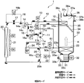
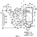
- the heat pump cycle 10 of the present disclosure is applied to the vehicle air conditioner 1 of an electric vehicle or a hybrid vehicle that obtains driving force for traveling from a traveling electric motor.
- the heat pump cycle 10 functions to cool or heat the vehicle interior air blown into the vehicle interior of the present disclosure in the vehicle air conditioner 1.
- the heat pump cycle 10 of the present embodiment is configured to dehumidify the vehicle interior with a heating mode refrigerant circuit (see FIG. 1), a cooling mode refrigerant circuit (see FIG. 5) for cooling the vehicle interior, or the vehicle interior.
- the refrigerant circuit (see FIG. 5) in the dehumidifying mode for heating is configured to be switchable.
- a refrigerant circuit in the normal heating mode described later corresponds to the first refrigerant circuit
- a refrigerant circuit in the normal cooling mode corresponds to the second refrigerant circuit.
- the refrigerant in the refrigerant circuit in the liquid reservoir mode in which the refrigerant excluding the lubricating oil is stored in the indoor evaporator 23 when the heating mode is performed, or when the heating mode is performed.
- the refrigerant shortage mode for supplying the refrigerant from the indoor evaporator 23 to the refrigerant circuit can be executed.
- FIG. 1 FIG. 5, FIG. 6, and FIG. 9, the refrigerant flow in each operation mode is indicated by a thick arrow, an arrow with hatching, a white arrow, and a solid arrow.
- the heat pump cycle 10 employs an HFC refrigerant (specifically, R134a) as the refrigerant, and constitutes a vapor compression subcritical refrigeration cycle in which the high-pressure side refrigerant pressure does not exceed the critical pressure of the refrigerant.
- HFC refrigerant specifically, R134a
- coolants for example, R1234yf.
- This refrigerant is mixed with lubricating oil as refrigerating machine oil for lubricating components such as the compression mechanism and bearings of the compressor 11, and the lubricating oil circulates in the refrigerant circuit together with the refrigerant.
- the compressor 11 is disposed in the hood of the vehicle, and inhales, compresses and discharges the refrigerant in the heat pump cycle 10.
- the compressor 11 includes two compression mechanisms, a low-stage compression mechanism and a high-stage compression mechanism, each of which is a fixed-capacity compression mechanism, and both of the compression mechanisms.
- This is a two-stage boosting type electric compressor configured to accommodate an electric motor that is driven to rotate.
- a suction port 11a that sucks low-pressure refrigerant from the outside of the housing into the low-stage compression mechanism, and an intermediate pressure where intermediate-pressure refrigerant flows from the outside of the housing into the housing and merges with the refrigerant in the compression process.
- a pressure port 11b and a discharge port 11c for discharging the high-pressure refrigerant discharged from the high-stage compression mechanism to the outside of the housing are provided.
- the intermediate pressure port 11b is connected to the refrigerant discharge port side of the low-stage compression mechanism (that is, the refrigerant suction port side of the high-stage compression mechanism).
- the compressor 11 compresses the refrigerant sucked through the suction port 11a to a refrigerant having an intermediate pressure lower than that of the high-pressure refrigerant (that is, a refrigerant in the compression process), and the compressed refrigerant and the intermediate pressure port 11b.
- the refrigerant sucked through the refrigerant is combined and compressed to a high-pressure refrigerant.
- various types such as a scroll-type compression mechanism, a vane-type compression mechanism, and a rolling piston-type compression mechanism can be adopted as the low-stage side compression mechanism and the high-stage side compressor.
- the operation of the electric motor is controlled by a control signal output from an electronic control device 40 described later (that is, the rotation speed).
- an AC synchronous motor may be employed.
- capacitance of the compressor 11 is changed by this rotation speed control.
- the compressor 11 which accommodated two compression mechanisms in one housing is employ
- adopted the format of a compressor is not limited to this.
- one fixed capacity type compression mechanism and an electric motor that rotationally drives the compression mechanism are provided inside the housing.
- An electric compressor configured to house a motor may be used.
- the inlet 12 a side of the indoor condenser 12 is connected to the discharge port 11 c of the compressor 11.
- the indoor condenser 12 is arrange
- the indoor condenser 12 is a radiator that radiates heat from the high-pressure refrigerant discharged from the high-stage compression mechanism of the compressor 11 and heats the air blown into the vehicle interior that has passed through the indoor evaporator 23 described later.
- a high-stage expansion valve 13 Connected to the outlet 12b side of the indoor condenser 12 is an inlet side of a high-stage expansion valve 13 as a high-stage decompression means that can decompress the high-pressure refrigerant flowing out of the indoor condenser 12 until it becomes an intermediate-pressure refrigerant.
- the high-stage side expansion valve 13 is an electrically variable that includes a valve element that can change the throttle opening degree and an actuator that includes a stepping motor that changes the throttle opening degree of the valve element.
- the throttle opening is the opening of the refrigerant flow path between the outlet of the indoor condenser 12 and the inlet of the gas-liquid separator 14.
- the high stage side expansion valve 13 is configured to be able to be set to a throttling state in which the refrigerant decompression action is exhibited and a fully open state in which the refrigerant decompression action is not exhibited.
- the high stage side expansion valve 13 can also close the refrigerant flow path from the outdoor heat exchanger 20 to the indoor evaporator 23 with the throttle opening fully closed.
- the operation of the high stage side expansion valve 13 is controlled by a control signal output from the electronic control unit 40.
- a gas-liquid separator 14 as a separator for separating the gas-liquid of the intermediate pressure refrigerant flowing out of the indoor condenser 12 and decompressed by the high stage expansion valve 13.
- a refrigerant inflow port is connected.
- the gas-liquid separator 14 of this embodiment is a centrifugal separator that separates the refrigerant sucked from the refrigerant inflow port into “a gas-phase refrigerant excluding lubricating oil” and “the remaining refrigerant including lubricating oil” by the action of centrifugal force. Separation method.
- a type other than the centrifugal separation type may be used.
- the gas-liquid separator 14 is provided with a gas-phase refrigerant outflow port 14a through which the gas-phase refrigerant excluding lubricating oil flows out.
- an intermediate pressure port 11 b of the compressor 11 is connected to the gas phase refrigerant outlet port 14 a via an intermediate pressure refrigerant passage 15.
- An intermediate pressure side opening / closing valve 16 a is disposed in the intermediate pressure refrigerant passage 15.
- the intermediate pressure side opening / closing valve 16 a is an electromagnetic valve that opens and closes the intermediate pressure refrigerant passage 15, and its operation is controlled by a control signal output from the electronic control device 40.
- the intermediate pressure side opening / closing valve 16a only allows the refrigerant to flow from the gas phase refrigerant outlet port 14a of the gas-liquid separator 14 to the intermediate pressure port 11b side of the compressor 11 when the intermediate pressure refrigerant passage 15 is opened. It also functions as a check valve. This prevents the refrigerant from flowing back from the compressor 11 side to the gas-liquid separator 14 when the intermediate pressure side on-off valve 16a opens the intermediate pressure refrigerant passage 15.
- the intermediate pressure side opening / closing valve 16 a functions to switch the cycle configuration (that is, the refrigerant flow path) by opening and closing the intermediate pressure refrigerant passage 15.
- the gas-liquid separator 14 is provided with a liquid phase refrigerant outflow port 14c through which the remaining refrigerant liquid phase refrigerant containing the lubricating oil flows out.
- the liquid-phase refrigerant outflow port 14c of the gas-liquid separator 14 is connected to the inlet side of the low-stage decompression section that can decompress the remaining liquid-phase refrigerant including the lubricating oil, and is connected to the outlet side of the low-stage decompression section.
- the inlet side of the outdoor heat exchanger 20 is connected.
- the low-stage decompression section of the present embodiment is configured to include a low-stage fixed throttle 17, a fixed throttle bypass passage 18, and a low-pressure side opening / closing valve 16b.
- the low-stage fixed throttle 17 reduces the pressure of the refrigerant flowing out from the liquid-phase refrigerant outflow port 14c of the gas-liquid separator 14 until it becomes a low-pressure refrigerant.
- the fixed throttle bypass passage 18 guides the refrigerant flowing out from the liquid-phase refrigerant outflow port 14c of the gas-liquid separator 14 to the outdoor heat exchanger 20 side by bypassing the low-stage fixed throttle 17.
- the low pressure side opening / closing valve 16b is a passage opening / closing valve for opening / closing the fixed throttle bypass passage 18.
- the basic configuration of the low pressure side on / off valve 16b is the same as that of the intermediate pressure side on / off valve 16a, and is an electromagnetic valve whose opening / closing operation is controlled by a control voltage output from the electronic control unit 40.
- the pressure loss that occurs when the refrigerant passes through the low-pressure side on-off valve 16 b is extremely small with respect to the pressure loss that occurs when the refrigerant passes through the low-stage side fixed throttle 17. Therefore, the refrigerant flowing out of the indoor condenser 12 flows into the outdoor heat exchanger 20 via the fixed throttle bypass passage 18 when the low-pressure side on-off valve 16b is open, and the low-pressure side on-off valve 16b is closed. If it is, it flows into the outdoor heat exchanger 20 through the low stage side fixed throttle 17.
- the low-stage decompression unit can be changed between a throttle state that exhibits a decompression action and a fully open state that does not exhibit a decompression action by opening and closing the low-pressure side on-off valve 16b.
- the three-way valve includes a refrigerant circuit that connects the liquid-phase refrigerant outlet port 14c outlet side of the gas-liquid separator 14 and the low-stage fixed throttle 17 inlet side, and the liquid-phase refrigerant outlet port 14c outlet side and the fixed throttle bypass passage 18. Switch the refrigerant circuit connecting the inlet side.
- the outdoor heat exchanger 20 shown in FIG. 1 is arranged in the bonnet and exchanges heat between the low-pressure refrigerant circulating inside and the outside air blown from the blower fan 21.
- the outdoor heat exchanger 20 functions as an evaporator that evaporates the low-pressure refrigerant and exerts an endothermic action from the outside air during the heating mode described later, and functions as a radiator that radiates the high-pressure refrigerant to the outside air in the cooling mode.
- Heat exchanger Furthermore, the outdoor heat exchanger 20 functions in a dehumidification mode as a radiator that radiates heat from the high-pressure refrigerant to the outside air or a heat absorber that absorbs heat from the outside air.
- the inlet side of the cooling expansion valve 22 is connected to the outlet side of the outdoor heat exchanger 20.
- the cooling expansion valve 22 decompresses the refrigerant flowing from the outlet of the outdoor heat exchanger 20 to the inlet of the indoor evaporator 23 when the cooling mode is performed.
- the cooling expansion valve 22 is an electric variable throttle mechanism configured in the same manner as the high stage side expansion valve 13.
- the cooling expansion valve 22 is configured to be able to be set to a throttled state in which the refrigerant pressure-reducing action is exhibited, a fully-open state in which the refrigerant pressure-reducing action is not exerted, and a fully-closed state in which the throttle opening is fully closed.
- the throttle opening is the opening of the refrigerant flow path between the outlet of the outdoor heat exchanger 20 and the inlet of the indoor evaporator 23.
- the operation of the cooling expansion valve 22 is controlled by a control signal output from the electronic control unit 40.
- the inlet side 23 a of the indoor evaporator 23 is connected to the outlet side of the cooling expansion valve 22.
- the indoor evaporator 23 is disposed in the air conditioning case 31 of the indoor air conditioning unit 30 on the upstream side of the air flow in the vehicle interior of the indoor condenser 12.
- the indoor evaporator 23 is an evaporator that cools the air blown into the vehicle interior by evaporating the refrigerant that circulates in the dehumidifying mode or the like in the dehumidifying mode or the like and exerting a heat absorbing action in the cooling mode.
- the inlet side of the accumulator 24 is connected to the outlet 23 b side of the indoor evaporator 23 via the refrigerant flow path 51.
- the accumulator 24 separates the refrigerant flowing into the gas phase refrigerant and the liquid phase refrigerant and stores the liquid phase refrigerant as an excess refrigerant.
- the suction port 11 a of the compressor 11 is connected to the gas phase refrigerant outlet of the accumulator 24. Therefore, the accumulator 24 is connected so that the gas-phase refrigerant flows out to the suction port 11a side of the compressor 11.
- an expansion valve bypass passage 25 that guides the refrigerant flowing out of the outdoor heat exchanger 20 to the inlet side of the accumulator 24 by bypassing the cooling expansion valve 22 and the indoor evaporator 23. Is connected.
- An outlet 25 a of the expansion valve bypass passage 25 is connected to the refrigerant flow path 51.
- a cooling on-off valve 16c for opening and closing the expansion valve bypass passage 25 is disposed.
- the refrigerant flow path 51 is a refrigerant flow path that connects between the outlet 23 b of the indoor evaporator 23 and the inlet of the accumulator 24.
- the basic configuration of the cooling on-off valve 16c is the same as that of the intermediate pressure side on-off valve 16a, and is an electromagnetic valve whose opening / closing operation is controlled by the control voltage output from the electronic control unit 40. Further, the pressure loss that occurs when the refrigerant passes through the cooling on-off valve 16 c is extremely small compared to the pressure loss that occurs when the refrigerant passes through the cooling expansion valve 22. Therefore, the refrigerant flowing out of the outdoor heat exchanger 20 flows into the accumulator 24 through the expansion valve bypass passage 25 when the cooling on-off valve 16c is open.
- the intermediate pressure refrigerant passage 15 and the indoor evaporator are bypassed by bypassing the low stage side fixed throttle 17, the fixed throttle bypass passage 18, the low pressure side on-off valve 16b, the outdoor heat exchanger 20, and the cooling expansion valve 22.
- a bypass passage 50 is provided to connect the outlet 23b of the 23.
- the inlet 50 a of the bypass passage 50 is connected between the outlet of the intermediate pressure side on-off valve 16 a and the intermediate pressure port 11 b of the compressor 11 in the intermediate pressure refrigerant passage 15.
- the outlet 50 b of the bypass passage 50 is connected between the outlet 23 b of the indoor evaporator 23 and the inlet of the frost prevention expansion valve 61 in the refrigerant flow path 51.
- a refrigerant reservoir opening / closing valve 60 is disposed between the inlet 50 a and the outlet 50 b in the bypass passage 50.
- the refrigerant reservoir opening / closing valve 60 is an electromagnetic valve that opens and closes the bypass passage 50, and its operation is controlled by a control signal output from the electronic control device 40.
- a frost prevention expansion valve 61 is connected between the refrigerant passage 51 and the outlet 50 b side of the bypass passage 50 and the outlet 25 a side of the expansion valve bypass passage 25.
- the frost prevention expansion valve 61 is an electric variable throttle mechanism configured in the same manner as the high stage side expansion valve 13 and the cooling expansion valve 22.
- the frost prevention expansion valve 61 is configured to be able to be set to a throttled state in which the refrigerant decompression action is exhibited, a fully open state in which the refrigerant decompression action is not exhibited, and a fully closed state in which the throttle opening is fully closed.
- the throttle opening is the opening of the refrigerant flow path between the outlet 23 b of the indoor evaporator 23 and the inlet of the accumulator 24.
- the operation of the frost prevention expansion valve 61 is controlled by a control signal output from the electronic control unit 40.
- the indoor air conditioning unit 30 is disposed inside the instrument panel (ie, the instrument panel) at the foremost part of the vehicle interior to form the outer shell of the indoor air conditioning unit 30.
- the indoor air conditioning unit 30 has an air conditioning case 31.
- the air-conditioning case 31 forms an air passage for vehicle interior blown air that is blown into the vehicle interior.
- the air blower 32, the above-mentioned indoor condenser 12, the indoor evaporator 23, etc. are accommodated in this air passage.
- An inside / outside air switching device 33 is disposed on the most upstream side of the air flow in the air conditioning case 31.
- the inside / outside air switching device 33 includes an inside air introduction port 33a that introduces vehicle interior air into the air conditioning case 31, an outside air introduction port 33b that introduces outside air into the air conditioning case 31, and an inside / outside air switching that opens and closes the introduction ports 33a and 33b. And a door 33c.
- the inside / outside air switching device 33 continuously adjusts the opening area of the inside air introduction port 33a and the opening area of the outside air introduction port 33b by the inside / outside air switching door 33c, and the air volume ratio between the air volume of the inside air and the air volume of the outside air. Is continuously changed.
- a blower 32 is disposed on the downstream side of the air flow of the inside / outside air switching device 33 to blow the air sucked through the inside / outside air switching device 33 into the vehicle interior as indicated by an arrow K.
- the blower 32 is an electric blower that drives a centrifugal multiblade fan (that is, a sirocco fan) with an electric motor, and the rotation speed (that is, the amount of blown air) is controlled by a control voltage output from the electronic control unit 40.
- the indoor evaporator 23 and the indoor condenser 12 are arranged in the order of the indoor evaporator 23 and the indoor condenser 12 with respect to the flow of the air blown into the vehicle interior.
- the indoor evaporator 23 is disposed on the upstream side of the air flow with respect to the indoor condenser 12.
- a bypass passage 35 is provided in the air conditioning case 31 to flow the blown air after passing through the indoor evaporator 23, bypassing the indoor condenser 12.
- An air mix door 34 is disposed downstream of the indoor evaporator 23 and upstream of the indoor condenser 12.
- the air mix door 34 adjusts the air volume ratio between the air volume that passes through the indoor condenser 12 and the air volume that passes through the bypass passage 35 in the blown air that has passed through the indoor evaporator 23, and the heat of the indoor condenser 12. Adjust the exchange capacity.
- the air mix door 34 is driven by a servo motor (not shown) whose operation is controlled by a control signal output from the electronic control device 40.
- a merging space 36 in which the indoor blast air merges is provided.
- an opening for blowing the blown air merged in the merge space 36 into the vehicle interior, which is the air conditioning target space is arranged.
- the opening includes a defroster opening 37a that blows conditioned air toward the inner surface of the vehicle front window glass, a face opening 37b that blows conditioned air toward the upper body of the passenger in the vehicle interior, and the feet of the passenger A foot opening 37c is provided to blow conditioned air toward the front.
- the temperature of the blown air in the merge space 36 is adjusted by adjusting the air volume ratio between the air volume that allows the air mix door 34 to pass through the indoor condenser 12 and the air volume that passes through the bypass passage.
- the defroster door 38a for adjusting the opening area of the defroster opening 37a and the opening area of the face opening 37b are adjusted.
- a foot door 38c for adjusting the opening area of the face door 38b and the foot opening 37c is disposed.
- the defroster door 38a, the face door 38b, and the foot door 38c constitute an opening mode switching unit that switches the opening mode.
- the defroster door 38a, the face door 38b, and the foot door 38c are controlled by a control signal output from the electronic control unit 40 via a link mechanism or the like. It is driven by a servo motor (not shown) whose operation is controlled.
- the air flow downstream side of the defroster opening 37a, the face opening 37b and the foot opening 37c is respectively connected to a defroster outlet, a face outlet and a foot outlet provided in the vehicle interior via ducts forming an air passage. Connected to the outlet and.
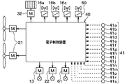
- the electronic control unit 40 includes a known microcomputer including a CPU, a ROM, a RAM, and the like and peripheral circuits thereof.
- the electronic control device 40 performs various calculations and processes based on the air conditioning control program stored in the ROM, and controls the operation of various air conditioning control devices connected to the output side.
- Various air conditioning control devices for control measures include the compressor 11, the high stage side expansion valve 13, the intermediate pressure side opening / closing valve 16a, the low pressure side opening / closing valve 16b, the cooling opening / closing valve 16c, the cooling expansion valve 22, and the refrigerant reservoir opening / closing valve. 60, a frost prevention expansion valve 61, a blower 32, and the like.
- a sensor group 41 for air conditioning control is connected to the input side of the electronic control unit 40.
- the sensor group 41 includes an inside air sensor 41a, an outside air sensor 41b, a solar radiation sensor 41c, an evaporator temperature sensor 41d, a heat exchanger temperature sensor 41e, a discharge pressure sensor 41f, a refrigerant temperature sensor 41g, 41i, 41n, and a refrigerant pressure sensor 41h. 41j, 41m, liquid level sensor 41p, superheat degree sensor 41r, heat exchanger temperature sensor 41s, and the like.
- the inside air sensor 41a detects the passenger compartment temperature.
- the outside air sensor 41b detects the outside air temperature.
- the solar radiation sensor 41c detects the amount of solar radiation in the passenger compartment.
- the evaporator temperature sensor 41d detects the temperature of air blown from the indoor evaporator 23.
- the heat exchanger temperature sensor 41e detects the temperature of air blown from the outdoor heat exchanger 20.
- the discharge pressure sensor 41 f detects the high-pressure refrigerant pressure discharged from the compressor 11.
- the refrigerant temperature sensor 41g detects the temperature of the outlet side refrigerant of the outdoor heat exchanger 20.
- the refrigerant pressure sensor 41 h detects the pressure of the refrigerant on the outlet side of the outdoor heat exchanger 20.
- the outlet side refrigerant of the outdoor heat exchanger 20 of the present embodiment is a refrigerant that flows between the outlet of the outdoor heat exchanger 20 and the inlet of the cooling on-off valve 16c.
- the refrigerant temperature sensor 41 i detects the temperature of the outlet side refrigerant of the indoor condenser 12.
- the refrigerant pressure sensor 41j detects the pressure of the outlet side refrigerant of the indoor condenser 12.
- the outlet side refrigerant of the indoor condenser 12 of the present embodiment is a refrigerant between the outlet of the indoor condenser 12 and the inlet of the high stage side expansion valve 13.
- the refrigerant temperature sensor 41n detects the temperature of the outlet side refrigerant of the indoor evaporator 23.
- the refrigerant pressure sensor 41m detects the pressure of the refrigerant on the outlet side of the indoor evaporator 23.
- the outlet side refrigerant of the indoor evaporator 23 according to the present embodiment is a refrigerant between the outlet of the indoor evaporator 23 and the inlet of the accumulator 24.
- the liquid level sensor 41p detects the liquid level height of the liquid phase refrigerant in the accumulator 24.
- the superheat degree sensor 41r detects the degree of superheat of the refrigerant discharged from the compressor 11.
- the heat exchanger temperature sensor 41 s detects the temperature of the blown air blown from the indoor condenser 12.
- an operation panel (not shown) disposed near the instrument panel in the front part of the vehicle interior is connected to the input side of the electronic control unit 40, and operation signals from various air conditioning operation switches provided on the operation panel are input.
- the vehicle interior temperature setting switch sets a set temperature Tset as a target temperature of the vehicle interior temperature.
- the operation selection switch selects a cooling mode, a heating mode, a dehumidifying mode, or the like.
- the electronic control unit 40 is configured integrally with a control unit that controls the operation of various air conditioning control devices connected to the output side thereof.
- operation of each control object apparatus comprises the control part which controls the action
- the configuration that controls the operation of the electric motor of the compressor 11 constitutes the discharge capacity control unit.
- a configuration (that is, hardware and software) that controls the operation of the refrigerant flow switching means 16a to 16c constitutes the refrigerant flow control unit.
- the discharge capacity control unit and the refrigerant flow path control unit may be configured as separate control devices for the electronic control device 40.
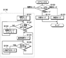
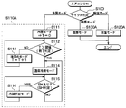
- FIG. 3 is a flowchart showing the air conditioning control process of the electronic control unit 40.
- the electronic control unit 40 executes the air conditioning control process according to the flowchart of FIG.
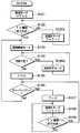
- step 100 based on the detected temperature of the outside air sensor 41b and the set temperature Tset, an operation mode to be executed among the cooling mode, the heating mode, and the dehumidifying mode is determined.
- the cooling mode is determined.
- the dehumidifying mode is determined.
- the heating mode is determined when the outside air temperature is lower than the predetermined temperature.
- an operation mode to be executed is determined among the cooling mode, the heating mode, and the dehumidification mode in accordance with the operation of the operation selection switch by the user.
- the cooling mode is determined as the operation mode to be executed in step 100
- the cooling mode is executed in step 110.
- the dehumidifying mode is executed in step 120.
- the counter is a counter that counts the time during which the liquid storage mode described later is continuously executed.
- step 132 it is determined whether or not the count value T of the counter has reached the threshold value.
- the threshold value is a value corresponding to a predetermined time required to store a predetermined amount of surplus refrigerant in the indoor evaporator 23, and is determined in advance by experiments or the like.
- the liquid storage mode is a mode in which the vehicle interior blown air is heated by the indoor condenser 12 while storing the vapor phase refrigerant excluding the lubricating oil in the indoor evaporator 23.
- the gas-phase refrigerant in the indoor evaporator 23 is cooled and condensed by the air blown into the vehicle interior to become a liquid-phase refrigerant, and the liquid-phase refrigerant is stored in the indoor evaporator 23.
- Step 132 the process returns to step 132. For this reason, until the count value T of the counter reaches the threshold value, the NO determination at step 132, the execution of the liquid reservoir mode, and the increment of the count value T of the counter at step 133 are repeated. Thereafter, when the execution time of the liquid reservoir mode becomes equal to or longer than the predetermined time and the count value T of the counter becomes equal to or greater than the threshold value, it is determined as YES in Step 132.
- the liquid storage mode is continuously performed for a predetermined period before the normal heating mode is executed. For this reason, a predetermined amount of liquid refrigerant is stored in the indoor evaporator 23 before the normal heating mode is executed.
- the normal heating mode is a mode in which the vehicle interior air is heated by the indoor condenser 12 in a state where a predetermined amount of refrigerant is accumulated in the indoor evaporator 23.
- the outdoor heat exchanger 20 functions as an evaporator that evaporates the refrigerant by heat exchange between the refrigerant and the outside air.
- the amount of refrigerant in the refrigerant circuit in the normal heating mode is insufficient, the gas phase region where the gas phase refrigerant exists in the outdoor heat exchanger 20 increases. For this reason, the outdoor heat exchanger 20 cannot exhibit a sufficient function as an evaporator for evaporating the refrigerant.
- step 135 it is determined whether or not the refrigerant amount in the refrigerant circuit in the normal heating mode is greater than or equal to the necessary refrigerant amount.
- the required amount of refrigerant is the amount of refrigerant that is necessary for exhibiting sufficient heating capacity in the indoor condenser 12 when the normal heating mode is performed.
- the required amount of refrigerant is the refrigerant that needs to be present in the first refrigerant circuit in order to heat the air flow in the first indoor heat exchanger 12 by circulating the refrigerant in the first refrigerant circuit. Amount.
- the degree of superheat of the refrigerant on the outlet side of the outdoor heat exchanger 20 is calculated based on the detected pressure of the refrigerant pressure sensor 41h and the detected temperature of the refrigerant temperature sensor 41g. And it is determined whether the superheat degree of the refrigerant
- the refrigerant on the outlet side of the outdoor heat exchanger 20 is a refrigerant between the outlet of the outdoor heat exchanger 20 and the inlet of the cooling on-off valve 16c.
- step 135. it is determined that the refrigerant amount in the refrigerant circuit in the normal heating mode is less than the necessary refrigerant amount. Accordingly, in step 136, the refrigerant shortage mode for returning the refrigerant from the indoor condenser 12 to the refrigerant circuit in the normal heating mode is executed.
- step 135 determines whether or not the amount of refrigerant in the refrigerant circuit in the normal heating mode is greater than or equal to the necessary amount of refrigerant. Therefore, the YES determination in step 135 and the refrigerant shortage mode (step 136) are repeated until the refrigerant amount in the refrigerant circuit in the normal heating mode becomes equal to or greater than the necessary refrigerant amount.
- the process returns to step 134 and the normal heating mode is performed.
- the normal heating mode is executed.
- the refrigerant amount in the refrigerant circuit in the normal heating mode becomes less than the necessary refrigerant amount, the refrigerant shortage mode is set. Execute.
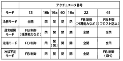
- the cooling mode, the dehumidifying mode, the normal heating mode, the liquid reservoir mode, and the refrigerant shortage mode will be described separately.
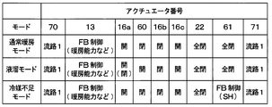
- the electronic control unit 40 opens the frost prevention expansion valve 61, opens the high-stage expansion valve 13 in a fully open state where the pressure reducing action is not exerted, and restricts the cooling expansion valve 22 to exert the pressure reducing action. And the cooling on-off valve 16c is closed.
- the low-pressure side opening / closing valve 16b is opened, the low-stage pressure reducing means is fully opened without exerting a pressure reducing action, and the intermediate pressure-side opening / closing valve 16a is closed in conjunction with the state of the low-pressure side opening / closing valve 16b.
- the heat pump cycle 10 is switched to the refrigerant flow path through which the refrigerant flows as shown by the thick arrows in FIG.
- the electronic control device 40 reads the detection signals of the sensors 41a, 41b, 41c and the operation signal of the operation panel. And the target blowing temperature TAO which is the target temperature of the blowing air which blows off into a vehicle interior is calculated based on the value of a detection signal and an operation signal.
- the target blowing temperature TAO is a temperature required for the detected temperature of the inside air sensor 41a to maintain the set temperature Tset as the air temperature blown out from the openings 37a, 37b, 37c into the vehicle interior.
- the operating states of various air conditioning control devices connected to the output side of the electronic control unit 40 are determined based on the target blowing temperature TAO and the detection signal of the sensor group.
- the control signal for controlling the refrigerant discharge capacity of the compressor 11, that is, the rotational speed of the electric motor of the compressor 11, is determined as follows. First, the target evaporator outlet temperature TEO of the indoor evaporator 23 is determined based on the target outlet temperature TAO with reference to a control map stored in the electronic control unit 40 in advance.
- the blowing air temperature from the indoor evaporator 23 is converted to the target evaporation by feedback control.
- a control signal for controlling the electric motor of the compressor 11 is determined so as to approach the compressor outlet temperature TEO.
- the throttle opening degree of the cooling expansion valve 22 is a target supercooling degree determined in advance so that the supercooling degree of the refrigerant flowing into the cooling expansion valve 22 approaches COP, that is, Coefficient of ⁇ Performance. It is decided to approach. Thereby, in the indoor evaporator 23, the cooling ability of the refrigerant to cool the air blown into the passenger compartment can be exhibited.
- the degree of supercooling is calculated based on the detected temperature of the refrigerant temperature sensor 41g and the detected pressure of the refrigerant pressure sensor 41h.
- the throttle opening degree of the expansion valve 61 for preventing frost is set so that the temperature of the indoor evaporator 23 becomes equal to or higher than a threshold value in order to avoid the generation of frost in the indoor evaporator 23.
- the throttle opening of the frost prevention expansion valve 61 is set based on the temperature detected by the evaporator temperature sensor 41d.
- the air mix door 34 closes the air passage of the indoor condenser 12, and the entire flow rate of the blown air after passing through the indoor evaporator 23 passes through the bypass passage 35. To be determined.
- control signals determined as described above are output to various air conditioning control devices.
- the above detection signal and operation signal are read, the target blowing temperature TAO is calculated, and the operating state of various air conditioning control devices is determined at every predetermined control cycle.
- the control routine such as the output of the control voltage and the control signal is repeated in this order. Such a control routine is repeated in the other operation modes.
- the high-pressure refrigerant discharged from the discharge port 11 c of the compressor 11 flows into the indoor condenser 12.
- the air mix door 34 closes the air passage of the indoor condenser 12
- the refrigerant flowing into the indoor condenser 12 flows out of the indoor condenser 12 without radiating heat to the vehicle interior air.
- the refrigerant that has flowed out of the indoor condenser 12 flows in the order of the high-stage expansion valve 13, the gas-liquid separator 14, and the low-pressure side opening / closing valve 16 b and flows into the outdoor heat exchanger 20. More specifically, the refrigerant that has flowed out of the indoor condenser 12 flows out almost without being depressurized by the high stage side expansion valve 13 because the high stage side expansion valve 13 is fully open, and is separated into gas and liquid. It flows into the gas-liquid separator 14 from the refrigerant inflow port of the condenser 14.
- the refrigerant flowing into the gas-liquid separator 14 is in a gas phase state having a superheat degree. Therefore, in the gas-liquid separator 14, the refrigerant flows out from the liquid phase refrigerant outflow port 14c as a gas phase refrigerant without being separated into the gas phase refrigerant and the liquid phase refrigerant. Further, since the intermediate pressure side opening / closing valve 16a is in the closed state, the gas phase refrigerant does not flow out from the gas phase refrigerant outflow port.
- the refrigerant that has flowed out of the outdoor heat exchanger 20 flows into the cooling expansion valve 22 because the cooling on-off valve 16c is closed. For this reason, the refrigerant flowing out of the outdoor heat exchanger 20 is decompressed and expanded in an enthalpy manner until it becomes a low-pressure refrigerant by the cooling expansion valve 22. Then, the low-pressure refrigerant decompressed by the cooling expansion valve 22 flows into the indoor evaporator 23, absorbs heat from the indoor air blown from the blower 32, and evaporates. Thereby, vehicle interior blowing air is cooled.
- the refrigerant that has flowed out of the indoor evaporator 23 flows into the accumulator 24 through the frost prevention expansion valve 61 and is separated into a gas-phase refrigerant and a liquid-phase refrigerant by the accumulator 24.
- the separated gas-phase refrigerant is sucked from the suction port 11a of the compressor 11 and is compressed again in this order in the low-stage compression mechanism and the high-stage compression mechanism.
- the separated liquid-phase refrigerant is stored in the accumulator 24 as surplus refrigerant that is not necessary for exhibiting the refrigerating capacity required for the cycle.
- the electronic control unit 40 reduces the throttle opening of the frost prevention expansion valve 61 and increases the refrigerant pressure in the indoor evaporator 23 to increase the indoor evaporator 23. Increase the temperature.
- the high-stage expansion valve 13, the gas-liquid separator 14, the fixed-throttle bypass passage 18, and the low-pressure that have made the refrigerant flowing out of the indoor condenser 12 fully open.
- the side opening / closing valve 16b, the outdoor heat exchanger 20, the cooling expansion valve 22, the indoor evaporator 23, the frost prevention expansion valve 61, the accumulator 24, the compressor 11, and the indoor condenser 12 are flowed in this order.
- the electronic control unit 40 When executing the dehumidification mode, the electronic control unit 40 opens the frost prevention expansion valve 61, opens the high-stage side expansion valve 13 in the fully open state or throttled state, and opens the cooling expansion valve 22 in the fully open state or throttled state. And the cooling on-off valve 16c is closed. Further, the low-pressure side opening / closing valve 16b is opened, the low-stage pressure reducing means is fully opened so that the pressure reducing action is not exerted, and the intermediate pressure-side opening / closing valve 16a is closed in conjunction with the state of the low-pressure side opening / closing valve 16b. Thereby, the heat pump cycle 10 is switched to the refrigerant flow path through which the refrigerant flows as shown by the thick arrows in FIG. 1 similar to the cooling mode.
- the throttle opening degree of the frost prevention expansion valve 61 is set so that the temperature of the indoor evaporator 23 becomes equal to or higher than a threshold value in order to avoid the generation of frost in the indoor evaporator 23
- the air mix door 34 closes the bypass passage 35, and the entire flow rate of the blown air after passing through the indoor evaporator 23 passes through the indoor condenser 12. To be determined.
- the throttle opening degree of the high stage side expansion valve 13 and the cooling expansion valve 22 is changed according to the temperature difference between the set temperature and the outside air temperature. Specifically, the throttle opening of the high-stage side expansion valve 13 is decreased and the throttle opening of the cooling expansion valve 22 is increased as the target blowout temperature TAO increases as described above.
- a four-stage dehumidifying mode is executed from the 1 dehumidifying mode to the fourth dehumidifying mode.
- the high-stage expansion valve 13 In the first dehumidifying mode, the high-stage expansion valve 13 is fully opened, and the cooling expansion valve 22 is in the throttle state. Therefore, although the cycle configuration (that is, the refrigerant flow path) is exactly the same as in the cooling mode, the air mix door 34 fully opens the air passage of the indoor condenser 12.
- the high-pressure refrigerant discharged from the discharge port 11c of the compressor 11 flows into the indoor condenser 12 and dissipates heat by exchanging heat with the vehicle interior blown air cooled and dehumidified by the indoor evaporator 23. . Thereby, vehicle interior blowing air is heated.
- the refrigerant flowing out of the indoor condenser 12 flows in the order of the high stage expansion valve 13, the gas-liquid separator 14, and the low pressure side opening / closing valve 16b of the low stage side decompression means to the outdoor heat exchanger 20 in the same manner as in the cooling mode. Inflow.
- the low-pressure refrigerant that has flowed into the outdoor heat exchanger 20 exchanges heat with the outside air blown from the blower fan 21 to radiate heat.
- the subsequent operation is the same as in the normal cooling mode.
- the vehicle interior air cooled and dehumidified by the indoor evaporator 23 can be heated by the indoor condenser 12 and blown out into the vehicle interior. Thereby, dehumidification heating of a vehicle interior is realizable.
- the second dehumidifying mode is executed.
- the third dehumidifying mode is executed.
- the fourth dehumidifying mode is executed when the target blowing temperature TAO becomes higher than the predetermined third reference temperature. Since the second, third, and fourth dehumidifying modes are the same as the technical contents described in Patent Document 1, description of the second, third, and fourth dehumidifying modes is omitted.
- the electronic control unit 40 controls the rotation speed of the electric motor of the compressor 11 (that is, the refrigerant discharge capacity of the compressor 11) based on the target outlet temperature TAO. For example, based on the deviation, a control signal for controlling the electric motor of the compressor 11 is determined so that the temperature of the air blown from the indoor condenser 12 approaches the target air temperature TAO by feedback control. This deviation is a deviation between the target blowing temperature TAO and the blowing air temperature from the indoor condenser 12 detected by the heat exchanger temperature sensor 41s.
- the electronic control unit 40 controls the throttle opening degree in the high stage side expansion valve 13 to bring the high stage side expansion valve 13 into a throttled state that exerts the decompression action of the refrigerant.
- the throttle opening degree of the high stage side expansion valve 13 is determined so that the degree of supercooling of the refrigerant flowing from the indoor condenser 12 to the high stage side expansion valve 13 is determined in advance so that the COP approaches the maximum value. It is decided to approach.
- coolant can exhibit the heating capability which heats vehicle interior ventilation air.
- the degree of supercooling is calculated based on the detected temperature of the refrigerant temperature sensor 41i and the detected pressure of the refrigerant pressure sensor 41j.
- the electronic control unit 40 sets the frost prevention expansion valve 61 and the cooling expansion valve 22 to a fully closed state, opens the cooling on-off valve 16c, and closes the low-pressure side on-off valve 16b to a low-stage pressure reduction.
- the means is in a throttled state that exerts a pressure reducing action.
- the electronic control unit 40 opens the intermediate pressure side opening / closing valve 16a in conjunction with the state of the low pressure side opening / closing valve 16b.
- the electronic control unit 40 controls the refrigerant reservoir opening / closing valve 60 to close the bypass passage 50.
- the heat pump cycle 10 is switched to the refrigerant flow path through which the refrigerant flows as shown by the thick arrows in FIG.
- the air mix door 34 closes the bypass passage 35 so that the entire flow rate of the blown air after passing through the indoor evaporator 23 passes through the indoor condenser 12. To be determined.
- the high-pressure refrigerant discharged from the discharge port 11 c of the compressor 11 flows into the indoor condenser 12.
- the refrigerant that has flowed into the indoor condenser 12 exchanges heat with the vehicle interior blown air that has been blown from the blower 32 and passed through the indoor evaporator 23 to dissipate heat. Thereby, vehicle interior blowing air is heated.
- the refrigerant that has flowed out of the indoor condenser 12 is decompressed and expanded in an enthalpy manner until it becomes an intermediate pressure refrigerant by the high-stage expansion valve 13 that is in a throttled state. Then, the intermediate pressure refrigerant decompressed by the high stage side expansion valve 13 is separated in the gas-liquid separator 14 into a gas phase refrigerant from which the lubricating oil has been removed and a liquid phase refrigerant containing the lubricating oil.
- the gas-phase refrigerant separated by the gas-liquid separator 14 (that is, the gas-phase refrigerant from which the lubricating oil has been removed) is opened via the intermediate-pressure refrigerant passage 15 because the intermediate-pressure side on-off valve 16a is open. Then, the refrigerant flows into the intermediate pressure port 11b of the compressor 11, merges with the refrigerant discharged from the low-stage compression mechanism, and is sucked into the high-stage compression mechanism.
- the liquid refrigerant containing the lubricating oil separated by the gas-liquid separator 14 is decompressed until it becomes a low-pressure refrigerant by the low-stage decompression means because the low-stage decompression means is in the throttle state. It flows out and flows into the outdoor heat exchanger 20. That is, in the low stage pressure reducing means, the low pressure side opening / closing valve 16b is in the closed state, so that it is decompressed and expanded in an enthalpy manner until it flows into the low stage fixed throttle 17 and becomes a low pressure refrigerant. The refrigerant that has flowed out of the low stage side fixed throttle 17 flows into the outdoor heat exchanger 20 and exchanges heat with the outside air blown from the blower fan 21 to absorb heat.
- the refrigerant flowing out of the outdoor heat exchanger 20 flows into the accumulator 24 through the expansion valve bypass passage 25 and is separated into gas and liquid because the cooling on-off valve 16c is in the open state.
- the separated gas-phase refrigerant is sucked from the suction port 11a of the compressor 11 and compressed again.
- the separated liquid-phase refrigerant is stored in the accumulator 24 as surplus refrigerant that is not necessary for exhibiting the refrigerating capacity required for the cycle.
- the heat of the refrigerant discharged from the compressor 11 by the indoor condenser 12 can be radiated to the vehicle interior blown air, and the heated room blown air can be blown into the vehicle interior. .
- heating of a vehicle interior is realizable.
- the low-pressure refrigerant decompressed by the low-stage fixed throttle 17 is sucked from the suction port 11a of the compressor 11, and the intermediate-pressure refrigerant decompressed by the high-stage expansion valve 13 is used as the intermediate pressure port.
- 11b can be combined with the refrigerant in the pressure increasing process. That is, a gas injection cycle (that is, an economizer refrigeration cycle) can be configured.
- the compression efficiency of the high-stage compression mechanism can be improved, and both the low-stage compression mechanism and the high-stage compression mechanism can be improved.
- the pressure difference between the suction refrigerant pressure and the discharge refrigerant pressure it is possible to improve the compression efficiency of both compression mechanisms.
- the COP of the heat pump cycle 10 as a whole can be improved.
- the refrigerant flowing out of the indoor condenser 12 is the high-stage expansion valve 13, the gas-liquid separator 14, and the low-stage side in the constricted state.
- a refrigerant circuit that flows in the order of the decompression means, the outdoor heat exchanger 20, the cooling on-off valve 16c, the accumulator 24, the compressor 11, and the indoor condenser 12 is configured.
- the gas-phase refrigerant separated by the gas-liquid separator 14 flows into the intermediate pressure refrigerant passage 15 and the intermediate pressure port 11 b of the compressor 11.
- the electronic control unit 40 like the normal heating mode, the high stage side expansion valve 13, the cooling expansion valve 22, the cooling opening / closing valve 16c, the low pressure side opening / closing valve 16b, the intermediate pressure side opening / closing valve 16a, and the frost prevention.
- Each expansion valve 61 is controlled.
- the high stage side expansion valve 13 is in the throttle state, the cooling expansion valve 22 is fully closed, and the cooling on-off valve 16c is opened. Further, the low pressure side on / off valve 16b is closed and the low stage pressure reducing means is in a throttle state that exerts a pressure reducing action, and the intermediate pressure side on / off valve 16a is opened in conjunction with the closed state of the low pressure side on / off valve 16b. It becomes a state.
- the frost prevention expansion valve 61 is fully closed.
- the heat pump cycle 10 As a result, the heat pump cycle 10, as shown by the thick arrow in FIG. 1, causes the refrigerant flowing out of the indoor condenser 12 to be in the throttled state, the high stage side expansion valve 13, the gas-liquid separator 14, and the low level in the throttled state.
- the stage side pressure reducing means, the outdoor heat exchanger 20, the cooling on-off valve 16c, and the accumulator 24 are flowed in this order.
- the heat pump cycle 10 converts the gas-phase refrigerant separated by the gas-liquid separator 14 into the intermediate pressure refrigerant passage 15, the intermediate pressure side on-off valve 16 a, and the intermediate pressure of the compressor 11, as indicated by the thick arrows in FIG. It flows into the port 11b.
- the electronic control unit 40 opens the refrigerant reservoir opening / closing valve 60.
- the temperature of the indoor evaporator 23 is equal to the temperature of the air blown into the passenger compartment, and the pressure in the indoor evaporator 23 is lower than the refrigerant pressure in the intermediate pressure refrigerant passage 15. For this reason, some of the gas-phase refrigerant that has passed through the intermediate-pressure side on-off valve 16a flows to the intermediate-pressure port 11b of the compressor 11, but the remaining gas-phase refrigerant is supplied from the bypass passage 50, the refrigerant accumulation on-off valve. 60, and flows into the indoor evaporator 23 through the outlet 23b of the indoor evaporator 23.
- the gas-phase refrigerant is cooled by the air blown into the passenger compartment to become a liquid-phase refrigerant. For this reason, in the indoor evaporator 23, an excess refrigerant
- coolant is stored as a liquid phase refrigerant
- the air blown into the vehicle interior is heated by the refrigerant in the indoor condenser 12, and the excess refrigerant is stored in the indoor evaporator 23 as a liquid phase refrigerant.
- the electronic control unit 40 like the normal heating mode, the high stage side expansion valve 13, the cooling expansion valve 22, the cooling on / off valve 16c, the low pressure side on / off valve 16b, the intermediate pressure side on / off valve 16a, and the refrigerant
- the reservoir open / close valve 60 is controlled. For this reason, the high stage side expansion valve 13 is in the throttle state, the cooling expansion valve 22 is fully closed, and the cooling on-off valve 16c is opened.
- the low pressure side on / off valve 16b is closed and the low stage pressure reducing means is in a throttle state that exerts a pressure reducing action, and the intermediate pressure side on / off valve 16a is opened in conjunction with the closed state of the low pressure side on / off valve 16b.
- the refrigerant reservoir opening / closing valve 60 is closed.
- the heat pump cycle 10 As a result, the heat pump cycle 10, as shown by the thick arrow in FIG. 1, causes the refrigerant flowing out of the indoor condenser 12 to be in the throttled state, the high stage side expansion valve 13, the gas-liquid separator 14, and the low level in the throttled state.
- the stage side pressure reducing means, the outdoor heat exchanger 20, the cooling on-off valve 16c, the accumulator 24, the compressor 11, and the indoor condenser 12 are flowed in this order.
- the heat pump cycle 10 converts the gas-phase refrigerant separated by the gas-liquid separator 14 into the intermediate pressure refrigerant passage 15, the intermediate pressure side on-off valve 16 a, and the intermediate pressure of the compressor 11, as indicated by the thick arrows in FIG. It flows into the port 11b.
- the electronic control unit 40 sets the throttle opening of the frost prevention expansion valve 61 to a predetermined opening. For this reason, the liquid-phase refrigerant in the indoor evaporator 23 flows to the accumulator 24 through the outlet 23 b of the indoor evaporator 23, the frost prevention expansion valve 61, and the refrigerant flow path 51 as indicated by hatched arrows. Thereby, the refrigerant
- the vehicle interior air is heated by the refrigerant in the indoor condenser 12 and the amount of refrigerant in the refrigerant circuit is increased.
- the heat pump cycle 10 of the vehicle air conditioner 1 of the present embodiment described above includes a compressor 11, an indoor condenser 12, a gas-liquid separator 14, an outdoor heat exchanger 20, a high stage side expansion valve 13, and a cooling expansion valve. 22 and an accumulator 24.
- the compressor 11 compresses the low-pressure refrigerant sucked from the suction port 11a and discharges it as a high-pressure refrigerant.
- the indoor condenser 12 heats the air flow blown toward the vehicle interior with a high-pressure refrigerant.
- the gas-liquid separator 14 separates the gas-phase refrigerant from which the lubricating oil is removed from the high-pressure refrigerant and the remaining refrigerant other than the gas-phase refrigerant.
- the outdoor heat exchanger 20 exchanges heat between the remaining refrigerant flowing out of the gas-liquid separator 14 and the outside air.
- the indoor evaporator 23 cools the air flow with the refrigerant that has passed through the outdoor heat exchanger 20.
- the high stage side expansion valve 13 controls the throttle opening degree of the refrigerant flow path between the outlet of the indoor condenser 12 and the inlet of the gas-liquid separator 14.
- the cooling expansion valve 22 controls the throttle opening degree of the refrigerant flow path between the outlet of the outdoor heat exchanger 20 and the inlet of the indoor evaporator 23.
- the accumulator 24 supplies a gas-phase refrigerant containing lubricating oil to the compressor 11 while storing a liquid-phase refrigerant out of the refrigerant discharged from the indoor evaporator 23.
- the throttle opening is controlled so that the refrigerant is decompressed in the high stage side expansion valve 13.
- the refrigerant circuit includes a compressor 11, an indoor condenser 12, a high stage side expansion valve 13, a gas-liquid separator 14, a low stage side fixed throttle 17, an outdoor heat exchanger 20, a cooling expansion valve 22, an indoor evaporator 23,
- the refrigerant circuit includes an expansion valve 61 for preventing frost and an accumulator 24.
- the gas phase refrigerant discharged from the gas-liquid separator 14 can be stored in the indoor evaporator 23 in a state where the indoor condenser 12 exhibits the heating capability. For this reason, the capacity
- the gas-phase refrigerant supplied from the gas-liquid separator 14 to the indoor evaporator 23 is a refrigerant obtained by removing lubricating oil from the high-pressure refrigerant in the gas-liquid separator 14. For this reason, the remaining refrigerant containing lubricating oil can be supplied to the compressor 11. Therefore, it can suppress that the lubricating oil supplied to the compressor 11 runs short.
- the refrigerant having an intermediate pressure higher than the atmospheric pressure is supplied to the indoor evaporator 23 in the heating mode, a predetermined amount of refrigerant can be stored in the indoor evaporator 23 in a short time.
- the atmospheric pressure is the pressure in the indoor evaporator 23 determined by the ambient temperature of the indoor evaporator 23.
- step 100 when it is determined in step 100 that the heating mode should be performed, the liquid storage mode in step 133 is performed over a certain period. For this reason, surplus refrigerant can be reliably stored in the indoor evaporator 23.
- the refrigerant shortage mode is implemented in step 136 and the refrigerant is returned from the indoor evaporator 23 to the accumulator 24. be able to. For this reason, normal heating mode can be implemented normally.
- the heating mode in which the refrigerant is circulated in the refrigerant circuit while the refrigerant is accumulated in the indoor evaporator 23 has been described.
- the indoor condensation is performed.
- the cooling mode is executed in a state where the liquid-phase refrigerant is stored in the cooler 12 will be described.
- the refrigerant circuit in the normal heating mode corresponds to the first refrigerant circuit
- the refrigerant circuit in the normal cooling mode corresponds to the second refrigerant circuit.
- FIG. 6 is a diagram showing an overall configuration of the heat pump cycle 10 of the second embodiment.
- the same reference numerals as those in FIG. 1 denote the same components.
- the heat pump cycle 10 of the present embodiment is obtained by adding three-way valves 70 and 71 to the heat pump cycle 10 of the first embodiment.
- the three-way valve 70 includes an inlet 70a and outlets 70b and 70c.
- the three-way valve 70 includes a valve body that connects between one of the outlets 70b and 70c and the inlet 70a, and opens between the other outlet and the inlet 70a, and a stepping that drives the valve body.
- An actuator such as a motor is provided.
- the inlet 70 a is connected to the discharge port 11 c of the compressor 11.
- the outlet 70 b is connected to the inlet 12 a of the indoor condenser 12.
- the outlet 70 c is connected between the outlet of the high stage side expansion valve 13 and the refrigerant inlet port of the gas-liquid separator 14.
- the three-way valve 71 includes an inlet 71a, an inlet / outlet 71b, and an inlet / outlet 71c.
- the three-way valve 71 includes a valve body and an actuator such as a stepping motor that drives the valve body.
- the valve element connects between one of the inlet / outlet port 71b and the inlet / outlet port 71c and the inlet port 71a, and opens between the other port and the inlet port 71a.
- the valve body connects between the entrance / exit 71b and the entrance / exit 71c in a state where the entrance / exit 71b and the entrance 71a are opened and the entrance / exit 71c and the entrance 71a are opened.
- the inlet 71a is connected to the outlet of the refrigerant reservoir opening / closing valve 60.
- the inlet / outlet 71b is connected between the outlet 23b of the indoor evaporator 23 and the inlet of the frost prevention expansion valve 61.
- the entrance / exit 71 c is connected to the entrance 12 a of the indoor condenser 12.
- the actuator constituting the three-way valve 70 of this embodiment and the actuator constituting the three-way valve 71 are controlled by the electronic control unit 40.
- the inlet 50 a of the bypass passage 50 is connected to the inlet side of the intermediate pressure side on-off valve 16 a in the intermediate pressure refrigerant passage 15.
- the bypass passage 50 connects the inlet 12 a of the indoor condenser 12 and the outlet 23 b of the indoor evaporator 23 via a three-way valve 71. For this reason, the bypass passage 50 bypasses the gas-liquid separator 14, the outdoor heat exchanger 20, and the indoor evaporator 23 between the inlet 12 a of the indoor condenser 12 and the inlet of the accumulator 24. Is configured.
- FIG. 7 is a flowchart showing the air conditioning control process of the electronic control unit 40. 7, the same reference numerals as those in FIG. 3 denote the same components.
- the electronic control unit 40 executes the air conditioning control process according to the flowchart of FIG.
- step 130A when the heating mode is determined as the operation mode to be executed in step 100, the heating mode is executed in step 130A.
- steps 131, 132, 133, 134, 135, and 136 are executed as in step 130 of FIG.
- step 120A when the dehumidifying mode is determined as the operation mode to be executed, the dehumidifying mode is executed in step 120A.
- the cooling mode is executed in the next step 110A.
- the counter is a counter that counts the time during which a liquid storage mode in step 113 described later is continuously executed.
- step 112 it is determined whether or not the count value T of the counter has reached a threshold value.
- the threshold value is a value corresponding to a predetermined time required to store a predetermined amount of surplus refrigerant in the indoor condenser 12, and is determined in advance by an experiment or the like.
- the liquid storage mode is a mode in which the vehicle interior air is cooled by the indoor evaporator 23 while the refrigerant is allowed to flow into the indoor condenser 12.
- the normal cooling mode is a mode in which the vehicle interior air is cooled by the indoor evaporator 23 while the refrigerant is accumulated in the indoor condenser 12.
- the indoor evaporator 23 functions as an evaporator that evaporates the refrigerant by heat exchange between the refrigerant and the indoor blown air.
- the indoor evaporator 23 cannot exhibit a sufficient function as an evaporator for evaporating the refrigerant.
- step 115 it is determined whether or not the refrigerant amount in the refrigerant circuit in the normal cooling mode is greater than or equal to the necessary refrigerant amount.
- the required amount of refrigerant is the amount of refrigerant that is required for causing the indoor evaporator 23 to exhibit sufficient cooling capacity when performing the normal cooling mode.
- the necessary amount of refrigerant is the amount of refrigerant that needs to be present in the second refrigerant circuit in order to circulate the refrigerant in the second refrigerant circuit and cool the air flow in the second indoor heat exchanger 23. It is.
- the refrigerant on the outlet side of the indoor evaporator 23 is in a superheated state having a positive superheat degree. That is, it is determined whether or not the refrigerant on the outlet side of the indoor evaporator 23 is in a gas phase state instead of a gas-liquid two-layer state.
- the degree of superheat of the refrigerant is calculated based on the detected temperature of the refrigerant temperature sensor 41n and the detected pressure of the refrigerant pressure sensor 41m.
- step 115 when the refrigerant on the outlet side of the indoor evaporator 23 is not in a gas-liquid two-layer state but in a gas phase state, YES in step 115 because the degree of superheat of the refrigerant on the outlet side of the indoor evaporator 23 is positive. judge. At this time, it is determined that the refrigerant amount in the refrigerant circuit in the normal cooling mode is less than the necessary refrigerant amount. Accordingly, in step 116, the refrigerant shortage mode for returning the refrigerant from the indoor condenser 12 into the refrigerant circuit in the normal cooling mode is executed.
- step 115 it is determined whether or not the refrigerant amount in the refrigerant circuit in the normal cooling mode is greater than or equal to the necessary refrigerant amount. Therefore, as long as the amount of refrigerant in the refrigerant circuit in the normal cooling mode is less than the necessary amount of refrigerant, the YES determination in step 115 and the refrigerant shortage mode (step 116) are repeated.
- step 115 when the refrigerant on the outlet side of the outdoor heat exchanger 20 is not in a superheated state having a positive superheat degree but in a gas-liquid two-layer state, it is determined as NO in step 115. Accordingly, the process returns to step 114.
- the normal cooling mode is executed, whereas when the refrigerant amount in the refrigerant circuit in the normal cooling mode becomes less than the necessary refrigerant amount, the refrigerant shortage mode is set. Execute.
- cooling mode in step 110A the dehumidifying mode in step 120A, and the heating mode in step 130A will be described separately.
- the normal cooling mode, the liquid reservoir mode, and the refrigerant shortage mode in the cooling mode of step 110A will be described with reference to FIGS.
- the electronic control unit 40 controls the three-way valve 70 to connect between the outlet 70c and the inlet 70a, open between the outlet 70b and the inlet 70a, and between the outlets 70b and 70c. Open. For this reason, in the three-way valve 70, the flow path 2 of FIG. 6 is formed in which the refrigerant flows from the inlet 70a to the outlet 70c.
- the electronic control unit 40 controls the three-way valve 71 to connect between the entrance / exit 71c and the entrance 71a, open between the entrance / exit 71b and the entrance 71a, and open between the entrance / exit 71c and 71b. For this reason, in the three-way valve 71, the flow path 2 of FIG. 6 is formed in which the refrigerant flows from the inlet 71a to the inlet / outlet 71c.
- the electronic control unit 40 closes the high stage side expansion valve 13.
- the electronic control unit 40 includes a cooling on / off valve 16c, a low pressure side on / off valve 16b, an intermediate pressure side on / off valve 16a, a cooling expansion valve 22, a refrigerant reservoir on / off valve 60, and The frost prevention expansion valve 61 is controlled.
- the high-pressure refrigerant discharged from the compressor 11 bypasses the fixed throttle between the outlet 70c and the inlet 70a of the three-way valve 70, between the refrigerant inlet port and the liquid-phase refrigerant outlet port 14c of the gas-liquid separator 14. It flows into the outdoor heat exchanger 20 through the passage 18 and the low-pressure side on-off valve 16b in this order. In the outdoor heat exchanger 20, the high-pressure refrigerant is cooled by outside air blown from the blower fan 21.
- the high-pressure refrigerant flowing from the outdoor heat exchanger 20 flows to the cooling expansion valve 22.
- the high-pressure refrigerant is depressurized to become a low-pressure refrigerant.
- the low-pressure refrigerant flows through the indoor evaporator 23, the frost prevention expansion valve 61, and the accumulator 24 in this order to the suction port 11a of the compressor 11.
- the refrigerant cools the indoor blown air.
- the vehicle interior blown air can be cooled by the refrigerant in the indoor condenser 12 in a state where the excess refrigerant is stored as the liquid phase refrigerant in the indoor condenser 12.
- the electronic control unit 40 In the liquid reservoir mode, the electronic control unit 40, as in the normal cooling mode, has the three-way valves 70 and 71, the high stage side expansion valve 13, the cooling expansion valve 22, the intermediate pressure side switching valve 16a, the cooling switching valve 16c, the low pressure The side opening / closing valve 16b and the frost prevention expansion valve 61 are controlled.
- the high-pressure refrigerant discharged from the compressor 11 is the flow path 2 of the three-way valve 70, the refrigerant inflow port of the gas-liquid separator 14, and the liquid phase refrigerant.
- the outflow port 14c the fixed throttle bypass passage 18, the low-pressure side opening / closing valve 16b, the outdoor heat exchanger 20, the cooling expansion valve 22, the indoor evaporator 23, the frost prevention expansion valve 61, the accumulator 24, and the compressor 11 It flows in the order of the suction port 11a.
- the electronic control unit 40 opens the refrigerant reservoir opening / closing valve 60. At this time, in the three-way valve 71, the flow path 2 through which the refrigerant flows from the inlet 71a to the inlet / outlet 71c is formed.
- the refrigerant flows into the gas-liquid separator 14 from the compressor 11 by bypassing the indoor condenser 12.
- the refrigerant that flows into the gas-liquid separator 14 from the compressor 11 through the three-way valve 70 is a gas-phase refrigerant.
- the gas-phase refrigerant flowing from the compressor 11 through the three-way valve 70 is separated into the gas-phase refrigerant excluding lubricating oil and the remaining refrigerant other than the gas-phase refrigerant. .
- the gas-phase refrigerant from which the lubricating oil has been removed flows from the gas-phase refrigerant outflow port of the gas-liquid separator 14 to the bypass passage 50.
- the gas-phase refrigerant flows between the bypass passage 50, the refrigerant reservoir opening / closing valve 60, the inlet 71 a and the inlet / outlet 71 c of the second flow path of the three-way valve 71, and the inlet 12 a of the indoor condenser 12.
- the indoor condenser 12 In the indoor condenser 12, the gas-phase refrigerant is cooled by the air blown into the passenger compartment to become a liquid-phase refrigerant. Therefore, excess refrigerant is stored as liquid phase refrigerant in the indoor condenser 12.
- the air blown into the vehicle interior can be cooled by the refrigerant, and the gas-phase refrigerant can be accumulated in the indoor condenser 12.
- the electronic control unit 40 In the refrigerant shortage mode, the electronic control unit 40, like the normal cooling mode, the three-way valve 70, the cooling expansion valve 22, the intermediate pressure side opening / closing valve 16a, the cooling opening / closing valve 16c, the low pressure side opening / closing valve 16b, the refrigerant reservoir opening / closing.
- the valve 60 and the frost prevention expansion valve 61 are controlled.
- the electronic control unit 40 controls the three-way valve 71 to connect between the inlet / outlet port 71c and the inlet / outlet port 71b, to open between the inlet / outlet port 71c and the inlet / outlet port 71a, and between the inlet port 71a and the inlet / outlet port 71b. Open.
- the flow path 3 of FIG. 6 is formed in which the refrigerant flows from the inlet / outlet port 71c to the inlet / outlet port 71b.
- the high-pressure refrigerant discharged from the compressor 11 is the flow path 2 of the three-way valve 70, the refrigerant inlet port of the gas-liquid separator 14, and the liquid-phase refrigerant.
- the outflow port 14c the fixed throttle bypass passage 18, the low-pressure side opening / closing valve 16b, the outdoor heat exchanger 20, the cooling expansion valve 22, the indoor evaporator 23, the frost prevention expansion valve 61, the accumulator 24, and the compressor 11 It flows in the order of the suction port 11a.
- the refrigerant discharged from the inlet 12 a of the indoor condenser 12 flows in the order of the frost prevention expansion valve 61 and the accumulator 24 between the bypass passage 50, the inlet 71 c and the inlet 71 b of the three-way valve 71.
- the amount of refrigerant in the refrigerant circuit in the cooling mode can be increased.
- the air blown into the vehicle interior is cooled by the refrigerant in the indoor evaporator 23 and the amount of refrigerant in the refrigerant circuit is increased.
- Heating mode Next, the normal heating mode, the liquid reservoir mode, and the refrigerant shortage mode in the heating mode of the present embodiment will be described with reference to FIGS. 9 and 10.
- the electronic control unit 40 includes the compressor 11, the high stage side expansion valve 13, the cooling expansion valve 22, the intermediate pressure side opening / closing valve 16a, the low pressure side opening / closing valve 16b, and the cooling opening / closing.
- the valve 16c, the refrigerant reservoir opening / closing valve 60, and the frost prevention expansion valve 61 are controlled.
- the electronic control unit 40 controls the three-way valve 70 to connect between the outlet 70b and the inlet 70a, opens between the outlet 70c and the inlet 70a, and opens between the outlets 70b and 70c. For this reason, in the three-way valve 70, the flow path 1 shown in FIG. 9 through which the refrigerant flows from the inlet 70a to the outlet 70b is formed.
- the electronic control unit 40 controls the three-way valve 71 to connect between the entrance / exit 71b and the entrance 71a, open between the entrance / exit 71c and the entrance 71a, and open between the entrance / exit 71b and 71c. For this reason, in the three-way valve 71, the flow path 1 shown in FIG. 9 through which the refrigerant flows from the inlet 71a to the inlet / outlet 71b is formed.
- the high-pressure refrigerant discharged from the discharge port 11c of the compressor 11 is placed between the inlet 70a and the outlet 70b of the flow path 1 of the three-way valve 70, the indoor condenser 12, the high stage side expansion valve 13, and the gas-liquid separator. 14, the low-stage fixed throttle 17, the outdoor heat exchanger 20, the cooling on-off valve 16c, the accumulator 24, and the suction port 11a of the compressor 11 are flowed in this order. Accordingly, the gas-phase refrigerant separated by the gas-liquid separator 14 is caused to flow into the intermediate pressure refrigerant passage 15, the intermediate pressure side opening / closing valve 16 a, and the intermediate pressure port 11 b of the compressor 11 in this order.
- the electronic control unit 40 includes the compressor 11, the three-way valves 70 and 71, the high-stage expansion valve 13, the cooling expansion valve 22, the intermediate pressure-side opening / closing valve 16a, and the low-pressure side opening / closing.
- the valve 16b, the cooling on-off valve 16c, and the frost prevention expansion valve 61 are respectively controlled.
- the electronic control unit 40 opens the refrigerant reservoir opening / closing valve 60. For this reason, a part of the gas phase refrigerant that has passed through the intermediate pressure side opening / closing valve 16a from the gas phase refrigerant outlet port 14a of the gas-liquid separator 14 passes through the intermediate pressure side opening / closing valve 16a, and thus the intermediate pressure port 11b of the compressor 11 is passed through. The remaining gas-phase refrigerant flows into the indoor evaporator 23 through the bypass passage 50, the refrigerant reservoir opening / closing valve 60, and the outlet 23b of the indoor evaporator 23.
- the gas-phase refrigerant from which the lubricating oil has been removed by the gas-liquid separator 14 flows out from the gas-phase refrigerant outlet port 14a of the gas-liquid separator 14 into the intermediate pressure refrigerant passage 15. For this reason, the gas-phase refrigerant from which the lubricating oil has been removed is stored in the indoor evaporator 23.
- the gas-phase refrigerant is cooled by the air blown into the passenger compartment to become a liquid-phase refrigerant.
- excess refrigerant is stored as a liquid-phase refrigerant.
- the vehicle interior air is heated by the refrigerant in the indoor condenser 12, and the refrigerant as an excess refrigerant in the indoor evaporator 23 Will be accumulated.
- the electronic control unit 40 includes the compressor 11, the high stage side expansion valve 13, the cooling expansion valve 22, the intermediate pressure side on / off valve 16a, the low pressure side on / off valve 16b, The cooling on-off valve 16c, the refrigerant reservoir on-off valve 60, and the frost prevention expansion valve 61 are controlled.
- the electronic control unit 40 controls the three-way valves 70 and 71 as in the normal heating mode.
- the high-pressure refrigerant discharged from the compressor 11 includes the flow path 1 of the three-way valve 70, the indoor condenser 12, the high stage side expansion valve 13, the low stage side fixed throttle 17, the outdoor heat exchanger 20, the cooling on-off valve 16c, It flows in the order of the accumulator 24 and the suction port 11a of the compressor 11. Accordingly, the gas-phase refrigerant separated by the gas-liquid separator 14 is caused to flow into the intermediate pressure refrigerant passage 15, the intermediate pressure side opening / closing valve 16 a, and the intermediate pressure port 11 b of the compressor 11 in this order.
- the electronic control unit 40 sets the throttle opening of the frost prevention expansion valve 61 to a predetermined opening. For this reason, the liquid-phase refrigerant in the indoor evaporator 23 flows to the accumulator 24 through the outlet 23 b of the indoor evaporator 23, the frost prevention expansion valve 61, and the refrigerant flow path 51 as indicated by hatched arrows. Thereby, the refrigerant
- the air blown into the vehicle interior is heated by the refrigerant in the indoor condenser 12, and the amount of refrigerant in the refrigerant circuit is increased. .
- FIG. 11 is a flowchart showing details of the dehumidifying mode in step 120A in FIG.
- the counter is a counter that counts the time for continuously executing the liquid storage mode in steps 122a and 128 described later.
- step 122 it is determined whether or not the count value T of the counter has reached the threshold value.
- the threshold value is a value corresponding to a predetermined time required to store a predetermined amount of surplus refrigerant in the outdoor heat exchanger 20, and is determined in advance by an experiment or the like.
- the liquid storage mode is a mode in which the refrigerant is stored in the outdoor heat exchanger 20.
- step 122 the process returns to step 122. For this reason, until the count value T of the counter reaches the threshold value, NO determination in step 122, execution of the liquid storage mode, and increment of the count value T of the counter in step 122a are repeated. Thereafter, when the execution time of the liquid reservoir mode becomes equal to or longer than the predetermined time and the count value T of the counter becomes equal to or greater than the threshold value, it is determined as YES in Step 122.
- the liquid storage mode is continuously executed for a predetermined period. For this reason, a predetermined amount of refrigerant is stored in the outdoor heat exchanger 20 before the normal dehumidification mode is executed.
- the normal dehumidifying mode is a mode in which the vehicle interior blower air is heated by the indoor condenser 12 and the vehicle interior blown air is cooled by the indoor evaporator 23 while a predetermined amount of refrigerant is accumulated in the outdoor heat exchanger 20. is there.
- the outdoor heat exchanger 20 functions as a condenser that cools and condenses the refrigerant by heat exchange between the refrigerant and the outside air, or a heat absorber that absorbs heat from the outside air.
- a condenser that cools and condenses the refrigerant by heat exchange between the refrigerant and the outside air
- a heat absorber that absorbs heat from the outside air.
- step 124 it is determined whether or not the amount of refrigerant in the refrigerant circuit in the normal dehumidifying mode is greater than or equal to the necessary amount of refrigerant.
- the required amount of refrigerant is the amount of refrigerant that is necessary for causing the indoor condenser 12 to exhibit sufficient heating capacity when performing the normal dehumidification mode. Specifically, it is determined whether or not the refrigerant on the outlet side of the indoor evaporator 23 is in an overheated state having a positive degree of superheat. That is, it is determined whether or not the refrigerant on the outlet side of the indoor evaporator 23 is in a gas phase state instead of a gas-liquid two-layer state. The degree of superheat of the refrigerant is calculated based on the detected temperature of the refrigerant temperature sensor 41n and the detected pressure of the refrigerant pressure sensor 41m.
- step 124 when the refrigerant on the outlet side of the indoor evaporator 23 is not in a gas-liquid two-layer state but in a gas phase state, YES is determined in step 124 because the degree of superheat of the refrigerant on the outlet side of the indoor evaporator 23 is positive. judge. At this time, it is determined that the refrigerant amount in the refrigerant circuit in the normal cooling mode is less than the necessary refrigerant amount and the refrigerant is insufficient. Accordingly, in step 124a, the refrigerant shortage mode for returning the refrigerant from the outdoor heat exchanger 20 into the refrigerant circuit in the normal dehumidification mode is executed.
- the process returns to step 124, and it is determined whether or not the refrigerant amount in the refrigerant circuit in the normal dehumidifying mode is equal to or larger than the necessary refrigerant amount. For this reason, the YES determination in step 124 and the refrigerant shortage mode in step 124a are repeated until the refrigerant amount in the refrigerant circuit in the normal dehumidification mode becomes equal to or greater than the necessary refrigerant amount.
- step 126 it is determined based on the detection of the overflow detection means whether or not an overflow in which the liquid refrigerant overflows from the accumulator 24 has occurred.
- a liquid level sensor 41p that detects the liquid level height of the liquid phase refrigerant in the accumulator 24 or a superheat degree sensor 41r that detects the superheat degree of the refrigerant discharged from the compressor 11 is used. be able to.
- the liquid level height of the liquid phase refrigerant in the accumulator 24 is greater than or equal to a predetermined value, thereby overflowing the liquid phase refrigerant from the accumulator 24. Determine if it has occurred.
- the liquid level height of the liquid phase refrigerant in the accumulator 24 is equal to or greater than a predetermined value, it is determined that an overflow in which the liquid phase refrigerant overflows from the accumulator 24 occurs.
- whether or not the overflow of the liquid phase refrigerant overflows from the accumulator 24 is determined by determining whether or not the superheat degree of the refrigerant discharged from the compressor 11 is a predetermined value or less. Determine whether or not. When the degree of superheat of the refrigerant discharged from the compressor 11 is equal to or less than a predetermined value, it is determined that an overflow occurs in which the liquid refrigerant overflows from the accumulator 24.
- the superheat degree sensor 41r is a member that determines the degree of superheat of the discharged refrigerant based on the temperature of the discharged refrigerant of the compressor 11, the pressure of the discharged refrigerant, and the like.
- step 128 the liquid storage mode is performed, and the count value T of the counter is incremented.
- the liquid storage mode is a mode in which the refrigerant is stored in the outdoor heat exchanger 20 as in the liquid storage mode in step 122a.
- step 129 it is determined whether or not the count value T of the counter has reached a threshold value.
- the threshold value is a value corresponding to a predetermined time required to store a predetermined amount of surplus refrigerant in the outdoor heat exchanger 20, and is determined in advance by an experiment or the like.
- step 129 if it is determined that the count value T of the counter has not reached the threshold value and NO is determined in step 129, the process returns to step 128 and the liquid reservoir mode is performed. Therefore, the NO determination at step 129 and the liquid storage mode at step 128 are repeated until the count value T of the counter reaches the threshold value. Thereafter, when the count value T of the counter reaches the threshold value, YES is determined in step 129 and the liquid storage mode is terminated.
- step 126 the process proceeds to step 126, and if it is determined NO because the overflow of the liquid refrigerant in the accumulator 24 has not occurred, the process returns to step 123. For this reason, if the overflow of the liquid phase refrigerant in the accumulator 24 does not occur and the state where the refrigerant is not insufficient continues, the normal dehumidification mode in step 123 and the refrigerant shortage in step 124 until YES is determined in step 126. The NO determination in the determination, the reset processing of the count value T in step 125, and the NO determination in the overflow determination in step 126 are repeated.
- step 123 the normal dehumidifying mode in step 123 will be described.
- the electronic control unit 40 controls the three-way valve 70 to connect between the outlet 70b and the inlet 70a, and opens between the outlet 70c and the inlet 70a, and between the outlets 70b and 70c. Is released. For this reason, in the three-way valve 70, the flow path 1 shown in FIG. 9 through which the refrigerant flows from the inlet 70a to the outlet 70b is formed.
- the electronic control unit 40 controls the three-way valve 71 to connect between the entrance / exit 71b and the entrance 71a, open between the entrance / exit 71c and the entrance 71a, and open between the entrance / exit 71b and 71c. For this reason, in the three-way valve 70, the flow path 1 shown in FIG. 9 through which the refrigerant flows from the inlet 70a to the outlet 70b is formed.
- the electronic control unit 40 controls the three-way valve 71 to connect between the inlet / outlet port 71c and the inlet 71a, open between the inlet / outlet port 71b and the inlet port 71a, and open between the inlet / outlet ports 71b and 71c. .
- the flow path 2 (see FIG. 9) for allowing the refrigerant to flow from the inlet 71a to the inlet / outlet 71c is formed.
- the electronic control unit 40 controls the throttle opening degree in the high stage side expansion valve 13 to bring the high stage side expansion valve 13 into a throttled state that exerts the decompression action of the refrigerant.
- the electronic control unit 40 controls the throttle opening degree in the cooling expansion valve 22 to bring the cooling expansion valve 22 into a throttled state in which the refrigerant decompression action is exerted.
- the throttle opening degree of the high stage side expansion valve 13 and the throttle opening degree of the cooling expansion valve 22 indicate that the degree of supercooling of the refrigerant flowing into the high stage side expansion valve 13 from the indoor condenser 12 makes the COP substantially maximum. It is determined so as to approach the target supercooling degree that is determined in advance so as to approach. Alternatively, the throttle opening degree of the high stage side expansion valve 13 and the throttle opening degree of the cooling expansion valve 22 indicate that the degree of supercooling of the refrigerant flowing from the outdoor heat exchanger 20 to the cooling expansion valve 22 is substantially the maximum value of COP. Is determined so as to approach the target degree of subcooling determined in advance so as to approach. Thereby, in the indoor condenser 12, the refrigerant
- the electronic control unit 40 opens the low-pressure side opening / closing valve 16b, sets the low-stage pressure reducing unit to a fully open state that does not exert a pressure reducing action, and closes the intermediate pressure-side opening / closing valve 16a in conjunction with the state of the low-pressure side opening / closing valve 16b. State.
- the refrigerant reservoir on-off valve 60 is closed, the cooling on-off valve 16c is closed, and the throttle opening degree of the frost prevention expansion valve 61 is set so that frost is not generated in the indoor evaporator 23. It sets so that the temperature of the evaporator 23 may become a threshold value or more.
- the throttle opening of the frost prevention expansion valve 61 is set based on the temperature detected by the evaporator temperature sensor 41d.
- the heat pump cycle 10 is formed in the refrigerant flow path through which the refrigerant flows as shown by the solid line arrows in FIG.
- the high-pressure refrigerant discharged from the compressor 11 flows into the indoor condenser 12 from between the inlet 70a and the outlet 70b of the three-way valve 70.
- coolant can heat vehicle interior blowing air.
- the high-pressure refrigerant that has passed through the indoor condenser 12 is decompressed by the high-stage expansion valve 13.
- the decompressed refrigerant flows to the outdoor heat exchanger 20 through the fixed throttle bypass passage 18 and the low-pressure side opening / closing valve 16b in this order between the refrigerant inflow port and the liquid phase refrigerant outflow port 14c of the gas-liquid separator 14.
- the high-pressure refrigerant is cooled by outside air blown from the blower fan 21.
- the refrigerant flowing from the outdoor heat exchanger 20 flows to the cooling expansion valve 22.
- the refrigerant is depressurized to become a low-pressure refrigerant.
- the low-pressure refrigerant flows through the indoor evaporator 23, the frost prevention expansion valve 61, and the accumulator 24 in this order to the suction port 11a of the compressor 11.
- the refrigerant cools the indoor blown air.
- the refrigerant is heated in the indoor condenser 12 while the refrigerant is heated in the indoor condenser 12 while the refrigerant in the outdoor heat exchanger 20 stores the excess refrigerant in the gas-liquid two-layer state. Cool down.
- the electronic control unit 40 reduces the throttle opening of the cooling expansion valve 22 as compared with the normal dehumidification mode. Further, as in the normal dehumidifying mode in step 123, the electronic control unit 40 has three-way valves 70 and 71, a frost prevention expansion valve 61, a refrigerant reservoir opening / closing valve 60, a low pressure side opening / closing valve 16b, an intermediate pressure side opening / closing valve 16a, And the cooling on-off valve 16c is controlled.
- the refrigerant discharged from the compressor 11 while the excess refrigerant in the gas-liquid two-layer state is accumulated in the outdoor heat exchanger 20 is the three-way valve 70 and the indoor condenser 12.
- High-stage side expansion valve 13, gas-liquid separator 14, fixed throttle bypass passage 18, low-pressure side on-off valve 16 b, outdoor heat exchanger 20, cooling expansion valve 22, indoor evaporator 23, frost prevention expansion valve 61 Then, the air flows through the accumulator 24 in this order to the suction port 11a of the compressor 11. For this reason, the refrigerant quantity circulating through the refrigerant circuit in the normal dehumidification mode can be reduced.
- the intermediate pressure side opening / closing valve 16a may be opened.
- coolant outflow port 14a of the gas-liquid separator 14 can be supplied to the compressor 11 through the intermediate pressure side on-off valve 16a and the intermediate pressure port 11b.
- a gas injection cycle can be constituted.
- step 124a of the present embodiment Next, the refrigerant shortage mode in step 124a of the present embodiment will be described.
- the electronic control unit 40 increases the throttle opening of the cooling expansion valve 22 as compared with the liquid storage mode. Further, as in the normal dehumidifying mode in step 123, the electronic control unit 40 has three-way valves 70 and 71, a frost prevention expansion valve 61, a refrigerant reservoir opening / closing valve 60, a low pressure side opening / closing valve 16b, an intermediate pressure side opening / closing valve 16a, And the cooling on-off valve 16c is controlled.
- the refrigerant discharged from the compressor 11 is the same as that in the normal dehumidification mode in step 123.
- the electronic control unit 40 circulates the refrigerant in the refrigerant circuit while accumulating the gas-phase refrigerant from which the lubricating oil has been removed by the gas-liquid separator 14 in the indoor condenser 12 in the cooling mode.
- the throttle opening degree is controlled so that the refrigerant is decompressed in the cooling expansion valve 22 in order to exert the cooling ability in the indoor evaporator 23.
- the electronic control unit 40 stores the gas-phase refrigerant from which the lubricating oil has been removed by the gas-liquid separator 14 in the indoor evaporator 23 while circulating the refrigerant in the refrigerant circuit.
- the throttle opening degree is controlled so that the refrigerant is decompressed in the high stage side expansion valve 13.
- the gas-phase refrigerant from which the lubricating oil is removed by the gas-liquid separator 14 can be stored in the indoor condenser 12 as surplus refrigerant.
- the heating mode in the state where the heating capacity is exhibited by the indoor condenser 12, the gas-phase refrigerant from which the lubricating oil has been removed by the gas-liquid separator 14 can be stored in the indoor evaporator 23 as surplus refrigerant. For this reason, the capacity for accumulating excess refrigerant in the accumulator 24 can be reduced. Therefore, the accumulator 24 can be reduced in size.
- the gas-phase refrigerant supplied from the gas-liquid separator 14 to the indoor condenser 12 and the indoor evaporator 23 is a refrigerant obtained by removing lubricating oil from the high-pressure refrigerant in the gas-liquid separator 14. For this reason, the remaining refrigerant containing lubricating oil can be supplied to the compressor 11. Therefore, it can suppress that the lubricating oil supplied to the compressor 11 runs short.
- the intermediate pressure refrigerant is supplied to the indoor evaporator 23 in the heating mode, a predetermined amount of refrigerant can be stored in the indoor evaporator 23 in a short time. .
- the high-pressure refrigerant higher than the atmospheric pressure is supplied to the indoor condenser 12 in the cooling mode, a predetermined amount of refrigerant can be stored in the indoor condenser 12 in a short time.
- the atmospheric pressure is the pressure in the indoor condenser 12 determined by the ambient temperature of the indoor condenser 12.
- step 100 when it is determined in step 100 that the cooling mode should be performed, the liquid storage mode in step 113 is performed over a certain period. For this reason, excess refrigerant can be reliably stored in the indoor condenser 12.
- the refrigerant shortage mode in step 116 is performed to return the refrigerant from the indoor condenser 12 to the accumulator 24. Can do. For this reason, normal cooling mode can be implemented normally.
- the degree of superheat of the refrigerant flowing out of the indoor evaporator 23 is calculated based on the detected temperature of the refrigerant temperature sensor 41n and the detected pressure of the refrigerant pressure sensor 41m has been described. Instead of this, the following may be used. That is, the degree of supercooling heat may be calculated based on the detected temperature of the refrigerant temperature sensor 41n and the detected temperature of the outside air sensor 41b.
- the inlet 50a of the bypass passage 50 is connected between the outlet of the intermediate pressure side on / off valve 16a and the intermediate pressure port 11b of the compressor 11 has been described.
- the inlet 50a of the bypass passage 50 may be connected between the inlet 16a and the gas-phase refrigerant outlet port 14a of the gas-liquid separator 14.
- the inlet 50a of the bypass passage 50 is connected between the inlet of the intermediate pressure side opening / closing valve 16a and the gas-phase refrigerant outflow port 14a of the gas-liquid separator 14 has been described.
- the inlet 50 a of the bypass passage 50 may be connected between the outlet of the intermediate pressure side opening / closing valve 16 a and the intermediate pressure port 11 b of the compressor 11.
- the example in which the heat pump cycle 10 of the present disclosure is applied to the vehicle air conditioner 1 has been described, but instead of this, an installation type air conditioner that air-conditions a room such as a house or a building. You may apply the heat pump cycle 10 of this indication to an apparatus.
- the high-stage expansion valve 13 may be a variable throttle mechanism that combines an expansion valve with an electromagnetic valve that opens and closes the refrigerant flow path.
- the cooling expansion valve 22 and the frost prevention expansion valve 61 may be a variable throttle mechanism in which an expansion valve is combined with an electromagnetic valve that opens and closes the refrigerant flow path.
- the switching valve of the present disclosure is the three-way valve 70 or the three-way valve 71 as one valve device has been described, but instead of this, the switching valve of the present disclosure is 2 Two solenoid valves may be combined.
- the example using the compressor including the suction port 11a, the intermediate pressure port 11b, and the discharge port 11c as the compressor 11 of the present disclosure has been described, but instead, It may be as follows. That is, a compressor that does not include the intermediate pressure port 11b and does not suck the gas-phase refrigerant from the gas-phase refrigerant outflow port 14a may be used as the compressor 11 of the present disclosure.
- the example in which the intermediate pressure side opening / closing valve 16a is opened in the liquid storage mode in the heating mode has been described. Instead, the intermediate pressure side opening / closing valve 16a in the liquid storage mode in the heating mode is described. May be closed.
- the inlet / outlet 71b of the three-way valve 71 is connected to the outlet 23b of the indoor evaporator 23.
- the inlet / outlet 71b of the three-way valve 71 is connected to the indoor evaporator 23. It may be connected to the inlet 23a.
- the refrigerant in the normal dehumidification mode, is heated by the indoor evaporator 23 while the refrigerant is heated by the indoor condenser 12 while the excess refrigerant is accumulated in the outdoor heat exchanger 20.
- the example which cooled indoor ventilation air was demonstrated, it may replace with this and may be made as follows.
- the refrigerant cools the indoor blowing air in the indoor evaporator 23 while the refrigerant heats the vehicle interior blowing air in the indoor condenser 12 in a state where excess refrigerant is not accumulated in the outdoor heat exchanger 20. May be.
- the indoor condenser 12 corresponds to the first indoor heat exchanger
- the gas-liquid separator 14 corresponds to the separator
- the indoor evaporator 23 corresponds to the second indoor heat exchanger.
- the high stage side expansion valve 13 corresponds to the first control valve
- the cooling expansion valve 22 corresponds to the second control valve.
- the expansion valve bypass passage 25 corresponds to the first bypass passage
- step 133 corresponds to the first control unit.
- the bypass passage 50 corresponds to the second bypass passage
- the refrigerant reservoir opening / closing valve 60 corresponds to the first opening / closing valve
- step 133 corresponds to the first refrigerant reservoir portion
- step 132 corresponds to the first implementation portion. Yes.
- Step 134 corresponds to the heating unit
- step 135 corresponds to the first refrigerant amount determination unit
- the frost prevention expansion valve 61 corresponds to the third control valve.
- Step 136 corresponds to the first refrigerant supply unit
- step 113 corresponds to the second control unit and the second refrigerant reservoir
- the third bypass passage corresponds to the bypass passage 50
- the first bypass on-off valve is for refrigerant accumulation.
- An on-off valve 60 and a three-way valve 71 are configured.
- the second refrigerant reservoir corresponds to step 113
- step 114 corresponds to the cooling unit
- the fourth bypass passage corresponds to the bypass passage 50
- the second bypass on-off valve corresponds to the three-way valve 71
- step 115 corresponds to the first step.
- Step 2 corresponds to the refrigerant quantity determination unit.
- Step 112 corresponds to the second implementation unit.
- Step 116 corresponds to the second refrigerant supply unit.
- the air conditioning mode determination unit corresponds to step 100
- the three-way valve 71 corresponds to the first switching valve
- the three-way valve 70 corresponds to the second switching valve.
- Step 133 corresponds to the first switching control unit
- step 113 corresponds to the second switching control unit.
Landscapes
- Engineering & Computer Science (AREA)
- Physics & Mathematics (AREA)
- Thermal Sciences (AREA)
- Mechanical Engineering (AREA)
- General Engineering & Computer Science (AREA)
- Air-Conditioning For Vehicles (AREA)
Abstract
Description
潤滑油を含む冷媒を吸入するとともに、この吸入した冷媒を圧縮して高圧冷媒として吐出する圧縮機と、
室内に向けて送風される空気流を高圧冷媒により加熱する第1室内熱交換器と、
圧縮機から吐出される冷媒のうち潤滑油を除いた気相冷媒と気相冷媒以外の残りの冷媒とを分離する分離器と、
分離器から流出した残りの冷媒と外気との間で熱交換する室外熱交換器と、
室外熱交換器を通過した冷媒により空気流を冷却する第2室内熱交換器と、
第1室内熱交換器の出口および分離器の入口の間の冷媒流路の開度を制御する第1制御弁と、
室外熱交換器の出口および第2室内熱交換器の入口の間の冷媒流路の開度を制御する第2制御弁と、
第2室内熱交換器から流出した冷媒を液相冷媒と気相冷媒とに分離して、液相冷媒を溜めつつ、気相冷媒を圧縮機に供給するアキュムレータと、
第2室内熱交換器および第2制御弁をバイパスしてアキュムレータの入口および室外熱交換器の出口の間を接続する第1バイパス通路と、
分離器から流出した気相冷媒を第2室内熱交換器に溜めつつ、圧縮機、第1室内熱交換器、第1制御弁、分離器、室外熱交換器、第1バイパス通路、アキュムレータを含む冷媒回路に冷媒を循環させた状態で、第1制御弁によって冷媒を減圧させるように第1室内熱交換器の出口および分離器の入口の間の冷媒流路の開度を制御して第1室内熱交換器において空気流を加熱させる制御部と、を備える。
室内に向けて送風される空気流を高圧冷媒により加熱する第1室内熱交換器と、
圧縮機から吐出される冷媒のうち潤滑油を除いた気相冷媒と気相冷媒以外の残りの冷媒とを分離する分離器と、
分離器から流出した残りの冷媒と外気との間で熱交換する室外熱交換器と、
室外熱交換器を通過した冷媒により空気流を冷却する第2室内熱交換器と、
第1室内熱交換器の出口および分離器の入口の間の冷媒流路の開度を制御する第1制御弁と、
室外熱交換器の出口および第2室内熱交換器の入口の間の冷媒流路の開度を制御する第2制御弁と、
第2室内熱交換器から流出した冷媒を液相冷媒と気相冷媒とに分離して、液相冷媒を溜めつつ、気相冷媒を圧縮機に供給するアキュムレータと、
分離器から流出した気相冷媒を第1室内熱交換器に溜めつつ、圧縮機、分離器、室外熱交換器、第2制御弁、第2室内熱交換器、アキュムレータを含む冷媒回路に冷媒を循環させた状態で、第2制御弁によって冷媒を減圧させるように室外熱交換器の出口および第2室内熱交換器の入口の間の冷媒流路の開度を制御して第2室内熱交換器において空気流を冷却させる第2制御部と、を備える。
室内に向けて送風される空気流を高圧冷媒により加熱する第1室内熱交換器と、
圧縮機から吐出される冷媒のうち潤滑油を除いた気相冷媒と気相冷媒以外の残りの冷媒とを分離する分離器と、
分離器から流出した残りの冷媒と外気との間で熱交換する室外熱交換器と、
室外熱交換器を通過した冷媒により空気流を冷却する第2室内熱交換器と、
第1室内熱交換器の出口および分離器の入口の間の冷媒流路の開度を制御する第1制御弁と、
室外熱交換器の出口および第2室内熱交換器の入口の間の冷媒流路の開度を制御する第2制御弁と、
第2室内熱交換器から流出した冷媒を液相冷媒と気相冷媒とに分離して、液相冷媒を溜めつつ、気相冷媒を圧縮機に供給するアキュムレータと、
第2室内熱交換器および第2制御弁をバイパスしてアキュムレータの入口および室外熱交換器の出口の間を接続する第1バイパス通路と、
室内を暖房する暖房モード、および室内を冷房する冷房モードのうちいずれの空調モードを実施するべきかを判定する空調モード判定部を備え、
暖房モードを実施するべきであると空調モード判定部が判定したとき、分離器から流出した気相冷媒を第2室内熱交換器に溜めつつ、圧縮機、第1室内熱交換器、第1制御弁、分離器、室外熱交換器、第1バイパス通路、アキュムレータを含む第1冷媒回路に冷媒を循環させた状態で、第1制御弁によって冷媒を減圧させるように第1室内熱交換器の出口および分離器の入口の間の冷媒流路の開度を制御して第1室内熱交換器において空気流を加熱させる第1制御部と、
冷房モードを実施するべきであると空調モード判定部が判定したとき、分離器から流出した気相冷媒を第1室内熱交換器に溜めつつ、圧縮機、分離器、室外熱交換器、第2制御弁、第2室内熱交換器、アキュムレータを含む第2冷媒回路に冷媒を循環させた状態で、第2制御弁によって冷媒を減圧させるように室外熱交換器の出口および第2室内熱交換器の入口の間の冷媒流路の開度を制御して第2室内熱交換器において空気流を冷却させる第2制御部と、を備える。
図1~図5により、本開示の第1実施形態について説明する。本実施形態では、本開示のヒートポンプサイクル10を走行用電動モータから車両走行用の駆動力を得る電気自動車やハブリット自動車の車両用空調装置1に適用している。このヒートポンプサイクル10は、車両用空調装置1において、本開示の室内である車室内へ送風される車室内送風空気を冷却あるいは加熱する機能を果たす。
冷房モードでは、電子制御装置40が、フロスト防止用膨張弁61を開弁状態とし、高段側膨脹弁13を減圧作用が発揮しない全開状態とし、冷房用膨脹弁22を減圧作用を発揮する絞り状態とし、冷房用開閉弁16cを閉弁状態とする。
次に、除湿モードについて説明する。
次に、通常暖房モードについて図1、図4を参照して説明する。
次に、液溜めモードについて図1、図4を参照して説明する。
次に、冷媒不足モードについて図1、図4を参照して説明する。
上記第1実施形態では、室内蒸発器23に冷媒を溜めた状態で冷媒回路に冷媒を循環させる暖房モードを実行した例について説明したが、これに加えて、本第2実施形態では、室内凝縮器12に液相冷媒を溜めた状態で冷房モードを実行する例について説明する。本実施形態においても、通常暖房モードの冷媒回路が第1冷媒回路に対応し、通常冷房モードの冷媒回路が第2冷媒回路に対応する。
ステップ100において、実行すべき運転モードとして除湿モードを決定すると、ステップ120Aで除湿モードを実行する。一方、実行すべき運転モードとして冷房モードを決定すると、次のステップ110Aにおいて冷房モードを実行する。
通常冷房モードでは、電子制御装置40が、三方弁70を制御して出口70cと入口70aとの間を接続するとともに、出口70bと入口70aとの間を開放、かつ出口70b、70cの間を開放する。このため、三方弁70において、入口70aから出口70cに冷媒を流通させる図6の流路2が形成される。
液溜めモードでは、電子制御装置40は、上記通常冷房モードと同様、三方弁70、71、高段側膨脹弁13、冷房用膨脹弁22、中間圧側開閉弁16a、冷房用開閉弁16c、低圧側開閉弁16b、およびフロスト防止用膨張弁61をそれぞれ制御する。
冷媒不足モードでは、電子制御装置40は、上記通常冷房モードと同様、三方弁70、冷房用膨脹弁22、中間圧側開閉弁16a、冷房用開閉弁16c、低圧側開閉弁16b、冷媒溜用開閉弁60、およびフロスト防止用膨張弁61をそれぞれ制御する。
次に、本実施形態の暖房モードにおいて通常暖房モード、液溜めモード、冷媒不足モードについて図9、図10を参照して説明する。
電子制御装置40は、上記第1実施形態の通常暖房モードと同様、圧縮機11、高段側膨脹弁13、冷房用膨脹弁22、中間圧側開閉弁16a、低圧側開閉弁16b、冷房用開閉弁16c、冷媒溜用開閉弁60、およびフロスト防止用膨張弁61をそれぞれ制御する。
電子制御装置40は、上記第2実施形態の通常暖房モードと同様、圧縮機11、三方弁70、71、高段側膨脹弁13、冷房用膨脹弁22、中間圧側開閉弁16a、低圧側開閉弁16b、冷房用開閉弁16c、およびフロスト防止用膨張弁61をそれぞれ制御する。
電子制御装置40は、上記第1実施形態の暖房モードの冷媒不足モードと同様、圧縮機11、高段側膨脹弁13、冷房用膨脹弁22、中間圧側開閉弁16a、低圧側開閉弁16b、冷房用開閉弁16c、冷媒溜用開閉弁60、およびフロスト防止用膨張弁61をそれぞれ制御する。
次に、本実施形態の除湿モードについて図7、図9、図11、図12を参照して説明する。
上記第1、第2の実施形態では、室外熱交換器20から流出される冷媒の過熱度を、冷媒温度センサ41gの検出温度、および冷媒圧力センサ41hの検出圧力に基づいて算出した例について説明したが、これに代えて、次のようにしてもよい。すなわち、冷媒圧力センサ41hの検出温度および外気センサ41bの検出温度に基づいて、冷媒の過熱度を算出してもよい。
送風空気を加熱しつつ、室内蒸発器23で冷媒が室内送風空気を冷却した例について説明したが、これに代えて、次のようにしてもよい。
Claims (14)
- 潤滑油を含む冷媒を吸入するとともに、この吸入した冷媒を圧縮して高圧冷媒として吐出する圧縮機(11)と、
室内に向けて送風される空気流を前記高圧冷媒により加熱する第1室内熱交換器(12)と、
前記圧縮機から吐出される冷媒のうち前記潤滑油を除いた気相冷媒と前記気相冷媒以外の残りの冷媒とを分離する分離器(14)と、
前記分離器から流出した前記残りの冷媒と外気との間で熱交換する室外熱交換器(20)と、
前記室外熱交換器を通過した冷媒により前記空気流を冷却する第2室内熱交換器(23)と、
前記第1室内熱交換器の出口および前記分離器の入口の間の冷媒流路の開度を制御する第1制御弁(13)と、
前記室外熱交換器の出口および前記第2室内熱交換器の入口の間の冷媒流路の開度を制御する第2制御弁(22)と、
前記第2室内熱交換器から流出した冷媒を液相冷媒と気相冷媒とに分離して、前記液相冷媒を溜めつつ、前記気相冷媒を前記圧縮機に供給するアキュムレータ(24)と、
前記第2室内熱交換器および前記第2制御弁をバイパスして前記アキュムレータの入口および前記室外熱交換器の出口の間を接続する第1バイパス通路(25)と、
前記分離器から流出した前記気相冷媒を前記第2室内熱交換器に溜めつつ、前記圧縮機、前記第1室内熱交換器、前記第1制御弁、前記分離器、前記室外熱交換器、前記第1バイパス通路、前記アキュムレータを含む冷媒回路に前記冷媒を循環させた状態で、前記第1制御弁によって前記冷媒を減圧させるように前記第1室内熱交換器の出口および前記分離器の入口の間の冷媒流路の開度を制御して前記第1室内熱交換器において前記空気流を加熱させる制御部(S133)と、を備えるヒートポンプサイクル。 - 前記分離器に設けられて、前記潤滑油を除いた気相冷媒が流出する気相流出ポート(14a)と、
前記気相流出ポートおよび前記第2室内熱交換器の間を前記室外熱交換器および前記第2制御弁を迂回して接続する第2バイパス通路(50)と、
前記第2バイパス通路を開閉する開閉弁(60)と、
前記制御部が前記第1制御弁によって前記冷媒を減圧させるように前記第1室内熱交換器の出口および前記分離器の入口の間の冷媒流路の開度を制御するときに、前記開閉弁を制御して前記第2バイパス通路を開けて、前記分離器の前記気相流出ポートから流出した前記気相冷媒を前記開閉弁、および前記第2バイパス通路を通して前記第2室内熱交換器に流して前記気相冷媒を前記第2室内熱交換器に溜める制御を行う冷媒溜め部(S133)と、
を備える請求項1に記載のヒートポンプサイクル。 - 前記制御部によって前記第1制御弁を制御することを所定期間継続して実施させる実施部(S132)を備える請求項2に記載のヒートポンプサイクル。
- 前記制御部が前記第1制御弁を制御した後に、前記開閉弁を制御して前記第2バイパス通路を閉じて前記冷媒回路に前記冷媒を循環させつつ、前記第1制御弁において前記冷媒を減圧させるように前記第1室内熱交換器の出口および前記分離器の入口の間の冷媒流路の開度を制御して、前記第1室内熱交換器において前記空気流を加熱させる制御を行う加熱部(S134)を備える請求項2または3に記載のヒートポンプサイクル。
- 前記加熱部が前記第1制御弁を制御しているとき、前記冷媒回路内の冷媒量が必要冷媒量未満であるか否かを判定する冷媒量判定部(S135)と、
前記第2室内熱交換器の出口および前記アキュムレータの入口の間を開閉する第3制御弁(61)と、
前記冷媒回路内の冷媒量が必要冷媒量未満であると前記冷媒量判定部が判定したときには、前記第3制御弁を制御して前記第2室内熱交換器の出口および前記アキュムレータの入口の間を開けて前記第2室内熱交換器からの冷媒を前記第3制御弁を通して前記アキュムレータに供給して、前記冷媒回路内の冷媒量を増加する制御を行う冷媒供給部(S136)と、を備える請求項4に記載のヒートポンプサイクル。 - 前記冷媒量判定部は、前記室外熱交換器から流れ出た冷媒が正の過熱度を持つ過熱状態であるか否かを判定することにより、前記冷媒回路内の冷媒量が前記必要冷媒量未満であるか否かを判定する請求項5に記載のヒートポンプサイクル。
- 潤滑油を含む冷媒を吸入するとともに、この吸入した冷媒を圧縮して高圧冷媒として吐出する圧縮機(11)と、
室内に向けて送風される空気流を前記高圧冷媒により加熱する第1室内熱交換器(12)と、
前記圧縮機から吐出される冷媒のうち前記潤滑油を除いた気相冷媒と前記気相冷媒以外の残りの冷媒とを分離する分離器(14)と、
前記分離器から流出した前記残りの冷媒と外気との間で熱交換する室外熱交換器(20)と、
前記室外熱交換器を通過した冷媒により前記空気流を冷却する第2室内熱交換器(23)と、
前記第1室内熱交換器の出口および前記分離器の入口の間の冷媒流路の開度を制御する第1制御弁(13)と、
前記室外熱交換器の出口および前記第2室内熱交換器の入口の間の冷媒流路の開度を制御する第2制御弁(22)と、
前記第2室内熱交換器から流出した冷媒を液相冷媒と気相冷媒とに分離して、前記液相冷媒を溜めつつ、前記気相冷媒を前記圧縮機に供給するアキュムレータ(24)と、
前記分離器から流出した前記気相冷媒を前記第1室内熱交換器に溜めつつ、前記圧縮機、前記分離器、前記室外熱交換器、前記第2制御弁、前記第2室内熱交換器、前記アキュムレータを含む冷媒回路に前記冷媒を循環させた状態で、前記第2制御弁によって前記冷媒を減圧させるように前記室外熱交換器の出口および前記第2室内熱交換器の入口の間の冷媒流路の開度を制御して前記第2室内熱交換器において前記空気流を冷却させる制御部(S113)と、を備えるヒートポンプサイクル。 - 前記分離器に設けられて、前記潤滑油を除いた気相冷媒が流出する気相流出ポート(14a)と、
前記気相流出ポートおよび前記第1室内熱交換器の間を前記第1制御弁を迂回して接続する第1バイパス通路(50)と、
前記第1バイパス通路を開閉する第1バイパス開閉弁(60、71)と、
前記第1バイパス開閉弁を制御して前記第1バイパス通路を開けて、前記分離器から流出した前記気相冷媒を前記第1バイパス開閉弁、および前記第1バイパス通路を通して前記第1室内熱交換器に流して前記気相冷媒を前記第1室内熱交換器に溜める制御を行う冷媒溜め部(S113)と、を備える請求項7に記載のヒートポンプサイクル。 - 前記制御部によって前記第2制御弁を制御することを所定期間継続して実施させる実施部(S112)を備える請求項8に記載のヒートポンプサイクル。
- 前記制御部が前記第2制御弁を制御した後に、前記第1バイパス開閉弁を制御して前記第1バイパス通路を閉じて前記冷媒回路に前記冷媒を循環させつつ、前記第2制御弁において前記冷媒を減圧させるように前記室外熱交換器の出口および前記第2室内熱交換器の入口の間の冷媒流路の開度を制御して、前記第2室内熱交換器において前記空気流を冷却させる制御を行う冷却部(S114)を備える請求項9に記載のヒートポンプサイクル。
- 前記冷却部が前記第2制御弁を制御しているとき、前記冷媒回路内の冷媒量が必要冷媒量未満であるか否かを判定する冷媒量判定部(S115)と、
前記第1室内熱交換器と前記アキュムレータとの間を前記分離器、前記室外熱交換器、および前記第2室内熱交換器を迂回して接続する第2バイパス通路(50)と、
前記第2バイパス通路を開閉する第2バイパス開閉弁(71)と、
前記冷媒回路内の冷媒量が必要冷媒量未満であると前記冷媒量判定部が判定したときには、前記第2バイパス開閉弁を制御して前記第1室内熱交換器の出口および前記アキュムレータの間の冷媒流路を開けて前記第1室内熱交換器からの冷媒を前記バイパス開閉弁を通して前記アキュムレータに供給することにより、前記冷媒回路内の冷媒量を増加する制御を行う冷媒供給部(S116)と、
を備える請求項10に記載のヒートポンプサイクル。 - 前記第2冷媒量判定部は、前記第2室内熱交換器から流れ出た冷媒が正の過熱度を持つ過熱状態であるか否かを判定することにより、前記冷媒回路内の前記冷媒量が必要冷媒量未満であるか否かを判定する請求項11に記載のヒートポンプサイクル。
- 潤滑油を含む冷媒を吸入するとともに、この吸入した冷媒を圧縮して高圧冷媒として吐出する圧縮機(11)と、
室内に向けて送風される空気流を前記高圧冷媒により加熱する第1室内熱交換器(12)と、
前記圧縮機から吐出される冷媒のうち前記潤滑油を除いた気相冷媒と前記気相冷媒以外の残りの冷媒とを分離する分離器(14)と、
前記分離器から流出した前記残りの冷媒と外気との間で熱交換する室外熱交換器(20)と、
前記室外熱交換器を通過した冷媒により前記空気流を冷却する第2室内熱交換器(23)と、
前記第1室内熱交換器の出口および前記分離器の入口の間の冷媒流路の開度を制御する第1制御弁(13)と、
前記室外熱交換器の出口および前記第2室内熱交換器の入口の間の冷媒流路の開度を制御する第2制御弁(22)と、
前記第2室内熱交換器から流出した冷媒を液相冷媒と気相冷媒とに分離して、前記液相冷媒を溜めつつ、前記気相冷媒を前記圧縮機に供給するアキュムレータ(24)と、
前記第2室内熱交換器および前記第2制御弁をバイパスして前記アキュムレータの入口および前記室外熱交換器の出口の間を接続する第1バイパス通路(25)と、
前記室内を暖房する暖房モード、および前記室内を冷房する冷房モードのうちいずれの空調モードを実施するべきかを判定する空調モード判定部(S100)と、
前記暖房モードを実施するべきであると前記空調モード判定部が判定したとき、前記分離器から流出した前記気相冷媒を前記第2室内熱交換器に溜めつつ、前記圧縮機、前記第1室内熱交換器、前記第1制御弁、前記分離器、前記室外熱交換器、前記第1バイパス通路、前記アキュムレータを含む第1冷媒回路に前記冷媒を循環させた状態で、前記第1制御弁によって前記冷媒を減圧させるように前記第1室内熱交換器の出口および前記分離器の入口の間の冷媒流路の開度を制御して前記第1室内熱交換器において前記空気流を加熱させる第1制御部(S133)と、
前記冷房モードを実施するべきであると前記空調モード判定部が判定したとき、前記分離器から流出した前記気相冷媒を前記第1室内熱交換器に溜めつつ、前記圧縮機、前記分離器、前記室外熱交換器、前記第2制御弁、前記第2室内熱交換器、前記アキュムレータを含む第2冷媒回路に前記冷媒を循環させた状態で、前記第2制御弁によって前記冷媒を減圧させるように前記室外熱交換器の出口および前記第2室内熱交換器の入口の間の冷媒流路の開度を制御して前記第2室内熱交換器において前記空気流を冷却させる第2制御部(S113)と、
を備えるヒートポンプサイクル。 - 前記分離器に設けられて、前記潤滑油を除いた気相冷媒が流出する気相流出ポート(14a)と、
前記第1室内熱交換器および前記第2室内熱交換器のうち一方の室内熱交換器と前記気相流出ポートとの間を接続するとともに、他方の室内熱交換器と前記気相流出ポートとの間を開放する第1切替弁(71)と、
前記第1室内熱交換器および前記分離器のうち一方の機器の入口と前記圧縮機の出口とを接続し、前記第1室内熱交換器および前記分離器のうち前記一方の機器を除いた他方の機器の入口と前記圧縮機の出口とを開放する第2切替弁(70)と、
前記暖房モードを実施するべきであると前記空調モード判定部が判定したとき、前記第1切替弁を制御して前記気相流出ポートおよび前記第2室内熱交換器の間を接続させ、かつ前記第2切替弁を制御して前記圧縮機の出口と前記第1室内熱交換器の入口とを接続することにより、前記圧縮機から吐出される冷媒を前記第2切替弁を通して前記第1室内熱交換器に供給しつつ、前記分離器の前記気相流出ポートからの前記気相冷媒を前記第1切替弁を通して前記第2室内熱交換器に供給する第1切替制御部(S133)と、
前記冷房モードを実施するべきであると前記空調モード判定部が判定したとき、前記第1切替弁を制御して前記気相流出ポートおよび前記第1室内熱交換器の間を接続させ、かつ前記第2切替弁を制御して前記圧縮機の出口と前記分離器の入口とを接続することにより、前記圧縮機から吐出される冷媒を前記第2切替弁を通して前記分離器に供給しつつ、前記分離器の前記気相流出ポートからの前記気相冷媒を前記第1切替弁を通して前記第1室内熱交換器に供給する第2切替制御部(S113)と、を備える請求項13に記載のヒートポンプサイクル。
Priority Applications (4)
| Application Number | Priority Date | Filing Date | Title |
|---|---|---|---|
| JP2016574766A JP6278132B2 (ja) | 2015-02-09 | 2016-02-04 | ヒートポンプサイクル |
| DE112016000671.3T DE112016000671T5 (de) | 2015-02-09 | 2016-02-04 | Wärmepumpen-Kreislauf |
| US15/546,492 US10661631B2 (en) | 2015-02-09 | 2016-02-04 | Heat pump cycle |
| CN201680009136.6A CN107208941B (zh) | 2015-02-09 | 2016-02-04 | 热泵循环 |
Applications Claiming Priority (2)
| Application Number | Priority Date | Filing Date | Title |
|---|---|---|---|
| JP2015-023217 | 2015-02-09 | ||
| JP2015023217 | 2015-02-09 |
Publications (1)
| Publication Number | Publication Date |
|---|---|
| WO2016129498A1 true WO2016129498A1 (ja) | 2016-08-18 |
Family
ID=56614326
Family Applications (1)
| Application Number | Title | Priority Date | Filing Date |
|---|---|---|---|
| PCT/JP2016/053383 Ceased WO2016129498A1 (ja) | 2015-02-09 | 2016-02-04 | ヒートポンプサイクル |
Country Status (5)
| Country | Link |
|---|---|
| US (1) | US10661631B2 (ja) |
| JP (1) | JP6278132B2 (ja) |
| CN (1) | CN107208941B (ja) |
| DE (1) | DE112016000671T5 (ja) |
| WO (1) | WO2016129498A1 (ja) |
Cited By (2)
| Publication number | Priority date | Publication date | Assignee | Title |
|---|---|---|---|---|
| JP2020060304A (ja) * | 2018-10-05 | 2020-04-16 | 株式会社デンソー | 冷凍サイクル装置 |
| KR20210063506A (ko) * | 2019-11-22 | 2021-06-02 | 두원중공업(주) | 차량용 냉난방 시스템 |
Families Citing this family (22)
| Publication number | Priority date | Publication date | Assignee | Title |
|---|---|---|---|---|
| JP6304407B2 (ja) * | 2015-02-04 | 2018-04-04 | 株式会社デンソー | 統合弁およびヒートポンプサイクル |
| CN107356003B (zh) | 2016-05-10 | 2021-04-20 | 比亚迪股份有限公司 | 热泵空调系统及电动汽车 |
| US10350961B2 (en) * | 2017-02-23 | 2019-07-16 | Mahle International Gmbh | Multi-mode cabin heating system with dual heating source |
| CN111795480B (zh) | 2019-04-08 | 2023-08-22 | 开利公司 | 热循环系统和用于热循环系统的控制方法 |
| CN110303849B (zh) * | 2019-06-28 | 2021-06-04 | 上海爱斯达克汽车空调系统有限公司 | 具备多功能储液器的汽车热泵空调系统的操作方法 |
| US11267318B2 (en) * | 2019-11-26 | 2022-03-08 | Ford Global Technologies, Llc | Vapor injection heat pump system and controls |
| KR102844232B1 (ko) * | 2020-04-22 | 2025-08-11 | 주식회사 두원공조 | 차량용 냉난방 시스템 |
| KR102923045B1 (ko) | 2020-09-24 | 2026-02-04 | 현대자동차 주식회사 | 차량용 히트펌프 시스템 |
| KR20220040793A (ko) | 2020-09-24 | 2022-03-31 | 현대자동차주식회사 | 차량용 히트펌프 시스템 |
| KR20220040792A (ko) | 2020-09-24 | 2022-03-31 | 현대자동차주식회사 | 차량용 히트펌프 시스템 |
| KR20220040794A (ko) | 2020-09-24 | 2022-03-31 | 현대자동차주식회사 | 차량용 히트펌프 시스템 |
| JP7491174B2 (ja) * | 2020-10-05 | 2024-05-28 | 株式会社デンソー | 冷凍サイクル装置 |
| KR20220082430A (ko) | 2020-12-10 | 2022-06-17 | 현대자동차주식회사 | 차량용 히트펌프 시스템 |
| DE102020133101B4 (de) * | 2020-12-11 | 2023-06-15 | Hanon Systems | Klimatisierungsvorrichtung eines Kraftfahrzeugs |
| CN117203071A (zh) * | 2021-04-28 | 2023-12-08 | 株式会社电装 | 车辆用空调装置 |
| CN115122874B (zh) * | 2021-09-02 | 2025-02-28 | 株式会社电装 | 车用热泵空调系统 |
| CN114454689A (zh) * | 2022-01-28 | 2022-05-10 | 重庆长安新能源汽车科技有限公司 | 一种集成化的热泵空调系统、控制方法及汽车 |
| CN115200268B (zh) * | 2022-06-10 | 2024-10-18 | 智己汽车科技有限公司 | 一种换热循环系统、空调及车辆 |
| KR20240000964A (ko) | 2022-06-24 | 2024-01-03 | 현대자동차주식회사 | 차량용 히트펌프 시스템 |
| KR20240005340A (ko) | 2022-07-05 | 2024-01-12 | 현대자동차주식회사 | 차량용 히트펌프 시스템 |
| KR20240041073A (ko) | 2022-09-22 | 2024-03-29 | 현대자동차주식회사 | 차량용 히트펌프 시스템 |
| KR20240160779A (ko) * | 2023-05-03 | 2024-11-12 | 현대자동차주식회사 | 차량용 히트펌프 시스템 |
Citations (3)
| Publication number | Priority date | Publication date | Assignee | Title |
|---|---|---|---|---|
| JPS57134666A (en) * | 1981-02-13 | 1982-08-19 | Hitachi Ltd | Refrigeration cycle |
| JP2000179958A (ja) * | 1998-12-16 | 2000-06-30 | Matsushita Electric Ind Co Ltd | 空気調和装置 |
| JP2012254670A (ja) * | 2011-06-07 | 2012-12-27 | Denso Corp | 空調装置 |
Family Cites Families (6)
| Publication number | Priority date | Publication date | Assignee | Title |
|---|---|---|---|---|
| JP3985384B2 (ja) * | 1998-09-24 | 2007-10-03 | 株式会社デンソー | 冷凍サイクル装置 |
| JP3932955B2 (ja) * | 2002-04-04 | 2007-06-20 | 三菱電機株式会社 | 空気調和機 |
| JP2011127623A (ja) | 2009-12-15 | 2011-06-30 | Ntn Corp | トリポード型等速自在継手 |
| JP5780166B2 (ja) * | 2011-02-11 | 2015-09-16 | 株式会社デンソー | ヒートポンプサイクル |
| DE102012205200B4 (de) * | 2011-04-04 | 2020-06-18 | Denso Corporation | Kältemittelkreislaufvorrichtung |
| JP5531045B2 (ja) * | 2012-03-16 | 2014-06-25 | 株式会社日本自動車部品総合研究所 | 冷却装置 |
-
2016
- 2016-02-04 US US15/546,492 patent/US10661631B2/en not_active Expired - Fee Related
- 2016-02-04 DE DE112016000671.3T patent/DE112016000671T5/de not_active Withdrawn
- 2016-02-04 JP JP2016574766A patent/JP6278132B2/ja not_active Expired - Fee Related
- 2016-02-04 CN CN201680009136.6A patent/CN107208941B/zh not_active Expired - Fee Related
- 2016-02-04 WO PCT/JP2016/053383 patent/WO2016129498A1/ja not_active Ceased
Patent Citations (3)
| Publication number | Priority date | Publication date | Assignee | Title |
|---|---|---|---|---|
| JPS57134666A (en) * | 1981-02-13 | 1982-08-19 | Hitachi Ltd | Refrigeration cycle |
| JP2000179958A (ja) * | 1998-12-16 | 2000-06-30 | Matsushita Electric Ind Co Ltd | 空気調和装置 |
| JP2012254670A (ja) * | 2011-06-07 | 2012-12-27 | Denso Corp | 空調装置 |
Cited By (4)
| Publication number | Priority date | Publication date | Assignee | Title |
|---|---|---|---|---|
| JP2020060304A (ja) * | 2018-10-05 | 2020-04-16 | 株式会社デンソー | 冷凍サイクル装置 |
| JP7263727B2 (ja) | 2018-10-05 | 2023-04-25 | 株式会社デンソー | 冷凍サイクル装置 |
| KR20210063506A (ko) * | 2019-11-22 | 2021-06-02 | 두원중공업(주) | 차량용 냉난방 시스템 |
| KR102718100B1 (ko) * | 2019-11-22 | 2024-10-18 | 두원중공업(주) | 차량용 냉난방 시스템 |
Also Published As
| Publication number | Publication date |
|---|---|
| US10661631B2 (en) | 2020-05-26 |
| CN107208941A (zh) | 2017-09-26 |
| DE112016000671T5 (de) | 2017-11-09 |
| CN107208941B (zh) | 2019-12-13 |
| US20180022185A1 (en) | 2018-01-25 |
| JPWO2016129498A1 (ja) | 2017-07-20 |
| JP6278132B2 (ja) | 2018-02-14 |
Similar Documents
| Publication | Publication Date | Title |
|---|---|---|
| JP6278132B2 (ja) | ヒートポンプサイクル | |
| JP5949648B2 (ja) | 冷凍サイクル装置 | |
| JP5799924B2 (ja) | 冷凍サイクル装置 | |
| CN107110580B (zh) | 制冷循环装置 | |
| JP6361830B2 (ja) | ヒートポンプサイクル | |
| JP6332193B2 (ja) | 車両用空調装置 | |
| US10166838B2 (en) | Air conditioner for vehicle | |
| JP2012233676A (ja) | ヒートポンプサイクル | |
| JP6394505B2 (ja) | ヒートポンプサイクル | |
| JP6711249B2 (ja) | 車両用空調装置 | |
| JP7120152B2 (ja) | 空調装置 | |
| JP2018091536A (ja) | 冷凍サイクル装置 | |
| WO2013145537A1 (ja) | 車両用の空調装置 | |
| WO2020213537A1 (ja) | 冷凍サイクル装置 | |
| WO2018088034A1 (ja) | 冷凍サイクル装置 | |
| WO2016136288A1 (ja) | ヒートポンプサイクル | |
| CN111433538B (zh) | 制冷循环装置 | |
| JP6583246B2 (ja) | 電子制御装置 | |
| WO2017187790A1 (ja) | 冷媒量不足検知装置および冷凍サイクル装置 | |
| JP7622878B2 (ja) | ヒートポンプサイクル装置 | |
| JP2021124235A (ja) | 冷凍サイクル装置 | |
| WO2018003352A1 (ja) | 冷凍サイクル装置 | |
| JP7331806B2 (ja) | 冷凍サイクル装置 | |
| JP6387873B2 (ja) | 冷凍サイクル装置 |
Legal Events
| Date | Code | Title | Description |
|---|---|---|---|
| 121 | Ep: the epo has been informed by wipo that ep was designated in this application |
Ref document number: 16749142 Country of ref document: EP Kind code of ref document: A1 |
|
| ENP | Entry into the national phase |
Ref document number: 2016574766 Country of ref document: JP Kind code of ref document: A |
|
| WWE | Wipo information: entry into national phase |
Ref document number: 15546492 Country of ref document: US |
|
| WWE | Wipo information: entry into national phase |
Ref document number: 112016000671 Country of ref document: DE |
|
| 122 | Ep: pct application non-entry in european phase |
Ref document number: 16749142 Country of ref document: EP Kind code of ref document: A1 |