WO2016129416A1 - 充電装置 - Google Patents
充電装置 Download PDFInfo
- Publication number
- WO2016129416A1 WO2016129416A1 PCT/JP2016/052698 JP2016052698W WO2016129416A1 WO 2016129416 A1 WO2016129416 A1 WO 2016129416A1 JP 2016052698 W JP2016052698 W JP 2016052698W WO 2016129416 A1 WO2016129416 A1 WO 2016129416A1
- Authority
- WO
- WIPO (PCT)
- Prior art keywords
- case
- charging
- charging device
- light emitting
- emitting unit
- Prior art date
- Legal status (The legal status is an assumption and is not a legal conclusion. Google has not performed a legal analysis and makes no representation as to the accuracy of the status listed.)
- Ceased
Links
Images






Classifications
-
- H—ELECTRICITY
- H01—ELECTRIC ELEMENTS
- H01M—PROCESSES OR MEANS, e.g. BATTERIES, FOR THE DIRECT CONVERSION OF CHEMICAL ENERGY INTO ELECTRICAL ENERGY
- H01M10/00—Secondary cells; Manufacture thereof
- H01M10/42—Methods or arrangements for servicing or maintenance of secondary cells or secondary half-cells
- H01M10/44—Methods for charging or discharging
-
- H—ELECTRICITY
- H01—ELECTRIC ELEMENTS
- H01M—PROCESSES OR MEANS, e.g. BATTERIES, FOR THE DIRECT CONVERSION OF CHEMICAL ENERGY INTO ELECTRICAL ENERGY
- H01M10/00—Secondary cells; Manufacture thereof
- H01M10/42—Methods or arrangements for servicing or maintenance of secondary cells or secondary half-cells
- H01M10/46—Accumulators structurally combined with charging apparatus
-
- H—ELECTRICITY
- H02—GENERATION; CONVERSION OR DISTRIBUTION OF ELECTRIC POWER
- H02J—ELECTRIC POWER NETWORKS; CIRCUIT ARRANGEMENTS OR SYSTEMS FOR SUPPLYING OR DISTRIBUTING ELECTRIC POWER; SYSTEMS FOR STORING ELECTRIC ENERGY
- H02J7/00—Circuit arrangements for charging or discharging batteries or for supplying loads from batteries
-
- Y—GENERAL TAGGING OF NEW TECHNOLOGICAL DEVELOPMENTS; GENERAL TAGGING OF CROSS-SECTIONAL TECHNOLOGIES SPANNING OVER SEVERAL SECTIONS OF THE IPC; TECHNICAL SUBJECTS COVERED BY FORMER USPC CROSS-REFERENCE ART COLLECTIONS [XRACs] AND DIGESTS
- Y02—TECHNOLOGIES OR APPLICATIONS FOR MITIGATION OR ADAPTATION AGAINST CLIMATE CHANGE
- Y02E—REDUCTION OF GREENHOUSE GAS [GHG] EMISSIONS, RELATED TO ENERGY GENERATION, TRANSMISSION OR DISTRIBUTION
- Y02E60/00—Enabling technologies; Technologies with a potential or indirect contribution to GHG emissions mitigation
- Y02E60/10—Energy storage using batteries
Definitions
- the present invention relates to a charging device that charges a battery pack that is detachably attached to, for example, a cordless electric tool.
- the cordless electric tool is detachably mounted with a battery pack for supplying electric power to a motor as a driving source.
- the battery pack includes a secondary battery cell such as a rechargeable lithium battery.
- a charging device is used to charge the battery pack.
- the charging device includes a light emitting unit such as an LED that displays a charging state. The light emitting unit is lit by power supply from the secondary circuit of the charging device. Light emitted from the light emitting unit is guided to the upper surface of the case by a light guide such as a prism.
- the light emitted from the light emitting unit is guided to the center of the upper surface of the case by the columnar light guide, but the center of the upper surface of the case is a position immediately adjacent to the battery pack attached to the charging device. For this reason, the light emitted from the light emitting unit is often hidden from view by the battery pack.
- the light colors of the light emitting units are only red and green, and only red and green or a combination of them can be expressed.
- the conventional charging device has only a charging function for the battery pack, and there is room for improvement in terms of convenience.
- the present invention has been made in view of such a situation, and a first object of the present invention is to provide a charging device that has better visibility of light emitted from a light emitting unit than in the past.
- a second object of the present invention is to provide a charging device that can display a color that could not be displayed in the conventional charging device for charging a battery pack for an electric tool.
- a third object of the present invention is to provide a highly convenient charging device having a function other than a charging function for a battery pack.
- the present invention is a charging device.
- the charging device includes a case having an upper surface on which a battery pack is detachably mounted, a light emitting unit provided in the case, and a light guide that guides light emitted from the light emitting unit to the surface side of the case The light guide protrudes outward from the upper surface and extends along the upper surface.
- the present invention is a charging device.
- the charging device includes a case in which a battery pack is detachably mounted, a light emitting unit provided in the case, and a light guide that guides light emitted from the light emitting unit to the surface side of the case, The portion of the light guide that faces the outside of the case is located away from the battery pack attached to the case.
- the length of the portion of the light guide facing the outside of the case may be 1/3 or more of the length of one side of the case adjacent to the portion.
- a light emitting unit substrate on which the light emitting unit is mounted may be provided separately from a main substrate having a charging function.
- the light emitting unit substrate may be fixed to the light guide.
- At least a part of the light emitting unit substrate may be in a position facing a portion of the main substrate on which the primary circuit is mounted.
- the light emitting unit substrate may be connected to a secondary side circuit of the main substrate by a lead wire.
- the light guide may have a plate shape extending from the light emitting unit side to the surface side of the case, and may include a light diffusion inclined portion facing the light emitting unit side.
- the light guide may have a slit extending so as to cross between the light emitting unit and the surface of the case.
- the light guide may be integrally formed with the case.
- the light emitting unit may include a blue LED.
- the present invention is a charging device.
- the charging device includes a case in which a battery pack is detachably mounted, a light emitting unit provided in the case, and a light guide that guides light emitted from the light emitting unit to the surface side of the case,
- the light guide has a plate shape extending from the light emitting unit side to the surface side of the case, and the light guide has a slit extending across the light emitting unit and the surface of the case, and the light emission And at least one of an inclined portion for light diffusion that faces the portion side.
- the present invention is a charging device for charging a battery pack for an electric tool, and includes a case in which the battery pack is detachably mounted and a light emitting unit including a blue LED provided in the case.
- the light emitting unit may include a red LED and a green LED.
- a light guide that guides the light emitted from the light emitting unit to the surface side of the case is provided, and a plurality of stages of charging progress and charging states other than the charging progress are displayed by the common light emitting unit and the light guide. May be.
- An external power supply terminal capable of supplying DC power to an external electrical device; and a power supply display unit related to supply of DC power via the external power supply terminal.
- An external power supply switching board on which the external power supply switch and the power supply display unit are mounted may be provided separately from the main board having a charging function.
- the charging device which charges the battery pack for electric tools
- the charging device which can display the color which was not able to be displayed conventionally can be provided.
- the highly convenient charging device which has functions other than the charge function with respect to a battery pack can be provided.
- FIG. 1 is a plan view of a charging device 1 according to Embodiment 1 of the present invention.
- FIG. 2 is a cross-sectional view taken along line AA in FIG. 1.
- FIG. 3 is a circuit block diagram of the charging device 1.
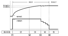
- FIG. The time chart of the display form of the battery voltage from the charge start in the charging device 1 to charge completion, charging current, and charge display LED9.
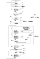
- 4 is a flowchart of control related to charging in the charging device 1.
- 4 is a flowchart of control related to USB output in the charging apparatus 1.
- FIG. 1 A of charging devices which concern on Embodiment 2 of this invention.
- FIG. 1 is a plan view of a charging apparatus 1 according to Embodiment 1 of the present invention.
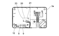
- FIG. 2 is a cross-sectional view taken along the line AA in FIG. 3 is a cross-sectional view taken along the line BB of FIG. 4 is a cross-sectional view taken along the line CC of FIG.
- FIG. 5 is a bottom view of the upper case 3 a of the charging device 1.
- the charging device 1 includes a case 3 in which an upper case 3a and a lower case 3b are combined.
- the upper case 3a and the lower case 3b are, for example, resin molded bodies.
- a decorative nameplate 16 is provided on the surface (upper surface) of the upper case 3a.
- the battery pack 13 is detachably mounted (slide mounted) on the battery pack mounting portion 3c.
- the charging device 1 is connected to an external power source such as a commercial power source by a power cord 19 and charges the attached battery pack 13 with power supplied from the external power source.
- a main board 4 having a charging function is provided (fixed) in the case 3.
- the main board 4 is mounted with a transformer 14, a coil 15, and other electronic components (described later in FIG. 6).
- the circuit on the main board 4 is divided into a primary side circuit (AC voltage side) and a secondary side circuit (charge control side) by the transformer 14, and is preferably insulated from each other.
- the upper case 3a is provided with a prism 5 as a light guide.
- the prism 5 is preferably plate-shaped and is integrally formed with the upper case 3a.
- An LED substrate 8 as a light emitting unit substrate is fixed to the lower end surface of the prism 5 with screws 12 as fixing members.
- the fixing of the LED substrate 8 to the prism 5 is not limited to screwing, and may be performed by other methods such as adhesion.
- the LED board 8 is equipped with a charge display LED 9 as a light emitting unit.
- the LED board 8 is provided separately from the main board 4. At least a part of the LED board 8 faces the portion of the main board 4 on which the primary circuit is mounted and is connected to the secondary circuit of the main board 4 by the lead wire 10. Has been.
- the lead wire 10 extends from the LED board 8 and is connected to a connector 11 provided on the main board 4, and has a role of supplying electric power necessary for driving the charging display LED 9 from the main board 4 to the LED board 8.
- the prism 5 extends from the charging display LED 9 side to the surface (upper surface) side of the upper case 3a, and has a role of guiding light emitted from the charging display LED 9 to the surface side of the upper case 3a.
- the prism 5 faces the outside (upper side) of the upper case 3a in the vicinity of the edge of the upper case 3a (preferably protrudes from the upper surface of the upper case 3a).
- the prism 5 protrudes outward from the surface of the upper case 3a, is disposed along the rear edge (inside the upper side in FIG. 1) of the case 3a, and extends in the left-right direction (left-right direction in the figure). It has an elongated shape.
- the portion of the prism 5 that faces the outside of the upper case 3a is preferably located at a position away from the battery pack 13 attached to the upper case 3a.
- the length L1 of the portion of the prism 5 facing the outside of the upper case 3a is preferably 1/3 or more of the length L2 of one side of the upper case 3a adjacent to the portion.
- the prism 5 has a light diffusion inclined surface (inclined portion) 6 facing the charging display LED 9 side.
- the light diffusion slope 6 is a triangular notch formed at the center of the lower edge of the prism 5.
- the light diffusion slope 6 has a role of widely diffusing the light emitted from the charging display LED 9 into the prism 5.
- the prism 5 has a slit 7 extending so as to cross between the charging display LED 9 and the upper case 3a.
- the slit 7 penetrates the prism 5 in the thickness direction, and has a role of irregularly reflecting light traveling in the prism 5.
- the charge display LED 9 is preferably a full-color LED, and includes three LEDs that respectively emit red, green, and blue light in one chip.
- a USB on / off switch (external power feeding changeover switch) 20 and a USB display LED (power feeding display unit) 21 are provided on the upper surface of the upper case 3 a. Further, a USB output terminal (external power feeding terminal) 22 is provided on the back surface of the case 3.
- the charging device 1 can supply direct-current power (for example, DC 5V) to an external electric device via the USB output terminal 22.
- the external power feeding terminal may be a terminal (connector) other than the USB output terminal.
- the USB on / off switch 20 is a momentary operation type (automatic return type) switch such as a tact switch. The user can switch between enabling and disabling the supply of DC power via the USB output terminal 22 by operating the USB on / off switch 20.
- the USB display LED 21 is turned on and off every time the user presses the USB on / off switch 20.
- the lighting and extinguishing of the USB display LED 21 correspond to validity and invalidity of the supply of DC power via the USB output terminal 22, respectively.
- the USB switch board (external power supply switching board) 23 on which the USB on / off switch 20 and the USB display LED 21 are mounted is provided separately from the main board 4, and at least a part thereof is the main board. 4 faces the part on which the primary circuit is mounted.
- FIG. 6 is a circuit block diagram of the charging apparatus 1.
- the charging device 1 converts AC power supplied from an AC power source 18 such as a commercial power source into DC power by an AC / DC converter 30, and charges the attached battery pack 13 and DC power via the USB output terminal 22. Supply.
- the charging device 1 supplies DC power from the battery pack 13 that is mounted to the USB output terminal 22. Details will be described below.
- the first rectifying / smoothing circuit 31 rectifies and smoothes the input voltage (for example, AC 100 V) from the AC power supply 18.
- the output voltage of the first rectifying / smoothing circuit 31 is applied to the primary winding of the transformer 14.
- the switching control circuit 33 performs switching control (for example, PWM control) on a switching element 34 such as FET or IGBT connected in series to the primary winding of the transformer 14. Thereby, an induced electromotive force is generated in the output winding (secondary winding and auxiliary winding) of the transformer 14.
- the three output voltages of the transformer 14 are input to the second rectifying / smoothing circuit 35, the third rectifying / smoothing circuit 36, and the fourth rectifying / smoothing circuit 37, and are rectified and smoothed.
- the switching control circuit 33 is activated by the activation current input from the output terminal of the first rectifying / smoothing circuit 31 via the activation resistor 32 and starts the switching control of the switching element 34 when connected to the AC power supply 18. Thereafter, the operation is performed by the supply voltage from the second rectifying / smoothing circuit 35.
- the output voltage of the third rectifying / smoothing circuit 36 is input to the positive terminal (C +) of the battery pack 13 via the relay 38 and also input to the DC / DC converter 39 via the diode D1.
- the output voltage of the battery pack 13 is also input to the DC / DC converter 39 via the power supply switch 41 and the diode D2.
- the output voltage of the DC / DC converter 39 is output from the USB output terminal 22 to the outside. That is, the third rectifying / smoothing circuit 36 is commonly used for supplying charging power to the battery pack 13 and supplying DC power via the USB output terminal 22.
- the battery pack 13 includes a plurality of secondary battery cells 13a such as rechargeable lithium batteries and a protection circuit 13b.
- the protection circuit 13b monitors the voltage and temperature of each secondary battery cell 13a. When the protection circuit 13b detects battery high temperature or overcharge, the protection circuit 13b notifies the microcomputer 50 as a control unit via the LS terminal. The protection circuit 13b also notifies the microcomputer 50 of the identification information of the battery pack 13 via the T terminal. When the overdischarge or overcurrent is detected, the protection circuit 13b notifies the microcomputer 50 via the LD terminal.
- the output voltage of the fourth rectifying / smoothing circuit 37 is stabilized by the constant voltage regulator 42 and supplied to the microcomputer 50. Further, the voltage at the positive terminal of the battery pack 13 is also input to the constant voltage regulator 42 via the power supply switch 41, stabilized by the constant voltage regulator 42, and supplied to the microcomputer 50.
- the microcomputer 50 performs overall operation control of the charging device 1. Control by the microcomputer 50 will be described later.
- the current (charging current) supplied from the third rectifying / smoothing circuit 36 to the secondary battery cell 13 a of the battery pack 13 is converted into a voltage by the current detection resistor 40 and input to the current feedback circuit 51.
- the current feedback circuit 51 transmits current feedback information to the power control signal feedback circuit 55 based on the terminal voltage of the current detection resistor 40 and the charging current setting information from the microcomputer 50.
- the voltage at the positive terminal of the battery pack 13 is detected by the first voltage detection circuit 52 and fed back to the microcomputer 50.
- the output voltage of the fourth rectifying / smoothing circuit 37 is detected by the second voltage detection circuit 53 and fed back to the microcomputer 50.
- the output voltages of the third rectifying / smoothing circuit 36 and the fourth rectifying / smoothing circuit 37 are detected by the voltage feedback circuit 54 and fed back to the power control signal feedback circuit 55.
- the voltage feedback circuit 54 switches between enabling and disabling the feedback of the output voltage of the third rectifying / smoothing circuit 36 and the fourth rectifying / smoothing circuit 37 according to the voltage feedback switching signal input from the microcomputer 50.
- the power supply control signal feedback circuit 55 transmits feedback information to the switching control circuit 33 in response to inputs from the current feedback circuit 51 and the voltage feedback circuit 54.
- the switching control circuit 33 performs switching control of the switching element 34 in accordance with feedback information from the power control signal feedback circuit 55.
- FIG. 7 is a display explanatory diagram of the charging display LED 9 according to the state of the charging device 1.
- FIG. 7 shows eight types of charge states, and the display colors (light emission colors) and display forms (light emission forms) of the charge display LEDs 9 corresponding thereto.
- the No. 1 standby state (pre-charging state) is a state in which the battery pack 13 is not attached to the charging device 1, the display color of the charging display LED 9 is red, and the display form is blinking.
- Each of No. 2 to No. 4 is in a charging state and is divided into three stages according to the progress of charging. No.
- the display color of the charging display LED 9 is light blue (green + blue), and the display form is blinking with a cycle longer than that of No. 1.
- No. 3 is in the state of being charged and the amount of charge is 50% to 80%, the display color of the charge display LED 9 is the same as No. 2, and the display form is the same period as No. 2 and the lighting time per time Is a long flashing.
- No. 4 is in a state of being charged and the amount of charge is 80% or more, the display color of the charge display LED 9 is the same as No. 2 and No. 3, and the display form is lit.
- No. 5 is a state where charging is completed, the display color of the charging display LED 9 is green, and the display form is lit.
- No. 6 is a high temperature standby state when the temperature of the battery pack 13 is higher than the threshold value, the display color of the charging display LED 9 is red, and the display form is blinking with a cycle earlier than No. 1.
- No. 7 is an error state due to an abnormality of the battery pack 13 or the charging device 1 (non-chargeable state), the display color of the charging display LED 9 is purple (red + blue), and the display form has a cycle earlier than that of No. 6. It is flashing.
- No. 8 is a state in which the charging device 1 is not connected to the AC power source 18, and the charging display LED 9 is turned off.
- FIG. 8 is a time chart of the battery voltage, the charging current, and the display form of the charging display LED 9 from the start of charging to the completion of charging in the charging device 1.
- the charging display LED 9 operates in the display form of No. 2 in FIG.
- the charge display LED 9 operates in the display form of No. 3 in FIG.
- the charge display LED 9 operates in the display form of No. 4 in FIG.
- the charging current is decreased stepwise.
- the charging display LED 9 operates in the display form of No. 5 in FIG.
- FIG. 9 is a flowchart of control related to charging in the charging apparatus 1.
- the charging device 1 is connected to the AC power source 18.
- the microcomputer 50 drives the charging display LED 9 in the display form No. 1 in FIG. 7 (S2).
- the microcomputer 50 confirms whether the battery pack 13 is abnormal (S4). If the battery pack 13 is normal (S4, YES), the microcomputer 50 checks the temperature of the battery pack 13 (S5).
- the microcomputer 50 starts charging the battery pack 13 (S6). Specifically, the microcomputer 50 turns on the relay 38 and applies the output voltage of the third rectifying / smoothing circuit 36 to the battery pack 13 (supplying a charging current from the third rectifying / smoothing circuit 36 to the battery pack 13). The microcomputer 50 continuously monitors the voltage of the battery pack 13 being charged. If the voltage of the battery pack 13 has not reached either of the predetermined voltages A and B (S7, NO, S8, NO), the microcomputer 50 drives the charge display LED 9 in the display form of No. 2 in FIG. S9).
- the microcomputer 50 drives the charge display LED 9 in the display form of No. 3 in FIG. 7 (S10).
- the microcomputer 50 drives the charge display LED 9 in the display form of No. 4 in FIG. 7 (S11).
- the microcomputer 50 stops charging (S13), and drives the charging display LED 9 in the display form No. 5 in FIG. 7 (S14).
- the microcomputer 50 When the battery pack 13 is removed from the charging device 1 (S15, YES), the microcomputer 50 returns to the pre-charging state shown in step S1.
- the microcomputer 50 detects an abnormality of the battery pack 13 in step S4 (S4, NO)
- the microcomputer 50 drives the charge display LED 9 in the display form of No. 7 in FIG. 7 (S16).
- the microcomputer 50 detects that the battery pack 13 is in a high temperature state equal to or higher than the predetermined temperature in step S5 (S5, YES)
- the microcomputer 50 drives the charge display LED 9 in the display form No. 6 in FIG. 7 (S17).
- FIG. 10 is a flowchart of control related to USB output in the charging apparatus 1.
- the control shown in this flowchart is performed in parallel with the charging control (main control) shown in FIG.
- the microcomputer 50 switches between the USB on mode and the USB off mode.
- the USB on mode corresponds to the validity of the DC power supply from the USB output terminal 22, and the USB off mode corresponds to the invalidity of the DC power supply.
- the microcomputer 50 switches from the USB off mode to the USB on mode (S23, YES)
- the microcomputer 50 turns on the power supply switch 41 and holds the power supply from the plus terminal of the battery pack 13 to the microcomputer 50 (S24).
- the microcomputer 50 confirms whether or not an AC voltage is input from the AC power source 18 (S25). If there is an AC voltage input (S25, YES), the display mode of the charging display LED 9 is charged according to the main control shown in FIG. While changing according to the state (S26), the USB display LED 21 is turned on (S27).
- the microcomputer 50 If the battery pack 13 is connected to the charging device 1 (S28, YES), and the identification result of the battery pack 13 is normal (S29, YES), the microcomputer 50 is not fully charged ( (S30, NO), it is confirmed whether or not the battery pack 13 is being charged (S31). If the battery pack 13 is being charged (S31, YES), the microcomputer 50 displays the charging display LED 9 during charging (S32), and checks whether the voltage of the battery pack 13 is equal to or higher than a predetermined value (S33). If the battery pack 13 is not being charged in step S31 (S31, NO), the microcomputer 50 skips step S32 and confirms whether the voltage of the battery pack 13 is equal to or higher than a predetermined value (S33).
- the microcomputer 50 sets the DC / DC converter 39 in the driving state and enables the DC power supply from the USB output terminal 22 (S34).
- the microcomputer 50 stops the DC / DC converter 39 and invalidates the DC power supply from the USB output terminal 22. (S35).
- the microcomputer 50 switches the DC / DC converter 39 from the stop state to the drive state, and validates the DC power supply from the USB output terminal 22.
- step S30 If the charging of the battery pack 13 has been completed in step S30 (S30, YES), the microcomputer 50 sets the charging display LED 9 to the charging completion display (S36), sets the DC / DC converter 39 in the driving state, and outputs the USB.
- the DC power supply from the terminal 22 is validated (S37). If the identification result of the battery pack 13 is not normal in step S29 (S29, NO), the microcomputer 50 displays the charge display LED 9 as an error (S38), stops the DC / DC converter 39, and outputs the USB output terminal.
- the DC power supply from 22 is invalidated (S39).
- step S28 the microcomputer 50 sets the charge display LED 9 to the standby display (S40), sets the DC / DC converter 39 to the drive state, and turns the USB The DC power supply from the output terminal 22 is validated (S41).
- step S25 If there is no input of the AC voltage from the AC power source 18 in step S25 (S25, NO), the microcomputer 50 turns off the charging display LED 9 (S42), and the identification result of the battery pack 13 is normal (S43, YES). If the voltage of the battery pack 13 is equal to or higher than the predetermined value (S44, YES), the USB display LED 21 is turned on (S45), and the DC / DC converter 39 is driven to supply DC power from the USB output terminal 22. Enable (S46). On the other hand, if the identification result of the battery pack 13 is not normal in step S43 (S43, NO) and if the voltage of the battery pack 13 does not reach a predetermined value in step S44 (S44, NO), the microcomputer 50 displays the USB.
- the LED 21 is turned off (S47), the DC / DC converter 39 is stopped, the DC power supply from the USB output terminal 22 is disabled (S48), the power supply switch 41 is turned off, and the microcomputer 50 from the battery pack 13 is turned off. The power supply to is canceled (S49). As a result, the microcomputer 50 stops.
- step S23 When the microcomputer 50 switches from the USB on mode to the USB off mode in step S23 (S23, NO), the USB display LED 21 is turned off (S50), the DC / DC converter 39 is stopped, and the USB output terminal 22 is turned off.
- the DC power supply from is invalidated (S51), and the power supply switch 41 is turned off to release the power supply from the battery pack 13 to the microcomputer 50 (S52). Thereafter, if the connection with the AC power supply 18 is valid, the microcomputer 50 continues to be turned on by the power supplied from the AC power supply 18.
- FIG. 11 is a combination table of each state and operation mode in the charging apparatus 1.
- Each state shown in FIG. 11 is based on the case where the USB on / off switch 20 is operated and the DC power supply from the USB output terminal 22 is validated.
- No. 1 is a normal standby state, the AC power supply 18 is connected, the battery pack 13 is not connected, the DC power supply from the USB output terminal 22 is valid, and the charging display LED 9 is displayed in the display mode 1 (standby) shown in FIG. Display), the USB display LED 21 is lit.
- No. 1 is a normal standby state
- the AC power supply 18 is connected
- the battery pack 13 is not connected
- the DC power supply from the USB output terminal 22 is valid
- the charging display LED 9 is displayed in the display mode 1 (standby) shown in FIG. Display)
- the USB display LED 21 is lit.
- the charging display LED 9 is displayed in the display mode 6 ( The high temperature standby display) and the USB display LED 21 are lit.
- No. 3 is an identification error state of the battery pack 13, the AC power supply 18 is connected, the battery pack 13 is connected, and the DC power supply from the USB output terminal 22 is invalid (however, after the identification error is resolved) (Automatic return), the charging display LED 9 is in the display form 7 (error display) shown in FIG. 7, and the USB display LED 21 is lit.
- No. 4 is an overdischarge state of the battery pack 13, the AC power supply 18 is connected, the battery pack 13 is connected, and the DC power supply from the USB output terminal 22 is invalid (however, after the overdischarge is eliminated) Auto-recovery), the charging display LED 9 is in the display mode 2 shown in FIG. 7 (displaying charging and less than 50% charge), and the USB display LED 21 is lit. In No. 3 and No. 4, the DC power supply from the USB output terminal 22 is invalid, but the USB display LED 21 is lit.
- No. 5 indicates that the battery pack 13 is not being overdischarged and is in a fully charged state, the AC power supply 18 is connected, the battery pack 13 is connected, the DC power supply from the USB output terminal 22 is valid, and the charging indicator LED 9 Is one of the display modes 2 to 5 shown in FIG. 7 (charging or charging completion display), and the USB display LED 21 is lit.
- the process proceeds to No. 6 described later.
- No. 6 is that the AC power supply 18 is not connected, the battery pack 13 is connected, the DC power supply from the USB output terminal 22 is valid, the charging display LED 9 is off, the USB display LED 21 is on, and the power of the battery pack 13 is In this state, DC power is supplied to the USB output terminal 22.
- No. 7 is no AC power supply 18 connected, battery pack 13 is connected, battery pack 13 is in an overdischarged state, DC power supply from USB output terminal 22 is disabled, charging display LED 9 is turned off, and USB display LED 21 is turned off. In this state, DC power is not supplied to the USB output terminal 22.
- the charging apparatus 1 is connected to the AC power source 18, the process proceeds to No. 4.
- the eaves prism 5 faces the outer side (upper side) of the upper case 3a in the vicinity of the edge of the upper case 3a, the prism 5 faces the outer side of the upper case 3a at the center of the upper case 3a as in a comparative example described later.
- the range in which the prism 5 is hidden behind the battery pack 13 can be reduced, and the visibility of the prism 5 and thus the visibility of the light emitted from the charge display LED 9 led to the prism 5 is improved. .
- the prism 5 Since the portion of the eaves prism 5 facing the outside of the upper case 3a is located at a position away from the battery pack 13 attached to the upper case 3a as compared with the same portion in a comparative example described later, the prism 5 is a battery. The range hidden behind the pack 13 can be reduced, and the visibility of the prism 5 and thus the visibility of the light emitted from the charge display LED 9 led to the prism 5 are improved.
- the LED board 8 Since the LED board 8 is provided separately from the main board 4, the degree of freedom of arrangement of the charging display LED 9 is increased. For this reason, for example, the charge display LED 9 can be disposed under a position with good visibility on the surface of the upper case 3a, such as on the portion of the main board 4 where the primary circuit is mounted, and the charge display LED 9 emits light. The visibility of light can be improved. In addition, the dead space in the case 3 can be effectively used, and the prism 5 can be enlarged, and the visibility of the light emitted from the charge display LED 9 can be improved. Further, since the main board 4 does not need to have the function of the LED board 8, the main board 4 can be efficiently wired, which is advantageous for downsizing the main board 4.
- the eaves prism 5 has a plate shape extending from the charge display LED 9 side to the surface side of the upper case 3a and has the light diffusion slope 6 facing the charge display LED 9 side, the light emitted from the charge display LED 9 is diffused over a wide range. The visibility of the light emitted from the charging display LED 9 is improved.
- the eaves prism 5 Since the eaves prism 5 has the slit 7 extending so as to cross between the charging display LED 9 and the upper case 3a, the light of the charging display LED 9 traveling in the prism 5 is irregularly reflected by the slit 7, and the charging display LED 9 The emitted light is diffused in a wide range, and the visibility of the light emitted from the charge display LED 9 is improved.
- the charging display LED 9 includes a blue LED, it is possible to display a color that could not be displayed conventionally as a charging device for charging a battery pack for an electric tool.
- the charging display LED 9 is a full-color LED, it can emit various kinds of colors as compared with the conventional case. For this reason, the common charge display LED 9 and the prism 5 display a plurality of stages of charging progress and charging states other than the charging progress (pre-charging state, charging completion state, battery high temperature standby state, unchargeable state, etc.). It becomes possible.
- the USB on / off switch 20 can be switched between valid / invalid of DC power supply via the USB output terminal 22, so that it is easy to use.
- USB switch board 23 on which the USB on / off switch 20 and the USB display LED 21 are mounted is provided separately from the main board 4, the degree of freedom of arrangement of the USB on / off switch 20 and the USB display LED 21 is high. .
- USB display LED 21 is provided separately from the charge display LED 9, the display related to independent functions is separated from each other, so that it is easy for the user to understand.
- the third rectifying / smoothing circuit 36 is shared for supplying charging power to the battery pack 13 and supplying DC power via the USB output terminal 22, an increase in the number of circuit components can be suppressed.
- the microcomputer 50 disables the supply of DC power via the USB output terminal 22, so that the DC / DC converter 39 is prevented from malfunctioning due to the low input voltage from the battery pack 13.
- FIG. 12 is a plan view of a charging device 1A according to Embodiment 2 of the present invention.
- 13 is a cross-sectional view taken along the line DD of FIG. 14 is a cross-sectional view taken along line EE in FIG.
- prism 5 is arranged along an edge of upper case 3a different from that of the first embodiment. That is, the prism 5 has an elongated shape along the front-rear direction of the upper case 3a (vertical direction in FIG. 12), and is disposed along the left edge of the upper case 3a.
- Other points of the present embodiment are the same as those of the first embodiment.
- the present embodiment can achieve the same effects as those of the first embodiment.
- FIG. 15 is a plan view of a charging device 1B according to a comparative example.
- 16 is a cross-sectional view taken along the line FF in FIG. 17 is a cross-sectional view taken along the line GG in FIG.
- the charging device 1B of this comparative example has two charging display LEDs 9, each provided in a secondary circuit on the main board 4, and the prism 5 is cylindrical. Each charging display LED 9 extends upward.
- the prism 5 extending upward from the charging display LED 9 side is It faces the outside of the upper case 3a just beside the battery pack 13, and is often hidden behind the battery pack 13 and has poor visibility.
- such a visibility problem can be preferably solved.
- the prism 5 may be arranged along the lower edge of FIG. Although the prism 5 has been described as an elongated shape, the shape is not limited as long as it is a shape that protrudes outward from the upper surface of the case 3 (upper case 3a) and extends along the upper surface, such as a circular shape or a square shape. .
- SYMBOLS 1 Charging device, 3 ... Case, 3a ... Upper case (upper outer frame), 3b ... Lower case (lower outer frame), 4 ... Main board, 5 ... Prism (light guide), 6 ... Light diffusion slope (inclination) Part), 7 ... slit, 8 ... LED substrate (light emitting part substrate), 9 ... charge indicator LED (light emitting part), 10 ... lead wire, 11 ... connector, 12 ... screw (fixing member), 13 ... battery pack, 13a ... secondary battery cell, 13b ... protection circuit, 14 ... transformer, 15 ... coil, 16 ... decoration nameplate, 18 ... alternating current power supply, 19 ... power cord, 20 ...
- USB on / off switch (external power supply switch), 21 ... USB display LED (display unit for power supply), 22 ... USB output terminal (external power supply terminal), 23 ... USB switch board (external power supply switching board), 30 ... AC / DC converter, 31 ... first rectifying and smoothing circuit, 32 ... Starting resistance, 3 DESCRIPTION OF SYMBOLS ... Switching control circuit, 34 ... Switching element, 35 ... 2nd rectification smoothing circuit, 36 ... 3rd rectification smoothing circuit, 37 ... 4th rectification smoothing circuit, 38 ... Relay, 39 ... DC / DC converter, 40 ... Current detection resistance , 41 ... power supply switch, 42 ... constant voltage regulator, 50 ... control unit, 51 ... current feedback circuit, 52 ... first voltage detection circuit, 53 ... second voltage detection circuit, 54 ... voltage feedback circuit, 55 ... power supply control Signal feedback circuit
Landscapes
- Engineering & Computer Science (AREA)
- Manufacturing & Machinery (AREA)
- Chemical & Material Sciences (AREA)
- Chemical Kinetics & Catalysis (AREA)
- Electrochemistry (AREA)
- General Chemical & Material Sciences (AREA)
- Power Engineering (AREA)
- Charge And Discharge Circuits For Batteries Or The Like (AREA)
Abstract
従来と比較して発光部の発する光の視認性が良好な充電装置を提供するため、充電装置1は、電池パック13を着脱可能に装着するケース3と、ケース3内に設けられた充電表示LEDと、充電表示LEDの発した光をケース3の表面側に導くプリズム5と、を備え、プリズム5は、上ケース3aの表面から外側に突出しており、上ケース3aの後側の縁に沿って配置されており、左右方向に伸びた細長い形状である。プリズム5の、ケース3の外側に臨む部分の長さL1が、当該部分と近接するケース3の1辺の長さL2の1/3以上である。
Description
本発明は、例えばコードレス電動工具に着脱可能に装着される電池パックを充電する充電装置に関する。
コードレス電動工具は、駆動源であるモータに電力を供給するための電池パックを着脱自在に装着する。電池パックは、充電可能なリチウム電池等の二次電池セルを内蔵する。電池パックの充電には充電装置が用いられる。充電装置は、充電状態を表示するLED等の発光部を備える。発光部は、充電装置の二次側回路からの電力供給により点灯する。発光部の発する光は、プリズム等の導光体により、ケースの上面に導かれる。
従来の充電装置では、発光部の発する光は柱状の導光体によりケースの上面中央に導かれていたが、ケースの上面中央は、充電装置に装着した電池パックのすぐ傍となる位置であるため、発光部の発する光が電池パックに隠れて見えないことが多かった。また、従来の充電装置では、発光部の光の色が赤と緑しかなく、赤と緑あるいはそれらを組み合わせた色しか表せなかった。また、従来の充電装置は、電池パックに対する充電機能しか持たず、利便性の点で改善の余地があった。
本発明はこうした状況を認識してなされたものであり、その第1の目的は、従来と比較して発光部の発する光の視認性が良好な充電装置を提供することにある。
本発明の第2の目的は、電動工具用の電池パックを充電する充電装置において、従来は表示することができなかった色を表示可能な充電装置を提供することにある。
本発明の第3の目的は、電池パックに対する充電機能以外の機能を有する利便性の高い充電装置を提供することにある。
本発明は、充電装置である。この充電装置は、上表面を有し電池パックを着脱可能に装着するケースと、前記ケース内に設けられた発光部と、前記発光部の発した光を前記ケースの表面側に導く導光体と、を備え、前記導光体は、前記上表面から外側に突出し、前記上表面に沿って伸びる。
本発明は、充電装置である。この充電装置は、電池パックを着脱可能に装着するケースと、前記ケース内に設けられた発光部と、前記発光部の発した光を前記ケースの表面側に導く導光体と、を備え、前記導光体の、前記ケースの外側に臨む部分が、前記ケースに装着した電池パックから離間する位置にある。
前記導光体の、前記ケースの外側に臨む部分の長さが、当該部分と近接する前記ケースの1辺の長さの1/3以上であってもよい。
前記ケース内において、前記発光部を搭載した発光部基板が、充電機能を有するメイン基板とは別に設けられていてもよい。
前記発光部基板が、前記導光体に固定されていてもよい。
前記発光部基板の少なくとも一部が、前記メイン基板のうち一次側回路を搭載した部分と対面する位置にあってもよい。
前記発光部基板が、前記メイン基板の二次側回路とリード線によって接続されていてもよい。
前記導光体は、前記発光部側から前記ケースの表面側に延びる板状であり、前記発光部側に臨む光拡散用の傾斜部を有してもよい。
前記導光体が、前記発光部と前記ケースの表面との間を横切るように延びるスリットを有してもよい。
前記導光体が、前記ケースと一体成形されていてもよい。
前記発光部が青色LEDを含んでもよい。
本発明は、充電装置である。この充電装置は、電池パックを着脱可能に装着するケースと、前記ケース内に設けられた発光部と、前記発光部の発した光を前記ケースの表面側に導く導光体と、を備え、前記導光体は、前記発光部側から前記ケースの表面側に延びる板状であり、前記導光体は、前記発光部と前記ケースの表面との間を横切るように延びるスリットと、前記発光部側に臨む光拡散用の傾斜部と、の少なくとも一方を有する。
本発明は、電動工具用の電池パックを充電する充電装置であって、電池パックを着脱可能に装着するケースと、前記ケース内に設けられた、青色LEDを含む発光部と、を備える。
前記発光部が、赤色LED及び緑色LEDを含んでもよい。
前記発光部の発した光を前記ケースの表面側に導く導光体を備え、共通の前記発光部及び前記導光体により、複数段階の充電進行状況、及び充電進行状況以外の充電状態を表示してもよい。
外部の電気機器に直流電力を供給可能な外部給電用端子と、前記外部給電用端子を経由した直流電力の供給に関する給電用表示部と、を備える。
前記外部給電用端子を経由した直流電力の供給の有効、無効を切り替えるための外部給電切替スイッチを有してもよい。
前記外部給電切替スイッチ及び前記給電用表示部を搭載した外部給電切替用基板が、充電機能を有するメイン基板とは別に設けられていてもよい。
前記外部給電用端子を経由した直流電力の供給に関する給電用表示部と、装着した電池パックの充電に関する充電用表示部と、を別々に備えてもよい。
なお、以上の構成要素の任意の組合せ、本発明の表現を方法やシステムなどの間で変換したものもまた、本発明の態様として有効である。
本発明によれば、従来と比較して発光部の発する光の視認性が良好な充電装置を提供することができる。
本発明によれば、電動工具用の電池パックを充電する充電装置において、従来は表示することができなかった色を表示可能な充電装置を提供することができる。
本発明によれば、電池パックに対する充電機能以外の機能を有する利便性の高い充電装置を提供することができる。
以下、図面を参照しながら本発明の好適な実施の形態を詳述する。なお、各図面に示される同一または同等の構成要素、部材、処理等には同一の符号を付し、適宜重複した説明は省略する。また、実施の形態は発明を限定するものではなく例示であり、実施の形態に記述されるすべての特徴やその組み合わせは必ずしも発明の本質的なものであるとは限らない。
実施の形態1 図1は、本発明の実施の形態1に係る充電装置1の平面図である。図2は、図1のA-A断面図である。図3は、図1のB-B断面図である。図4は、図1のC-C断面図である。図5は、充電装置1の上ケース3aの底面図である。充電装置1は、上ケース3a及び下ケース3bを組み合わせたケース3を備える。上ケース3a及び下ケース3bは、例えば樹脂成形体である。上ケース3aの表面(上面)には、飾り銘板16が設けられる。上ケース3aは、電池パック装着部3cに電池パック13を着脱可能に装着(スライド装着)する。充電装置1は、電源コード19により商用電源等の外部電源に接続され、当該外部電源からの供給電力により、装着した電池パック13を充電する。
図2に示すように、ケース3内には、充電機能を有するメイン基板4が設けられる(固定される)。メイン基板4は、トランス14及びコイル15並びにその他の電子部品(図6で後述)を搭載している。メイン基板4上の回路は、トランス14により一次側回路(AC電圧側)と二次側回路(充電制御側)に分かれており、好ましくは相互に絶縁されている。
上ケース3aには、導光体としてのプリズム5が設けられる。プリズム5は、好ましくは板状であって上ケース3aと一体成形される。プリズム5の下端面には、発光部基板としてのLED基板8が、固定部材としてのネジ12により固定される。なお、プリズム5に対するLED基板8の固定は、ネジ止めに限定されず、接着等の他の方法によってもよい。LED基板8は、発光部としての充電表示LED9を搭載している。LED基板8は、メイン基板4とは別に設けられており、少なくとも一部がメイン基板4のうち一次側回路を搭載した部分と対面し、メイン基板4の二次側回路とリード線10によって接続されている。リード線10は、LED基板8から延びてメイン基板4に設けられたコネクタ11に接続され、メイン基板4からLED基板8に、充電表示LED9の駆動に必要な電力を供給する役割を持つ。プリズム5は、充電表示LED9側から上ケース3aの表面(上面)側に延びており、充電表示LED9の発した光を上ケース3aの表面側に導く役割を持つ。プリズム5は、上ケース3aの縁の近傍において上ケース3aの外側(上側)に臨む(好ましくは上ケース3aの上表面から突出する)。すなわち、プリズム5は上ケース3aの表面から外側に突出しており、ケース3aの後側の縁(図1の上側の内)に沿って配置されており、左右方向(図の左右方向)に伸びた細長い形状である。プリズム5の、上ケース3aの外側に臨む部分は、好ましくは上ケース3aに装着した電池パック13から離間する位置にある。図1に示すように、プリズム5の、上ケース3aの外側に臨む部分の長さL1は、当該部分と近接する上ケース3aの1辺の長さL2の好ましくは1/3以上である。プリズム5は、充電表示LED9側に臨む光拡散斜面(傾斜部)6を有する。光拡散斜面6は、図示の例ではプリズム5の下縁中央部に形成された三角形状の切欠部である。光拡散斜面6は、充電表示LED9の発した光を、プリズム5内に広く拡散させる役割を持つ。プリズム5は、充電表示LED9と上ケース3aとの間を横切るように延びるスリット7を有する。スリット7は、プリズム5を厚み方向に貫通しており、プリズム5内を進む光を乱反射させる役割を持つ。充電表示LED9は、好ましくは、フルカラーLEDであり、1つのチップ内に赤色、緑色、青色にそれぞれ発光する3つのLEDを含む。
図1に示すように、上ケース3aの上面には、USBオン/オフスイッチ(外部給電切替スイッチ)20及びUSB表示LED(給電用表示部)21が設けられる。また、ケース3の背面には、USB出力端子(外部給電用端子)22が設けられる。充電装置1は、USB出力端子22を経由して、外部の電気機器に直流電力(例えばDC5V)を供給可能である。なお、外部給電用端子はUSB出力端子以外の端子(コネクタ)であってもよい。USBオン/オフスイッチ20は、例えばタクトスイッチ等のモーメンタリ動作型(自動復帰型)のスイッチである。使用者は、USBオン/オフスイッチ20の操作により、USB出力端子22を経由した直流電力の供給の有効、無効を切り替えることができる。USB表示LED21は、使用者がUSBオン/オフスイッチ20を押す度に点灯、消灯が切り替わる。USB表示LED21の点灯、消灯は、USB出力端子22を経由した直流電力の供給の有効、無効にそれぞれ対応する。図5に示すように、USBオン/オフスイッチ20及びUSB表示LED21を搭載したUSBスイッチ基板(外部給電切替用基板)23は、メイン基板4とは別に設けられており、少なくとも一部がメイン基板4のうち一次側回路を搭載した部分と対面する。
図6は、充電装置1の回路ブロック図である。充電装置1は、商用電源等の交流電源18からの供給された交流電力をAC/DCコンバータ30により直流電力に変換し、装着した電池パック13の充電、及びUSB出力端子22を経由した直流電力の供給を行う。また、充電装置1は、交流電源18との接続が断たれると、装着した電池パック13からUSB出力端子22に直流電力を供給する。以下、詳細に説明する。
充電装置1において、第1整流平滑回路31は、交流電源18からの入力電圧(例えばAC100V)を整流、平滑する。第1整流平滑回路31の出力電圧は、トランス14の一次巻線に印加される。スイッチング制御回路33は、トランス14の一次巻線に直列接続されたFETやIGBT等のスイッチング素子34をスイッチング制御(例えばPWM制御)する。これにより、トランス14の出力巻線(二次巻線及び補助巻線)に誘導起電力が発生する。トランス14の3系統の出力電圧は、第2整流平滑回路35、第3整流平滑回路36、及び第4整流平滑回路37にそれぞれ入力され、整流、平滑される。なお、スイッチング制御回路33は、交流電源18への接続時、第1整流平滑回路31の出力端子から起動抵抗32を経由して入力される起動電流により起動してスイッチング素子34のスイッチング制御を開始し、その後は第2整流平滑回路35からの供給電圧により動作する。
第3整流平滑回路36の出力電圧は、リレー38を介して電池パック13のプラス端子(C+)に入力されると共に、ダイオードD1を介してDC/DCコンバータ39に入力される。また、電池パック13の出力電圧も、電力供給スイッチ41及びダイオードD2を介してDC/DCコンバータ39に入力される。DC/DCコンバータ39の出力電圧は、USB出力端子22から外部に出力される。すなわち、第3整流平滑回路36は、電池パック13への充電用電力の供給、及びUSB出力端子22を経由した直流電力の供給に共用される。
電池パック13は、充電可能なリチウム電池等の複数の二次電池セル13a、及び保護回路13bを内蔵する。保護回路13bは、各二次電池セル13aの電圧、温度を監視する。保護回路13bは、電池高温あるいは過充電を検出すると、LS端子を経由して制御部としてのマイコン50に報知する。保護回路13bは、また、電池パック13の識別情報を、T端子を経由してマイコン50に報知する。保護回路13bは、また、過放電や過電流を検出すると、LD端子を経由してマイコン50に報知する。
第4整流平滑回路37の出力電圧は、定電圧レギュレータ42によって安定化され、マイコン50に供給される。また、電力供給スイッチ41を経由して、電池パック13のプラス端子の電圧も、定電圧レギュレータ42に入力され、定電圧レギュレータ42によって安定化され、マイコン50に供給される。マイコン50は、充電装置1の全体的な動作制御を行う。マイコン50による制御については後述する。第3整流平滑回路36から電池パック13の二次電池セル13aに供給される電流(充電電流)は、電流検出抵抗40によって電圧に変換され、電流フィードバック回路51に入力される。電流フィードバック回路51は、電流検出抵抗40の端子電圧及びマイコン50からの充電電流設定情報に基づいて、電源制御信号フィードバック回路55に電流フィードバック情報を送信する。電池パック13のプラス端子の電圧は、第1電圧検出回路52によって検出され、マイコン50にフィードバックされる。第4整流平滑回路37の出力電圧は、第2電圧検出回路53によって検出され、マイコン50にフィードバックされる。第3整流平滑回路36及び第4整流平滑回路37の出力電圧は、電圧フィードバック回路54によって検出され、電源制御信号フィードバック回路55にフィードバックされる。電圧フィードバック回路54は、マイコン50から入力される電圧フィードバック切替信号に応じて、第3整流平滑回路36及び第4整流平滑回路37の出力電圧のフィードバックの有効、無効を切り替える。電源制御信号フィードバック回路55は、電流フィードバック回路51及び電圧フィードバック回路54からの入力に応じて、スイッチング制御回路33にフィードバック情報を送信する。スイッチング制御回路33は、電源制御信号フィードバック回路55からのフィードバック情報に応じて、スイッチング素子34のスイッチング制御を行う。
図7は、充電装置1の状態に応じた充電表示LED9の表示説明図である。図7では、8種類の充電状態、並びにそれに応じた充電表示LED9の表示色(発光色)及び表示形態(発光形態)を示している。No.1の待機状態(充電前状態)は、充電装置1に電池パック13が装着されていない状態であり、充電表示LED9の表示色は赤色で、表示形態は点滅である。No.2~No.4は、共に充電中状態であり、充電の進行状況に応じて3段階に分かれている。No.2は、充電中かつ充電量50%未満の状態であり、充電表示LED9の表示色は水色(緑+青)で、表示形態はNo.1よりも周期の長い点滅である。No.3は、充電中かつ充電量50%~80%の状態であり、充電表示LED9の表示色はNo.2と同じで、表示形態はNo.2と同周期で1回あたりの点灯時間が長い点滅である。No.4は、充電中かつ充電量80%以上の状態であり、充電表示LED9の表示色はNo.2及びNo.3と同じで、表示形態は点灯である。No.5は、充電完了状態であり、充電表示LED9の表示色は緑色で、表示形態は点灯である。No.6は、電池パック13の温度が閾値より高い場合の高温待機状態であり、充電表示LED9の表示色は赤色で、表示形態はNo.1より早い周期の点滅である。No.7は、電池パック13又は充電装置1の異常によるエラー状態(充電不可状態)であり、充電表示LED9の表示色は紫色(赤+青)で、表示形態はNo.6より早い周期の点滅である。No.8は、充電装置1が交流電源18に接続されていない状態であり、充電表示LED9は消灯である。
図8は、充電装置1における充電開始から充電完了までの電池電圧、充電電流、及び充電表示LED9の表示形態のタイムチャートである。時刻t1において充電が開始されると、充電電流が立ち上がると共に、電池パック13の電圧が充電の進行により上昇する。また、充電表示LED9は図7のNo.2の表示形態で動作する。充電が進み、時刻t2において電池パック13の電圧が所定電圧B(充電量50%に対応)になると、充電表示LED9は図7のNo.3の表示形態で動作する。さらに充電が進み、時刻t3において電池パック13の電圧が所定電圧A(充電量80%に対応)になると、充電表示LED9は図7のNo.4の表示形態で動作する。また、時刻t3以降、充電電流は段階的に低下させる。そして時刻t4において充電が完了すると、充電表示LED9は図7のNo.5の表示形態で動作し、充電電流は0になる。
図9は、充電装置1における充電に関する制御のフローチャートである。このフローチャートの前提として、充電装置1は交流電源18に接続されているものとする。マイコン50は、充電装置1に電池パック13が装着されていない充電前状態では(S1)、充電表示LED9を図7のNo.1の表示形態で駆動する(S2)。マイコン50は、充電装置1に電池パック13が装着されると(S3,YES)、電池パック13の異常有無を確認する(S4)。マイコン50は、電池パック13が正常であれば(S4,YES)、電池パック13の温度を確認する(S5)。マイコン50は、電池パック13が所定温度以上の高温状態でなければ(S5,NO)、電池パック13の充電を開始する(S6)。具体的には、マイコン50は、リレー38をオンにし、第3整流平滑回路36の出力電圧を電池パック13に印加する(第3整流平滑回路36から電池パック13に充電電流を供給する)。マイコン50は、充電中の電池パック13の電圧を継続的に監視する。マイコン50は、電池パック13の電圧が所定電圧A,Bのいずれにも達していなければ(S7,NO、S8,NO)、充電表示LED9を図7のNo.2の表示形態で駆動する(S9)。マイコン50は、電池パック13の電圧が所定電圧A未満かつ所定電圧B以上になると(S7,NO、S8,YES)、充電表示LED9を図7のNo.3の表示形態で駆動する(S10)。マイコン50は、電池パック13の電圧が所定電圧A以上になると(S7,YES)、充電表示LED9を図7のNo.4の表示形態で駆動する(S11)。マイコン50は、充電完了条件が満たされると(S12,YES)、充電を停止し(S13)、充電表示LED9を図7のNo.5の表示形態で駆動する(S14)。マイコン50は、電池パック13が充電装置1から外されると(S15,YES)、ステップS1に示す充電前状態に戻る。マイコン50は、ステップS4において電池パック13の異常を検出すると(S4,NO)、充電表示LED9を図7のNo.7の表示形態で駆動する(S16)。マイコン50は、ステップS5において電池パック13が所定温度以上の高温状態であることを検出すると(S5,YES)、充電表示LED9を図7のNo.6の表示形態で駆動する(S17)。
図10は、充電装置1におけるUSB出力に関する制御のフローチャートである。このフローチャートに示す制御は、図9に示す充電制御(メイン制御)と並行して行われる。マイコン50は、USBオン/オフスイッチ20が押されると(S21,YES)、USBオンモード及びUSBオフモードの間での切替えを行う。USBオンモードは、USB出力端子22からの直流電力供給の有効に対応し、USBオフモードは、同直流電力供給の無効に対応する。マイコン50は、USBオフモードからUSBオンモードに切り替えた場合(S23,YES)、電力供給スイッチ41をオンにし、電池パック13のプラス端子からマイコン50への電力供給を保持する(S24)。マイコン50は、交流電源18からの交流電圧の入力有無を確認し(S25)、交流電圧の入力があれば(S25,YES)、図9に示すメイン制御に従い、充電表示LED9の表示形態を充電状態に応じて変化させる(S26)と共に、USB表示LED21をオンにする(S27)。
マイコン50は、充電装置1に電池パック13が接続されていて(S28,YES)、電池パック13の識別結果が正常であり(S29,YES)、電池パック13の充電が未完了であれば(S30,NO)、電池パック13が充電中かどうかを確認する(S31)。マイコン50は、電池パック13が充電中であれば(S31,YES)、充電表示LED9を充電中表示にし(S32)、電池パック13の電圧が所定値以上か否かを確認する(S33)。なお、マイコン50は、ステップS31において電池パック13が充電中でなければ(S31,NO)、ステップS32を飛ばして電池パック13の電圧が所定値以上か否かを確認する(S33)。マイコン50は、電池パック13の電圧が所定値以上であれば(S33,YES)、DC/DCコンバータ39を駆動状態とし、USB出力端子22からの直流電力供給を有効にする(S34)。一方、マイコン50は、ステップS33において電池パック13の電圧が所定値に満たない場合は(S33,NO)、DC/DCコンバータ39を停止状態とし、USB出力端子22からの直流電力供給を無効にする(S35)。マイコン50は、電池パック13の電圧が所定値未満から所定値以上に回復したら、DC/DCコンバータ39を停止状態から駆動状態に切り替え、USB出力端子22からの直流電力供給を有効化する。
マイコン50は、ステップS30において電池パック13の充電が完了していた場合(S30,YES)、充電表示LED9を充電完了表示にする(S36)と共に、DC/DCコンバータ39を駆動状態とし、USB出力端子22からの直流電力供給を有効にする(S37)。マイコン50は、ステップS29において電池パック13の識別結果が正常でなければ(S29,NO)、充電表示LED9をエラー表示にする(S38)と共に、DC/DCコンバータ39を停止状態とし、USB出力端子22からの直流電力供給を無効にする(S39)。マイコン50は、ステップS28において充電装置1に電池パック13が接続されていなければ(S28,NO)、充電表示LED9を待機表示にする(S40)と共に、DC/DCコンバータ39を駆動状態とし、USB出力端子22からの直流電力供給を有効にする(S41)。
マイコン50は、ステップS25において交流電源18からの交流電圧の入力が無ければ(S25,NO)、充電表示LED9を消灯し(S42)、電池パック13の識別結果が正常であり(S43,YES)、電池パック13の電圧が所定値以上であれば(S44,YES)、USB表示LED21を点灯する(S45)と共に、DC/DCコンバータ39を駆動状態とし、USB出力端子22からの直流電力供給を有効にする(S46)。一方、マイコン50は、ステップS43において電池パック13の識別結果が正常でない場合(S43,NO)、及びステップS44において電池パック13の電圧が所定値に満たない場合(S44,NO)は、USB表示LED21を消灯する(S47)と共に、DC/DCコンバータ39を停止状態とし、USB出力端子22からの直流電力供給を無効にし(S48)、さらに電力供給スイッチ41をオフにして電池パック13からマイコン50への電力供給を解除する(S49)。これによりマイコン50は停止する。
マイコン50は、ステップS23において、USBオンモードからUSBオフモードに切り替えた場合(S23,NO)、USB表示LED21を消灯する(S50)と共に、DC/DCコンバータ39を停止状態とし、USB出力端子22からの直流電力供給を無効にし(S51)、さらに電力供給スイッチ41をオフにして電池パック13からマイコン50への電力供給を解除する(S52)。その後、マイコン50は、交流電源18との接続が有効であれば、交流電源18からの供給電力によりオン状態を継続する。
図11は、充電装置1における各状態及び動作形態の組合せ表である。図11に示す各状態は、USBオン/オフスイッチ20が操作され、USB出力端子22からの直流電力供給を有効化した場合を前提としている。No.1は、通常待機状態であり、交流電源18の接続有り、電池パック13の接続無し、USB出力端子22からの直流電力供給は有効、充電表示LED9は図7に示す表示形態1(待機表示)、USB表示LED21は点灯である。No.2は、電池高温待機状態であり、交流電源18の接続有り、電池パック13の接続有り、USB出力端子22からの直流電力供給は有効、充電表示LED9は図7に示す表示形態6(高温待機表示)、USB表示LED21は点灯である。
No.3は、電池パック13の識別エラー状態であり、交流電源18の接続有り、電池パック13の接続有り、USB出力端子22からの直流電力供給は無効(ただし識別エラーが解消された後は自動復帰)、充電表示LED9は図7に示す表示形態7(エラー表示)、USB表示LED21は点灯である。No.4は、電池パック13の過放電状態であり、交流電源18の接続有り、電池パック13の接続有り、USB出力端子22からの直流電力供給は無効(ただし過放電が解消された後は自動復帰)、充電表示LED9は図7に示す表示形態2(充電中かつ充電量50%未満表示)、USB表示LED21は点灯である。No.3及びNo.4では、USB出力端子22からの直流電力供給は無効であるが、USB表示LED21は点灯としている。
No.5は、電池パック13が過放電でない充電中及び充電完了状態であり、交流電源18の接続有り、電池パック13の接続有り、USB出力端子22からの直流電力供給は有効、充電表示LED9は図7に示す表示形態2~5のいずれか(充電中又は充電完了表示)、USB表示LED21は点灯である。No.5において、交流電源18との接続が断たれると、後述のNo.6に移行する。No.6は、交流電源18の接続無し、電池パック13の接続有り、USB出力端子22からの直流電力供給は有効、充電表示LED9は消灯、USB表示LED21は点灯であり、電池パック13の電力によりUSB出力端子22に直流電力が供給される状態である。No.7は、交流電源18の接続無し、電池パック13の接続有り、電池パック13は過放電状態、USB出力端子22からの直流電力供給は無効、充電表示LED9は消灯、USB表示LED21は消灯であり、USB出力端子22に直流電力が供給されない状態である。No.7において、充電装置1が交流電源18に接続されると、No.4に移行する。
本実施の形態によれば、下記の効果を奏することができる。
(1) プリズム5が上ケース3aの縁の近傍において上ケース3aの外側(上側)に臨むため、後述の比較例のようにプリズム5が上ケース3aの中央部で上ケース3aの外側に臨む場合と比較して、プリズム5が電池パック13に隠れて見えなくなる範囲を減らすことができ、プリズム5の視認性、ひいてはプリズム5に導かれた充電表示LED9の発する光の視認性が良好となる。
(2) プリズム5の、上ケース3aの外側に臨む部分が、後述の比較例における同部分と比較して、上ケース3aに装着した電池パック13から離間する位置にあるため、プリズム5が電池パック13に隠れて見えなくなる範囲を減らすことができ、プリズム5の視認性、ひいてはプリズム5に導かれた充電表示LED9の発する光の視認性が良好となる。
(3) プリズム5の、上ケース3aの外側に臨む部分の長さL1が、当該部分と近接する上ケース3aの1辺の長さL2の1/3以上であるため、後述の比較例のようにプリズム5が円柱状である場合と比較して、充電表示LED9の発する光がプリズム5によって上ケース3aの表面において広い面積に渡って拡散され、充電表示LED9の発する光の視認性が良好となる。
(4) LED基板8がメイン基板4とは別に設けられているため、充電表示LED9の配置の自由度が増す。このため、例えばメイン基板4のうち一次側回路を搭載した部分の上など、上ケース3aの表面の視認性の良好な位置の下に充電表示LED9を配置することができ、充電表示LED9の発する光の視認性を良好にすることができる。また、ケース3内のデッドスペースを有効活用できると共に、プリズム5の大型化も可能となり、充電表示LED9の発する光の視認性を良好にすることができる。また、メイン基板4はLED基板8の機能を持つ必要が無くなるため、メイン基板4を効率的に配線でき、メイン基板4の小型化に有利である。
(5) LED基板8がメイン基板4の二次側回路とリード線10によって接続されるため、LED基板8への電力供給のために別途電源等を設ける必要がなく、部品点数の増加を抑制できる。
(6) LED基板8がプリズム5に固定されるため、ケース3側においてはLED基板8の固定のための工夫が不要で、ケース3の形状の複雑化を抑制できる。
(7) プリズム5が、充電表示LED9側から上ケース3aの表面側に延びる板状であり、充電表示LED9側に臨む光拡散斜面6を有するため、充電表示LED9の発する光が広範囲に拡散され、充電表示LED9の発する光の視認性が良好となる。
(8) プリズム5が、充電表示LED9と上ケース3aとの間を横切るように延びるスリット7を有するため、スリット7により、プリズム5内を進む充電表示LED9の光が乱反射され、充電表示LED9の発する光が広範囲に拡散され、充電表示LED9の発する光の視認性が良好となる。
(9) プリズム5が上ケース3aと一体成形されるため、プリズム5をネジ止め等により上ケース3aに固定する場合と比較して、上ケース3a側にネジ穴やネジ座等を設ける必要がなく、省スペース化に有利で、またプリズム5の配置自由度も高められる。
(10) 充電表示LED9が青色LEDを含むため、電動工具用の電池パックを充電する充電装置としては従来は表示することができなかった色を表示可能となる。
(11) 充電表示LED9は、フルカラーLEDであるため、従来と比較して多種類の色を発光可能である。このため、共通の充電表示LED9及びプリズム5により、複数段階の充電進行状況、及び充電進行状況以外の充電状態(充電前状態、充電完了状態、電池高温待機状態、充電不可状態等)を表示することが可能となる。
(12) 交流電源18又は電池パック13の電力を利用してUSB出力端子22から直流電力の供給が可能なため、電池パック13の充電機能のみしか有さない充電装置と比較して利便性を高めることができる。
(13) USBオン/オフスイッチ20により、USB出力端子22を経由した直流電力供給の有効、無効を切替可能なため、使い勝手が良い。
(14) USBオン/オフスイッチ20及びUSB表示LED21を搭載したUSBスイッチ基板23がメイン基板4とは別に設けられているため、USBオン/オフスイッチ20及びUSB表示LED21の配置の自由度が高い。
(15) USB表示LED21を充電表示LED9とは別に設けているため、独立した機能に関する表示が相互に分離されるため、使用者に分かりやすい。
(16) 交流電源18の電力によりUSB出力端子22から直流電力の供給を行っているときに充電装置1と交流電源18との接続が断たれると、電池パック13の電力によりUSB出力端子22から直流電力を供給するように充電装置1側で自動的に切り替えるため、使い勝手が良い。
(17) 電池パック13への充電用電力の供給、及びUSB出力端子22を経由した直流電力の供給に、第3整流平滑回路36を共用しているため、回路部品点数の増加を抑制できる。ここで、マイコン50は、電池パック13の電圧が所定値以下の場合(電池パック13が過放電の場合)、USB出力端子22を経由した直流電力の供給を無効とするため、DC/DCコンバータ39が電池パック13からの低い入力電圧のために誤動作することが防止される。
実施の形態2 図12は、本発明の実施の形態2に係る充電装置1Aの平面図である。図13は、図12のD-D断面図である。図14は、図12のE-E断面図である。本実施の形態の充電装置1Aでは、プリズム5が、上ケース3aの実施の形態1とは異なる縁に沿って配置されている。すなわち、プリズム5は上ケース3aの前後方向(図12の上下方向)に沿って細長い形状であり、上ケース3aの左側の縁に沿って配置されている。本実施の形態のその他の点は実施の形態1と同様である。本実施の形態も、実施の形態1と同様の効果を奏することができる。
比較例 図15は、比較例に係る充電装置1Bの平面図である。図16は、図15のF-F断面図である。図17は、図15のG-G断面図である。本比較例の充電装置1Bは、実施の形態のものと異なり、充電表示LED9が2個であってそれぞれメイン基板4上の2次側回路の中に設けられ、プリズム5は円柱状であって各充電表示LED9から上方に延びている。本比較例に示すように、メイン基板4上に充電表示LED9を配置する構成であると、充電表示LED9を1次側回路寄りに配置したとしても、充電表示LED9側から上方に延びるプリズム5は電池パック13のすぐ横で上ケース3aの外側に臨むことになり、電池パック13に隠れて見えなくなることが多く、視認性が悪い。これに対し、上述の実施の形態では、こうした視認性の問題を好適に解決することができる。
以上、実施の形態を例に本発明を説明したが、実施の形態の各構成要素や各処理プロセスには請求項に記載の範囲で種々の変形が可能であることは当業者に理解されるところである。プリズム5を図12の下側の縁に沿って配置してもよい。また、プリズム5を細長い形状として説明したが、円形状や四角形状等、ケース3(上ケース3a)の上表面から外側に突出して上表面に沿って伸びた形状であれば、形状は限定されない。
1…充電装置、3…ケース、3a…上ケース(上外枠)、3b…下ケース(下外枠)、4…メイン基板、5…プリズム(導光体)、6…光拡散斜面(傾斜部)、7…スリット、8…LED基板(発光部基板)、9…充電表示LED(発光部)、10…リード線、11…コネクタ、12…ネジ(固定部材)、13…電池パック、13a…二次電池セル、13b…保護回路、14…トランス、15…コイル、16…飾り銘板、18…交流電源、19…電源コード、20…USBオン/オフスイッチ(外部給電切替スイッチ)、21…USB表示LED(給電用表示部)、22…USB出力端子(外部給電用端子)、23…USBスイッチ基板(外部給電切替用基板)、30…AC/DCコンバータ、31…第1整流平滑回路、32…起動抵抗、33…スイッチング制御回路、34…スイッチング素子、35…第2整流平滑回路、36…第3整流平滑回路、37…第4整流平滑回路、38…リレー、39…DC/DCコンバータ、40…電流検出抵抗、41…電力供給スイッチ、42…定電圧レギュレータ、50…制御部、51…電流フィードバック回路、52…第1電圧検出回路、53…第2電圧検出回路、54…電圧フィードバック回路、55…電源制御信号フィードバック回路
Claims (15)
- 上表面を有し電池パックを着脱可能に装着するケースと、
前記ケース内に設けられた発光部と、
前記発光部の発した光を前記ケースの表面側に導く導光体と、を備え、
前記導光体は、前記上表面から外側に突出し、前記上表面に沿って伸びる、充電装置。 - 電池パックを着脱可能に装着するケースと、
前記ケース内に設けられた発光部と、
前記発光部の発した光を前記ケースの表面側に導く導光体と、を備え、
前記導光体の、前記ケースの外側に臨む部分が、前記ケースに装着した電池パックから離間する位置にある、充電装置。 - 前記導光体の、前記ケースの外側に臨む部分の長さが、当該部分と近接する前記ケースの1辺の長さの1/3以上である、請求項1又は2に記載の充電装置。
- 前記ケース内において、前記発光部を搭載した発光部基板が、充電機能を有するメイン基板とは別に設けられている、請求項1から3のいずれか一項に記載の充電装置。
- 前記発光部基板が、前記導光体に固定されている、請求項4に記載の充電装置。
- 前記発光部基板の少なくとも一部が、前記メイン基板のうち一次側回路を搭載した部分と対面する位置にある、請求項4又は5に記載の充電装置。
- 前記発光部基板が、前記メイン基板の二次側回路とリード線によって接続されている、請求項4から6のいずれか一項に記載の充電装置。
- 前記導光体は、前記発光部側から前記ケースの表面側に延びる板状であり、前記導光体は、前記発光部側に臨む光拡散用の傾斜部と、前記発光部と前記ケースの表面との間を横切るように延びるスリットと、の少なくとも一方を有する、請求項1から7のいずれか一項に記載の充電装置。
- 電池パックを着脱可能に装着するケースと、
前記ケース内に設けられた発光部と、
前記発光部の発した光を前記ケースの表面側に導く導光体と、を備え、
前記導光体は、前記発光部側から前記ケースの表面側に延びる板状であり、
前記導光体は、前記発光部と前記ケースの表面との間を横切るように延びるスリットと、前記発光部側に臨む光拡散用の傾斜部と、の少なくとも一方を有する、充電装置。 - 前記導光体が、前記ケースと一体成形されている、請求項1から9のいずれか一項に記載の充電装置。
- 前記発光部が青色LEDを含む、請求項1から10のいずれか一項に記載の充電装置。
- 電動工具用の電池パックを充電する充電装置であって、
電池パックを着脱可能に装着するケースと、
前記ケース内に設けられた、青色LEDを含む発光部と、を備える、充電装置。 - 前記発光部が、赤色LED及び緑色LEDを含み、
前記発光部の発した光を前記ケースの表面側に導く導光体を備え、
共通の前記発光部及び前記導光体により、複数段階の充電進行状況、及び充電進行状況以外の充電状態を表示する、請求項11又は12に記載の充電装置。 - 外部の電気機器に直流電力を供給可能な外部給電用端子と、前記外部給電用端子を経由した直流電力の供給に関する給電用表示部と、を備える、請求項1から13のいずれか一項に記載の充電装置。
- 前記外部給電用端子を経由した直流電力の供給の有効、無効を切り替えるための外部給電切替スイッチを備え、前記外部給電切替スイッチ及び前記給電用表示部を搭載した外部給電切替用基板が、充電機能を有するメイン基板とは別に設けられている、請求項14に記載の充電装置。
Priority Applications (1)
| Application Number | Priority Date | Filing Date | Title |
|---|---|---|---|
| JP2016574728A JP6338076B2 (ja) | 2015-02-10 | 2016-01-29 | 充電装置 |
Applications Claiming Priority (2)
| Application Number | Priority Date | Filing Date | Title |
|---|---|---|---|
| JP2015024509 | 2015-02-10 | ||
| JP2015-024509 | 2015-02-10 |
Publications (1)
| Publication Number | Publication Date |
|---|---|
| WO2016129416A1 true WO2016129416A1 (ja) | 2016-08-18 |
Family
ID=56614603
Family Applications (1)
| Application Number | Title | Priority Date | Filing Date |
|---|---|---|---|
| PCT/JP2016/052698 Ceased WO2016129416A1 (ja) | 2015-02-10 | 2016-01-29 | 充電装置 |
Country Status (2)
| Country | Link |
|---|---|
| JP (1) | JP6338076B2 (ja) |
| WO (1) | WO2016129416A1 (ja) |
Cited By (3)
| Publication number | Priority date | Publication date | Assignee | Title |
|---|---|---|---|---|
| JPWO2020110541A1 (ja) * | 2018-11-30 | 2021-10-14 | 工機ホールディングス株式会社 | 電気機器システム |
| JP2023520991A (ja) * | 2020-03-27 | 2023-05-23 | ミルウォーキー エレクトリック ツール コーポレイション | 電動工具バッテリパック用の充電器を備えたモジュール式収納ユニット |
| WO2026028625A1 (ja) * | 2024-08-02 | 2026-02-05 | ソニーグループ株式会社 | 充電装置、及び充電方法 |
Citations (5)
| Publication number | Priority date | Publication date | Assignee | Title |
|---|---|---|---|---|
| JPH08111940A (ja) * | 1994-10-11 | 1996-04-30 | Hataya Seisakusho:Kk | 充電器 |
| JPH09289739A (ja) * | 1996-04-20 | 1997-11-04 | Suzuki Motor Corp | 充電器 |
| JP2010183706A (ja) * | 2009-02-04 | 2010-08-19 | Sanyo Electric Co Ltd | 充電台 |
| JP2014100033A (ja) * | 2012-11-15 | 2014-05-29 | Sanyo Electric Co Ltd | 充電装置及び充電器用アダプタ |
| JP2015015895A (ja) * | 2011-06-30 | 2015-01-22 | パナソニックIpマネジメント株式会社 | 電源装置 |
-
2016
- 2016-01-29 JP JP2016574728A patent/JP6338076B2/ja active Active
- 2016-01-29 WO PCT/JP2016/052698 patent/WO2016129416A1/ja not_active Ceased
Patent Citations (5)
| Publication number | Priority date | Publication date | Assignee | Title |
|---|---|---|---|---|
| JPH08111940A (ja) * | 1994-10-11 | 1996-04-30 | Hataya Seisakusho:Kk | 充電器 |
| JPH09289739A (ja) * | 1996-04-20 | 1997-11-04 | Suzuki Motor Corp | 充電器 |
| JP2010183706A (ja) * | 2009-02-04 | 2010-08-19 | Sanyo Electric Co Ltd | 充電台 |
| JP2015015895A (ja) * | 2011-06-30 | 2015-01-22 | パナソニックIpマネジメント株式会社 | 電源装置 |
| JP2014100033A (ja) * | 2012-11-15 | 2014-05-29 | Sanyo Electric Co Ltd | 充電装置及び充電器用アダプタ |
Cited By (6)
| Publication number | Priority date | Publication date | Assignee | Title |
|---|---|---|---|---|
| JPWO2020110541A1 (ja) * | 2018-11-30 | 2021-10-14 | 工機ホールディングス株式会社 | 電気機器システム |
| JP7272371B2 (ja) | 2018-11-30 | 2023-05-12 | 工機ホールディングス株式会社 | 電気機器システム |
| JP2023520991A (ja) * | 2020-03-27 | 2023-05-23 | ミルウォーキー エレクトリック ツール コーポレイション | 電動工具バッテリパック用の充電器を備えたモジュール式収納ユニット |
| US11996719B2 (en) | 2020-03-27 | 2024-05-28 | Milwaukee Electric Tool Corporation | Modular storage unit with charger for power tool battery packs |
| JP7624011B2 (ja) | 2020-03-27 | 2025-01-29 | ミルウォーキー エレクトリック ツール コーポレイション | 電動工具バッテリパック用の充電器を備えたモジュール式収納ユニット |
| WO2026028625A1 (ja) * | 2024-08-02 | 2026-02-05 | ソニーグループ株式会社 | 充電装置、及び充電方法 |
Also Published As
| Publication number | Publication date |
|---|---|
| JPWO2016129416A1 (ja) | 2017-09-28 |
| JP6338076B2 (ja) | 2018-06-06 |
Similar Documents
| Publication | Publication Date | Title |
|---|---|---|
| US6566843B2 (en) | DC power source unit with battery charging function | |
| JP6331112B2 (ja) | 蓄電装置 | |
| US8922156B2 (en) | Solar power-generating equipment | |
| US20120133205A1 (en) | Programmed Control of a Handheld Battery Operated Device | |
| WO2013002337A1 (ja) | 充電システム及びバッテリパック | |
| US9510405B2 (en) | Dual power SMPS for a modular lighting system | |
| JP6338076B2 (ja) | 充電装置 | |
| JP7804205B2 (ja) | 衣服及びシステム | |
| JP2022102551A (ja) | 充電器 | |
| US8548633B2 (en) | Battery pack control circuit for handheld battery operated device | |
| JP2009189183A (ja) | 電源装置及び照明器具 | |
| US11979039B2 (en) | Charging device having two charging modes | |
| US9232616B2 (en) | Lighting apparatus | |
| JP2015082931A (ja) | 充電アダプタ及びそれを備えた電源システム | |
| JP2008278641A (ja) | 電源装置及び照明器具 | |
| US20150372521A1 (en) | Portable Power Bank | |
| US8310199B2 (en) | Electronic circuit for a small electric appliance | |
| JP7161387B2 (ja) | バッテリパックを充電する充電器 | |
| JP2020022238A (ja) | 充電装置 | |
| JP3128167U (ja) | 外部電源機能付きacアダプタ | |
| JP2012095458A (ja) | 電源装置及びその電源装置を備えた電動工具 | |
| KR101967673B1 (ko) | 이동 단말로부터 전원공급이 가능한 비상용 안전 삼각대 | |
| JP2012095459A (ja) | インバータ装置及びそのインバータ装置を備える電動工具 | |
| JP2012151917A (ja) | インバータ装置及びそれを備えた電動工具 | |
| JP2010263760A (ja) | 携帯式充電装置 |
Legal Events
| Date | Code | Title | Description |
|---|---|---|---|
| 121 | Ep: the epo has been informed by wipo that ep was designated in this application |
Ref document number: 16749060 Country of ref document: EP Kind code of ref document: A1 |
|
| ENP | Entry into the national phase |
Ref document number: 2016574728 Country of ref document: JP Kind code of ref document: A |
|
| NENP | Non-entry into the national phase |
Ref country code: DE |
|
| 122 | Ep: pct application non-entry in european phase |
Ref document number: 16749060 Country of ref document: EP Kind code of ref document: A1 |