WO2016129056A1 - ズーム撮像装置 - Google Patents
ズーム撮像装置 Download PDFInfo
- Publication number
- WO2016129056A1 WO2016129056A1 PCT/JP2015/053642 JP2015053642W WO2016129056A1 WO 2016129056 A1 WO2016129056 A1 WO 2016129056A1 JP 2015053642 W JP2015053642 W JP 2015053642W WO 2016129056 A1 WO2016129056 A1 WO 2016129056A1
- Authority
- WO
- WIPO (PCT)
- Prior art keywords
- lens
- lens group
- zoom
- refractive power
- focus
- Prior art date
- Legal status (The legal status is an assumption and is not a legal conclusion. Google has not performed a legal analysis and makes no representation as to the accuracy of the status listed.)
- Ceased
Links
Images











Classifications
-
- G—PHYSICS
- G02—OPTICS
- G02B—OPTICAL ELEMENTS, SYSTEMS OR APPARATUS
- G02B15/00—Optical objectives with means for varying the magnification
- G02B15/14—Optical objectives with means for varying the magnification by axial movement of one or more lenses or groups of lenses relative to the image plane for continuously varying the equivalent focal length of the objective
- G02B15/145—Optical objectives with means for varying the magnification by axial movement of one or more lenses or groups of lenses relative to the image plane for continuously varying the equivalent focal length of the objective having five groups only
- G02B15/1451—Optical objectives with means for varying the magnification by axial movement of one or more lenses or groups of lenses relative to the image plane for continuously varying the equivalent focal length of the objective having five groups only the first group being positive
- G02B15/145121—Optical objectives with means for varying the magnification by axial movement of one or more lenses or groups of lenses relative to the image plane for continuously varying the equivalent focal length of the objective having five groups only the first group being positive arranged +-+-+
-
- G—PHYSICS
- G02—OPTICS
- G02B—OPTICAL ELEMENTS, SYSTEMS OR APPARATUS
- G02B7/00—Mountings, adjusting means, or light-tight connections, for optical elements
- G02B7/02—Mountings, adjusting means, or light-tight connections, for optical elements for lenses
- G02B7/04—Mountings, adjusting means, or light-tight connections, for optical elements for lenses with mechanism for focusing or varying magnification
- G02B7/10—Mountings, adjusting means, or light-tight connections, for optical elements for lenses with mechanism for focusing or varying magnification by relative axial movement of several lenses, e.g. of varifocal objective lens
-
- G—PHYSICS
- G02—OPTICS
- G02B—OPTICAL ELEMENTS, SYSTEMS OR APPARATUS
- G02B15/00—Optical objectives with means for varying the magnification
- G02B15/14—Optical objectives with means for varying the magnification by axial movement of one or more lenses or groups of lenses relative to the image plane for continuously varying the equivalent focal length of the objective
- G02B15/144—Optical objectives with means for varying the magnification by axial movement of one or more lenses or groups of lenses relative to the image plane for continuously varying the equivalent focal length of the objective having four groups only
- G02B15/1445—Optical objectives with means for varying the magnification by axial movement of one or more lenses or groups of lenses relative to the image plane for continuously varying the equivalent focal length of the objective having four groups only the first group being negative
- G02B15/144511—Optical objectives with means for varying the magnification by axial movement of one or more lenses or groups of lenses relative to the image plane for continuously varying the equivalent focal length of the objective having four groups only the first group being negative arranged -+-+
-
- G—PHYSICS
- G02—OPTICS
- G02B—OPTICAL ELEMENTS, SYSTEMS OR APPARATUS
- G02B15/00—Optical objectives with means for varying the magnification
- G02B15/14—Optical objectives with means for varying the magnification by axial movement of one or more lenses or groups of lenses relative to the image plane for continuously varying the equivalent focal length of the objective
- G02B15/16—Optical objectives with means for varying the magnification by axial movement of one or more lenses or groups of lenses relative to the image plane for continuously varying the equivalent focal length of the objective with interdependent non-linearly related movements between one lens or lens group, and another lens or lens group
- G02B15/163—Optical objectives with means for varying the magnification by axial movement of one or more lenses or groups of lenses relative to the image plane for continuously varying the equivalent focal length of the objective with interdependent non-linearly related movements between one lens or lens group, and another lens or lens group having a first movable lens or lens group and a second movable lens or lens group, both in front of a fixed lens or lens group
- G02B15/167—Optical objectives with means for varying the magnification by axial movement of one or more lenses or groups of lenses relative to the image plane for continuously varying the equivalent focal length of the objective with interdependent non-linearly related movements between one lens or lens group, and another lens or lens group having a first movable lens or lens group and a second movable lens or lens group, both in front of a fixed lens or lens group having an additional fixed front lens or group of lenses
- G02B15/173—Optical objectives with means for varying the magnification by axial movement of one or more lenses or groups of lenses relative to the image plane for continuously varying the equivalent focal length of the objective with interdependent non-linearly related movements between one lens or lens group, and another lens or lens group having a first movable lens or lens group and a second movable lens or lens group, both in front of a fixed lens or lens group having an additional fixed front lens or group of lenses arranged +-+
Definitions
- the present invention relates to a zoom imaging apparatus that can be connected to an eyepiece of an optical device.
- optical equipment examples include an endoscope, a microscope, a telescope, and binoculars.
- an adapter and a television camera are attached to the eyepiece of the endoscope, and an image of the observation site is often acquired.
- the acquired image is used for diagnosis and treatment of an observation site.
- the acquired image is recorded on a recording medium.
- a television camera or a film camera is used for imaging. Particularly recently, imaging is performed by a small television camera using a solid-state imaging device such as a CCD. An endoscopic image obtained by imaging is displayed on a television monitor, for example. Diagnosis and treatment are often performed using displayed endoscopic images.
- an adapter and a TV camera are attached to the eyepiece of the endoscope.
- the object image formed by the eyepiece lens of the endoscope is formed on an image sensor provided in the television camera via the image pickup optical system in the adapter.
- a zoom optical system as an optical system in the adapter.
- the object point position with respect to the adapter is the same in any endoscope. Therefore, even if the optical system in the adapter is a zoom optical system, there is no need to provide a focusing mechanism.
- the diopters are different for each endoscope.
- the diopter is often different in each rigid endoscope.
- the diopter is different in each flexible endoscope.
- the diopter changes depending on the object position. Therefore, when the endoscope combined with the zoom optical system is different, or when the diopter varies depending on the distance to the observation site, it is necessary to provide a focusing mechanism in the zoom optical system.
- the endoscope has been described as an example.
- the diopter is different from that of the microscope, the telescope, and the binoculars.
- a focusing method there is a method of moving the entire zoom optical system in the optical axis direction.
- moving image shooting shooting is always performed while zooming or focusing.
- zooming or focusing is always performed, the weight of the lens affects the focus speed.
- the overall length of the lens changes during focusing, the entire optical system and imaging device will become large.
- the zoom optical system disclosed in Patent Document 1 includes, in order from the object side, a first group having a positive refractive power, a second group having a negative refractive power, and a third group having a positive refractive power. , Is composed of.
- the first group is a focus lens group, and diopter adjustment is possible from positive to negative by moving the focus lens group.
- the zoom optical system disclosed in Patent Document 2 includes, in order from the object side, a first lens group having a positive refractive power, a second lens group having a negative refractive power, and a third lens having a positive refractive power. It consists of a lens group and a fourth lens group.
- the first lens group is a focus lens group, and the entire lens group or a part of the lenses in the lens group moves in the optical axis direction.
- JP 9-325273 A Japanese Patent Laid-Open No. 11-125770
- ⁇ Focusing on the observation site may be performed from a state where the focus is largely defocused, or may be continued after the focus is once reached. In the latter case, a wobbling operation is performed.
- the wobbling operation here is an operation of reciprocating the focus lens group by a minute amount in the optical axis direction.
- FIG. 1 is a diagram showing how the image height changes as the lens group moves.
- P1 is the position of the lens group G1 in a focused state.
- P2 is a position where the lens group G1 is moved by a minute amount.
- the movement of the lens group G1 is exaggerated in FIG.
- the lens group G1 In a state where the position of the lens group G1 coincides with P1, the light beam incident on the lens group G1 travels as indicated by the solid line and reaches the image position. From this state, when the lens group G1 performs the wobbling operation, the lens group G1 moves to the position P2.
- the light beam that has entered the lens group G1 travels as indicated by a broken line and reaches the image position.
- the height of the light beam passing through the image position differs between the state where the position of the lens group G1 coincides with P1 and the state where the position of the lens group G1 coincides with P2. That is, the image height changes according to the change in the position of the lens group G1.
- ⁇ y shown in FIG. 1 represents the amount of change in image height.
- Patent Document 1 and Patent Document 2 focusing is performed by moving the first lens group. Therefore, it is difficult to reduce the change amount ⁇ y.
- the present invention has been made in view of the above, and an object of the present invention is to provide a zoom imaging apparatus in which aberrations are favorably corrected and an image height changes little during focusing.
- a mount part A zoom lens that forms an image of light incident from the mount, and An image sensor disposed at the imaging position;
- the zoom lens has a plurality of lens groups and a focus lens group, The following conditional expressions (1) and (2) are satisfied.
- the mount side is the object side
- the image sensor side is the image side
- f Lt and f Lw are the focal lengths of the zoom lens when focused on the first object
- f Lt is the focal length at the telephoto end
- f Lw is the focal length at the wide angle end
- y W7d and y w7d ' is first given ray a ray height of the first predetermined light beam at a position intersecting the image plane
- y w7d ' is the beam height in the defocused state
- the defocused state is a state in which the focus lens group is moved by ⁇ s1 in a state in which the first object is focused
- ⁇ s1 f Lw ⁇ 0.005
- Another zoom imaging apparatus of the present invention is A mount part, A zoom lens that forms an image of light incident from the mount, and An image sensor disposed at the imaging position; Zoom lenses in order from the object side A first lens group having a positive refractive power; A second lens group having negative refractive power; A third lens group having positive refractive power; A fourth lens group having negative refractive power; A fifth lens group having a positive refractive power,
- the fourth lens group is a focus lens group, In zooming from the wide-angle end to the telephoto end, only the second lens group and the fourth lens group move, and the first lens group, the third lens group, and the fifth lens group are fixed.
- Another zoom imaging apparatus of the present invention is A mount part, A zoom lens that forms an image of light incident from the mount, and An image sensor disposed at the imaging position; Zoom lenses in order from the object side A first lens group; A second lens group having negative refractive power; A third lens group having positive refractive power; A fourth lens group having negative refractive power; A fifth lens group having a positive refractive power,
- the fourth lens group is a focus lens group, In zooming from the wide-angle end to the telephoto end, only the second lens group and the third lens group move, and the first lens group, the fourth lens group, and the fifth lens group are fixed.
- Another zoom imaging apparatus of the present invention is A mount part, A zoom lens that forms an image of light incident from the mount, and An image sensor disposed at the imaging position; Zoom lenses in order from the object side A first lens group having negative refractive power; A second lens group having a positive refractive power; A third lens group having negative refractive power; A fourth lens group having a positive refractive power,
- the third lens group is a focus lens group, During zooming from the wide-angle end to the telephoto end, only the first lens group and the second lens group move, and the third lens group, the fourth lens group, and the fifth lens group are fixed.
- Another zoom imaging apparatus of the present invention is A mount part, A zoom lens that forms an image of light incident from the mount, and An image sensor disposed at the imaging position;
- the zoom lens has a plurality of lens groups and a focus lens group, The following conditional expressions (1) and (15) are satisfied.
- the mount side is the object side
- the image sensor side is the image side
- f Lt and f Lw are the focal lengths of the zoom lens when focused on the first object
- f Lt is the focal length at the telephoto end
- f Lw is the focal length at the wide angle end
- y W7d and y w7d ' is first given ray a ray height of the first predetermined light beam at a position intersecting the image plane
- y w7d ' is the beam height in the defocused state
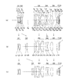
- FIG. 3 is a cross-sectional view along the optical axis showing the optical configuration of the zoom lens according to Example 1 when the first object is in focus, where (a) is a wide-angle end, (b) is an intermediate end, and (c) is a cross-section at a telephoto end.
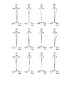
- FIG. 6 is a diagram illustrating spherical aberration (SA), astigmatism (AS), distortion (DT), and lateral chromatic aberration (CC) when the first object is in focus in the zoom lens according to Example 1; (d) is an aberration diagram at the wide-angle end, (e) to (h) are intermediate, and (i) to (l) are aberration diagrams at the telephoto end.
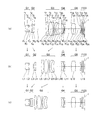
- FIG. 6 is a cross-sectional view along an optical axis showing an optical configuration of the zoom lens according to Example 2 when the first object is focused, where (a) is a wide-angle end, (b) is an intermediate end, and (c) is a cross-section at a telephoto end.
- SA spherical aberration
- AS astigmatism
- DT distortion
- CC lateral chromatic aberration
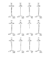
- FIG. 10 is a diagram illustrating spherical aberration (SA), astigmatism (AS), distortion (DT), and lateral chromatic aberration (CC) when the first object is in focus in the zoom lens according to Example 2; (d) is an aberration diagram at the wide-angle end, (e) to (h) are intermediate, and (i) to (l) are aberration diagrams at the telephoto end.
- FIG. 6 is a cross-sectional view taken along the optical axis showing the optical configuration of the zoom lens according to Example 3 when the first object is focused, in which (a) is a wide-angle end, (b) is an intermediate end, and (c) is a cross-section at a telephoto end.
- FIG. 10 is a diagram illustrating spherical aberration (SA), astigmatism (AS), distortion (DT), and lateral chromatic aberration (CC) when the first object is in focus in the zoom lens according to Example 3; (d) is an aberration diagram at the wide-angle end, (e) to (h) are intermediate, and (i) to (l) are aberration diagrams at the telephoto end.
- FIG. 6 is a cross-sectional view along an optical axis showing an optical configuration of a zoom lens according to Example 4 when focusing on a first object, where (a) is a wide-angle end, (b) is an intermediate end, and (c) is a cross-section at a telephoto end.
- FIG. 7A is a diagram illustrating spherical aberration (SA), astigmatism (AS), distortion (DT), and lateral chromatic aberration (CC) when the first object is in focus in the zoom lens according to Example 4; (d) is an aberration diagram at the wide-angle end, (e) to (h) are intermediate, and (i) to (l) are aberration diagrams at the telephoto end.
- FIG. 10 is a cross-sectional view along an optical axis showing an optical configuration of the zoom lens according to Example 5 when the first object is in focus, where (a) is a wide-angle end, (b) is a middle, and (c) is a cross-section at a telephoto end.
- FIG. 10 is a diagram illustrating spherical aberration (SA), astigmatism (AS), distortion (DT), and lateral chromatic aberration (CC) when the first object is in focus in the zoom lens according to Example 5; (d) is an aberration diagram at the wide-angle end, (e) to (h) are intermediate, and (i) to (l) are aberration diagrams at the telephoto end.
- FIG. 10 is a cross-sectional view along the optical axis showing an optical configuration of the zoom lens according to Example 6 when the first object is focused, where (a) is a wide-angle end, (b) is a middle, and (c) is a cross-section at a telephoto end.
- FIG. 10 is a diagram illustrating spherical aberration (SA), astigmatism (AS), distortion (DT), and lateral chromatic aberration (CC) when the first object is in focus in the zoom lens according to Example 6; (d) is an aberration diagram at the wide-angle end, (e) to (h) are intermediate, and (i) to (l) are aberration diagrams at the telephoto end.
- FIG. 10 is a cross-sectional view along an optical axis showing an optical configuration of the zoom lens according to Example 7 when the first object is focused, where (a) is a wide-angle end, (b) is an intermediate end, and (c) is a cross-section at a telephoto end.
- FIGS. 9A and 9B are cross-sectional views along an optical axis showing an optical configuration of the zoom lens according to Example 8 when the first object is focused, where FIG. 9A is a wide-angle end, FIG. 9B is a middle, and FIG. FIG. FIG.
- FIG. 9A is a diagram illustrating spherical aberration (SA), astigmatism (AS), distortion (DT), and lateral chromatic aberration (CC) when the first object is focused on a zoom lens according to Example 8; (d) is an aberration diagram at the wide-angle end, (e) to (h) are intermediate, and (i) to (l) are aberration diagrams at the telephoto end.
- FIG. 10 is a cross-sectional view taken along an optical axis showing an optical configuration of the zoom lens according to Example 9 when the first object is in focus, where (a) is a wide-angle end, (b) is an intermediate end, and (c) is a cross-section at a telephoto end.
- FIG. 10A is a diagram illustrating spherical aberration (SA), astigmatism (AS), distortion (DT), and lateral chromatic aberration (CC) when the first object is focused on a zoom lens according to Example 9; (d) is an aberration diagram at the wide-angle end, (e) to (h) are intermediate, and (i) to (l) are aberration diagrams at the telephoto end.
- FIG. 14 is a cross-sectional view taken along the optical axis showing the optical configuration of the zoom lens according to Example 10 when the first object is in focus, where (a) is a wide-angle end, (b) is an intermediate end, and (c) is a cross-section at a telephoto end.
- FIG. 14 is a diagram illustrating spherical aberration (SA), astigmatism (AS), distortion (DT), and lateral chromatic aberration (CC) when the first object is in focus in the zoom lens according to Example 10; (d) is an aberration diagram at the wide-angle end, (e) to (h) are intermediate, and (i) to (l) are aberration diagrams at the telephoto end.
- FIG. 14 is a cross-sectional view taken along the optical axis showing the optical configuration of the zoom lens according to Example 11 when the first object is in focus, where (a) is a wide-angle end, (b) is an intermediate end, and (c) is a cross-section at a telephoto end.
- FIG. 14 is a diagram illustrating spherical aberration (SA), astigmatism (AS), distortion (DT), and lateral chromatic aberration (CC) when the first object is in focus in the zoom lens according to Example 11; (d) is an aberration diagram at the wide-angle end, (e) to (h) are intermediate, and (i) to (l) are aberration diagrams at the telephoto end.
- FIG. 14 is a cross-sectional view taken along the optical axis showing the optical configuration of the zoom lens according to Example 12 when the first object is in focus, where (a) is a wide-angle end, (b) is an intermediate end, and (c) is a cross-section at a telephoto end.
- SA spherical aberration
- AS astigmatism
- DT distortion
- CC lateral chromatic aberration
- FIG. 14 is a diagram showing spherical aberration (SA), astigmatism (AS), distortion (DT), and lateral chromatic aberration (CC) when the first object is in focus in the zoom lens according to Example 12; (d) is an aberration diagram at the wide-angle end, (e) to (h) are intermediate, and (i) to (l) are aberration diagrams at the telephoto end.
- FIG. 14 is a cross-sectional view taken along an optical axis showing an optical configuration of the zoom lens according to Example 13 when the first object is focused, in which (a) is a wide-angle end, (b) is a middle, and (c) is a cross-section at a telephoto end.
- FIG. 14 is a diagram illustrating spherical aberration (SA), astigmatism (AS), distortion (DT), and lateral chromatic aberration (CC) when the first object is in focus in the zoom lens according to Example 13; (d) is an aberration diagram at the wide-angle end, (e) to (h) are intermediate, and (i) to (l) are aberration diagrams at the telephoto end.
- FIG. 17 is a cross-sectional view taken along the optical axis showing the optical configuration of the zoom lens according to Example 14 when the first object is in focus, where (a) is a wide-angle end, (b) is a middle, and (c) is a cross-section at a telephoto end.
- SA spherical aberration
- AS astigmatism
- DT distortion
- CC lateral chromatic aberration
- the zoom imaging apparatus includes a mount unit, a zoom lens that forms an image of light incident from the mount unit, and an image sensor that is disposed at an image formation position.
- the zoom lens includes a plurality of lens groups. And a focus lens group, and satisfy the following conditional expressions (1) and (2).
- the mount side is the object side
- the image sensor side is the image side
- f Lt and f Lw are the focal lengths of the zoom lens when focused on the first object
- f Lt is the focal length at the telephoto end
- f Lw is the focal length at the wide angle end
- y W7d and y w7d ' is first given ray a ray height of the first predetermined light beam at a position intersecting the image plane
- y w7d ' is the beam height in the defocused state
- the defocused state is a state in which the focus lens group is moved by ⁇ s1 in a state in which the first object is focused
- ⁇ s1 f Lw ⁇ 0.005
- Securing the zoom ratio so as not to fall below the lower limit of conditional expression (1) makes it possible to obtain an image of a desired size without replacing the adapter as in the prior art.
- the optical device is an endoscope
- an image having a size desired by the person performing the operation can be displayed on the television monitor.
- Conditional expression (2) is a conditional expression regarding the change amount ⁇ y (change amount of the image height).
- Y w7d and y w7d ′ in the conditional expression (2) will be described with reference to FIG. 2A is a view showing the entire zoom lens, and FIG. 2B is an enlarged view showing the vicinity of the image plane.
- Lw7 represents the first predetermined light beam
- LA represents the most object side lens of the zoom lens
- Fo represents the focus lens group.
- FIG. 2 is a diagram showing a state in which the image height changes due to the movement of the focus lens group Fo.
- P1 is the position of the focus lens group Fo when the first object is focused.
- P2 is a position where the focus lens group Fo is moved by a minute amount ⁇ S.
- the movement of the focus lens group Fo is exaggerated in FIG.
- the first predetermined light beam L w7 is a light beam having an angle of view of 7 degrees at the wide angle end.
- the first predetermined light beam L w7 passes through the center of the lens surface on the object side of the lens LA.
- the focus lens group Fo In a state where the position of the focus lens group Fo coincides with P1, the light beam incident on the focus lens group Fo travels as indicated by the solid line and reaches the image position.
- the image height at this time is y w7d . From this state, the focus lens group Fo is caused to perform a wobbling operation. As a result, the focus lens group Fo moves to the position P2.
- the light beam incident on the focus lens group Fo travels as indicated by a broken line and reaches the image position.
- the image height at this time is y w7d ′ .
- the image height varies between y w7d and y w7d ′ according to the position of the focus lens group Fo.
- the focus lens group Fo In autofocus, the focus lens group Fo is made to perform a wobbling operation, and the focus is always maintained. Therefore, in autofocus, it is required that the amount of change ⁇ y is small when the focus lens group Fo is moved. By satisfying conditional expression (2), it is possible to suppress an increase in the amount of change ⁇ y at the wide-angle end.
- the size of the image can be freely changed, and when the autofocus is performed on the image of a desired size, the change is achieved. It is possible to perform autofocus while suppressing an increase in the amount ⁇ y.
- conditional expression (2) instead of conditional expression (2), the following conditional expression (2 ′) should be satisfied.
- conditional expression (2 ′′) instead of conditional expression (2).
- y t5d ′ are the heights of the second predetermined light rays at the position where the second predetermined light rays intersect the image plane
- y t5d is the light ray height when focused on the first object
- y t5d ' is the beam height in the defocused state
- the second predetermined light beam is a light beam having a field angle of 5 degrees at the telephoto end, and passes through the center of the lens surface closest to the object side of the zoom lens, It is.
- conditional expression (3) instead of conditional expression (3), the following conditional expression (3 ′) should be satisfied.
- conditional expression (3 ′′) instead of conditional expression (3).
- the plurality of lens groups have a movable lens group, and the focus lens group is located on the image side with respect to the movable lens group.
- the imaging magnification can be changed by the movable lens group.
- the change amount of the image position and the change amount of the image height due to the movement of the focus lens group greatly change according to the movement state of the movable lens group.
- the change in the image position and the change in the image height due to the movement of the focus lens group are greatly influenced by the movement of the movable lens group.
- the focus lens group is positioned closer to the image side than the movable lens group. By doing so, the influence of the movement of the movable lens group can be almost ignored. As a result, an increase in the change amount ⁇ y can be suppressed in the range from the wide-angle end to the telephoto end.
- Focus sensitivity does not change significantly in the range from the wide-angle end to the telephoto end. Since the change in focus sensitivity is small, it is easy to control the movement of the focus lens group. Focus sensitivity is an amount indicating the amount of movement of the image plane relative to the amount of movement of the focus lens group.
- the height of the axial ray is low.
- the focus lens group closer to the image side than the movable lens group, the height of the on-axis light beam passing through the focus lens group is lowered. Therefore, it becomes easy to suppress the occurrence of spherical aberration.
- ⁇ ctw (1- ⁇ fcw ⁇ ⁇ fcw ) ⁇ ⁇ w ' ⁇ ⁇ w ', ⁇ fcw and ⁇ w ′ are lateral magnifications at the wide-angle end when the first object is focused, ⁇ fcw is the lateral magnification of the focus lens group, and ⁇ w ′ is closer to the image side than the focus lens group.
- the first object is an object when the object distance is 1000 mm
- the object point distance is the distance from the lens surface closest to the object of the zoom lens to the object It is.
- Conditional expression (4) relates to the focus sensitivity at the wide-angle end.
- the focus sensitivity is an amount indicating the amount of movement of the image plane with respect to the amount of movement of the focus lens group.
- conditional expression (4) By exceeding the lower limit value of conditional expression (4), it is possible to suppress an increase in the amount of movement of the focus lens group during focusing. As a result, fluctuations in astigmatism during focusing can be suppressed. In addition, since an increase in the amount of movement of the focus lens group can be suppressed, the movement space of the focus lens group can be reduced. As a result, the zoom lens can be miniaturized and the zoom imaging apparatus can be miniaturized.
- conditional expression (4 ′) should be satisfied. 0.555 ⁇
- conditional expression (4 ′′) is satisfied instead of conditional expression (4). 0.555 ⁇
- f fc is the focal length of the focus lens group
- f Lw is a focal length at the wide-angle end of the zoom lens when focused on the first object
- the first object is an object when the object distance is 1000 mm
- the object point distance is the distance from the lens surface closest to the object of the zoom lens to the object It is.
- Conditional expression (5) is a ratio of two focal lengths. One is the focal length of the focus lens group, and the other is the focal length of the zoom lens. The focal length of this zoom lens is the focal length at the wide-angle end when the first object is focused.
- conditional expression (5) By exceeding the lower limit value of conditional expression (5), the Petzval sum can be set well in the focus lens group, and astigmatism can be corrected well. Thereby, good optical performance can be maintained.
- conditional expression (5) instead of conditional expression (5), the following conditional expression (5 ′) should be satisfied. -4 ⁇ f fc / f Lw ⁇ -0.5 (5 ') Furthermore, it is more preferable to satisfy the following conditional expression (5 ′′) instead of conditional expression (5). ⁇ 2.4 ⁇ f fc / f Lw ⁇ 0.8 (5 ′′)
- d pg and d fc are thicknesses on the optical axis of the lens group
- d pg is the thickness of the lens unit having the largest positive refractive power among the thicknesses of the lens unit located on the object side of the focus lens unit
- d fc is the thickness of the focus lens group
- Conditional expression (6) is the ratio of the thickness of the two lens groups on the optical axis.
- One is the thickness of the predetermined positive lens group, and the other is the thickness of the focus lens group.
- the predetermined positive lens group is a lens group having the largest positive refractive power among the lens groups located on the object side of the focus lens group.
- the thickness is the thickness on the optical axis.
- the axial ray height is higher on the object side than the focus lens group.
- a lens group having the largest positive refractive power is arranged to correct the aberration.
- conditional expression (6) the thickness of the lens unit having the largest positive refractive power does not become too thick. Therefore, falling below the upper limit value of conditional expression (6) is effective in shortening the overall length of the optical system.
- conditional expression (6) instead of conditional expression (6), the following conditional expression (6 ′) should be satisfied. 2.7 ⁇ d pg / d fc ⁇ 22 (6 ′) Furthermore, it is more preferable that the following conditional expression (6 ′′) is satisfied instead of conditional expression (6). 3.9 ⁇ d pg / d fc ⁇ 20 (6 ′′)
- the lens group having negative refractive power that satisfies the following conditional expression (7) is located closer to the object side than the lens group having positive refractive power.
- d ng and d pg are the thicknesses on the optical axis of the lens group
- d ng is the thickness of the lens unit having the largest negative refractive power among the thicknesses of the lens unit located on the object side of the focus lens unit
- d pg is the thickness of the lens unit having the largest positive refractive power among the thicknesses of the lens unit located on the object side of the focus lens unit
- Conditional expression (7) relates to the ratio of the thickness on the optical axis of the two lens groups.
- One is the thickness of a predetermined positive lens group, and the other is the thickness of a predetermined negative lens group.
- the predetermined positive lens group is a lens group having the largest positive refractive power among the lens groups located on the object side of the focus lens group.
- the predetermined negative lens group is a lens group having the largest negative refracting power among the lens groups located closer to the object side than the focus lens group.
- Conditional expression (7) is a conditional expression for satisfactorily correcting spherical aberration while suppressing an increase in the total length of the optical system.
- the total length of the optical system can be shortened by exceeding the lower limit value of conditional expression (7).
- conditional expression (7) By falling below the upper limit value of conditional expression (7), it is possible to satisfactorily correct spherical aberration.
- conditional expression (7) instead of conditional expression (7), the following conditional expression (7 ′) should be satisfied. 0.15 ⁇ d ng / d pg ⁇ 0.5 (7 ′) Furthermore, it is better to satisfy the following conditional expression (7 ′′) instead of conditional expression (7). 0.17 ⁇ d ng / d pg ⁇ 0.35 (7 ′′)
- ⁇ fc and ⁇ L1 are effective diameters at the wide-angle end when focusing on the first object
- ⁇ fc is the effective diameter of the lens surface located closest to the object side of the focus lens group
- ⁇ L1 is the effective diameter of the lens surface located closest to the object side of the zoom lens
- the first object is an object when the object distance is 1000 mm
- the object point distance is the distance from the lens surface closest to the object of the zoom lens to the object
- the effective diameter is the maximum diameter of the target lens surface in the range through which light rays contributing to image formation pass, It is.
- Conditional expression (8) relates to the ratio of the two effective diameters.
- One is the effective diameter of the lens surface located closest to the object side of the focus lens group, and the other is the effective diameter of the lens surface located closest to the object side of the zoom lens.
- the effective diameter of the zoom lens is preferably such that the optical path of the exit pupil is guided to the image sensor with little or no vignetting, and at the same time miniaturization is achieved.
- conditional expression (8) By exceeding the lower limit value of conditional expression (8), it is possible to prevent the lens group closest to the object side from becoming large. Thus, exceeding the lower limit value of conditional expression (8) is advantageous for downsizing of the optical system. As a result, it is possible to satisfactorily correct spherical aberration while achieving downsizing of the optical system.
- conditional expression (8) By falling below the upper limit value of conditional expression (8), it is possible to correct spherical aberration and coma aberration in the focus lens group while preventing an increase in size of the focus lens group.
- conditional expression (8) it is preferable to satisfy the following conditional expression (8 ′). 1 ⁇ fc / ⁇ L1 ⁇ 2.5 (8 ′) Further, it is more preferable that the following conditional expression (8 ′′) is satisfied instead of conditional expression (8). 1.1 ⁇ fc / ⁇ L1 ⁇ 2 (8 ′′)
- f ng is the focal length of the lens unit having the largest negative refractive power among the focal lengths of the lens unit located on the object side of the focus lens unit
- f pg is the focal length of the lens unit having the largest positive refractive power among the focal lengths of the lens unit located on the object side of the focus lens unit
- Conditional expression (9) relates to the ratio of the focal lengths of the two lens groups.
- One is the focal length of the predetermined negative lens group, and the other is the focal length of the predetermined positive lens group.
- the predetermined negative lens group is a lens group having the largest negative refracting power among the lens groups located closer to the object side than the focus lens group.
- the predetermined positive lens group is a lens group having the largest positive refractive power among the lens groups located on the object side of the focus lens group.
- conditional expression (9) the refractive power of the predetermined negative lens group and the refractive power of the predetermined positive lens group can be balanced.
- the Petzval sum can be set satisfactorily, astigmatism can be corrected satisfactorily. Thereby, good optical performance can be maintained.
- conditional expression (9 ′) should be satisfied. ⁇ 5 ⁇ f ng / f pg ⁇ 0.9 (9 ′) Furthermore, it is more preferable that the following conditional expression (9 ′′) is satisfied instead of conditional expression (9). -3 ⁇ f ng / f pg ⁇ -1.1 (9 '')
- f ng is the focal length of the lens unit having the largest negative refractive power among the focal lengths of the lens unit located on the object side of the focus lens unit
- f Lt is the focal length at the telephoto end of the zoom lens when focused on the first object
- the first object is an object when the object distance is 1000 mm
- the object point distance is the distance from the lens surface closest to the object of the zoom lens to the object It is.
- Conditional expression (10) relates to the ratio of the focal lengths of the two lens groups.
- One is the focal length of the lens group having the largest negative refractive power among the focal lengths of the lens group located on the object side of the focus lens group, and the other is at the telephoto end of the zoom lens when focused on the first object.
- the focal length is the focal length of the lens group having the largest negative refractive power among the focal lengths of the lens group located on the object side of the focus lens group, and the other is at the telephoto end of the zoom lens when focused on the first object.
- conditional expression (10 ′) should be satisfied. ⁇ 3 ⁇ f ng / f Lt ⁇ 0.25 (10 ′) Furthermore, it is more preferable that the following conditional expression (10 ′′) is satisfied instead of conditional expression (10). ⁇ 1.7 ⁇ f ng / f Lt ⁇ 0.3 (10 ′′)
- ⁇ ctt (1- ⁇ fct ⁇ ⁇ fct ) ⁇ ⁇ t ' ⁇ ⁇ t '
- ⁇ ctw (1- ⁇ fcw ⁇ ⁇ fcw ) ⁇ ⁇ w ' ⁇ ⁇ w '
- ⁇ fct and ⁇ t ′ are lateral magnifications at the telephoto end when the first object is focused
- ⁇ fct is the lateral magnification of the focus lens group
- ⁇ t ′ is the image side from the focus lens group.
- Lateral magnification of the lens group located at ⁇ fcw and ⁇ w ′ are lateral magnifications at the wide-angle end when the first object is focused, ⁇ fcw is the lateral magnification of the focus lens group, and ⁇ w ′ is the image side from the focus lens group.
- Lateral magnification of the lens group located at The first object is an object when the object distance is 1000 mm, The object point distance is the distance from the lens surface closest to the object of the zoom lens to the object It is.
- Conditional expression (11) relates to the ratio between the focus sensitivity at the telephoto end and the focus sensitivity at the wide-angle end.
- the focus sensitivity is an amount indicating the amount of movement of the image plane with respect to the amount of movement of the focus lens group.
- conditional expression (11 ′) instead of conditional expression (11 ), the following conditional expression (11 ′) should be satisfied. 0.9 ⁇
- ⁇ L1 is the effective diameter of the lens surface located closest to the object side of the zoom lens, and is the effective diameter at the wide-angle end when focused on the first object
- f lt is the focal length at the telephoto end of the zoom lens when focused on the first object
- the first object is an object when the object distance is 1000 mm
- the object point distance is the distance from the lens surface closest to the object of the zoom lens to the object
- the effective diameter is the maximum diameter of the target lens surface in the range through which light rays contributing to image formation pass, It is.
- Conditional expression (12) is a ratio of the effective diameter of the lens surface located closest to the object side of the zoom lens and the focal length of the zoom lens at the telephoto end when the first object is focused.
- the effective diameter of the lens is the maximum diameter in the range through which light rays contributing to image formation at the wide-angle end when focused on the first object, that is, the diameter defined by the peripheral light rays.
- the effective diameter of the lens surface located closest to the object side of the zoom lens can be reduced, so that the optical system can be reduced in size.
- conditional expression (12 ′) should be satisfied. 0.04 ⁇ L1 / f lt ⁇ 0.18 (12 ′) Furthermore, it is more preferable that the following conditional expression (12 ′′) is satisfied instead of conditional expression (12). 0.05 ⁇ L1 / f lt ⁇ 0.15 (12 ′′)
- the focus lens group has negative refractive power
- the plurality of lens groups have at least one lens group having negative refractive power
- a lens group having negative refractive power can be used for zooming.
- the zoom ratio can be easily increased.
- the final lens group is disposed closest to the image side, and the final lens group includes a positive lens disposed closest to the object side and a negative lens disposed closest to the image side. It is preferable to have.
- the final lens group is a lens group arranged closest to the image side in the zoom lens.
- the final lens group by arranging the lenses in order of the positive lens and the negative lens from the object side, the light rays converged by the positive lens can be diverged by the negative lens.
- the angle with respect to the optical axis of the light beam passing through the final lens group can be made gentle. Therefore, the occurrence of off-axis aberrations can be particularly suppressed.
- the focus lens group is preferably a wobbling lens group that performs a wobbling operation along the optical axis with a movement amount smaller than a movement amount at the time of focusing.
- the contrast AF method a wobbling operation is performed to maintain a focused state.
- the change in contrast is always measured.
- the focus lens group is appropriately moved to operate again to focus again.
- the entire length of the zoom lens is fixed.
- the entire zoom imaging device becomes large. Therefore, by fixing the entire length of the zoom lens, it is possible to prevent the zoom imaging apparatus from being enlarged and to be manufactured easily.
- r fcff is the radius of curvature of the object side lens surface of the lens located closest to the object side in the focus lens group
- r fcfb is the radius of curvature of the image side lens surface of the lens located closest to the image side in the focus lens group
- Conditional expression (13) relates to the shape of the focus lens group.
- the shape of the focus lens group becomes a shape suitable for correcting spherical aberration. Therefore, it is possible to suppress the fluctuation of spherical aberration during focusing.
- conditional expression (13 ′) instead of conditional expression (13).
- conditional expression (13 ) ⁇ 4 ⁇ (r fcff + r fcfb ) / (r fcff ⁇ r fcfb ) ⁇ 4 (13 ′)
- conditional expression (13 ′′) is satisfied instead of conditional expression (13). ⁇ 3 ⁇ (r fcff + r fcfb ) / (r fcff ⁇ r fcfb ) ⁇ 2 (13 ′′)
- r lf is the radius of curvature of the object side lens surface of the lens located closest to the image side
- r lb is the radius of curvature of the image side lens surface of the lens located closest to the image side
- Conditional expression (14) relates to the shape of the lens located closest to the image side.
- Astigmatism can be satisfactorily corrected by exceeding the lower limit of conditional expression (14). As a result, good optical performance can be maintained. By falling below the upper limit value of conditional expression (14), spherical aberration can be corrected well. As a result, good optical performance can be maintained.
- conditional expression (14 ′) instead of conditional expression (14).
- conditional expression (14 ′) instead of conditional expression (14).
- conditional expression (14 ′) instead of conditional expression (14).
- conditional expression (14 ′′) instead of conditional expression (14).
- the zoom imaging apparatus of the present embodiment includes a mount unit, a zoom lens that forms an image of light incident from the mount unit, and an image sensor that is disposed at the imaging position.
- the fourth lens group is a focus lens group, and only the second lens group and the fourth lens group are used for zooming from the wide-angle end to the telephoto end.
- the first lens group, the third lens group, and the fifth lens group move and are fixed.
- the zoom lens includes, in order from the object side, a first lens group having a positive refractive power, a second lens group having a negative refractive power, and a third lens having a positive refractive power. It includes a lens group, a fourth lens group having negative refractive power, and a fifth lens group having positive refractive power (hereinafter referred to as “first configuration”).
- the zoom imaging apparatus of the present embodiment includes a mount unit, a zoom lens that forms an image of light incident from the mount unit, and an image sensor that is disposed at the imaging position.
- the fourth lens group is a focus lens group, and only the second lens group and the third lens group move during zooming from the wide-angle end to the telephoto end, and the first lens The group, the fourth lens group, and the fifth lens group are fixed.
- the zoom lens includes, in order from the object side, a first lens group, a second lens group having a negative refractive power, a third lens group having a positive refractive power, and a negative lens group.
- the lens unit includes a fourth lens group having a refractive power and a fifth lens group having a positive refractive power (hereinafter referred to as “second configuration”).
- the zoom imaging apparatus of the present embodiment includes a mount unit, a zoom lens that forms an image of light incident from the mount unit, and an image sensor that is disposed at the imaging position.
- the third lens group is a focus lens group, and only the first lens group and the second lens group move during zooming from the wide-angle end to the telephoto end, and the third lens group and the fourth lens group It is fixed.
- the zoom lens includes, in order from the object side, a first lens group having a negative refractive power, a second lens group having a positive refractive power, and a third lens having a negative refractive power.
- the lens unit includes a lens unit and a fourth lens unit having a positive refractive power (hereinafter referred to as “third configuration”).
- the zoom lens having the first configuration, the zoom lens having the second configuration, and the zoom lens having the third configuration can all be used as an imaging optical system for an endoscope.
- the endoscope imaging optical system When the endoscope imaging optical system is combined with the endoscope optical system, the entrance pupil position is restricted.
- an imaging optical system for an endoscope does not have an aperture stop. Therefore, the aperture of the imaging light beam is determined by the exit pupil diameter of the endoscope optical system.
- the eye point of the endoscope optical system is generally a position where there is no problem in visual observation, for example, a position several mm from the end face of the eyepiece.
- the focus lens group is the fourth lens group in the first configuration and the second configuration, and the focus lens group is the third lens group in the third configuration.
- the position of the focus lens group can be moved away from the entrance pupil position, so that the angle of the light beam incident on the focus lens group with respect to the optical axis can be reduced.
- an increase in the change amount ⁇ y can be suppressed when the focus lens group is moved.
- the refractive power of the focus lens group is negative, the focus sensitivity can be increased. As a result, an increase in the amount of movement of the focus lens group during focusing can be suppressed.
- a fifth lens group having positive refractive power is disposed on the image side of the focus lens group (fourth lens group).
- the focus lens group A fourth lens group having a positive refractive power is disposed on the image side of the third lens group.
- a lens group having a positive refractive power is arranged after a lens group having a negative refractive power (focus lens group). Therefore, it is possible to suppress a change in the angle of view during focusing.
- the movement of the lens group in each configuration is as follows.
- the first configuration only the second lens group and the fourth lens group move, and the first lens group, the third lens group, and the fifth lens group are fixed.
- the second configuration only the second lens group and the third lens group move, and the first lens group, the fourth lens group, and the fifth lens group are fixed.
- the third configuration only the first lens group and the second lens group move, and the third lens group and the fourth lens group are fixed.
- the second lens group and the third lens group become main variators.
- the first lens group and the second lens group become main variators.
- the change amount of the image position and the change amount of the image height due to the movement of the focus lens group greatly change according to the movement state of the main variator.
- the change in the image position and the change in the image height due to the movement of the focus lens group are greatly influenced by the movement state of the main variator.
- the focus lens group is the fourth lens group.
- the focus lens group is the third lens group.
- the focus lens group is arranged after the main variator. Therefore, the influence of the main variator can be ignored, so that the focus sensitivity does not change greatly. Since the change in focus sensitivity is small, it is easy to control the movement of the focus lens group.
- the lens diameter can be reduced by the second lens group and the fourth lens group. Therefore, the optical system can be made compact by moving the second lens group and the fourth lens group. Further, by using two lens groups that move during zooming, it is possible to relatively easily control the movement of the lens groups and the mechanical configuration.
- the zoom imaging apparatus of the present embodiment includes a mount unit, a zoom lens that forms an image of light incident from the mount unit, and an image sensor that is disposed at the imaging position. It has a lens group and a focus lens group, and satisfies the following conditional expressions (1) and (15).
- the mount side is the object side
- the image sensor side is the image side
- f Lt and f Lw are the focal lengths of the zoom lens when focused on the first object
- f Lt is the focal length at the telephoto end
- f Lw is the focal length at the wide angle end
- y W7d and y w7d ' is first given ray a ray height of the first predetermined light beam at a position intersecting the image plane
- y w7d ' is the beam height in the defocused state
- conditional expression (1) Since the technical significance of conditional expression (1) has already been explained, explanation here is omitted.
- Conditional expression (15) represents how much the change in the image height is conspicuous on the image sensor when the focus lens group fluctuates slightly. Since the amount of change in image height is divided by the pixel pitch, the smaller the pixel pitch, the more noticeable the change in image height. Further, conditional expression (15) reflects that the image pitch changes more conspicuously as the number of pixels of the image sensor increases because the pixel pitch becomes finer as the total number of pixels increases for the same sensor size.
- conditional expressions (1) and (15) By satisfying conditional expressions (1) and (15), the size of the image can be freely changed, and the amount of change ⁇ y increases when autofocus is performed on an image of a desired size. It is possible to perform auto-focusing with suppressed.
- conditional expression (15 ′) should be satisfied.
- conditional expression (15 ′′) is satisfied instead of conditional expression (15).
- the positive and negative refractive powers are based on the paraxial radius of curvature.
- the zoom lenses of the following embodiments are connected to the eyepieces of optical devices when in use.
- an aperture stop is disposed in the optical system on the optical apparatus side, no aperture stop is provided on the zoom lens side.
- an aperture stop is required.
- the virtual diaphragm in the following description of the embodiments is an aperture diaphragm provided for design. Therefore, in an actual zoom lens, the aperture stop does not physically exist.
- an aperture for example, a flare aperture
- shielding unnecessary light may be arranged at the position of the virtual aperture.
- the position of the first object is a position when the object point distance is 1000 mm.
- the position of the second object is a position when the object point distance is 333.33 mm. At the position of the second object, the object is closest to the zoom lens.
- FIG. 3 is a cross-sectional view (lens cross-sectional view) along the optical axis showing the optical configuration of the zoom lens of Example 1 when focusing on the first object, in which (a) is a cross-sectional view at the wide-angle end; ) Is a cross-sectional view in the intermediate focal length state, and (c) is a cross-sectional view at the telephoto end.
- F represents a filter
- CG represents a cover glass
- I represents an imaging surface (image surface) of the imaging device.
- CG represents a color separation prism instead of a cover glass.
- FIG. 4 is an aberration diagram of the zoom lens according to Example 1 when the first object is in focus.
- ⁇ is a half angle of view.
- the symbols in the aberration diagrams are the same in the examples described later.
- SA spherical aberration
- AS astigmatism
- DT distortion
- CC chromatomatic aberration
- SA spherical aberration
- AS astigmatism
- DT distortion
- CC lateral chromatic aberration
- (i), (j), (k), and (l) respectively indicate spherical aberration (SA), astigmatism (AS), distortion (DT), and lateral chromatic aberration (CC) at the telephoto end. ing.
- SA spherical aberration
- AS astigmatism
- DT distortion
- CC lateral chromatic aberration
- the zoom lens of Example 1 includes, in order from the object side, a first lens group G1 having a positive refractive power, a second lens group G2 having a negative refractive power, and a positive refractive power.
- the first lens group G1 includes a negative meniscus lens L1 having a convex surface facing the image side, a biconvex lens L2, and a negative meniscus lens L3 having a convex surface facing the image side.
- the biconvex lens L2 and the negative meniscus lens L3 are cemented.
- the virtual aperture is set on the image side surface of the negative meniscus lens L3.
- the second lens group G2 includes a positive meniscus lens L4 having a convex surface directed toward the image side, and a biconcave negative lens L5.
- the positive meniscus lens L4 and the biconcave negative lens L5 are cemented.
- the third lens group G3 includes a biconvex positive lens L6, a biconvex positive lens L7, and a biconcave negative lens L8.
- the biconvex positive lens L7 and the biconcave negative lens L8 are cemented.
- the fourth lens group G4 is composed of a biconcave negative lens L9.
- the fifth lens group G5 includes a biconvex positive lens L10 and a negative meniscus lens L11 having a convex surface directed toward the image side.
- the biconvex positive lens L10 and the negative meniscus lens L11 are cemented.
- the first lens group G1 is fixed, the second lens group G2 is moved to the image side, the third lens group G3 is fixed, and the fourth lens group G4 is an image.
- the fifth lens group G5 is fixed.
- focusing on the subject is performed by moving the fourth lens group G4.
- the biconcave negative lens L9 moves to the image side.
- FIG. 5 is a cross-sectional view along the optical axis showing the optical configuration of the zoom lens of Example 2 when the first object is in focus.
- FIG. 6 is an aberration diagram of the zoom lens of Example 2 when the first object is in focus.
- the zoom lens of Example 2 includes, in order from the object side, a first lens group G1 having a positive refractive power, a second lens group G2 having a negative refractive power, and a positive refractive power.
- the first lens group G1 includes a negative meniscus lens L1 having a convex surface directed toward the image side, a biconvex lens L2, and a biconcave negative lens L3.
- the biconvex lens L2 and the biconcave negative lens L3 are cemented.
- the virtual diaphragm is set on the image side surface of the biconcave negative lens L3.
- the second lens group G2 includes a biconcave negative lens L4 and a positive meniscus lens L5 having a convex surface directed toward the object side.
- the biconcave negative lens L4 and the positive meniscus lens L5 are cemented.
- the third lens group G3 includes a positive meniscus lens L6 having a convex surface facing the image side, a biconvex positive lens L7, a negative meniscus lens L8 having a convex surface facing the image side, and a negative meniscus lens having a convex surface facing the object side.
- L9 and a positive meniscus lens L10 having a convex surface facing the object side.
- the biconvex positive lens L7 and the negative meniscus lens L8 are cemented.
- the negative meniscus lens L9 and the positive meniscus lens L10 are cemented.
- the fourth lens group G4 includes a negative meniscus lens L11 having a convex surface directed toward the image side, and a biconcave negative lens L12.
- the negative meniscus lens L11 and the biconcave negative lens L12 are cemented.
- the fifth lens group G5 includes a biconvex positive lens L13 and a biconcave negative lens L14.
- the first lens group G1 is fixed, the second lens group G2 is moved to the image side, the third lens group G3 is fixed, and the fourth lens group G4 is an image.
- the fifth lens group G5 is fixed.
- focusing on the subject is performed by moving the fourth lens group G4.
- the negative meniscus lens L11 and the biconcave negative lens L12 move to the image side.
- FIG. 7 is a cross-sectional view along the optical axis showing the optical configuration of the zoom lens of Example 3 when the first object is in focus.
- FIG. 8 is an aberration diagram of the zoom lens of Example 3 when the first object is in focus.
- the zoom lens according to the third exemplary embodiment includes, in order from the object side, a first lens group G1 having a positive refractive power, a second lens group G2 having a negative refractive power, and a positive refractive power.
- the first lens group G1 includes a negative meniscus lens L1 having a convex surface directed toward the object side, a biconvex lens L2, and a biconcave negative lens L3.
- the biconvex lens L2 and the biconcave negative lens L3 are cemented.
- the virtual diaphragm is set on the image side surface of the biconcave negative lens L3.
- the second lens group G2 includes a biconcave negative lens L4 and a positive meniscus lens L5 having a convex surface directed toward the object side.
- the biconcave negative lens L4 and the positive meniscus lens L5 are cemented.
- the third lens group G3 includes a biconvex positive lens L6, a biconvex positive lens L7, a biconcave negative lens L8, a negative meniscus lens L9 having a convex surface facing the object side, and a biconvex positive lens L10. .
- the biconvex positive lens L7 and the biconcave negative lens L8 are cemented.
- the negative meniscus lens L9 and the biconvex positive lens L10 are cemented.
- the fourth lens group G4 is composed of a biconcave negative lens L11.
- the fifth lens group G5 includes a biconvex positive lens L12, a biconvex positive lens L13, a negative meniscus lens L14 with a convex surface facing the image side, a positive meniscus lens L15 with a convex surface facing the image side, and a biconcave negative lens. L16.
- the biconvex positive lens L13 and the negative meniscus lens L14 are cemented.
- the first lens group G1 is fixed, the second lens group G2 is moved to the image side, the third lens group G3 is fixed, and the fourth lens group G4 is an image.
- the fifth lens group G5 is fixed.
- the position of the fourth lens group G4 is the same in the intermediate focal length state and the telephoto end.
- focusing on the subject is performed by moving the fourth lens group G4.
- the biconcave negative lens L11 moves to the image side.
- FIG. 9 is a cross-sectional view along the optical axis showing the optical configuration of the zoom lens of Example 4 when the first object is in focus.
- FIG. 10 is an aberration diagram of the zoom lens of Example 4 when the first object is in focus.
- the zoom lens of Example 4 includes, in order from the object side, a first lens group G1 having a positive refractive power, a second lens group G2 having a negative refractive power, and a positive refractive power.
- the first lens group G1 includes a biconvex lens L1 and a biconcave negative lens L2.
- the biconvex lens L1 and the biconcave negative lens L2 are cemented.
- the virtual diaphragm is set on the image side surface of the biconcave negative lens L2.
- the second lens group G2 includes a biconcave negative lens L3 and a positive meniscus lens L4 having a convex surface directed toward the object side.
- the biconcave negative lens L3 and the positive meniscus lens L4 are cemented.
- the third lens group G3 includes a biconvex positive lens L5, a negative meniscus lens L6 having a convex surface directed toward the object side, and a biconvex positive lens L7.
- the negative meniscus lens L6 and the biconvex positive lens L7 are cemented.
- the fourth lens group G4 includes a negative meniscus lens L8 having a convex surface directed toward the object side.
- the fifth lens group G5 includes a biconvex positive lens L9, a biconvex positive lens L10, and a biconcave negative lens L11.
- the biconvex positive lens L10 and the biconcave negative lens L11 are cemented.
- the first lens group G1 is fixed, the second lens group G2 is moved to the image side, the third lens group G3 is fixed, and the fourth lens group G4 is an image.
- the fifth lens group G5 is fixed.
- focusing on the subject is performed by moving the fourth lens group G4.
- the negative meniscus lens L8 moves to the image side.
- the aspheric surfaces are provided on a total of two surfaces of both surfaces of the biconvex positive lens L5.
- FIG. 11 is a cross-sectional view along the optical axis showing the optical configuration of the zoom lens of Example 5 when the first object is in focus.
- FIG. 12 is an aberration diagram of the zoom lens according to Example 5 when the first object is in focus.
- the zoom lens of Embodiment 5 includes, in order from the object side, a first lens group G1 having a positive refractive power, a second lens group G2 having a negative refractive power, and a positive refractive power.
- the first lens group G1 includes a negative meniscus lens L1 having a convex surface facing the image side, a biconvex lens L2, and a negative meniscus lens L3 having a convex surface facing the image side.
- the biconvex lens L2 and the negative meniscus lens L3 are cemented.
- the virtual aperture is set on the image side surface of the negative meniscus lens L3.
- the second lens group G2 includes a biconcave negative lens L4 and a positive meniscus lens L5 having a convex surface directed toward the object side.
- the biconcave negative lens L4 and the positive meniscus lens L5 are cemented.
- the third lens group G3 includes a positive meniscus lens L6 having a convex surface facing the image side, a biconvex positive lens L7, a negative meniscus lens L8 having a convex surface facing the image side, and a negative meniscus lens having a convex surface facing the object side.
- the biconvex positive lens L7 and the negative meniscus lens L8 are cemented.
- the negative meniscus lens L9 and the biconvex positive lens L10 are cemented.
- the fourth lens group G4 includes a negative meniscus lens L11 having a convex surface directed toward the image side, and a biconcave negative lens L12.
- the fifth lens group G5 includes a biconvex positive lens L13 and a negative meniscus lens L14 having a convex surface directed toward the image side.
- the first lens group G1 is fixed, the second lens group G2 is moved to the image side, the third lens group G3 is fixed, and the fourth lens group G4 is an image.
- the fifth lens group G5 is fixed.
- focusing on the subject is performed by moving the fourth lens group G4.
- the negative meniscus lens L11 and the biconcave negative lens L12 move to the image side.
- FIG. 13 is a cross-sectional view along the optical axis showing the optical configuration of the zoom lens of Example 6 when the first object is in focus.
- FIG. 14 is an aberration diagram of the zoom lens according to Example 6 when the first object is in focus.
- the zoom lens of Example 6 includes, in order from the object side, a first lens group G1 having a positive refractive power, a second lens group G2 having a negative refractive power, and a positive refractive power.
- the first lens group G1 includes a negative meniscus lens L1 having a convex surface directed toward the object side, a biconvex lens L2, and a biconcave negative lens L3.
- the biconvex lens L2 and the biconcave negative lens L3 are cemented.
- the virtual diaphragm is set on the image side surface of the biconcave negative lens L3.
- the second lens group G2 includes a biconcave negative lens L4 and a positive meniscus lens L5 having a convex surface directed toward the object side.
- the biconcave negative lens L4 and the positive meniscus lens L5 are cemented.
- the third lens group G3 includes a biconvex positive lens L6, a biconvex positive lens L7, a negative meniscus lens L8 having a convex surface on the image side, a negative meniscus lens L9 having a convex surface on the object side, and an object side.
- the biconvex positive lens L7 and the negative meniscus lens L8 are cemented.
- the negative meniscus lens L9 and the positive meniscus lens L10 are cemented.
- the fourth lens group G4 is composed of a biconcave negative lens L11.
- the fifth lens group G5 includes a biconvex positive lens L12, a biconvex positive lens L13, a negative meniscus lens L14 having a convex surface facing the image side, a negative meniscus lens L15 having a convex surface facing the image side, and an object side.
- the first lens group G1 is fixed, the second lens group G2 is moved to the image side, the third lens group G3 is fixed, and the fourth lens group G4 is an image.
- the fifth lens group G5 is fixed.
- focusing on the subject is performed by moving the fourth lens group G4.
- the biconcave negative lens L11 moves to the image side.
- FIG. 15 is a cross-sectional view along the optical axis showing the optical configuration of the zoom lens of Example 7 when the first object is in focus.
- FIG. 16 is an aberration diagram of the zoom lens of Example 7 when the first object is in focus.
- the zoom lens according to the seventh embodiment includes, in order from the object side, a first lens group G1 having a positive refractive power, a second lens group G2 having a negative refractive power, and a positive refractive power.
- the first lens group G1 includes a negative meniscus lens L1 having a convex surface facing the image side, a biconvex lens L2, and a negative meniscus lens L3 having a convex surface facing the image side.
- the biconvex lens L2 and the negative meniscus lens L3 are cemented.
- the virtual aperture is set on the image side surface of the negative meniscus lens L3.
- the second lens group G2 includes a positive meniscus lens L4 having a convex surface directed toward the image side, and a biconcave negative lens L5.
- the positive meniscus lens L4 and the biconcave negative lens L5 are cemented.
- the third lens group G3 includes a biconvex positive lens L6, a biconvex positive lens L7, and a biconcave negative lens L8.
- the biconvex positive lens L7 and the biconcave negative lens L8 are cemented.
- the fourth lens group G4 is composed of a biconcave negative lens L9.
- the fifth lens group G5 includes a biconvex positive lens L10 and a negative meniscus lens L11 having a convex surface directed toward the image side.
- the biconvex positive lens L10 and the negative meniscus lens L11 are cemented.
- the first lens group G1 is fixed, the second lens group G2 is moved to the image side, the third lens group G3 is fixed, and the fourth lens group G4 is an image.
- the fifth lens group G5 is fixed.
- focusing on the subject is performed by moving the fourth lens group G4.
- the biconcave negative lens L9 moves to the image side.
- FIG. 17 is a cross-sectional view along the optical axis showing the optical configuration of the zoom lens of Example 8 when the first object is in focus.
- FIG. 18 is an aberration diagram of the zoom lens according to Example 8 when the first object is in focus.
- the zoom lens according to the eighth embodiment includes, in order from the object side, a first lens group G1 having a positive refractive power, a second lens group G2 having a negative refractive power, and a positive refractive power.
- the first lens group G1 includes a negative meniscus lens L1 having a convex surface directed toward the object side, a biconvex lens L2, and a biconcave negative lens L3.
- the biconvex lens L2 and the biconcave negative lens L3 are cemented.
- the virtual diaphragm is set on the image side surface of the biconcave negative lens L3.
- the second lens group G2 includes a biconcave negative lens L4 and a positive meniscus lens L5 having a convex surface directed toward the object side.
- the biconcave negative lens L4 and the positive meniscus lens L5 are cemented.
- the third lens group G3 includes a biconvex positive lens L6, a biconvex positive lens L7, a negative meniscus lens L8 having a convex surface on the image side, a negative meniscus lens L9 having a convex surface on the object side, and a biconvex positive Lens L10.
- the biconvex positive lens L7 and the negative meniscus lens L8 are cemented.
- the negative meniscus lens L9 and the biconvex positive lens L10 are cemented.
- the fourth lens group G4 is composed of a biconcave negative lens L11.
- the fifth lens group G5 includes a biconvex positive lens L12, a biconvex positive lens L13, a negative meniscus lens L14 having a convex surface facing the image side, a positive meniscus lens L15 having a convex surface facing the image side, and a biconcave negative lens.
- Lens L16 includes a biconvex positive lens L12, a biconvex positive lens L13, a negative meniscus lens L14 having a convex surface facing the image side, a positive meniscus lens L15 having a convex surface facing the image side, and a biconcave negative lens.
- Lens L16 is a biconvex positive lens L12, a biconvex positive lens L13, a negative meniscus lens L14 having a convex surface facing the image side, a positive meniscus lens L15 having a convex surface facing the image side, and a biconcave negative lens.
- the first lens group G1 is fixed, the second lens group G2 is moved to the image side, the third lens group G3 is fixed, and the fourth lens group G4 is an image.
- the fifth lens group G5 is fixed.
- focusing on the subject is performed by moving the fourth lens group G4.
- the biconcave negative lens L11 moves to the image side.
- FIG. 19 is a cross-sectional view along the optical axis showing the optical configuration of the zoom lens of Example 9 when the first object is in focus.
- FIG. 20 is an aberration diagram of the zoom lens according to Example 9 when the first object is in focus.
- the zoom lens of Example 9 includes, in order from the object side, a first lens group G1 having a positive refractive power, a second lens group G2 having a negative refractive power, and a positive refractive power.
- the first lens group G1 includes a negative meniscus lens L1 having a convex surface facing the object side, a positive meniscus lens L2 having a convex surface facing the object side, and a biconvex positive lens L3.
- the positive meniscus lens L2 and the biconvex positive lens L3 are cemented.
- the virtual diaphragm is set on the image side surface of the biconvex positive lens L3.
- the second lens group G2 includes a biconcave negative lens L4 and a positive meniscus lens L5 having a convex surface directed toward the object side.
- the biconcave negative lens L4 and the positive meniscus lens L5 are cemented.
- the third lens group G3 includes a biconvex positive lens L6, a biconvex positive lens L7, a biconcave negative lens L8, a negative meniscus lens L9 having a convex surface on the object side, and a positive meniscus having a convex surface on the object side.
- Lens L10 Here, the biconvex positive lens L7 and the biconcave negative lens L8 are cemented. Further, the negative meniscus lens L9 and the positive meniscus lens L10 are cemented.
- the fourth lens group G4 is composed of a biconcave negative lens L11.
- the fifth lens group G5 includes a biconvex positive lens L12, a negative meniscus lens L13 having a convex surface facing the image side, and a negative meniscus lens L14 having a convex surface facing the image side.
- the biconvex positive lens L12 and the negative meniscus lens L13 are cemented.
- the first lens group G1 is fixed, the second lens group G2 moves to the image side, the third lens group G3 moves to the object side, and the fourth lens group G4. Is fixed, and the fifth lens group G5 is fixed.
- focusing on the subject is performed by moving the fourth lens group G4.
- the biconcave negative lens L11 moves to the image side.
- FIG. 21 is a cross-sectional view along the optical axis showing the optical configuration of the zoom lens of Example 10 when the first object is in focus.
- FIG. 22 is an aberration diagram of the zoom lens of Example 10 when the first object is in focus.
- the zoom lens of Example 10 includes, in order from the object side, a first lens group G1 having a negative refractive power, a second lens group G2 having a negative refractive power, and a positive refractive power.
- the first lens group G1 includes a positive meniscus lens L1 having a convex surface facing the image side and a negative meniscus lens L2 having a convex surface facing the image side.
- the positive meniscus lens L1 and the negative meniscus lens L2 are cemented.
- the virtual diaphragm is set on the image side surface of the negative meniscus lens L2.
- the second lens group G2 includes a biconcave negative lens L4 and a positive meniscus lens L5 having a convex surface directed toward the object side.
- the biconcave negative lens L4 and the positive meniscus lens L5 are cemented.
- the third lens group G3 includes a positive meniscus lens L5 having a convex surface directed to the image side, a biconvex positive lens L6, a biconcave negative lens L7, a negative meniscus lens L8 having a convex surface directed to the object side, and an object side.
- the biconvex positive lens L6 and the biconcave negative lens L7 are cemented.
- the negative meniscus lens L8 and the positive meniscus lens L9 are cemented.
- the fourth lens group G4 includes a biconcave negative lens L10 and a positive meniscus lens L11 having a convex surface directed toward the object side.
- the biconcave negative lens L10 and the positive meniscus lens L11 are cemented.
- the fifth lens group G5 includes a biconvex positive lens L12, a negative meniscus lens L13 having a convex surface facing the image side, and a negative meniscus lens L14 having a convex surface facing the image side.
- the biconvex positive lens L12 and the negative meniscus lens L13 are cemented.
- the first lens group G1 is fixed, the second lens group G2 moves to the image side, then moves to the object side, and the third lens group G3 moves to the object side.
- the fourth lens group G4 is fixed, and the fifth lens group G5 is fixed.
- focusing on the subject is performed by moving the fourth lens group G4.
- the biconcave negative lens L10 and the positive meniscus lens L11 move to the image side.
- FIG. 23 is a cross-sectional view along the optical axis showing the optical configuration of the zoom lens of Example 11 when the first object is in focus.
- FIG. 24 is an aberration diagram for the zoom lens of Example 11 when the first object was in focus.
- the zoom lens of Example 11 includes, in order from the object side, a first lens group G1 having a negative refractive power, a second lens group G2 having a negative refractive power, and a positive refractive power.
- the first lens group G1 includes a positive meniscus lens L1 having a convex surface facing the image side and a negative meniscus lens L2 having a convex surface facing the image side.
- the positive meniscus lens L1 and the negative meniscus lens L2 are cemented.
- the virtual diaphragm is set on the image side surface of the negative meniscus lens L2.
- the second lens group G2 includes a biconcave negative lens L4 and a positive meniscus lens L5 having a convex surface directed toward the object side.
- the biconcave negative lens L4 and the positive meniscus lens L5 are cemented.
- the third lens group G3 includes a biconvex positive lens L5, a biconvex positive lens L6, a biconcave negative lens L7, a negative meniscus lens L8 having a convex surface on the object side, and a positive meniscus having a convex surface on the object side.
- the biconvex positive lens L6 and the biconcave negative lens L7 are cemented.
- the negative meniscus lens L8 and the positive meniscus lens L9 are cemented.
- the fourth lens group G4 includes a positive meniscus lens L10 having a convex surface facing the image side, and a negative meniscus lens L11 having a convex surface facing the image side.
- the fifth lens group G5 includes a biconvex positive lens L12 and a negative meniscus lens L13 having a convex surface directed toward the image side.
- the first lens group G1 is fixed, the second lens group G2 moves to the image side, then moves to the object side, and the third lens group G3 moves to the object side.
- the fourth lens group G4 is fixed, and the fifth lens group G5 is fixed.
- focusing on the subject is performed by moving the fourth lens group G4.
- the positive meniscus lens L10 and the negative meniscus lens L11 move to the image side.
- FIG. 25 is a cross-sectional view along the optical axis showing the optical configuration of the zoom lens of Example 12 when the first object is in focus.
- FIG. 26 is an aberration diagram for the zoom lens of Example 12 when the first object is in focus.
- the zoom lens of Example 12 includes, in order from the object side, a first lens group G1 having a negative refractive power, a second lens group G2 having a positive refractive power, and a negative refractive power. And a fourth lens group G4 having a positive refractive power.
- the first lens group G1 includes a negative meniscus lens L1 having a convex surface facing the image side, a positive meniscus lens L2 having a convex surface facing the image side, and a biconcave negative lens L3.
- the negative meniscus lens L1, the positive meniscus lens L2, and the biconcave negative lens L3 are cemented.
- the virtual diaphragm is set on the object side of the negative meniscus lens L1.
- the second lens group G2 includes a biconvex positive lens L4, a biconvex positive lens L5, a biconcave negative lens L6, a negative meniscus lens L7 having a convex surface facing the object side, and a biconvex positive lens L8.
- the biconvex positive lens L5 and the biconcave negative lens L6 are cemented.
- the negative meniscus lens L7 and the biconvex positive lens L8 are cemented.
- the third lens group G3 is composed of a biconcave negative lens L9.
- the fourth lens group G4 includes a biconvex positive lens L10 and a biconcave negative lens L11.
- the first lens group G1 moves to the image side, then moves to the object side, the second lens group G2 moves to the object side, and the third lens group G3 is fixed. Yes, the fourth lens group G4 is fixed.
- focusing on the subject is performed by moving the third lens group G3.
- the biconcave negative lens L9 moves to the image side.
- the aspheric surfaces are provided on a total of six surfaces including both surfaces of the biconvex positive lens L4, both surfaces of the biconcave negative lens L9, and both surfaces of the biconvex positive lens L10.
- FIG. 27 is a cross-sectional view along the optical axis showing the optical configuration of the zoom lens of Example 13 when the first object is in focus.
- FIG. 28 is an aberration diagram for the zoom lens of Example 13 upon focusing the first object.
- the zoom lens of Example 13 includes, in order from the object side, a first lens group G1 having a negative refractive power, a second lens group G2 having a positive refractive power, and a negative refractive power. And a fourth lens group G4 having a positive refractive power.
- the first lens group G1 includes a negative meniscus lens L1 having a convex surface facing the image side, a positive meniscus lens L2 having a convex surface facing the image side, and a biconcave negative lens L3.
- the negative meniscus lens L1, the positive meniscus lens L2, and the biconcave negative lens L3 are cemented.
- the virtual diaphragm is set on the object side of the negative meniscus lens L1.
- the second lens group G2 includes a biconvex positive lens L4, a biconvex positive lens L5, a biconcave negative lens L6, a negative meniscus lens L7 having a convex surface facing the object side, and a biconvex positive lens L8.
- the biconvex positive lens L5 and the biconcave negative lens L6 are cemented.
- the negative meniscus lens L7 and the biconvex positive lens L8 are cemented.
- the third lens group G3 is composed of a biconcave negative lens L9.
- the fourth lens group G4 includes a biconvex positive lens L10, a biconvex positive lens L11, and a biconcave negative lens L12.
- the first lens group G1 moves to the image side, then moves to the object side, the second lens group G2 moves to the object side, and the third lens group G3 is fixed. Yes, the fourth lens group G4 is fixed.
- focusing on the subject is performed by moving the third lens group G3.
- the biconcave negative lens L9 moves to the image side.
- FIG. 29 is a cross-sectional view along the optical axis showing the optical configuration of the zoom lens of Example 14 when the first object is in focus.
- FIG. 30 is an aberration diagram for the zoom lens of Example 14 upon focusing on the first object.
- the zoom lens of Example 14 includes, in order from the object side, a first lens group G1 having a negative refractive power, a second lens group G2 having a positive refractive power, and a negative refractive power. And a fourth lens group G4 having a positive refractive power.
- the first lens group G1 includes a negative meniscus lens L1 having a convex surface facing the image side, a positive meniscus lens L2 having a convex surface facing the image side, and a biconcave negative lens L3.
- the negative meniscus lens L1, the positive meniscus lens L2, and the biconcave negative lens L3 are cemented.
- the virtual diaphragm is set on the object side of the negative meniscus lens L1.
- the second lens group G2 includes a biconvex positive lens L4, a positive meniscus lens L5 having a convex surface facing the object side, a negative meniscus lens L6 having a convex surface facing the object side, and a negative meniscus lens having a convex surface facing the object side.
- L7 and a biconvex positive lens L8 are cemented.
- the positive meniscus lens L5 and the negative meniscus lens L6 are cemented.
- the negative meniscus lens L7 and the biconvex positive lens L8 are cemented.
- the third lens group G3 is composed of a biconcave negative lens L9.
- the fourth lens group G4 includes a biconvex positive lens L10 and a negative meniscus lens L11 having a convex surface directed toward the image side.
- the first lens group G1 moves to the image side, then moves to the object side, the second lens group G2 moves to the object side, and the third lens group G3 is fixed. Yes, the fourth lens group G4 is fixed.
- focusing on the subject is performed by moving the third lens group G3.
- the biconcave negative lens L9 moves to the image side.
- r1, r2,... are the curvature radii of the lens surfaces, d1, d2,... Are the thickness or air spacing of each lens, and nd1, nd2,.
- ER is the effective diameter
- * is an aspherical surface.
- f is the focal length of the entire zoom lens system, FNO. Is the F number, FB is the back focus, IH is the image height, ⁇ is the half field angle, f1, f2,...
- the total length is obtained by adding back focus to the distance from the lens front surface to the lens final surface. The back focus represents the distance from the last lens surface to the paraxial image surface in terms of air.
- the wide angle 1, the middle 1, and the telephoto 1 are the wide angle end, the intermediate focal length state, and the telephoto end, respectively, when the first object is focused.
- Wide angle 2, intermediate 2 and telephoto 2 are a wide angle end, an intermediate focal length state, and a telephoto end, respectively, in a state in which the second object is focused.
- the values of IH and ⁇ are not values at the focal length of each state.
- the aspherical shape is expressed by the following equation when the optical axis direction is z, the direction orthogonal to the optical axis is y, the conical coefficient is k, and the aspherical coefficients are A4, A6, A8, and A10. .
- z (y 2 / r) / [1+ ⁇ 1 ⁇ (1 + k) (y / r) 2 ⁇ 1/2 ] + A4y 4 + A6y 6 + A8y 8 + A10y 10
- “en” (n is an integer) indicates “10 ⁇ n ”.
- the symbols of these specification values are common to the numerical data of the examples described later.
- Numerical example 2 Unit mm Surface data Surface number r d nd ⁇ d ER Object ⁇ ⁇ 1 -15.012 0.70 1.88300 40.76 3.5678 2 -16.475 0.50 3.6075 3 52.044 1.70 1.80610 40.92 3.5081 4 -16.001 0.70 1.72151 29.23 3.4058 5 4134.942 Variable 6 -35.115 0.70 1.80610 40.92 3.3334 7 10.106 1.87 1.84666 23.78 3.4484 8 35.596 Variable 3.5458 9 -1832.152 2.27 1.80610 40.92 7.4671 10 -28.959 0.50 7.6195 11 58.441 4.00 1.57135 52.95 7.6161 12 -15.741 0.70 1.74077 27.79 7.5389 13 -87.401 0.78 7.5633 14 12.676 0.80 1.69895 30.13 7.4011 15 9.422 4.41 1.49700 81.61 6.9479 16 199.193 Variable 6.6287 17 -5
- Numerical Example 8 Unit mm Surface data Surface number r d nd ⁇ d ER Object ⁇ ⁇ 1 50.358 1.83 1.57135 52.95 3.8019 2 14.675 1.94 3.5814 3 16.999 1.78 1.80400 46.57 3.5442 4 -29.018 0.70 1.69895 30.13 3.4172 5 70.056 Variable 6 -39.988 0.70 1.88300 40.76 3.3325 7 14.043 1.76 1.84666 23.78 3.4295 8 62.753 Variable 3.5483 9 79.109 2.42 1.88300 40.76 7.6446 10 -38.911 0.30 7.7223 11 28.814 4.00 1.69680 55.53 7.5858 12 -21.528 0.70 2.00330 28.27 7.3319 13 -390.775 0.30 7.2042 14 16.073 0.80 1.72825 28.46 6.9075 15 10.936 3.78 1.48749 70.23 6.5115 16 -173.628 Variable 6.1797 17 -50.070
- Numerical example 12 Unit mm Surface data Surface number r d nd ⁇ d ER Object ⁇ ⁇ 1 ⁇ Variable 2 -15.186 0.70 1.65160 58.55 3.3171 3 -25.413 1.85 1.92286 18.90 3.4536 4 -8.959 0.70 1.74077 27.79 3.6622 5 78.034 Variable 3.8687 6 * 22.697 2.75 1.86400 40.58 7.5733 7 * -110.383 0.30 7.524 8 28.492 2.37 1.88300 40.76 7.4179 9 -226.154 0.70 1.84666 23.78 7.2081 10 54.929 0.50 6.9947 11 41.913 0.70 1.78472 25.68 6.8682 12 10.000 4.25 1.49700 81.61 6.408 13 -36.869 Variable 6.3082 14 * -102.480 0.70 1.49700 81.61 5.259 15 * 22.944 Variable 5.06 16 * 10.714 2.93 1.86400 40.58 4.3437 17 * -18
- FIG. 31 shows a state in which the zoom imaging apparatus of the present embodiment is connected to an optical device.
- FIG. 31 shows a case where the optical device is a rigid endoscope.
- the rigid endoscope 10 includes a scope-side light guide 1, an objective lens 2, a relay lens 3, an eyepiece lens 4, and an optical element 5.
- An eyepiece lens 4 is disposed on the eyepiece 6 of the rigid endoscope 10.
- a light source device 8 is connected to the rigid endoscope 10 via a light guide cable 7.
- the light emitted from the light source device 8 is transmitted to the incident portion of the scope side light guide 1 by the light guide cable 7.
- the light guide cable 7 and the scope side light guide 1 are directly connected or connected via the optical element 5.
- the optical element 5 is an element that converts the NA of light emitted from the light guide cable 7.
- the illumination light incident on the scope-side light guide 1 is transmitted to the distal end of the rigid endoscope 10. Illumination light is applied to the subject from the distal end of the rigid endoscope 10.
- a subject image I 1 is formed by the objective lens 2.
- the subject image I 1 is relayed by the relay lens 3, and the subject image I 2 is formed at a predetermined position.
- the user can observe the subject visually through the eyepiece 6.
- the zoom imaging device 20 of the present embodiment is connected to the eyepiece unit 6.
- the zoom imaging device 20 includes a mount unit 21, a zoom lens 22, and an image sensor 23.
- the zoom lens of Example 1 is used as the zoom lens 22. Since the zoom lens of Example 1 is an optical system suitable for a system (three-plate system) that performs imaging using three imaging elements, a prism is disposed in front of the imaging element 23.
- a system single plate type that performs imaging using one image sensor can be used.
- a screw type mount, a bayonet type mount, or the like is used as the mount portion 21 .
- the rigid endoscope 10 and the zoom imaging device 20 can be connected to the eyepiece 6 by using a screw type mount, a bayonet type mount, or the like.
- the rigid endoscope 10 By connecting the rigid endoscope 10 and the zoom imaging device 20, light from the subject enters the zoom lens 22 from the eyepiece 4 via the mount unit 21.
- the light incident on the zoom lens 22 is imaged by the zoom lens 22, and an image of the subject is formed at the imaging position. Since the image sensor 23 is disposed at the imaging position, a subject image is captured by the image sensor 23. In this way, an image of the subject can be acquired.
- the subject image is sent to the processing device 30.
- various processes are performed as necessary.
- the subject image is finally displayed on the television monitor 31.
- the side corresponding to the upper part of the apparatus in the peripheral part of the observed image may be an image that is recessed inward.
- a protrusion may be provided at a part of the aperture of the field stop in the rigid endoscope.
- a field stop having a similar shape may be used. It is good also as a structure which becomes the image which the side corresponding to the apparatus upper part among the peripheral parts of the image observed observes inside by arrangement
- the size of the subject image I 2 is determined by the objective lens 2 and the relay lens 3. Therefore, in the zoom imaging apparatus 20, an image having a predetermined size is formed on the image sensor 23 by the zoom lens 22. Therefore, the size of the image formed on the image sensor 23 changes according to the magnification of the zoom lens.
- the size of the light receiving surface of the image sensor 23 is constant, an image larger than the light receiving surface is formed on the light receiving surface of the image sensor 23 at the telephoto end. In this case, since a part of the subject image I 2 is captured, an image obtained by enlarging a part of the subject is acquired.
- the subject image I 2 is formed on the light receiving surface of the image sensor 23 so as to be within the width of the long side of the light receiving surface. Therefore, an entire image of the subject is acquired. At this time, in the short side direction, the periphery of the subject image I 2 protrudes from the light receiving surface. For this reason, the image displayed on the television monitor 31 is an image lacking four corners, for example, an image having an oblong outer shape.
- the zoom lens of this embodiment is used as the zoom lens 22. Therefore, an image having a size desired by the user can be obtained. At that time, it is possible to obtain an image in which aberrations are favorably corrected. Furthermore, since there is little change in the image height during focusing, an image without any sense of incongruity can always be obtained even when autofocusing is activated.
- the present invention is suitable for a zoom imaging apparatus in which the aberration is corrected well and the change in image height is small during focusing.
Landscapes
- Physics & Mathematics (AREA)
- General Physics & Mathematics (AREA)
- Optics & Photonics (AREA)
- Nonlinear Science (AREA)
- Lenses (AREA)
Abstract
ズーム撮像装置は、マウント部21と、マウント部から入射した光を結像するズームレンズ22と、結像位置に配置された撮像素子23と、を有し、ズームレンズ22は、複数のレンズ群と、フォーカスレンズ群と、を有し、以下の条件式(1)、(2)を満足することを特徴とする。 1.5<fLt/fLw (1) |(yw7d'-yw7d)/yw7d|×100<0.66 (2) また、ズームレンズ22は、4つのレンズ群、又は5つのレンズ群で構成することが好ましい。
Description
本発明は、光学機器の接眼部に接続可能なズーム撮像装置に関する。
光学機器としては、例えば、内視鏡、顕微鏡、望遠鏡及び双眼鏡がある。例えば内視鏡では、内視鏡の接眼部に、アダプターとテレビカメラを取り付けて、観察部位の画像の取得がしばしば行われる。取得した画像は、観察部位の診断や治療に利用される。また、取得した画像は、記録媒体に記録される。
撮像には、テレビカメラやフィルムカメラ等が用いられる。特に最近は、CCD等の固体撮像素子を用いた小型テレビカメラによって、撮像が行われる。撮像によって得られた内視鏡画像は、例えば、テレビモニターに表示される。表示された内視鏡画像を用いて、診断や治療を行うことが多くなってきている。
これらテレビカメラに用いられる撮像素子では、最近の半導体技術の進歩に伴い、素子自体の小型化や、画素の高密度化がされてきている。そのため、このような撮像素子と組み合わせて使用される光学系も、高い光学性能を持っていなくてはならない。
上述のように、内視鏡では、内視鏡の接眼部に、アダプターとテレビカメラを取り付ける。このような構成では、内視鏡の接眼レンズによって形成された物体像は、アダプター内の撮像光学系を介して、テレビカメラ内に設けられた撮像素子上に結像される。
実際の撮像では、倍率の異なる数種類の異なるアダプターを用意し、使用する内視鏡の種類や目的等によってアダプターを使い分ける。そのために数多くのアダプターを必要とし、また、価格が高くなる。
また、使用途中で倍率を変えて観察部位の大きさを変えたい時には、その都度アダプターを交換しなければならない。しかしながら、例えば、手術中にアダプターを交換することは困難である。また、アダプターの交換によって、観察部位の像の大きさを使用者(例えば、手術を行なう者)が望む大きさにすることは、実際には困難である。そのため、像の大きさについては、使用者はある程度のところで妥協しなければならない。
使用者が望む大きさの像を得る方法として、アダプター内の光学系にズーム光学系を用いる方法がある。複数の内視鏡において、各内視鏡が同一の視度を持つ場合、アダプターに対する物点位置はどの内視鏡でも同じである。したがって、アダプター内の光学系がズーム光学系であっても、フォーカシング機構を設ける必要が無い。
しかしながら、各内視鏡で視度が異なる場合も当然ある。例えば、硬性内視鏡では、各硬性内視鏡で視度が異なることが多い。軟性内視鏡でも、各軟性内視鏡で視度が異なることは当然ある。
個々の内視鏡で視度が異なる場合、物体位置によって視度が変化する。そのため、ズーム光学系と組み合わせる内視鏡が異なる場合や、観察部位までの距離によってその視度が異なる場合には、ズーム光学系にフォーカシング機構を設ける必要がある。
以上、内視鏡を例にして説明したが、視度が異なる点は、顕微鏡、望遠鏡及び双眼鏡についても同様である。
フォーカシング方法としては、ズーム光学系全体を光軸方向に移動させる方法がある。動画撮影では、常時、変倍やフォーカシングをしながら撮影が行なわれる。変倍やフォーカシングが常時行われる場合、レンズの重さがフォーカススピードを左右する。また、フォーカシングの際にレンズの全長が変わると、光学系や撮像装置全体が大きくなってしまう。
そこで、光学系のうち、比較的小さなレンズを動かしてフォーカシングスピードを上げて、全体をコンパクトにしたズーム光学系が提案されている。特許文献1や特許文献2には、このようなズーム光学系が開示されている。
特許文献1に開示されているズーム光学系は、物体側から順に、正の屈折力を有する第1群と、負の屈折力を有する第2群と、正の屈折力を有する第3群と、で構成されている。第1群はフォーカスレンズ群であって、フォーカスレンズ群の移動により、正から負まで視度調整が可能になっている。
特許文献2に開示されているズーム光学系は、物体側から順に、正の屈折力を有する第1レンズ群と、負の屈折力を有する第2レンズ群と、正の屈折力を有する第3レンズ群と、第4レンズ群で構成されている。第1レンズ群はフォーカスレンズ群であって、レンズ群全体もしくはレンズ群中の一部のレンズが光軸方向に移動する。
観察部位へのフォーカシングは、大きくデフォーカスした状態からフォーカシングする場合と、一度フォーカスした状態になった後にフォーカシングを続ける場合とがある。後者の場合では、ウォブリング動作が行われる。ここでのウォブリング動作は、フォーカスレンズ群を、光軸方向に微小量だけ往復移動させる動作である。
図1は、レンズ群の移動によって像高が変化する様子を示す図である。図1において、P1は、フォーカスした状態でのレンズ群G1の位置である。P2は、レンズ群G1を微小量だけ移動させた位置である。移動の様子を分かりやすくするために、図1ではレンズ群G1の移動を誇張して描いている。
レンズ群G1の位置がP1と一致している状態では、レンズ群G1に入射した光線は、実線で示すように進み、像位置に到達する。この状態から、レンズ群G1にウォブリング動作を行わせると、レンズ群G1はP2の位置に移動する。
レンズ群G1の位置がP2と一致している状態では、レンズ群G1に入射した光線は、破線で示すように進み、像位置に到達する。図1に示すように、像位置を通過する光線の高さは、レンズ群G1の位置がP1と一致している状態とレンズ群G1の位置がP2と一致している状態とで異なる。すなわち、レンズ群G1の位置の変化に応じて像高が変化する。このように、ウォブリング動作を行うと、像高に変化が生じる。図1に示すΔyは像高の変化量を表している。
内視鏡では、光軸に沿う方向の広い範囲を比較的明瞭に観察することができる。よって、内視鏡では、視野の中心から周辺まで、像が比較的明瞭に見える状態になっている。そのため、ウォブリング動作を行ったときに変化量Δyが大きいと、像の大きさの変化が大きく目立ってしまう。その結果、使用者は違和感を持つことになる。そこでウォブリング動作を行う場合は、ズーム光学系を、変化量Δyが少ない光学系にする必要がある。
特許文献1や特許文献2では、第1レンズ群を移動させてフォーカシングを行っている。そのため、変化量Δyを小さくすることが難しい。
本発明は、上記に鑑みてなされたものであって、収差が良好に補正され、フォーカス時に像高の変化が少ないズーム撮像装置を提供することを目的としている。
上述した課題を解決し、目的を達成するために、本発明のズーム撮像装置は、
マウント部と、
マウント部から入射した光を結像するズームレンズと、
結像位置に配置された撮像素子と、を有し、
ズームレンズは、複数のレンズ群と、フォーカスレンズ群と、を有し、
以下の条件式(1)、(2)を満足することを特徴とする。
1.5<fLt/fLw (1)
|(yw7d'-yw7d)/yw7d|×100<0.66 (2)
ここで、
マウント部側を物体側、撮像素子側を像側とし、
fLtとfLwは、第1物体に合焦した時のズームレンズの焦点距離であって、fLtは望遠端における焦点距離、fLwは広角端における焦点距離、
yw7dとyw7d'は、第1の所定の光線が像面と交わる位置における第1の所定の光線の光線高であって、yw7dは第1物体に合焦した状態での光線高、yw7d'はデフォーカスした状態での光線高、
デフォーカスした状態は、第1物体に合焦した状態において、フォーカスレンズ群を△s1だけ移動させた状態であって、Δs1=fLw×0.005、
第1の所定の光線は、広角端における画角7度の光線であって、ズームレンズの最も物体側のレンズ面の中心を通過する光線、
第1物体は、物点距離が1000mmのときの物体、
物点距離は、ズームレンズの最も物体側に位置するレンズ面から物体までの距離、
である。
マウント部と、
マウント部から入射した光を結像するズームレンズと、
結像位置に配置された撮像素子と、を有し、
ズームレンズは、複数のレンズ群と、フォーカスレンズ群と、を有し、
以下の条件式(1)、(2)を満足することを特徴とする。
1.5<fLt/fLw (1)
|(yw7d'-yw7d)/yw7d|×100<0.66 (2)
ここで、
マウント部側を物体側、撮像素子側を像側とし、
fLtとfLwは、第1物体に合焦した時のズームレンズの焦点距離であって、fLtは望遠端における焦点距離、fLwは広角端における焦点距離、
yw7dとyw7d'は、第1の所定の光線が像面と交わる位置における第1の所定の光線の光線高であって、yw7dは第1物体に合焦した状態での光線高、yw7d'はデフォーカスした状態での光線高、
デフォーカスした状態は、第1物体に合焦した状態において、フォーカスレンズ群を△s1だけ移動させた状態であって、Δs1=fLw×0.005、
第1の所定の光線は、広角端における画角7度の光線であって、ズームレンズの最も物体側のレンズ面の中心を通過する光線、
第1物体は、物点距離が1000mmのときの物体、
物点距離は、ズームレンズの最も物体側に位置するレンズ面から物体までの距離、
である。
また、本発明の別のズーム撮像装置は、
マウント部と、
マウント部から入射した光を結像するズームレンズと、
結像位置に配置された撮像素子と、を有し、
ズームレンズは、物体側から順に、
正の屈折力を有する第1レンズ群と、
負の屈折力を有する第2レンズ群と、
正の屈折力を有する第3レンズ群と、
負の屈折力を有する第4レンズ群と、
正の屈折力を有する第5レンズ群と、を有し、
第4レンズ群はフォーカスレンズ群であり、
広角端から望遠端への変倍に際して、第2レンズ群と第4レンズ群のみが移動し、第1レンズ群、第3レンズ群及び第5レンズ群は固定であることを特徴とする。
マウント部と、
マウント部から入射した光を結像するズームレンズと、
結像位置に配置された撮像素子と、を有し、
ズームレンズは、物体側から順に、
正の屈折力を有する第1レンズ群と、
負の屈折力を有する第2レンズ群と、
正の屈折力を有する第3レンズ群と、
負の屈折力を有する第4レンズ群と、
正の屈折力を有する第5レンズ群と、を有し、
第4レンズ群はフォーカスレンズ群であり、
広角端から望遠端への変倍に際して、第2レンズ群と第4レンズ群のみが移動し、第1レンズ群、第3レンズ群及び第5レンズ群は固定であることを特徴とする。
また、本発明の別のズーム撮像装置は、
マウント部と、
マウント部から入射した光を結像するズームレンズと、
結像位置に配置された撮像素子と、を有し、
ズームレンズは、物体側から順に、
第1レンズ群と、
負の屈折力を有する第2レンズ群と、
正の屈折力を有する第3レンズ群と、
負の屈折力を有する第4レンズ群と、
正の屈折力を有する第5レンズ群と、を有し、
第4レンズ群はフォーカスレンズ群であり、
広角端から望遠端への変倍に際して、第2レンズ群と第3レンズ群のみが移動し、第1レンズ群、第4レンズ群及び第5レンズ群は固定であることを特徴とする。
マウント部と、
マウント部から入射した光を結像するズームレンズと、
結像位置に配置された撮像素子と、を有し、
ズームレンズは、物体側から順に、
第1レンズ群と、
負の屈折力を有する第2レンズ群と、
正の屈折力を有する第3レンズ群と、
負の屈折力を有する第4レンズ群と、
正の屈折力を有する第5レンズ群と、を有し、
第4レンズ群はフォーカスレンズ群であり、
広角端から望遠端への変倍に際して、第2レンズ群と第3レンズ群のみが移動し、第1レンズ群、第4レンズ群及び第5レンズ群は固定であることを特徴とする。
また、本発明の別のズーム撮像装置は、
マウント部と、
マウント部から入射した光を結像するズームレンズと、
結像位置に配置された撮像素子と、を有し、
ズームレンズは、物体側から順に、
負の屈折力を有する第1レンズ群と、
正の屈折力を有する第2レンズ群と、
負の屈折力を有する第3レンズ群と、
正の屈折力を有する第4レンズ群、を有し、
第3レンズ群はフォーカスレンズ群であり、
広角端から望遠端への変倍に際して、第1レンズ群と第2レンズ群のみが移動し、第3レンズ群、第4レンズ群及び第5レンズ群は固定であることを特徴とする。
マウント部と、
マウント部から入射した光を結像するズームレンズと、
結像位置に配置された撮像素子と、を有し、
ズームレンズは、物体側から順に、
負の屈折力を有する第1レンズ群と、
正の屈折力を有する第2レンズ群と、
負の屈折力を有する第3レンズ群と、
正の屈折力を有する第4レンズ群、を有し、
第3レンズ群はフォーカスレンズ群であり、
広角端から望遠端への変倍に際して、第1レンズ群と第2レンズ群のみが移動し、第3レンズ群、第4レンズ群及び第5レンズ群は固定であることを特徴とする。
また、本発明の別のズーム撮像装置は、
マウント部と、
マウント部から入射した光を結像するズームレンズと、
結像位置に配置された撮像素子と、を有し、
ズームレンズは、複数のレンズ群と、フォーカスレンズ群と、を有し、
以下の条件式(1)、(15)を満足することを特徴とする。
1.5<fLt/fLw (1)
|(yw7d'-yw7d)/P|/(1/N)<192 (15)
ここで、
マウント部側を物体側、撮像素子側を像側とし、
fLtとfLwは、第1物体に合焦した時のズームレンズの焦点距離であって、fLtは望遠端における焦点距離、fLwは広角端における焦点距離、
yw7dとyw7d'は、第1の所定の光線が像面と交わる位置における第1の所定の光線の光線高であって、yw7dは第1物体に合焦した状態での光線高、yw7d'はデフォーカスした状態での光線高、
デフォーカスした状態は、第1物体に合焦した状態において、フォーカスレンズ群を△s2だけ移動させた状態であって、Δs2=10×P、
0.0008<P<0.005、0.05<1/N<1、
Nは、撮像素子の画素数(単位は100万)、
Pは、撮像素子の画素ピッチ(単位はmm)、
第1の所定の光線は、広角端における画角7度の光線であって、ズームレンズの最も物体側のレンズ面の中心を通過する光線、
第1物体は、物点距離が1000mmのときの物体、
物点距離は、ズームレンズの最も物体側に位置するレンズ面から物体までの距離、
である。
マウント部と、
マウント部から入射した光を結像するズームレンズと、
結像位置に配置された撮像素子と、を有し、
ズームレンズは、複数のレンズ群と、フォーカスレンズ群と、を有し、
以下の条件式(1)、(15)を満足することを特徴とする。
1.5<fLt/fLw (1)
|(yw7d'-yw7d)/P|/(1/N)<192 (15)
ここで、
マウント部側を物体側、撮像素子側を像側とし、
fLtとfLwは、第1物体に合焦した時のズームレンズの焦点距離であって、fLtは望遠端における焦点距離、fLwは広角端における焦点距離、
yw7dとyw7d'は、第1の所定の光線が像面と交わる位置における第1の所定の光線の光線高であって、yw7dは第1物体に合焦した状態での光線高、yw7d'はデフォーカスした状態での光線高、
デフォーカスした状態は、第1物体に合焦した状態において、フォーカスレンズ群を△s2だけ移動させた状態であって、Δs2=10×P、
0.0008<P<0.005、0.05<1/N<1、
Nは、撮像素子の画素数(単位は100万)、
Pは、撮像素子の画素ピッチ(単位はmm)、
第1の所定の光線は、広角端における画角7度の光線であって、ズームレンズの最も物体側のレンズ面の中心を通過する光線、
第1物体は、物点距離が1000mmのときの物体、
物点距離は、ズームレンズの最も物体側に位置するレンズ面から物体までの距離、
である。
本発明によれば、収差が良好に補正され、フォーカス時に像高の変化が少ないズーム撮像装置を提供することができる。
本実施形態のズーム撮像装置は、マウント部と、マウント部から入射した光を結像するズームレンズと、結像位置に配置された撮像素子と、を有し、ズームレンズは、複数のレンズ群と、フォーカスレンズ群と、を有し、以下の条件式(1)、(2)を満足することを特徴とする。
1.5<fLt/fLw (1)
|(yw7d'-yw7d)/yw7d|×100<0.66 (2)
ここで、
マウント部側を物体側、撮像素子側を像側とし、
fLtとfLwは、第1物体に合焦した時のズームレンズの焦点距離であって、fLtは望遠端における焦点距離、fLwは広角端における焦点距離、
yw7dとyw7d'は、第1の所定の光線が像面と交わる位置における第1の所定の光線の光線高であって、yw7dは第1物体に合焦した状態での光線高、yw7d'はデフォーカスした状態での光線高、
デフォーカスした状態は、第1物体に合焦した状態において、フォーカスレンズ群を△s1だけ移動させた状態であって、Δs1=fLw×0.005、
第1の所定の光線は、広角端における画角7度の光線であって、ズームレンズの最も物体側のレンズ面の中心を通過する光線、
第1物体は、物点距離が1000mmのときの物体、
物点距離は、ズームレンズの最も物体側に位置するレンズ面から物体までの距離、
である。
1.5<fLt/fLw (1)
|(yw7d'-yw7d)/yw7d|×100<0.66 (2)
ここで、
マウント部側を物体側、撮像素子側を像側とし、
fLtとfLwは、第1物体に合焦した時のズームレンズの焦点距離であって、fLtは望遠端における焦点距離、fLwは広角端における焦点距離、
yw7dとyw7d'は、第1の所定の光線が像面と交わる位置における第1の所定の光線の光線高であって、yw7dは第1物体に合焦した状態での光線高、yw7d'はデフォーカスした状態での光線高、
デフォーカスした状態は、第1物体に合焦した状態において、フォーカスレンズ群を△s1だけ移動させた状態であって、Δs1=fLw×0.005、
第1の所定の光線は、広角端における画角7度の光線であって、ズームレンズの最も物体側のレンズ面の中心を通過する光線、
第1物体は、物点距離が1000mmのときの物体、
物点距離は、ズームレンズの最も物体側に位置するレンズ面から物体までの距離、
である。
条件式(1)の下限値を下回らないように変倍比を確保することで、従来技術のようにアダプターを交換しなくても、所望の大きさの像を得ることができる。例えば、光学機器が内視鏡の場合、手術を行う者が望む大きさの像を、テレビモニターに表示することができる。
条件式(2)は、変化量Δy(像高の変化量)に関する条件式である。条件式(2)におけるyw7dとyw7d'について、図2を用いて説明する。図2において、(a)はズームレンズ全体を示す図、(b)は像面近傍を示す拡大図である。また、Lw7は第1の所定の光線を示し、LAはズームレンズの最も物体側のレンズ、Foはフォーカスレンズ群を表している。
図2は、フォーカスレンズ群Foの移動によって像高が変化する様子を示す図である。図2において、P1は、第1物体にフォーカスした状態でのフォーカスレンズ群Foの位置である。P2は、フォーカスレンズ群Foを微小量ΔSだけ移動させた位置である。移動の様子を分かりやすくするために、図2ではフォーカスレンズ群Foの移動を誇張して描いている。
第1の所定の光線Lw7は、広角端における画角7度の光線である。第1の所定の光線Lw7は、レンズLAの物体側のレンズ面の中心を通過する。
フォーカスレンズ群Foの位置がP1と一致している状態では、フォーカスレンズ群Foに入射した光線は、実線で示すように進み、像位置に到達する。この時の像高はyw7dになる。この状態から、フォーカスレンズ群Foにウォブリング動作を行わせる。これにより、フォーカスレンズ群FoはP2の位置に移動する。
フォーカスレンズ群Foの位置がP2と一致している状態では、フォーカスレンズ群Foに入射した光線は、破線で示すように進み、像位置に到達する。この時の像高はyw7d'になる。図2に示すように、広角端における画角7度の光線については、フォーカスレンズ群Foの位置に応じて像高がyw7dとyw7d'との間で変動する。
オートフォーカスでは、フォーカスレンズ群Foにウォブリング動作を行わせて、常にピントが合った状態を維持している。そのため、オートフォーカスでは、フォーカスレンズ群Foの移動時に、変化量Δyが小さいことが求められる。条件式(2)を満足することで、広角端での変化量Δyの増大を抑えることができる。
このように、条件式(1)、(2)を満足することで、像の大きさを自由に変えることができると共に、所望の大きさの像に対してオートフォーカスを行ったときに、変化量Δyの増大を抑えたオートフォーカスを行うことが可能になる。
条件式(2)に代えて、以下の条件式(2’)を満足すると良い。
|(yw7d'-yw7d)/yw7d|×100<0.65 (2’)
さらに、条件式(2)に代えて、以下の条件式(2’’)を満足するとなお良い。
|(yw7d'-yw7d)/yw7d|×100<0.63 (2’’)
|(yw7d'-yw7d)/yw7d|×100<0.65 (2’)
さらに、条件式(2)に代えて、以下の条件式(2’’)を満足するとなお良い。
|(yw7d'-yw7d)/yw7d|×100<0.63 (2’’)
また、本実施形態のズーム撮像装置は、以下の条件式(3)を満足することが好ましい。
|(yt5d'-yt5d)/yt5d|×100<0.66 (3)
ここで、
yt5dとyt5d'は、第2の所定の光線が像面と交わる位置における第2の所定の光線の光線高であって、yt5dは第1物体に合焦した状態での光線高、yt5d'はデフォーカスした状態での光線高、
第2の所定の光線は、望遠端における画角5度の光線であって、ズームレンズの最も物体側のレンズ面の中心を通過する光線、
である。
|(yt5d'-yt5d)/yt5d|×100<0.66 (3)
ここで、
yt5dとyt5d'は、第2の所定の光線が像面と交わる位置における第2の所定の光線の光線高であって、yt5dは第1物体に合焦した状態での光線高、yt5d'はデフォーカスした状態での光線高、
第2の所定の光線は、望遠端における画角5度の光線であって、ズームレンズの最も物体側のレンズ面の中心を通過する光線、
である。
上述のように、オートフォーカスでは、フォーカスレンズ群の移動時に、変化量Δyが小さいことが求められる。条件式(3)を満足することで、望遠端での変化量Δyの増大を抑えることができる。
条件式(3)に代えて、以下の条件式(3’)を満足すると良い。
|(yt5d'-yt5d)/yt5d|×100<0.65 (3’)
さらに、条件式(3)に代えて、以下の条件式(3’’)を満足するとなお良い。
|(yt5d'-yt5d)/yt5d|×100<0.63 (3’’)
|(yt5d'-yt5d)/yt5d|×100<0.65 (3’)
さらに、条件式(3)に代えて、以下の条件式(3’’)を満足するとなお良い。
|(yt5d'-yt5d)/yt5d|×100<0.63 (3’’)
また、本実施形態のズーム撮像装置では、複数のレンズ群は可動レンズ群を有し、フォーカスレンズ群は、可動レンズ群よりも像側に位置していることが好ましい。
可動レンズ群によって、結像倍率を変化させることができる。ここで、フォーカスレンズ群を可動レンズ群よりも物体側に位置させると、フォーカスレンズ群の移動による像位置の変化量や像高の変化量が、可動レンズ群の移動状態に応じて大きく変化する。このように、フォーカスレンズ群の移動による像位置の変化や像高の変化は、可動レンズ群の移動に大きく影響される。
そこで、フォーカスレンズ群を、可動レンズ群よりも像側に位置させる。このようにすることで、可動レンズ群の移動による影響をほとんど無視できる。その結果、広角端から望遠端までの範囲で、変化量Δyの増大を抑えることができる。
また、広角端から望遠端までの範囲で、フォーカス感度が大きく変化することがなくなる。そして、フォーカス感度の変化が小さいことから、フォーカスレンズ群の移動を制御しやすくなる。フォーカス感度とは、フォーカスレンズ群の移動量に対する像面の移動量を示す量である。
また、像側では軸上光線の高さが低くなる。フォーカスレンズ群を可動レンズ群よりも像側に位置させることで、フォーカスレンズ群を通過する軸上光線の高さが低くなる。そのため、球面収差の発生を抑えやすくなる。
また、本実施形態のズーム撮像装置は、以下の条件式(4)を満足することが好ましい。
0.55<|βctw|<5 (4)
ここで、
βctw=(1-βfcw×βfcw)×βw’×βw’、
βfcwとβw’は、第1物体に合焦した時の広角端での横倍率であって、βfcwはフォーカスレンズ群の横倍率、βw’は、フォーカスレンズ群よりも像側に位置するレンズ群の横倍率、
フォーカスレンズ群が最も像側に位置する場合はβctw=(1-βfcw×βfcw)、
第1物体は、物点距離が1000mmのときの物体、
物点距離は、ズームレンズの最も物体側に位置するレンズ面から物体までの距離、
である。
0.55<|βctw|<5 (4)
ここで、
βctw=(1-βfcw×βfcw)×βw’×βw’、
βfcwとβw’は、第1物体に合焦した時の広角端での横倍率であって、βfcwはフォーカスレンズ群の横倍率、βw’は、フォーカスレンズ群よりも像側に位置するレンズ群の横倍率、
フォーカスレンズ群が最も像側に位置する場合はβctw=(1-βfcw×βfcw)、
第1物体は、物点距離が1000mmのときの物体、
物点距離は、ズームレンズの最も物体側に位置するレンズ面から物体までの距離、
である。
条件式(4)は、広角端でのフォーカス感度に関するものである。上述のように、フォーカス感度とは、フォーカスレンズ群の移動量に対する像面の移動量を示す量である。
条件式(4)の下限値を上回ることで、フォーカス時のフォーカスレンズ群の移動量の増大を抑えることができる。その結果、フォーカス時の非点収差の変動を抑えることができる。また、フォーカスレンズ群の移動量の増大を抑えることができるため、フォーカスレンズ群の移動スペースが少なくできる。その結果、ズームレンズの小型化とズーム撮像装置の小型化ができる。
条件式(4)の上限値を下回ることで、フォーカスレンズ群で非点収差が発生することを抑えることができる。
条件式(4)に代えて、以下の条件式(4’)を満足すると良い。
0.555<|βctw|<4 (4’)
さらに、条件式(4)に代えて、以下の条件式(4’’)を満足するとなお良い。
0.555<|βctw|<3 (4’’)
0.555<|βctw|<4 (4’)
さらに、条件式(4)に代えて、以下の条件式(4’’)を満足するとなお良い。
0.555<|βctw|<3 (4’’)
また、本実施形態のズーム撮像装置は、以下の条件式(5)を満足することが好ましい。
-6<ffc/fLw<-0.4 (5)
ここで、
ffcは、フォーカスレンズ群の焦点距離、
fLwは、第1物体に合焦した時のズームレンズの広角端における焦点距離、
第1物体は、物点距離が1000mmのときの物体、
物点距離は、ズームレンズの最も物体側に位置するレンズ面から物体までの距離、
である。
-6<ffc/fLw<-0.4 (5)
ここで、
ffcは、フォーカスレンズ群の焦点距離、
fLwは、第1物体に合焦した時のズームレンズの広角端における焦点距離、
第1物体は、物点距離が1000mmのときの物体、
物点距離は、ズームレンズの最も物体側に位置するレンズ面から物体までの距離、
である。
条件式(5)は、2つの焦点距離の比をとったものである。一方はフォーカスレンズ群の焦点距離で、他方はズームレンズの焦点距離である。このズームレンズの焦点距離は、第1物体に合焦した時の広角端における焦点距離である。
条件式(5)の下限値を上回ることで、フォーカスレンズ群においてペッツバール和を良好に設定できるので、非点収差を良好に補正することができる。これにより、良好な光学性能を保つことが可能である。
条件式(5)の上限値を下回ることは、光学系の全長短縮に効果的であり、かつ、これにより、フォーカスレンズ群の移動量を少なくすることができる。
条件式(5)に代えて、以下の条件式(5’)を満足すると良い。
-4<ffc/fLw<-0.5 (5’)
さらに、条件式(5)に代えて、以下の条件式(5’’)を満足するとなお良い。
-2.4<ffc/fLw<-0.8 (5’’)
-4<ffc/fLw<-0.5 (5’)
さらに、条件式(5)に代えて、以下の条件式(5’’)を満足するとなお良い。
-2.4<ffc/fLw<-0.8 (5’’)
また、本実施形態のズーム撮像装置は、以下の条件式(6)を満足することが好ましい。
2<dpg/dfc<25 (6)
ここで、
dpgとdfcは、レンズ群の光軸上の厚みであって、
dpgは、フォーカスレンズ群よりも物体側に位置するレンズ群の厚みのうち、正屈折力が最も大きいレンズ群の厚み、
dfcは、フォーカスレンズ群の厚み、
である。
2<dpg/dfc<25 (6)
ここで、
dpgとdfcは、レンズ群の光軸上の厚みであって、
dpgは、フォーカスレンズ群よりも物体側に位置するレンズ群の厚みのうち、正屈折力が最も大きいレンズ群の厚み、
dfcは、フォーカスレンズ群の厚み、
である。
条件式(6)は、2つのレンズ群の光軸上の厚みの比をとったものである。一方は所定の正レンズ群の厚みで、他方はフォーカスレンズ群の厚みである。所定の正レンズ群は、フォーカスレンズ群よりも物体側に位置するレンズ群のうちで、正屈折力が最も大きいレンズ群である。また、厚みは、光軸上での厚みである。
フォーカスレンズ群よりも物体側では、軸上光線高が高くなっている。ここに、正屈折力が最も大きいレンズ群を配置して収差を補正している。条件式(6)の下限値を上回ることで、正屈折力が最も大きいレンズ群の厚みを厚くすることができる。その結果、球面収差の補正を良好に行うことができる。
条件式(6)の上限値を下回ることで、正屈折力が最も大きいレンズ群の厚みが厚くなりすぎない。そのため、条件式(6)の上限値を下回ることは、光学系の全長短縮に効果的である。
条件式(6)に代えて、以下の条件式(6’)を満足すると良い。
2.7<dpg/dfc<22 (6’)
さらに、条件式(6)に代えて、以下の条件式(6’’)を満足するとなお良い。
3.9<dpg/dfc<20 (6’’)
2.7<dpg/dfc<22 (6’)
さらに、条件式(6)に代えて、以下の条件式(6’’)を満足するとなお良い。
3.9<dpg/dfc<20 (6’’)
また、本実施形態のズーム撮像装置は、以下の条件式(7)を満足する負の屈折力を有するレンズ群が、正の屈折力を有するレンズ群よりも物体側に位置することが好ましい。
0.1<dng/dpg<0.9 (7)
ここで、
dngとdpgは、レンズ群の光軸上の厚みであって、
dngは、フォーカスレンズ群よりも物体側に位置するレンズ群の厚みのうち、負屈折力が最も大きいレンズ群の厚み、
dpgは、フォーカスレンズ群よりも物体側に位置するレンズ群の厚みのうち、正屈折力が最も大きいレンズ群の厚み、
である。
0.1<dng/dpg<0.9 (7)
ここで、
dngとdpgは、レンズ群の光軸上の厚みであって、
dngは、フォーカスレンズ群よりも物体側に位置するレンズ群の厚みのうち、負屈折力が最も大きいレンズ群の厚み、
dpgは、フォーカスレンズ群よりも物体側に位置するレンズ群の厚みのうち、正屈折力が最も大きいレンズ群の厚み、
である。
条件式(7)は、2つのレンズ群の光軸上の厚みの比に関するものである。一方は所定の正レンズ群の厚みで、他方は所定の負レンズ群の厚みである。所定の正レンズ群は、フォーカスレンズ群よりも物体側に位置するレンズ群のうちで、正屈折力が最も大きいレンズ群である。所定の負レンズ群は、フォーカスレンズ群よりも物体側に位置するレンズ群のうちで、負屈折力が最も大きいレンズ群である。
物体側より、負屈折力のレンズ群、正屈折力のレンズ群の順に構成すると、負屈折力のレンズ群で光線は発散される。この場合、正屈折力のレンズ群には、光線の高さが高い位置で収差を補正することが求められる。特に、軸上光束については光束径が大きくなるので、正屈折力のレンズ群には球面収差の補正をすることが求められる。条件式(7)は、光学系の全長の増大を抑えつつ、球面収差を良好に補正するための条件式である。
条件式(7)の下限値を上回ることで、光学系の全長を短縮することができる。条件式(7)の上限値を下回ることで、球面収差の補正を良好に行うことができる。
条件式(7)に代えて、以下の条件式(7’)を満足すると良い。
0.15<dng/dpg<0.5 (7’)
さらに、条件式(7)に代えて、以下の条件式(7’’)を満足するとなお良い。
0.17<dng/dpg<0.35 (7’’)
0.15<dng/dpg<0.5 (7’)
さらに、条件式(7)に代えて、以下の条件式(7’’)を満足するとなお良い。
0.17<dng/dpg<0.35 (7’’)
また、本実施形態のズーム撮像装置は、以下の条件式(8)を満足することが好ましい。
1<φfc/φL1<3 (8)
ここで、
φfcとφL1は、第1物体に合焦した時の広角端における有効径であって、
φfcは、フォーカスレンズ群の最も物体側に位置するレンズ面の有効径、
φL1は、ズームレンズの最も物体側に位置するレンズ面の有効径、
第1物体は、物点距離が1000mmのときの物体、
物点距離は、ズームレンズの最も物体側に位置するレンズ面から物体までの距離、
有効径は、対象とするレンズ面における、結像に寄与する光線が通過する範囲の最大径、
である。
1<φfc/φL1<3 (8)
ここで、
φfcとφL1は、第1物体に合焦した時の広角端における有効径であって、
φfcは、フォーカスレンズ群の最も物体側に位置するレンズ面の有効径、
φL1は、ズームレンズの最も物体側に位置するレンズ面の有効径、
第1物体は、物点距離が1000mmのときの物体、
物点距離は、ズームレンズの最も物体側に位置するレンズ面から物体までの距離、
有効径は、対象とするレンズ面における、結像に寄与する光線が通過する範囲の最大径、
である。
条件式(8)は、2つの有効径の比に関するものである。一方はフォーカスレンズ群の最も物体側に位置するレンズ面の有効径で、他方はズームレンズの最も物体側に位置するレンズ面の有効径である。ズームレンズの有効径は射出瞳の光路をケラレ無く、もしくは少ないケラレにて撮像素子に導くと共に、小型化を両立することが好ましい。
条件式(8)の下限値を上回ることで、最も物体側に位置するレンズ群の大型化を防ぐことができる。このように、条件式(8)の下限値を上回ることは、光学系の小型化に有利である。その結果、光学系の小型化を達成しながら、球面収差の良好な補正を行うことができる。
条件式(8)の上限値を下回ることで、フォーカスレンズ群の大型化を防ぎつつ、フォーカスレンズ群での球面収差およびコマ収差の補正を行うことができる。
条件式(8)に代えて、以下の条件式(8’)を満足すると良い。
1<φfc/φL1<2.5 (8’)
さらに、条件式(8)に代えて、以下の条件式(8’’)を満足するとなお良い。
1.1<φfc/φL1<2 (8’’)
1<φfc/φL1<2.5 (8’)
さらに、条件式(8)に代えて、以下の条件式(8’’)を満足するとなお良い。
1.1<φfc/φL1<2 (8’’)
また、本実施形態のズーム撮像装置は、以下の条件式(9)を満足することが好ましい。
-6<fng/fpg<-0.5 (9)
ここで、
fngは、フォーカスレンズ群よりも物体側に位置するレンズ群の焦点距離のうち、負屈折力が最も大きいレンズ群の焦点距離、
fpgは、フォーカスレンズ群よりも物体側に位置するレンズ群の焦点距離のうち、正屈折力が最も大きいレンズ群の焦点距離、
である。
-6<fng/fpg<-0.5 (9)
ここで、
fngは、フォーカスレンズ群よりも物体側に位置するレンズ群の焦点距離のうち、負屈折力が最も大きいレンズ群の焦点距離、
fpgは、フォーカスレンズ群よりも物体側に位置するレンズ群の焦点距離のうち、正屈折力が最も大きいレンズ群の焦点距離、
である。
条件式(9)は、2つのレンズ群の焦点距離の比に関するものである。一方は所定の負レンズ群の焦点距離で、他方は所定の正レンズ群の焦点距離である。所定の負レンズ群は、フォーカスレンズ群よりも物体側に位置するレンズ群のうちで、負屈折力が最も大きいレンズ群である。所定の正レンズ群は、フォーカスレンズ群よりも物体側に位置するレンズ群のうちで、正屈折力が最も大きいレンズ群である。
条件式(9)を満たすことで、所定の負レンズ群の屈折力と所定の正レンズ群の屈折力をバランスよくすることができる。この場合、ペッツバール和を良好に設定できるので、非点収差を良好に補正することができる。これにより、良好な光学性能を保つことが可能である。
条件式(9)に代えて、以下の条件式(9’)を満足すると良い。
-5<fng/fpg<-0.9 (9’)
さらに、条件式(9)に代えて、以下の条件式(9’’)を満足するとなお良い。
-3<fng/fpg<-1.1 (9’’)
-5<fng/fpg<-0.9 (9’)
さらに、条件式(9)に代えて、以下の条件式(9’’)を満足するとなお良い。
-3<fng/fpg<-1.1 (9’’)
また、本実施形態のズーム撮像装置は、以下の条件式(10)を満足することが好ましい。
-4<fng/fLt<-0.2 (10)
ここで、
fngは、フォーカスレンズ群よりも物体側に位置するレンズ群の焦点距離のうち、負屈折力が最も大きいレンズ群の焦点距離、
fLtは、第1物体に合焦した時のズームレンズの望遠端における焦点距離、
第1物体は、物点距離が1000mmのときの物体、
物点距離は、ズームレンズの最も物体側に位置するレンズ面から物体までの距離、
である。
-4<fng/fLt<-0.2 (10)
ここで、
fngは、フォーカスレンズ群よりも物体側に位置するレンズ群の焦点距離のうち、負屈折力が最も大きいレンズ群の焦点距離、
fLtは、第1物体に合焦した時のズームレンズの望遠端における焦点距離、
第1物体は、物点距離が1000mmのときの物体、
物点距離は、ズームレンズの最も物体側に位置するレンズ面から物体までの距離、
である。
条件式(10)は2つのレンズ群の焦点距離の比に関するものである。一方はフォーカスレンズ群よりも物体側に位置するレンズ群の焦点距離のうち、負屈折力が最も大きいレンズ群の焦点距離で、他方は第1物体に合焦した時のズームレンズの望遠端における焦点距離である。
条件式(10)の下限値を上回ることで、ペッツバール和を良好に設定できるので、非点収差を良好に補正することができる。これにより、良好な光学性能を保つことが可能である。
条件式(10)の上限値を下回ることで、所定の負レンズ群の移動量を少なくすることができる。条件式(10)の上限値を下回ることは、光学系の全長短縮に効果的である。
条件式(10)に代えて、以下の条件式(10’)を満足すると良い。
-3<fng/fLt<-0.25 (10’)
さらに、条件式(10)に代えて、以下の条件式(10’’)を満足するとなお良い。
-1.7<fng/fLt<-0.3 (10’’)
-3<fng/fLt<-0.25 (10’)
さらに、条件式(10)に代えて、以下の条件式(10’’)を満足するとなお良い。
-1.7<fng/fLt<-0.3 (10’’)
また、本実施形態のズーム撮像装置では、フォーカス時、フォーカスレンズ群のみが移動し、以下の条件式(11)を満足することが好ましい。
0.7<|βctt|/|βctw|<2 (11)
ここで、
βctt=(1-βfct×βfct)×βt’×βt’、
βctw=(1-βfcw×βfcw)×βw’×βw’、
βfctとβt’は、第1物体に合焦した時の望遠端での横倍率であって、βfctは、フォーカスレンズ群の横倍率、βt’は、フォーカスレンズ群よりも像側に位置するレンズ群の横倍率、
βfcwとβw’は、第1物体に合焦した時の広角端での横倍率であって、βfcwは、フォーカスレンズ群の横倍率、βw’は、フォーカスレンズ群よりも像側に位置するレンズ群の横倍率、
第1物体は、物点距離が1000mmのときの物体、
物点距離は、ズームレンズの最も物体側に位置するレンズ面から物体までの距離、
である。
0.7<|βctt|/|βctw|<2 (11)
ここで、
βctt=(1-βfct×βfct)×βt’×βt’、
βctw=(1-βfcw×βfcw)×βw’×βw’、
βfctとβt’は、第1物体に合焦した時の望遠端での横倍率であって、βfctは、フォーカスレンズ群の横倍率、βt’は、フォーカスレンズ群よりも像側に位置するレンズ群の横倍率、
βfcwとβw’は、第1物体に合焦した時の広角端での横倍率であって、βfcwは、フォーカスレンズ群の横倍率、βw’は、フォーカスレンズ群よりも像側に位置するレンズ群の横倍率、
第1物体は、物点距離が1000mmのときの物体、
物点距離は、ズームレンズの最も物体側に位置するレンズ面から物体までの距離、
である。
条件式(11)は、望遠端でのフォーカス感度と広角端でのフォーカス感度の比に関するものである。上述のように、フォーカス感度とは、フォーカスレンズ群の移動量に対する像面の移動量を示す量である。
条件式(11)を満足すると、望遠端と広角端の両方で、フォーカス感度の変動が抑えられる。このように、フォーカス感度の変化が小さいことから、フォーカスレンズ群の移動を制御しやすくなる。
条件式(11)に代えて、以下の条件式(11’)を満足すると良い。
0.9<|βctt|/|βctw|<1.5 (11’)
さらに、条件式(11)に代えて、以下の条件式(11’’)を満足するとなお良い。
0.9<|βctt|/|βctw|<1.2 (11’’)
0.9<|βctt|/|βctw|<1.5 (11’)
さらに、条件式(11)に代えて、以下の条件式(11’’)を満足するとなお良い。
0.9<|βctt|/|βctw|<1.2 (11’’)
また、本実施形態のズーム撮像装置は、以下の条件式(12)を満足することが好ましい。
0.03<φL1/flt<0.2 (12)
ここで、
φL1は、ズームレンズの最も物体側に位置するレンズ面の有効径であって、第1物体に合焦した時の広角端における有効径、
fltは、第1物体に合焦した時のズームレンズの望遠端における焦点距離、
第1物体は、物点距離が1000mmのときの物体、
物点距離は、ズームレンズの最も物体側に位置するレンズ面から物体までの距離、
有効径は、対象とするレンズ面における、結像に寄与する光線が通過する範囲の最大径、
である。
0.03<φL1/flt<0.2 (12)
ここで、
φL1は、ズームレンズの最も物体側に位置するレンズ面の有効径であって、第1物体に合焦した時の広角端における有効径、
fltは、第1物体に合焦した時のズームレンズの望遠端における焦点距離、
第1物体は、物点距離が1000mmのときの物体、
物点距離は、ズームレンズの最も物体側に位置するレンズ面から物体までの距離、
有効径は、対象とするレンズ面における、結像に寄与する光線が通過する範囲の最大径、
である。
条件式(12)は、ズームレンズの最も物体側に位置するレンズ面の有効径と第1物体に合焦時の望遠端におけるズームレンズの焦点距離の比をとったものである。レンズの有効径は、第1物体に合焦した時の広角端における結像に寄与する光線が通過する範囲の最大径であり、すなわち周辺光線で規定した径である。
条件式(12)を満足すると、ズームレンズの最も物体側に位置するレンズ面の有効径を小さくすることができるので、光学系の小型化を達成することができる。
条件式(12)に代えて、以下の条件式(12’)を満足すると良い。
0.04<φL1/flt<0.18 (12’)
さらに、条件式(12)に代えて、以下の条件式(12’’)を満足するとなお良い。
0.05<φL1/flt<0.15 (12’’)
0.04<φL1/flt<0.18 (12’)
さらに、条件式(12)に代えて、以下の条件式(12’’)を満足するとなお良い。
0.05<φL1/flt<0.15 (12’’)
また、本実施形態のズーム撮像装置では、フォーカスレンズ群は負屈折力を有し、複数のレンズ群は、負の屈折力を有するレンズ群を少なくとも1つ有することが好ましい。
このようにすることで、負の屈折力を有するレンズ群を変倍のために用いることができる。負の屈折力を有するレンズ群を移動させることで、変倍比を容易に大きくすることができる。また、光学系の小型化を達成することができる。
また、本実施形態のズーム撮像装置は、最も像側に最終レンズ群が配置され、最終レンズ群は、最も物体側に配置された正レンズと、最も像側に配置された負レンズと、を有することが好ましい。
最終レンズ群は、ズームレンズにおいて最も像側に配置されたレンズ群である。最終レンズ群において、物体側から、正レンズ、負レンズの順でレンズを配置することにより、正レンズで収斂した光線を負レンズで発散させることができる。その結果、最終レンズ群を通過する光線の光軸に対する角度を、緩やかにすることが可能になる。そのため、特に、軸外収差の発生を抑えることができる。
また、本実施形態のズーム撮像装置では、フォーカスレンズ群は、合焦時の移動量に対して小さい移動量で光軸に沿ってウォブリング動作するウォブリングレンズ群であることが好ましい。
光学機器では、常時、オートフォーカスを働かせて、被写体距離に応じて合焦状態を維持する必要がある。合焦状態を維持するための方法として、コントラストAF方式(いわゆる山登り方式)がある。
コントラストAF方式では、合焦状態を維持するために、ウォブリング動作が行われる。ウォブリング動作では、コントラストの変化が常に測定される。そして、合焦状態が変化していると判断された場合には、フォーカスレンズ群を適切に移動させることによって、再度、合焦し直すように動作する。フォーカスレンズ群をウォブリングレンズ群とすることで、オートフォーカスを実現することができる。
また、本実施形態のズーム撮像装置では、ズームレンズの全長は固定であることが好ましい。
フォーカシングの際に光学系の全長が変わると、ズーム撮像装置全体が大きくなってしまう。そこで、ズームレンズの全長を固定にすることで、ズーム撮像装置の大型化を防ぐとともに、製造も行いやすくなる。
また、本実施形態のズーム撮像装置は、以下の条件式(13)を満足することが好ましい。
-5<(rfcff+rfcfb)/(rfcff-rfcfb)<5 (13)
ここで、
rfcffは、フォーカスレンズ群において最も物体側に位置するレンズの物体側レンズ面の曲率半径、
rfcfbは、フォーカスレンズ群において最も像側に位置するレンズの像側レンズ面の曲率半径、
である。
-5<(rfcff+rfcfb)/(rfcff-rfcfb)<5 (13)
ここで、
rfcffは、フォーカスレンズ群において最も物体側に位置するレンズの物体側レンズ面の曲率半径、
rfcfbは、フォーカスレンズ群において最も像側に位置するレンズの像側レンズ面の曲率半径、
である。
条件式(13)は、フォーカスレンズ群の形状に関するものである。条件式(13)を満足すると、フォーカスレンズ群の形状が球面収差の補正に適した形状になる。そのため、フォーカス時の球面収差の変動を抑えることができる。
また、条件式(13)に代えて、以下の条件式(13’)を満足すると良い。
-4<(rfcff+rfcfb)/(rfcff-rfcfb)<4 (13’)
さらに、条件式(13)に代えて、以下の条件式(13’’)を満足するとなお良い。
-3<(rfcff+rfcfb)/(rfcff-rfcfb)<2 (13’’)
-4<(rfcff+rfcfb)/(rfcff-rfcfb)<4 (13’)
さらに、条件式(13)に代えて、以下の条件式(13’’)を満足するとなお良い。
-3<(rfcff+rfcfb)/(rfcff-rfcfb)<2 (13’’)
また、本実施形態のズーム撮像装置は、以下の条件式(14)を満足することが好ましい。
-5<(rlf+rlb)/(rlf-rlb)<5 (14)
ここで、
rlfは、最も像側に位置するレンズの物体側レンズ面の曲率半径、
rlbは、最も像側に位置するレンズの像側レンズ面の曲率半径、
である。
-5<(rlf+rlb)/(rlf-rlb)<5 (14)
ここで、
rlfは、最も像側に位置するレンズの物体側レンズ面の曲率半径、
rlbは、最も像側に位置するレンズの像側レンズ面の曲率半径、
である。
条件式(14)は、最も像側に位置するレンズの形状に関するものである。
条件式(14)の下限値を上回ることで、非点収差を良好に補正することができる。その結果、良好な光学性能を保つことが可能である。条件式(14)の上限値を下回ることで、球面収差を良好に補正することができる。その結果、良好な光学性能を保つことが可能である。
また、条件式(14)に代えて、以下の条件式(14’)を満足すると良い。
-3<(rlf+rlb)/(rlf-rlb)<3 (14’)
さらに、条件式(14)に代えて、以下の条件式(14’’)を満足するとなお良い。
-2<(rlf+rlb)/(rlf-rlb)<2 (14’’)
-3<(rlf+rlb)/(rlf-rlb)<3 (14’)
さらに、条件式(14)に代えて、以下の条件式(14’’)を満足するとなお良い。
-2<(rlf+rlb)/(rlf-rlb)<2 (14’’)
また、本実施形態のズーム撮像装置は、マウント部と、マウント部から入射した光を結像するズームレンズと、結像位置に配置された撮像素子と、を有し、ズームレンズは、物体側から順に、正の屈折力を有する第1レンズ群と、負の屈折力を有する第2レンズ群と、正の屈折力を有する第3レンズ群と、負の屈折力を有する第4レンズ群と、正の屈折力を有する第5レンズ群と、を有し、第4レンズ群はフォーカスレンズ群であり、広角端から望遠端への変倍に際して、第2レンズ群と第4レンズ群のみが移動し、第1レンズ群、第3レンズ群及び第5レンズ群は固定であることを特徴とする。
本実施形態のズーム撮像装置では、ズームレンズは、物体側から順に、正の屈折力を有する第1レンズ群と、負の屈折力を有する第2レンズ群と、正の屈折力を有する第3レンズ群と、負の屈折力を有する第4レンズ群と、正の屈折力を有する第5レンズ群と、から構成されている(以下、「第1の構成」という)。
また、本実施形態のズーム撮像装置は、マウント部と、マウント部から入射した光を結像するズームレンズと、結像位置に配置された撮像素子と、を有し、ズームレンズは、物体側から順に、第1レンズ群と、負の屈折力を有する第2レンズ群と、正の屈折力を有する第3レンズ群と、負の屈折力を有する第4レンズ群と、正の屈折力を有する第5レンズ群と、を有し、第4レンズ群はフォーカスレンズ群であり、広角端から望遠端への変倍に際して、第2レンズ群と第3レンズ群のみが移動し、第1レンズ群、第4レンズ群及び第5レンズ群は固定であることを特徴とする。
本実施形態のズーム撮像装置では、ズームレンズは、物体側から順に、第1レンズ群と、負の屈折力を有する第2レンズ群と、正の屈折力を有する第3レンズ群と、負の屈折力を有する第4レンズ群と、正の屈折力を有する第5レンズ群と、から構成されている(以下、「第2の構成」という)。
また、本実施形態のズーム撮像装置は、マウント部と、マウント部から入射した光を結像するズームレンズと、結像位置に配置された撮像素子と、を有し、ズームレンズは、物体側から順に、負の屈折力を有する第1レンズ群と、正の屈折力を有する第2レンズ群と、負の屈折力を有する第3レンズ群と、正の屈折力を有する第4レンズ群、を有し、第3レンズ群はフォーカスレンズ群であり、広角端から望遠端への変倍に際して、第1レンズ群と第2レンズ群のみが移動し、第3レンズ群と第4レンズ群は固定であることを特徴とする。
本実施形態のズーム撮像装置では、ズームレンズは、物体側から順に、負の屈折力を有する第1レンズ群と、正の屈折力を有する第2レンズ群と、負の屈折力を有する第3レンズ群と、正の屈折力を有する第4レンズ群と、から構成されている(以下、「第3の構成」という)。
第1の構成のズームレンズ、第2の構成のズームレンズ及び第3の構成のズームレンズは、いずれも内視鏡用撮像光学系として用いることができる。内視鏡用撮像光学系を内視鏡光学系と組み合わせると、入射瞳位置が制約される。通常、内視鏡用撮像光学系は、明るさ絞りを有していない。そのため、結像光束の開口は、内視鏡光学系の射出瞳径で定まる。内視鏡光学系のアイポイントは、一般に眼視観察に問題がない程度の位置、例えば、アイピース端面から数mmの位置である。
そこで、第1の構成と第2の構成ではフォーカスレンズ群を第4レンズ群とし、第3の構成ではフォーカスレンズ群を第3レンズ群にする。このようにすると、フォーカスレンズ群の位置を入射瞳位置から遠ざけることができるので、フォーカスレンズ群に入射する光線の光軸に対する角度を小さくすることができる。その結果、フォーカスレンズ群の移動時に、変化量Δyの増大を抑えることができる。
さらに、フォーカスレンズ群の屈折力は負屈折力なので、フォーカス感度を高くすることができる。その結果、フォーカス時のフォーカスレンズ群の移動量の増大を抑えることができる。
また、第1の構成と第2の構成では、フォーカスレンズ群(第4レンズ群)の像側に正の屈折力を有する第5レンズ群が配置され、第3の構成では、フォーカスレンズ群(第3レンズ群)の像側に正の屈折力を有する第4レンズ群が配置されている。いずれの構成においても、負の屈折力を有するレンズ群(フォーカスレンズ群)に続いて、正の屈折力を有するレンズ群が配置されることになる。そのため、フォーカス時の画角変動を抑えることができる。
また、広角端から望遠端への変倍に際して、各構成でのレンズ群の動きは次のようになる。第1の構成では、第2レンズ群と第4レンズ群のみが移動し、第1レンズ群、第3レンズ群及び第5レンズ群は固定である。第2の構成では、第2レンズ群と第3レンズ群のみが移動し、第1レンズ群、第4レンズ群及び第5レンズ群は固定である。第3の構成では、第1レンズ群と第2レンズ群のみが移動し、第3レンズ群と第4レンズ群は固定である。
第1の構成と第2の構成では、第2レンズ群と第3レンズ群とで大きな変倍作用が生じるので、第2レンズ群と第3レンズ群がメインバリエーターになる。第3の構成では、第1レンズ群と第2レンズ群とで大きな変倍作用が生じるので、第1レンズ群と第2レンズ群がメインバリエーターになる。
ここで、フォーカスレンズ群をメインバリエーターよりも物体側に位置させると、フォーカスレンズ群の移動による像位置の変化量や像高の変化量が、メインバリエーターの移動状態に応じて大きく変化する。このように、フォーカスレンズ群の移動による像位置の変化や像高の変化は、メインバリエーターの移動状態に大きく影響される。
そこで、第1の構成と第2の構成では、フォーカスレンズ群を第4レンズ群にしている。また、第3の構成では、フォーカスレンズ群を第3レンズ群にしている。これにより、メインバリエーターの後に、フォーカスレンズ群が配置されることになる。そのため、メインバリエーターの影響を無視できるので、フォーカス感度が大きく変化することがなくなる。そして、フォーカス感度の変化が小さいことから、フォーカスレンズ群の移動を制御しやすくなる。
また、第1の構成では、第2レンズ群と第4レンズ群とで、レンズ径を小さくすることができる。よって、第2レンズ群と第4レンズ群を移動させることで、光学系を小型な構成にすることができる。また、変倍時に移動するレンズ群を2つにすることで、レンズ群の移動の制御やメカ構成を比較的簡単にすることができる。
また、本実施形態のズーム撮像装置は、マウント部と、マウント部から入射した光を結像するズームレンズと、結像位置に配置された撮像素子と、を有し、ズームレンズは、複数のレンズ群と、フォーカスレンズ群と、を有し、以下の条件式(1)、(15)を満足することを特徴とする。
1.5<fLt/fLw (1)
|(yw7d'-yw7d)/P|/(1/N)<192 (15)
ここで、
マウント部側を物体側、撮像素子側を像側とし、
fLtとfLwは、第1物体に合焦した時のズームレンズの焦点距離であって、fLtは望遠端における焦点距離、fLwは広角端における焦点距離、
yw7dとyw7d'は、第1の所定の光線が像面と交わる位置における第1の所定の光線の光線高であって、yw7dは第1物体に合焦した状態での光線高、yw7d'はデフォーカスした状態での光線高、
デフォーカスした状態は、第1物体に合焦した状態において、フォーカスレンズ群を△s2だけ移動させた状態であって、Δs2=10×P、
0.0008<P<0.005、0.05<1/N<1、
Nは、撮像素子の画素数(単位は100万)、
Pは、撮像素子の画素ピッチ(単位はmm)、
第1の所定の光線は、広角端における画角7度の光線であって、ズームレンズの最も物体側のレンズ面の中心を通過する光線、
第1物体は、物点距離が1000mmのときの物体、
物点距離は、ズームレンズの最も物体側に位置するレンズ面から物体までの距離、
である。
1.5<fLt/fLw (1)
|(yw7d'-yw7d)/P|/(1/N)<192 (15)
ここで、
マウント部側を物体側、撮像素子側を像側とし、
fLtとfLwは、第1物体に合焦した時のズームレンズの焦点距離であって、fLtは望遠端における焦点距離、fLwは広角端における焦点距離、
yw7dとyw7d'は、第1の所定の光線が像面と交わる位置における第1の所定の光線の光線高であって、yw7dは第1物体に合焦した状態での光線高、yw7d'はデフォーカスした状態での光線高、
デフォーカスした状態は、第1物体に合焦した状態において、フォーカスレンズ群を△s2だけ移動させた状態であって、Δs2=10×P、
0.0008<P<0.005、0.05<1/N<1、
Nは、撮像素子の画素数(単位は100万)、
Pは、撮像素子の画素ピッチ(単位はmm)、
第1の所定の光線は、広角端における画角7度の光線であって、ズームレンズの最も物体側のレンズ面の中心を通過する光線、
第1物体は、物点距離が1000mmのときの物体、
物点距離は、ズームレンズの最も物体側に位置するレンズ面から物体までの距離、
である。
条件式(1)の技術的意義は既に説明したので、ここでの説明は省略する。
条件式(15)は、フォーカスレンズ群が微小変動した際に、撮像素子上でどのくらい像高の変化が目立つかを表している。像高の変化量を画素ピッチで割っているので画素ピッチが細かいほど、像高の変化が目立つことになる。また、同じセンササイズだと総画素数が大きいほど画素ピッチが細かくなるので、撮像素子の画素数が大きいほど像高の変化が目立つことを、条件式(15)は反映している。
条件式(1)、(15)を満足することで、像の大きさを自由に変えることができると共に、所望の大きさの像に対してオートフォーカスを行ったときに、変化量Δyの増大を抑えたオートフォーカスを行うことが可能になる。
条件式(15)に代えて、以下の条件式(15’)を満足すると良い。
|(yw7d'-yw7d)/P|/(1/N)<190 (15’)
さらに、条件式(15)に代えて、以下の条件式(15’’)を満足するとなお良い。
|(yw7d'-yw7d)/P|/(1/N)<188 (15’’)
|(yw7d'-yw7d)/P|/(1/N)<190 (15’)
さらに、条件式(15)に代えて、以下の条件式(15’’)を満足するとなお良い。
|(yw7d'-yw7d)/P|/(1/N)<188 (15’’)
以下に、本発明に係るズーム撮像装置に用いられるズームレンズの実施例を、図面に基づいて詳細に説明する。なお、この実施例によりこの発明が限定されるものではない。また、屈折力の正、負は近軸曲率半径に基づく。
また、以下の各実施例のズームレンズは、使用時に光学機器の接眼部に接続される。通常、光学機器側の光学系に開口絞りが配置されているので、ズームレンズ側に開口絞りは設けられない。ただし、ズームレンズを設計するためには、開口絞りが必要になる。以下の実施例の説明における仮想絞りとは、設計のために設けた開口絞りである。よって、実際のズームレンズでは、開口絞りは物理的に存在していない。ただし、不要な光線を遮光するための絞り(例えば、フレアー絞り)が、仮想絞りの位置に配置されることはある。
また、第1物体の位置は、物点距離が1000mmのときの位置である。また、第2物体の位置は、物点距離が333.33mmのときの位置で、第2物体の位置では、物体は最もズームレンズに近づいている。
実施例1のズームレンズについて説明する。図3は、実施例1のズームレンズの第1物体合焦時の光学構成を示す光軸に沿う断面図(レンズ断面図)であって、(a)は広角端での断面図、(b)は中間焦点距離状態での断面図、(c)は望遠端での断面図である。なお、以下全ての実施例において、断面図中、Fはフィルタ、CGはカバーガラス、Iは撮像素子の撮像面(像面)を示している。例えば、3つの撮像素子を用いる方式(三板式)の場合、CGはカバーガラスではなく、色分解プリズムを表している。
図4は、実施例1に係るズームレンズの第1物体合焦時における収差図である。ここで、ωは半画角である。なお、収差図における記号は、後述の実施例においても共通である。
また、これらの収差図において、(a)、(b)、(c)、(d)は、それぞれ、広角端における球面収差(SA)、非点収差(AS)、歪曲収差(DT)、倍率色収差(CC)を示している。
また、(e)、(f)、(g)、(h)は、それぞれ中間焦点距離状態における球面収差(SA)、非点収差(AS)、歪曲収差(DT)、倍率色収差(CC)を示している。
また、(i)、(j)、(k)、(l)は、それぞれ、望遠端における球面収差(SA)、非点収差(AS)、歪曲収差(DT)、倍率色収差(CC)を示している。
実施例1のズームレンズは、図3に示すように、物体側より順に、正の屈折力を有する第1レンズ群G1と、負の屈折力を有する第2レンズ群G2と、正の屈折力を有する第3レンズ群G3と、負の屈折力を有する第4レンズ群G4と、正の屈折力を有する第5レンズ群G5と、からなる。
第1レンズ群G1は、像側に凸面を向けた負メニスカスレンズL1と、両凸レンズL2と、像側に凸面を向けた負メニスカスレンズL3と、からなる。ここで、両凸レンズL2と負メニスカスレンズL3とが接合されている。仮想絞りは、負メニスカスレンズL3の像側面に設定されている。
第2レンズ群G2は、像側に凸面を向けた正メニスカスレンズL4と、両凹負レンズL5と、からなる。ここで、正メニスカスレンズL4と両凹負レンズL5とが接合されている。
第3レンズ群G3は、両凸正レンズL6と、両凸正レンズL7と、両凹負レンズL8と、からなる。ここで、両凸正レンズL7と両凹負レンズL8とが接合されている。
第4レンズ群G4は、両凹負レンズL9からなる。
第5レンズ群G5は、両凸正レンズL10と、像側に凸面を向けた負メニスカスレンズL11と、からなる。ここで、両凸正レンズL10と負メニスカスレンズL11とが接合されている。
広角端から望遠端への変倍時、第1レンズ群G1は固定であり、第2レンズ群G2は像側に移動し、第3レンズ群G3は固定であり、第4レンズ群G4は像側に移動し、第5レンズ群G5は固定である。
また、被写体への合焦は第4レンズ群G4の移動によって行われる。第1物体から第2物体への合焦時、両凹負レンズL9は像側へ移動する。
次に、実施例2のズームレンズについて説明する。図5は、実施例2のズームレンズの第1物体合焦時の光学構成を示す光軸に沿う断面図である。図6は実施例2のズームレンズの第1物体合焦時における収差図である。
実施例2のズームレンズは、図5に示すように、物体側より順に、正の屈折力を有する第1レンズ群G1と、負の屈折力を有する第2レンズ群G2と、正の屈折力を有する第3レンズ群G3と、負の屈折力を有する第4レンズ群G4と、正の屈折力を有する第5レンズ群G5と、からなる。
第1レンズ群G1は、像側に凸面を向けた負メニスカスレンズL1と、両凸レンズL2と、両凹負レンズL3と、からなる。ここで、両凸レンズL2と両凹負レンズL3とが接合されている。仮想絞りは、両凹負レンズL3の像側面に設定されている。
第2レンズ群G2は、両凹負レンズL4と、物体側に凸面を向けた正メニスカスレンズL5と、からなる。ここで、両凹負レンズL4と正メニスカスレンズL5とが接合されている。
第3レンズ群G3は、像側に凸面を向けた正メニスカスレンズL6と、両凸正レンズL7と、像側に凸面を向けた負メニスカスレンズL8と、物体側に凸面を向けた負メニスカスレンズL9と、物体側に凸面を向けた正メニスカスレンズL10と、からなる。ここで、両凸正レンズL7と負メニスカスレンズL8とが接合されている。また、負メニスカスレンズL9と正メニスカスレンズL10とが接合されている。
第4レンズ群G4は、像側に凸面を向けた負メニスカスレンズL11と、両凹負レンズL12と、からなる。ここで、負メニスカスレンズL11と両凹負レンズL12とが接合されている。
第5レンズ群G5は、両凸正レンズL13と、両凹負レンズL14と、からなる。
広角端から望遠端への変倍時、第1レンズ群G1は固定であり、第2レンズ群G2は像側に移動し、第3レンズ群G3は固定であり、第4レンズ群G4は像側に移動し、第5レンズ群G5は固定である。
また、被写体への合焦は第4レンズ群G4の移動によって行われる。第1物体から第2物体への合焦時、負メニスカスレンズL11と両凹負レンズL12は像側へ移動する。
次に、実施例3のズームレンズについて説明する。図7は、実施例3のズームレンズの第1物体合焦時の光学構成を示す光軸に沿う断面図である。図8は実施例3のズームレンズの第1物体合焦時における収差図である。
実施例3のズームレンズは、図7に示すように、物体側より順に、正の屈折力を有する第1レンズ群G1と、負の屈折力を有する第2レンズ群G2と、正の屈折力を有する第3レンズ群G3と、負の屈折力を有する第4レンズ群G4と、正の屈折力を有する第5レンズ群G5と、からなる。
第1レンズ群G1は、物体側に凸面を向けた負メニスカスレンズL1と、両凸レンズL2と、両凹負レンズL3と、からなる。ここで、両凸レンズL2と両凹負レンズL3とが接合されている。仮想絞りは、両凹負レンズL3の像側面に設定されている。
第2レンズ群G2は、両凹負レンズL4と、物体側に凸面を向けた正メニスカスレンズL5と、からなる。ここで、両凹負レンズL4と正メニスカスレンズL5とが接合されている。
第3レンズ群G3は、両凸正レンズL6と、両凸正レンズL7と、両凹負レンズL8と、物体側に凸面を向けた負メニスカスレンズL9と、両凸正レンズL10と、からなる。ここで、両凸正レンズL7と両凹負レンズL8とが接合されている。また、負メニスカスレンズL9と両凸正レンズL10とが接合されている。
第4レンズ群G4は、両凹負レンズL11からなる。
第5レンズ群G5は、両凸正レンズL12と、両凸正レンズL13と、像側に凸面を向けた負メニスカスレンズL14と、像側に凸面を向けた正メニスカスレンズL15と両凹負レンズL16と、からなる。ここで、両凸正レンズL13と負メニスカスレンズL14とが接合されている。
広角端から望遠端への変倍時、第1レンズ群G1は固定であり、第2レンズ群G2は像側に移動し、第3レンズ群G3は固定であり、第4レンズ群G4は像側に移動し、第5レンズ群G5は固定である。第4レンズ群G4の位置は、中間焦点距離状態と望遠端とで同じである。
また、被写体への合焦は第4レンズ群G4の移動によって行われる。第1物体から第2物体への合焦時、両凹負レンズL11は像側へ移動する。
次に、実施例4のズームレンズについて説明する。図9は、実施例4のズームレンズの第1物体合焦時の光学構成を示す光軸に沿う断面図である。図10は実施例4のズームレンズの第1物体合焦時における収差図である。
実施例4のズームレンズは、図9に示すように、物体側より順に、正の屈折力を有する第1レンズ群G1と、負の屈折力を有する第2レンズ群G2と、正の屈折力を有する第3レンズ群G3と、負の屈折力を有する第4レンズ群G4と、正の屈折力を有する第5レンズ群G5と、からなる。
第1レンズ群G1は、両凸レンズL1と、両凹負レンズL2と、からなる。ここで、両凸レンズL1と両凹負レンズL2とが接合されている。仮想絞りは、両凹負レンズL2の像側面に設定されている。
第2レンズ群G2は、両凹負レンズL3と、物体側に凸面を向けた正メニスカスレンズL4と、からなる。ここで、両凹負レンズL3と正メニスカスレンズL4とが接合されている。
第3レンズ群G3は、両凸正レンズL5と、物体側に凸面を向けた負メニスカスレンズL6と、両凸正レンズL7と、からなる。ここで、負メニスカスレンズL6と両凸正レンズL7とが接合されている。
第4レンズ群G4は、物体側に凸面を向けた負メニスカスレンズL8からなる。
第5レンズ群G5は、両凸正レンズL9と、両凸正レンズL10と、両凹負レンズL11と、からなる。ここで、両凸正レンズL10と両凹負レンズL11とが接合されている。
広角端から望遠端への変倍時、第1レンズ群G1は固定であり、第2レンズ群G2は像側に移動し、第3レンズ群G3は固定であり、第4レンズ群G4は像側に移動し、第5レンズ群G5は固定である。
また、被写体への合焦は第4レンズ群G4の移動によって行われる。第1物体から第2物体への合焦時、負メニスカスレンズL8は像側へ移動する。
非球面は、両凸正レンズL5の両面の合計2面に設けられている。
次に、実施例5のズームレンズについて説明する。図11は、実施例5のズームレンズの第1物体合焦時の光学構成を示す光軸に沿う断面図である。図12は実施例5のズームレンズの第1物体合焦時における収差図である。
実施例5のズームレンズは、図11に示すように、物体側より順に、正の屈折力を有する第1レンズ群G1と、負の屈折力を有する第2レンズ群G2と、正の屈折力を有する第3レンズ群G3と、負の屈折力を有する第4レンズ群G4と、正の屈折力を有する第5レンズ群G5と、からなる。
第1レンズ群G1は、像側に凸面を向けた負メニスカスレンズL1と、両凸レンズL2と、像側に凸面を向けた負メニスカスレンズL3と、からなる。ここで、両凸レンズL2と負メニスカスレンズL3とが接合されている。仮想絞りは、負メニスカスレンズL3の像側面に設定されている。
第2レンズ群G2は、両凹負レンズL4と、物体側に凸面を向けた正メニスカスレンズL5と、からなる。ここで、両凹負レンズL4と正メニスカスレンズL5とが接合されている。
第3レンズ群G3は、像側に凸面を向けた正メニスカスレンズL6と、両凸正レンズL7と、像側に凸面を向けた負メニスカスレンズL8と、物体側に凸面を向けた負メニスカスレンズL9と、両凸正レンズL10と、からなる。ここで、両凸正レンズL7と負メニスカスレンズL8とが接合されている。また、負メニスカスレンズL9と両凸正レンズL10とが接合されている。
第4レンズ群G4は、像側に凸面を向けた負メニスカスレンズL11と、両凹負レンズL12と、からなる。
第5レンズ群G5は、両凸正レンズL13と、像側に凸面を向けた負メニスカスレンズL14と、からなる。
広角端から望遠端への変倍時、第1レンズ群G1は固定であり、第2レンズ群G2は像側に移動し、第3レンズ群G3は固定であり、第4レンズ群G4は像側に移動し、第5レンズ群G5は固定である。
また、被写体への合焦は第4レンズ群G4の移動によって行われる。第1物体から第2物体への合焦時、負メニスカスレンズL11と両凹負レンズL12は像側へ移動する。
次に、実施例6のズームレンズについて説明する。図13は、実施例6のズームレンズの第1物体合焦時の光学構成を示す光軸に沿う断面図である。図14は実施例6のズームレンズの第1物体合焦時における収差図である。
実施例6のズームレンズは、図13に示すように、物体側より順に、正の屈折力を有する第1レンズ群G1と、負の屈折力を有する第2レンズ群G2と、正の屈折力を有する第3レンズ群G3と、負の屈折力を有する第4レンズ群G4と、正の屈折力を有する第5レンズ群G5と、からなる。
第1レンズ群G1は、物体側に凸面を向けた負メニスカスレンズL1と、両凸レンズL2と、両凹負レンズL3と、からなる。ここで、両凸レンズL2と両凹負レンズL3とが接合されている。仮想絞りは、両凹負レンズL3の像側面に設定されている。
第2レンズ群G2は、両凹負レンズL4と、物体側に凸面を向けた正メニスカスレンズL5と、からなる。ここで、両凹負レンズL4と正メニスカスレンズL5とが接合されている。
第3レンズ群G3は、両凸正レンズL6と、両凸正レンズL7と、像側に凸面を向けた負メニスカスレンズL8と、物体側に凸面を向けた負メニスカスレンズL9と、物体側に凸面を向けた正メニスカスレンズL10と、からなる。ここで、両凸正レンズL7と負メニスカスレンズL8とが接合されている。また、負メニスカスレンズL9と正メニスカスレンズL10とが接合されている。
第4レンズ群G4は、両凹負レンズL11からなる。
第5レンズ群G5は、両凸正レンズL12と、両凸正レンズL13と、像側に凸面を向けた負メニスカスレンズL14と、像側に凸面を向けた負メニスカスレンズL15と、物体側に凸面を向けた負メニスカスレンズL16と、からなる。
広角端から望遠端への変倍時、第1レンズ群G1は固定であり、第2レンズ群G2は像側に移動し、第3レンズ群G3は固定であり、第4レンズ群G4は像側に移動し、第5レンズ群G5は固定である。
また、被写体への合焦は第4レンズ群G4の移動によって行われる。第1物体から第2物体への合焦時、両凹負レンズL11は像側へ移動する。
次に、実施例7のズームレンズについて説明する。図15は、実施例7のズームレンズの第1物体合焦時の光学構成を示す光軸に沿う断面図である。図16は実施例7のズームレンズの第1物体合焦時における収差図である。
実施例7のズームレンズは、図15に示すように、物体側より順に、正の屈折力を有する第1レンズ群G1と、負の屈折力を有する第2レンズ群G2と、正の屈折力を有する第3レンズ群G3と、負の屈折力を有する第4レンズ群G4と、正の屈折力を有する第5レンズ群G5と、からなる。
実施例7のズームレンズは、図15に示すように、物体側より順に、正の屈折力を有する第1レンズ群G1と、負の屈折力を有する第2レンズ群G2と、正の屈折力を有する第3レンズ群G3と、負の屈折力を有する第4レンズ群G4と、正の屈折力を有する第5レンズ群G5と、からなる。
第1レンズ群G1は、像側に凸面を向けた負メニスカスレンズL1と、両凸レンズL2と、像側に凸面を向けた負メニスカスレンズL3と、からなる。ここで、両凸レンズL2と負メニスカスレンズL3とが接合されている。仮想絞りは、負メニスカスレンズL3の像側面に設定されている。
第2レンズ群G2は、像側に凸面を向けた正メニスカスレンズL4と、両凹負レンズL5と、からなる。ここで、正メニスカスレンズL4と両凹負レンズL5とが接合されている。
第3レンズ群G3は、両凸正レンズL6と、両凸正レンズL7と、両凹負レンズL8と、からなる。ここで、両凸正レンズL7と両凹負レンズL8とが接合されている。
第4レンズ群G4は、両凹負レンズL9からなる。
第5レンズ群G5は、両凸正レンズL10と、像側に凸面を向けた負メニスカスレンズL11と、からなる。ここで、両凸正レンズL10と負メニスカスレンズL11とが接合されている。
広角端から望遠端への変倍時、第1レンズ群G1は固定であり、第2レンズ群G2は像側に移動し、第3レンズ群G3は固定であり、第4レンズ群G4は像側に移動し、第5レンズ群G5は固定である。
また、被写体への合焦は第4レンズ群G4の移動によって行われる。第1物体から第2物体への合焦時、両凹負レンズL9は像側へ移動する。
次に、実施例8のズームレンズについて説明する。図17は、実施例8のズームレンズの第1物体合焦時の光学構成を示す光軸に沿う断面図である。図18は実施例8のズームレンズの第1物体合焦時における収差図である。
実施例8のズームレンズは、図17に示すように、物体側より順に、正の屈折力を有する第1レンズ群G1と、負の屈折力を有する第2レンズ群G2と、正の屈折力を有する第3レンズ群G3と、負の屈折力を有する第4レンズ群G4と、正の屈折力を有する第5レンズ群G5と、からなる。
第1レンズ群G1は、物体側に凸面を向けた負メニスカスレンズL1と、両凸レンズL2と、両凹負レンズL3と、からなる。ここで、両凸レンズL2と両凹負レンズL3とが接合されている。仮想絞りは、両凹負レンズL3の像側面に設定されている。
第2レンズ群G2は、両凹負レンズL4と、物体側に凸面を向けた正メニスカスレンズL5と、からなる。ここで、両凹負レンズL4と正メニスカスレンズL5とが接合されている。
第3レンズ群G3は、両凸正レンズL6と、両凸正レンズL7と、像側に凸面を向けた負メニスカスレンズL8と、物体側に凸面を向けた負メニスカスレンズL9と、両凸正レンズL10と、からなる。ここで、両凸正レンズL7と負メニスカスレンズL8とが接合されている。また、負メニスカスレンズL9と両凸正レンズL10とが接合されている。
第4レンズ群G4は、両凹負レンズL11からなる。
第5レンズ群G5は、両凸正レンズL12と、両凸正レンズL13と、像側に凸面を向けた負メニスカスレンズL14と、像側に凸面を向けた正メニスカスレンズL15と、両凹負レンズL16と、からなる。
広角端から望遠端への変倍時、第1レンズ群G1は固定であり、第2レンズ群G2は像側に移動し、第3レンズ群G3は固定であり、第4レンズ群G4は像側に移動し、第5レンズ群G5は固定である。
また、被写体への合焦は第4レンズ群G4の移動によって行われる。第1物体から第2物体への合焦時、両凹負レンズL11は像側へ移動する。
次に、実施例9のズームレンズについて説明する。図19は、実施例9のズームレンズの第1物体合焦時の光学構成を示す光軸に沿う断面図である。図20は実施例9のズームレンズの第1物体合焦時における収差図である。
実施例9のズームレンズは、図19に示すように、物体側より順に、正の屈折力を有する第1レンズ群G1と、負の屈折力を有する第2レンズ群G2と、正の屈折力を有する第3レンズ群G3と、負の屈折力を有する第4レンズ群G4と、正の屈折力を有する第5レンズ群G5と、からなる。
第1レンズ群G1は、物体側に凸面を向けた負メニスカスレンズL1と、物体側に凸面を向けた正メニスカスレンズL2と、両凸正レンズL3と、からなる。ここで、正メニスカスレンズL2と両凸正レンズL3とが接合されている。仮想絞りは、両凸正レンズL3の像側面に設定されている。
第2レンズ群G2は、両凹負レンズL4と、物体側に凸面を向けた正メニスカスレンズL5と、からなる。ここで、両凹負レンズL4と正メニスカスレンズL5とが接合されている。
第3レンズ群G3は、両凸正レンズL6と、両凸正レンズL7と、両凹負レンズL8と、物体側に凸面を向けた負メニスカスレンズL9と、物体側に凸面を向けた正メニスカスレンズL10と、からなる。ここで、両凸正レンズL7と両凹負レンズL8とが接合されている。また、負メニスカスレンズL9と正メニスカスレンズL10とが接合されている。
第4レンズ群G4は、両凹負レンズL11からなる。
第5レンズ群G5は、両凸正レンズL12と、像側に凸面を向けた負メニスカスレンズL13と、像側に凸面を向けた負メニスカスレンズL14と、からなる。ここで、両凸正レンズL12と負メニスカスレンズL13とが接合されている。
広角端から望遠端への変倍時、第1レンズ群G1は固定であり、第2レンズ群G2は像側に移動し、第3レンズ群G3は物体側に移動し、第4レンズ群G4は固定であり、第5レンズ群G5は固定である。
また、被写体への合焦は第4レンズ群G4の移動によって行われる。第1物体から第2物体への合焦時、両凹負レンズL11は像側へ移動する。
次に、実施例10のズームレンズについて説明する。図21は、実施例10のズームレンズの第1物体合焦時の光学構成を示す光軸に沿う断面図である。図22は実施例10のズームレンズの第1物体合焦時における収差図である。
実施例10のズームレンズは、図21に示すように、物体側より順に、負の屈折力を有する第1レンズ群G1と、負の屈折力を有する第2レンズ群G2と、正の屈折力を有する第3レンズ群G3と、負の屈折力を有する第4レンズ群G4と、正の屈折力を有する第5レンズ群G5と、からなる。
第1レンズ群G1は、像側に凸面を向けた正メニスカスレンズL1と、像側に凸面を向けた負メニスカスレンズL2と、からなる。ここで、正メニスカスレンズL1と負メニスカスレンズL2とが接合されている。仮想絞りは、負メニスカスレンズL2の像側面に設定されている。
第2レンズ群G2は、両凹負レンズL4と、物体側に凸面を向けた正メニスカスレンズL5と、からなる。ここで、両凹負レンズL4と正メニスカスレンズL5とが接合されている。
第3レンズ群G3は、像側に凸面を向けた正メニスカスレンズL5と、両凸正レンズL6と、両凹負レンズL7と、物体側に凸面を向けた負メニスカスレンズL8と、物体側に凸面を向けた正メニスカスレンズL9と、からなる。ここで、両凸正レンズL6と両凹負レンズL7とが接合されている。また、負メニスカスレンズL8と正メニスカスレンズL9とが接合されている。
第4レンズ群G4は、両凹負レンズL10と、物体側に凸面を向けた正メニスカスレンズL11と、からなる。ここで、両凹負レンズL10と正メニスカスレンズL11とが接合されている。
第5レンズ群G5は、両凸正レンズL12と、像側に凸面を向けた負メニスカスレンズL13と、像側に凸面を向けた負メニスカスレンズL14と、からなる。ここで、両凸正レンズL12と負メニスカスレンズL13とが接合されている。
広角端から望遠端への変倍時、第1レンズ群G1は固定であり、第2レンズ群G2は像側に移動した後、物体側に移動し、第3レンズ群G3は物体側に移動し、第4レンズ群G4は固定であり、第5レンズ群G5は固定である。
また、被写体への合焦は第4レンズ群G4の移動によって行われる。第1物体から第2物体への合焦時、両凹負レンズL10と正メニスカスレンズL11は像側へ移動する。
次に、実施例11のズームレンズについて説明する。図23は、実施例11のズームレンズの第1物体合焦時の光学構成を示す光軸に沿う断面図である。図24は実施例11のズームレンズの第1物体合焦時における収差図である。
実施例11のズームレンズは、図23に示すように、物体側より順に、負の屈折力を有する第1レンズ群G1と、負の屈折力を有する第2レンズ群G2と、正の屈折力を有する第3レンズ群G3と、負の屈折力を有する第4レンズ群G4と、正の屈折力を有する第5レンズ群G5と、からなる。
第1レンズ群G1は、像側に凸面を向けた正メニスカスレンズL1と、像側に凸面を向けた負メニスカスレンズL2と、からなる。ここで、正メニスカスレンズL1と負メニスカスレンズL2とが接合されている。仮想絞りは、負メニスカスレンズL2の像側面に設定されている。
第2レンズ群G2は、両凹負レンズL4と、物体側に凸面を向けた正メニスカスレンズL5と、からなる。ここで、両凹負レンズL4と正メニスカスレンズL5とが接合されている。
第3レンズ群G3は、両凸正レンズL5と、両凸正レンズL6と、両凹負レンズL7と、物体側に凸面を向けた負メニスカスレンズL8と、物体側に凸面を向けた正メニスカスレンズL9と、からなる。ここで、両凸正レンズL6と両凹負レンズL7とが接合されている。また、負メニスカスレンズL8と正メニスカスレンズL9とが接合されている。
第4レンズ群G4は、像側に凸面を向けた正メニスカスレンズL10と、像側に凸面を向けた負メニスカスレンズL11と、からなる。
第5レンズ群G5は、両凸正レンズL12と、像側に凸面を向けた負メニスカスレンズL13と、からなる。
広角端から望遠端への変倍時、第1レンズ群G1は固定であり、第2レンズ群G2は像側に移動した後、物体側に移動し、第3レンズ群G3は物体側に移動し、第4レンズ群G4は固定であり、第5レンズ群G5は固定である。
また、被写体への合焦は第4レンズ群G4の移動によって行われる。第1物体から第2物体への合焦時、正メニスカスレンズL10と負メニスカスレンズL11は像側へ移動する。
次に、実施例12のズームレンズについて説明する。図25は、実施例12のズームレンズの第1物体合焦時の光学構成を示す光軸に沿う断面図である。図26は実施例12のズームレンズの第1物体合焦時における収差図である。
実施例12のズームレンズは、図25に示すように、物体側より順に、負の屈折力を有する第1レンズ群G1と、正の屈折力を有する第2レンズ群G2と、負の屈折力を有する第3レンズ群G3と、正の屈折力を有する第4レンズ群G4と、からなる。
第1レンズ群G1は、像側に凸面を向けた負メニスカスレンズL1と、像側に凸面を向けた正メニスカスレンズL2と、両凹負レンズL3と、からなる。ここで、負メニスカスレンズL1、正メニスカスレンズL2及び両凹負レンズL3が接合されている。仮想絞りは、負メニスカスレンズL1の物体側に設定されている。
第2レンズ群G2は、両凸正レンズL4と、両凸正レンズL5と、両凹負レンズL6と、物体側に凸面を向けた負メニスカスレンズL7と、両凸正レンズL8と、からなる。ここで、両凸正レンズL5と両凹負レンズL6とが接合されている。また、負メニスカスレンズL7と両凸正レンズL8とが接合されている。
第3レンズ群G3は、両凹負レンズL9からなる。
第4レンズ群G4は、両凸正レンズL10と、両凹負レンズL11と、からなる。
広角端から望遠端への変倍時、第1レンズ群G1は像側に移動した後、物体側に移動し、第2レンズ群G2は物体側に移動し、第3レンズ群G3は固定であり、第4レンズ群G4は固定である。
また、被写体への合焦は第3レンズ群G3の移動によって行われる。第1物体から第2物体への合焦時、両凹負レンズL9は像側へ移動する。
非球面は、両凸正レンズL4の両面と、両凹負レンズL9の両面と、両凸正レンズL10の両面と、の合計6面に設けられている。
次に、実施例13のズームレンズについて説明する。図27は、実施例13のズームレンズの第1物体合焦時の光学構成を示す光軸に沿う断面図である。図28は実施例13のズームレンズの第1物体合焦時における収差図である。
実施例13のズームレンズは、図27に示すように、物体側より順に、負の屈折力を有する第1レンズ群G1と、正の屈折力を有する第2レンズ群G2と、負の屈折力を有する第3レンズ群G3と、正の屈折力を有する第4レンズ群G4と、からなる。
第1レンズ群G1は、像側に凸面を向けた負メニスカスレンズL1と、像側に凸面を向けた正メニスカスレンズL2と、両凹負レンズL3と、からなる。ここで、負メニスカスレンズL1、正メニスカスレンズL2及び両凹負レンズL3が接合されている。仮想絞りは、負メニスカスレンズL1の物体側に設定されている。
第2レンズ群G2は、両凸正レンズL4と、両凸正レンズL5と、両凹負レンズL6と、物体側に凸面を向けた負メニスカスレンズL7と、両凸正レンズL8と、からなる。ここで、両凸正レンズL5と両凹負レンズL6とが接合されている。また、負メニスカスレンズL7と両凸正レンズL8とが接合されている。
第3レンズ群G3は、両凹負レンズL9からなる。
第4レンズ群G4は、両凸正レンズL10と、両凸正レンズL11と、両凹負レンズL12と、からなる。
広角端から望遠端への変倍時、第1レンズ群G1は像側に移動した後、物体側に移動し、第2レンズ群G2は物体側に移動し、第3レンズ群G3は固定であり、第4レンズ群G4は固定である。
また、被写体への合焦は第3レンズ群G3の移動によって行われる。第1物体から第2物体への合焦時、両凹負レンズL9は像側へ移動する。
次に、実施例14のズームレンズについて説明する。図29は、実施例14のズームレンズの第1物体合焦時の光学構成を示す光軸に沿う断面図である。図30は実施例14のズームレンズの第1物体合焦時における収差図である。
実施例14のズームレンズは、図30に示すように、物体側より順に、負の屈折力を有する第1レンズ群G1と、正の屈折力を有する第2レンズ群G2と、負の屈折力を有する第3レンズ群G3と、正の屈折力を有する第4レンズ群G4と、からなる。
第1レンズ群G1は、像側に凸面を向けた負メニスカスレンズL1と、像側に凸面を向けた正メニスカスレンズL2と、両凹負レンズL3と、からなる。ここで、負メニスカスレンズL1、正メニスカスレンズL2及び両凹負レンズL3が接合されている。仮想絞りは、負メニスカスレンズL1の物体側に設定されている。
第2レンズ群G2は、両凸正レンズL4と、物体側に凸面を向けた正メニスカスレンズL5と、物体側に凸面を向けた負メニスカスレンズL6と、物体側に凸面を向けた負メニスカスレンズL7と、両凸正レンズL8と、からなる。ここで、正メニスカスレンズL5と負メニスカスレンズL6とが接合されている。また、負メニスカスレンズL7と両凸正レンズL8とが接合されている。
第3レンズ群G3は、両凹負レンズL9からなる。
第4レンズ群G4は、両凸正レンズL10と、像側に凸面を向けた負メニスカスレンズL11と、からなる。
広角端から望遠端への変倍時、第1レンズ群G1は像側に移動した後、物体側に移動し、第2レンズ群G2は物体側に移動し、第3レンズ群G3は固定であり、第4レンズ群G4は固定である。
また、被写体への合焦は第3レンズ群G3の移動によって行われる。第1物体から第2物体への合焦時、両凹負レンズL9は像側へ移動する。
次に、上記各実施例のズームレンズを構成する光学部材の数値データを掲げる。なお、各実施例の数値データにおいて、r1、r2、…は各レンズ面の曲率半径、d1、d2、…は各レンズの肉厚または空気間隔、nd1、nd2、…は各レンズのd線での屈折率、νd1、νd2、…は各レンズのアッベ数、ERは有効径、*印は非球面である。また、ズームデータにおいて、fはズームレンズ全系の焦点距離、FNO.はFナンバー、FBはバックフォーカス、IHは像高、ωは半画角、f1、f2…は各レンズ群の焦点距離である。なお、全長は、レンズ最前面からレンズ最終面までの距離にバックフォーカスを加えたものである。バックフォーカスは、レンズ最終面から近軸像面までの距離を空気換算して表したものである。
また、広角1、中間1及び望遠1は、各々、第1物体に合焦した状態における広角端、中間焦点距離状態及び望遠端である。広角2、中間2及び望遠2は、各々、第2物体に合焦した状態における広角端、中間焦点距離状態及び望遠端である。また、IHとωの値は、各状態の焦点距離での値ではない。
また、非球面形状は、光軸方向をz、光軸に直交する方向をyにとり、円錐係数をk、非球面係数をA4、A6、A8、A10としたとき、次の式で表される。
z=(y2/r)/[1+{1-(1+k)(y/r)2}1/2]
+A4y4+A6y6+A8y8+A10y10
また、非球面係数において、「e-n」(nは整数)は、「10-n」を示している。なお、これら諸元値の記号は後述の実施例の数値データにおいても共通である。
z=(y2/r)/[1+{1-(1+k)(y/r)2}1/2]
+A4y4+A6y6+A8y8+A10y10
また、非球面係数において、「e-n」(nは整数)は、「10-n」を示している。なお、これら諸元値の記号は後述の実施例の数値データにおいても共通である。
数値実施例1
単位 mm
面データ
面番号 r d nd νd ER
物面 ∞ ∞
1 -12.214 2.70 1.58144 40.75 2.1728
2 -20.622 0.30 2.1487
3 38.082 1.80 1.48749 70.23 2.1132
4 -8.106 0.70 1.78590 44.20 2.0107
5 -12.145 可変
6 -15.671 1.42 1.92286 18.90 2.0982
7 -7.610 0.70 1.74951 35.33 2.2171
8 25.752 可変 2.3026
9 258.336 1.75 1.75500 52.32 4.802
10 -19.896 0.30 4.9185
11 15.793 3.00 1.72916 54.68 4.9117
12 -20.119 1.20 1.80518 25.42 4.6805
13 130.235 可変 4.4587
14 -32.675 0.70 1.72916 54.68 3.83
15 18.164 可変 3.7522
16 28.066 3.00 1.88300 40.76 3.9661
17 -10.669 0.70 1.78472 25.68 3.8877
18 -151.242 可変 3.8001
19 ∞ 1.00 1.52113 66.54
20 ∞ 0.50
21 ∞ 14.90 1.51633 64.14
22 ∞ 0.70
像面 ∞
ズームデータ
ズーム比 1.97
広角1 中間1 望遠1 広角2 中間2 望遠2
f 15.83 21.69 31.22 15.74 21.41 30.24
FNO. 4.41 6.04 8.69 4.38 5.96 8.42
FB 19.44 19.44 19.44 19.44 19.44 19.44
全長 59.28 59.28 59.28 59.28 59.28 59.28
d5 1.60 6.49 12.20 1.60 6.49 12.20
d8 12.23 7.34 1.62 12.23 7.34 1.62
d13 3.55 4.17 4.22 3.82 4.70 5.36
d15 4.20 3.57 3.52 3.92 3.04 2.38
d18 2.34 2.34 2.34 2.34 2.34 2.34
IH 1.92 2.73 3.00 1.92 2.73 3.00
ω 7.03 7.28 5.46 7.1 7.36 5.46
各群焦点距離
f1=35.30 f2=-15.16 f3=12.75 f4=-15.85 f5=22.17
単位 mm
面データ
面番号 r d nd νd ER
物面 ∞ ∞
1 -12.214 2.70 1.58144 40.75 2.1728
2 -20.622 0.30 2.1487
3 38.082 1.80 1.48749 70.23 2.1132
4 -8.106 0.70 1.78590 44.20 2.0107
5 -12.145 可変
6 -15.671 1.42 1.92286 18.90 2.0982
7 -7.610 0.70 1.74951 35.33 2.2171
8 25.752 可変 2.3026
9 258.336 1.75 1.75500 52.32 4.802
10 -19.896 0.30 4.9185
11 15.793 3.00 1.72916 54.68 4.9117
12 -20.119 1.20 1.80518 25.42 4.6805
13 130.235 可変 4.4587
14 -32.675 0.70 1.72916 54.68 3.83
15 18.164 可変 3.7522
16 28.066 3.00 1.88300 40.76 3.9661
17 -10.669 0.70 1.78472 25.68 3.8877
18 -151.242 可変 3.8001
19 ∞ 1.00 1.52113 66.54
20 ∞ 0.50
21 ∞ 14.90 1.51633 64.14
22 ∞ 0.70
像面 ∞
ズームデータ
ズーム比 1.97
広角1 中間1 望遠1 広角2 中間2 望遠2
f 15.83 21.69 31.22 15.74 21.41 30.24
FNO. 4.41 6.04 8.69 4.38 5.96 8.42
FB 19.44 19.44 19.44 19.44 19.44 19.44
全長 59.28 59.28 59.28 59.28 59.28 59.28
d5 1.60 6.49 12.20 1.60 6.49 12.20
d8 12.23 7.34 1.62 12.23 7.34 1.62
d13 3.55 4.17 4.22 3.82 4.70 5.36
d15 4.20 3.57 3.52 3.92 3.04 2.38
d18 2.34 2.34 2.34 2.34 2.34 2.34
IH 1.92 2.73 3.00 1.92 2.73 3.00
ω 7.03 7.28 5.46 7.1 7.36 5.46
各群焦点距離
f1=35.30 f2=-15.16 f3=12.75 f4=-15.85 f5=22.17
数値実施例2
単位 mm
面データ
面番号 r d nd νd ER
物面 ∞ ∞
1 -15.012 0.70 1.88300 40.76 3.5678
2 -16.475 0.50 3.6075
3 52.044 1.70 1.80610 40.92 3.5081
4 -16.001 0.70 1.72151 29.23 3.4058
5 4134.942 可変
6 -35.115 0.70 1.80610 40.92 3.3334
7 10.106 1.87 1.84666 23.78 3.4484
8 35.596 可変 3.5458
9 -1832.152 2.27 1.80610 40.92 7.4671
10 -28.959 0.50 7.6195
11 58.441 4.00 1.57135 52.95 7.6161
12 -15.741 0.70 1.74077 27.79 7.5389
13 -87.401 0.78 7.5633
14 12.676 0.80 1.69895 30.13 7.4011
15 9.422 4.41 1.49700 81.61 6.9479
16 199.193 可変 6.6287
17 -50.492 2.15 1.92286 18.90 5.9176
18 -29.717 0.70 1.58144 40.75 5.7288
19 9.709 可変 5.2644
20 14.909 4.00 1.72916 54.68 5.7444
21 -24.171 5.94 5.4936
22 -22.094 0.70 1.80518 25.42 2.8635
23 68.660 可変 2.7234
24 ∞ 1.00 1.52113 66.54
25 ∞ 0.50
26 ∞ 0.70 1.51633 64.14
27 ∞ 0.50
像面 ∞
ズームデータ
ズーム比 1.97
広角1 中間1 望遠1 広角2 中間2 望遠2
f 16.30 22.01 32.14 16.10 21.43 29.95
FNO. 2.49 3.36 4.91 2.46 3.27 4.58
FB 4 4 4 4 4 4
全長 63.50 63.50 63.50 63.50 63.50 63.50
d5 0.68 8.00 17.19 0.68 8.00 17.19
d8 18.22 10.89 1.71 18.22 10.89 1.71
d16 2.70 3.33 3.70 3.09 4.06 5.35
d19 4.78 4.15 3.78 4.39 3.43 2.13
d23 1.30 1.30 1.30 1.30 1.30 1.30
IH 1.92 2.73 3.00 1.92 2.73 3.00
ω 6.83 7.17 5.25 6.95 7.35 5.33
各群焦点距離
f1=58.87 f2=-23.06 f3=15.86 f4=-14.67 f5=18.15
単位 mm
面データ
面番号 r d nd νd ER
物面 ∞ ∞
1 -15.012 0.70 1.88300 40.76 3.5678
2 -16.475 0.50 3.6075
3 52.044 1.70 1.80610 40.92 3.5081
4 -16.001 0.70 1.72151 29.23 3.4058
5 4134.942 可変
6 -35.115 0.70 1.80610 40.92 3.3334
7 10.106 1.87 1.84666 23.78 3.4484
8 35.596 可変 3.5458
9 -1832.152 2.27 1.80610 40.92 7.4671
10 -28.959 0.50 7.6195
11 58.441 4.00 1.57135 52.95 7.6161
12 -15.741 0.70 1.74077 27.79 7.5389
13 -87.401 0.78 7.5633
14 12.676 0.80 1.69895 30.13 7.4011
15 9.422 4.41 1.49700 81.61 6.9479
16 199.193 可変 6.6287
17 -50.492 2.15 1.92286 18.90 5.9176
18 -29.717 0.70 1.58144 40.75 5.7288
19 9.709 可変 5.2644
20 14.909 4.00 1.72916 54.68 5.7444
21 -24.171 5.94 5.4936
22 -22.094 0.70 1.80518 25.42 2.8635
23 68.660 可変 2.7234
24 ∞ 1.00 1.52113 66.54
25 ∞ 0.50
26 ∞ 0.70 1.51633 64.14
27 ∞ 0.50
像面 ∞
ズームデータ
ズーム比 1.97
広角1 中間1 望遠1 広角2 中間2 望遠2
f 16.30 22.01 32.14 16.10 21.43 29.95
FNO. 2.49 3.36 4.91 2.46 3.27 4.58
FB 4 4 4 4 4 4
全長 63.50 63.50 63.50 63.50 63.50 63.50
d5 0.68 8.00 17.19 0.68 8.00 17.19
d8 18.22 10.89 1.71 18.22 10.89 1.71
d16 2.70 3.33 3.70 3.09 4.06 5.35
d19 4.78 4.15 3.78 4.39 3.43 2.13
d23 1.30 1.30 1.30 1.30 1.30 1.30
IH 1.92 2.73 3.00 1.92 2.73 3.00
ω 6.83 7.17 5.25 6.95 7.35 5.33
各群焦点距離
f1=58.87 f2=-23.06 f3=15.86 f4=-14.67 f5=18.15
数値実施例3
単位 mm
面データ
面番号 r d nd νd ER
物面 ∞ ∞
1 50.195 0.70 1.57135 52.95 3.8202
2 14.605 1.84 3.7125
3 16.895 3.10 1.80400 46.57 3.6868
4 -28.288 0.70 1.69895 30.13 3.4197
5 69.580 可変
6 -41.811 0.70 1.88300 40.76 3.3333
7 13.843 1.76 1.84666 23.78 3.4287
8 58.330 可変 3.5461
9 82.739 2.52 1.88300 40.76 7.6069
10 -34.283 0.30 7.6897
11 32.941 3.78 1.69680 55.53 7.517
12 -19.967 0.70 2.00330 28.27 7.2943
13 385.813 0.30 7.1693
14 13.921 0.70 1.72825 28.46 6.9624
15 10.726 3.77 1.48749 70.23 6.6331
16 -412.981 可変 6.3211
17 -210.166 0.70 1.58913 61.14 5.2422
18 8.832 可変 4.8053
19 14.758 3.40 1.49700 81.61 5.1012
20 -20.808 0.30 4.9371
21 27.266 3.59 1.88300 40.76 4.5942
22 -10.640 0.70 1.72916 54.68 4.0655
23 -38.106 0.48 3.6802
24 -20.137 1.00 1.72825 28.46 3.435
25 -16.275 0.32 3.1938
26 -14.358 1.00 1.72825 28.46 2.9512
27 11.916 可変 2.5692
28 ∞ 1.00 1.52113 66.54
29 ∞ 0.50
30 ∞ 0.70 1.51633 64.14
31 ∞ 0.50
像面 ∞
ズームデータ
ズーム比 1.97
広角1 中間1 望遠1 広角2 中間2 望遠2
f 15.79 21.32 31.14 15.56 20.69 28.96
FNO. 2.39 3.23 4.72 2.36 3.14 4.39
FB 3.44 3.44 3.44 3.44 3.44 3.44
全長 65.00 65.00 65.00 65.00 65.00 65.00
d5 0.68 8.84 19.15 0.68 8.84 19.15
d8 19.27 11.11 0.80 19.27 11.11 0.80
d16 3.13 3.53 3.53 3.49 4.20 5.03
d18 6.12 5.72 5.72 5.76 5.06 4.22
d27 0.74 0.74 0.74 0.74 0.74 0.74
IH 1.92 2.73 3.00 1.92 2.73 3.00
ω 7.04 7.41 5.45 7.21 7.65 5.59
各群焦点距離
f1=62.65 f2=-25.80 f3=14.80 f4=-14.31 f5=19.10
単位 mm
面データ
面番号 r d nd νd ER
物面 ∞ ∞
1 50.195 0.70 1.57135 52.95 3.8202
2 14.605 1.84 3.7125
3 16.895 3.10 1.80400 46.57 3.6868
4 -28.288 0.70 1.69895 30.13 3.4197
5 69.580 可変
6 -41.811 0.70 1.88300 40.76 3.3333
7 13.843 1.76 1.84666 23.78 3.4287
8 58.330 可変 3.5461
9 82.739 2.52 1.88300 40.76 7.6069
10 -34.283 0.30 7.6897
11 32.941 3.78 1.69680 55.53 7.517
12 -19.967 0.70 2.00330 28.27 7.2943
13 385.813 0.30 7.1693
14 13.921 0.70 1.72825 28.46 6.9624
15 10.726 3.77 1.48749 70.23 6.6331
16 -412.981 可変 6.3211
17 -210.166 0.70 1.58913 61.14 5.2422
18 8.832 可変 4.8053
19 14.758 3.40 1.49700 81.61 5.1012
20 -20.808 0.30 4.9371
21 27.266 3.59 1.88300 40.76 4.5942
22 -10.640 0.70 1.72916 54.68 4.0655
23 -38.106 0.48 3.6802
24 -20.137 1.00 1.72825 28.46 3.435
25 -16.275 0.32 3.1938
26 -14.358 1.00 1.72825 28.46 2.9512
27 11.916 可変 2.5692
28 ∞ 1.00 1.52113 66.54
29 ∞ 0.50
30 ∞ 0.70 1.51633 64.14
31 ∞ 0.50
像面 ∞
ズームデータ
ズーム比 1.97
広角1 中間1 望遠1 広角2 中間2 望遠2
f 15.79 21.32 31.14 15.56 20.69 28.96
FNO. 2.39 3.23 4.72 2.36 3.14 4.39
FB 3.44 3.44 3.44 3.44 3.44 3.44
全長 65.00 65.00 65.00 65.00 65.00 65.00
d5 0.68 8.84 19.15 0.68 8.84 19.15
d8 19.27 11.11 0.80 19.27 11.11 0.80
d16 3.13 3.53 3.53 3.49 4.20 5.03
d18 6.12 5.72 5.72 5.76 5.06 4.22
d27 0.74 0.74 0.74 0.74 0.74 0.74
IH 1.92 2.73 3.00 1.92 2.73 3.00
ω 7.04 7.41 5.45 7.21 7.65 5.59
各群焦点距離
f1=62.65 f2=-25.80 f3=14.80 f4=-14.31 f5=19.10
数値実施例4
単位 mm
面データ
面番号 r d nd νd ER
物面 ∞ ∞
1 30.662 2.72 1.80400 46.57 3.6956
2 -22.684 0.70 1.80100 34.97 3.4261
3 64.717 可変
4 -38.528 0.70 1.80610 40.92 3.3288
5 11.707 1.87 1.84666 23.78 3.4425
6 38.468 可変 3.5547
7* 15.786 3.87 1.58913 61.14 8.3436
8* -78.080 0.30 8.1822
9 19.438 0.70 1.78472 25.68 7.9479
10 10.466 5.71 1.48749 70.23 7.4128
11 -27.757 可変 7.1991
12 34.286 0.70 1.69680 55.53 5.679
13 9.038 可変 5.1727
14 13.594 2.88 1.77250 49.60 5.1601
15 -34.478 0.30 4.8934
16 12.804 3.59 1.51633 64.14 4.2396
17 -18.940 0.70 1.74951 35.33 3.1091
18 6.368 可変 2.602
19 ∞ 1.00 1.52113 66.54
20 ∞ 0.50
21 ∞ 0.70 1.51633 64.14
22 ∞ 0.50
像面 ∞
非球面データ
第7面
k=0.000
A4=-9.21106e-06,A6=6.75309e-08,A8=1.55922e-09
第8面
k=0.000
A4=7.46114e-05,A6=1.19205e-07,A8=1.16426e-09
ズームデータ
ズーム比 1.97
広角1 中間1 望遠1 広角2 中間2 望遠2
f 15.83 21.69 31.22 15.51 20.82 28.31
FNO. 2.28 3.13 4.50 2.24 3.00 4.08
FB 3.82 3.82 3.82 3.82 3.82 3.82
全長 59.74 59.74 59.74 59.74 59.74 59.74
d3 0.59 9.15 18.94 0.59 9.15 18.94
d6 19.22 10.66 0.87 19.22 10.66 0.87
d11 2.91 3.60 4.09 3.32 4.40 5.94
d13 8.46 7.77 7.28 8.04 6.96 5.43
d18 1.12 1.12 1.12 1.12 1.12 1.12
IH 1.92 2.73 3.00 1.92 2.73 3.00
ω 7.03 7.28 5.38 7.22 7.57 5.58
各群焦点距離
f1=68.55 f2=-24.98 f3=14.86 f4=-17.74 f5=26.57
単位 mm
面データ
面番号 r d nd νd ER
物面 ∞ ∞
1 30.662 2.72 1.80400 46.57 3.6956
2 -22.684 0.70 1.80100 34.97 3.4261
3 64.717 可変
4 -38.528 0.70 1.80610 40.92 3.3288
5 11.707 1.87 1.84666 23.78 3.4425
6 38.468 可変 3.5547
7* 15.786 3.87 1.58913 61.14 8.3436
8* -78.080 0.30 8.1822
9 19.438 0.70 1.78472 25.68 7.9479
10 10.466 5.71 1.48749 70.23 7.4128
11 -27.757 可変 7.1991
12 34.286 0.70 1.69680 55.53 5.679
13 9.038 可変 5.1727
14 13.594 2.88 1.77250 49.60 5.1601
15 -34.478 0.30 4.8934
16 12.804 3.59 1.51633 64.14 4.2396
17 -18.940 0.70 1.74951 35.33 3.1091
18 6.368 可変 2.602
19 ∞ 1.00 1.52113 66.54
20 ∞ 0.50
21 ∞ 0.70 1.51633 64.14
22 ∞ 0.50
像面 ∞
非球面データ
第7面
k=0.000
A4=-9.21106e-06,A6=6.75309e-08,A8=1.55922e-09
第8面
k=0.000
A4=7.46114e-05,A6=1.19205e-07,A8=1.16426e-09
ズームデータ
ズーム比 1.97
広角1 中間1 望遠1 広角2 中間2 望遠2
f 15.83 21.69 31.22 15.51 20.82 28.31
FNO. 2.28 3.13 4.50 2.24 3.00 4.08
FB 3.82 3.82 3.82 3.82 3.82 3.82
全長 59.74 59.74 59.74 59.74 59.74 59.74
d3 0.59 9.15 18.94 0.59 9.15 18.94
d6 19.22 10.66 0.87 19.22 10.66 0.87
d11 2.91 3.60 4.09 3.32 4.40 5.94
d13 8.46 7.77 7.28 8.04 6.96 5.43
d18 1.12 1.12 1.12 1.12 1.12 1.12
IH 1.92 2.73 3.00 1.92 2.73 3.00
ω 7.03 7.28 5.38 7.22 7.57 5.58
各群焦点距離
f1=68.55 f2=-24.98 f3=14.86 f4=-17.74 f5=26.57
数値実施例5
単位 mm
面データ
面番号 r d nd νd ER
物面 ∞ ∞
1 -14.562 1.68 1.88300 40.76 3.2034
2 -17.237 0.50 3.2719
3 66.245 1.65 1.80610 40.92 3.185
4 -13.676 0.70 1.72151 29.23 3.093
5 -165.866 可変
6 -30.624 0.70 1.80610 40.92 3.0285
7 10.283 1.82 1.84666 23.78 3.1446
8 37.753 可変 3.257
9 -277.278 2.18 1.80610 40.92 7.1005
10 -27.086 0.50 7.2694
11 61.882 2.90 1.57135 52.95 7.3011
12 -23.873 0.70 1.74077 27.79 7.2573
13 -76.315 0.50 7.2606
14 11.993 0.70 1.69895 30.13 7.0477
15 8.513 4.63 1.49700 81.61 6.5643
16 -547.927 可変 6.2284
17 -28.802 1.69 1.80518 25.42 5.4826
18 -42.509 0.30 5.3091
19 -37.850 0.70 1.58144 40.75 5.2329
20 10.790 可変 4.9631
21 17.656 4.00 1.72916 54.68 5.4951
22 -19.207 6.51 5.3212
23 -16.688 0.70 1.80518 25.42 2.6391
24 -158.795 可変 2.5319
25 ∞ 1.00 1.52113 66.54
26 ∞ 0.50
27 ∞ 0.70 1.51633 64.14
28 ∞ 0.50
像面 ∞
ズームデータ
ズーム比 1.97
広角1 中間1 望遠1 広角2 中間2 望遠2
f 15.00 20.25 29.58 14.84 19.80 27.89
FNO. 2.62 3.54 5.17 2.60 3.46 4.88
FB 3.20 3.20 3.20 3.20 3.20 3.20
全長 61.85 61.85 61.85 61.85 61.85 61.85
d5 0.50 7.61 16.28 0.50 7.61 16.28
d8 17.52 10.41 1.74 17.52 10.41 1.74
d16 2.60 3.25 3.91 2.86 3.73 5.01
d20 4.98 4.33 3.67 4.72 3.85 2.57
d24 0.50 0.50 0.50 0.50 0.50 0.50
IH 1.92 2.73 3.00 1.92 2.73 3.00
ω 7.43 7.81 5.72 7.55 7.99 5.82
各群焦点距離
f1=57.89 f2=-21.98 f3=14.12 f4=-12.37 f5=17.24
単位 mm
面データ
面番号 r d nd νd ER
物面 ∞ ∞
1 -14.562 1.68 1.88300 40.76 3.2034
2 -17.237 0.50 3.2719
3 66.245 1.65 1.80610 40.92 3.185
4 -13.676 0.70 1.72151 29.23 3.093
5 -165.866 可変
6 -30.624 0.70 1.80610 40.92 3.0285
7 10.283 1.82 1.84666 23.78 3.1446
8 37.753 可変 3.257
9 -277.278 2.18 1.80610 40.92 7.1005
10 -27.086 0.50 7.2694
11 61.882 2.90 1.57135 52.95 7.3011
12 -23.873 0.70 1.74077 27.79 7.2573
13 -76.315 0.50 7.2606
14 11.993 0.70 1.69895 30.13 7.0477
15 8.513 4.63 1.49700 81.61 6.5643
16 -547.927 可変 6.2284
17 -28.802 1.69 1.80518 25.42 5.4826
18 -42.509 0.30 5.3091
19 -37.850 0.70 1.58144 40.75 5.2329
20 10.790 可変 4.9631
21 17.656 4.00 1.72916 54.68 5.4951
22 -19.207 6.51 5.3212
23 -16.688 0.70 1.80518 25.42 2.6391
24 -158.795 可変 2.5319
25 ∞ 1.00 1.52113 66.54
26 ∞ 0.50
27 ∞ 0.70 1.51633 64.14
28 ∞ 0.50
像面 ∞
ズームデータ
ズーム比 1.97
広角1 中間1 望遠1 広角2 中間2 望遠2
f 15.00 20.25 29.58 14.84 19.80 27.89
FNO. 2.62 3.54 5.17 2.60 3.46 4.88
FB 3.20 3.20 3.20 3.20 3.20 3.20
全長 61.85 61.85 61.85 61.85 61.85 61.85
d5 0.50 7.61 16.28 0.50 7.61 16.28
d8 17.52 10.41 1.74 17.52 10.41 1.74
d16 2.60 3.25 3.91 2.86 3.73 5.01
d20 4.98 4.33 3.67 4.72 3.85 2.57
d24 0.50 0.50 0.50 0.50 0.50 0.50
IH 1.92 2.73 3.00 1.92 2.73 3.00
ω 7.43 7.81 5.72 7.55 7.99 5.82
各群焦点距離
f1=57.89 f2=-21.98 f3=14.12 f4=-12.37 f5=17.24
数値実施例6
単位 mm
面データ
面番号 r d nd νd ER
物面 ∞ ∞
1 68.855 1.05 1.57135 52.95 3.895
2 15.829 1.91 3.759
3 18.450 3.84 1.80400 46.57 3.7329
4 -29.377 0.70 1.69895 30.13 3.4079
5 98.570 可変
6 -42.649 0.70 1.88300 40.76 3.3369
7 14.728 1.67 1.84666 23.78 3.4329
8 57.254 可変 3.548
9 88.682 2.53 1.88300 40.76 9.3055
10 -48.966 0.30 9.3736
11 33.990 4.00 1.51633 64.14 9.224
12 -27.094 0.70 1.80518 25.42 9.0672
13 -81.961 0.30 8.9749
14 13.885 0.74 1.78472 25.68 8.3044
15 10.591 4.08 1.49700 81.61 7.7434
16 67.637 可変 7.394
17 -107.673 0.70 1.67003 47.23 6.1122
18 10.162 可変 5.5699
19 15.470 3.62 1.49700 81.61 5.9803
20 -19.677 1.62 5.8377
21 30.113 4.00 1.80610 40.92 4.9025
22 -6.601 0.70 1.77250 49.60 4.4299
23 -44.340 0.69 3.7974
24 -13.842 1.00 1.72151 29.23 3.5295
25 -26.023 0.34 3.287
26 42.532 1.00 1.88300 40.76 2.9757
27 11.022 可変 2.6451
28 ∞ 1.00 1.52113 66.54
29 ∞ 0.50
30 ∞ 0.70 1.51633 64.14
31 ∞ 0.50
像面 ∞
ズームデータ
ズーム比 2.50
広角1 中間1 望遠1 広角2 中間2 望遠2
f 15.79 23.69 39.48 15.59 22.92 35.20
FNO. 2.40 3.60 5.99 2.37 3.48 5.35
FB 3.47 3.47 3.47 3.47 3.47 3.47
全長 77.00 77.00 77.00 77.00 77.00 77.00
d5 0.67 12.17 26.50 0.67 12.17 26.50
d8 26.64 15.13 0.80 26.64 15.13 0.80
d16 3.60 4.30 4.41 3.90 4.98 6.49
d18 6.42 5.72 5.61 6.12 5.04 3.52
d27 0.77 0.77 0.77 0.77 0.77 0.77
IH 1.92 2.73 3.00 1.92 2.73 3.00
ω 7.08 6.73 4.26 7.29 7.05 4.43
各群焦点距離
f1=68.65 f2=-26.01 f3=15.88 f4=-13.76 f5=19.45
単位 mm
面データ
面番号 r d nd νd ER
物面 ∞ ∞
1 68.855 1.05 1.57135 52.95 3.895
2 15.829 1.91 3.759
3 18.450 3.84 1.80400 46.57 3.7329
4 -29.377 0.70 1.69895 30.13 3.4079
5 98.570 可変
6 -42.649 0.70 1.88300 40.76 3.3369
7 14.728 1.67 1.84666 23.78 3.4329
8 57.254 可変 3.548
9 88.682 2.53 1.88300 40.76 9.3055
10 -48.966 0.30 9.3736
11 33.990 4.00 1.51633 64.14 9.224
12 -27.094 0.70 1.80518 25.42 9.0672
13 -81.961 0.30 8.9749
14 13.885 0.74 1.78472 25.68 8.3044
15 10.591 4.08 1.49700 81.61 7.7434
16 67.637 可変 7.394
17 -107.673 0.70 1.67003 47.23 6.1122
18 10.162 可変 5.5699
19 15.470 3.62 1.49700 81.61 5.9803
20 -19.677 1.62 5.8377
21 30.113 4.00 1.80610 40.92 4.9025
22 -6.601 0.70 1.77250 49.60 4.4299
23 -44.340 0.69 3.7974
24 -13.842 1.00 1.72151 29.23 3.5295
25 -26.023 0.34 3.287
26 42.532 1.00 1.88300 40.76 2.9757
27 11.022 可変 2.6451
28 ∞ 1.00 1.52113 66.54
29 ∞ 0.50
30 ∞ 0.70 1.51633 64.14
31 ∞ 0.50
像面 ∞
ズームデータ
ズーム比 2.50
広角1 中間1 望遠1 広角2 中間2 望遠2
f 15.79 23.69 39.48 15.59 22.92 35.20
FNO. 2.40 3.60 5.99 2.37 3.48 5.35
FB 3.47 3.47 3.47 3.47 3.47 3.47
全長 77.00 77.00 77.00 77.00 77.00 77.00
d5 0.67 12.17 26.50 0.67 12.17 26.50
d8 26.64 15.13 0.80 26.64 15.13 0.80
d16 3.60 4.30 4.41 3.90 4.98 6.49
d18 6.42 5.72 5.61 6.12 5.04 3.52
d27 0.77 0.77 0.77 0.77 0.77 0.77
IH 1.92 2.73 3.00 1.92 2.73 3.00
ω 7.08 6.73 4.26 7.29 7.05 4.43
各群焦点距離
f1=68.65 f2=-26.01 f3=15.88 f4=-13.76 f5=19.45
数値実施例7
単位 mm
面データ
面番号 r d nd νd ER
物面 ∞ ∞
1 -11.701 2.79 1.88300 40.76 2.0965
2 -15.802 0.30 2.156
3 42.274 1.71 1.49700 81.61 2.1142
4 -9.698 0.70 1.88300 40.76 2.01
5 -13.684 可変
6 -13.944 1.48 1.92286 18.90 2.0974
7 -6.064 0.70 1.80100 34.97 2.2253
8 27.196 可変 2.3294
9 34.781 2.30 1.78800 47.37 5.6313
10 -24.168 3.65 5.6898
11 14.811 3.00 1.72916 54.68 5.1501
12 -15.411 1.20 1.92286 18.90 4.8761
13 229.642 可変 4.5686
14 -19.258 0.70 1.49700 81.61 4.1099
15 9.619 可変 3.9054
16 82.597 3.00 1.69680 55.53 4.2179
17 -6.836 0.70 1.56883 56.36 4.2416
18 -33.232 可変 4.1506
19 ∞ 1.00 1.52113 66.54
20 ∞ 0.50
21 ∞ 14.20 1.51633 64.14
22 ∞ 1.00
像面 ∞
ズームデータ
ズーム比 2.45
広角1 中間1 望遠1 広角2 中間2 望遠2
f 15.50 24.33 37.98 15.42 23.92 35.91
FNO. 4.41 6.93 10.81 4.39 6.81 10.22
FB 20.00 20.00 20.00 20.00 20.00 20.00
全長 65.53 65.53 65.53 65.53 65.53 65.53
d5 1.60 8.00 13.99 1.60 8.00 13.99
d8 14.00 7.59 1.61 14.00 7.59 1.61
d13 2.13 3.46 4.40 2.29 3.88 5.52
d15 5.57 4.24 3.30 5.41 3.82 2.18
d18 3.30 3.30 3.30 3.30 3.30 3.30
IH 1.92 2.73 3.00 1.92 2.73 3.00
ω 7.19 6.46 4.43 7.27 6.58 4.47
各群焦点距離
f1=35.13 f2=-13.07 f3=12.13 f4=-12.77 f5=22.87
単位 mm
面データ
面番号 r d nd νd ER
物面 ∞ ∞
1 -11.701 2.79 1.88300 40.76 2.0965
2 -15.802 0.30 2.156
3 42.274 1.71 1.49700 81.61 2.1142
4 -9.698 0.70 1.88300 40.76 2.01
5 -13.684 可変
6 -13.944 1.48 1.92286 18.90 2.0974
7 -6.064 0.70 1.80100 34.97 2.2253
8 27.196 可変 2.3294
9 34.781 2.30 1.78800 47.37 5.6313
10 -24.168 3.65 5.6898
11 14.811 3.00 1.72916 54.68 5.1501
12 -15.411 1.20 1.92286 18.90 4.8761
13 229.642 可変 4.5686
14 -19.258 0.70 1.49700 81.61 4.1099
15 9.619 可変 3.9054
16 82.597 3.00 1.69680 55.53 4.2179
17 -6.836 0.70 1.56883 56.36 4.2416
18 -33.232 可変 4.1506
19 ∞ 1.00 1.52113 66.54
20 ∞ 0.50
21 ∞ 14.20 1.51633 64.14
22 ∞ 1.00
像面 ∞
ズームデータ
ズーム比 2.45
広角1 中間1 望遠1 広角2 中間2 望遠2
f 15.50 24.33 37.98 15.42 23.92 35.91
FNO. 4.41 6.93 10.81 4.39 6.81 10.22
FB 20.00 20.00 20.00 20.00 20.00 20.00
全長 65.53 65.53 65.53 65.53 65.53 65.53
d5 1.60 8.00 13.99 1.60 8.00 13.99
d8 14.00 7.59 1.61 14.00 7.59 1.61
d13 2.13 3.46 4.40 2.29 3.88 5.52
d15 5.57 4.24 3.30 5.41 3.82 2.18
d18 3.30 3.30 3.30 3.30 3.30 3.30
IH 1.92 2.73 3.00 1.92 2.73 3.00
ω 7.19 6.46 4.43 7.27 6.58 4.47
各群焦点距離
f1=35.13 f2=-13.07 f3=12.13 f4=-12.77 f5=22.87
数値実施例8
単位 mm
面データ
面番号 r d nd νd ER
物面 ∞ ∞
1 50.358 1.83 1.57135 52.95 3.8019
2 14.675 1.94 3.5814
3 16.999 1.78 1.80400 46.57 3.5442
4 -29.018 0.70 1.69895 30.13 3.4172
5 70.056 可変
6 -39.988 0.70 1.88300 40.76 3.3325
7 14.043 1.76 1.84666 23.78 3.4295
8 62.753 可変 3.5483
9 79.109 2.42 1.88300 40.76 7.6446
10 -38.911 0.30 7.7223
11 28.814 4.00 1.69680 55.53 7.5858
12 -21.528 0.70 2.00330 28.27 7.3319
13 -390.775 0.30 7.2042
14 16.073 0.80 1.72825 28.46 6.9075
15 10.936 3.78 1.48749 70.23 6.5115
16 -173.628 可変 6.1797
17 -50.070 0.70 1.54814 45.79 5.1843
18 10.428 可変 4.7986
19 1839.511 3.03 1.49700 81.61 4.7871
20 -14.622 0.30 4.7816
21 14.953 3.57 1.80100 34.97 4.4519
22 -8.710 0.70 1.74400 44.78 3.9885
23 -31.819 0.56 3.5903
24 -21.100 1.00 2.00330 28.27 3.2453
25 -20.588 0.31 3.0496
26 -18.715 1.00 1.84666 23.78 2.8381
27 12.652 可変 2.5147
28 ∞ 1.00 1.52113 66.54
29 ∞ 0.50
30 ∞ 0.70 1.51633 64.14
31 ∞ 0.50
像面 ∞
ズームデータ
ズーム比 1.97
広角1 中間1 望遠1 広角2 中間2 望遠2
f 15.79 21.34 31.14 15.50 20.58 28.60
FNO. 2.42 3.26 4.76 2.37 3.15 4.38
FB 3.39 3.39 3.39 3.39 3.39 3.39
全長 64.75 64.75 64.75 64.75 64.75 64.75
d5 0.68 9.03 19.44 0.68 9.03 19.44
d8 19.56 11.21 0.80 19.56 11.21 0.80
d16 2.95 3.41 3.53 3.30 4.06 5.02
d18 5.98 5.52 5.40 5.64 4.87 3.91
d27 0.69 0.69 0.69 0.69 0.69 0.69
IH 1.92 2.73 3.00 1.92 2.73 3.00
ω 7.01 7.33 5.37 7.18 7.60 5.58
各群焦点距離
f1=63.55 f2=-25.88 f3=14.54 f4=-15.60 f5=24.66
単位 mm
面データ
面番号 r d nd νd ER
物面 ∞ ∞
1 50.358 1.83 1.57135 52.95 3.8019
2 14.675 1.94 3.5814
3 16.999 1.78 1.80400 46.57 3.5442
4 -29.018 0.70 1.69895 30.13 3.4172
5 70.056 可変
6 -39.988 0.70 1.88300 40.76 3.3325
7 14.043 1.76 1.84666 23.78 3.4295
8 62.753 可変 3.5483
9 79.109 2.42 1.88300 40.76 7.6446
10 -38.911 0.30 7.7223
11 28.814 4.00 1.69680 55.53 7.5858
12 -21.528 0.70 2.00330 28.27 7.3319
13 -390.775 0.30 7.2042
14 16.073 0.80 1.72825 28.46 6.9075
15 10.936 3.78 1.48749 70.23 6.5115
16 -173.628 可変 6.1797
17 -50.070 0.70 1.54814 45.79 5.1843
18 10.428 可変 4.7986
19 1839.511 3.03 1.49700 81.61 4.7871
20 -14.622 0.30 4.7816
21 14.953 3.57 1.80100 34.97 4.4519
22 -8.710 0.70 1.74400 44.78 3.9885
23 -31.819 0.56 3.5903
24 -21.100 1.00 2.00330 28.27 3.2453
25 -20.588 0.31 3.0496
26 -18.715 1.00 1.84666 23.78 2.8381
27 12.652 可変 2.5147
28 ∞ 1.00 1.52113 66.54
29 ∞ 0.50
30 ∞ 0.70 1.51633 64.14
31 ∞ 0.50
像面 ∞
ズームデータ
ズーム比 1.97
広角1 中間1 望遠1 広角2 中間2 望遠2
f 15.79 21.34 31.14 15.50 20.58 28.60
FNO. 2.42 3.26 4.76 2.37 3.15 4.38
FB 3.39 3.39 3.39 3.39 3.39 3.39
全長 64.75 64.75 64.75 64.75 64.75 64.75
d5 0.68 9.03 19.44 0.68 9.03 19.44
d8 19.56 11.21 0.80 19.56 11.21 0.80
d16 2.95 3.41 3.53 3.30 4.06 5.02
d18 5.98 5.52 5.40 5.64 4.87 3.91
d27 0.69 0.69 0.69 0.69 0.69 0.69
IH 1.92 2.73 3.00 1.92 2.73 3.00
ω 7.01 7.33 5.37 7.18 7.60 5.58
各群焦点距離
f1=63.55 f2=-25.88 f3=14.54 f4=-15.60 f5=24.66
数値実施例9
単位 mm
面データ
面番号 r d nd νd ER
物面 ∞ ∞
1 97.896 1.37 1.69895 30.13 3.1746
2 15.202 2.03 3.0305
3 16.965 1.72 1.69680 55.53 3.0133
4 52.126 1.32 1.88300 40.76 2.8922
5 -115.435 可変
6 -32.291 0.70 1.71999 50.23 2.8547
7 10.846 1.59 1.80518 25.42 2.9563
8 27.963 可変 3.042
9 50.985 3.00 1.88300 40.76 6.6735
10 -52.856 0.30 6.7707
11 17.820 4.00 1.69680 55.53 6.7128
12 -22.230 0.70 1.80518 25.42 6.3974
13 129.859 0.50 6.1327
14 9.526 1.05 2.00330 28.27 5.6208
15 6.583 2.37 1.49700 81.61 4.946
16 9.602 可変 4.5772
17 -65.368 0.70 1.88300 40.76 4.3026
18 38.537 可変 4.2419
19 15.191 3.89 1.88300 40.76 4.1943
20 -8.424 0.71 1.69895 30.13 3.8693
21 -120.958 1.78 3.518
22 -10.009 0.70 1.60300 65.44 2.9368
23 -39.319 可変 2.8197
24 ∞ 1.00 1.52113 66.54
25 ∞ 0.50
26 ∞ 0.70 1.51633 64.14
27 ∞ 0.50
像面 ∞
ズームデータ
ズーム比 1.97
広角1 中間1 望遠1 広角2 中間2 望遠2
f 14.82 20.01 29.23 14.73 19.76 28.07
FNO. 2.82 3.80 5.56 2.80 3.76 5.34
FB 4.4 4.4 4.4 4.4 4.4 4.4
全長 58.97 58.97 58.97 58.97 58.97 58.97
d5 0.80 6.52 13.32 0.80 6.52 13.32
d8 16.97 10.07 1.70 16.97 10.07 1.70
d16 2.94 4.12 5.69 3.65 5.44 8.72
d18 5.43 5.43 5.43 4.72 4.11 2.40
d23 1.70 1.70 1.70 1.70 1.70 1.70
IH 1.92 2.73 3.00 1.92 2.73 3.00
ω 7.48 7.84 5.81 7.59 7.98 5.90
各群焦点距離
f1=57.42 f2=-22.84 f3=16.10 f4=-27.21 f5=19.70
単位 mm
面データ
面番号 r d nd νd ER
物面 ∞ ∞
1 97.896 1.37 1.69895 30.13 3.1746
2 15.202 2.03 3.0305
3 16.965 1.72 1.69680 55.53 3.0133
4 52.126 1.32 1.88300 40.76 2.8922
5 -115.435 可変
6 -32.291 0.70 1.71999 50.23 2.8547
7 10.846 1.59 1.80518 25.42 2.9563
8 27.963 可変 3.042
9 50.985 3.00 1.88300 40.76 6.6735
10 -52.856 0.30 6.7707
11 17.820 4.00 1.69680 55.53 6.7128
12 -22.230 0.70 1.80518 25.42 6.3974
13 129.859 0.50 6.1327
14 9.526 1.05 2.00330 28.27 5.6208
15 6.583 2.37 1.49700 81.61 4.946
16 9.602 可変 4.5772
17 -65.368 0.70 1.88300 40.76 4.3026
18 38.537 可変 4.2419
19 15.191 3.89 1.88300 40.76 4.1943
20 -8.424 0.71 1.69895 30.13 3.8693
21 -120.958 1.78 3.518
22 -10.009 0.70 1.60300 65.44 2.9368
23 -39.319 可変 2.8197
24 ∞ 1.00 1.52113 66.54
25 ∞ 0.50
26 ∞ 0.70 1.51633 64.14
27 ∞ 0.50
像面 ∞
ズームデータ
ズーム比 1.97
広角1 中間1 望遠1 広角2 中間2 望遠2
f 14.82 20.01 29.23 14.73 19.76 28.07
FNO. 2.82 3.80 5.56 2.80 3.76 5.34
FB 4.4 4.4 4.4 4.4 4.4 4.4
全長 58.97 58.97 58.97 58.97 58.97 58.97
d5 0.80 6.52 13.32 0.80 6.52 13.32
d8 16.97 10.07 1.70 16.97 10.07 1.70
d16 2.94 4.12 5.69 3.65 5.44 8.72
d18 5.43 5.43 5.43 4.72 4.11 2.40
d23 1.70 1.70 1.70 1.70 1.70 1.70
IH 1.92 2.73 3.00 1.92 2.73 3.00
ω 7.48 7.84 5.81 7.59 7.98 5.90
各群焦点距離
f1=57.42 f2=-22.84 f3=16.10 f4=-27.21 f5=19.70
数値実施例10
単位 mm
面データ
面番号 r d nd νd ER
物面 ∞ ∞
1 -22.658 1.22 1.84666 23.78 2.0433
2 -19.356 0.70 1.72916 54.68 2.0208
3 -41.746 可変
4 -41.115 0.70 1.74400 44.78 2.1194
5 11.855 1.39 1.84666 23.78 2.2168
6 43.022 可変 2.3211
7 -4768.339 1.72 1.88300 40.76 4.9867
8 -26.537 0.30 5.1186
9 14.483 3.72 1.69680 55.53 5.1716
10 -23.133 0.70 1.80100 34.97 4.8623
11 50.004 1.66 4.696
12 20.733 1.04 1.80518 25.42 4.4401
13 7.893 2.39 1.49700 81.61 4.1436
14 216.268 可変 4.0382
15 -26.879 0.70 1.57135 52.95 3.7403
16 18.692 1.40 1.49700 81.61 3.7112
17 38.492 可変 3.6958
18 21.558 2.55 1.88300 40.76 3.9797
19 -11.937 1.28 1.67003 47.23 3.8679
20 -23.978 2.43 3.657
21 -11.454 0.70 1.80610 40.92 2.8551
22 -61.840 可変 2.7989
23 ∞ 1.00 1.52113 66.54
24 ∞ 0.50
25 ∞ 0.70 1.51633 64.14
26 ∞ 0.50
像面 ∞
ズームデータ
ズーム比 1.97
広角1 中間1 望遠1 広角2 中間2 望遠2
f 16.83 23.03 33.19 16.80 22.91 32.54
FNO. 4.37 5.98 8.61 4.36 5.94 8.44
FB 6.80 6.80 6.80 6.80 6.80 6.80
全長 57.72 57.72 57.72 57.72 57.72 57.72
d3 0.87 2.76 0.60 0.87 2.76 0.60
d6 13.00 6.75 2.40 13.00 6.75 2.40
d14 2.85 7.21 13.72 3.45 8.37 16.25
d17 9.61 9.61 9.61 9.00 8.45 7.08
d22 4.10 4.10 4.10 4.10 4.10 4.10
IH 1.92 2.73 3.00 1.92 2.73 3.00
ω 6.57 6.77 5.1 6.62 6.78 5.05
各群焦点距離
f1=-76.70 f2=-34.19 f3=15.33 f4=-25.77 f5=23.22
単位 mm
面データ
面番号 r d nd νd ER
物面 ∞ ∞
1 -22.658 1.22 1.84666 23.78 2.0433
2 -19.356 0.70 1.72916 54.68 2.0208
3 -41.746 可変
4 -41.115 0.70 1.74400 44.78 2.1194
5 11.855 1.39 1.84666 23.78 2.2168
6 43.022 可変 2.3211
7 -4768.339 1.72 1.88300 40.76 4.9867
8 -26.537 0.30 5.1186
9 14.483 3.72 1.69680 55.53 5.1716
10 -23.133 0.70 1.80100 34.97 4.8623
11 50.004 1.66 4.696
12 20.733 1.04 1.80518 25.42 4.4401
13 7.893 2.39 1.49700 81.61 4.1436
14 216.268 可変 4.0382
15 -26.879 0.70 1.57135 52.95 3.7403
16 18.692 1.40 1.49700 81.61 3.7112
17 38.492 可変 3.6958
18 21.558 2.55 1.88300 40.76 3.9797
19 -11.937 1.28 1.67003 47.23 3.8679
20 -23.978 2.43 3.657
21 -11.454 0.70 1.80610 40.92 2.8551
22 -61.840 可変 2.7989
23 ∞ 1.00 1.52113 66.54
24 ∞ 0.50
25 ∞ 0.70 1.51633 64.14
26 ∞ 0.50
像面 ∞
ズームデータ
ズーム比 1.97
広角1 中間1 望遠1 広角2 中間2 望遠2
f 16.83 23.03 33.19 16.80 22.91 32.54
FNO. 4.37 5.98 8.61 4.36 5.94 8.44
FB 6.80 6.80 6.80 6.80 6.80 6.80
全長 57.72 57.72 57.72 57.72 57.72 57.72
d3 0.87 2.76 0.60 0.87 2.76 0.60
d6 13.00 6.75 2.40 13.00 6.75 2.40
d14 2.85 7.21 13.72 3.45 8.37 16.25
d17 9.61 9.61 9.61 9.00 8.45 7.08
d22 4.10 4.10 4.10 4.10 4.10 4.10
IH 1.92 2.73 3.00 1.92 2.73 3.00
ω 6.57 6.77 5.1 6.62 6.78 5.05
各群焦点距離
f1=-76.70 f2=-34.19 f3=15.33 f4=-25.77 f5=23.22
数値実施例11
単位 mm
面データ
面番号 r d nd νd ER
物面 ∞ ∞
1 -21.178 3.22 1.78472 25.68 2.5649
2 -7.724 0.70 1.80100 34.97 2.5147
3 -44.445 可変
4 -122.035 0.70 1.64769 33.79 2.8235
5 11.154 1.48 1.84666 23.78 2.9494
6 26.103 可変 3.0346
7 52.481 2.13 1.88300 40.76 5.7172
8 -41.724 0.50 5.8138
9 18.406 4.00 1.72916 54.68 5.8218
10 -12.515 0.70 1.80100 34.97 5.584
11 426.149 0.50 5.3616
12 13.314 1.38 1.84666 23.78 5.0843
13 7.199 2.36 1.49700 81.61 4.5175
14 13.206 可変 4.2508
15 -14.222 1.80 1.80610 40.92 4.0243
16 -9.402 0.30 4.1312
17 -9.991 0.70 1.80100 34.97 4.0109
18 -47.325 可変 4.0802
19 18.792 4.00 1.88300 40.76 4.2257
20 -35.258 4.80 3.9079
21 -11.793 0.70 1.58913 61.14 2.5052
22 -38.866 可変 2.422
23 ∞ 1.00 1.52113 66.54
24 ∞ 0.50
25 ∞ 0.70 1.51633 64.14
26 ∞ 0.50
像面 ∞
ズームデータ
ズーム比 1.97
広角1 中間1 望遠1 広角2 中間2 望遠2
f 14.82 20.09 29.23 14.81 20.03 28.68
FNO. 3.21 4.36 6.34 3.21 4.34 6.22
FB 3.20 3.20 3.20 3.20 3.20 3.20
全長 55.69 55.69 55.69 55.69 55.69 55.69
d3 1.86 3.46 0.50 1.86 3.46 0.50
d6 11.30 5.37 1.70 11.30 5.37 1.70
d14 3.45 7.79 14.42 4.24 9.28 17.76
d18 5.92 5.92 5.92 5.13 4.42 2.57
d22 0.50 0.50 0.50 0.50 0.50 0.50
IH 1.92 2.73 3.00 1.92 2.73 3.00
ω 7.48 7.80 5.83 7.52 7.79 5.79
各群焦点距離
f1=-50.61 f2=-50.98 f3=15.17 f4=-31.07 f5=20.03
単位 mm
面データ
面番号 r d nd νd ER
物面 ∞ ∞
1 -21.178 3.22 1.78472 25.68 2.5649
2 -7.724 0.70 1.80100 34.97 2.5147
3 -44.445 可変
4 -122.035 0.70 1.64769 33.79 2.8235
5 11.154 1.48 1.84666 23.78 2.9494
6 26.103 可変 3.0346
7 52.481 2.13 1.88300 40.76 5.7172
8 -41.724 0.50 5.8138
9 18.406 4.00 1.72916 54.68 5.8218
10 -12.515 0.70 1.80100 34.97 5.584
11 426.149 0.50 5.3616
12 13.314 1.38 1.84666 23.78 5.0843
13 7.199 2.36 1.49700 81.61 4.5175
14 13.206 可変 4.2508
15 -14.222 1.80 1.80610 40.92 4.0243
16 -9.402 0.30 4.1312
17 -9.991 0.70 1.80100 34.97 4.0109
18 -47.325 可変 4.0802
19 18.792 4.00 1.88300 40.76 4.2257
20 -35.258 4.80 3.9079
21 -11.793 0.70 1.58913 61.14 2.5052
22 -38.866 可変 2.422
23 ∞ 1.00 1.52113 66.54
24 ∞ 0.50
25 ∞ 0.70 1.51633 64.14
26 ∞ 0.50
像面 ∞
ズームデータ
ズーム比 1.97
広角1 中間1 望遠1 広角2 中間2 望遠2
f 14.82 20.09 29.23 14.81 20.03 28.68
FNO. 3.21 4.36 6.34 3.21 4.34 6.22
FB 3.20 3.20 3.20 3.20 3.20 3.20
全長 55.69 55.69 55.69 55.69 55.69 55.69
d3 1.86 3.46 0.50 1.86 3.46 0.50
d6 11.30 5.37 1.70 11.30 5.37 1.70
d14 3.45 7.79 14.42 4.24 9.28 17.76
d18 5.92 5.92 5.92 5.13 4.42 2.57
d22 0.50 0.50 0.50 0.50 0.50 0.50
IH 1.92 2.73 3.00 1.92 2.73 3.00
ω 7.48 7.80 5.83 7.52 7.79 5.79
各群焦点距離
f1=-50.61 f2=-50.98 f3=15.17 f4=-31.07 f5=20.03
数値実施例12
単位 mm
面データ
面番号 r d nd νd ER
物面 ∞ ∞
1 ∞ 可変
2 -15.186 0.70 1.65160 58.55 3.3171
3 -25.413 1.85 1.92286 18.90 3.4536
4 -8.959 0.70 1.74077 27.79 3.6622
5 78.034 可変 3.8687
6* 22.697 2.75 1.86400 40.58 7.5733
7* -110.383 0.30 7.524
8 28.492 2.37 1.88300 40.76 7.4179
9 -226.154 0.70 1.84666 23.78 7.2081
10 54.929 0.50 6.9947
11 41.913 0.70 1.78472 25.68 6.8682
12 10.000 4.25 1.49700 81.61 6.408
13 -36.869 可変 6.3082
14* -102.480 0.70 1.49700 81.61 5.259
15* 22.944 可変 5.06
16* 10.714 2.93 1.86400 40.58 4.3437
17* -18.892 1.34 3.9099
18 -13.977 0.70 1.84666 23.78 2.8753
19 15.140 可変 2.6101
20 ∞ 1.00 1.52113 66.54
21 ∞ 0.50
22 ∞ 0.70 1.51633 64.14
23 ∞ 0.50
像面 ∞
非球面データ
第6面
k=0.000
A4=1.56124e-05,A6=-2.06956e-07,A8=1.93432e-09
第7面
k=0.000
A4=4.47269e-05,A6=-2.03015e-07,A8=1.63014e-09
第14面
k=0.000
A4=2.96339e-04,A6=-2.20324e-06,A8=-5.05449e-08
第15面
k=0.000
A4=3.23483e-04,A6=-8.71583e-08,A8=-9.72206e-08
第16面
k=0.000
A4=1.37092e-04,A6=4.76919e-06,A8=4.53901e-08
第17面
k=0.000
A4=3.49049e-04,A6=4.76193e-06,A8=-1.38785e-07
ズームデータ
ズーム比 1.97
広角1 中間1 望遠1 広角2 中間2 望遠2
f 15.83 21.37 31.22 15.78 21.21 30.41
FNO. 2.40 3.24 4.73 2.39 3.21 4.61
FB 3.57 3.57 3.57 3.57 3.57 3.57
全長 55.50 55.50 55.50 55.50 55.50 55.50
d1 0.50 2.38 0.53 0.50 2.38 0.53
d5 12.25 6.37 1.11 12.25 6.37 1.11
d13 4.67 8.67 15.79 5.49 10.20 19.27
d15 14.02 14.02 14.02 13.20 12.49 10.54
d19 0.87 0.87 0.87 0.87 0.87 0.87
IH 1.92 2.73 3.00 1.92 2.73 3.00
ω 6.98 7.31 5.45 7.07 7.38 5.48
各群焦点距離
f1=-23.64 f2=15.87 f3=-37.54 f4=25.43
単位 mm
面データ
面番号 r d nd νd ER
物面 ∞ ∞
1 ∞ 可変
2 -15.186 0.70 1.65160 58.55 3.3171
3 -25.413 1.85 1.92286 18.90 3.4536
4 -8.959 0.70 1.74077 27.79 3.6622
5 78.034 可変 3.8687
6* 22.697 2.75 1.86400 40.58 7.5733
7* -110.383 0.30 7.524
8 28.492 2.37 1.88300 40.76 7.4179
9 -226.154 0.70 1.84666 23.78 7.2081
10 54.929 0.50 6.9947
11 41.913 0.70 1.78472 25.68 6.8682
12 10.000 4.25 1.49700 81.61 6.408
13 -36.869 可変 6.3082
14* -102.480 0.70 1.49700 81.61 5.259
15* 22.944 可変 5.06
16* 10.714 2.93 1.86400 40.58 4.3437
17* -18.892 1.34 3.9099
18 -13.977 0.70 1.84666 23.78 2.8753
19 15.140 可変 2.6101
20 ∞ 1.00 1.52113 66.54
21 ∞ 0.50
22 ∞ 0.70 1.51633 64.14
23 ∞ 0.50
像面 ∞
非球面データ
第6面
k=0.000
A4=1.56124e-05,A6=-2.06956e-07,A8=1.93432e-09
第7面
k=0.000
A4=4.47269e-05,A6=-2.03015e-07,A8=1.63014e-09
第14面
k=0.000
A4=2.96339e-04,A6=-2.20324e-06,A8=-5.05449e-08
第15面
k=0.000
A4=3.23483e-04,A6=-8.71583e-08,A8=-9.72206e-08
第16面
k=0.000
A4=1.37092e-04,A6=4.76919e-06,A8=4.53901e-08
第17面
k=0.000
A4=3.49049e-04,A6=4.76193e-06,A8=-1.38785e-07
ズームデータ
ズーム比 1.97
広角1 中間1 望遠1 広角2 中間2 望遠2
f 15.83 21.37 31.22 15.78 21.21 30.41
FNO. 2.40 3.24 4.73 2.39 3.21 4.61
FB 3.57 3.57 3.57 3.57 3.57 3.57
全長 55.50 55.50 55.50 55.50 55.50 55.50
d1 0.50 2.38 0.53 0.50 2.38 0.53
d5 12.25 6.37 1.11 12.25 6.37 1.11
d13 4.67 8.67 15.79 5.49 10.20 19.27
d15 14.02 14.02 14.02 13.20 12.49 10.54
d19 0.87 0.87 0.87 0.87 0.87 0.87
IH 1.92 2.73 3.00 1.92 2.73 3.00
ω 6.98 7.31 5.45 7.07 7.38 5.48
各群焦点距離
f1=-23.64 f2=15.87 f3=-37.54 f4=25.43
数値実施例13
単位 mm
面データ
面番号 r d nd νd ER
物面 ∞ ∞
1 ∞ 可変
2 -13.458 0.70 1.65160 58.55 2.6317
3 -28.440 1.68 2.00330 28.27 2.7626
4 -9.419 0.70 1.74400 44.78 2.9604
5 72.451 可変 3.1106
6 77.090 2.50 1.88300 40.76 6.1987
7 -37.883 0.30 6.3526
8 20.290 3.66 1.88300 40.76 6.3884
9 -20.984 0.70 2.00330 28.27 6.1423
10 133.018 0.50 5.9413
11 34.761 0.70 1.80518 25.42 5.7814
12 10.000 3.20 1.49700 81.61 5.4534
13 -95.858 可変 5.3292
14 -26.653 0.70 1.49700 81.61 4.9066
15 46.021 可変 4.848
16 15.796 2.98 1.88300 40.76 4.7269
17 -27.199 0.65 4.4424
18 64.690 1.87 1.88300 40.76 3.8855
19 -69.859 0.85 3.4297
20 -14.212 0.70 2.00330 28.27 3.0379
21 33.756 可変 2.868
22 ∞ 1.00 1.52113 66.54
23 ∞ 0.50
24 ∞ 0.70 1.51633 64.14
25 ∞ 0.50
像面 ∞
ズームデータ
ズーム比 1.97
広角1 中間1 望遠1 広角2 中間2 望遠2
f 15.00 20.25 29.58 14.97 20.14 29.03
FNO. 2.88 3.89 5.69 2.88 3.87 5.58
FB 5.24 5.24 5.24 5.24 5.24 5.24
全長 55.50 55.50 55.50 55.50 55.50 55.50
d1 0.50 2.47 0.77 0.50 2.47 0.77
d5 12.17 6.33 1.10 12.17 6.33 1.10
d13 2.95 6.83 13.76 3.64 8.10 16.63
d15 12.26 12.26 12.26 11.58 10.99 9.39
d21 2.53 2.53 2.53 2.53 2.53 2.53
IH 1.92 2.73 3.00 1.92 2.73 3.00
ω 7.38 7.71 5.72 7.45 7.75 5.69
各群焦点距離
f1=-23.46 f2=15.55 f3=-33.75 f4=24.74
単位 mm
面データ
面番号 r d nd νd ER
物面 ∞ ∞
1 ∞ 可変
2 -13.458 0.70 1.65160 58.55 2.6317
3 -28.440 1.68 2.00330 28.27 2.7626
4 -9.419 0.70 1.74400 44.78 2.9604
5 72.451 可変 3.1106
6 77.090 2.50 1.88300 40.76 6.1987
7 -37.883 0.30 6.3526
8 20.290 3.66 1.88300 40.76 6.3884
9 -20.984 0.70 2.00330 28.27 6.1423
10 133.018 0.50 5.9413
11 34.761 0.70 1.80518 25.42 5.7814
12 10.000 3.20 1.49700 81.61 5.4534
13 -95.858 可変 5.3292
14 -26.653 0.70 1.49700 81.61 4.9066
15 46.021 可変 4.848
16 15.796 2.98 1.88300 40.76 4.7269
17 -27.199 0.65 4.4424
18 64.690 1.87 1.88300 40.76 3.8855
19 -69.859 0.85 3.4297
20 -14.212 0.70 2.00330 28.27 3.0379
21 33.756 可変 2.868
22 ∞ 1.00 1.52113 66.54
23 ∞ 0.50
24 ∞ 0.70 1.51633 64.14
25 ∞ 0.50
像面 ∞
ズームデータ
ズーム比 1.97
広角1 中間1 望遠1 広角2 中間2 望遠2
f 15.00 20.25 29.58 14.97 20.14 29.03
FNO. 2.88 3.89 5.69 2.88 3.87 5.58
FB 5.24 5.24 5.24 5.24 5.24 5.24
全長 55.50 55.50 55.50 55.50 55.50 55.50
d1 0.50 2.47 0.77 0.50 2.47 0.77
d5 12.17 6.33 1.10 12.17 6.33 1.10
d13 2.95 6.83 13.76 3.64 8.10 16.63
d15 12.26 12.26 12.26 11.58 10.99 9.39
d21 2.53 2.53 2.53 2.53 2.53 2.53
IH 1.92 2.73 3.00 1.92 2.73 3.00
ω 7.38 7.71 5.72 7.45 7.75 5.69
各群焦点距離
f1=-23.46 f2=15.55 f3=-33.75 f4=24.74
数値実施例14
単位 mm
面データ
面番号 r d nd νd ER
物面 ∞ ∞
1 ∞ 可変
2 -15.377 0.70 1.65160 58.55 3.3301
3 -27.198 1.95 1.92286 18.90 3.4683
4 -9.548 0.70 1.74077 27.79 3.6949
5 88.939 可変 3.8968
6* 25.628 3.70 1.86400 40.58 10.0456
7* -106.838 0.30 9.8648
8 24.960 2.80 1.88300 40.76 9.546
9 90.710 0.70 1.92286 18.90 9.1817
10 43.112 0.50 8.8772
11 41.186 0.70 1.78472 25.68 8.7174
12 10.458 5.87 1.49700 81.61 7.8289
13 -36.682 可変 7.6298
14* -27.511 0.70 1.49700 81.61 6.5662
15* 55.846 可変 6.2581
16* 15.056 3.81 1.86400 40.58 4.0958
17* -30.579 1.17 3.4197
18 -9.630 0.70 1.74400 44.78 2.8508
19 -78.286 可変 2.6936
20 ∞ 1.00 1.52113 66.54
21 ∞ 0.50
22 ∞ 0.70 1.51633 64.14
23 ∞ 0.50
像面 ∞
非球面データ
第6面
k=0.000
A4=2.26725e-05,A6=-1.73779e-07,A8=1.92954e-09
第7面
k=0.000
A4=4.29948e-05,A6=-1.52980e-07,A8=1.81960e-09
第14面
k=0.000
A4=4.90793e-04,A6=-4.73942e-06,A8=-1.47932e-08
第15面
k=0.000
A4=4.71622e-04,A6=-2.41039e-06,A8=-6.25820e-08
第16面
k=0.000
A4=1.41479e-04,A6=5.42759e-06,A8=-1.57504e-07
第17面
k=0.000
A4=7.55269e-06,A6=1.05908e-05,A8=-7.52831e-07
ズームデータ
ズーム比 2.65
広角1 中間1 望遠1 広角2 中間2 望遠2
f 15.83 25.92 41.95 15.77 25.60 39.93
FNO. 2.40 3.93 6.36 2.39 3.88 6.05
FB 3.22 3.22 3.22 3.22 3.22 3.22
全長 67.67 67.67 67.67 67.67 67.67 67.67
d1 0.60 6.58 3.97 0.60 6.58 3.97
d5 20.41 8.32 1.13 20.41 8.32 1.13
d13 2.83 8.94 18.75 3.35 10.37 22.85
d15 16.32 16.32 16.32 15.80 14.89 12.21
d19 0.52 0.52 0.52 0.52 0.52 0.52
IH 1.92 2.73 3.00 1.92 2.73 3.00
ω 7.03 6.06 4.06 7.17 6.20 4.15
各群焦点距離
f1=-24.31 f2=16.97 f3=-36.87 f4=34.22
単位 mm
面データ
面番号 r d nd νd ER
物面 ∞ ∞
1 ∞ 可変
2 -15.377 0.70 1.65160 58.55 3.3301
3 -27.198 1.95 1.92286 18.90 3.4683
4 -9.548 0.70 1.74077 27.79 3.6949
5 88.939 可変 3.8968
6* 25.628 3.70 1.86400 40.58 10.0456
7* -106.838 0.30 9.8648
8 24.960 2.80 1.88300 40.76 9.546
9 90.710 0.70 1.92286 18.90 9.1817
10 43.112 0.50 8.8772
11 41.186 0.70 1.78472 25.68 8.7174
12 10.458 5.87 1.49700 81.61 7.8289
13 -36.682 可変 7.6298
14* -27.511 0.70 1.49700 81.61 6.5662
15* 55.846 可変 6.2581
16* 15.056 3.81 1.86400 40.58 4.0958
17* -30.579 1.17 3.4197
18 -9.630 0.70 1.74400 44.78 2.8508
19 -78.286 可変 2.6936
20 ∞ 1.00 1.52113 66.54
21 ∞ 0.50
22 ∞ 0.70 1.51633 64.14
23 ∞ 0.50
像面 ∞
非球面データ
第6面
k=0.000
A4=2.26725e-05,A6=-1.73779e-07,A8=1.92954e-09
第7面
k=0.000
A4=4.29948e-05,A6=-1.52980e-07,A8=1.81960e-09
第14面
k=0.000
A4=4.90793e-04,A6=-4.73942e-06,A8=-1.47932e-08
第15面
k=0.000
A4=4.71622e-04,A6=-2.41039e-06,A8=-6.25820e-08
第16面
k=0.000
A4=1.41479e-04,A6=5.42759e-06,A8=-1.57504e-07
第17面
k=0.000
A4=7.55269e-06,A6=1.05908e-05,A8=-7.52831e-07
ズームデータ
ズーム比 2.65
広角1 中間1 望遠1 広角2 中間2 望遠2
f 15.83 25.92 41.95 15.77 25.60 39.93
FNO. 2.40 3.93 6.36 2.39 3.88 6.05
FB 3.22 3.22 3.22 3.22 3.22 3.22
全長 67.67 67.67 67.67 67.67 67.67 67.67
d1 0.60 6.58 3.97 0.60 6.58 3.97
d5 20.41 8.32 1.13 20.41 8.32 1.13
d13 2.83 8.94 18.75 3.35 10.37 22.85
d15 16.32 16.32 16.32 15.80 14.89 12.21
d19 0.52 0.52 0.52 0.52 0.52 0.52
IH 1.92 2.73 3.00 1.92 2.73 3.00
ω 7.03 6.06 4.06 7.17 6.20 4.15
各群焦点距離
f1=-24.31 f2=16.97 f3=-36.87 f4=34.22
次に、各実施例における条件式(1)~(15)の値を掲げる。
条件式 実施例1 実施例2 実施例3
(1)fLt/fLw 1.97 1.97 1.97
(2)|(yw7d'-yw7d)/yw7d|×100 0.25 0.35 0.51
(3)|(yt5d'-yt5d)/yt5d|×100 0.05 0.14 0.28
(4)|βctw| 1.79 1.33 1.34
(5)ffc/fLw -1.00 -0.90 -0.91
(6)dpg/dfc 8.93 4.73 17.24
(7)dng/dpg 0.34 0.19 0.20
(8)φfc/φL1 1.76 1.66 1.37
(9)fng/fpg -1.19 -1.45 -1.74
(10)fng/fLt -0.49 -0.72 -0.83
(11)|βctt|/|βctw| 0.98 0.97 0.98
(12)φL1/flt 0.07 0.11 0.12
(13)(rfcff+rfcfb)/(rfcff-rfcfb) 0.29 0.68 0.92
(14)(rlf+rlb)/(rlf-rlb) -1.15 -0.51 0.09
(15)|(yw7d'-yw7d)/P|/(1/N) 75.02 105.18 152.38
条件式 実施例4 実施例5 実施例6
(1)fLt/fLw 1.97 1.97 2.50
(2)|(yw7d'-yw7d)/yw7d|×100 0.48 0.37 0.63
(3)|(yt5d'-yt5d)/yt5d|×100 0.30 0.19 0.25
(4)|βctw| 1.18 1.68 1.58
(5)ffc/fLw -1.12 -0.82 -0.87
(6)dpg/dfc 15.12 4.50 18.08
(7)dng/dpg 0.24 0.21 0.19
(8)φfc/φL1 1.54 1.71 1.57
(9)fng/fpg -1.68 -1.56 -1.64
(10)fng/fLt -0.80 -0.74 -0.66
(11)|βctt|/|βctw| 0.94 0.96 0.97
(12)φL1/flt 0.12 0.11 0.10
(13)(rfcff+rfcfb)/(rfcff-rfcfb) 1.72 0.45 0.83
(14)(rlf+rlb)/(rlf-rlb) 0.50 -1.23 1.70
(15)|(yw7d'-yw7d)/P|/(1/N) 144.29 109.78 186.46
条件式 実施例7 実施例8 実施例9
(1)fLt/fLw 2.45 1.97 1.97
(2)|(yw7d'-yw7d)/yw7d|×100 0.29 0.54 0.40
(3)|(yt5d'-yt5d)/yt5d|×100 0.09 0.36 0.16
(4)|βctw| 2.86 1.38 0.60
(5)ffc/fLw -0.82 -0.99 -1.84
(6)dpg/dfc 14.50 17.57 17.03
(7)dng/dpg 0.22 0.20 0.19
(8)φfc/φL1 1.96 1.36 1.36
(9)fng/fpg -1.08 -1.78 -1.42
(10)fng/fLt -0.34 -0.83 -0.78
(11)|βctt|/|βctw| 0.93 0.97 1.00
(12)φL1/flt 0.06 0.12 0.11
(13)(rfcff+rfcfb)/(rfcff-rfcfb) 0.33 0.66 0.26
(14)(rlf+rlb)/(rlf-rlb) -1.52 0.19 -1.68
(15)|(yw7d'-yw7d)/P|/(1/N) 86.76 162.91 121.79
条件式 実施例10 実施例11 実施例12
(1)fLt/fLw 1.97 1.97 1.97
(2)|(yw7d'-yw7d)/yw7d|×100 0.15 0.16 0.19
(3)|(yt5d'-yt5d)/yt5d|×100 0.07 0.06 0.01
(4)|βctw| 0.93 0.56 0.61
(5)ffc/fLw -1.53 -2.10 -2.37
(6)dpg/dfc 5.50 4.13 16.53
(7)dng/dpg 0.18 0.34 0.28
(8)φfc/φL1 1.83 1.57 1.59
(9)fng/fpg -2.23 -3.36 -1.49
(10)fng/fLt -1.03 -1.73 -0.76
(11)|βctt|/|βctw| 1.00 1.00 1.00
(12)φL1/flt 0.06 0.09 0.11
(13)(rfcff+rfcfb)/(rfcff-rfcfb) -0.18 -1.86 0.63
(14)(rlf+rlb)/(rlf-rlb) -1.45 -1.87 -0.04
(15)|(yw7d'-yw7d)/P|/(1/N) 44.80 47.67 58.22
条件式 実施例13 実施例14
(1)fLt/fLw 1.97 2.65
(2)|(yw7d'-yw7d)/yw7d|×100 0.15 0.32
(3)|(yt5d'-yt5d)/yt5d|×100 0.07 0.07
(4)|βctw| 0.66 0.94
(5)ffc/fLw -2.25 -2.33
(6)dpg/dfc 16.51 20.81
(7)dng/dpg 0.27 0.23
(8)φfc/φL1 1.86 1.97
(9)fng/fpg -1.51 -1.43
(10)fng/fLt -0.79 -0.58
(11)|βctt|/|βctw| 1.00 1.00
(12)φL1/flt 0.09 0.08
(13)(rfcff+rfcfb)/(rfcff-rfcfb) -0.27 -0.34
(14)(rlf+rlb)/(rlf-rlb) -0.41 -1.28
(15)|(yw7d'-yw7d)/P|/(1/N) 45.87 97.44
条件式 実施例1 実施例2 実施例3
(1)fLt/fLw 1.97 1.97 1.97
(2)|(yw7d'-yw7d)/yw7d|×100 0.25 0.35 0.51
(3)|(yt5d'-yt5d)/yt5d|×100 0.05 0.14 0.28
(4)|βctw| 1.79 1.33 1.34
(5)ffc/fLw -1.00 -0.90 -0.91
(6)dpg/dfc 8.93 4.73 17.24
(7)dng/dpg 0.34 0.19 0.20
(8)φfc/φL1 1.76 1.66 1.37
(9)fng/fpg -1.19 -1.45 -1.74
(10)fng/fLt -0.49 -0.72 -0.83
(11)|βctt|/|βctw| 0.98 0.97 0.98
(12)φL1/flt 0.07 0.11 0.12
(13)(rfcff+rfcfb)/(rfcff-rfcfb) 0.29 0.68 0.92
(14)(rlf+rlb)/(rlf-rlb) -1.15 -0.51 0.09
(15)|(yw7d'-yw7d)/P|/(1/N) 75.02 105.18 152.38
条件式 実施例4 実施例5 実施例6
(1)fLt/fLw 1.97 1.97 2.50
(2)|(yw7d'-yw7d)/yw7d|×100 0.48 0.37 0.63
(3)|(yt5d'-yt5d)/yt5d|×100 0.30 0.19 0.25
(4)|βctw| 1.18 1.68 1.58
(5)ffc/fLw -1.12 -0.82 -0.87
(6)dpg/dfc 15.12 4.50 18.08
(7)dng/dpg 0.24 0.21 0.19
(8)φfc/φL1 1.54 1.71 1.57
(9)fng/fpg -1.68 -1.56 -1.64
(10)fng/fLt -0.80 -0.74 -0.66
(11)|βctt|/|βctw| 0.94 0.96 0.97
(12)φL1/flt 0.12 0.11 0.10
(13)(rfcff+rfcfb)/(rfcff-rfcfb) 1.72 0.45 0.83
(14)(rlf+rlb)/(rlf-rlb) 0.50 -1.23 1.70
(15)|(yw7d'-yw7d)/P|/(1/N) 144.29 109.78 186.46
条件式 実施例7 実施例8 実施例9
(1)fLt/fLw 2.45 1.97 1.97
(2)|(yw7d'-yw7d)/yw7d|×100 0.29 0.54 0.40
(3)|(yt5d'-yt5d)/yt5d|×100 0.09 0.36 0.16
(4)|βctw| 2.86 1.38 0.60
(5)ffc/fLw -0.82 -0.99 -1.84
(6)dpg/dfc 14.50 17.57 17.03
(7)dng/dpg 0.22 0.20 0.19
(8)φfc/φL1 1.96 1.36 1.36
(9)fng/fpg -1.08 -1.78 -1.42
(10)fng/fLt -0.34 -0.83 -0.78
(11)|βctt|/|βctw| 0.93 0.97 1.00
(12)φL1/flt 0.06 0.12 0.11
(13)(rfcff+rfcfb)/(rfcff-rfcfb) 0.33 0.66 0.26
(14)(rlf+rlb)/(rlf-rlb) -1.52 0.19 -1.68
(15)|(yw7d'-yw7d)/P|/(1/N) 86.76 162.91 121.79
条件式 実施例10 実施例11 実施例12
(1)fLt/fLw 1.97 1.97 1.97
(2)|(yw7d'-yw7d)/yw7d|×100 0.15 0.16 0.19
(3)|(yt5d'-yt5d)/yt5d|×100 0.07 0.06 0.01
(4)|βctw| 0.93 0.56 0.61
(5)ffc/fLw -1.53 -2.10 -2.37
(6)dpg/dfc 5.50 4.13 16.53
(7)dng/dpg 0.18 0.34 0.28
(8)φfc/φL1 1.83 1.57 1.59
(9)fng/fpg -2.23 -3.36 -1.49
(10)fng/fLt -1.03 -1.73 -0.76
(11)|βctt|/|βctw| 1.00 1.00 1.00
(12)φL1/flt 0.06 0.09 0.11
(13)(rfcff+rfcfb)/(rfcff-rfcfb) -0.18 -1.86 0.63
(14)(rlf+rlb)/(rlf-rlb) -1.45 -1.87 -0.04
(15)|(yw7d'-yw7d)/P|/(1/N) 44.80 47.67 58.22
条件式 実施例13 実施例14
(1)fLt/fLw 1.97 2.65
(2)|(yw7d'-yw7d)/yw7d|×100 0.15 0.32
(3)|(yt5d'-yt5d)/yt5d|×100 0.07 0.07
(4)|βctw| 0.66 0.94
(5)ffc/fLw -2.25 -2.33
(6)dpg/dfc 16.51 20.81
(7)dng/dpg 0.27 0.23
(8)φfc/φL1 1.86 1.97
(9)fng/fpg -1.51 -1.43
(10)fng/fLt -0.79 -0.58
(11)|βctt|/|βctw| 1.00 1.00
(12)φL1/flt 0.09 0.08
(13)(rfcff+rfcfb)/(rfcff-rfcfb) -0.27 -0.34
(14)(rlf+rlb)/(rlf-rlb) -0.41 -1.28
(15)|(yw7d'-yw7d)/P|/(1/N) 45.87 97.44
本実施形態のズーム撮像装置が光学機器に接続された様子を、図31に示す。図31は、光学機器が硬性内視鏡の場合を示している。
硬性内視鏡10は、スコープ側ライトガイド1と、対物レンズ2と、リレーレンズ3と、接眼レンズ4と、光学素子5と、を備える。硬性内視鏡10の接眼部6には、接眼レンズ4が配置されている。また、硬性内視鏡10には、ライトガイドケーブル7を介して、光源装置8が接続される。
光源装置8から出射した光は、ライトガイドケーブル7によってスコープ側ライトガイド1の入射部まで伝送される。ここで、ライトガイドケーブル7とスコープ側ライトガイド1は直接接続されるか、又は光学素子5を介して接続される。光学素子5は、ライトガイドケーブル7から出射する光のNAを変換する素子である。
スコープ側ライトガイド1に入射した照明光は、硬性内視鏡10の先端に伝送される。硬性内視鏡10の先端から、照明光が被写体に照射される。
対物レンズ2によって、被写体像I1が形成される。被写体像I1はリレーレンズ3によってリレーされ、所定の位置に被写体像I2が形成される。使用者は、接眼部6を介して被写体を目視で観察することができる。
被写体の画像を取得する場合は、接眼部6に本実施形態のズーム撮像装置20が接続される。ズーム撮像装置20は、マウント部21と、ズームレンズ22と、撮像素子23と、を備える。図31では、ズームレンズ22に実施例1のズームレンズが用いられている。実施例1のズームレンズは、3つの撮像素子を用いて撮像を行う方式(三板式)に適した光学系であるので、撮像素子23の前にはプリズムが配置されている。他の実施例のズームレンズを用いることで、1つの撮像素子を用いて撮像を行う方式(単板式)を用いることができる。
マウント部21としては、スクリュータイプのマウントやバヨネットタイプのマウント等が用いられる。接眼部6にも、スクリュータイプのマウントやバヨネットタイプのマウント等を用いることで、硬性内視鏡10とズーム撮像装置20を接続することができる。
硬性内視鏡10とズーム撮像装置20とが接続されることで、マウント部21を介して、被写体からの光が、接眼レンズ4からズームレンズ22に入射する。ズームレンズ22に入射した光はズームレンズ22によって結像され、結像位置に被写体の像が形成される。結像位置には撮像素子23が配置されているので、撮像素子23によって被写体像が撮像される。このようにして、被写体の画像を取得することができる。
被写体の画像は、処理装置30に送られる。処理装置30では、必要に応じて各種の処理が行われる。被写体の画像は、最終的にテレビモニター31に表示される。
被写体の画像の表示では、図31に示すように、観察される画像の周辺部のうちの装置上部に対応する側が内側に窪む画像となる構成としてもよい。そのために、硬性内視鏡内の視野絞りの開口の一部に突起を設ければ良い。このようにすることで、接眼部6を通過した光線により得られる画像と装置の上部との関係が分かり易くなる。
軟性内視鏡内の場合はファイバー束の配置を工夫することで、同様の効果を得ることができる。また、望遠鏡や顕微鏡では、同様の形状の視野絞りを用いれば良い。束の配置により、観察される画像の周辺部のうちの装置上部に対応する側が内側に窪む画像となる構成としてもよい。接眼部を通過した光線により得られる画像と装置の上部との関係が分かり易くなる。
被写体像I2の大きさは、対物レンズ2とリレーレンズ3によって決まっている。よって、ズーム撮像装置20では、予め決まった大きさの像を、ズームレンズ22によって撮像素子23上に形成することになる。よって、ズームレンズの倍率に応じて、撮像素子23上に形成される像の大きさが変化する。
撮像素子23の受光面の大きさは一定なので、望遠端では、撮像素子23の受光面上には、受光面よりも大きな像が形成される。この場合、被写体像I2の一部が撮像されるので、被写体の一部を拡大した画像が取得される。
広角端では、撮像素子23の受光面上には、被写体像I2が受光面の長辺の幅に収まるように形成される。よって、被写体の全体の画像が取得される。このとき、短辺方向では、被写体像I2の周辺部が受光面からはみ出した状態になる。そのため、テレビモニター31に表示される画像は四隅が欠けた画像、例えば、外形が横長小判型の画像になる。
この例では、ズームレンズ22に本実施形態のズームレンズが用いられている。よって、使用者が望む大きさの像が得られる。その際、収差が良好に補正された像を取得することができる。更に、フォーカス時に像高の変化が少ないので、オートフォーカスを動作させた状態であっても、違和感のない画像を常時得ることができる。
以上のように、本発明は、収差が良好に補正され、フォーカス時に像高の変化が少ないズーム撮像装置に適している。
G1 第1レンズ群
G2 第2レンズ群
G3 第3レンズ群
G4 第4レンズ群
G5 第5レンズ群
F フィルタ
CG カバーガラス
I 撮像素子の撮像面(像面)
I1、I2 被写体像
1 スコープ側ライトガイド
2 対物レンズ
3 リレーレンズ
4 接眼レンズ
5 光学素子
6 接眼部
7 ライトガイドケーブル
8 光源装置
10 硬性内視鏡
20 ズーム撮像装置
21 マウント部
22 ズームレンズ
23 撮像素子
30 処理装置
31 テレビモニター
G2 第2レンズ群
G3 第3レンズ群
G4 第4レンズ群
G5 第5レンズ群
F フィルタ
CG カバーガラス
I 撮像素子の撮像面(像面)
I1、I2 被写体像
1 スコープ側ライトガイド
2 対物レンズ
3 リレーレンズ
4 接眼レンズ
5 光学素子
6 接眼部
7 ライトガイドケーブル
8 光源装置
10 硬性内視鏡
20 ズーム撮像装置
21 マウント部
22 ズームレンズ
23 撮像素子
30 処理装置
31 テレビモニター
Claims (22)
- マウント部と、
前記マウント部から入射した光を結像するズームレンズと、
結像位置に配置された撮像素子と、を有し、
前記ズームレンズは、複数のレンズ群と、フォーカスレンズ群と、を有し、
以下の条件式(1)、(2)を満足することを特徴とするズーム撮像装置。
1.5<fLt/fLw (1)
|(yw7d'-yw7d)/yw7d|×100<0.66 (2)
ここで、
前記マウント部側を物体側、前記撮像素子側を像側とし、
fLtとfLwは、第1物体に合焦した時の前記ズームレンズの焦点距離であって、fLtは望遠端における焦点距離、fLwは広角端における焦点距離、
yw7dとyw7d'は、第1の所定の光線が像面と交わる位置における前記第1の所定の光線の光線高であって、yw7dは前記第1物体に合焦した状態での光線高、yw7d'はデフォーカスした状態での光線高、
前記デフォーカスした状態は、前記第1物体に合焦した状態において、前記フォーカスレンズ群を△s1だけ移動させた状態であって、Δs1=fLw×0.005、
前記第1の所定の光線は、広角端における画角7度の光線であって、前記ズームレンズの最も物体側のレンズ面の中心を通過する光線、
前記第1物体は、物点距離が1000mmのときの物体、
前記物点距離は、前記ズームレンズの最も物体側に位置するレンズ面から物体までの距離、
である。 - 以下の条件式(3)を満足することを特徴とする請求項1に記載のズーム撮像装置。
|(yt5d'-yt5d)/yt5d|×100<0.66 (3)
ここで、
yt5dとyt5d'は、第2の所定の光線が像面と交わる位置における前記第2の所定の光線の光線高であって、yt5dは第1物体に合焦した状態での光線高、yt5d'は前記デフォーカスした状態での光線高、
前記第2の所定の光線は、望遠端における画角5度の光線であって、前記ズームレンズの最も物体側のレンズ面の中心を通過する光線、
である。 - 前記複数のレンズ群は可動レンズ群を有し、
前記フォーカスレンズ群は、前記可動レンズ群よりも像側に位置していることを特徴とする請求項1又は2に記載のズーム撮像装置。 - 以下の条件式(4)を満足することを特徴とする請求項1から3のいずれか1項に記載のズーム撮像装置。
0.55<|βctw|<5 (4)
ここで、
βctw=(1-βfcw×βfcw)×βw’×βw’、
βfcwとβw’は、第1物体に合焦した時の広角端での横倍率であって、βfcwは前記フォーカスレンズ群の横倍率、βw’は、前記フォーカスレンズ群よりも像側に位置するレンズ群の横倍率、
前記フォーカスレンズ群が最も像側に位置する場合はβctw=(1-βfcw×βfcw)、
前記第1物体は、物点距離が1000mmのときの物体、
前記物点距離は、前記ズームレンズの最も物体側に位置するレンズ面から物体までの距離、
である。 - 以下の条件式(5)を満足することを特徴とする請求項1から4のいずれか1項に記載のズーム撮像装置。
-6<ffc/fLw<-0.4 (5)
ここで、
ffcは、前記フォーカスレンズ群の焦点距離、
fLwは、第1物体に合焦した時の前記ズームレンズの広角端における焦点距離、
前記第1物体は、物点距離が1000mmのときの物体、
前記物点距離は、前記ズームレンズの最も物体側に位置するレンズ面から物体までの距離、
である。 - 以下の条件式(6)を満足することを特徴とする請求項1から5のいずれか1項に記載のズーム撮像装置。
2<dpg/dfc<25 (6)
ここで、
dpgとdfcは、レンズ群の光軸上の厚みであって、
dpgは、前記フォーカスレンズ群よりも物体側に位置するレンズ群の厚みのうち、正屈折力が最も大きいレンズ群の厚み、
dfcは、前記フォーカスレンズ群の厚み、
である。 - 以下の条件式(7)を満足する負の屈折力を有するレンズ群が、前記正の屈折力を有するレンズ群よりも物体側に位置することを特徴とする請求項1から6のいずれか1項に記載のズーム撮像装置。
0.1<dng/dpg<0.9 (7)
ここで、
dngとdpgは、レンズ群の光軸上の厚みであって、
dngは、前記フォーカスレンズ群よりも物体側に位置するレンズ群の厚みのうち、負屈折力が最も大きいレンズ群の厚み、
dpgは、前記フォーカスレンズ群よりも物体側に位置するレンズ群の厚みのうち、正屈折力が最も大きいレンズ群の厚み、
である。 - 以下の条件式(8)を満足することを特徴とする請求項1から7のいずれか1項に記載のズーム撮像装置。
1<φfc/φL1<3 (8)
ここで、
φfcとφL1は、第1物体に合焦した時の広角端における有効径であって、
φfcは、前記フォーカスレンズ群の最も物体側に位置するレンズ面の有効径、
φL1は、前記ズームレンズの最も物体側に位置するレンズ面の有効径、
前記第1物体は、物点距離が1000mmのときの物体、
前記物点距離は、前記ズームレンズの最も物体側に位置するレンズ面から物体までの距離、
有効径は、対象とするレンズ面における、結像に寄与する光線が通過する範囲の最大径、
である。 - 以下の条件式(9)を満足することを特徴とする請求項1から8のいずれか1項に記載のズーム撮像装置。
-6<fng/fpg<-0.5 (9)
ここで、
fngは、前記フォーカスレンズ群よりも物体側に位置するレンズ群の焦点距離のうち、負屈折力が最も大きいレンズ群の焦点距離、
fpgは、前記フォーカスレンズ群よりも物体側に位置するレンズ群の焦点距離のうち、正屈折力が最も大きいレンズ群の焦点距離、
である。 - 以下の条件式(10)を満足することを特徴とする請求項1から9のいずれか1項に記載のズーム撮像装置。
-4<fng/fLt<-0.2 (10)
ここで、
fngは、前記フォーカスレンズ群よりも物体側に位置するレンズ群の焦点距離のうち、負屈折力が最も大きいレンズ群の焦点距離、
fLtは、第1物体に合焦した時の前記ズームレンズの望遠端における焦点距離、
前記第1物体は、物点距離が1000mmのときの物体、
前記物点距離は、前記ズームレンズの最も物体側に位置するレンズ面から物体までの距離、
である。 - フォーカス時、前記フォーカスレンズ群のみが移動し、
以下の条件式(11)を満足することを特徴とする請求項1から10のいずれか1項に記載のズーム撮像装置。
0.7<|βctt|/|βctw|<2 (11)
ここで、
βctt=(1-βfct×βfct)×βt’×βt’、
βctw=(1-βfcw×βfcw)×βw’×βw’、
βfctとβt’は、第1物体に合焦した時の望遠端での横倍率であって、βfctは、前記フォーカスレンズ群の横倍率、βt’は、前記フォーカスレンズ群よりも像側に位置するレンズ群の横倍率、
βfcwとβw’は、前記第1物体に合焦した時の広角端での横倍率であって、βfcwは、前記フォーカスレンズ群の横倍率、βw’は、前記フォーカスレンズ群よりも像側に位置するレンズ群の横倍率、
前記第1物体は、物点距離が1000mmのときの物体、
前記物点距離は、前記ズームレンズの最も物体側に位置するレンズ面から物体までの距離、
である。 - 以下の条件式(12)を満足することを特徴とする請求項1から11のいずれか1項に記載のズーム撮像装置。
0.03<φL1/flt<0.2 (12)
ここで、
φL1は、前記ズームレンズの最も物体側に位置するレンズ面の有効径であって、第1物体に合焦した時の広角端における有効径、
fltは、前記第1物体に合焦した時の前記ズームレンズの望遠端における焦点距離、
前記第1物体は、物点距離が1000mmのときの物体、
前記物点距離は、前記ズームレンズの最も物体側に位置するレンズ面から物体までの距離、
有効径は、対象とするレンズ面における、結像に寄与する光線が通過する範囲の最大径、
である。 - 前記フォーカスレンズ群は負屈折力を有し、
前記複数のレンズ群は、負の屈折力を有するレンズ群を少なくとも1つ有することを特徴とする請求項1から12のいずれか1項に記載のズーム撮像装置。 - 最も像側に最終レンズ群が配置され、
前記最終レンズ群は、最も物体側に配置された正レンズと、最も像側に配置された負レンズと、を有することを特徴とする請求項1から13のいずれか1項に記載のズーム撮像装置。 - 前記フォーカスレンズ群は、合焦時の移動量に対して小さい移動量で光軸に沿ってウォブリング動作するウォブリングレンズ群であることを特徴とする請求項1から14のいずれか1項に記載のズーム撮像装置。
- 前記ズームレンズの全長は固定であることを特徴とする請求項1から15のいずれか1項に記載のズーム撮像装置。
- 以下の条件式(13)を満足することを特徴とする請求項1から16のいずれか1項に記載のズーム撮像装置。
-5<(rfcff+rfcfb)/(rfcff-rfcfb)<5 (13)
ここで、
rfcffは、前記フォーカスレンズ群において最も物体側に位置するレンズの物体側レンズ面の曲率半径、
rfcfbは、前記フォーカスレンズ群において最も像側に位置するレンズの像側レンズ面の曲率半径、
である。 - 以下の条件式(14)を満足することを特徴とする請求項1から17のいずれか1項に記載のズーム撮像装置。
-5<(rlf+rlb)/(rlf-rlb)<5 (14)
ここで、
rlfは、最も像側に位置するレンズの物体側レンズ面の曲率半径、
rlbは、最も像側に位置するレンズの像側レンズ面の曲率半径、
である。 - マウント部と、
前記マウント部から入射した光を結像するズームレンズと、
結像位置に配置された撮像素子と、を有し、
前記ズームレンズは、物体側から順に、
正の屈折力を有する第1レンズ群と、
負の屈折力を有する第2レンズ群と、
正の屈折力を有する第3レンズ群と、
負の屈折力を有する第4レンズ群と、
正の屈折力を有する第5レンズ群と、を有し、
前記第4レンズ群はフォーカスレンズ群であり、
広角端から望遠端への変倍に際して、前記第2レンズ群と前記第4レンズ群のみが移動し、前記第1レンズ群、前記第3レンズ群及び前記第5レンズ群は固定であることを特徴とするズーム撮像装置。 - マウント部と、
前記マウント部から入射した光を結像するズームレンズと、
結像位置に配置された撮像素子と、を有し、
前記ズームレンズは、物体側から順に、
第1レンズ群と、
負の屈折力を有する第2レンズ群と、
正の屈折力を有する第3レンズ群と、
負の屈折力を有する第4レンズ群と、
正の屈折力を有する第5レンズ群と、を有し、
前記第4レンズ群はフォーカスレンズ群であり、
広角端から望遠端への変倍に際して、前記第2レンズ群と前記第3レンズ群のみが移動し、前記第1レンズ群、前記第4レンズ群及び前記第5レンズ群は固定であることを特徴とするズーム撮像装置。 - マウント部と、
前記マウント部から入射した光を結像するズームレンズと、
結像位置に配置された撮像素子と、を有し、
前記ズームレンズは、物体側から順に、
負の屈折力を有する第1レンズ群と、
正の屈折力を有する第2レンズ群と、
負の屈折力を有する第3レンズ群と、
正の屈折力を有する第4レンズ群、を有し、
前記第3レンズ群はフォーカスレンズ群であり、
広角端から望遠端への変倍に際して、前記第1レンズ群と前記第2レンズ群のみが移動し、前記第3レンズ群と前記第4レンズ群は固定であることを特徴とするズーム撮像装置。 - マウント部と、
前記マウント部から入射した光を結像するズームレンズと、
結像位置に配置された撮像素子と、を有し、
前記ズームレンズは、複数のレンズ群と、フォーカスレンズ群と、を有し、
以下の条件式(1)、(15)を満足することを特徴とするズーム撮像装置。
1.5<fLt/fLw (1)
|(yw7d'-yw7d)/P|/(1/N)<192 (15)
ここで、
前記マウント部側を物体側、前記撮像素子側を像側とし、
fLtとfLwは、第1物体に合焦した時の前記ズームレンズの焦点距離であって、fLtは望遠端における焦点距離、fLwは広角端における焦点距離、
yw7dとyw7d'は、第1の所定の光線が像面と交わる位置における前記第1の所定の光線の光線高であって、yw7dは前記第1物体に合焦した状態での光線高、yw7d'はデフォーカスした状態での光線高、
前記デフォーカスした状態は、前記第1物体に合焦した状態において、前記フォーカスレンズ群を△s2だけ移動させた状態であって、Δs2=10×P、
0.0008<P<0.005、0.05<1/N<1、
Nは、前記撮像素子の画素数(単位は100万)、
Pは、前記撮像素子の画素ピッチ(単位はmm)、
前記第1の所定の光線は、広角端における画角7度の光線であって、前記ズームレンズの最も物体側のレンズ面の中心を通過する光線、
前記第1物体は、物点距離が1000mmのときの物体、
前記物点距離は、前記ズームレンズの最も物体側に位置するレンズ面から物体までの距離、
である。
Priority Applications (2)
| Application Number | Priority Date | Filing Date | Title |
|---|---|---|---|
| PCT/JP2015/053642 WO2016129056A1 (ja) | 2015-02-10 | 2015-02-10 | ズーム撮像装置 |
| US15/674,430 US10416412B2 (en) | 2015-02-10 | 2017-08-10 | Zoom image pickup apparatus |
Applications Claiming Priority (1)
| Application Number | Priority Date | Filing Date | Title |
|---|---|---|---|
| PCT/JP2015/053642 WO2016129056A1 (ja) | 2015-02-10 | 2015-02-10 | ズーム撮像装置 |
Related Child Applications (1)
| Application Number | Title | Priority Date | Filing Date |
|---|---|---|---|
| US15/674,430 Continuation US10416412B2 (en) | 2015-02-10 | 2017-08-10 | Zoom image pickup apparatus |
Publications (1)
| Publication Number | Publication Date |
|---|---|
| WO2016129056A1 true WO2016129056A1 (ja) | 2016-08-18 |
Family
ID=56615237
Family Applications (1)
| Application Number | Title | Priority Date | Filing Date |
|---|---|---|---|
| PCT/JP2015/053642 Ceased WO2016129056A1 (ja) | 2015-02-10 | 2015-02-10 | ズーム撮像装置 |
Country Status (2)
| Country | Link |
|---|---|
| US (1) | US10416412B2 (ja) |
| WO (1) | WO2016129056A1 (ja) |
Cited By (1)
| Publication number | Priority date | Publication date | Assignee | Title |
|---|---|---|---|---|
| WO2020066224A1 (ja) * | 2018-09-28 | 2020-04-02 | 株式会社ニコンビジョン | 望遠鏡および望遠鏡のシリーズ |
Families Citing this family (2)
| Publication number | Priority date | Publication date | Assignee | Title |
|---|---|---|---|---|
| WO2016129054A1 (ja) * | 2015-02-10 | 2016-08-18 | オリンパス株式会社 | ズーム撮像装置 |
| NL2018859B1 (en) * | 2017-05-05 | 2018-11-14 | Illumina Inc | Continuous spherical aberration correction tube lens |
Citations (6)
| Publication number | Priority date | Publication date | Assignee | Title |
|---|---|---|---|---|
| JPH01191820A (ja) * | 1988-01-28 | 1989-08-01 | Olympus Optical Co Ltd | 変倍レンズ |
| WO2010137238A1 (ja) * | 2009-05-26 | 2010-12-02 | オリンパスメディカルシステムズ株式会社 | 内視鏡の対物レンズ |
| JP2011221554A (ja) * | 2011-07-15 | 2011-11-04 | Panasonic Corp | ズームレンズ及びそれを用いたビデオカメラ |
| JP2012083601A (ja) * | 2010-10-13 | 2012-04-26 | Olympus Imaging Corp | ズームレンズまたはそれを備えた撮像装置 |
| JP2013231827A (ja) * | 2012-04-27 | 2013-11-14 | Olympus Imaging Corp | ズームレンズを備えた撮像装置 |
| JP2014203027A (ja) * | 2013-04-09 | 2014-10-27 | キヤノン株式会社 | ズームレンズ及びそれを有する撮像装置 |
Family Cites Families (15)
| Publication number | Priority date | Publication date | Assignee | Title |
|---|---|---|---|---|
| US4999007A (en) | 1988-01-28 | 1991-03-12 | Olympus Optical Co., Ltd. | Vari-focal lens system |
| JPH05257054A (ja) | 1992-03-13 | 1993-10-08 | Olympus Optical Co Ltd | カメラシステム |
| US5371566A (en) | 1992-03-05 | 1994-12-06 | Olympus Optical Co., Ltd. | Camera system |
| JPH09325273A (ja) | 1996-06-06 | 1997-12-16 | Olympus Optical Co Ltd | 内視鏡用ズーム撮像光学系 |
| JPH11125770A (ja) | 1997-10-21 | 1999-05-11 | Olympus Optical Co Ltd | 内視鏡用ズーム撮像光学系 |
| JP3659882B2 (ja) | 2000-10-31 | 2005-06-15 | オリンパス株式会社 | 内視鏡用撮像装置 |
| US8503099B2 (en) * | 2006-05-01 | 2013-08-06 | Nikon Corporation | Zoom lens system and optical apparatus using the same |
| JP5350163B2 (ja) | 2009-10-02 | 2013-11-27 | キヤノン株式会社 | 画像投射装置 |
| JP2012027261A (ja) | 2010-07-23 | 2012-02-09 | Olympus Imaging Corp | ズームレンズ及びそれを備えた撮像装置 |
| JP2012027262A (ja) | 2010-07-23 | 2012-02-09 | Olympus Imaging Corp | ズームレンズ及びそれを備えた撮像装置 |
| JP5467976B2 (ja) * | 2010-09-10 | 2014-04-09 | 株式会社タムロン | ズームレンズ |
| US8339714B2 (en) * | 2010-10-13 | 2012-12-25 | Olympus Imaging Corp. | Zoom lens and imaging apparatus incorporating the same |
| WO2012102105A1 (ja) * | 2011-01-24 | 2012-08-02 | コニカミノルタオプト株式会社 | ズームレンズ,撮像光学装置及びデジタル機器 |
| JP5603301B2 (ja) | 2011-07-19 | 2014-10-08 | 富士フイルム株式会社 | 投写用変倍光学系および投写型表示装置 |
| WO2016129054A1 (ja) | 2015-02-10 | 2016-08-18 | オリンパス株式会社 | ズーム撮像装置 |
-
2015
- 2015-02-10 WO PCT/JP2015/053642 patent/WO2016129056A1/ja not_active Ceased
-
2017
- 2017-08-10 US US15/674,430 patent/US10416412B2/en active Active
Patent Citations (6)
| Publication number | Priority date | Publication date | Assignee | Title |
|---|---|---|---|---|
| JPH01191820A (ja) * | 1988-01-28 | 1989-08-01 | Olympus Optical Co Ltd | 変倍レンズ |
| WO2010137238A1 (ja) * | 2009-05-26 | 2010-12-02 | オリンパスメディカルシステムズ株式会社 | 内視鏡の対物レンズ |
| JP2012083601A (ja) * | 2010-10-13 | 2012-04-26 | Olympus Imaging Corp | ズームレンズまたはそれを備えた撮像装置 |
| JP2011221554A (ja) * | 2011-07-15 | 2011-11-04 | Panasonic Corp | ズームレンズ及びそれを用いたビデオカメラ |
| JP2013231827A (ja) * | 2012-04-27 | 2013-11-14 | Olympus Imaging Corp | ズームレンズを備えた撮像装置 |
| JP2014203027A (ja) * | 2013-04-09 | 2014-10-27 | キヤノン株式会社 | ズームレンズ及びそれを有する撮像装置 |
Cited By (2)
| Publication number | Priority date | Publication date | Assignee | Title |
|---|---|---|---|---|
| WO2020066224A1 (ja) * | 2018-09-28 | 2020-04-02 | 株式会社ニコンビジョン | 望遠鏡および望遠鏡のシリーズ |
| US11747601B2 (en) | 2018-09-28 | 2023-09-05 | Asia Optical Co., Inc. | Telescope and telescope series |
Also Published As
| Publication number | Publication date |
|---|---|
| US10416412B2 (en) | 2019-09-17 |
| US20170336594A1 (en) | 2017-11-23 |
Similar Documents
| Publication | Publication Date | Title |
|---|---|---|
| US9829681B2 (en) | Optical system and image pickup apparatus including the same | |
| JP5921315B2 (ja) | ズームレンズ及びそれを有する撮像装置 | |
| CN109143557B (zh) | 变焦透镜和图像拾取装置 | |
| US10338342B2 (en) | Zoom image pickup apparatus | |
| JP2015197593A (ja) | ズームレンズ及びそれを有する撮像装置 | |
| JP5186034B2 (ja) | ズームレンズ及びそれを備えた撮像装置 | |
| JP2013160944A (ja) | ズームレンズおよびそれを有する撮像装置 | |
| US12235421B2 (en) | Optical system, image pickup apparatus, and lens apparatus | |
| JP6425463B2 (ja) | ズームレンズ及びそれを有する撮像装置 | |
| US11156810B2 (en) | Zoom lens, image pickup apparatus, and extender lens unit | |
| US20230213739A1 (en) | Zoom lens and image pickup apparatus having the same | |
| JP2021184030A (ja) | 単焦点レンズおよび撮像装置 | |
| JP2018072367A (ja) | ズームレンズ及びそれを有する撮像装置 | |
| GB2591312A (en) | Optical system and imaging apparatus | |
| US10191260B2 (en) | Zoom image pickup apparatus | |
| JP5344589B2 (ja) | ズームレンズ及びそれを有する撮像装置 | |
| US10416412B2 (en) | Zoom image pickup apparatus | |
| JP2013054191A (ja) | ズームレンズ | |
| JP2020204637A (ja) | ズームレンズおよびこれを用いた撮像装置 | |
| JP2006308649A (ja) | 撮像装置 | |
| JP2007279622A (ja) | ズームレンズ及びそれを備えた撮像装置 | |
| JP7237726B2 (ja) | ズームレンズおよびそれを有する撮像装置 | |
| JP2017122744A (ja) | ズームレンズ及びそれを有する撮像装置 | |
| JP2019132887A (ja) | 変倍光学系及びそれを備えた撮像装置 | |
| JP4915992B2 (ja) | ズームレンズ |
Legal Events
| Date | Code | Title | Description |
|---|---|---|---|
| 121 | Ep: the epo has been informed by wipo that ep was designated in this application |
Ref document number: 15881931 Country of ref document: EP Kind code of ref document: A1 |
|
| NENP | Non-entry into the national phase |
Ref country code: DE |
|
| NENP | Non-entry into the national phase |
Ref country code: JP |
|
| 122 | Ep: pct application non-entry in european phase |
Ref document number: 15881931 Country of ref document: EP Kind code of ref document: A1 |