WO2016125666A1 - コンクリート補強材及びコンクリート成形体 - Google Patents
コンクリート補強材及びコンクリート成形体 Download PDFInfo
- Publication number
- WO2016125666A1 WO2016125666A1 PCT/JP2016/052421 JP2016052421W WO2016125666A1 WO 2016125666 A1 WO2016125666 A1 WO 2016125666A1 JP 2016052421 W JP2016052421 W JP 2016052421W WO 2016125666 A1 WO2016125666 A1 WO 2016125666A1
- Authority
- WO
- WIPO (PCT)
- Prior art keywords
- yarn
- concrete
- sheath
- reinforcing material
- concrete reinforcing
- Prior art date
- Legal status (The legal status is an assumption and is not a legal conclusion. Google has not performed a legal analysis and makes no representation as to the accuracy of the status listed.)
- Ceased
Links
Images



Classifications
-
- C—CHEMISTRY; METALLURGY
- C04—CEMENTS; CONCRETE; ARTIFICIAL STONE; CERAMICS; REFRACTORIES
- C04B—LIME, MAGNESIA; SLAG; CEMENTS; COMPOSITIONS THEREOF, e.g. MORTARS, CONCRETE OR LIKE BUILDING MATERIALS; ARTIFICIAL STONE; CERAMICS; REFRACTORIES; TREATMENT OF NATURAL STONE
- C04B14/00—Use of inorganic materials as fillers, e.g. pigments, for mortars, concrete or artificial stone; Treatment of inorganic materials specially adapted to enhance their filling properties in mortars, concrete or artificial stone
- C04B14/38—Fibrous materials; Whiskers
- C04B14/42—Glass
-
- C—CHEMISTRY; METALLURGY
- C04—CEMENTS; CONCRETE; ARTIFICIAL STONE; CERAMICS; REFRACTORIES
- C04B—LIME, MAGNESIA; SLAG; CEMENTS; COMPOSITIONS THEREOF, e.g. MORTARS, CONCRETE OR LIKE BUILDING MATERIALS; ARTIFICIAL STONE; CERAMICS; REFRACTORIES; TREATMENT OF NATURAL STONE
- C04B28/00—Compositions of mortars, concrete or artificial stone, containing inorganic binders or the reaction product of an inorganic and an organic binder, e.g. polycarboxylate cements
- C04B28/02—Compositions of mortars, concrete or artificial stone, containing inorganic binders or the reaction product of an inorganic and an organic binder, e.g. polycarboxylate cements containing hydraulic cements other than calcium sulfates
-
- D—TEXTILES; PAPER
- D02—YARNS; MECHANICAL FINISHING OF YARNS OR ROPES; WARPING OR BEAMING
- D02G—CRIMPING OR CURLING FIBRES, FILAMENTS, THREADS, OR YARNS; YARNS OR THREADS
- D02G3/00—Yarns or threads, e.g. fancy yarns; Processes or apparatus for the production thereof, not otherwise provided for
- D02G3/02—Yarns or threads characterised by the material or by the materials from which they are made
- D02G3/16—Yarns or threads made from mineral substances
- D02G3/18—Yarns or threads made from mineral substances from glass or the like
-
- D—TEXTILES; PAPER
- D02—YARNS; MECHANICAL FINISHING OF YARNS OR ROPES; WARPING OR BEAMING
- D02G—CRIMPING OR CURLING FIBRES, FILAMENTS, THREADS, OR YARNS; YARNS OR THREADS
- D02G3/00—Yarns or threads, e.g. fancy yarns; Processes or apparatus for the production thereof, not otherwise provided for
- D02G3/22—Yarns or threads characterised by constructional features, e.g. blending, filament/fibre
- D02G3/36—Cored or coated yarns or threads
Definitions
- the present invention relates to a concrete reinforcing material and a concrete molded body including the same.
- concrete molded bodies have been used for various purposes as structures.
- a concrete molded body using a synthetic fiber bundle of polypropylene, polyethylene, acrylic, or the like as a reinforcing material is used for an inner wall or an elevated wall of a tunnel to prevent peeling.
- the reinforcing material is not cut, and the concrete is hardly cracked and peeled off due to the effect of suppressing the pull-out of the reinforcing material.
- Steel fiber is also used as a reinforcing material, but steel fiber is prone to rust, and when mixed with concrete, fluidity is reduced, and the formability of the concrete compact is likely to be reduced. There's a problem.
- a reinforcing material in which glass fibers are coated with a resin can be cited.
- Glass fiber has a higher elastic modulus and breaking stress than synthetic fiber, does not rust, and has excellent formability when mixing concrete.
- a reinforcing material in which glass fibers are coated with a resin has low pull-out resistance after occurrence of a crack, and therefore the toughness of a concrete molded body is low.
- Patent Document 1 a concrete reinforcing material has been proposed in which a continuous inorganic fiber bundle is impregnated with a resin, cured, and then cut to form irregularities on the surface.
- the concrete reinforcing material of Patent Document 1 uses an inorganic fiber bundle such as a glass fiber bundle, it has a high elastic modulus and does not rust, so that the reinforcing effect of the concrete compact can be improved. Moreover, since the unevenness
- An object of the present invention is to provide a concrete reinforcing material capable of improving the reinforcing effect and toughness of a concrete molded body and having good moldability, and a concrete molded body containing the same.
- the concrete reinforcing material of the present invention is a concrete reinforcing material comprising at least one core yarn, at least two sheath yarns wound around the core yarn, and a resin layer covering the core yarn and / or the sheath yarn.
- at least one of the core yarn and the sheath yarn is composed of a glass fiber bundle.
- the winding direction of at least one sheath yarn is opposite to the winding direction of the other sheath yarn.
- At least one of the core yarns is composed of a glass fiber bundle.
- At least one sheath yarn is composed of a glass fiber bundle.
- At least one sheath yarn other than the sheath yarn composed of a glass fiber bundle may be composed of a synthetic fiber bundle.
- all of the core yarn and the sheath yarn are composed of a glass fiber bundle.
- At least one sheath yarn is composed of a fiber bundle to which twist is added.
- the thickness (tex) of one core yarn is preferably in the range of 100 to 1200 tex.
- the thickness (tex) of the sheath yarn is in the range of 0.1 to 4 times the thickness (tex) of the core yarn.
- the at least two sheath yarns may have different thicknesses (tex).
- the pitch of one round in winding the sheath yarn is preferably in the range of 1 to 20 mm.
- the concrete reinforcing material of the present invention is preferably made of chopped strands.
- the chopped strand preferably has a length in the range of 10 to 40 mm.
- the concrete reinforcing material of the present invention includes at least one core yarn, at least two sheath yarns wound around the core yarn, and a core yarn and / or a resin layer covering the sheath yarn.
- At least one of the yarns may be made of a woven fabric in which a covering yarn composed of a glass fiber bundle is arranged in a mesh shape.
- the concrete molded body of the present invention is characterized by including the above-mentioned concrete reinforcing material of the present invention.
- the concrete molded body of the present invention preferably contains 0.3 to 2.0% by volume of a concrete reinforcing material.
- the reinforcing effect and toughness of the concrete molded body can be improved, and the moldability becomes good.
- FIG. 1 is a schematic plan view showing a concrete reinforcing material according to an embodiment of the present invention.
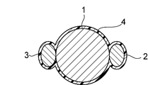
- FIG. 2 is a cross-sectional view taken along the line II-II shown in FIG. 3 is a cross-sectional view taken along line III-III shown in FIG.
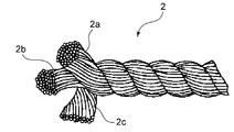
- FIG. 4 is a cross-sectional view showing another example of the sheath yarn in the embodiment of the present invention.
- FIG. 5 is a schematic plan view showing a concrete reinforcing material according to another embodiment of the present invention.
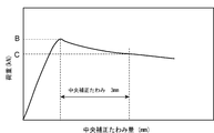
- FIG. 6 is a diagram showing a stress change in a bending test of a concrete molded body.
- FIG. 1 is a schematic plan view showing a concrete reinforcing material according to an embodiment of the present invention.
- FIG. 2 is a cross-sectional view taken along the line II-II shown in FIG. 3 is a cross-sectional view taken along line III-III shown in FIG.
- the concrete reinforcing material 10 of the present embodiment includes one core yarn 1, two sheath yarns 2 and 3 wound around, and a resin layer 4 (illustrated in FIG. 1). (Not shown in FIGS. 2 and 3), and at least one of the core yarn 1 and the two sheath yarns 2 and 3 is made of a glass fiber bundle.
- the reinforcing effect and toughness of the concrete compact using this concrete reinforcing material 10 can be improved.
- at least two sheath yarns 2 and 3 are wound around the core yarn 1 and the glass fiber has a high elastic modulus and a high breaking stress, so that the reinforcing effect of the concrete molded body is sufficient.
- at least two sheath yarns 2 and 3 have sufficient hardness, so that the pull-out resistance after the occurrence of cracks is increased.
- the concrete reinforcing material 10 of the present embodiment has the core yarn 1, the sheath yarns 2 and 3 covered with the resin layer 4 in a state where the sheath yarns 2 and 3 are wound around the core yarn 1.
- the sheath yarn 2 and the sheath yarn 3 are fixed to the surface of the core yarn 1.
- the concrete reinforcing material 10 according to the present embodiment is obtained by immersing the core yarn 1 around which the sheath yarn 2 and the sheath yarn 3 are wound in the resin solution, and then taking out and drying the core yarn 1, the sheath yarn 2 and 3 is coated with a resin layer 4 and solidified. As shown in FIG.
- the sheath yarn 2 is wound around the core yarn 1 by Z-twisting (it is wound around the core yarn 1 in a clockwise direction), and the sheath yarn 3 is wound around the core yarn 1 by S-twisting. Is wound around the core thread 1 counterclockwise.
- the sheath yarn 2 and the sheath yarn 3 intersect at intersections A1 and A2, as shown in FIG.
- the sheath yarn 3 intersects with the sheath yarn 2 so as to overlap.
- a large convex portion is formed on the surface of the core yarn 1.
- a convex portion made of the sheath yarn 2 or the sheath yarn 3 is formed on the surface of the core yarn 1.
- protrusions function as a pulling resistance when a crack occurs in the concrete molded body and the concrete reinforcing material 10 is pulled out from the concrete molded body. Therefore, since these projections are formed, the resistance to pulling out after the occurrence of cracks can be increased, so that the toughness of the concrete molded body is improved.
- the sheath yarn 2 and the sheath yarn 3 overlap each other on the surface of the core yarn 1 at the intersections A1 and A2 where the sheath yarn 2 and the sheath yarn 3 intersect.
- the large convex part protruded rather than the convex part shown in FIG. The presence of this large convex portion can further increase the pull-out resistance after the occurrence of a crack.
- the winding direction of the sheath yarn 2 is opposite to the winding direction of the sheath yarn 3, but the present invention is not limited to this. Even if the sheath yarn 2 and the sheath yarn 3 are wound in the same direction, since the convex portion is formed on the surface of the core yarn 1, the effect of the present invention can be obtained. However, as described above, when at least one winding direction of the sheath yarn is opposite to the winding direction of the other sheath yarn, a large convex portion is easily formed. By forming such a large convex portion, it is possible to further increase the pull-out resistance after the occurrence of a crack.
- one core yarn 1 is used.
- at least one core yarn may be used, and a plurality of core yarns may be used.
- two sheath yarns 2 and 3 are used.
- at least two sheath yarns may be used, and three or more sheath yarns may be used.
- the number of sheath yarns is 2 to 4, it is easy to wind, and it is easy to form convex portions by winding on the surface of the core yarn.
- all of the core yarn 1, the sheath yarn 2, and the sheath yarn 3 are made of glass fiber bundles.
- the core yarn 1, the sheath yarn 2, and the sheath yarn 3 are each composed of a glass fiber bundle in which a plurality of glass fiber filaments are bundled.
- the present invention is not limited to this, and at least one of the core yarn 1, the sheath yarn 2 and the sheath yarn 3 is composed of a glass fiber bundle, and the others are other than the glass fiber bundle.
- the fiber bundle may be comprised.
- fiber bundles other than glass fiber bundles for example, synthetic fiber bundles such as polypropylene, polyethylene, and acrylic, and inorganic fiber bundles such as carbon fiber bundles can be used.
- the core yarn 1 is preferably composed of a glass fiber bundle.
- the elastic modulus and breaking stress of the concrete reinforcing material 10 can be further increased as compared with the case where the core yarn 1 is a synthetic fiber bundle.
- At least one of the sheath yarn 2 and the sheath yarn 3 is composed of a glass fiber bundle.
- all of the core yarn 1, the sheath yarn 2, and the sheath yarn 3 may be composed of glass fiber bundles. Thereby, the reinforcement effect and toughness of a concrete molded object can further be improved.
- one of the two sheath yarns 2 and 3 may be composed of a glass fiber bundle, and the other may be composed of a fiber bundle other than the glass fiber bundle.
- the fiber bundle other than the glass fiber bundle the above-described synthetic fiber bundle or inorganic fiber bundle can be used.
- both of the two sheath yarns 2 and 3 may be comprised from fiber bundles other than a glass fiber bundle. It is preferable that the sheath yarn is composed of a synthetic fiber bundle that is more flexible than the glass fiber bundle because the sheath yarn can be easily wound around the core yarn 1.
- sheath yarns 2 and sheath yarns 3 are fiber bundles in which monofilaments are bundled, when coated with resin, the impregnation of the resin into the fiber bundle is improved, and the core yarns 1 and 2 The adhesive force of the sheath yarns 2 and 3 is increased.
- the monofilament diameter is not particularly limited, but in the case of a glass fiber bundle, the diameter of the glass fiber monofilament is preferably in the range of 12 to 26 ⁇ m suitable for fiber production.
- the core yarn 1 preferably has a thickness (tex) in the range of 100 to 1200 tex. If it is less than 100 tex, the breaking load of the core yarn 1 becomes small, and the reinforcing effect of the concrete molded body may be insufficient. Moreover, since the concrete reinforcing material 10 becomes thin, the volume per concrete reinforcing material becomes small. Therefore, when trying to add the concrete reinforcing material 10 to the concrete at a predetermined ratio (volume%), it is necessary to add a large number of the concrete reinforcing materials 10 and the fluidity tends to be lowered when kneading with the concrete. Become. Moreover, when it exceeds 1200 tex, the volume per concrete reinforcing material will become large.
- the reinforcing effect may be insufficient. More preferably, it is in the range of 130 to 400 tex, and still more preferably in the range of 130 to 350 tex.
- the two sheath yarns 2 and 3 are preferably twisted yarns which are fiber bundles to which twists are added.
- the fiber bundle usually takes a form in which there are no twists in which monofilaments are juxtaposed. Therefore, when an external force is applied to the fiber bundle by the manufacturing process of the concrete reinforcing material 10 or the like, the external shape tends to become a flat shape.
- the cross section of the fiber bundle itself is less likely to be flat even when an external force is applied, and the fiber bundle can be made thicker. Therefore, when the two sheath yarns 2 and 3 are wound around the core yarn 1, a more protruding convex portion can be formed than when a bundle of fibers in a monofilament state in parallel is wound.
- FIG. 4 is a cross-sectional view showing another example of the sheath yarn 2 in the embodiment of the present invention.
- the sheath yarn 2 may be a twisted yarn obtained by twisting twisted yarns 2 a, 2 b, and 2 c obtained by twisting parallel fiber monofilaments.
- the sheath yarn 2 has been described above with reference to FIG. 4, but the same applies to the sheath yarn 3.
- the glass used for the glass fiber monofilament examples include E glass, T glass, S glass, H glass, AR glass, and the like, but AR glass which is an alkali resistant glass containing a large amount of ZrO 2 having particularly excellent alkali resistance. Is preferred.
- AR glass fiber monofilament By using the AR glass fiber monofilament, the concrete reinforcing material 10 is hardly eroded by the alkali component in the concrete, and the concrete reinforcing material 10 is hardly deteriorated.
- the AR glass fiber monofilament is preferably made of glass containing 12 to 24% of ZrO 2 in terms of mass percentage. Since the glass containing 12% or more of ZrO 2 in mass percentage display has good alkali resistance, it is difficult to be eroded by alkali components contained in cement. Moreover, if it is a glass containing a ZrO 2 content of 24% or less in terms of mass percentage, it can be manufactured at a relatively low cost.
- AR glass fibers monofilament, as represented by mass percentage more preferably made of glass containing ZrO 2 14 ⁇ 20%, and further preferably made of glass containing ZrO 2 16 ⁇ 19%.
- the AR glass is, for example, expressed in terms of mass percentage, SiO 2 54 to 65%, ZrO 2 12 to 24%, MgO + CaO 0 to 10%, TiO 2 0 to 10%, Al 2 O 3 0 to 2 %, Glass containing 10-30% of Li 2 O + Na 2 O + K 2 O.
- the sheath yarn 2 preferably has a thickness of 50 to 2000 tex.
- it is less than 50 tex when it is wound around the core yarn 1, the convex portion formed on the surface of the core yarn 1 becomes small, and sufficient pulling resistance may not be obtained.
- it exceeds 2000 tex when knead
- the sheath thread 2 has been described, but the same applies to the sheath thread 3.
- the thickness (tex) of the sheath yarn 2 is preferably in the range of 0.1 to 4 times the thickness (tex) of the core yarn 1. When it is less than 0.1 times, when it is wound around the core yarn 1, the convex portion formed on the surface of the core yarn 1 becomes small, and sufficient pulling resistance may not be obtained. When it exceeds 4 times, the core yarn 1 loses the tension of the sheath yarn when it is wound, and the core yarn may be broken. More preferably, it is in the range of 0.2 to 3 times.
- the sheath thread 2 has been described, but the same applies to the sheath thread 3.
- the thickness (tex) of at least two sheath yarns 2 and 3 may be the same or different.
- the cross-sectional area of the thickest sheath yarn is preferably 0.2 mm 2 or more. Further, when the thickest sheath yarn is a synthetic fiber bundle, the sheath yarn can be easily wound around the core yarn.
- the circumferential pitch (P shown in FIG. 1) in winding the sheath yarn 2 is preferably in the range of 1 to 20 mm.
- the pitch P of the circumference of the sheath yarn 2 is less than 1 mm, the cement component in the concrete is difficult to sufficiently enter between the pitches of the sheath yarn 2, and a sufficient pulling resistance may not be obtained.
- the pitch P of the circumference of the sheath yarn 2 exceeds 20 mm, the convex portions formed on the surface of the core yarn are reduced, and sufficient pulling resistance may not be obtained.
- the pitch P of the circumference of the sheath yarn 2 is more preferably in the range of 4 to 10 mm.
- the sheath thread 2 has been described, but the same applies to the sheath thread 3.
- the concrete reinforcing material 10 of the present invention is preferably made of chopped strands, and the length is preferably in the range of 10 to 40 mm. If it is shorter than 10 mm, sufficient pulling resistance may not be obtained when a crack occurs. Furthermore, when it is going to add the concrete reinforcing material 10 with a predetermined ratio (volume%) with respect to concrete, it is necessary to add many concrete reinforcing materials 10 (chopped strand), and when mixing with concrete, it is fluidity
- the chopped strand is obtained by winding a sheath yarn around a core yarn, coating with a resin, and then cutting.
- the method of winding the two sheath yarns 2 and 3 around the core yarn 1 is not particularly limited, but a method using a covering yarn manufacturing apparatus can be applied.
- the content of the resin 4 covering the core yarn 1 and the two sheath yarns 2 and 3 in the concrete reinforcing material 10 of the present invention is based on the total of the core yarn 1, the two sheath yarns 2 and 3 and the resin 4.
- the content is preferably 5 to 30% by mass. If it is less than 5% by mass, it is difficult to sufficiently bond the core yarn 1 and the two sheath yarns 2 and 3, and the sheath yarn may be peeled off from the core yarn 1 when kneaded with concrete. On the other hand, if it exceeds 30% by mass, the film of the resin 4 becomes thick and the surface tends to be smooth, and it may not be possible to ensure the deformed shape of the convex portion that is effective for pulling resistance.
- the core yarn 1 and the two sheath yarns 2 and 3 are covered with the resin 4, it is preferable that the core yarn 1 and the two sheath yarns 2 and 3 are entirely covered with the resin 4. Without the resin coating, when the core yarn 1 and / or the two sheath yarns 2 and 3 are made of glass fiber bundles, the glass fiber bundles are too good for adhesion to the cement matrix. When this occurs, the glass fiber bundle may be broken. Therefore, coating the core yarn 1 and the two sheath yarns 2 and 3 with the resin 4 prevents the glass fiber bundle from adhering to the cement matrix, and prevents the glass fiber from breaking when a crack occurs. Can be prevented. *
- the type of resin is not particularly limited, but an emulsion type resin is preferably used.
- Thermosetting resins such as polyester and vinyl ester used for FRP products and thermoplastic resins such as polyvinyl chloride, nylon, polypropylene, and polyethylene that can be deformed after molding can be used. It is preferable to apply these resins in an emulsion and dry them.
- the type of emulsion is not particularly limited, such as vinyl acetate type, acrylic type, urethane type, epoxy type, polyester type, polyolefin type, etc., but there is an acrylic type emulsion that is excellent in alkali resistance, inexpensive, and can be adjusted to various hardnesses. Especially suitable.
- water-soluble polymer examples include polyvinyl alcohol, polyvinyl pyrrolidone, polyethylene glycol, and celluloses.
- FIG. 5 is a schematic plan view showing a concrete reinforcing material 20 according to another embodiment of the present invention.
- the concrete reinforcing material 20 of the present embodiment is made of a woven fabric obtained by knitting a core yarn 1 and a covering yarn 5 composed of sheath yarns 2 and 3 wound around the core yarn 1 in a mesh shape.
- the core yarn 1 and the sheath yarns 2 and 3 can be made of the materials and shapes described with reference to FIGS.
- the covering yarns 5 cross each other in a substantially vertical direction and are knitted to form a mesh-like woven fabric.
- the present invention is not limited to this, and the mesh may be formed by crossing each other obliquely and knitting.
- two covering yarns 5 are crossed and knitted to form a mesh.
- three or more covering yarns 5 are crossed and knitted to form a mesh. Good.
- the concrete molded body of the present invention preferably contains 0.3 to 2% by volume of the above-mentioned concrete reinforcing material of the present invention. If the content of the concrete reinforcing material is lower than 0.3% by volume, the concrete reinforcing effect is low, and when the concrete molded body is cracked due to external stress, the concrete may be easily peeled off. is there. Moreover, when higher than 2 volume%, when knead
- Examples of the cement used for the concrete molded body include ordinary Portland cement, blast furnace cement, fly ash cement, and silica cement.
- the cement content in the concrete compact is, for example, preferably 225 kg or more (hereinafter referred to as kg / m 3 ) in terms of mass per 1 m 3 of concrete.
- the fine aggregate such as river sand in the concrete molded body is preferably 1500 kg / m 3 or less, and the coarse aggregate such as river gravel is preferably 1500 kg / m 3 or less.
- These materials are kneaded by adding water or an admixture to such an extent that separation does not occur, and then a concrete reinforcing material cut to a predetermined length is added to 0.3 to 2% by volume. Concrete can be produced by kneading until the material is uniform, poured into a mold so as to have a desired shape, and after curing, the mold is removed to obtain a concrete compact.
- the concrete reinforcing material made of a woven fabric shown in FIG. 5 can be used, for example, disposed in the vicinity of the concrete surface. Specifically, for example, after pouring concrete, a concrete reinforcing material made of woven fabric can be arranged and used on the concrete.
- the concrete reinforcing material 10 of the embodiment shown in FIG. 1 was produced as follows.
- a glass fiber strand (DWR) having a thickness of 1100 tex was used.
- glass fiber twisted yarn (a twisted yarn product ACK371 / 3 2.2S TF-126 in which three 0.7Z twisted glass yarns of K37 were twisted in 2.2S) was used. Therefore, the sheath yarns 2 and 3 have a structure in which three glass fiber bundles 2a, 2b and 2c are twisted to form a twisted yarn as shown in FIG.
- the thicknesses of the sheath yarns 2 and 3 are both 465 tex.
- the glass fiber monofilament constituting the core yarn 1, sheath yarn 2 and sheath yarn 3 is SiO 2 57.7%, ZrO 2 17.5%, Na 2 O 15.7%, TiO 2 7.4% by mass. , CaO 1.2%, Al 2 O 3 0.2%, K 2 O 0.2%, Li 2 O 0.1%.
- a polyolefin sizing agent was used for the glass fiber strand, and a starch sizing agent was used for the glass fiber twisted yarn.
- the pitch P of the circumference of the sheath yarns 2 and 3 was adjusted by controlling the passing speed of the core yarn 1 in the covering yarn device and the number of windings of the sheath yarns 2 and 3. In this example, the pitch P of the circumference of the sheath yarns 2 and 3 was adjusted to 6 mm.
- the core yarn 1 wound with the sheath yarn 2 and the sheath yarn 3 is immersed in an acrylic emulsion solution adjusted to a predetermined concentration, and dried with a hot roller set at 130 ° C.
- the sheath yarn 2 and the sheath yarn 3 were fixed with an acrylic resin to prepare a precursor.
- the resin content was 15% by mass.
- this precursor was cut into a length of 30 mm using a cutter machine to obtain a concrete reinforcing material of this example made of chopped strands.
- Example 2 A concrete reinforcing material was prepared in the same manner as in Example 1 except that the pitch P of the circumference of the sheath yarns 2 and 3 was adjusted to 12 mm, and the resin content was 13% by mass. A concrete molded body was produced by using this.
- Example 3 A concrete reinforcing material is produced in the same manner as in Example 1 except that a glass fiber strand (DWR) having a thickness of 310 tex is used as the core yarn 1 and the pitch P of the circumference of the sheath yarns 2 and 3 is adjusted to 4 mm. Then, a concrete molded body was produced using this concrete reinforcing material.
- DWR glass fiber strand
- Example 4 As the sheath yarns 2 and 3, glass fiber strands (DWR) having a thickness of 620 tex are used, the pitch P of the circumference of the sheath yarns 2 and 3 is adjusted to 8 mm, and the resin content is 16% by mass, except for the above.
- a concrete reinforcement was produced in the same manner as in Example 3, and a concrete molded body was produced using this concrete reinforcement.
- Example 5 As the sheath yarns 2 and 3, using glass fiber twisted yarn having a thickness of 930 tex, the pitch P of the circumference of the sheath yarns 2 and 3 is adjusted to 16 mm, and the content of the resin is 18% by mass. A concrete reinforcement was produced in the same manner as in Example 1, and a concrete molded body was produced using this concrete reinforcement.
- Example 6 A concrete reinforcing material was prepared in the same manner as in Example 5 except that the pitch P of the circumference of the sheath yarns 2 and 3 was adjusted to 6 mm, and the resin content was 17% by mass. A concrete molded body was produced by using this.
- Example 7 As the core yarn 1, a glass fiber yarn having a thickness of 155 tex (one 0.7Z twist of K37) is used, and as the sheath yarns 2 and 3, a glass fiber strand (DWR) having a thickness of 310 tex is used, and the sheath yarns 2 and 3 are used.
- a concrete reinforcing material was prepared in the same manner as in Example 1 except that the pitch P of one circle was adjusted to 8 mm, and a concrete molded body was prepared using this concrete reinforcing material.
- Example 8 A glass fiber strand (DWR) having a thickness of 310 tex is used as the core yarn 1, a DWR having a thickness of 1100 tex is used as the sheath yarns 2 and 3, and the pitch P of the circumference of the sheath yarns 2 and 3 is adjusted to 10 mm.
- a concrete reinforcing material was produced in the same manner as in Example 1 except that the content of was 12% by mass, and a concrete molded body was produced using this concrete reinforcing material.
- Example 9 The core yarn 1 is a glass fiber strand (DWR) having a thickness of 310 tex, the sheath yarns 2 and 3 are a vinylon fiber twisted yarn having a thickness of 200 tex, and the resin content is 13% by mass, except for the above.
- a concrete reinforcement was produced in the same manner as in Example 1, and a concrete molded body was produced using the concrete reinforcement.
- Example 10 A glass fiber yarn having a thickness of 155 tex (one KZ 0.7Z twist) is used as the core yarn 1, and a glass fiber yarn having a thickness of 155 tex (one KZ 0.7Z twist) is used as the sheath yarn 2.
- a concrete reinforcing material is produced in the same manner as in Example 1 except that a vinyl tex fiber twisted yarn having a thickness of 600 tex is used as the sheath yarn 3, the resin content is 12% by mass, and the pitch P is 5 mm. Then, a concrete molded body was produced using this concrete reinforcing material.
- Example 11 A glass fiber yarn having a thickness of 155 tex (one KZ 0.7Z twist) is used as the core yarn 1, and a glass fiber yarn having a thickness of 155 tex (one KZ 0.7Z twist) is used as the sheath yarn 2.
- a concrete reinforcing material is produced in the same manner as in Example 1 except that a PP fiber twisted yarn having a thickness of 390 tex is used as the sheath yarn 3, the resin content is 14% by mass, and the pitch P is 6 mm. Then, a concrete molded body was produced using this concrete reinforcing material.
- Example 1 As the core yarn 1, a glass fiber twisted yarn having a thickness of 1100 tex is used, and without using the sheath yarns 2 and 3, only the core yarn 1 is used as a concrete reinforcing material. A molded body was produced. In addition, as the core yarn 1, the same glass fiber twisted yarn as in Example 1 was used.
- Comparative Example 2 A concrete molded body was produced in the same manner as in Comparative Example 1 except that a polypropylene (PP) fiber strand having a thickness of 1000 tex with no resin coating was used as the core yarn 1.
- PP polypropylene
- Comparative Example 3 A concrete molded body was produced in the same manner as in Comparative Example 2 except that a concrete reinforcing material using a steel fiber having a length of 50 mm was added as the core yarn 1 so as to be 0.5% by volume.
- the fluidity of the concrete was evaluated using the slump value.
- the slump value was measured in accordance with a concrete slump test method shown in JIS A 1101 (2014) by sampling a part of the concrete.
- liquidity of concrete is excellent and a moldability improves, so that a slump value is large.
- FIG. 6 is a diagram showing a stress change in a bending test of a concrete molded body.
- the reinforcing effect of the concrete molded body was evaluated by the maximum load value B (load value at the time of crack occurrence) shown in FIG.
- the toughness of the concrete molded body is determined by measuring the load width C when the amount of deflection after crack generation is 3 mm, that is, the opening width of the crack with a 150 mm pie-type displacement meter attached to the bottom of the center of the concrete molded body.
- the load value when the amount of deflection after the crack generation (center corrected deflection amount) corresponding to 3/4 times the opening width of the crack was 3 mm was measured and evaluated.
- Table 1 shows the measurement results of the slump value, the maximum load value B, and the load value C with a center correction deflection of 3 mm in Examples 1 to 11 and Comparative Examples 1 to 3.
- Examples 1 to 11 according to the present invention have a high slump value and excellent fluidity of the concrete. Further, when the concrete reinforcing materials of Examples 1 to 11 according to the present invention are used, the concrete molded body has a high maximum load value B and a load value C at a center correction deflection of 3 mm, and the reinforcing effect of the concrete molded body is high. It can be seen that the toughness can be improved.
- Comparative Examples 1 to 3 did not have a sheath thread, the maximum load value B of the concrete molded body and the load value C with a center correction deflection of 3 mm were both low. Moreover, since the comparative example 3 uses the steel fiber, the slump value was low.
Landscapes
- Engineering & Computer Science (AREA)
- Chemical & Material Sciences (AREA)
- Ceramic Engineering (AREA)
- Structural Engineering (AREA)
- Materials Engineering (AREA)
- Organic Chemistry (AREA)
- Mechanical Engineering (AREA)
- Textile Engineering (AREA)
- Inorganic Chemistry (AREA)
- Chemical Kinetics & Catalysis (AREA)
- Civil Engineering (AREA)
- Yarns And Mechanical Finishing Of Yarns Or Ropes (AREA)
- Curing Cements, Concrete, And Artificial Stone (AREA)
- Woven Fabrics (AREA)
Abstract
コンクリート成形体の補強効果及び靱性を向上させることができ、かつ成形性が良好なコンクリート補強材及びそれを含有するコンクリート成形体を提供する。 少なくとも1本の芯糸1と、芯糸1に巻き付くように構成された少なくとも2本の鞘糸2,3と、芯糸1及び鞘糸2,3を被覆する樹脂層とを含むコンクリート補強材10であって、芯糸1及び鞘糸2,3のうちの少なくとも1本が、ガラス繊維束から構成されていることを特徴としている。
Description
本発明は、コンクリート補強材及びそれを含むコンクリート成形体に関する。
従来、コンクリート成形体は、構造体として種々の用途に用いられている。特に、トンネルの内壁や高架壁では、剥落防止のため、補強材としてポリプロピレン、ポリエチレン、アクリルなどの合成繊維束を用いたコンクリート成形体が使用されている。このようなコンクリート成形体は、クラック発生後も、補強材が切断されずに、補強材の引き抜け抑制効果により、コンクリートが割れにくく、剥落しにくくなる。
しかし、ポリプロピレンなどの合成繊維束は、弾性率や破断応力が低いため、コンクリートの補強材として用いた場合、コンクリート成形体の補強効果や靭性が十分でないという問題がある。
また、補強材としてスチールファイバも使用されているが、スチールファイバは、錆が発生しやすいことや、コンクリートと混練する際に、流動性が低下し、コンクリート成形体の成形性が低下しやすいという問題がある。
これらの問題を解決できる補強材として、ガラス繊維を樹脂で被覆した補強材が挙げられる。ガラス繊維は、合成繊維よりも弾性率や破断応力が高く、錆びることがなく、コンクリート混練時の成形性に優れている。しかし、ガラス繊維を樹脂で被覆した補強材は、クラック発生後の引抜け抵抗力が低いため、コンクリート成形体の靱性が低い。
これに対し、連続した無機繊維束に樹脂を含浸させ、それを硬化させてから切断し、表面に凹凸を形成したコンクリート補強材が提案されている(特許文献1)。
上記特許文献1のコンクリート補強材は、ガラス繊維束などの無機繊維束を用いているので、弾性率が高く、錆びないため、コンクリート成形体の補強効果を向上させることができる。また、表面に凹凸が形成されているので、クラック発生後の引き抜けの抵抗力を高めることができるため、コンクリート成形体の靱性が高い。
しかしながら、トンネルの内壁や高架壁等において、剥落防止効果の向上のため、コンクリート成形体の靱性をさらに高めることができるコンクリート補強材が求められている。しかし、含浸した樹脂をプレスや歯車等によって形成した凹凸は柔らかいため、クラック発生後の引き抜けの抵抗力を十分に高めることができない。
本発明の目的は、コンクリート成形体の補強効果及び靱性を向上させることができ、かつ成形性が良好なコンクリート補強材及びそれを含有するコンクリート成形体を提供することにある。
本発明のコンクリート補強材は、少なくとも1本の芯糸と、芯糸に巻き付けられた少なくとも2本の鞘糸と、芯糸及び/または鞘糸を被覆した樹脂層とを含むコンクリート補強材であって、芯糸及び鞘糸のうちの少なくとも1本が、ガラス繊維束から構成されていることを特徴としている。
本発明において、少なくとも1本の鞘糸の巻き付け方向が、他の鞘糸の巻き付け方向と反対であることが好ましい。
本発明において、少なくとも1本の前記芯糸が、ガラス繊維束から構成されていることが好ましい。
本発明において、少なくとも1本の鞘糸は、ガラス繊維束から構成されていることが好ましい。
本発明において、ガラス繊維束から構成されている鞘糸以外の、少なくとも1本の鞘糸は、合成繊維束から構成されていてもよい。
本発明において、芯糸及び鞘糸の全てが、ガラス繊維束から構成されていることがさらに好ましい。
本発明において、少なくとも1本の鞘糸は、撚りが加えられた繊維束から構成されていることが好ましい。
本発明において、芯糸の1本の太さ(tex)が、100~1200texの範囲内であることが好ましい。
本発明において、鞘糸の1本の太さ(tex)は、芯糸の1本の太さ(tex)の0.1倍~4倍の範囲内であることが好ましい。
本発明において、上記少なくとも2本の鞘糸は、それぞれ太さ(tex)が異なっていてもよい。
鞘糸の巻き付けにおける一周のピッチは、1~20mmの範囲内であることが好ましい。
本発明のコンクリート補強材は、チョップドストランドからなることが好ましい。また、チョップドストランドは、10~40mmの範囲内の長さであることが好ましい。
本発明のコンクリート補強材は、少なくとも1本の芯糸と、芯糸に巻き付けられた少なくとも2本の鞘糸と、芯糸及び/または鞘糸を被覆した樹脂層とを含み、芯糸及び鞘糸のうちの少なくとも1本が、ガラス繊維束から構成されているカバーリング糸を、メッシュ状に配置させた織物からなるものであってもよい。
本発明のコンクリート成形体は、上記本発明のコンクリート補強材を含むことを特徴としている。
本発明のコンクリート成形体は、コンクリート補強材を、0.3~2.0体積%含むことが好ましい。
本発明によれば、コンクリート成形体の補強効果及び靱性を向上させることができ、かつ成形性が良好となる。
以下、好ましい実施形態について説明する。但し、以下の実施形態は単なる例示であり、本発明は以下の実施形態に限定されるものではない。また、各図面において、実質的に同一の機能を有する部材は同一の符号で参照する場合がある。
図1は、本発明の実施形態のコンクリート補強材を示す模式的平面図である。図2は、図1に示すII-II線に沿う断面図である。図3は、図1に示すIII-III線に沿う断面図である。図1~図3に示すように、本実施形態のコンクリート補強材10は、1本の芯糸1と、巻き付けられた2本の鞘糸2,3と、樹脂層4(図1においては図示省略、図2及び図3に図示)により構成されており、芯糸1及び2本の鞘糸2,3のうちの少なくとも1本がガラス繊維束から構成されている。
このため、このコンクリート補強材10を用いたコンクリート成形体の補強効果及び靱性を向上させることができる。これは、少なくとも2本の鞘糸2,3が芯糸1に巻き付けられており、かつ、ガラス繊維が高弾性率と高い破断応力を有しているため、コンクリート成形体の補強効果が十分となり、少なくとも2本の鞘糸2,3は、十分な硬さを有するため、クラック発生後の引抜け抵抗力が高くなるからである。
本実施形態のコンクリート補強材10は、図1~図3に示すように芯糸1に鞘糸2及び3を巻き付けた状態で、芯糸1、鞘糸2及び3が樹脂層4で被覆されて、鞘糸2及び鞘糸3が芯糸1の表面に固着している。本実施形態に係るコンクリート補強材10は、表面に鞘糸2及び鞘糸3を巻き付けた芯糸1を樹脂溶液中に浸漬させ、その後取り出して乾燥させることによって、芯糸1、鞘糸2及び3の表面を樹脂層4で被覆し、固化させて作製される。図1に示すように、鞘糸2は、Z撚りで芯糸1に巻き付けられており(時計回りで芯糸1に巻き付けられており)、鞘糸3は、S撚りで芯糸1に巻き付けられている(反時計回りで芯糸1に巻き付けられている)。このように、鞘糸2の巻き付け方向が、鞘糸3の巻き付け方向と反対であることにより、図1に示すように、鞘糸2と鞘糸3が交差点A1及びA2で交差する。
図2に示すように、本実施形態では、交差点A1において、鞘糸2の上に鞘糸3が重なるように交差している。鞘糸2の上に鞘糸3が重なることにより、芯糸1の表面上に大きな凸部が形成される。
図3に示すように、本実施形態では、芯糸1の表面に、鞘糸2または鞘糸3からなる凸部が形成される。
これらの凸部は、コンクリート成形体にクラックが発生し、コンクリート補強材10がコンクリート成形体から引き抜かれる際に、引き抜きの抵抗として機能する。したがって、これらの凸部が形成されることより、クラック発生後の引き抜けの抵抗力を高めることができるため、コンクリート成形体の靱性が向上する。
本実施形態では、図2を参照して説明したように、鞘糸2と鞘糸3が交差する交差点A1及びA2において、芯糸1の表面に、鞘糸2と鞘糸3が重なり合って形成された大きな凸部は、図3に示す凸部よりも突出している。この大きな凸部の存在により、クラック発生後の引き抜けの抵抗力をさらに高めることができる。
本実施形態では、鞘糸2の巻き付け方向が、鞘糸3の巻き付け方向と反対であるが、本発明はこれに限定されるものではない。鞘糸2と鞘糸3が同じ方向に巻き付けられても、芯糸1の表面に凸部が形成されるので、本発明の効果を得ることができる。しかしながら、上述のように、鞘糸の少なくとも1本の巻き付け方向が、他の鞘糸の巻き付け方向と反対方向とすることにより、大きな凸部が形成されやすい。このような大きな凸部が形成されることにより、クラック発生後の引き抜けの抵抗力をさらに高めることができる。
本実施形態では、芯糸1を1本用いているが、本発明では、少なくとも1本の芯糸を用いればよく、複数本の芯糸を用いてもよい。本実施形態では、鞘糸2,3を2本用いているが、本発明では、少なくとも2本の鞘糸を用いればよく、3本以上の鞘糸を用いてもよい。鞘糸は、2~4本であると、巻き付け加工がしやすく、芯糸の表面に巻き付けによる凸部を形成しやすい。
本実施形態では、芯糸1、鞘糸2及び鞘糸3のいずれもが、ガラス繊維束から構成されている。具体的には、芯糸1、鞘糸2及び鞘糸3は、それぞれ複数のガラス繊維フィラメントを束ねたガラス繊維束から構成されている。しかしながら、本発明は、これに限定されるものではなく、芯糸1、鞘糸2及び鞘糸3のうちの少なくとも1本が、ガラス繊維束から構成されており、それ以外はガラス繊維束以外の繊維束から構成されていてもよい。芯糸1、鞘糸2及び鞘糸3のうちの少なくとも1本がガラス繊維束から構成されることにより、コンクリート成形体の補強効果を向上させることができる。ガラス繊維束以外の繊維束としては、例えば、ポリプロピレン、ポリエチレン、アクリルなどの合成繊維束や、炭素繊維束などの無機繊維束を用いることができる。
なお、コンクリート補強材10がガラス繊維束と、ガラス繊維束以外の繊維束から構成されている場合において、芯糸1は、ガラス繊維束から構成されていることが好ましい。芯糸1がガラス繊維束であると、芯糸1が合成繊維束である場合と比較して、コンクリート補強材10の弾性率や破断応力を更に高めることができる。
本発明において、鞘糸2及び鞘糸3の少なくとも1本がガラス繊維束から構成されていることが好ましい。これにより、クラック発生後の引き抜けの抵抗力をさらに高めるができ、コンクリート成形体の補強効果を向上させることができる。本発明においては、本実施形態のように、芯糸1、鞘糸2及び鞘糸3の全てがガラス繊維束から構成されてもよい。これにより、コンクリート成形体の補強効果及び靱性をさらに向上させることができる。
本発明において、2本の鞘糸2,3のいずれか一方は、ガラス繊維束から構成され、他方はガラス繊維束以外の繊維束から構成されていてもよい。このような構成であれば、芯糸1を100~160tex程度まで細くしても、コンクリート成形体の補強効果を担保することができる。この場合、ガラス繊維束以外の繊維束としては、上述の合成繊維束や、無機繊維束を用いることができる。また、本発明において、2本の鞘糸2,3のいずれもが、ガラス繊維束以外の繊維束から構成されていてもよい。鞘糸が、ガラス繊維束より柔軟である合成繊維束から構成されていると、芯糸1に鞘糸を巻き付けやすくなるため好ましい。
全ての芯糸1、鞘糸2及び鞘糸3がモノフィラメントを束ねた繊維束である場合、樹脂で被覆する際、繊維束への樹脂の含浸性が良くなり、芯糸1、と2本の鞘糸2,3の接着力が大きくなる。モノフィラメント径は、特に制限されないが、ガラス繊維束の場合、ガラス繊維モノフィラメントの径は、繊維の製造に適した12~26μmの範囲内であると好ましい。
芯糸1は、1本の太さ(tex)が、100~1200texの範囲内であることが好ましい。100tex未満であると、芯糸1の破断荷重が小さくなり、コンクリート成形体の補強効果が不十分となる場合がある。また、コンクリート補強材10が細くなるため、コンクリート補強材1本あたりの体積が小さくなる。そのため、コンクリートに対してコンクリート補強材10を所定割合(体積%)添加しようとする場合、多本数のコンクリート補強材10を添加する必要があり、コンクリートと混練する際に、流動性が低下しやすくなる。また、1200texを超えると、コンクリート補強材1本あたりの体積が大きくなる。そのため、コンクリートに対してコンクリート補強材10を所定割合(体積%)添加しようとする場合、少数本のコンクリート補強材10しか添加できず、コンクリートとコンクリート補強材10の接触面積が低下し、コンクリートの補強効果が不十分となる場合がある。より好ましくは、130~400texの範囲内であり、更に好ましくは、130~350texの範囲内である。
また、2本の鞘糸2,3は、撚りが加えられた繊維束である撚り糸であることが好ましい。繊維束は、通常モノフィラメントが並列した撚りがない形態をとっている。そのため、コンクリート補強材10の製造工程等によって、繊維束に外力が加わると、その外力によって扁平形状となりやすい。この並列したモノフィラメントに撚りを加え、並列したモノフィラメントが撚れることで、外力が加わっても繊維束自体の断面が扁平形状となりにくく、繊維束に、より厚みを持たせることができる。そのため2本の鞘糸2,3を芯糸1に巻き付ける際に、並列したモノフィラメント状態となっている繊維束を巻き付けた時よりも、より突出した凸部を形成することができる。
図4は、本発明の実施形態における鞘糸2の他の例を示す断面図である。図4に示すように、鞘糸2は、並列した繊維モノフィラメントに撚りが加えられた撚り糸2a、2b及び2cを撚り合わせた合撚糸であってもよい。
以上、図4を参照して、鞘糸2について説明したが、鞘糸3についても同様である。
ガラス繊維モノフィラメントに用いられるガラスの種類としては、Eガラス、Tガラス、Sガラス、Hガラス、ARガラス等が挙げられるが、特に耐アルカリ性に優れたZrO2を多く含む耐アルカリ性ガラスであるARガラスが好ましい。ARガラス繊維モノフィラメントを用いることにより、コンクリート補強材10が、コンクリート中のアルカリ成分によって浸食されにくくなり、コンクリート補強材10の劣化が生じにくくなる。
ARガラス繊維モノフィラメントは、質量百分率表示で、ZrO2を12~24%含有するガラスからなることが好ましい。質量百分率表示で、ZrO2を12%以上含有するガラスは、耐アルカリ性が良好であるため、セメントに含まれるアルカリ成分により浸食されにくい。また、質量百分率表示で、ZrO2を24%以下含有するガラスであれば、比較的安価なコストで製造することができる。なお、ARガラス繊維モノフィラメントは、質量百分率表示で、ZrO2を14~20%含有するガラスからなることがより好ましく、ZrO2を16~19%含有するガラスからなることが更に好ましい。
ARガラスは、例えば、質量百分率表示で、SiO2を54~65%、ZrO2を12~24%、MgO+CaOを0~10%、TiO2を0~10%、Al2O3を0~2%、Li2O+Na2O+K2Oを10~30%含有するガラスが挙げられる。
鞘糸2は1本の太さが、50~2000texであることが好ましい。50tex未満であると、芯糸1に巻き付けた際に、芯糸1の表面に形成される凸部が小さくなり、十分な引き抜き抵抗力が得られない場合がある。また、2000texを超えると、コンクリートと混練する際に、芯糸1の表面に形成される凸部でコンクリートとの抵抗が大きくなりすぎ、流動性が低下する場合がある。50~2000texの範囲であると、引き抜き抵抗力と流動性を確保しやすい。より好ましくは、200~1500texである。なお、鞘糸2について説明したが、鞘糸3についても同様である。
鞘糸2の1本の太さ(tex)は、芯糸1の1本の太さ(tex)の0.1倍~4倍の範囲内であることが好ましい。0.1倍未満であると、芯糸1に巻き付けた際に、芯糸1の表面に形成される凸部が小さくなり、十分な引き抜き抵抗力が得られない場合がある。4倍を超えると、巻き付ける際に芯糸1が鞘糸の張力に負けてしまい、芯糸が切れてしまう場合がある。より好ましくは、0.2倍~3倍の範囲内である。なお、鞘糸2について説明したが、鞘糸3についても同様である。
少なくとも2本の鞘糸2,3の太さ(tex)は、同一であっても異なっていてもよい。例えば、最も太い鞘糸の太さ(tex)と最も細い鞘糸の太さ(tex)の比は、最も太い鞘糸の太さ(tex):最も細い鞘糸の太さ(tex)=5:1~20:1であれば、芯糸1の表面に十分な大きさの凸部を形成でき、ストランドを細くすることが可能である。最も太い鞘糸の断面積は0.2mm2以上であることが好ましい。また、最も太い鞘糸が合成繊維束であると、鞘糸を芯糸に巻き付けやすくなる。
鞘糸2の巻き付けにおける一周のピッチ(図1に示すP)は、1~20mmの範囲内であるであることが好ましい。鞘糸2の一周のピッチPが、1mm未満であると、コンクリート中のセメント成分が十分に鞘糸2のピッチ間に入っていきにくくなり、十分な引き抜き抵抗力を得られない場合がある。また、鞘糸2の一周のピッチPが、20mmを超えると、芯糸の表面に形成される凸部が少なくなり、十分な引き抜き抵抗力が得られない場合がある。鞘糸2の一周のピッチPは、より好ましくは、4~10mmの範囲内である。なお、鞘糸2について説明したが、鞘糸3についても同様である。
本発明のコンクリート補強材10は、チョップドストランドからなることが好ましく、長さは、10~40mmの範囲内であることが好ましい。10mmより短いと、クラックが発生した際に十分な引き抜き抵抗が得られない場合がある。さらに、コンクリートに対してコンクリート補強材10を所定割合(体積%)添加しようとする場合、多本数のコンクリート補強材10(チョップドストランド)を添加する必要があり、コンクリートと混練する際に、流動性が低下しやすくなる。また、40mmより長いと、コンクリートとの混練時に、コンクリートの流動性が著しく低下し、作業性が悪化する場合がある。またコンクリート補強材10同士が絡まり、コンクリート中で均一に分散できないため好ましくない。チョップドストランドは、芯糸に鞘糸を巻き付け、樹脂で被覆した後に切断することにより得られる。
芯糸1への2本の鞘糸2,3の巻き付け方法は、特に限定されないが、カバーリングヤーンの製造装置を用いた方法などが適用できる。
本発明のコンクリート補強材10における芯糸1と2本の鞘糸2,3を被覆した樹脂4の含有量は、芯糸1、2本の鞘糸2,3及び樹脂4の合計に対して5~30質量%であることが好ましい。5質量%未満であると、十分に芯糸1と2本の鞘糸2,3を接着させることが難しく、コンクリートと混練した際に、鞘糸が芯糸1から剥がれてしまう場合がある。また、30質量%を超えると、樹脂4の皮膜が厚くなり、表面が平滑になりやすくなり、引き抜き抵抗性に効果のある凸部の異形性が確保できない場合がある。
芯糸1と2本の鞘糸2,3を樹脂4で被覆する際、芯糸1及び2本の鞘糸2,3全体を樹脂4で被覆することが好ましい。樹脂被覆が無いと、芯糸1及び/または2本の鞘糸2,3がガラス繊維束から構成されている場合、ガラス繊維束はセメントマトリクスと接着性が良すぎるため、セメント成形体にクラックが生じた際に、ガラス繊維束が破断してしまうおそれがある。そのため、芯糸1及び2本の鞘糸2,3全体を樹脂4で被覆することにより、ガラス繊維束とセメントマトリクスとの接着を防止し、クラックが生じた際にガラス繊維が破断するのを防止することができる。
樹脂の種類については特に限定されないが、エマルジョンタイプの樹脂が好ましく用いられる。FRP製品に使用されるポリエステル、ビニルエステル等の熱硬化性樹脂や、成形後に変形可能なポリ塩化ビニル、ナイロン、ポリプロピレン、ポリエチレン等の熱可塑性樹脂が使用可能であるが、ガラス繊維束へ含浸性しやすく、加工しやすいので、これらの樹脂をエマルジョンにして塗布、乾燥させることが好ましい。エマルジョンの種類としては、酢酸ビニル系、アクリル系、ウレタン系、エポキシ系、ポリエステル系、ポリオレフィン系など特に限定されないが、耐アルカリ性に優れ、安価であり、様々な硬さに調整できるアクリル系エマルジョンが特に適している。
また、セメントマトリクスとの親和性を向上させ、コンクリート成形体の機械的強度を向上させるために、上記の樹脂に水溶性高分子を添加することが好ましい。水溶性高分子としては、ポリビニルアルコール、ポリビニルピロリドン、ポリエチレングリコール、セルロース類等が挙げられる。
図5は、本発明の他の実施形態のコンクリート補強材20を示す模式的平面図である。図5に示すように、本実施形態のコンクリート補強材20は、芯糸1と、それに巻き付けられた鞘糸2及び3からなるカバーリング糸5を、メッシュ状に編んだ織物からなる。芯糸1及び鞘糸2及び3は、図1~4等を用いて説明したような材質及び形状とすることができる。本実施形態では、カバーリング糸5を互いに略垂直方向に交差させて、編み込むことによりメッシュ状の織物にしている。しかしながら、本発明は、これに限定されるものではなく、互いに斜めに交差させて、編み込むことによりメッシュ状にしてもよい。また、本実施形態では、2本のカバーリング糸5を交差させて、編み込むことによりメッシュ状にしているが、3本以上のカバーリング糸5を交差させて、編み込むことによりメッシュ状にしてもよい。
本発明のコンクリート成形体は、上述した本発明のコンクリート補強材を0.3~2体積%含有することが好ましい。コンクリート補強材の含有率が0.3体積%よりも低いと、コンクリートの補強効果が低く、外部からの応力によりコンクリート成形体にクラックが発生した際に、コンクリートの剥落が発生しやすくなる場合がある。また、2体積%よりも高いと、コンクリートと混練する際に、コンクリートの流動性が悪くなり、混練作業が困難になり好ましくない。
コンクリート成形体に用いるセメントとしては、例えば、普通ポルトランドセメント、高炉セメント、フライアッシュセメント、シリカセメント等が挙げられる。コンクリート成形体におけるセメントの含有量は、例えば、コンクリート1m3あたりの質量で225kg以上(以後kg/m3と表す)であることが好ましい。コンクリート成形体における川砂等の細骨材は1500kg/m3以下、川砂利等の粗骨材は1500kg/m3以下であることが好ましい。これらの材料を分離が生じない程度に水や混和剤を添加して混練し、次いで所定の長さにカットされたコンクリート補強材を0.3~2体積%になるよう添加後、さらに上記の材料が均一になるまで混練してコンクリートを作製し、所望の形状になるように、型に流し込み、硬化後型を外してコンクリート成形体を得ることができる。
図5に示す織物からなるコンクリート補強材は、例えば、コンクリートの表面近傍に配置して用いることができる。具体的には、例えば、コンクリートを流し込んだ後、その上に織物からなるコンクリート補強材を配置して用いることができる。
(実施例1)
<コンクリート補強材の作製>
図1に示す実施形態のコンクリート補強材10を、以下のようにして作製した。芯糸1として、太さ1100texのガラス繊維ストランド(DWR)を用いた。鞘糸2及び3としては、ガラス繊維合撚糸(K37の0.7Z撚りガラスヤーン3本を2.2Sに合撚した合撚糸品 ACK371/3 2.2S TF-126)を用いた。したがって、鞘糸2及び3は、図4に示すような3本のガラス繊維束2a、2b及び2cを撚り合わせて撚り糸とした構造となっている。鞘糸2及び3の太さは、いずれも465texである。
<コンクリート補強材の作製>
図1に示す実施形態のコンクリート補強材10を、以下のようにして作製した。芯糸1として、太さ1100texのガラス繊維ストランド(DWR)を用いた。鞘糸2及び3としては、ガラス繊維合撚糸(K37の0.7Z撚りガラスヤーン3本を2.2Sに合撚した合撚糸品 ACK371/3 2.2S TF-126)を用いた。したがって、鞘糸2及び3は、図4に示すような3本のガラス繊維束2a、2b及び2cを撚り合わせて撚り糸とした構造となっている。鞘糸2及び3の太さは、いずれも465texである。
芯糸1、鞘糸2及び鞘糸3を構成するガラス繊維モノフィラメントは、質量%でSiO2 57.7%、ZrO2 17.5%、Na2O 15.7%、TiO2 7.4%、CaO 1.2%、Al2O3 0.2%、K2O 0.2%、Li2O 0.1%含有するガラスからなる。なお、ガラス繊維フィラメントの集束剤としては、ガラス繊維ストランドについてはポリオレフィン系の集束剤を用い、ガラス繊維合撚糸についてはでんぷん系の集束剤を用いた。
次に、カバーリングヤーン製造装置を用いて、芯糸1に、鞘糸2及び3をそれぞれ反対方向に巻き付けた。鞘糸2及び3の一周のピッチPは、芯糸1のカバーリングヤーン装置内の通過速度と鞘糸2及び3の巻き付け回数を制御することによって調整した。本実施例では、鞘糸2及び3の一周のピッチPを、6mmに調整した。
次に、鞘糸2及び鞘糸3を巻き付けた芯糸1を所定の濃度に調整したアクリルエマルジョン溶液に浸漬し、130℃に設定したホットローラーにて乾燥することにより、芯糸1の表面に、鞘糸2及び鞘糸3をアクリル樹脂で固着させ、前駆体を作製した。樹脂の含有量は、15質量%であった。
次に、この前駆体を、カッターマシンを用いて、長さ30mmに切断し、チョップドストランドからなる本実施例のコンクリート補強材を得た。
<コンクリート成形体の作製>
普通ポルトランドセメントを363kg/m3、最大粒径5.0mmの川砂(細骨材)を859kg/m3、最大粒径25mmの川砂利(粗骨材)を806kg/m3、水を161kg/m3、及び高性能AE減水剤(株式会社エヌエムビー製:商品名レオビルドSP-8N)を4.7kg/m3の比率で混練し、次いで上記のコンクリート補強材を1体積%になるように添加した。その後、30秒間混練してコンクリートを作製した。このコンクリートを15cm×15cm×60cmの型枠に流し込み、16時間後脱型してコンクリート成形体を得た。
普通ポルトランドセメントを363kg/m3、最大粒径5.0mmの川砂(細骨材)を859kg/m3、最大粒径25mmの川砂利(粗骨材)を806kg/m3、水を161kg/m3、及び高性能AE減水剤(株式会社エヌエムビー製:商品名レオビルドSP-8N)を4.7kg/m3の比率で混練し、次いで上記のコンクリート補強材を1体積%になるように添加した。その後、30秒間混練してコンクリートを作製した。このコンクリートを15cm×15cm×60cmの型枠に流し込み、16時間後脱型してコンクリート成形体を得た。
(実施例2)
鞘糸2及び3の一周のピッチPを12mmに調整し、樹脂の含有量が13質量%であること以外、上記の実施例1と同様にしてコンクリート補強材を作製し、このコンクリート補強材を用いてコンクリート成形体を作製した。
鞘糸2及び3の一周のピッチPを12mmに調整し、樹脂の含有量が13質量%であること以外、上記の実施例1と同様にしてコンクリート補強材を作製し、このコンクリート補強材を用いてコンクリート成形体を作製した。
(実施例3)
芯糸1として、太さ310texのガラス繊維ストランド(DWR)を用い、鞘糸2及び3の一周のピッチPを4mmに調整したこと以外、上記の実施例1と同様にしてコンクリート補強材を作製し、このコンクリート補強材を用いてコンクリート成形体を作製した。
芯糸1として、太さ310texのガラス繊維ストランド(DWR)を用い、鞘糸2及び3の一周のピッチPを4mmに調整したこと以外、上記の実施例1と同様にしてコンクリート補強材を作製し、このコンクリート補強材を用いてコンクリート成形体を作製した。
(実施例4)
鞘糸2及び3として、太さ620texのガラス繊維ストランド(DWR)を用い、鞘糸2及び3の一周のピッチPを8mmに調整し、樹脂の含有量が16質量%であること以外、上記の実施例3と同様にしてコンクリート補強材を作製し、このコンクリート補強材を用いてコンクリート成形体を作製した。
鞘糸2及び3として、太さ620texのガラス繊維ストランド(DWR)を用い、鞘糸2及び3の一周のピッチPを8mmに調整し、樹脂の含有量が16質量%であること以外、上記の実施例3と同様にしてコンクリート補強材を作製し、このコンクリート補強材を用いてコンクリート成形体を作製した。
(実施例5)
鞘糸2及び3として、太さ930texのガラス繊維合撚糸を用い、鞘糸2及び3の一周のピッチPを16mmに調整し、樹脂の含有量が18質量%であること以外、上記の実施例1と同様にしてコンクリート補強材を作製し、このコンクリート補強材を用いてコンクリート成形体を作製した。
鞘糸2及び3として、太さ930texのガラス繊維合撚糸を用い、鞘糸2及び3の一周のピッチPを16mmに調整し、樹脂の含有量が18質量%であること以外、上記の実施例1と同様にしてコンクリート補強材を作製し、このコンクリート補強材を用いてコンクリート成形体を作製した。
(実施例6)
鞘糸2及び3の一周のピッチPを6mmに調整し、樹脂の含有量が17質量%であること以外、上記の実施例5と同様にしてコンクリート補強材を作製し、このコンクリート補強材を用いてコンクリート成形体を作製した。
鞘糸2及び3の一周のピッチPを6mmに調整し、樹脂の含有量が17質量%であること以外、上記の実施例5と同様にしてコンクリート補強材を作製し、このコンクリート補強材を用いてコンクリート成形体を作製した。
(実施例7)
芯糸1として、太さ155texのガラス繊維ヤーン(K37の0.7Z撚り1本)を用い、鞘糸2及び3として、太さ310texのガラス繊維ストランド(DWR)を用い、鞘糸2及び3の一周のピッチPを8mmに調整したこと以外、上記の実施例1と同様にしてコンクリート補強材を作製し、このコンクリート補強材を用いてコンクリート成形体を作製した。
芯糸1として、太さ155texのガラス繊維ヤーン(K37の0.7Z撚り1本)を用い、鞘糸2及び3として、太さ310texのガラス繊維ストランド(DWR)を用い、鞘糸2及び3の一周のピッチPを8mmに調整したこと以外、上記の実施例1と同様にしてコンクリート補強材を作製し、このコンクリート補強材を用いてコンクリート成形体を作製した。
(実施例8)
芯糸1として、太さ310texのガラス繊維ストランド(DWR)を用い、鞘糸2及び3として、太さ1100texのDWRを用い、鞘糸2及び3の一周のピッチPを10mmに調整し、樹脂の含有量が12質量%であること以外、上記の実施例1と同様にしてコンクリート補強材を作製し、このコンクリート補強材を用いてコンクリート成形体を作製した。
芯糸1として、太さ310texのガラス繊維ストランド(DWR)を用い、鞘糸2及び3として、太さ1100texのDWRを用い、鞘糸2及び3の一周のピッチPを10mmに調整し、樹脂の含有量が12質量%であること以外、上記の実施例1と同様にしてコンクリート補強材を作製し、このコンクリート補強材を用いてコンクリート成形体を作製した。
(実施例9)
芯糸1として、太さ310texのガラス繊維ストランド(DWR)を用い、鞘糸2及び3として、太さ200texのビニロン繊維合撚糸を用い、樹脂の含有量が13質量%であること以外、上記の実施例1と同様にしてコンクリート補強材を作製し、このコンクリート補強材を用いてコンクリート成形体を作製した。
芯糸1として、太さ310texのガラス繊維ストランド(DWR)を用い、鞘糸2及び3として、太さ200texのビニロン繊維合撚糸を用い、樹脂の含有量が13質量%であること以外、上記の実施例1と同様にしてコンクリート補強材を作製し、このコンクリート補強材を用いてコンクリート成形体を作製した。
(実施例10)
芯糸1として、太さ155texのガラス繊維ヤーン(K37の0.7Z撚り1本)を用い、鞘糸2として、太さ155texのガラス繊維ヤーン(K37の0.7Z撚り1本)を用い、鞘糸3として、太さ600texのビニロン繊維合撚糸を用い、樹脂の含有量が12質量%であり、ピッチPが5mmであること以外、上記の実施例1と同様にしてコンクリート補強材を作製し、このコンクリート補強材を用いてコンクリート成形体を作製した。
芯糸1として、太さ155texのガラス繊維ヤーン(K37の0.7Z撚り1本)を用い、鞘糸2として、太さ155texのガラス繊維ヤーン(K37の0.7Z撚り1本)を用い、鞘糸3として、太さ600texのビニロン繊維合撚糸を用い、樹脂の含有量が12質量%であり、ピッチPが5mmであること以外、上記の実施例1と同様にしてコンクリート補強材を作製し、このコンクリート補強材を用いてコンクリート成形体を作製した。
(実施例11)
芯糸1として、太さ155texのガラス繊維ヤーン(K37の0.7Z撚り1本)を用い、鞘糸2として、太さ155texのガラス繊維ヤーン(K37の0.7Z撚り1本)を用い、鞘糸3として、太さ390texのPP繊維合撚糸を用い、樹脂の含有量が14質量%であり、ピッチPが6mmであること以外、上記の実施例1と同様にしてコンクリート補強材を作製し、このコンクリート補強材を用いてコンクリート成形体を作製した。
芯糸1として、太さ155texのガラス繊維ヤーン(K37の0.7Z撚り1本)を用い、鞘糸2として、太さ155texのガラス繊維ヤーン(K37の0.7Z撚り1本)を用い、鞘糸3として、太さ390texのPP繊維合撚糸を用い、樹脂の含有量が14質量%であり、ピッチPが6mmであること以外、上記の実施例1と同様にしてコンクリート補強材を作製し、このコンクリート補強材を用いてコンクリート成形体を作製した。
(比較例1)
芯糸1として、太さ1100texのガラス繊維合撚糸を用い、鞘糸2及び3を使用することなく、芯糸1のみをコンクリート補強材として用いて、上記の実施例1と同様にして、コンクリート成形体を作製した。なお、芯糸1としては、実施例1と同じガラス繊維合撚糸を用いた。
芯糸1として、太さ1100texのガラス繊維合撚糸を用い、鞘糸2及び3を使用することなく、芯糸1のみをコンクリート補強材として用いて、上記の実施例1と同様にして、コンクリート成形体を作製した。なお、芯糸1としては、実施例1と同じガラス繊維合撚糸を用いた。
(比較例2)
芯糸1として、樹脂被膜していない太さ1000texのポリプロピレン(PP)繊維ストランドを用いたこと以外、上記の比較例1と同様にして、コンクリート成形体を作製した。
芯糸1として、樹脂被膜していない太さ1000texのポリプロピレン(PP)繊維ストランドを用いたこと以外、上記の比較例1と同様にして、コンクリート成形体を作製した。
(比較例3)
芯糸1として、長さ50mmのスチールファイバを用いたコンクリート補強材が0.5体積%になるように添加したこと以外、上記の比較例2と同様にして、コンクリート成形体を作製した。
芯糸1として、長さ50mmのスチールファイバを用いたコンクリート補強材が0.5体積%になるように添加したこと以外、上記の比較例2と同様にして、コンクリート成形体を作製した。
(コンクリートの流動性の評価)
コンクリートの流動性の評価は、スランプ値を用いて行った。このスランプ値は、上記のコンクリートの一部を採取し、JIS A 1101(2014年)に示すコンクリートのスランプ試験方法に準じて測定した。なお、スランプ値が大きいほどコンクリートの流動性に優れ、成形性が良くなることを示している。
コンクリートの流動性の評価は、スランプ値を用いて行った。このスランプ値は、上記のコンクリートの一部を採取し、JIS A 1101(2014年)に示すコンクリートのスランプ試験方法に準じて測定した。なお、スランプ値が大きいほどコンクリートの流動性に優れ、成形性が良くなることを示している。
(コンクリート成形体の評価)
コンクリート成形体の補強効果とコンクリート成形体の靭性は、コンクリート成形体の曲げ試験により評価した。この曲げ試験では、20℃、60%RHで2週間養生したコンクリート成形体を用い、スパン45cm、載荷速度0.2mm/分の条件での三等分点載荷曲げ試験を行った。
コンクリート成形体の補強効果とコンクリート成形体の靭性は、コンクリート成形体の曲げ試験により評価した。この曲げ試験では、20℃、60%RHで2週間養生したコンクリート成形体を用い、スパン45cm、載荷速度0.2mm/分の条件での三等分点載荷曲げ試験を行った。
図6は、コンクリート成形体の曲げ試験における応力変化を示す図である。コンクリート成形体の補強効果は、図6に示す最大荷重値B(クラック発生時の荷重値)で評価した。また、コンクリート成形体の靭性は、クラック発生後のたわみ量が3mmの時の荷重値C、すなわち、コンクリート成形体の中央部底面に取り付けた150mmのパイ型変位計によってクラックの開口幅を測定し、クラックの開口幅の3/4倍に相当するクラック発生後のたわみ量(中央補正たわみ量)が3mmの時の荷重値を測定して評価した。
表1に、実施例1~11並びに比較例1~3のスランプ値、最大荷重値B、及び中央補正たわみ3mmでの荷重値Cの測定結果を示す。

表1に示すように、本発明に従う実施例1~11はスランプ値が高く、コンクリートの流動性にすぐれることがわかる。また、本発明に従う実施例1~11のコンクリート補強材を用いた場合、コンクリート成形体は最大荷重値B、及び中央補正たわみ3mmでの荷重値Cが、いずれも高く、コンクリート成形体の補強効果及び靱性を向上させることができることがわかる。
一方、比較例1~3は、鞘糸を有していないため、コンクリート成形体の最大荷重値B、及び中央補正たわみ3mmでの荷重値Cがいずれも低かった。また、比較例3は、スチールファイバを用いているため、スランプ値が低かった。
1…芯糸
2,3…鞘糸
2a,2b,2c…撚り糸
4…樹脂層
5…カバーリング糸
10,20…コンクリート補強材
A1,A2…交差点
P…鞘糸の一周のピッチ
2,3…鞘糸
2a,2b,2c…撚り糸
4…樹脂層
5…カバーリング糸
10,20…コンクリート補強材
A1,A2…交差点
P…鞘糸の一周のピッチ
Claims (16)
- 少なくとも1本の芯糸と、前記芯糸に巻き付けられた少なくとも2本の鞘糸と、前記芯糸及び/または前記鞘糸を被覆した樹脂層とを含むコンクリート補強材であって、
前記芯糸及び前記鞘糸のうちの少なくとも1本が、ガラス繊維束から構成されている、コンクリート補強材。 - 少なくとも1本の前記鞘糸の巻き付け方向が、他の前記鞘糸の巻き付け方向と反対である、請求項1に記載のコンクリート補強材。
- 少なくとも1本の前記芯糸が、ガラス繊維束から構成されている、請求項1または2に記載のコンクリート補強材。
- 少なくとも1本の前記鞘糸が、ガラス繊維束から構成されている、請求項1~3のいずれか一項に記載のコンクリート補強材。
- 前記ガラス繊維束から構成されている鞘糸以外の、少なくとも1本の前記鞘糸が、合成繊維束から構成されている、請求項4に記載のコンクリート補強材。
- 前記芯糸及び前記鞘糸の全てが、ガラス繊維束から構成されている、請求項1~4のいずれか一項に記載のコンクリート補強材。
- 少なくとも1本の前記鞘糸が、撚りが加えられた繊維束から構成されている、請求項1~6のいずれか一項に記載のコンクリート補強材。
- 前記芯糸の1本の太さ(tex)が、100~1200texの範囲内である、請求項1~7のいずれか一項に記載のコンクリート補強材。
- 前記鞘糸の1本の太さ(tex)が、前記芯糸の1本の太さ(tex)の0.1倍~4倍の範囲内である、請求項1~8のいずれか一項に記載のコンクリート補強材。
- 前記少なくとも2本の鞘糸は、それぞれ太さ(tex)が異なる、請求項1~9のいずれか一項に記載のコンクリート補強材。
- 前記鞘糸の巻き付けにおける一周のピッチが、1~20mmの範囲内である、請求項1~10のいずれか一項に記載のコンクリート補強材。
- チョップドストランドからなる、請求項1~11のいずれか一項に記載のコンクリート補強材。
- 前記チョップドストランドの長さが、10~40mmの範囲内である、請求項12に記載のコンクリート補強材。
- 少なくとも1本の芯糸と、前記芯糸に巻き付けられた少なくとも2本の鞘糸と、前記芯糸及び/または前記鞘糸を被覆した樹脂層とを含み、前記芯糸及び前記鞘糸のうちの少なくとも1本が、ガラス繊維束から構成されているカバーリング糸を、メッシュ状に編んだ織物からなる、コンクリート補強材。
- 請求項1~14のいずれか一項に記載のコンクリート補強材を含む、コンクリート成形体。
- 前記コンクリート補強材を、0.3~2.0体積%含む、請求項15に記載のコンクリート成形体。
Priority Applications (1)
| Application Number | Priority Date | Filing Date | Title |
|---|---|---|---|
| JP2016573310A JPWO2016125666A1 (ja) | 2015-02-03 | 2016-01-28 | コンクリート補強材及びコンクリート成形体 |
Applications Claiming Priority (4)
| Application Number | Priority Date | Filing Date | Title |
|---|---|---|---|
| JP2015-019446 | 2015-02-03 | ||
| JP2015019446 | 2015-02-03 | ||
| JP2015170448 | 2015-08-31 | ||
| JP2015-170448 | 2015-08-31 |
Publications (1)
| Publication Number | Publication Date |
|---|---|
| WO2016125666A1 true WO2016125666A1 (ja) | 2016-08-11 |
Family
ID=56564014
Family Applications (1)
| Application Number | Title | Priority Date | Filing Date |
|---|---|---|---|
| PCT/JP2016/052421 Ceased WO2016125666A1 (ja) | 2015-02-03 | 2016-01-28 | コンクリート補強材及びコンクリート成形体 |
Country Status (2)
| Country | Link |
|---|---|
| JP (1) | JPWO2016125666A1 (ja) |
| WO (1) | WO2016125666A1 (ja) |
Cited By (5)
| Publication number | Priority date | Publication date | Assignee | Title |
|---|---|---|---|---|
| JP2016166111A (ja) * | 2015-03-10 | 2016-09-15 | 東洋紡株式会社 | コンクリート補強用線材 |
| JP2016188157A (ja) * | 2015-03-30 | 2016-11-04 | 公益財団法人鉄道総合技術研究所 | コンクリート補強用繊維およびコンクリート構造物 |
| CN106120067A (zh) * | 2016-08-10 | 2016-11-16 | 朱三宝 | 一种耐磨纱线 |
| CN109385716A (zh) * | 2018-10-22 | 2019-02-26 | 常州永宝利染丝有限公司 | 一种防刀割纱线 |
| WO2019150894A1 (ja) * | 2018-02-05 | 2019-08-08 | 日本電気硝子株式会社 | メッシュ及びコンクリート剥落防止材 |
Citations (3)
| Publication number | Priority date | Publication date | Assignee | Title |
|---|---|---|---|---|
| JPH04216749A (ja) * | 1990-12-13 | 1992-08-06 | Nippon Steel Corp | 網状成形体 |
| JPH10245259A (ja) * | 1997-03-06 | 1998-09-14 | Teijin Ltd | コンクリート用補強材の製造方法 |
| JP2003335559A (ja) * | 2002-05-17 | 2003-11-25 | Nippon Electric Glass Co Ltd | コンクリート補強材及びそれを用いたコンクリート成形体 |
-
2016
- 2016-01-28 JP JP2016573310A patent/JPWO2016125666A1/ja active Pending
- 2016-01-28 WO PCT/JP2016/052421 patent/WO2016125666A1/ja not_active Ceased
Patent Citations (3)
| Publication number | Priority date | Publication date | Assignee | Title |
|---|---|---|---|---|
| JPH04216749A (ja) * | 1990-12-13 | 1992-08-06 | Nippon Steel Corp | 網状成形体 |
| JPH10245259A (ja) * | 1997-03-06 | 1998-09-14 | Teijin Ltd | コンクリート用補強材の製造方法 |
| JP2003335559A (ja) * | 2002-05-17 | 2003-11-25 | Nippon Electric Glass Co Ltd | コンクリート補強材及びそれを用いたコンクリート成形体 |
Cited By (7)
| Publication number | Priority date | Publication date | Assignee | Title |
|---|---|---|---|---|
| JP2016166111A (ja) * | 2015-03-10 | 2016-09-15 | 東洋紡株式会社 | コンクリート補強用線材 |
| JP2016188157A (ja) * | 2015-03-30 | 2016-11-04 | 公益財団法人鉄道総合技術研究所 | コンクリート補強用繊維およびコンクリート構造物 |
| CN106120067A (zh) * | 2016-08-10 | 2016-11-16 | 朱三宝 | 一种耐磨纱线 |
| WO2019150894A1 (ja) * | 2018-02-05 | 2019-08-08 | 日本電気硝子株式会社 | メッシュ及びコンクリート剥落防止材 |
| JP2019135338A (ja) * | 2018-02-05 | 2019-08-15 | 日本電気硝子株式会社 | メッシュ及びコンクリート剥落防止材 |
| JP7047426B2 (ja) | 2018-02-05 | 2022-04-05 | 日本電気硝子株式会社 | メッシュ及びコンクリート剥落防止材 |
| CN109385716A (zh) * | 2018-10-22 | 2019-02-26 | 常州永宝利染丝有限公司 | 一种防刀割纱线 |
Also Published As
| Publication number | Publication date |
|---|---|
| JPWO2016125666A1 (ja) | 2017-11-09 |
Similar Documents
| Publication | Publication Date | Title |
|---|---|---|
| WO2016125666A1 (ja) | コンクリート補強材及びコンクリート成形体 | |
| US5727357A (en) | Composite reinforcement | |
| JP5758203B2 (ja) | 紐状強化繊維複合体およびコンクリート補強筋材並びにブレース材 | |
| JP6035129B2 (ja) | セメント強化用複合frp製短線材及びその製造方法 | |
| KR100857475B1 (ko) | 분산성 및 부착성능이 향상된 섬유 보강제 제조 방법 및이를 포함하는 시멘트 조성물 | |
| KR101952069B1 (ko) | 강섬유 복합섬유를 이용한 콘크리트 보강용 번들형 단섬유 및 섬유보강 콘크리트 조성물 | |
| JP2012136814A (ja) | 紐状強化繊維複合体 | |
| JP5370980B2 (ja) | セメント硬化体のひび割れ抑制材、セメント硬化体、及びセメント硬化体の製造方法 | |
| RU2482247C2 (ru) | Способ изготовления неметаллического арматурного элемента с периодической поверхностью и арматурный элемент с периодической поверхностью | |
| JP4803499B2 (ja) | 筋金棒及び筋金棒形成装置 | |
| JP2008503439A (ja) | 耐食性ガラスヤーンによる強化プラスチック | |
| JP2018111631A (ja) | セメント補強用繊維材料 | |
| JP2018002535A (ja) | コンクリート補強用繊維およびその製造方法 | |
| KR101035001B1 (ko) | 하이브리드 섬유가 혼입된 시멘트 경화체 | |
| CN109838036A (zh) | 一种frp波纹管-钢筋复合筋 | |
| WO2019224038A1 (de) | Bewehrungsstab mit alkaliresistentem mantel | |
| CN101111363B (zh) | 生产细长粗糙复合件的方法以及这样一种细长粗糙复合件 | |
| JP2003335559A (ja) | コンクリート補強材及びそれを用いたコンクリート成形体 | |
| CN201827277U (zh) | 无石棉摩擦材料增强基材 | |
| JP7219147B2 (ja) | セメント補強材 | |
| CN119686492A (zh) | 一种嵌入式混杂纤维螺纹筋及其制造方法 | |
| WO2018021230A1 (ja) | メッシュ及びコンクリート剥落防止材 | |
| JP6011303B2 (ja) | 舗装補強用シート | |
| US20220212990A1 (en) | Method for manufacturing fiber composite for reinforcing concrete, and concrete comprising fiber composite manufactured thereby | |
| JPH02216270A (ja) | 構造材とその製造方法 |
Legal Events
| Date | Code | Title | Description |
|---|---|---|---|
| 121 | Ep: the epo has been informed by wipo that ep was designated in this application |
Ref document number: 16746497 Country of ref document: EP Kind code of ref document: A1 |
|
| ENP | Entry into the national phase |
Ref document number: 2016573310 Country of ref document: JP Kind code of ref document: A |
|
| NENP | Non-entry into the national phase |
Ref country code: DE |
|
| 122 | Ep: pct application non-entry in european phase |
Ref document number: 16746497 Country of ref document: EP Kind code of ref document: A1 |