WO2016125440A1 - デリバリパイプ - Google Patents
デリバリパイプ Download PDFInfo
- Publication number
- WO2016125440A1 WO2016125440A1 PCT/JP2016/000286 JP2016000286W WO2016125440A1 WO 2016125440 A1 WO2016125440 A1 WO 2016125440A1 JP 2016000286 W JP2016000286 W JP 2016000286W WO 2016125440 A1 WO2016125440 A1 WO 2016125440A1
- Authority
- WO
- WIPO (PCT)
- Prior art keywords
- pipe
- feed pipe
- main pipe
- feed
- wall
- Prior art date
- Legal status (The legal status is an assumption and is not a legal conclusion. Google has not performed a legal analysis and makes no representation as to the accuracy of the status listed.)
- Ceased
Links
Images









Classifications
-
- F—MECHANICAL ENGINEERING; LIGHTING; HEATING; WEAPONS; BLASTING
- F02—COMBUSTION ENGINES; HOT-GAS OR COMBUSTION-PRODUCT ENGINE PLANTS
- F02M—SUPPLYING COMBUSTION ENGINES IN GENERAL WITH COMBUSTIBLE MIXTURES OR CONSTITUENTS THEREOF
- F02M55/00—Fuel-injection apparatus characterised by their fuel conduits or their venting means; Arrangements of conduits between fuel tank and pump F02M37/00
- F02M55/02—Conduits between injection pumps and injectors, e.g. conduits between pump and common-rail or conduits between common-rail and injectors
-
- F—MECHANICAL ENGINEERING; LIGHTING; HEATING; WEAPONS; BLASTING
- F02—COMBUSTION ENGINES; HOT-GAS OR COMBUSTION-PRODUCT ENGINE PLANTS
- F02M—SUPPLYING COMBUSTION ENGINES IN GENERAL WITH COMBUSTIBLE MIXTURES OR CONSTITUENTS THEREOF
- F02M69/00—Low-pressure fuel-injection apparatus ; Apparatus with both continuous and intermittent injection; Apparatus injecting different types of fuel
- F02M69/04—Injectors peculiar thereto
Definitions
- the present disclosure relates to a delivery pipe that supplies fuel to a fuel injection valve.
- a delivery pipe that supplies fuel supplied from a fuel tank of a vehicle to a fuel injection valve is known.
- a delivery pipe described in Patent Document 1 is fixed to a throttle body of an internal combustion engine and attached to an end portion on the fuel inlet side of a fuel injection valve, and has a bottomed cylindrical cap portion and extends radially from the cap portion. It has a tubular joint. A pipe through which fuel pumped from the fuel tank flows is connected to the joint portion. The delivery pipe supplies the fuel supplied from the pipe to the joint part to the fuel inlet of the fuel injection valve via the cap part.
- the mounting position of the auxiliary equipment of the internal combustion engine must be changed so that the joint portion of the delivery pipe and the auxiliary equipment of the internal combustion engine do not interfere with each other.
- JP 2006-266132 A (corresponding to EP 1862667 A1)
- the present disclosure has been made in view of the above problems, and an object thereof is to provide a delivery pipe that can be attached to various internal combustion engines.
- the delivery pipe of the present disclosure is fixed to the internal combustion engine and supplies fuel supplied from a fuel supply source through a pipe to the fuel injection valve.
- the delivery pipe includes a main pipe, a feed pipe, a pipe connection pipe, at least one convex portion, and a plurality of concave portions.
- the cylindrical main pipe that can be fixed to the internal combustion engine and connected to the fuel injection valve has a first fuel passage that supplies fuel to a fuel inlet of the fuel injection valve.
- the bottomed cylindrical feed pipe fitted inside or outside the main pipe has a second fuel passage communicating with the first fuel passage.
- the pipe connection pipe that extends from the feed pipe in a direction intersecting with the main pipe and the feed pipe axis and can be connected to the pipe has a third fuel passage communicating with the second fuel passage.
- the at least one convex portion is provided on one of the wall of the main pipe and the wall of the feed pipe that are opposed to each other in the radial direction of the main pipe and the feed pipe.
- the plurality of recesses are provided apart from each other in the circumferential direction of the main pipe and the feed pipe on the other of the wall of the main pipe and the wall of the feed pipe.
- at least one convex portion is provided so as to be able to be fitted to at least one of the plurality of concave portions.
- the delivery pipe can change the direction of the pipe connection pipe extending from the feed pipe with respect to the main pipe that can be fixed to the internal combustion engine by changing the position where the plurality of concave portions and convex portions are fitted.
- the delivery pipe of the present disclosure can be attached to various internal combustion engines.
- the internal combustion engine to which the delivery pipe is fixed is a general term for a throttle body, an intake manifold, an intake pipe, an exhaust pipe, a cylinder head, a cylinder body, and the like.
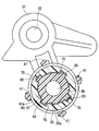
- FIG. 5 is a sectional view taken along line VV in FIG. 2.
- FIG. 6 is a cross-sectional view taken along line VI-VI in FIG. 5.
- FIG. 6 is a sectional view taken along line VII-VII in FIG. 5.
- FIG. 7 is an exploded view of FIG. 6.
- FIG. 8 is an exploded view of FIG. 7.
- the delivery pipe 1 is connected to the fuel injection valve 10 and is fixed to the intake pipe 20 by a bolt (not shown).
- the delivery pipe 1 supplies the fuel pumped up from the fuel tank 2 of the vehicle by the pump 3 and supplied through the pipe 4 to the fuel inlet 11 (see FIG. 10) of the fuel injection valve 10.
- the fuel tank 2 of the present embodiment corresponds to an example of a “fuel supply source” recited in the claims.
- the intake pipe 20 is formed with an intake passage 21 for introducing air taken from an intake duct (not shown) into the combustion chamber of the internal combustion engine.
- the intake pipe 20 has a hole 22 for communicating the intake passage 21 and the outside air.
- the hole 22 includes a small-diameter hole 23 into which the nozzle portion 12 of the fuel injection valve 10 can be inserted, and a large-diameter hole 24 having an inner diameter larger than the small-diameter hole 23 on the outside air side of the small-diameter hole 23.
- An annular seal member 25 is fitted in the large diameter hole 24.
- the seal member 25 is in contact with a step 26 formed at a connection portion between the small diameter hole 23 and the large diameter hole 24.
- the seal member 25 prevents air from leaking between the inner wall of the hole 22 of the intake pipe 20 and the nozzle portion 12 of the fuel injection valve 10.
- the delivery pipe 1 includes a main pipe 30, a feed pipe 40, a pipe connection pipe 50, a plurality of convex portions 60, a plurality of concave portions 70, and the like.
- the main pipe 30 and the feed pipe 40 are separate members.
- the feed pipe 40 and the pipe connection pipe 50 are integrally formed.
- the main pipe 30 has a fixed portion 31 that extends radially outward from its outer wall.
- the fixing portion 31 is provided with a bolt hole 32 for attaching a bolt (not shown).
- the main pipe 30 is attached to the intake pipe 20 by screwing a bolt passed through the bolt hole 32 into a screw hole (not shown) provided in the intake pipe 20.
- the fixing portion 31 has a positioning pin 33 that protrudes in parallel with the bolt hole 32. By inserting the positioning pin 33 into a hole (not shown) provided in the intake pipe 20, the main pipe 30 is prevented from rotating about the bolt passed through the bolt hole 32.
- the main pipe 30 is formed in a cylindrical shape and can be connected to the end of the fuel injection valve 10 on the fuel inlet 11 side.
- a contact surface 34 is provided at the end of the main pipe 30 opposite to the feed pipe 40 in the axial direction.
- the main pipe 30 has a first fuel passage 35 that supplies fuel to the fuel inlet 11 of the fuel injection valve 10.
- the fuel supplied from the first fuel passage 35 to the fuel inlet 11 of the fuel injection valve 10 passes through the inner flow path 14 of the fuel injection valve 10 and is injected from the injection hole 15 (see FIG. 2).
- the first O-ring 16 provided between the inner wall of the main pipe 30 and the outer wall of the fuel injection valve 10 prevents fuel leakage from between the inner wall of the main pipe 30 and the outer wall of the fuel injection valve 10. It is out.
- the feed pipe 40 is formed in a bottomed cylindrical shape, and includes a bottom portion 41, an inner cylindrical portion 42 extending in a cylindrical shape from the bottom portion 41, and an outer cylindrical portion 43 extending in a cylindrical shape from the bottom portion 41 outside the inner cylindrical portion 42. And have. A space 44 is provided between the inner cylinder portion 42 and the outer cylinder portion 43.
- the feed pipe 40 may be integrally formed without providing the space 44 between the inner cylinder part 42 and the outer cylinder part 43.
- the inner cylinder part 42 of the feed pipe 40 can be fitted inside the main pipe 30.
- the feed pipe 40 has a second fuel passage 45 inside the inner cylinder portion 42.
- the first fuel passage 35 of the main pipe 30 and the second fuel passage 45 of the feed pipe 40 communicate with each other.
- the second O-ring 46 provided between the inner wall of the main pipe 30 and the outer wall of the feed pipe 40 is a fuel from between the outer wall of the inner cylindrical portion 42 of the feed pipe 40 and the inner wall of the main pipe 30. Prevents leakage.
- the feed pipe 40 is provided with a plurality of arm portions 47 extending from the axial end surface of the outer cylinder portion 43 toward the main pipe 30 side. At the tips of the plurality of arm portions 47, claw portions 48 projecting inward in the radial direction are provided.
- the plurality of claw portions 48 are fitted to the step portion 36 provided on the outer wall of the main pipe 30 by snap fitting.
- the step portion 36 is provided continuously in the circumferential direction of the outer wall of the main pipe 30.
- claw part 48 are provided in the position shifted
- the pipe connection pipe 50 is formed integrally with the feed pipe 40 and extends from the outer wall of the feed pipe 40 in a direction intersecting the axis of the feed pipe 40.
- the pipe for pipe connection 50 has a third fuel passage 51 inside.
- the third fuel passage 51 of the pipe connection pipe 50 and the second fuel passage 45 of the feed pipe 40 communicate with each other.
- the pipe connection pipe 50 can be connected to the pipe 4 for supplying fuel from the fuel tank 2 described above (see FIG. 1).
- the fuel supplied from the pipe 4 is supplied to the fuel inlet 11 of the fuel injection valve 10 via the third fuel passage 51, the second fuel passage 45 and the first fuel passage 35.
- the outer wall 42 a of the inner cylinder portion 42 of the feed pipe 40 is provided with a convex portion 60 that protrudes in the radially outward direction.
- the number of protrusions 60 may be at least one and not more than the number of recesses 70.
- the inner wall 30a of the main pipe 30 that faces the inner cylinder portion 42 of the feed pipe 40 in the radial direction is provided with a plurality of recesses 70 that are recessed in the radially outward direction.
- four recesses 70 are illustrated, but it is sufficient that at least two recesses 70 are provided.
- the number of convex portions 60 and the number of concave portions 70 are all the same, four.
- the convex portion 60 has a size that can be fitted inside the concave portion 70.
- the some convex part 60 is the same shape, and the some recessed part 70 is also the same shape.
- the plurality of convex portions 60 and the plurality of concave portions 70 are all provided at equal intervals in the circumferential direction. Therefore, the main pipe 30 and the feed pipe 40 are assembled by changing the relative rotation angle at the angle between the adjacent convex portions 60 and the convex portions 60 or at the angle between the adjacent concave portions 70 and the concave portions 70 (90 ° in the present embodiment). It is possible.
- both the convex portion 60 and the concave portion 70 extend in the axial direction of the main pipe 30 and the feed pipe 40. Further, both the convex portion 60 and the concave portion 70 have an arc shape in cross section perpendicular to the axes of the main pipe 30 and the feed pipe 40. Accordingly, the feed pipe 40 or the main pipe 30 is moved in the axial direction as shown by the arrow M in FIG. 8 and the arrow N in FIG. It is possible to fit the recessed portion 70 formed. At this time, the direction in which the pipe connection pipe 50 extends can be changed with respect to the fixed portion 31 of the main pipe 30 by assembling the main pipe 30 and the feed pipe 40 while changing the relative rotation angle.
- the inner wall 30a of the main pipe 30 and the outer wall 42a of the inner cylindrical portion 42 of the feed pipe 40 are respectively the wall of the main pipe 30 and the wall of the feed pipe 40 of the present disclosure that face each other in the radial direction of the main pipe 30 and the feed pipe 40. It is composed.
- the fuel injection valve 10 is inserted inside the main pipe 30.
- the main pipe 30 is provided with an extending portion 37 extending from the contact surface 34 with which the flange portion 13 of the fuel injection valve 10 contacts to the injection hole 15 side of the fuel injection valve 10.
- a receiving portion 38 extending in the circumferential direction of the fuel injection valve 10 is provided at the end of the extending portion 37 on the injection hole 15 side.
- the extending portion 37 and the receiving portion 38 have a cross section perpendicular to the axis of the main pipe 30 formed in an arc shape along the outer wall of the fuel injection valve 10.
- the assembly of the main pipe 30 and the fuel injection valve 10 is performed by passing the connector 17 of the fuel injection valve 10 between the extending portion 37 and the receiving portion 38 as shown by an arrow X in FIG. Thereafter, as shown by an arrow Y, the fuel injection valve 10 is rotated around the axis. As a result, as shown in FIG. 2, the connector 17 is locked to the receiving portion 38, and the flange portion 13 abuts against the abutting surface 34, whereby the fuel injection valve 10 is restricted from moving in the axial direction. Further, the movement of the connector 17 in the circumferential direction is restricted by the circumferential end face 371 (see FIG. 10) of the extending portion 37 and the claw 39 provided in the receiving portion 38, so that the fuel injection valve 10 is moved around the axis. Rotation is regulated.
- the nozzle portion 12 of the fuel injection valve 10 is inserted into the hole 22 of the intake pipe 20, and the fixing portion 31 extending from the main pipe 30 is bolted to the intake pipe 20. Thereby, the fuel injection valve 10 and the delivery pipe 1 are fixed to the intake pipe 20.
- the delivery pipe 1 of the first embodiment described above has the following operational effects.
- at least one convex portion 60 is provided on the outer wall 42 a of the inner cylindrical portion 42 of the feed pipe 40.
- a plurality of recesses 70 are provided in the circumferential direction of the inner wall 30 a of the main pipe 30. The convex part 60 and the concave part 70 can be fitted.
- the relative rotation angle between the main pipe 30 and the feed pipe 40 is changed by changing the position where the plurality of concave portions 70 and the convex portions 60 are fitted.
- the relative position of the feed pipe 40 with respect to the main pipe 30 in the circumferential direction can be selected from a plurality of relative positions, and the respective positions of the plurality of recesses 70-74 in the circumferential direction are a plurality of positions.
- the delivery pipe 1 can change the direction of the pipe connection pipe 50 extending from the feed pipe 40 with respect to the main pipe 30 fixed to the internal combustion engine. Therefore, the delivery pipe 1 can be attached to various internal combustion engines by changing the direction of the pipe connection pipe 50 in accordance with the mounting position of the auxiliary machines of the internal combustion engine.
- the number of the plurality of concave portions 70 and the number of the convex portions 60 are the same.
- the delivery pipe 1 can prevent rattling between the main pipe 30 and the feed pipe 40 and can stably connect them.
- a plurality of convex portions 60 are provided at equal intervals in the circumferential direction.
- a plurality of recesses 70 are also provided at equal intervals in the circumferential direction.
- the main pipe 30 and the feed pipe 40 can be assembled with different relative rotation angles at the angles of the adjacent convex portions 60 and the convex portions 60 or the adjacent concave portions 70 and the concave portions 70.
- the convex portion 60 and the concave portion 70 extend in the axial direction of the main pipe 30 and the feed pipe 40.
- the convex portion 60 and the concave portion 70 can be easily fitted by moving them in the axial direction.
- the convex portion 60 and the concave portion 70 can reliably restrict the relative rotation between the main pipe 30 and the feed pipe 40 after the main pipe 30 and the feed pipe 40 are assembled.
- shaft of the convex part 60 and the recessed part 70 at the main pipe 30 and the feed pipe 40 is circular arc shape.
- the delivery pipe 1 can suppress the protrusions 60 and the recesses 70 from being worn when or after the main pipe 30 and the feed pipe 40 are assembled.
- the delivery pipe 1 includes an arm portion 47 that extends from the feed pipe 40 toward the main pipe 30, and a claw portion 48 provided at the tip of the arm portion 47.
- the claw portion 48 is fitted to the step portion 36 provided on the outer wall of the main pipe 30.
- the feed pipe 40 and the main pipe 30 can be easily assembled by snap fitting.
- the arm portion 47 and the claw portion 48 are provided at positions shifted from the convex portion 60 in the circumferential direction of the feed pipe 40.
- the feed pipe 40 provided with the arm portion 47, the claw portion 48, and the convex portion 60 is formed by resin injection molding, the mold part that forms the arm portion 47 and the claw portion 48 and the convex portion are formed in the mold release process. It can prevent that the site
- the feed pipe 40 when the feed pipe 40 is viewed from the radial direction, the convex portion 60 can be visually recognized without the convex portion 60 being hidden by the arm portion 47 and the claw portion 48. Therefore, the feed pipe 40 can easily perform product inspection of the convex portion 60.
- FIG. 1 A cross-sectional view of the delivery pipe 1 of the second embodiment of the present disclosure is shown in FIG.
- one convex portion 60 is provided on the outer wall 42 a of the inner cylindrical portion 42 of the feed pipe 40.
- three recesses 70 are provided in the inner wall 30a of the main pipe 30 that faces the inner cylinder portion 42 of the feed pipe 40 in the radial direction.
- three recesses 70 are illustrated, but it is sufficient that at least two recesses 70 are provided.
- the three recesses 70 have different circumferential intervals. That is, the angles of the adjacent recesses 70 and the recesses 70 are different from each other.
- the main pipe 30 and the feed pipe 40 can be assembled by changing the relative rotation angle between the main pipe 30 and the feed pipe 40 by fitting any one of the concave portions 70 and the convex portions 60 together. Thereby, the delivery pipe 1 can change the direction in which the pipe for pipe connection 50 extends with respect to the fixed portion 31 of the main pipe 30.
- FIG. 12 shows a cross-sectional view of the delivery pipe 1 according to the third embodiment of the present disclosure.
- four recesses 71-74 are provided in the outer wall 42 a of the inner cylinder portion 42 of the feed pipe 40.
- four convex portions 61-64 are provided on the inner wall 30 a of the main pipe 30 that faces the inner cylinder portion 42 of the feed pipe 40 in the radial direction. Note that the number of convex portions 61-64 may be at least one and not more than the number of concave portions 71-74.
- the four recesses 71-74 have different circumferential intervals.
- the four recesses 71-74 are referred to as a first recess 71 to a fourth recess 74 counterclockwise in FIG.
- the angle between the first recess 71 and the second recess 72 is ⁇ 1
- the angle between the second recess 72 and the third recess 73 is ⁇ 2
- the angle between the third recess 73 and the fourth recess 74 is ⁇ 3
- the fourth An angle formed by the recess 74 and the first recess 71 is ⁇ 4.
- the four convex portions 61-64 are also provided at the same angle as the four concave portions 71-74.
- a plurality of recesses 71-74 are provided in the circumferential direction of the outer wall 42a of the inner cylinder portion 42 of the feed pipe 40.
- the relative rotation angles of the main pipe 30 and the feed pipe 40 can be changed in four directions and assembled.
- FIG. 13 shows a cross-sectional view of the delivery pipe 1 of the fourth embodiment of the present disclosure.
- the convex portion 60 provided on the outer wall 42 a of the inner cylinder portion 42 of the feed pipe 40 and the concave portion 70 provided on the inner wall 30 a of the main pipe 30 are both of the main pipe 30 and the feed pipe 40.
- the cross section perpendicular to the axis is rectangular.
- the convex portion 60 has a size that can be fitted inside the concave portion 70.
- the some convex part 60 is the same shape, and the some recessed part 70 is also the same shape.
- the plurality of convex portions 60 and the plurality of concave portions 70 are all provided at equal intervals in the circumferential direction. Therefore, the main pipe 30 and the feed pipe 40 are assembled by changing the relative rotation angle at the angle between the adjacent convex portions 60 and the convex portions 60 or at the angle between the adjacent concave portions 70 and the concave portions 70 (90 ° in the present embodiment). It is possible.
- FIG. 1 A cross-sectional view of the delivery pipe 1 of the fifth embodiment of the present disclosure is shown in FIG.
- the plurality of arm portions 47 extending from the outer cylindrical portion 43 of the feed pipe 40 to the main pipe 30 side have a diameter of the feed pipe 40 with respect to the convex portion 60 provided on the outer wall 42 a of the inner cylindrical portion 42. It is provided at a position overlapping in the direction.
- the convex portion 60 is located on the inner side based on the positions of the arm portion 47 and the claw portion 48. It is possible to recognize. Therefore, the convex part 60 and the concave part 70 can be easily fitted.
- the concave portion 70 when the concave portion 70 is provided on the outer wall 42a of the inner cylindrical portion 42 of the feed pipe 40, the plurality of arm portions 47 are arranged in the radial direction of the feed pipe 40 with respect to the concave portion 70. You may provide in the overlapping position. With this configuration, when the feed pipe 40 and the main pipe 30 are assembled, it is possible to recognize that the concave portion 70 is located on the inner side based on the positions of the arm portion 47 and the claw portion 48.
- FIG. 15 is a cross-sectional view of the delivery pipe 1 according to the sixth embodiment of the present disclosure.
- a plurality of main pipes 301 and 302 are connected by a connecting pipe 80.
- the connecting pipe 80 has a communication passage 81 that communicates the first fuel passage 35 of one main pipe 301 with the first fuel passage 35 of the other main pipe 302.
- the feed pipe 40 is fitted to one main pipe 301.
- One main pipe 301 and the feed pipe 40 can be assembled at different relative rotation angles.
- the other main pipe 302 is formed in a bottomed cylindrical shape. Therefore, the first fuel passage 35 is closed on the side opposite to the fuel injection valve 10.
- the fuel supplied to the pipe connection pipe 50 includes a third fuel passage 51 included in the pipe connection pipe 50, a second fuel passage 45 included in the feed pipe 40, and a first fuel path 35 included in one main pipe 301. And is supplied to the fuel inlet 11 of one of the fuel injection valves 10.
- the fuel in the first fuel passage 35 of one main pipe 301 is supplied to the fuel inlet 11 of the other fuel injection valve 10 from the first fuel passage 35 of the other main pipe 302 via the communication passage 81. Is done.
- the delivery pipe 1 of the sixth embodiment can be applied to a multi-cylinder internal combustion engine.
- FIG. 16 A cross-sectional view of a delivery pipe 1 according to a seventh embodiment of the present disclosure is shown in FIG.
- the fuel injection valve 10 is indicated by a two-dot chain line.
- the feed pipe 40 is formed in a bottomed cylindrical shape, and includes a bottom portion 41 and a cylindrical portion 49 that extends from the bottom portion 41 in a cylindrical shape.
- the cylindrical portion 49 of the feed pipe 40 can be fitted to the outer periphery of the main pipe 30.
- An O-ring 461 provided between the inner wall 49 a of the cylindrical portion 49 of the feed pipe 40 and the outer wall 30 b of the main pipe 30 leaks fuel between the cylindrical portion 49 of the feed pipe 40 and the outer wall 30 b of the main pipe 30. Is preventing.
- the main pipe 30 is provided with a plurality of arm portions 47 extending from the outer peripheral wall to the feed pipe 40 side. At the tips of the plurality of arm portions 47, claw portions 48 projecting inward in the radial direction are provided. The plurality of claw portions 48 are fitted to the stepped portion 36 provided on the outer wall of the feed pipe 40 by snap fitting. The step portion 36 is provided continuously in the circumferential direction of the outer wall of the feed pipe 40.
- the inner wall 49a of the cylindrical portion 49 of the feed pipe 40 is provided with a convex portion 60 protruding in the radial direction.
- the number of convex parts 60 should just be at least 1 or more and the number of concave parts 70 or less.
- the outer wall 30b of the main pipe 30 that faces the cylindrical portion 49 of the feed pipe 40 in the radial direction is provided with a plurality of concave portions 70 that are recessed in the radial inner direction. It is sufficient that at least two recesses 70 are provided.
- the outer wall 30b of the main pipe 30 and the inner wall 49a of the cylindrical portion 49 of the feed pipe 40 constitute the wall of the main pipe 30 and the wall of the feed pipe 40 of the present disclosure that face each other in the radial direction of the main pipe 30 and the feed pipe 40, respectively. is doing.
- Both the convex portion 60 and the concave portion 70 extend in the axial direction of the main pipe 30 and the feed pipe 40.
- the convex portion 60 has a size that can be fitted inside the concave portion 70.
- the some convex part 60 is the same shape, and the some recessed part 70 is also the same shape. Therefore, the main pipe 30 and the feed pipe 40 can be assembled by changing the relative rotation angle according to the angle between the adjacent convex portions 60 and the convex portions 60 or the angle between the adjacent concave portions 70 and the concave portions 70. Therefore, the delivery pipe 1 can change the direction in which the pipe connection pipe 50 extends with respect to the fixing portion 31 of the main pipe 30.
- At least one convex portion 60 is provided on the inner wall 49a of the cylindrical portion 49 of the feed pipe 40.
- a plurality of concave portions 70 that can be fitted to the convex portions 60 are provided in the circumferential direction of the outer wall 30 b of the main pipe 30.
- the delivery pipe 1 that supplies fuel to the fuel injection valve 10 attached to the intake pipe 20 has been described.
- the fuel injection valve to which the delivery pipe 1 supplies fuel may be attached to, for example, a throttle body, an intake manifold, an exhaust pipe, a cylinder head, or a cylinder body.
- the concave portion 70 and the convex portion 60 have an arc shape or a rectangular shape in a cross section perpendicular to the axes of the feed pipe 40 and the main pipe 30.
- the concave portions 70 and the convex portions 60 may have a polygonal shape such as a triangle or a curved surface.
- the present disclosure is not limited to the above-described embodiments.
- the present disclosure can be implemented in various forms without departing from the spirit of the present disclosure. it can.
Landscapes
- Engineering & Computer Science (AREA)
- Chemical & Material Sciences (AREA)
- Combustion & Propulsion (AREA)
- Mechanical Engineering (AREA)
- General Engineering & Computer Science (AREA)
- Fuel-Injection Apparatus (AREA)
Abstract
デリバリパイプは、メインパイプ(30)、フィードパイプ(40)、配管接続用パイプ(50)、凸部(60)および凹部(70)を備える。メインパイプ(30)は、筒状に形成され、内燃機関に固定可能であると共に、燃料噴射弁(10)に接続可能である。フィードパイプ(40)は、有底筒状に形成され、メインパイプ(30)の内側に嵌合する。配管接続用パイプ(50)は、フィードパイプ(40)からフィードパイプ(40)の軸に対し交差する方向に延びる。フィードパイプ(40)の外壁に少なくとも1個の凸部(60)が設けられる。フィードパイプ(40)と径方向に向き合うメインパイプ(30)の内壁の周方向に複数個の凹部(70)が設けられる。これにより、メインパイプ(30)とフィードパイプ(40)は、複数個の凹部(70)と凸部(60)とを嵌合する位置を変えて組み付けることが可能である。
Description
本願は、2015年2月4日に出願された日本国特許出願第2015-20395号に基づくものであり、この開示をもってその内容を本明細書中に開示したものとする。
本開示は、燃料噴射弁に燃料を供給するデリバリパイプに関する。
従来、車両の燃料タンクから供給された燃料を燃料噴射弁に供給するデリバリパイプが知られている。
特許文献1に記載のデリバリパイプは、内燃機関のスロットルボディに固定されると共に燃料噴射弁の燃料入口側の端部に取り付けられる有底筒状のキャップ部と、そのキャップ部から径方向へ延びる管状のジョイント部を備えている。そのジョイント部には、燃料タンクから汲み上げられた燃料が流れる配管が接続される。デリバリパイプは、配管からジョイント部に供給された燃料を、キャップ部を経由して燃料噴射弁の燃料入口に供給する。
しかしながら、特許文献1に記載のデリバリパイプは、内燃機関のスロットルボディに固定されるキャップ部に対し、ジョイント部が延びる向きが固定されている。そのため、このデリバリパイプを、特許文献1に記載の内燃機関とは補機類の搭載位置などが異なる他の内燃機関に取り付ける場合、デリバリパイプのジョイント部と補機類とが干渉するおそれがある。
この場合、特許文献1に記載のデリバリパイプの構成であれば、内燃機関の補機類の搭載位置に適合するように、キャップ部に対するジョイント部が延びる向きを変更したデリバリパイプを新たに設計し、複数の種類のデリバリパイプを管理しなければならない。したがって、デリバリパイプの設計コスト及び管理コストなどが増大することが懸念される。
或いは、デリバリパイプのジョイント部と内燃機関の補機類とが干渉しないように、内燃機関の補機類の搭載位置を変更しなければならない。
本開示は、上記問題に鑑みてなされたものであり、種々の内燃機関に取り付けることが可能なデリバリパイプを提供することを目的とする。
本開示のデリバリパイプは、内燃機関に固定され、燃料供給源から配管を通じて供給される燃料を燃料噴射弁に供給する。デリバリパイプは、メインパイプ、フィードパイプ、配管接続用パイプ、少なくとも1個の凸部および複数個の凹部を備える。内燃機関に固定可能であると共に燃料噴射弁に接続可能な筒状のメインパイプは、燃料噴射弁が有する燃料入口へ燃料を供給する第1燃料通路を有する。メインパイプの内側または外側に嵌合する有底筒状のフィードパイプは、第1燃料通路に連通する第2燃料通路を有する。フィードパイプからメインパイプ及びフィードパイプの軸に対し交差する方向に延びて配管に接続可能な配管接続用パイプは、第2燃料通路に連通する第3燃料通路を有する。少なくとも1つの凸部は、メインパイプ及びフィードパイプの径方向に互いに対向するメインパイプの壁と、フィードパイプの壁とのうちの一方に設けられている。複数個の凹部は、上記のメインパイプの壁と、フィードパイプの壁とのうちの他方において、メインパイプ及びフィードパイプの周方向に互いに離間して設けられている。メインパイプに対するフィードパイプの相対回転を規制すべく少なくとも1個の凸部は複数個の凹部のうちの少なくとも1個と嵌合可能に設けられている。
これにより、デリバリパイプは、複数個の凹部と凸部とを嵌合する位置を変えることにより、内燃機関に固定可能なメインパイプに対し、フィードパイプから延びる配管接続用パイプの向きを変えることが可能である。したがって、本開示のデリバリパイプは、種々の内燃機関に取り付けることができる。
なお、本明細書において、デリバリパイプが固定される内燃機関とは、スロットルボディ、インテークマニホールド、吸気管、排気管、シリンダヘッドおよびシリンダ本体などを総称していうものとする。
以下、本開示の複数の実施形態を図面に基づいて説明する。なお、複数の実施形態において、実質的に同一の構成には、図面に同一の符号を付して説明を省略する。
(第1実施形態)
本開示の第1実施形態を図1~図10を参照して説明する。なお、図6,7では、燃料噴射弁10を2点鎖線で示している。
本開示の第1実施形態を図1~図10を参照して説明する。なお、図6,7では、燃料噴射弁10を2点鎖線で示している。
図1に示すように、デリバリパイプ1は、燃料噴射弁10に接続されると共に、図示していないボルトにより吸気管20に固定される。デリバリパイプ1は、車両の燃料タンク2からポンプ3によって汲み上げられ配管4を通じて供給された燃料を燃料噴射弁10の燃料入口11(図10参照)に供給する。本実施形態の燃料タンク2は、特許請求の範囲に記載の「燃料供給源」の一例に相当する。
吸気管20には、図示していない吸気ダクトから取り入れた空気を内燃機関の燃焼室に導入する吸気通路21が形成されている。また、吸気管20は、吸気通路21と外気とを連通する孔22を有している。この孔22は、燃料噴射弁10のノズル部12を挿入可能な小径孔23、及び、その小径孔23の外気側で小径孔23よりも内径が大きい大径孔24から構成されている。大径孔24には、円環状のシール部材25が嵌め込まれている。シール部材25は、小径孔23と大径孔24との接続箇所に形成された段差26に当接している。シール部材25は、吸気管20の孔22の内壁と燃料噴射弁10のノズル部12との間から空気が漏れることを防いでいる。
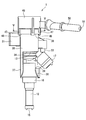
図2~図4に示すように、デリバリパイプ1は、メインパイプ30、フィードパイプ40、配管接続用パイプ50、複数の凸部60および複数の凹部70などを備えている。メインパイプ30とフィードパイプ40とは、別部材である。また、フィードパイプ40と配管接続用パイプ50とは、一体に形成されている。
メインパイプ30は、その外壁から径外方向に延びる固定部31を有する。固定部31には、ボルト(図示していない)を取り付けるためのボルト孔32が設けられている。このボルト孔32に通したボルトを吸気管20に設けられたねじ穴(図示していない)に螺合することにより、メインパイプ30は吸気管20に取り付けられる。また、固定部31は、ボルト孔32と平行に突出する位置決めピン33を有する。この位置決めピン33を吸気管20に設けられた穴(図示していない)に差し込むことにより、ボルト孔32に通したボルトを軸としたメインパイプ30の回転が防がれる。
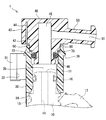
図6及び図7に示すように、メインパイプ30は筒状に形成され、燃料噴射弁10の燃料入口11側の端部に接続可能である。メインパイプ30の軸方向のフィードパイプ40とは反対側の端部には、当接面34が設けられている。この当接面34に対し、燃料噴射弁10の外壁に設けられたフランジ部13が当接することにより、燃料噴射弁10のフィードパイプ40側への移動が規制される。
メインパイプ30は、燃料噴射弁10の燃料入口11へ燃料を供給する第1燃料通路35を有する。第1燃料通路35から燃料噴射弁10の燃料入口11へ供給された燃料は、燃料噴射弁10の内側流路14を通り、噴孔15から噴射される(図2参照)。なお、メインパイプ30の内壁と燃料噴射弁10の外壁との間に設けられた第1のOリング16は、メインパイプ30の内壁と燃料噴射弁10の外壁との間からの燃料漏れを防いでいる。
フィードパイプ40は、有底筒状に形成され、底部41と、その底部41から筒状に延びる内筒部42と、その内筒部42の外側で底部41から筒状に延びる外筒部43とを有する。内筒部42と外筒部43との間には空間44が設けられている。なお、フィードパイプ40は、内筒部42と外筒部43との間に空間44を設けることなく、これらを一体に形成してもよい。
フィードパイプ40の内筒部42は、メインパイプ30の内側に嵌合可能である。フィードパイプ40は、内筒部42の内側に第2燃料通路45を有する。メインパイプ30の第1燃料通路35とフィードパイプ40の第2燃料通路45とは連通している。なお、メインパイプ30の内壁とフィードパイプ40の外壁との間に設けられた第2のOリング46は、フィードパイプ40の内筒部42の外壁とメインパイプ30の内壁との間からの燃料漏れを防いでいる。
フィードパイプ40には、外筒部43の軸方向の端面からメインパイプ30側へ延びる複数の腕部47が設けられている。この複数の腕部47の先端にはそれぞれ径内方向に突出する爪部48が設けられている。複数の爪部48は、メインパイプ30の外壁に設けられた段差部36に対し、スナップフィットにより嵌合する。なお、段差部36は、メインパイプ30の外壁の周方向に連続して設けられている。
なお、腕部47と爪部48は、後述する凸部60に対し、フィードパイプ40の周方向にずれた位置に設けられている。
配管接続用パイプ50は、フィードパイプ40と一体に形成され、フィードパイプ40の外壁からフィードパイプ40の軸に対し交差する方向に延びている。配管接続用パイプ50は、内側に第3燃料通路51を有する。配管接続用パイプ50の第3燃料通路51とフィードパイプ40の第2燃料通路45とは連通している。
配管接続用パイプ50は、上述した燃料タンク2から燃料を供給する配管4に接続可能である(図1参照)。その配管4から供給される燃料は、第3燃料通路51、第2燃料通路45および第1燃料通路35を経由し、燃料噴射弁10の燃料入口11に供給される。
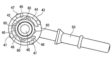
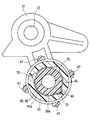
図3から図5に示すように、フィードパイプ40の内筒部42の外壁42aには、径外方向に突出する凸部60が設けられている。本実施形態では、4個の凸部60が例示されているが、凸部60の個数は、少なくとも1個以上、且つ、凹部70の個数以下であればよい。
フィードパイプ40の内筒部42に対して径方向に向き合うメインパイプ30の内壁30aには、径外方向に凹む複数の凹部70が設けられている。本実施形態では、4個の凹部70が例示されているが、凹部70は少なくとも2個以上設けられていればよい。
本実施形態では、凸部60の数と凹部70の数はいずれも4個で同一である。凸部60は、凹部70の内側に嵌合可能な大きさである。また、複数の凸部60は同一の形状であり、複数の凹部70も同一の形状である。
また、本実施形態では、複数の凸部60と複数の凹部70は、いずれも周方向に等間隔に設けられている。そのため、隣り合う凸部60と凸部60の角度、又は隣り合う凹部70と凹部70の角度(本実施形態では90°)にて、メインパイプ30とフィードパイプ40は相対回転角を変えて組み付けることが可能である。
凸部60と凹部70は、いずれもメインパイプ30及びフィードパイプ40の軸方向に延びている。また、凸部60と凹部70は、いずれもメインパイプ30及びフィードパイプ40の軸に垂直な断面が円弧状である。これにより、図8の矢印M及び図9の矢印Nに示すように、フィードパイプ40またはメインパイプ30を軸方向に移動し、フィードパイプ40に設けられた凸部60と、メインパイプ30に設けられた凹部70とを嵌合することが可能である。このとき、メインパイプ30とフィードパイプ40との相対回転角を変えて組み付けることにより、メインパイプ30の固定部31に対し、配管接続用パイプ50が延出する方向を変えることができる。メインパイプ30の内壁30aおよびフィードパイプ40の内筒部42の外壁42aは、メインパイプ30およびフィードパイプ40の径方向に互いに対向する本開示のメインパイプ30の壁及びフィードパイプ40の壁をそれぞれ構成している。
続いて、図10に示すように、メインパイプ30の内側に燃料噴射弁10を挿入する。メインパイプ30には、燃料噴射弁10のフランジ部13が当接する当接面34から燃料噴射弁10の噴孔15側へ延びる延伸部37が設けられている。また、延伸部37の噴孔15側の端部には、燃料噴射弁10の周方向に延びる受部38が設けられている。延伸部37と受部38は、メインパイプ30の軸に垂直な断面が、燃料噴射弁10の外壁に沿った円弧状に形成されている。
メインパイプ30と燃料噴射弁10との組み付けは、図10の矢印Xに示すように、燃料噴射弁10は、延伸部37と受部38との間に燃料噴射弁10のコネクタ17を通した後、矢印Yに示すように、燃料噴射弁10を軸周りに回転する。これにより、図2に示すように、コネクタ17が受部38に係止され、フランジ部13が当接面34に当接することにより、燃料噴射弁10は軸方向の移動が規制される。また、延伸部37の周方向の端面371(図10参照)と、受部38に設けられた爪39によりコネクタ17の周方向の移動が規制されることにより、燃料噴射弁10は軸周りの回転が規制される。
この状態で、図1に示すように、燃料噴射弁10のノズル部12を吸気管20の孔22に挿入し、メインパイプ30から延びる固定部31を吸気管20にボルト止めする。これにより、燃料噴射弁10とデリバリパイプ1は吸気管20に固定される。
上述した第1実施形態のデリバリパイプ1は、次の作用効果を奏する。
(1)第1実施形態では、フィードパイプ40の内筒部42の外壁42aに少なくとも1個の凸部60が設けられる。また、メインパイプ30の内壁30aの周方向に複数個の凹部70が設けられる。その凸部60と凹部70は嵌合可能である。
(1)第1実施形態では、フィードパイプ40の内筒部42の外壁42aに少なくとも1個の凸部60が設けられる。また、メインパイプ30の内壁30aの周方向に複数個の凹部70が設けられる。その凸部60と凹部70は嵌合可能である。
これにより、複数の凹部70と凸部60とを嵌合する位置を変えることにより、メインパイプ30とフィードパイプ40との相対回転角が変わる。別の言い方をすれば、周方向におけるメインパイプ30に対するフィードパイプ40の相対位置は、複数の相対位置から選択可能であり、周方向における複数個の凹部70-74のそれぞれの位置は、複数の相対位置のうちの1つに対応している。そのため、デリバリパイプ1は、内燃機関に固定されるメインパイプ30に対し、フィードパイプ40から延びる配管接続用パイプ50の向きを変えることが可能である。したがって、デリバリパイプ1は、内燃機関の補機類の搭載位置等に応じて配管接続用パイプ50の向きを変えることにより、種々の内燃機関に取り付けることができる。
(2)第1実施形態では、複数の凹部70の数と、凸部60の数とは同一である。
これにより、複数の凸部60と複数の凹部70が嵌合する。したがって、デリバリパイプ1は、メインパイプ30とフィードパイプ40とのがたつきを防ぎ、これらを安定して接続することが可能である。
(3)第1実施形態では、凸部60は、複数個が周方向に等間隔で設けられる。凹部70も、複数個が周方向に等間隔で設けられる。
これにより、隣り合う凸部60と凸部60、又は隣り合う凹部70と凹部70の角度にて、メインパイプ30とフィードパイプ40は相対回転角を変えて組み付けることが可能になる。
(4)第1実施形態では、凸部60と凹部70は、メインパイプ30及びフィードパイプ40の軸方向に延びている。
これにより、メインパイプ30とフィードパイプ40を組み付ける際、これらを軸方向に移動することにより、凸部60と凹部70とを容易に嵌合することが可能である。
また、凸部60と凹部70は、メインパイプ30とフィードパイプ40とを組み付けた後に、メインパイプ30とフィードパイプ40との相対回転を確実に規制することが可能である。
(5)第1実施形態では、凸部60と凹部70は、メインパイプ30及びフィードパイプ40の軸に垂直な断面が円弧状である。
これにより、凸部60と凹部70に角張った箇所が形成されない。そのため、デリバリパイプ1は、メインパイプ30とフィードパイプ40を組み付ける際、または組付けた後にも、凸部60と凹部70が摩耗することを抑制することができる。
(6)第1実施形態では、デリバリパイプ1は、フィードパイプ40からメインパイプ30側へ延びる腕部47と、その腕部47の先端に設けられた爪部48を備える。爪部48は、メインパイプ30の外壁に設けられた段差部36に嵌合する。
これにより、フィードパイプ40とメインパイプ30をスナップフィットにより容易に組み付けることができる。
(7)第1実施形態では、腕部47と爪部48は、凸部60に対し、フィードパイプ40の周方向にずれた位置に設けられる。
これにより、腕部47、爪部48及び凸部60が設けられたフィードパイプ40を樹脂射出形成する際、型抜き工程において、腕部47と爪部48を形成する金型の部位と、凸部60を形成する金型の部位とが干渉することを防ぐことができる。したがって、樹脂射出形成の際、金型からフィードパイプ40を容易に型抜きすることができる。
また、フィードパイプ40を径方向から見たとき、腕部47と爪部48に凸部60が隠れることなく、凸部60を視認することが可能である。したがって、このフィードパイプ40は、凸部60の製品検査を容易に行うことができる。
(第2実施形態)
本開示の第2実施形態のデリバリパイプ1の断面図を図11に示す。第2実施形態では、フィードパイプ40の内筒部42の外壁42aに1個の凸部60が設けられている。また、フィードパイプ40の内筒部42に対して径方向に向き合うメインパイプ30の内壁30aに3個の凹部70が設けられている。なお、第2実施形態では、3個の凹部70が例示されているが、凹部70は少なくとも2個以上設けられていればよい。
本開示の第2実施形態のデリバリパイプ1の断面図を図11に示す。第2実施形態では、フィードパイプ40の内筒部42の外壁42aに1個の凸部60が設けられている。また、フィードパイプ40の内筒部42に対して径方向に向き合うメインパイプ30の内壁30aに3個の凹部70が設けられている。なお、第2実施形態では、3個の凹部70が例示されているが、凹部70は少なくとも2個以上設けられていればよい。
第2実施形態では、3個の凹部70は、周方向の間隔がそれぞれ異なっている。即ち、隣り合う凹部70と凹部70の角度はそれぞれ異なっている。メインパイプ30とフィードパイプ40は、いずれか1個の凹部70と凸部60とを嵌合することにより、メインパイプ30とフィードパイプ40の相対回転角を変えて組み付けることが可能である。これにより、デリバリパイプ1は、メインパイプ30の固定部31に対し、配管接続用パイプ50が延びる方向を変えることができる。
(第3実施形態)
本開示の第3実施形態のデリバリパイプ1の断面図を図12に示す。第3実施形態では、フィードパイプ40の内筒部42の外壁42aに4個の凹部71-74が設けられている。また、フィードパイプ40の内筒部42に対して径方向に向き合うメインパイプ30の内壁30aに4個の凸部61-64が設けられている。なお、凸部61-64の個数は、少なくとも1個以上、且つ、凹部71-74の個数以下であればよい。
本開示の第3実施形態のデリバリパイプ1の断面図を図12に示す。第3実施形態では、フィードパイプ40の内筒部42の外壁42aに4個の凹部71-74が設けられている。また、フィードパイプ40の内筒部42に対して径方向に向き合うメインパイプ30の内壁30aに4個の凸部61-64が設けられている。なお、凸部61-64の個数は、少なくとも1個以上、且つ、凹部71-74の個数以下であればよい。
第3実施形態では、4個の凹部71-74は、周方向の間隔がそれぞれ異なっている。説明のため、図12の紙面左回りに、4個の凹部71-74を第1凹部71~第4凹部74と称する。第1凹部71と第2凹部72とのなす角をθ1、第2凹部72と第3凹部73とのなす角をθ2、第3凹部73と第4凹部74とのなす角をθ3、第4凹部74と第1凹部71とのなす角をθ4とする。このとき、θ1=θ3、θ2=θ4 である。なお、4個の凸部61-64も、4個の凹部71-74と同じ角度で設けられている。
第3実施形態では、フィードパイプ40の内筒部42の外壁42aの周方向に複数個の凹部71-74が設けられる。これにより、メインパイプ30とフィードパイプ40は、凹部71-74と凸部61-64とを嵌合することにより、メインパイプ30とフィードパイプ40の相対回転角を2方向に変えて組み付けることが可能である。
なお、メインパイプ30の内壁30aに1個のみ凸部を設けた場合には、メインパイプ30とフィードパイプ40の相対回転角を4方向に変えて組み付けることが可能である。
(第4実施形態)
本開示の第4実施形態のデリバリパイプ1の断面図を図13に示す。第4実施形態では、フィードパイプ40の内筒部42の外壁42aに設けられた凸部60と、メインパイプ30の内壁30aに設けられた凹部70は、いずれもメインパイプ30及びフィードパイプ40の軸に垂直な断面が矩形状である。凸部60は、凹部70の内側に嵌合可能な大きさである。また、複数の凸部60は同一の形状であり、複数の凹部70も同一の形状である。
本開示の第4実施形態のデリバリパイプ1の断面図を図13に示す。第4実施形態では、フィードパイプ40の内筒部42の外壁42aに設けられた凸部60と、メインパイプ30の内壁30aに設けられた凹部70は、いずれもメインパイプ30及びフィードパイプ40の軸に垂直な断面が矩形状である。凸部60は、凹部70の内側に嵌合可能な大きさである。また、複数の凸部60は同一の形状であり、複数の凹部70も同一の形状である。
第4実施形態では、複数の凸部60と複数の凹部70は、いずれも周方向に等間隔で設けられている。そのため、隣り合う凸部60と凸部60の角度、又は隣り合う凹部70と凹部70の角度(本実施形態では90°)にて、メインパイプ30とフィードパイプ40は相対回転角を変えて組み付けることが可能である。
(第5実施形態)
本開示の第5実施形態のデリバリパイプ1の断面図を図14に示す。第5実施形態では、フィードパイプ40の外筒部43からメインパイプ30側へ延びる複数の腕部47は、内筒部42の外壁42aに設けられた凸部60に対し、フィードパイプ40の径方向に重なる位置に設けられる。
本開示の第5実施形態のデリバリパイプ1の断面図を図14に示す。第5実施形態では、フィードパイプ40の外筒部43からメインパイプ30側へ延びる複数の腕部47は、内筒部42の外壁42aに設けられた凸部60に対し、フィードパイプ40の径方向に重なる位置に設けられる。
一般に、フィードパイプ40とメインパイプ30とを組み付ける際、凸部60又は凹部70の位置を視認することは困難である。そこで、第5実施形態では、上述した構成により、フィードパイプ40とメインパイプ30とを組み付ける際、腕部47及び爪部48の位置に基づき、その内側に凸部60が位置していることを認識することが可能である。したがって、凸部60と凹部70を容易に嵌合することができる。
なお、第5実施形態の変形例として、フィードパイプ40の内筒部42の外壁42aに凹部70を設けた場合、複数の腕部47は、その凹部70に対し、フィードパイプ40の径方向に重なる位置に設けてもよい。この構成により、フィードパイプ40とメインパイプ30とを組み付ける際、腕部47及び爪部48の位置に基づき、その内側に凹部70が位置していることを認識することが可能である。
(第6実施形態)
本開示の第6実施形態のデリバリパイプ1の断面図を図15に示す。第6実施形態では、複数のメインパイプ301,302が連結管80によって接続されている。連結管80は、一方のメインパイプ301が有する第1燃料通路35と、他方のメインパイプ302が有する第1燃料通路35とを連通する連通路81を有している。
本開示の第6実施形態のデリバリパイプ1の断面図を図15に示す。第6実施形態では、複数のメインパイプ301,302が連結管80によって接続されている。連結管80は、一方のメインパイプ301が有する第1燃料通路35と、他方のメインパイプ302が有する第1燃料通路35とを連通する連通路81を有している。
第6実施形態では、一方のメインパイプ301にフィードパイプ40が嵌合している。一方のメインパイプ301とフィードパイプ40とは、相対回転角を変えて組み付けることが可能である。
他方のメインパイプ302は、有底筒状に形成されている。そのため、第1燃料通路35は、燃料噴射弁10とは反対側が閉塞されている。配管接続用パイプ50に供給された燃料は、配管接続用パイプ50が有する第3燃料通路51、フィードパイプ40が有する第2燃料通路45、及び、一方のメインパイプ301が有する第1燃料通路35を経由し、一方の燃料噴射弁10の燃料入口11に供給される。また、一方のメインパイプ301が有する第1燃料通路35の燃料は、連通路81を経由し、他方のメインパイプ302が有する第1燃料通路35から他方の燃料噴射弁10の燃料入口11に供給される。
第6実施形態のデリバリパイプ1は、多気筒の内燃機関に適用することが可能である。
(第7実施形態)
本開示の第7実施形態のデリバリパイプ1の断面図を図16に示す。なお、図16では、燃料噴射弁10を2点鎖線で示している。第7実施形態では、フィードパイプ40は、有底筒状に形成され、底部41と、その底部41から筒状に延びる筒部49とを有する。フィードパイプ40の筒部49は、メインパイプ30の外周に嵌合可能である。フィードパイプ40の筒部49の内壁49aとメインパイプ30の外壁30bとの間に設けられたOリング461は、フィードパイプ40の筒部49とメインパイプ30の外壁30bとの間からの燃料漏れを防いでいる。
本開示の第7実施形態のデリバリパイプ1の断面図を図16に示す。なお、図16では、燃料噴射弁10を2点鎖線で示している。第7実施形態では、フィードパイプ40は、有底筒状に形成され、底部41と、その底部41から筒状に延びる筒部49とを有する。フィードパイプ40の筒部49は、メインパイプ30の外周に嵌合可能である。フィードパイプ40の筒部49の内壁49aとメインパイプ30の外壁30bとの間に設けられたOリング461は、フィードパイプ40の筒部49とメインパイプ30の外壁30bとの間からの燃料漏れを防いでいる。
メインパイプ30には、外周壁からフィードパイプ40側へ延びる複数の腕部47が設けられている。この複数の腕部47の先端にはそれぞれ径内方向に突出する爪部48が設けられている。複数の爪部48は、フィードパイプ40の外壁に設けられた段差部36に対し、スナップフィットにより嵌合する。なお、段差部36は、フィードパイプ40の外壁の周方向に連続して設けられている。
フィードパイプ40の筒部49の内壁49aには、径内方向に突出する凸部60が設けられている。凸部60の個数は、少なくとも1個以上、且つ、凹部70の個数以下であればよい。一方、フィードパイプ40の筒部49に対して径方向に向き合うメインパイプ30の外壁30bには、径内方向に凹む複数の凹部70が設けられている。凹部70は少なくとも2個以上設けられていればよい。メインパイプ30の外壁30bおよびフィードパイプ40の筒部49の内壁49aは、メインパイプ30およびフィードパイプ40の径方向に互いに対向する本開示のメインパイプ30の壁及びフィードパイプ40の壁をそれぞれ構成している。
凸部60と凹部70は、いずれもメインパイプ30及びフィードパイプ40の軸方向に延びている。凸部60は、凹部70の内側に嵌合可能な大きさである。また、複数の凸部60は同一の形状であり、複数の凹部70も同一の形状である。そのため、メインパイプ30とフィードパイプ40は、隣り合う凸部60と凸部60の角度、又は隣り合う凹部70と凹部70の角度にて、相対回転角を変えて組み付けることが可能である。したがって、デリバリパイプ1は、メインパイプ30の固定部31に対し、配管接続用パイプ50が延びる方向を変えることができる。
第7実施形態では、フィードパイプ40の筒部49の内壁49aに少なくとも1個の凸部60が設けられる。その凸部60に嵌合可能な凹部70は、メインパイプ30の外壁30bの周方向に複数個設けられる。
これにより、複数の凹部70と凸部60とを嵌合する位置を変えることにより、メインパイプ30とフィードパイプ40との相対回転角を変えて組み付けることが可能である。
(他の実施形態)
(1)上述した実施形態では、吸気管20に取り付けられる燃料噴射弁10に燃料を供給するデリバリパイプ1について説明した。これに対し、他の実施形態では、デリバリパイプ1が燃料を供給する燃料噴射弁は、例えばスロットルボディ、インテークマニホールド、排気管、シリンダヘッドまたはシリンダ本体などに取り付けられるものであってもよい。
(1)上述した実施形態では、吸気管20に取り付けられる燃料噴射弁10に燃料を供給するデリバリパイプ1について説明した。これに対し、他の実施形態では、デリバリパイプ1が燃料を供給する燃料噴射弁は、例えばスロットルボディ、インテークマニホールド、排気管、シリンダヘッドまたはシリンダ本体などに取り付けられるものであってもよい。
(2)上述した実施形態では、凹部70及び凸部60は、フィードパイプ40及びメインパイプ30の軸に垂直な断面を円弧状または矩形状とした。これに対し、他の実施形態では、凹部70及び凸部60は、その断面を三角等の多角形状または曲面状としてもよい。
このように、本開示は、上述した実施形態に限定されるものではなく、上述した複数の実施形態を組み合わせることに加え、本開示の趣旨を逸脱しない範囲において、種々の形態で実施することができる。
Claims (9)
- 内燃機関(20)に固定され、燃料供給源(2)から配管(4)を通じて供給される燃料を燃料噴射弁(10)に供給するデリバリパイプであって、
前記内燃機関(20)に固定可能であると共に前記燃料噴射弁(10)に接続可能であり、前記燃料噴射弁(10)が有する燃料入口(11)へ燃料を供給する第1燃料通路(35)を有する筒状のメインパイプ(30,301,302)と、
前記メインパイプ(30,301,302)の内側または外側に嵌合し、前記第1燃料通路(35)に連通する第2燃料通路(45)を有する有底筒状のフィードパイプ(40)と、
前記フィードパイプ(40)から前記メインパイプ(30,301,302)及び前記フィードパイプ(40)の軸に対し交差する方向に延びて前記配管(4)に接続可能であり、前記第2燃料通路(45)に連通する第3燃料通路(51)を有する配管接続用パイプ(50)と、
前記メインパイプ(30,301,302)及び前記フィードパイプ(40)の径方向に互いに対向する前記メインパイプ(30,301,302)の壁(30a,30b)と、前記フィードパイプ(40)の壁(42a,49a)とのうちの一方に設けられた少なくとも1個の凸部(60-64)と、
前記メインパイプ(30,301,302)の前記壁(30a,30b)と、前記フィードパイプ(40)の前記壁(42a,49a)とのうちの他方において、前記メインパイプ(30,301,302)及び前記フィードパイプ(40)の周方向に互いに離間して設けられた複数個の凹部(70-74)と
を備え、前記メインパイプ(30,301,302)に対する前記フィードパイプ(40)の相対回転を規制すべく前記少なくとも1個の凸部(60-64)は前記複数個の凹部(70-74)のうちの少なくとも1個と嵌合可能に設けられているデリバリパイプ。 - 前記少なくとも1個の凸部(60-64)は、前記メインパイプ(30,301,302)の前記壁(30a,30b)と、前記フィードパイプ(40)の前記壁(42a,49a)とのうちの前記一方に設けられた複数個の凸部(60-64)を含み、
前記複数個の凹部(70-74)の数と、前記複数個の凸部(60-64)の数とは同一である請求項1に記載のデリバリパイプ。 - 前記複数個の凸部(60)は、前記メインパイプ(30,301,302)の前記壁(30a,30b)と、前記フィードパイプ(40)の前記壁(42a,49a)とのうちの前記一方に前記周方向に等間隔で設けられ、
前記複数個の凹部(70)は、前記メインパイプ(30,301,302)の前記壁(30a,30b)と、前記フィードパイプ(40)の前記壁(42a,49a)とのうちの前記他方に前記周方向に等間隔で設けられる請求項2に記載のデリバリパイプ。 - 前記少なくとも1個の凸部(60-64)と前記複数個の凹部(70-74)は、前記メインパイプ(30,301,302)及び前記フィードパイプ(40)の軸方向にそれぞれ延びている請求項1から3のいずれか一項に記載のデリバリパイプ。
- 前記少なくとも1個の凸部(60-64)と前記複数個の凹部(70-74)は、前記メインパイプ(30,301,302)及び前記フィードパイプ(40)の軸に垂直な断面がそれぞれ円弧状である請求項1から4のいずれか一項に記載のデリバリパイプ。
- 前記フィードパイプ(40)及び前記メインパイプ(30,301,302)の一方から他方へ延びる腕部(47)と、
前記腕部(47)の先端に設けられ、前記フィードパイプ(40)及び前記メインパイプ(30,301,302)の他方の外壁に設けられた段差部に嵌合する爪部(48)と、を備える請求項1から5のいずれか一項に記載のデリバリパイプ。 - 前記腕部(47)及び前記爪部(48)は、前記少なくとも1個の凸部(60-64)又は前記複数個の凹部(70-74)に対し、前記メインパイプ(30,301,302)及び前記フィードパイプ(40)の前記周方向にずれた位置に設けられる請求項6に記載のデリバリパイプ。
- 前記腕部(47)及び前記爪部(48)は、前記少なくとも1個の凸部(60-64)又は前記複数個の凹部(70-74)の少なくとも1個に対し、前記メインパイプ(30,301,302)及び前記フィードパイプ(40)の径方向に重なる位置に設けられる請求項6に記載のデリバリパイプ。
- 前記周方向における前記メインパイプ(30,301,302)に対する前記フィードパイプ(40)の相対位置は、複数の相対位置から選択可能であり、前記周方向における前記複数個の凹部(70-74)のそれぞれの位置は、前記複数の相対位置のうちの1つに対応している請求項1から8のいずれか一項に記載のデリバリパイプ。
Priority Applications (1)
| Application Number | Priority Date | Filing Date | Title |
|---|---|---|---|
| CN201680003504.6A CN107110091B (zh) | 2015-02-04 | 2016-01-21 | 输送管 |
Applications Claiming Priority (2)
| Application Number | Priority Date | Filing Date | Title |
|---|---|---|---|
| JP2015-020395 | 2015-02-04 | ||
| JP2015020395A JP6361520B2 (ja) | 2015-02-04 | 2015-02-04 | デリバリパイプ |
Publications (1)
| Publication Number | Publication Date |
|---|---|
| WO2016125440A1 true WO2016125440A1 (ja) | 2016-08-11 |
Family
ID=56563797
Family Applications (1)
| Application Number | Title | Priority Date | Filing Date |
|---|---|---|---|
| PCT/JP2016/000286 Ceased WO2016125440A1 (ja) | 2015-02-04 | 2016-01-21 | デリバリパイプ |
Country Status (3)
| Country | Link |
|---|---|
| JP (1) | JP6361520B2 (ja) |
| CN (1) | CN107110091B (ja) |
| WO (1) | WO2016125440A1 (ja) |
Families Citing this family (1)
| Publication number | Priority date | Publication date | Assignee | Title |
|---|---|---|---|---|
| US12326129B1 (en) * | 2024-05-15 | 2025-06-10 | S & S Diesel Motorsport LLC | Rotatable bypass assembly for fuel system |
Citations (3)
| Publication number | Priority date | Publication date | Assignee | Title |
|---|---|---|---|---|
| JP2006266132A (ja) * | 2005-03-23 | 2006-10-05 | Keihin Corp | 燃料噴射弁の取り付け構造 |
| JP2007170257A (ja) * | 2005-12-21 | 2007-07-05 | Keihin Corp | 多連スロットルボデーにおける燃料供給構造 |
| JP2010236641A (ja) * | 2009-03-31 | 2010-10-21 | Denso Corp | コネクタ |
Family Cites Families (4)
| Publication number | Priority date | Publication date | Assignee | Title |
|---|---|---|---|---|
| JPS63125171U (ja) * | 1987-02-09 | 1988-08-16 | ||
| JP4405111B2 (ja) * | 2001-08-06 | 2010-01-27 | 株式会社ケーヒン | 燃料噴射弁保持装置 |
| JP2003129918A (ja) * | 2001-10-25 | 2003-05-08 | Aisan Ind Co Ltd | デリバリパイプ |
| JP2010093905A (ja) * | 2008-10-06 | 2010-04-22 | Sanyo Denki Co Ltd | ブラシレスモータ用ステータ |
-
2015
- 2015-02-04 JP JP2015020395A patent/JP6361520B2/ja active Active
-
2016
- 2016-01-21 CN CN201680003504.6A patent/CN107110091B/zh active Active
- 2016-01-21 WO PCT/JP2016/000286 patent/WO2016125440A1/ja not_active Ceased
Patent Citations (3)
| Publication number | Priority date | Publication date | Assignee | Title |
|---|---|---|---|---|
| JP2006266132A (ja) * | 2005-03-23 | 2006-10-05 | Keihin Corp | 燃料噴射弁の取り付け構造 |
| JP2007170257A (ja) * | 2005-12-21 | 2007-07-05 | Keihin Corp | 多連スロットルボデーにおける燃料供給構造 |
| JP2010236641A (ja) * | 2009-03-31 | 2010-10-21 | Denso Corp | コネクタ |
Also Published As
| Publication number | Publication date |
|---|---|
| JP6361520B2 (ja) | 2018-07-25 |
| CN107110091A (zh) | 2017-08-29 |
| CN107110091B (zh) | 2019-08-16 |
| JP2016142227A (ja) | 2016-08-08 |
Similar Documents
| Publication | Publication Date | Title |
|---|---|---|
| US7017953B2 (en) | Twist lock assembly | |
| CN104975986A (zh) | 双壁燃料供应线路元件和用于所述元件的连接法兰 | |
| EP2093411B1 (en) | Coupling device | |
| JPH0749011Y2 (ja) | フユーエルデリバリパイプ | |
| EP3112735B1 (en) | Joint unit | |
| US20050035595A1 (en) | Fuel-injector manifold assembly | |
| CN102834603A (zh) | 燃料喷射器组件 | |
| JP6361520B2 (ja) | デリバリパイプ | |
| US10443743B2 (en) | Rotary plug valve | |
| US9309820B2 (en) | Device for metering fuel | |
| CN114174671B (zh) | 模块化和可扩展的轨道的燃料系统架构 | |
| US12215658B2 (en) | Fuel injector with radially orientable nozzle holes using splines | |
| CN109098904B (zh) | 摩托车发动机及燃油分配装置 | |
| WO2016125441A1 (ja) | デリバリパイプ及び燃料供給装置 | |
| WO2013092366A1 (en) | Valve assembly for an injection valve and injection valve | |
| JP2012197786A (ja) | フューエルデリバリパイプ | |
| JP2013072416A (ja) | フューエルデリバリパイプ | |
| JP2025123079A (ja) | フューエルデリバリパイプ及びスロットル装置 | |
| US10801449B2 (en) | Airflow control valve structure and intake device | |
| US20250155062A1 (en) | Female element for fluidic connector | |
| CN214836781U (zh) | 进气管总成 | |
| JP5502541B2 (ja) | 燃料噴射弁の取り付け構造 | |
| JP2544331Y2 (ja) | フユーエルデリバリパイプ | |
| JP2007032474A (ja) | 燃料噴射弁の取付構造及び燃料供給システム | |
| EP3168453B1 (en) | Interface assembly for a fuel injector |
Legal Events
| Date | Code | Title | Description |
|---|---|---|---|
| 121 | Ep: the epo has been informed by wipo that ep was designated in this application |
Ref document number: 16746274 Country of ref document: EP Kind code of ref document: A1 |
|
| NENP | Non-entry into the national phase |
Ref country code: DE |
|
| 122 | Ep: pct application non-entry in european phase |
Ref document number: 16746274 Country of ref document: EP Kind code of ref document: A1 |