WO2016125423A1 - 研磨布立ち上げ方法及び研磨方法 - Google Patents
研磨布立ち上げ方法及び研磨方法 Download PDFInfo
- Publication number
- WO2016125423A1 WO2016125423A1 PCT/JP2016/000011 JP2016000011W WO2016125423A1 WO 2016125423 A1 WO2016125423 A1 WO 2016125423A1 JP 2016000011 W JP2016000011 W JP 2016000011W WO 2016125423 A1 WO2016125423 A1 WO 2016125423A1
- Authority
- WO
- WIPO (PCT)
- Prior art keywords
- polishing
- cloth
- residue
- polishing cloth
- dummy
- Prior art date
- Legal status (The legal status is an assumption and is not a legal conclusion. Google has not performed a legal analysis and makes no representation as to the accuracy of the status listed.)
- Ceased
Links
Images




Classifications
-
- B—PERFORMING OPERATIONS; TRANSPORTING
- B24—GRINDING; POLISHING
- B24B—MACHINES, DEVICES, OR PROCESSES FOR GRINDING OR POLISHING; DRESSING OR CONDITIONING OF ABRADING SURFACES; FEEDING OF GRINDING, POLISHING, OR LAPPING AGENTS
- B24B53/00—Devices or means for dressing or conditioning abrasive surfaces
- B24B53/017—Devices or means for dressing, cleaning or otherwise conditioning lapping tools
-
- B—PERFORMING OPERATIONS; TRANSPORTING
- B24—GRINDING; POLISHING
- B24B—MACHINES, DEVICES, OR PROCESSES FOR GRINDING OR POLISHING; DRESSING OR CONDITIONING OF ABRADING SURFACES; FEEDING OF GRINDING, POLISHING, OR LAPPING AGENTS
- B24B37/00—Lapping machines or devices; Accessories
-
- B—PERFORMING OPERATIONS; TRANSPORTING
- B24—GRINDING; POLISHING
- B24B—MACHINES, DEVICES, OR PROCESSES FOR GRINDING OR POLISHING; DRESSING OR CONDITIONING OF ABRADING SURFACES; FEEDING OF GRINDING, POLISHING, OR LAPPING AGENTS
- B24B37/00—Lapping machines or devices; Accessories
- B24B37/005—Control means for lapping machines or devices
-
- B—PERFORMING OPERATIONS; TRANSPORTING
- B24—GRINDING; POLISHING
- B24B—MACHINES, DEVICES, OR PROCESSES FOR GRINDING OR POLISHING; DRESSING OR CONDITIONING OF ABRADING SURFACES; FEEDING OF GRINDING, POLISHING, OR LAPPING AGENTS
- B24B37/00—Lapping machines or devices; Accessories
- B24B37/04—Lapping machines or devices; Accessories designed for working plane surfaces
- B24B37/07—Lapping machines or devices; Accessories designed for working plane surfaces characterised by the movement of the work or lapping tool
- B24B37/08—Lapping machines or devices; Accessories designed for working plane surfaces characterised by the movement of the work or lapping tool for double side lapping
-
- B—PERFORMING OPERATIONS; TRANSPORTING
- B24—GRINDING; POLISHING
- B24B—MACHINES, DEVICES, OR PROCESSES FOR GRINDING OR POLISHING; DRESSING OR CONDITIONING OF ABRADING SURFACES; FEEDING OF GRINDING, POLISHING, OR LAPPING AGENTS
- B24B37/00—Lapping machines or devices; Accessories
- B24B37/11—Lapping tools
- B24B37/20—Lapping pads for working plane surfaces
- B24B37/24—Lapping pads for working plane surfaces characterised by the composition or properties of the pad materials
-
- B—PERFORMING OPERATIONS; TRANSPORTING
- B24—GRINDING; POLISHING
- B24B—MACHINES, DEVICES, OR PROCESSES FOR GRINDING OR POLISHING; DRESSING OR CONDITIONING OF ABRADING SURFACES; FEEDING OF GRINDING, POLISHING, OR LAPPING AGENTS
- B24B49/00—Measuring or gauging equipment for controlling the feed movement of the grinding tool or work; Arrangements of indicating or measuring equipment, e.g. for indicating the start of the grinding operation
- B24B49/12—Measuring or gauging equipment for controlling the feed movement of the grinding tool or work; Arrangements of indicating or measuring equipment, e.g. for indicating the start of the grinding operation involving optical means
-
- B—PERFORMING OPERATIONS; TRANSPORTING
- B24—GRINDING; POLISHING
- B24B—MACHINES, DEVICES, OR PROCESSES FOR GRINDING OR POLISHING; DRESSING OR CONDITIONING OF ABRADING SURFACES; FEEDING OF GRINDING, POLISHING, OR LAPPING AGENTS
- B24B49/00—Measuring or gauging equipment for controlling the feed movement of the grinding tool or work; Arrangements of indicating or measuring equipment, e.g. for indicating the start of the grinding operation
- B24B49/18—Measuring or gauging equipment for controlling the feed movement of the grinding tool or work; Arrangements of indicating or measuring equipment, e.g. for indicating the start of the grinding operation taking regard of the presence of dressing tools
-
- B—PERFORMING OPERATIONS; TRANSPORTING
- B24—GRINDING; POLISHING
- B24B—MACHINES, DEVICES, OR PROCESSES FOR GRINDING OR POLISHING; DRESSING OR CONDITIONING OF ABRADING SURFACES; FEEDING OF GRINDING, POLISHING, OR LAPPING AGENTS
- B24B51/00—Arrangements for automatic control of a series of individual steps in grinding a workpiece
-
- B—PERFORMING OPERATIONS; TRANSPORTING
- B24—GRINDING; POLISHING
- B24B—MACHINES, DEVICES, OR PROCESSES FOR GRINDING OR POLISHING; DRESSING OR CONDITIONING OF ABRADING SURFACES; FEEDING OF GRINDING, POLISHING, OR LAPPING AGENTS
- B24B55/00—Safety devices for grinding or polishing machines; Accessories fitted to grinding or polishing machines for keeping tools or parts of the machine in good working condition
- B24B55/06—Dust extraction equipment on grinding or polishing machines
-
- G—PHYSICS
- G01—MEASURING; TESTING
- G01N—INVESTIGATING OR ANALYSING MATERIALS BY DETERMINING THEIR CHEMICAL OR PHYSICAL PROPERTIES
- G01N23/00—Investigating or analysing materials by the use of wave or particle radiation, e.g. X-rays or neutrons, not covered by groups G01N3/00 – G01N17/00, G01N21/00 or G01N22/00
- G01N23/22—Investigating or analysing materials by the use of wave or particle radiation, e.g. X-rays or neutrons, not covered by groups G01N3/00 – G01N17/00, G01N21/00 or G01N22/00 by measuring secondary emission from the material
- G01N23/223—Investigating or analysing materials by the use of wave or particle radiation, e.g. X-rays or neutrons, not covered by groups G01N3/00 – G01N17/00, G01N21/00 or G01N22/00 by measuring secondary emission from the material by irradiating the sample with X-rays or gamma-rays and by measuring X-ray fluorescence
-
- H—ELECTRICITY
- H10—SEMICONDUCTOR DEVICES; ELECTRIC SOLID-STATE DEVICES NOT OTHERWISE PROVIDED FOR
- H10P—GENERIC PROCESSES OR APPARATUS FOR THE MANUFACTURE OR TREATMENT OF DEVICES COVERED BY CLASS H10
- H10P52/00—Grinding, lapping or polishing of wafers, substrates or parts of devices
-
- H—ELECTRICITY
- H10—SEMICONDUCTOR DEVICES; ELECTRIC SOLID-STATE DEVICES NOT OTHERWISE PROVIDED FOR
- H10P—GENERIC PROCESSES OR APPARATUS FOR THE MANUFACTURE OR TREATMENT OF DEVICES COVERED BY CLASS H10
- H10P52/00—Grinding, lapping or polishing of wafers, substrates or parts of devices
- H10P52/40—Chemomechanical polishing [CMP]
- H10P52/402—Chemomechanical polishing [CMP] of semiconductor materials
-
- H—ELECTRICITY
- H10—SEMICONDUCTOR DEVICES; ELECTRIC SOLID-STATE DEVICES NOT OTHERWISE PROVIDED FOR
- H10P—GENERIC PROCESSES OR APPARATUS FOR THE MANUFACTURE OR TREATMENT OF DEVICES COVERED BY CLASS H10
- H10P70/00—Cleaning of wafers, substrates or parts of devices
- H10P70/20—Cleaning during device manufacture
-
- H—ELECTRICITY
- H10—SEMICONDUCTOR DEVICES; ELECTRIC SOLID-STATE DEVICES NOT OTHERWISE PROVIDED FOR
- H10P—GENERIC PROCESSES OR APPARATUS FOR THE MANUFACTURE OR TREATMENT OF DEVICES COVERED BY CLASS H10
- H10P72/00—Handling or holding of wafers, substrates or devices during manufacture or treatment thereof
- H10P72/06—Apparatus for monitoring, sorting, marking, testing or measuring
- H10P72/0604—Process monitoring, e.g. flow or thickness monitoring
-
- H—ELECTRICITY
- H10—SEMICONDUCTOR DEVICES; ELECTRIC SOLID-STATE DEVICES NOT OTHERWISE PROVIDED FOR
- H10P—GENERIC PROCESSES OR APPARATUS FOR THE MANUFACTURE OR TREATMENT OF DEVICES COVERED BY CLASS H10
- H10P90/00—Preparation of wafers not covered by a single main group of this subclass, e.g. wafer reinforcement
- H10P90/12—Preparing bulk and homogeneous wafers
- H10P90/123—Preparing bulk and homogeneous wafers by grinding or lapping
-
- G—PHYSICS
- G01—MEASURING; TESTING
- G01N—INVESTIGATING OR ANALYSING MATERIALS BY DETERMINING THEIR CHEMICAL OR PHYSICAL PROPERTIES
- G01N2223/00—Investigating materials by wave or particle radiation
- G01N2223/60—Specific applications or type of materials
- G01N2223/611—Specific applications or type of materials patterned objects; electronic devices
- G01N2223/6116—Specific applications or type of materials patterned objects; electronic devices semiconductor wafer
-
- G—PHYSICS
- G01—MEASURING; TESTING
- G01N—INVESTIGATING OR ANALYSING MATERIALS BY DETERMINING THEIR CHEMICAL OR PHYSICAL PROPERTIES
- G01N2223/00—Investigating materials by wave or particle radiation
- G01N2223/60—Specific applications or type of materials
- G01N2223/652—Specific applications or type of materials impurities, foreign matter, trace amounts
Definitions
- the present invention relates to a method for starting up a polishing cloth for polishing a silicon wafer and a method for polishing a silicon wafer using the polishing cloth.
- scratching of the wafer and the particle level may be significantly deteriorated in polishing immediately after the polishing cloth is attached to the polishing machine. Further, the larger the polishing machine, the more easily this scratch and particle level deteriorates. Such scratches and particle level deterioration are considered to be caused by insufficient rise of the polishing cloth immediately after pasting.
- the present invention has been made to solve the above problems, and an object of the present invention is to provide a polishing cloth start-up method that can improve the particle level at the initial stage of the polishing cloth life. Another object of the present invention is to provide a polishing method capable of improving the particle level at the initial stage of the polishing cloth life.
- the present invention provides a method for starting up a polishing cloth for polishing a silicon wafer, which comprises attaching a polishing cloth made of urethane foam resin to a polishing machine, performing dressing, and then performing a dummy. After performing polishing and then removing the polishing residue accumulated in the polishing cloth by the dummy polishing, the amount of polishing residue in the polishing cloth is measured, and the dummy residue is measured based on the measured amount of polishing residue.
- a polishing cloth raising method for determining the rising edge of a polished polishing cloth.
- the polishing cloth is set up by dummy polishing in addition to dressing, and further, after the dummy polishing, it is determined whether the polishing cloth has sufficiently started up.
- the polishing cloth can be started up, and as a result, the particle level at the initial stage of the polishing cloth life can be improved.
- the determination is performed by polishing a silicon wafer using a reference polishing cloth made of urethane foam resin that has been separately dressed in advance, removing the polishing residue by the same means as the removal process after the dummy polishing, and The amount of the polishing residue after the removal treatment is measured, and the polishing in the reference polishing cloth at the time when the value of (use time of the reference polishing cloth) / (preliminary life of the reference polishing cloth) is 0.05 It is preferable to determine the amount of residue as a reference value, and to determine that the polishing cloth subjected to the dummy polishing has risen if the amount of polishing residue measured after the dummy polishing and removal treatment is equal to or greater than the reference value.
- Such a method can more reliably determine whether or not the polishing cloth after dummy polishing has risen sufficiently, so that the particle level at the initial stage of the polishing cloth life can be improved more reliably.
- the amount of the polishing residue is measured by detecting a signal containing Si—K ⁇ rays from a fluorescent X-ray spectrum obtained by fluorescent X-ray analysis. With such a method, the amount of polishing residue can be easily measured.
- the polishing machine can be, for example, a double-side polishing machine.
- the polishing cloth startup method of the present invention can also be applied when using a double-side polishing machine.
- the present invention is a method for polishing a silicon wafer using a polishing cloth, and a polishing cloth made of urethane foam resin is attached to a polishing machine, dressing is performed, dummy polishing is performed, and then the dummy polishing is performed.
- a polishing cloth used for polishing the silicon wafer is measured based on the measured amount of polishing residue after the removal of the polishing residue accumulated in the polishing cloth is performed by measuring the amount of polishing residue in the polishing cloth.
- a polishing method for polishing the silicon wafer using the selected polishing cloth is a method for polishing a silicon wafer using the selected polishing cloth.
- the polishing cloth is set up by dummy polishing in addition to dressing, and the polishing cloth sufficiently raised by dummy polishing is selected and used for polishing.
- the level can be improved.
- the selection is performed by polishing a silicon wafer using a reference polishing cloth made of urethane foam resin that has been separately dressed in advance, removal of polishing residues by the same means as the removal processing after the dummy polishing, and The amount of the polishing residue after the removal treatment is measured, and the polishing in the reference polishing cloth at the time when the value of (use time of the reference polishing cloth) / (preliminary life of the reference polishing cloth) is 0.05 It is preferable to obtain a residue amount as a reference value, and to select a polishing cloth whose polishing residue amount measured after the dummy polishing and removal process is equal to or more than the reference value as a polishing cloth used for polishing the silicon wafer.
- Such a method can more reliably improve the level of particles at the initial stage of the polishing cloth life, since it is possible to more reliably select the polishing cloth that has risen sufficiently.
- the amount of the polishing residue is measured by detecting a signal containing Si—K ⁇ rays from a fluorescent X-ray spectrum obtained by fluorescent X-ray analysis. With such a method, the amount of polishing residue can be easily measured.
- the polishing machine can be, for example, a double-side polishing machine.
- the polishing method of the present invention can also be applied when using a double-side polishing machine.
- the polishing cloth startup method of the present invention the polishing cloth is started up by dummy polishing in addition to the conventional dressing, and the polishing cloth after dummy polishing is observed to generate scratches and particle deterioration.
- the polishing cloth In order to determine whether the polishing cloth is sufficiently raised, it is possible to start the polishing cloth until the polishing cloth is sufficiently raised, and as a result, it is possible to improve the particle level at the initial stage of the polishing cloth. Further, since it is sufficient to finish the dummy polishing when it is determined that the polishing cloth has risen, the polishing cloth can be efficiently started up without performing dummy polishing for an unnecessarily long time.
- the polishing cloth is set up by dummy polishing in addition to dressing, and further, the polishing cloth that has risen sufficiently to the extent that scratches and particle deterioration are not observed by dummy polishing is selected. Therefore, since it is used for polishing, the particle level at the initial stage of the polishing cloth life can be improved.
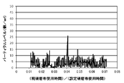
- FIG. 6 shows the particle level at each polishing cloth use time when the main polishing is performed after the start-up by the conventional method.
- the life of the polishing cloth is early, especially until the value of (current polishing cloth use time) / (set polishing cloth use time) is 0.05. Shows that the particle level is getting worse.
- the present inventors diligently studied to improve the particle level in the early stage of the polishing pad, and focused on the amount of polishing residue in the polishing pad and the rising of the polishing pad.
- a large amount of polishing residue is accumulated in the polishing cloth compared to the initial stage of the polishing cloth life, It has been found that the rising state of the polishing cloth can be determined by the amount of polishing residue in the polishing cloth.
- dummy polishing was performed and polishing residues were accumulated in the polishing cloth to start up the polishing cloth.
- the rising edge was determined based on the amount of polishing residue after dummy polishing, and it was determined that it had sufficiently started up. It was found that the particle level at the initial stage of the polishing cloth life can be improved by performing the main polishing using the polishing cloth, and the present invention has been completed.
- the present invention is a method for starting up a polishing cloth for polishing a silicon wafer, a polishing cloth made of urethane foam resin is attached to a polishing machine, dressing is performed, dummy polishing is performed, After performing the removal process of the polishing residue accumulated in the polishing cloth by dummy polishing, the amount of polishing residue in the polishing cloth is measured, and the polishing cloth is subjected to the dummy polishing based on the measured amount of polishing residue This is a polishing cloth starting method for determining the rising edge of the polishing cloth.
- FIG. 1 is a flowchart showing an example of the polishing cloth startup method of the present invention.
- a polishing cloth made of urethane foam resin is attached to a polishing machine (FIG. 1 (1a)), dressing is performed (FIG. 1 (1b)), and then dummy polishing is performed ( 1 (1c)), and after removing the polishing residue accumulated in the polishing cloth by dummy polishing (FIG. 1 (1d)), the amount of polishing residue in the polishing cloth is measured (FIG. 1 (1e)). )), The rising of the polishing cloth subjected to the dummy polishing is determined based on the measured polishing residue amount (FIG. 1 (1f)).
- a polishing cloth made of urethane foam resin is attached to a polishing machine (FIG. 1 (1a)).
- the polishing machine is not particularly limited, but for example, a double-sided polishing machine or the like can be suitably used.
- the polishing cloth startup method of the present invention can be applied regardless of the size of the polishing machine.
- dressing is performed (FIG. 1 (1b)).
- the dressing method is not particularly limited, for example, a dresser or the like that is usually used for starting up an abrasive cloth and in which diamond is spread on the surface can be suitably used.
- dummy polishing is performed (FIG. 1 (1c)).
- the polishing residue accumulated in the polishing cloth is removed between the polishing (for example, the polishing cloth is scraped using a dresser with diamonds (dressing), or polishing)
- a treatment (such as high pressure jet water washing) is performed by applying high pressure jet water to the cloth.
- this removing process is performed, most of the polishing residue accumulated in the polishing cloth is removed, but a part of the polishing residue remains in the polishing cloth even after the removing process, and the polishing cloth is started up. Therefore, in the polishing cloth startup method of the present invention, dummy polishing is performed after dressing, the polishing residue is intentionally accumulated in the polishing cloth, and the polishing cloth is started up.
- the dummy polishing is not particularly limited, and for example, a silicon wafer generally used for dummy polishing can be suitably used. Moreover, it does not specifically limit as an abrasive
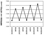
- FIG. 7 shows a change in the amount of polishing residue when the polishing of the wafer and the removal processing of the polishing residue are alternately repeated.
- the polishing allowance per polishing at this time was 15 ⁇ m.
- a dummy is continuously formed so that a normal polishing (polishing allowance: about 10 ⁇ m to 20 ⁇ m) is performed without removing the removal process and a plurality of polishing allowances are obtained. It is preferable to perform polishing. More specifically, it is preferable to perform dummy polishing continuously so as to obtain a polishing allowance of, for example, about 30 ⁇ m to 150 ⁇ m, more preferably about 50 ⁇ m to 100 ⁇ m.
- polishing residue accumulated in the polishing cloth is removed by dummy polishing (FIG. 1 (1d)).
- polishing residue is not specifically limited, For example, it is preferable to carry out by dressing and high-pressure jet water washing.
- the dresser etc. which spread the diamond on the surface can be used suitably for dressing like the said dressing before dummy grinding
- the amount of polishing residue measured here is the amount of polishing residue remaining in the polishing cloth after the above-described removal treatment.
- the method for measuring the polishing residue amount is not particularly limited, but it is preferable to detect and measure a signal containing Si—K ⁇ rays from a fluorescent X-ray spectrum obtained by, for example, fluorescent X-ray analysis.
- the amount of polishing residue When measuring the amount of polishing residue by fluorescent X-ray analysis, it can be specifically measured by the following method.
- the polishing residue accumulated in the polishing cloth contains Si element. Therefore, if a signal containing Si-K ⁇ ray is detected from the fluorescent X-ray spectrum, the amount of polishing residue can be measured. Can do. More specifically, the value obtained by integrating the signal amount in the range of 1.6 to 1.9 eV including the Si—K ⁇ ray from the detected fluorescent X-ray spectrum should be used as a guide value for the polishing residue amount. (Hereinafter, this reference value is referred to as “Si signal amount”).
- MESA-630 manufactured by HORIBA, Ltd. can be used for the measurement of the amount of Si signal, and the measurement recipe in that case is, for example, Alloy LE FP, and the X-ray irradiation time is preferably 60 seconds.
- the Si signal amount of the polishing cloth subjected to the dummy polishing is measured, and the Si signal amount is used as the polishing residue amount, whereby the polishing residue amount can be easily measured.
- the rising edge of the polishing cloth subjected to the dummy polishing is determined based on the measured polishing residue amount (FIG. 1 (1f)).
- the determination is performed by using a polishing cloth for reference made of urethane foam resin that has been separately dressed in advance, polishing the silicon wafer, removal processing of the polishing residue by the same means as the removal processing after dummy polishing, and removal processing
- the amount of polishing residue in the reference polishing cloth at the time when the value of (the usage time of the reference polishing cloth) / (preset life of the reference polishing cloth) is 0.05 is measured Is determined as a reference value, and if the amount of polishing residue measured after the dummy polishing and removal treatment is equal to or greater than the reference value, it is preferable to determine that the polishing cloth subjected to dummy polishing has risen.
- the determination method is not limited to this.
- a reference value that is a criterion for determination is obtained. More specifically, the silicon wafer is polished using a urethane foam polishing cloth (reference polishing cloth) that has been separately dressed only (starting up with the conventional method), and then the polishing residue is removed. After the removal treatment, the amount of polishing residue is measured, and the amount of polishing residue at the time when the value of (current polishing cloth use time) / (set polishing cloth use time) of the reference polishing cloth is 0.05 is used as a reference. Calculate as a value. At this time, the removal process of the polishing residue is performed by the same means as the removal process after the dummy polishing described above.
- the actual judgment is made. More specifically, the amount of polishing residue measured after performing the dummy polishing and removal treatment as described above (that is, the amount of polishing residue in the polishing cloth subjected to dummy polishing) and the reference obtained as described above. The values are compared, and if the amount of polishing residue in the polishing cloth subjected to dummy polishing is equal to or greater than the reference value, it is determined that the polishing cloth subjected to dummy polishing has risen.
- FIG. 8 shows the amount of polishing residue when each polishing cloth is used when actual polishing is actually performed after startup by the conventional method.
- the amount of polishing residue shown here is a value measured after the removal treatment of the polishing residue.
- the reference value in the above determination method is, for example, a value (about 4200) indicated by a dotted line in FIG.
- Such a determination method can more reliably determine whether or not the polishing cloth after dummy polishing has risen sufficiently, so that the particle level at the initial stage of the polishing cloth life can be improved more reliably.
- it since it is possible to accurately determine the rise, it is not necessary to perform further dummy polishing. Therefore, waste of time and cost due to unnecessary dummy polishing can be reduced, and startup can be performed efficiently.
- the polishing cloth startup method of the present invention the polishing cloth is started up by dummy polishing in addition to the conventional dressing, and the polishing cloth after dummy polishing is observed to generate scratches and particle deterioration. As a result, it is possible to start up the polishing cloth until the polishing cloth sufficiently rises up, and to effectively improve the particle level at the initial stage of the polishing cloth life. it can.
- the present invention is a method of polishing a silicon wafer using a polishing cloth, and a polishing cloth made of urethane foam resin is attached to a polishing machine, dressing is performed, dummy polishing is performed, and then the dummy polishing is performed.
- a polishing cloth used for polishing the silicon wafer is measured based on the measured amount of polishing residue after the removal of the polishing residue accumulated in the polishing cloth is performed by measuring the amount of polishing residue in the polishing cloth.
- a polishing method for polishing the silicon wafer using the selected polishing cloth is a method of polishing a silicon wafer using a polishing cloth.
- FIG. 2 is a flowchart showing an example of the polishing method of the present invention.
- a polishing cloth made of urethane foam resin is attached to a polishing machine (FIG. 2 (2a)), dressing is performed (FIG. 2 (2b)), and dummy polishing is then performed (FIG. 2 (2)). 2c)), and then after removing the polishing residue accumulated in the polishing cloth by dummy polishing (FIG. 2 (2d)), the amount of polishing residue in the polishing cloth is measured (FIG. 2 (2e)), A polishing cloth used for polishing the silicon wafer is selected based on the measured polishing residue amount (FIG. 2 (2f)), and the silicon wafer is polished using the selected polishing cloth (FIG. 2 (2g)).
- a polishing cloth made of urethane foam resin is attached to a polishing machine (FIG. 2 (2a)).
- a polishing machine As a grinder, the thing similar to the thing quoted by the above-mentioned polishing cloth starting method of the present invention can be used.
- dressing is performed (FIG. 2 (2b)).
- the dressing may be performed in the same manner as the dressing in the above-described polishing cloth startup method of the present invention.
- dummy polishing is performed (FIG. 2 (2c)).
- the dummy polishing may be performed in the same manner as the dummy polishing in the above-described polishing cloth startup method of the present invention.
- polishing residue removal process may be performed in the same manner as the polishing residue removal process in the above-described polishing cloth startup method of the present invention.
- the amount of polishing residue in the polishing cloth is measured (FIG. 2 (2e)).
- the measurement of the polishing residue amount may be performed in the same manner as the measurement of the polishing residue amount in the above-described polishing cloth startup method of the present invention.
- the polishing cloth used for polishing the silicon wafer is selected based on the measured polishing residue amount (FIG. 2 (2f)).
- the selection may be performed in the same manner as the determination of the rising of the polishing cloth in the above-described polishing cloth starting method of the present invention. Specifically, what is determined to have risen in the above determination may be selected as a polishing cloth used for polishing a silicon wafer.
- polishing cloth that was not selected is the above-described dummy polishing (FIG. 2 (2c)), removal processing of polishing residue (FIG. 2 (2d)), measurement of the amount of polishing residue (FIG. 2 (2e)), and selection. (FIG. 2 (2f)) may be repeated until selection.
- the silicon wafer is polished using the selected polishing cloth (FIG. 2 (2g)).
- polishing agent the thing similar to what was mentioned by the dummy grinding
- the polishing cloth is set up by dummy polishing in addition to dressing, and the polishing is sufficiently started up to the extent that scratches and particle deterioration are not observed by dummy polishing. Since the cloth is selected and used for polishing, the particle level in the initial stage of the polishing cloth life can be improved.
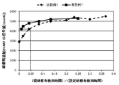
- FIG. 4 shows the amount of polishing residue in each polishing cloth usage time.
- FIG. 6 shows the particle level at each polishing cloth use time. At this time, the amount of polishing residue when the value of (current polishing cloth usage time) / (set polishing cloth usage time) was 0.05 was determined as a reference value.
- Polishing machine used 30B double-side polishing machine
- Sample wafer CZ, P-type, crystal orientation ⁇ 100>, diameter 300 mm
- Polishing cloth foamed urethane resin
- Polishing agent colloidal silica polishing polishing load: 180 g / cm 2 Polishing allowance: 15 ⁇ m
- Example 1 A polishing cloth made of urethane foam resin is attached to a polishing machine, and dressing of the polishing cloth is performed using a dresser in which diamonds are spread on the surface, and then the conditions of polishing load 200 g / cm 2 and polishing allowance 15 ⁇ m (the following dummy polishing) Conditions), dummy polishing was performed five times in succession, and the amount of polishing residue was measured every time 15 ⁇ m dummy polishing was performed. After repeating the dummy polishing and measurement of the amount of polishing residue five times, as a polishing residue removal process, dressing the polishing cloth using a dresser with diamonds on the surface, and then washing the polishing cloth with high-pressure jet water Went. Thereafter, the amount of polishing residue after the removal treatment was measured. The amount of polishing residue for each 15 ⁇ m of dummy polishing and the amount of polishing residue after removal treatment are shown in FIG.
- Polishing machine used 30B double-side polishing machine
- Sample wafer CZ, P type, crystal orientation ⁇ 100>, diameter 300 mm
- Polishing cloth foamed urethane resin
- Polishing agent colloidal silica polishing polishing load: 200 g / cm 2 Polishing allowance: 15 ⁇ m
- Example 1 When the amount of polishing residue after removal treatment measured in Example 1 was compared with the reference value obtained in advance in Comparative Example 1, the amount of polishing residue after removal treatment was more than the reference value. 1 was determined to have stood up, and was selected as a polishing cloth used for the main polishing described later.
- FIG. 4 shows the amount of polishing residue in each polishing cloth usage time. Moreover, the particle level in each polishing cloth use time is shown in FIG.
- Example 1 when the value of (current polishing cloth use time) / (set polishing cloth use time) is 0, (current polishing cloth use time) / (setting) in Comparative Example 1
- the amount of polishing residue is about the same as the amount of polishing residue at the time when the value of the polishing cloth use time is 0.05, that is, (current polishing cloth use time) in Comparative Example 1 / (set polishing cloth use time) It can be seen that the polishing cloth has risen sufficiently to the same extent as when the value of) is 0.05.
- the particle level in the initial stage of the polishing cloth can be improved by the polishing cloth start-up method and polishing method of the present invention.
- the rising of the polishing cloth can be determined based on a clear standard of the amount of polishing residue, dummy polishing or the like can be performed more than necessary, thereby preventing time and cost from being wasted.
- the present invention is not limited to the above embodiment.
- the above-described embodiment is an exemplification, and the present invention has any configuration that has substantially the same configuration as the technical idea described in the claims of the present invention and that exhibits the same effects. Are included in the technical scope.
Landscapes
- Engineering & Computer Science (AREA)
- Mechanical Engineering (AREA)
- Physics & Mathematics (AREA)
- Health & Medical Sciences (AREA)
- Life Sciences & Earth Sciences (AREA)
- Chemical & Material Sciences (AREA)
- Analytical Chemistry (AREA)
- Biochemistry (AREA)
- General Health & Medical Sciences (AREA)
- General Physics & Mathematics (AREA)
- Immunology (AREA)
- Pathology (AREA)
- Finish Polishing, Edge Sharpening, And Grinding By Specific Grinding Devices (AREA)
- Mechanical Treatment Of Semiconductor (AREA)
- Grinding-Machine Dressing And Accessory Apparatuses (AREA)
Abstract
Description
このような方法であれば、簡単に研磨残渣量を測定することができる。
このような方法であれば、簡単に研磨残渣の除去処理を行うことができる。
このように、本発明の研磨布立ち上げ方法は、両面研磨機を用いる場合にも適用することができる。
このような方法であれば、簡単に研磨残渣量を測定することができる。
このような方法であれば、簡単に研磨残渣の除去処理を行うことができる。
このように、本発明の研磨方法は、両面研磨機を用いる場合にも適用することができる。
また、本発明の研磨方法であれば、ドレッシングに加えてダミー研磨による研磨布の立ち上げを行い、更にダミー研磨によってキズの発生やパーティクル悪化が見られない程度まで十分に立ち上がった研磨布を選別して研磨に使用するため、研磨布ライフ初期のパーティクルレベルを改善することができる。
なお、本発明において、(現研磨布使用時間)/(設定研磨布使用時間)の値が1になったら研磨布を交換することを意味し、また(現研磨布使用時間)/(設定研磨布使用時間)の値が0.05の時点は、予め設定した研磨布の寿命に対して5%の使用時間の時点を意味する。
以下、本発明の研磨布立ち上げ方法について、図面を参照しながら詳細に説明する。
図1は、本発明の研磨布立ち上げ方法の一例を示すフロー図である。本発明の研磨布立ち上げ方法では、まず研磨機に発泡ウレタン樹脂製の研磨布を貼りつけ(図1(1a))、ドレッシングを行った後(図1(1b))、ダミー研磨を行い(図1(1c))、次いでダミー研磨によって研磨布中に蓄積された研磨残渣の除去処理を行った後(図1(1d))、研磨布中の研磨残渣量を測定し(図1(1e))、測定した研磨残渣量に基づいてダミー研磨を行った研磨布の立ち上がりを判定する(図1(1f))。
まず、研磨機に発泡ウレタン樹脂製の研磨布を貼りつける(図1(1a))。このとき、研磨機としては、特に限定されないが、例えば両面研磨機等を好適に用いることができる。また、本発明の研磨布立ち上げ方法は、研磨機の大きさに関係なく適用することができる。
本発明者らが検討したところ、上述のように、従来法で立ち上げを行った研磨布で本研磨を行った場合、(現研磨布使用時間)/(設定研磨布使用時間)の値が0.05の時点までは、パーティクルレベルが悪くなっているが、(現研磨布使用時間)/(設定研磨布使用時間)の値が0.05以降では、パーティクルレベルの悪化が抑制されていることが分かった(図6参照)。このことから、上記の判定方法では、(現研磨布使用時間)/(設定研磨布使用時間)の値が0.05の時点の研磨布は十分に立ち上がっていると仮定し、この時点での研磨布中の研磨残渣量を基準として、立ち上がりの判定を行う。
また、本発明では、研磨布を用いてシリコンウェーハを研磨する方法であって、研磨機に発泡ウレタン樹脂製の研磨布を貼りつけ、ドレッシングを行った後、ダミー研磨を行い、次いで該ダミー研磨によって前記研磨布中に蓄積された研磨残渣の除去処理を行った後、前記研磨布中の研磨残渣量を測定し、該測定した研磨残渣量に基づいて前記シリコンウェーハの研磨に使用する研磨布を選別し、該選別された研磨布を用いて前記シリコンウェーハの研磨を行う研磨方法を提供する。
図2は、本発明の研磨方法の一例を示すフロー図である。本発明の研磨方法では、まず研磨機に発泡ウレタン樹脂製の研磨布を貼りつけ(図2(2a))、ドレッシングを行った後(図2(2b))、ダミー研磨を行い(図2(2c))、次いでダミー研磨によって研磨布中に蓄積された研磨残渣の除去処理を行った後(図2(2d))、研磨布中の研磨残渣量を測定し(図2(2e))、測定した研磨残渣量に基づいてシリコンウェーハの研磨に使用する研磨布を選別し(図2(2f))、選別された研磨布を用いてシリコンウェーハの研磨を行う(図2(2g))。
まず、研磨機に発泡ウレタン樹脂製の研磨布を貼りつける(図2(2a))。研磨機としては、上述の本発明の研磨布立ち上げ方法で挙げたものと同様のものを使用することができる。
なお、実施例及び比較例において、研磨残渣量の測定には、堀場製作所製のMESA-630を使用し、測定レシピは、Alloy LE FPで、X線照射時間は60秒とした。
発泡ウレタン樹脂製の研磨布を研磨機に貼り付け、表面にダイヤモンドを敷き詰めたドレッサーを用いて研磨布のドレッシングを行った後、ダミー研磨を行わずに下記の本研磨条件でウェーハの研磨(本研磨)を行い、各研磨布使用時間における研磨残渣量とパーティクルレベルを測定した。各研磨布使用時間における研磨残渣量を図4に示す。また、各研磨布使用時間におけるパーティクルレベルを図6に示す。またこのとき、(現研磨布使用時間)/(設定研磨布使用時間)の値が0.05の時点の研磨残渣量を基準値として求めた。
使用研磨機:30B両面研磨機
試料ウェーハ:CZ、P型、結晶方位<100>、直径300mm、シリコンウェーハ
研磨布:発泡ウレタン樹脂製
研磨剤:コロイダルシリカ研磨剤
研磨荷重:180g/cm2
研磨取代:15μm
発泡ウレタン樹脂製の研磨布を研磨機に貼り付け、表面にダイヤモンドを敷き詰めたドレッサーを用いて研磨布のドレッシングを行った後、研磨荷重200g/cm2、研磨取代15μmの条件(下記のダミー研磨条件)でダミー研磨を5回連続して行い、15μmのダミー研磨を行うごとに研磨残渣量を測定した。ダミー研磨と研磨残渣量の測定を5回繰り返した後に、研磨残渣の除去処理として、表面にダイヤモンドを敷き詰めたドレッサーを用いて研磨布のドレッシングを行い、更に研磨布に高圧ジェット水を当てて洗浄を行った。その後、除去処理後の研磨残渣量を測定した。ダミー研磨15μmごとの研磨残渣量と、除去処理後の研磨残渣量を図3に示す。
使用研磨機:30B両面研磨機
試料ウェーハ:CZ、P型、結晶方位<100>、直径300mm、シリコンウェーハ
研磨布:発泡ウレタン樹脂製
研磨剤:コロイダルシリカ研磨剤
研磨荷重:200g/cm2
研磨取代:15μm
Claims (10)
- シリコンウェーハを研磨するための研磨布を立ち上げる方法であって、
研磨機に発泡ウレタン樹脂製の研磨布を貼りつけ、ドレッシングを行った後、ダミー研磨を行い、次いで該ダミー研磨によって前記研磨布中に蓄積された研磨残渣の除去処理を行った後、前記研磨布中の研磨残渣量を測定し、該測定した研磨残渣量に基づいて前記ダミー研磨を行った研磨布の立ち上がりを判定することを特徴とする研磨布立ち上げ方法。 - 前記判定は、予め、別途ドレッシングのみを行った発泡ウレタン樹脂製の基準用研磨布を用いてシリコンウェーハの研磨、前記ダミー研磨後の除去処理と同じ手段による研磨残渣の除去処理、及び該除去処理後の研磨残渣量の測定を行って、(基準用研磨布の使用時間)/(予め設定した基準用研磨布の寿命)の値が0.05の時点の基準用研磨布中の研磨残渣量を基準値として求めておき、前記ダミー研磨及び除去処理後に測定した研磨残渣量が前記基準値以上であれば前記ダミー研磨を行った研磨布が立ち上がったと判定することを特徴とする請求項1に記載の研磨布立ち上げ方法。
- 前記研磨残渣量を、蛍光X線分析法によって得られる蛍光X線スペクトルからSi-Kα線を含む信号を検出して測定することを特徴とする請求項1又は請求項2に記載の研磨布立ち上げ方法。
- 前記研磨残渣の除去処理を、ドレッシング及び高圧ジェット水洗浄によって行うことを特徴とする請求項1から請求項3のいずれか一項に記載の研磨布立ち上げ方法。
- 前記研磨機を、両面研磨機とすることを特徴とする請求項1から請求項4のいずれか一項に記載の研磨布立ち上げ方法。
- 研磨布を用いてシリコンウェーハを研磨する方法であって、
研磨機に発泡ウレタン樹脂製の研磨布を貼りつけ、ドレッシングを行った後、ダミー研磨を行い、次いで該ダミー研磨によって前記研磨布中に蓄積された研磨残渣の除去処理を行った後、前記研磨布中の研磨残渣量を測定し、該測定した研磨残渣量に基づいて前記シリコンウェーハの研磨に使用する研磨布を選別し、該選別された研磨布を用いて前記シリコンウェーハの研磨を行うことを特徴とする研磨方法。 - 前記選別は、予め、別途ドレッシングのみを行った発泡ウレタン樹脂製の基準用研磨布を用いてシリコンウェーハの研磨、前記ダミー研磨後の除去処理と同じ手段による研磨残渣の除去処理、及び該除去処理後の研磨残渣量の測定を行って、(基準用研磨布の使用時間)/(予め設定した基準用研磨布の寿命)の値が0.05の時点の基準用研磨布中の研磨残渣量を基準値として求めておき、前記ダミー研磨及び除去処理後に測定した研磨残渣量が前記基準値以上である研磨布を前記シリコンウェーハの研磨に使用する研磨布として選別することを特徴とする請求項6に記載の研磨方法。
- 前記研磨残渣量を、蛍光X線分析法によって得られる蛍光X線スペクトルからSi-Kα線を含む信号を検出して測定することを特徴とする請求項6又は請求項7に記載の研磨方法。
- 前記研磨残渣の除去処理を、ドレッシング及び高圧ジェット水洗浄によって行うことを特徴とする請求項6から請求項8のいずれか一項に記載の研磨方法。
- 前記研磨機を、両面研磨機とすることを特徴とする請求項6から請求項9のいずれか一項に記載の研磨方法。
Priority Applications (5)
| Application Number | Priority Date | Filing Date | Title |
|---|---|---|---|
| US15/541,562 US10307885B2 (en) | 2015-02-04 | 2016-01-05 | Method for raising polishing pad and polishing method |
| KR1020177020568A KR102294368B1 (ko) | 2015-02-04 | 2016-01-05 | 연마포 기동방법 및 연마방법 |
| CN201680004879.4A CN107148666B (zh) | 2015-02-04 | 2016-01-05 | 抛光布整理方法以及抛光方法 |
| SG11201705563QA SG11201705563QA (en) | 2015-02-04 | 2016-01-05 | Method for raising polishing pad and polishing method |
| DE112016000260.2T DE112016000260T5 (de) | 2015-02-04 | 2016-01-05 | Verfahren zum Verfeinern eines Polierpads und Polierverfahren |
Applications Claiming Priority (2)
| Application Number | Priority Date | Filing Date | Title |
|---|---|---|---|
| JP2015020606A JP6233326B2 (ja) | 2015-02-04 | 2015-02-04 | 研磨布立ち上げ方法及び研磨方法 |
| JP2015-020606 | 2015-02-04 |
Publications (1)
| Publication Number | Publication Date |
|---|---|
| WO2016125423A1 true WO2016125423A1 (ja) | 2016-08-11 |
Family
ID=56563780
Family Applications (1)
| Application Number | Title | Priority Date | Filing Date |
|---|---|---|---|
| PCT/JP2016/000011 Ceased WO2016125423A1 (ja) | 2015-02-04 | 2016-01-05 | 研磨布立ち上げ方法及び研磨方法 |
Country Status (8)
| Country | Link |
|---|---|
| US (1) | US10307885B2 (ja) |
| JP (1) | JP6233326B2 (ja) |
| KR (1) | KR102294368B1 (ja) |
| CN (1) | CN107148666B (ja) |
| DE (1) | DE112016000260T5 (ja) |
| SG (1) | SG11201705563QA (ja) |
| TW (1) | TWI663022B (ja) |
| WO (1) | WO2016125423A1 (ja) |
Families Citing this family (5)
| Publication number | Priority date | Publication date | Assignee | Title |
|---|---|---|---|---|
| JP7070515B2 (ja) * | 2019-06-27 | 2022-05-18 | 信越半導体株式会社 | スエード研磨パッドの立ち上げ方法、及びウエーハの仕上げ研磨方法 |
| JP7215412B2 (ja) * | 2019-12-26 | 2023-01-31 | 株式会社Sumco | 半導体ウェーハ用研磨布の使用開始時期の判定方法及びそれを用いた半導体ウェーハの研磨方法、並びに半導体ウェーハ研磨システム |
| CN114770286A (zh) * | 2022-06-01 | 2022-07-22 | 蓝宝精玺新材料技术(重庆)有限责任公司 | 一种光学产品加工方法 |
| CN116587161A (zh) * | 2023-06-21 | 2023-08-15 | 上海华力集成电路制造有限公司 | 化学机械研磨工艺方法 |
| US20250091177A1 (en) * | 2023-09-19 | 2025-03-20 | Globalwafers Co., Ltd. | Methods for conditioning polishing pads |
Citations (3)
| Publication number | Priority date | Publication date | Assignee | Title |
|---|---|---|---|---|
| JP2004063482A (ja) * | 2002-07-24 | 2004-02-26 | Tokyo Seimitsu Co Ltd | 研磨装置並びに研磨パッドの処理方法 |
| JP2005288664A (ja) * | 2004-04-05 | 2005-10-20 | Ebara Corp | 研磨装置及び研磨パッド立上完了検知方法 |
| JP2006332550A (ja) * | 2005-05-30 | 2006-12-07 | Asahi Sunac Corp | 研磨パッドのドレッシング性評価方法及び研磨パッドのドレッシング方法 |
Family Cites Families (11)
| Publication number | Priority date | Publication date | Assignee | Title |
|---|---|---|---|---|
| JP3052896B2 (ja) | 1997-06-13 | 2000-06-19 | 日本電気株式会社 | 研磨布表面のドレス治具及びその製造方法 |
| EP1270148A1 (en) * | 2001-06-22 | 2003-01-02 | Infineon Technologies SC300 GmbH & Co. KG | Arrangement and method for conditioning a polishing pad |
| DE10131668B4 (de) | 2001-06-29 | 2006-05-18 | Infineon Technologies Ag | Verfahren zur abrasiven Bearbeitung von Oberflächen, auf Halbleiter-Wafern |
| JP2004006628A (ja) * | 2002-03-27 | 2004-01-08 | Hitachi Ltd | 半導体装置の製造方法 |
| JP4369254B2 (ja) * | 2004-01-22 | 2009-11-18 | Sumco Techxiv株式会社 | 研磨用クロス及び半導体ウェーハの研磨方法 |
| KR101197826B1 (ko) * | 2004-01-28 | 2012-11-05 | 가부시키가이샤 니콘 | 연마 패드 표면 형상 측정 장치, 연마 패드 표면 형상 측정장치의 사용 방법, 연마 패드의 원추 꼭지각의 측정 방법,연마 패드의 홈 깊이 측정 방법, cmp 연마 장치 및반도체 디바이스의 제조 방법 |
| KR100879761B1 (ko) * | 2007-07-12 | 2009-01-21 | 주식회사 실트론 | 화학적 기계적 연마 장치 및 이를 이용한 연마 패드 드레싱방법 |
| KR20090038502A (ko) * | 2007-10-16 | 2009-04-21 | 주식회사 실트론 | 웨이퍼 연마 방법 |
| US8221193B2 (en) * | 2008-08-07 | 2012-07-17 | Applied Materials, Inc. | Closed loop control of pad profile based on metrology feedback |
| JP5405887B2 (ja) * | 2009-04-27 | 2014-02-05 | ルネサスエレクトロニクス株式会社 | 研磨装置及び研磨方法 |
| JP2011071215A (ja) * | 2009-09-24 | 2011-04-07 | Toshiba Corp | 研磨方法および半導体装置の製造方法 |
-
2015
- 2015-02-04 JP JP2015020606A patent/JP6233326B2/ja active Active
-
2016
- 2016-01-05 KR KR1020177020568A patent/KR102294368B1/ko active Active
- 2016-01-05 DE DE112016000260.2T patent/DE112016000260T5/de active Pending
- 2016-01-05 SG SG11201705563QA patent/SG11201705563QA/en unknown
- 2016-01-05 US US15/541,562 patent/US10307885B2/en active Active
- 2016-01-05 CN CN201680004879.4A patent/CN107148666B/zh active Active
- 2016-01-05 WO PCT/JP2016/000011 patent/WO2016125423A1/ja not_active Ceased
- 2016-01-08 TW TW105100464A patent/TWI663022B/zh active
Patent Citations (3)
| Publication number | Priority date | Publication date | Assignee | Title |
|---|---|---|---|---|
| JP2004063482A (ja) * | 2002-07-24 | 2004-02-26 | Tokyo Seimitsu Co Ltd | 研磨装置並びに研磨パッドの処理方法 |
| JP2005288664A (ja) * | 2004-04-05 | 2005-10-20 | Ebara Corp | 研磨装置及び研磨パッド立上完了検知方法 |
| JP2006332550A (ja) * | 2005-05-30 | 2006-12-07 | Asahi Sunac Corp | 研磨パッドのドレッシング性評価方法及び研磨パッドのドレッシング方法 |
Also Published As
| Publication number | Publication date |
|---|---|
| US20170341204A1 (en) | 2017-11-30 |
| DE112016000260T5 (de) | 2017-09-28 |
| TWI663022B (zh) | 2019-06-21 |
| KR20170113554A (ko) | 2017-10-12 |
| TW201636157A (zh) | 2016-10-16 |
| KR102294368B1 (ko) | 2021-08-26 |
| JP6233326B2 (ja) | 2017-11-22 |
| CN107148666A (zh) | 2017-09-08 |
| JP2016143837A (ja) | 2016-08-08 |
| SG11201705563QA (en) | 2017-08-30 |
| US10307885B2 (en) | 2019-06-04 |
| CN107148666B (zh) | 2020-08-21 |
Similar Documents
| Publication | Publication Date | Title |
|---|---|---|
| JP6233326B2 (ja) | 研磨布立ち上げ方法及び研磨方法 | |
| TWI585840B (zh) | Manufacturing method of semiconductor wafers | |
| JP6160579B2 (ja) | シリコンウェーハの仕上げ研磨方法 | |
| US20090130960A1 (en) | Method For Producing A Semiconductor Wafer With A Polished Edge | |
| TWI553722B (zh) | Silicon wafer manufacturing method and silicon wafer | |
| JP5967044B2 (ja) | 研磨パッドの評価方法及びウェーハの研磨方法 | |
| JP7021632B2 (ja) | ウェーハの製造方法およびウェーハ | |
| WO2023026948A1 (ja) | GaN基板の表面加工方法およびGaN基板の製造方法 | |
| CN105659361B (zh) | 晶片的研磨方法及晶片的研磨装置 | |
| JP6432497B2 (ja) | 研磨方法 | |
| JP6065802B2 (ja) | 研磨布の洗浄方法及びウェーハの研磨方法 | |
| JP6879272B2 (ja) | シリコンウェーハの製造方法 | |
| JP4853042B2 (ja) | ウェーハおよびその製造方法 | |
| TW201240769A (en) | Chemical mechanical polishing method | |
| JP6146375B2 (ja) | 研磨パッドの洗浄方法及びウェーハの研磨方法 | |
| JP2003177100A (ja) | 鏡面面取りウェーハの品質評価方法 | |
| JP6683277B1 (ja) | 半導体ウェーハの厚み測定方法及び半導体ウェーハの両面研磨装置 | |
| KR100880108B1 (ko) | 반도체 웨이퍼 연마방법 및 이를 위한 반도체 웨이퍼연마장치 | |
| JP3750466B2 (ja) | 半導体ウェーハの仕上げ研磨方法 | |
| JP2002025950A (ja) | 半導体ウェーハの製造方法 | |
| JP3550644B2 (ja) | 高平坦度ウェーハの再加工方法 | |
| JP6248857B2 (ja) | 研磨布の評価方法 | |
| JP2005135936A (ja) | ウエーハの面取り加工方法及びウエーハ | |
| KR101581469B1 (ko) | 웨이퍼 연마방법 | |
| Endou et al. | A theoretical study on rate accelerator for Si CMP |
Legal Events
| Date | Code | Title | Description |
|---|---|---|---|
| 121 | Ep: the epo has been informed by wipo that ep was designated in this application |
Ref document number: 16746257 Country of ref document: EP Kind code of ref document: A1 |
|
| WWE | Wipo information: entry into national phase |
Ref document number: 15541562 Country of ref document: US |
|
| WWE | Wipo information: entry into national phase |
Ref document number: 11201705563Q Country of ref document: SG |
|
| ENP | Entry into the national phase |
Ref document number: 20177020568 Country of ref document: KR Kind code of ref document: A |
|
| WWE | Wipo information: entry into national phase |
Ref document number: 112016000260 Country of ref document: DE |
|
| 122 | Ep: pct application non-entry in european phase |
Ref document number: 16746257 Country of ref document: EP Kind code of ref document: A1 |