WO2016121752A1 - 積層膜付きガラス板および複層ガラス - Google Patents
積層膜付きガラス板および複層ガラス Download PDFInfo
- Publication number
- WO2016121752A1 WO2016121752A1 PCT/JP2016/052167 JP2016052167W WO2016121752A1 WO 2016121752 A1 WO2016121752 A1 WO 2016121752A1 JP 2016052167 W JP2016052167 W JP 2016052167W WO 2016121752 A1 WO2016121752 A1 WO 2016121752A1
- Authority
- WO
- WIPO (PCT)
- Prior art keywords
- glass plate
- laminated film
- layer
- metal
- glass
- Prior art date
- Legal status (The legal status is an assumption and is not a legal conclusion. Google has not performed a legal analysis and makes no representation as to the accuracy of the status listed.)
- Ceased
Links
Images


Classifications
-
- B—PERFORMING OPERATIONS; TRANSPORTING
- B32—LAYERED PRODUCTS
- B32B—LAYERED PRODUCTS, i.e. PRODUCTS BUILT-UP OF STRATA OF FLAT OR NON-FLAT, e.g. CELLULAR OR HONEYCOMB, FORM
- B32B15/00—Layered products comprising a layer of metal
- B32B15/04—Layered products comprising a layer of metal comprising metal as the main or only constituent of a layer, which is next to another layer of the same or of a different material
-
- B—PERFORMING OPERATIONS; TRANSPORTING
- B32—LAYERED PRODUCTS
- B32B—LAYERED PRODUCTS, i.e. PRODUCTS BUILT-UP OF STRATA OF FLAT OR NON-FLAT, e.g. CELLULAR OR HONEYCOMB, FORM
- B32B17/00—Layered products essentially comprising sheet glass, or glass, slag, or like fibres
- B32B17/06—Layered products essentially comprising sheet glass, or glass, slag, or like fibres comprising glass as the main or only constituent of a layer, next to another layer of a specific material
-
- C—CHEMISTRY; METALLURGY
- C03—GLASS; MINERAL OR SLAG WOOL
- C03C—CHEMICAL COMPOSITION OF GLASSES, GLAZES OR VITREOUS ENAMELS; SURFACE TREATMENT OF GLASS; SURFACE TREATMENT OF FIBRES OR FILAMENTS MADE FROM GLASS, MINERALS OR SLAGS; JOINING GLASS TO GLASS OR OTHER MATERIALS
- C03C17/00—Surface treatment of glass, not in the form of fibres or filaments, by coating
- C03C17/34—Surface treatment of glass, not in the form of fibres or filaments, by coating with at least two coatings having different compositions
- C03C17/36—Surface treatment of glass, not in the form of fibres or filaments, by coating with at least two coatings having different compositions at least one coating being a metal
-
- C—CHEMISTRY; METALLURGY
- C03—GLASS; MINERAL OR SLAG WOOL
- C03C—CHEMICAL COMPOSITION OF GLASSES, GLAZES OR VITREOUS ENAMELS; SURFACE TREATMENT OF GLASS; SURFACE TREATMENT OF FIBRES OR FILAMENTS MADE FROM GLASS, MINERALS OR SLAGS; JOINING GLASS TO GLASS OR OTHER MATERIALS
- C03C27/00—Joining pieces of glass to pieces of other inorganic material; Joining glass to glass other than by fusing
- C03C27/06—Joining glass to glass by processes other than fusing
Definitions
- the present invention relates to a glass plate with a laminated film and a multilayer glass, and particularly relates to a glass plate with a laminated film and a multilayer glass suitable for tempered glass.
- Low-E glass When considering the energy saving performance of architectural window glass, for example, a plate glass with a low emissivity laminated film called Low-E glass is used to achieve high heat shielding performance.
- high heat insulation can be achieved by reducing the solar heat gain of the glass, but to reduce the solar heat gain, it is necessary to lower the visible light transmittance.
- Patent Document 1 describes a technique for adjusting the film thickness of a metal layer and a dielectric layer mainly composed of silver constituting a low emissivity laminated film. .
- Patent Document 1 it has been difficult to say that the heat insulation performance and the design properties when viewed from the plate glass side are sufficiently satisfactory.
- the present invention aims to provide a glass sheet with a laminated film capable of achieving both high heat shielding performance and a good external appearance when it is made into a multilayer glass, and a multilayer glass using the glass sheet with the laminated film And
- the glass plate with a laminated film is provided with a glass plate having a reinforced main surface on a rectangular glass plate and one main surface of the glass plate, and on two or more end surfaces of the glass plate. It is a glass plate with a laminated film having a laminated film that is not provided, and the laminated film is a glass plate with a laminated film having the following characteristics in the following multilayer glass using the laminated film.
- the laminated film is formed on one main surface of a first transparent glass plate having a thickness of 5 mm to form a glass plate with a laminated film for testing, and the glass plate with the laminated film for testing and a glass plate having a thickness of 6 mm.
- the transparent glass plate of 2 is spaced apart from the main surface of the second transparent glass plate through a spacer disposed at the periphery thereof so that the laminated film surface of the glass plate with the laminated film for test faces one main surface.
- the solar heat acquisition rate (g value) on the second transparent glass plate side with respect to solar radiation from the glass plate side with the test laminate film, measured in accordance with ISO 9050: 2003, is 0.265 or less
- the visible light reflectance measured on the basis of ISO 9050: 2003 on the side of the glass plate with a laminated film for test is 20% or less.
- the glass plate with a laminated film of another embodiment of the present invention is provided with a reinforced main surface on a rectangular glass plate and one main surface of the glass plate, and on two or more end surfaces of the glass plate. Is provided, and the laminated film is formed by stacking n + 1 (n is an integer of 2 or more) metal layers containing silver as a main component and n + 1 laminated so as to sandwich the metal layer, respectively.
- the first metal layer closest to the glass plate among the metal layers is made of at least one metal selected from palladium, gold, chromium, cobalt and nickel, silver and the metal 6% by mass or more with respect to the total amount, and when the ratio is less than 9% by mass, the first metal layer and the second metal layer second closest to the glass plate
- the thickness of the dielectric layer in between is less than 100 nm
- at least one of the first metal layer and the metal layer other than the first metal layer independently represents at least one metal selected from palladium, gold, chromium, cobalt and nickel, silver
- the total content of the metal in the metal layer containing 1.5% by mass or more with respect to the total amount of the metal and the metal is 4% by mass. %
- the thickness of the dielectric layer between the first metal layer and the second metal layer closest to the glass plate is 95 nm or less.
- the multilayer glass according to an aspect of the present invention is provided on a first glass plate having a reinforced main surface having a rectangular shape and one main surface of the first glass plate, and the first glass plate A glass plate with a laminated film having a laminated film that is not provided on two or more end faces of the glass, and a second glass having a rectangular main surface disposed with a gap through the glass plate with the laminated film and a spacer.
- a double-glazed glass having the following characteristics.
- the solar heat acquisition rate (g value) on the second glass plate side with respect to the solar radiation from the laminated film-attached glass plate side measured according to ISO 9050: 2003 is 0.265 or less.
- b * is 1 or less by CIE1976L * a * b * chromaticity coordinates.
- the present invention when a multi-layer glass is used, it is possible to provide a glass plate with a laminated film and a multi-layer glass that can achieve both high heat shielding performance and a good external appearance.
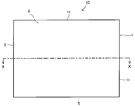
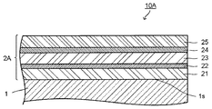
- FIG. 1A It is a front view which shows a glass plate with a laminated film schematically. It is sectional drawing in the XX line of the glass plate with a laminated film shown to FIG. 1A. It is sectional drawing which shows an example of a multilayer glass. It is sectional drawing of one Embodiment of the glass plate with a laminated film. It is sectional drawing which shows the modification of one Embodiment of the glass plate with a laminated film.
- FIGS. 1A and 1B are a front view schematically showing a laminated film-coated glass plate according to an embodiment of the present invention and a sectional view taken along line XX.
- a glass plate 10 with a laminated film according to an embodiment of the present invention shown in FIGS. 1A and 1B has a reinforced glass plate 1 and a laminated film 2 provided on one main surface 1 s of the glass plate 1.
- the glass plate 1 has a main surface 1s having a rectangular shape and four end surfaces 1t.
- the laminated film 2 is not provided on the end surface 1 t of the glass plate 1.
- up to two of the four end faces may have a laminated film.
- the laminated film 2 can impart the following properties (1-a) to (3-a) to the multilayer glass when it is used to produce a multilayer glass having the following specific configuration. It is a low emissivity laminated film.
- the multilayer glass for evaluating the laminated film is a glass plate with a laminated film for testing by forming the laminated film on one main surface of a first transparent glass plate having a thickness of 5 mm.
- a laminated film surface of the glass sheet with a test laminated film is the second transparent glass through a spacer disposed on the periphery of a glass sheet with the laminated film and a second transparent glass plate having a thickness of 6 mm. It is made to be spaced so as to face one main surface of the plate, and to have an air layer having a thickness of 12 mm between the glass plate with a laminated film for test and the second transparent glass plate.
- the multilayer glass thus produced has the following properties (1-a), (2-a) and (3-a).
- the glass plate 1 is not particularly limited as long as the reinforced main surface is a rectangular plate-like glass.
- the glass plate 1 is manufactured by a window glass for buildings, a commonly used float glass, or a roll-out method.
- a glass plate having inorganic transparency such as soda-lime glass can be used.
- the glass plate strengthening method includes air cooling strengthening, chemical strengthening, etc., and the glass plate 1 is preferably a glass plate strengthened by air cooling.
- the glass plate 1 may be strengthened before the laminated film 2 is provided on the main surface, and as described later, a non-heat treated product in which the laminated film is formed on the main surface of the glass plate is heat-treated at the time of manufacture. It is good also as the glass plate 1 strengthened by air-cooling. The latter is preferred in embodiments of the present invention.
- the glass plate 1 is appropriately selected according to the performance required as the glass plate 10 with a laminated film.
- the glass plate 1 is preferably a colorless glass such as a transparent glass or a high-transmission glass. . Further, colorless glass is preferable from the viewpoint of obtaining high color rendering properties.
- the glass plate 1 various glasses such as borosilicate glass, low expansion glass, zero expansion glass, low expansion crystallized glass, and zero expansion crystallized glass can be used.
- the thickness of the glass plate 1 is not necessarily limited, but is preferably a thickness that can secure a sufficient mechanical strength while maintaining the visible light transmittance of the glass plate 1 at a certain level or more, for example, 0.5 to 20 mm is preferable. is there.
- the shape of the glass plate 1 is not particularly limited as long as it is a plate shape and has a pair of rectangular main surfaces.
- the flat plate shape in which the pair of main surfaces are flat surfaces or the curved plate shape in which the entire or part of the pair of main surfaces has a curvature may be used.
- the main surface is rectangular means that the main surface has a substantially rectangular shape.
- a glass plate obtained by cutting off the corners of the peripheral portion is included in the category.
- the laminated film 2 is provided over the entire surface on the main surface 1 s of the glass plate 1, but is not provided on the four end surfaces 1 t of the glass plate 1.
- one or two of the four end faces of the glass plate may have a laminated film, but it is preferable that no laminated film is provided on any of the four end faces. .
- FIG. 2 shows a cross-sectional view of an example of the multilayer glass of the embodiment of the present invention using the laminated film-attached glass plate 10 as a constituent member.
- the multi-layer glass 3 is composed of a glass plate 10 with a laminated film having a first transparent glass plate 1 and a laminated film 2 and a second transparent glass plate 32 via a spacer 33 disposed on the periphery thereof. It is the structure separated so that it may have the intermediate
- the laminated film 2 surface of the laminated film-attached glass plate 10 is spaced so as to face one main surface of the second transparent glass plate 32.
- the laminated film is not provided on two or more end faces of the glass sheet, preferably all the end faces, it is fitted into a window of a building or the like. It is preferable because there is an effect of suppressing deterioration of the laminated film by a material containing a plasticizer, such as a setting block and a glazing channel, and an effect of suppressing a decrease in adhesive strength of the meshed glass with a rust preventive material.
- the laminated film 2 has a low emissivity that satisfies all of the above (1-a) to (3-a) when evaluated as a multilayer glass for evaluation of the specific configuration. It is a laminated film.
- the laminated film 2 is, for example, a multi-layer glass having a configuration similar to that shown in FIG. 2, the intermediate layer 34 is an air layer, the thickness t1 of the first transparent glass plate 1, and the second transparent glass.
- the plate thickness t2 of the plate 32 and the thickness t3 of the intermediate layer (air layer) 34 can be evaluated by a multi-layer glass (hereinafter referred to as “multi-layer glass 30”) of 5 mm, 6 mm, and 12 mm, respectively.
- multi-layer glass 30 multi-layer glass
- the transparent glass plate 1 having a thickness of 5 mm on which the laminated film 2 to be evaluated is provided is referred to as “a glass plate 10x with a laminated film for test”.
- the transparent glass plate used for the above evaluation and the like in this specification has a visible light transmittance of 80% or more measured in accordance with ISO 9050: 2003 regardless of the thickness, and is defined in ISO 9050: 2003.
- the CIE 1976L * a * b * chromaticity coordinates of the transmitted light obtained by irradiating visible light is glass whose absolute values of a * and b * are both 5 or less.
- the visible light transmittance measured in conformity with ISO 9050: 2003 is denoted as “Tv” and the visible light reflectance is denoted as “Rv” as necessary.
- the transmitted light obtained by irradiating visible light defined by ISO 9050: 2003 is also simply referred to as “transmitted light”
- the reflected light obtained by irradiating visible light defined by ISO 9050: 2003 is similarly Also simply called “reflected light”.
- CIE1976L * a * b * b * and a * based on chromaticity coordinates are also simply referred to as “b * ” and “a * ”, respectively.
- the characteristics of the laminated film in the glass plate with laminated film of the embodiment evaluated using the multilayer glass for evaluation for example, the multilayer glass 30 will be described.
- the laminated film-attached glass plate is usually prepared so as to face the other glass plate with a gap between the laminated film and the laminated film.
- the attached glass plate side is exposed to the outdoors, and the opposite glass plate side is used indoors.
- the evaluation using the multilayer glass 30 is an evaluation assuming such use.
- the solar heat gain rate (g value) is 0.265 or less.
- the solar heat gain rate (g value) is preferably 0.257 or less.
- the solar heat acquisition rate (g value) is on the second transparent glass plate 32 side (indoor side) when the solar energy incident from the glass plate 10x side (outdoor side) with the test laminated film is taken as 1. It is a value indicating the ratio of the amount of heat flowing in. From the solar heat acquisition rate (g value), it is possible to know the degree of heat shielding, that is, how much heat generated by sunlight (sun heat) is blocked.
- the solar heat acquisition rate is the heat that directly permeates the solar energy incident from the glass plate with test laminated film 10x side (outdoor side) (hereinafter also referred to as “transmitted heat”) and is absorbed after that. This is the ratio of the total amount of heat with the heat released to the glass plate 32 side (inside the room) (hereinafter also referred to as “radiant heat”).
- the solar heat acquisition rate is represented by a number between 0 and 1.
- the solar heat gain rate can be calculated by measuring the spectral characteristics and emissivity of the multilayer glass 30 and introducing them into a predetermined calculation formula. The smaller the solar heat acquisition rate, the smaller the ratio of the total heat quantity of the transmitted heat and the radiant heat to the solar heat quantity incident from the glass film 10x side with the laminated film for testing in the multilayer glass 30.
- the transmitted light obtained by irradiating visible light specified in ISO 9050: 2003 has a b * of 1 according to CIE1976L * a * b * chromaticity coordinates. It is as follows.
- the transmitted light is transmitted light that enters the glass plate 10x side (outdoor side) with the laminated glass 30 for test of the multilayer glass 30 and transmits to the second transparent glass plate 32 side (indoor side), the multilayer glass 30
- the transmitted light that is incident from the second transparent glass plate 32 side (indoor side) 30 and transmitted to the glass plate with test laminated film 10x side (outdoor side). May be used.
- the b * of the light transmitted through the multilayer glass 30 is preferably b * ⁇ 0. If b * of the transmitted light is within the above-mentioned range in the multi-layer glass 30, when the sunlight incident from the glass plate with test laminated film 10x side (outdoor side) hits a blind installed indoors, yellow It does not have a shabby color.
- the visible light reflectance on the glass plate with test multilayer film 10x side measured in accordance with (3-a) ISO 9050: 2003 is 20% or less.
- the visible light reflectance on the glass plate 10x side with a test laminated film measured in accordance with ISO 9050: 2003 is also referred to as Rv out .
- Rv out is preferably 18% or less. If Rv out is in the above range in the multilayer glass 30, reflection is not too high when the glass is viewed from the outdoor side, and the appearance is excellent in design.
- the multilayer glass 30 using the laminated film 2 has the following characteristics (1-a), (2-a), and (3-a), and further has the following (4-a), ( It preferably has one or more properties selected from 5-a), (6-a), (7-a) and (8-a). It is more preferable to have all the characteristics (4-a) to (8-a).
- the visible light reflectance on the front side of the second transparent glass plate 32 measured in accordance with ISO 9050: 2003 is also referred to as Rv in .
- Rv in the above preferably 20% or less as (4-a), more preferably 18% or less, and particularly preferably 16%. Since the double-glazed glass 30 has the characteristic (4-a), it is possible to suppress reflection in the room due to reflected light on the second transparent glass plate 32 side (indoor side).
- the difference between Rv out and Rv in is preferably 10% or less, more preferably 9% or less, and particularly preferably 8% or less, as described in (5-a) above.
- the difference Rv out and Rv in refers to a value obtained by subtracting one value from having a large value of Rv out and Rv in small. Since the double-glazed glass 30 has the characteristic (5-a), it is easy to adjust the color tone with excellent design properties on both the outdoor side and the indoor side.
- the CIE1976L * a * b * chromaticity coordinate a * and b * in the reflected light on the test laminated glass plate 10x side and the reflected light on the second transparent glass plate 32 side are as described in (6-a) above. Is preferably 2 or less. Since the double-glazed glass 30 has the above-mentioned characteristics (6-a), the red light of the reflected light on both the glass plate with test laminated film 10x side (outdoor side) and the second transparent glass plate 32 side (indoor side). , And yellowishness can be suppressed.
- the a * of the reflected light on the glass plate with test laminated film 10x side (outdoor side) is more preferably ⁇ 20 to 1, and particularly preferably ⁇ 15 to 0.
- the b * of the reflected light on the glass plate with test laminated film 10x side (outdoor side) is more preferably ⁇ 30 to 1, and particularly preferably ⁇ 25 to 0.
- the a * of the reflected light on the second transparent glass plate 32 side (inside the room) is more preferably ⁇ 20 to 1, and particularly preferably ⁇ 15 to 0.
- the b * of the reflected light on the second transparent glass plate 32 side (inside the room) is more preferably ⁇ 30 to 1, and particularly preferably ⁇ 25 to 0.
- the Tv of the multilayer glass 30 is preferably 30% or more as described above (7-a). Since the double-glazed glass 30 has the characteristic (7-a), the lighting in the building can be sufficient.
- the Tv of the multilayer glass 30 is preferably 60% or less from the viewpoint of antiglare properties.
- the Tv of the multilayer glass 30 is particularly preferably 35 to 55%.
- the color rendering properties of the transmitted light evaluated by the average color rendering index (Ra) using a D65 light source in accordance with JIS Z8726 (1990) of the multilayer glass 30 is 85% or more as described in (8-a) above. is there.
- the color rendering property according to (8-a) is 85% or more, the appearance when the double glazing 30 is viewed from the outside of the building becomes a natural intermediate color.
- the color rendering property is preferably 87% or more, and more preferably 90% or more.
- each of the glass plate with a laminated film for test used above and the structure of the multilayer glass using the same is a structure for evaluating the laminated film of the glass sheet with a laminated film of the embodiment, and is a laminate of the present invention.
- the structure of the film-attached glass plate is not limited to the structure of the test laminated film-attached glass plate.
- the use of the laminated film-attached glass plate of the present invention is not limited to the multilayer glass, and the configuration of the multilayer glass of the embodiment of the present invention is the configuration of the multilayer glass for the evaluation. It is not limited.
- the glass plate with a laminated film of the embodiment of the present invention preferably has a haze value of 2% or less in order to ensure transparency.
- the haze value of the laminated film-attached glass plate is more preferably 1% or less.
- the haze value of the glass plate is usually about 0.0 to 0.1%, and the haze value of the whole glass plate with a laminated film depends largely on the haze value of the laminated film. That is, the laminated film must have the characteristics satisfying (1-a), (2-a) and (3-a) in the above evaluation, and can be selected from (4-a) to (8-a).
- the laminated film has a haze value of 2% or less when a glass plate with a laminated film is obtained.
- the precursor of the laminated film-attached glass plate may be heat-treated at, for example, 600 ° C. or more to obtain the laminated film-attached glass plate of the embodiment. . That is, by heat-treating a glass plate to, for example, 600 ° C. or more, a laminated film is formed on one main surface as an air-cooled tempered glass plate or a curved glass plate to obtain a laminated film-attached glass plate.
- a curved glass plate is a curved glass plate reinforced by heat treatment.
- the constituent material of the laminated film is selected as described below so that the heat-treated laminated film has a haze value of 2% or less of the laminated film-attached glass plate.
- the laminated film-attached glass plate of the embodiment has a diameter observed in a range of 100 mm ⁇ 100 mm on the surface of the laminated film after a moisture resistance test in which the laminated film-attached glass plate is stored at 50 ° C. and 90% RH for 2 weeks.
- the number of white spots of 0.5 mm or more is preferably 5 or less. If the surface of the laminated film after the moisture resistance test satisfies the above conditions, for example, when producing a multi-layer glass using the laminated film-attached glass plate of the embodiment, sufficient moisture resistance when storing the laminated film-attached glass plate It can be said that it has sex.
- the structure of the laminated film in the glass plate with laminated film of the embodiment is not particularly limited as long as it has characteristics satisfying (1-a), (2-a), and (3-a) in the above evaluation.
- Examples of the laminated film that can satisfy the characteristics (1-a), (2-a), and (3-a) in the above evaluation include a laminated film (X) or a laminated film (Y) having the following configuration. .
- the laminated film (X) has n layers (n is an integer of 2 or more) of metal layers containing silver as a main component, and n + 1 dielectric layers laminated so as to sandwich the metal layer,
- the first metal layer closest to the glass plate is 6% by mass of at least one metal selected from palladium, gold, chromium, cobalt and nickel with respect to the total amount of silver and the metal. It contains in the above ratio. However, when the ratio of the metal to the total amount of silver and the metal is 6% by mass or more and less than 9% by mass, between the first metal layer and the second metal layer second closest to the glass plate.
- the dielectric layer has a thickness of 100 nm or less.
- the dielectric between the first metal layer and the second metal layer second closest to the glass plate The thickness of the layer is not particularly limited. In the present specification, the thicknesses of the metal layer, dielectric layer, and other layers constituting the laminated film represent geometric thicknesses.
- the laminated film (Y) has n layers (n is an integer of 2 or more) of metal layers containing silver as a main component and n + 1 dielectric layers laminated so as to sandwich the metal layer.
- the first metal layer closest to the glass plate among the metal layers is composed of at least one metal selected from palladium, gold, chromium, cobalt, and nickel, silver and the metal.
- the laminated film (Y) includes the dielectric layer between the first metal layer and the second metal layer second closest to the glass plate while the configuration of the n metal layers satisfies the above-described condition. Is 95 nm or less.
- the metal layer of the laminated film (X) and the laminated film (Y) that is a metal layer containing silver as a main component (n is an integer of 2 or more) plays a role of imparting low radiation to the laminated film. is there.
- containing a certain component as a main component means that the ratio of the component contained as a main component with respect to all the structural components exceeds 50 mass%.
- at least one metal selected from palladium, gold, chromium, cobalt and nickel is used as the specific metal layer in the metal layer containing n layers of silver as a main component.
- the first metal layer closest to the glass plate and the second closest one are essential as necessary in the laminated body (Y).
- the thickness of the dielectric layer between the second metal layer within the above range, all the characteristics of (1-a), (2-a) and (3-a) can be achieved in the above evaluation. It is said.
- the number of metal layers containing silver as a main component may be 2 or more, preferably 2 to 4, more preferably 2 or 3, and particularly preferably 2.
- FIG. 3 is a cross-sectional view of an embodiment of a laminated film-attached glass plate 10A having a laminated film in which the number of metal layers containing silver as a main component is 2 as the laminated film (X).
- the laminated film-attached glass plate 10 ⁇ / b> A has a laminated film 2 ⁇ / b> A on one main surface 1 s of the glass plate 1.
- the laminated film 2A includes a first dielectric layer 21, a first metal layer 22, a second dielectric layer 23, a second metal layer 24, and a third dielectric layer 25 in order from the glass plate 1 side.
- the first metal layer 22 and the second metal layer 24 are both metal layers containing silver as a main component.
- the first metal layer 22 contains at least one metal selected from palladium, gold, chromium, cobalt and nickel in a proportion of 6% by mass or more based on the total amount of silver and the metal.
- the thickness of the second dielectric layer 23 in between is 100 nm or less.
- the thickness of the second dielectric layer 23 is not particularly limited.
- the side close to the glass plate 1 is called “glass plate side”, and the opposite side is called “surface side”.
- the first metal layer 22 contains silver as a main component, and in addition to silver as a main component, at least one metal selected from palladium, gold, chromium, cobalt, and nickel is a total amount of silver and the metal. It contains in the ratio of 6 mass% or more with respect to.
- at least one metal selected from palladium, gold, chromium, cobalt, and nickel is also referred to as a metal M.
- the ratio (mass%) of the metal M with respect to the total amount of silver and the metal M is called content of the metal M.
- content of the metal M in the 1st metal layer 22 7.5 mass% or more is more preferable, and 9 mass% or more is especially preferable.
- the upper limit of the content of the metal M in the first metal layer 22 is preferably about 30% by mass from the balance between effect and economy.
- the metal M one selected from palladium, gold, chromium, cobalt and nickel may be used alone, or two or more may be used in combination. Among these, as the metal M, palladium and gold are preferable, and palladium is particularly preferable.
- the metal M is a metal that easily forms a solid solution with silver, which is the main material of the first metal layer 22. By using the metal M, the haze value of the laminated film 2A obtained by the heat treatment does not greatly increase even if the heat treatment is performed in the strengthening process or bending process of the glass plate.
- the first metal layer 22 can contain additive elements other than silver and metal M.
- the additive element include metal elements such as copper and titanium.
- the total content of the additive element is preferably 5% by mass or less, more preferably 3% by mass or less, and more preferably 1% by mass or less in all the components constituting the first metal layer 22. preferable.
- the second metal layer 24 is not particularly limited as long as it is a metal layer containing silver as a main component.
- the second metal layer 24 may contain the same metal M as that of the first metal layer 22 as necessary.
- a preferred embodiment of the metal M is the same as that of the first metal layer 22.
- about content of the metal M in case the 2nd metal layer 24 contains the metal M it depends on the performance calculated
- the ratio of the thickness of the second metal layer 24 to the thickness of the first metal layer 22 is 0.8 to 1.6. It is preferable that it exists in the range.
- the ratio value of the two metal layers is more preferably 0.85 to 1.5, and particularly preferably 0.9 to 1.4.
- the thickness of the first metal layer 22 is preferably 8 to 25 nm, and more preferably 10 to 20 nm.
- the thickness of the second metal layer 24 is preferably 10 to 30 nm, more preferably 12 to 25 nm after satisfying the value of the above ratio.
- the metal layer is sandwiched between laminated films each having a metal layer containing silver as a main component.
- a dielectric layer generally used in the form can be used without particular limitation. Specifically, a dielectric layer containing oxides, nitrides, oxynitrides or the like of metals or elements that can be formed on the glass plate 1, the first metal layer 22, or the second metal layer 24 is provided. Can be mentioned. Examples of the metal and element include zinc, tin, titanium, silicon, aluminum, chromium, nickel, niobium, and alloys thereof.
- metals and elements for example, tin, aluminum, chromium, titanium, silicon, boron, magnesium, gallium are included in the metal and element oxides, nitrides, oxynitrides, and the like constituting the dielectric layer.
- An element selected from the above may be doped in the form of an oxide, nitride, or oxynitride.
- the nitride layer and the oxynitride layer have a large stress change due to the heat treatment, and the stress accumulated in the film by the heat treatment causes the stability of the metal layer to be lost.
- the structure which does not have a nitride layer or an oxynitride layer between the metal layer nearest to the laminated film surface among the said metal layers and a glass plate is preferable.
- at least the first dielectric layer 21 and the second dielectric layer 23 are preferably neither a nitride layer nor an oxynitride layer from the viewpoint of film formation efficiency. More preferably, all of the first dielectric layer 21, the second dielectric layer 23, and the third dielectric layer 25 are preferably oxide layers.
- the first dielectric layer 21, the second dielectric layer 23, and the third dielectric layer 25 include a first metal layer 22 containing silver as a main component, a second dielectric layer 25, and a second dielectric layer 25. Since the metal layer 24 is sandwiched, the metal layers 22 and 24 can be made homogeneous and dense, and a dielectric layer capable of improving adhesion to the metal layers 22 and 24, for example, containing an oxide of zinc A dielectric layer is preferred.
- oxide constituent elements other than zinc can be contained.
- oxide constituent elements other than zinc include tin, aluminum, chromium, titanium, silicon, boron, magnesium, and gallium, and these can contain one or more.
- Tin, aluminum, chromium, titanium, silicon, boron, magnesium, and gallium which are oxide constituent elements other than zinc, are included in the dielectric layers 21, 23, and 25, for example, tin oxide (SnO 2 ), aluminum oxide (Al 2 ). O 3 ), chromium oxide (Cr 2 O 3 ), titanium oxide (TiO 2 ), silicon oxide (SiO 2 ), boron oxide (B 2 O 3 ), magnesium oxide (MgO), gallium oxide (Ga 2 O 3 ) Or as a composite oxide thereof.
- oxide constituent elements other than zinc aluminum and tin are preferable because they are inexpensive.
- Aluminum is preferable because it is an inexpensive material and can increase the deposition rate. Tin is also preferable because it is a relatively inexpensive material.
- an oxide constituent element other than zinc in the dielectric layer containing zinc oxide, in the total amount (in 100 mass%) of zinc and oxide constituent elements other than zinc (excluding oxygen), zinc It is preferable that the oxide constituting elements other than 1 to 50% by mass. Visible light transmittance can be effectively improved by making the ratio of oxide constituent elements other than zinc into 1 mass% or more. Moreover, stability of the metal layers 22 and 24 formed between the dielectric layers 21, 23, and 25 can be ensured by setting the ratio of oxide constituent elements other than zinc to 50 mass% or less.
- the thicknesses of the first to third dielectric layers 21, 23, and 25 are not necessarily limited. It is not a thing.
- the thicknesses of the first and third dielectric layers 21 and 25 are each preferably 10 to 50 nm and more preferably 20 to 45 nm.
- the thickness of the second dielectric layer 23 sandwiched between the first metal layer 22 and the second metal layer 24 is thicker than the thickness of the first and third dielectric layers 21 and 25. 60 to 120 nm is preferable, and 70 to 110 nm is more preferable.
- the content of the metal M in the first metal layer 22 is set to 9% by mass or more, and the thicknesses of the dielectric layers 21, 23, and 25 are set in the above ranges, whereby the visible light reflectance is increased. Can be made lower and a good reflection color tone can be realized.
- the thickness of the second dielectric layer 23 is 100 nm or less.
- the thickness of the second dielectric layer 23 is preferably 60 to 100 nm, and more preferably 70 to 100 nm.
- the thicknesses of the first dielectric layer 21 and the third dielectric layer 25 are not necessarily limited, but both are preferably thinner than the thickness of the second dielectric layer 23. Specifically, the thickness of the first dielectric layer 21 and the third dielectric layer 25 is the first dielectric when the content of the metal M in the first metal layer 22 is 9% by mass or more.
- the thickness can be the same as that of the body layer 21 and the third dielectric layer 25.
- the content of the metal M in the first metal layer 22 is 6 mass% or more and less than 9 mass%, and the thickness of the dielectric layers 21, 23, 25 is in the above range, Visible light reflectance can be further lowered, and a good reflection color tone can be realized.
- the laminated film (Y) may have two or more metal layers containing silver as a main component, preferably 2 to 4, more preferably 2 or 3, 2 is particularly preferred.
- the content of the metal M is 1.5% by mass or more in any metal layer, and the total content of the metal M in each layer is 4%. It is at least mass%.
- the number of metal layers containing silver as a main component is 3 or more, at least one of the metal layers closest to the glass plate and the remaining metal layers has a ratio of 1.5% by mass or more of metal M.
- the total content of metal M in each layer is 4% by mass or more.
- the content of the metal M may be the same or different in each metal layer.
- the more preferable content of the metal M in each metal layer is 4% by mass or more and particularly preferably 7% by mass or more in the metal layer closest to the glass plate. Furthermore, in the other metal layer containing 1.5% by mass or more of metal M, the content of metal M is more preferably 2% by mass or more, and particularly preferably 2.5% by mass or more. In the metal layer in which the content of the metal M is not specified, the metal M may or may not be contained. When the metal M is contained, the content is preferably 1.5% by mass or more. The upper limit of the content of the metal M in each metal layer is preferably about 20% by mass.
- the laminated structure in the laminated film (Y) for example, the same laminated structure as the laminated film 2A of the laminated film 10A shown in FIG. 3, that is, the first dielectric layer, And a structure having a second metal layer, a second dielectric layer, a second metal layer, and a third dielectric layer.
- the laminated film (Y) is the same as the laminated film (X) except that the metal layer is different in the content of the metal M in the first metal layer and the second metal layer. A configuration is preferred.
- the dielectric film is the laminated film (X) except that the thickness of the second dielectric layer is different.
- the thickness of the second dielectric layer sandwiched between the first metal layer and the second metal layer is 95 nm or less.
- the thickness of the second dielectric layer is preferably 60 to 95 nm, and more preferably 70 to 95 nm.
- the thicknesses of the first dielectric layer and the third dielectric layer are not necessarily limited, but both are preferably thinner than the thickness of the second dielectric layer.
- the thicknesses of the first dielectric layer and the third dielectric layer can be made similar to the thicknesses of the first dielectric layer and the third dielectric layer in the laminated film (X).
- the metal layer is configured as described above, and the thickness of the dielectric layer is set in the above range, whereby the visible light reflectance can be further lowered and a good reflection color tone can be realized. Can do.
- the laminated film when the number of metal layers containing silver as a main component is 2, the laminated film (X) wherein the content of the metal M in the first metal layer close to the glass plate is 6% by mass or more. Even so, the content of the metal M in the first metal layer close to the glass plate and the second metal layer far from the glass plate is 1.5% by mass or more, and the content of the metal M in each layer Even if it is the said laminated film (Y) whose sum total is 4 mass% or more, it is preferable that a laminated film is a layer structure which shows a cross section in FIG.
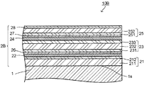
- FIG. 4 is a cross-sectional view showing a modification of one embodiment of the laminated film-attached glass plate.
- the laminated film-attached glass plate 10 ⁇ / b> B has a laminated film 2 ⁇ / b> B on one main surface 1 s of the glass plate 1.
- the laminated film 2B includes, in order from the glass plate 1, the first dielectric layer 21, the first metal layer 22, the first barrier layer 26, the second dielectric layer 23, the second metal layer 24, Two barrier layers 27, a third dielectric layer 25, and a protective layer 28.
- Both the first metal layer 22 and the second metal layer 24 can be the same as the first metal layer 22 and the second metal layer 24 of the laminated film 2A in the laminated film-attached glass plate 10A.
- the first dielectric layer 21 includes a first amorphous dielectric layer 211 and a first crystalline dielectric layer 212 from the glass plate side.
- the second dielectric layer 23 includes a second crystalline dielectric layer 231, a second amorphous dielectric layer 232, and a third crystalline dielectric layer 233 from the glass plate side.
- the third dielectric layer 25 includes a fourth crystalline dielectric layer 251 and a third amorphous dielectric layer 252 from the glass plate side.
- the first, second, and third dielectric layers 21, 23, and 25 have the crystalline dielectric layer and the amorphous dielectric layer, respectively, and sandwich the first metal layer 22 therebetween.
- the third crystalline dielectric layer 233 and the fourth crystalline dielectric layer are arranged such that the first crystalline dielectric layer 212 and the second crystalline dielectric layer 231 sandwich the second metal layer 24 therebetween.
- 251 is arranged, and first, second, and third amorphous dielectric layers 211, 232, and 252 are arranged on both sides thereof.
- the total thickness of each layer constituting the first dielectric layer 21, that is, the thickness of the first dielectric layer 21 is the case of either the laminated film (X) or the laminated film (Y).
- the thickness can be the same as the thickness of the laminated film (X) and the laminated film (Y) in the laminated film 2A.
- the laminated film 2B has a first barrier layer 26 and a second barrier layer 27 on the surface side of the first metal layer 22 and the second metal layer 24 so as to be in contact with the metal layers, respectively.
- the protective layer 28 is provided on the surface side of the third dielectric layer 25 on the surface side.
- the laminated film in the laminated film-attached glass plate of the embodiment preferably has no nitride layer or oxynitride layer between the metal layer closest to the laminated film surface and the glass plate among the metal layers.
- the laminated film 2B at least the first dielectric layer 21, the first barrier layer 26, and the second dielectric layer 23 are neither a nitride layer nor an oxynitride layer from the viewpoint of film formation efficiency. It is preferable. More preferably, the first dielectric layer 21, the first barrier layer 26, the second dielectric layer 23, the second barrier layer 27, and the third dielectric layer 25 are all oxide layers. Is preferred.
- the first to fourth crystalline dielectric layers 212, 231, 233, and 251 are arranged so as to sandwich the first and second metal layers 22 and 24 as described above, and are highly crystalline dielectric layers. It is.
- the crystalline dielectric layer can be made dense by making the first metal layer 22 and the second metal layer 24 formed therebetween uniform by crystallization or the like.
- a dielectric material having a high crystallinity among the dielectric materials described above as materials constituting the dielectric layers 21, 23, and 25 in the laminated film 2A A material can be appropriately selected and used.
- a dielectric material having high crystallinity specifically, an oxide of zinc or zinc containing an oxide constituent element other than zinc such as aluminum, titanium, tin, or the like. Oxides are preferred.
- an oxide of zinc containing aluminum is particularly preferable in terms of crystallinity, film formation rate, and economy.
- aluminum is contained in the oxide of zinc, it is contained in the form of aluminum oxide (Al 2 O 3 ) or a composite oxide of zinc and aluminum as described above.
- the content of aluminum in the zinc oxide containing aluminum is preferably 1 to 10% by mass of aluminum in the total amount of zinc and aluminum (in 100% by mass), preferably 1 to 5% by mass. It is more preferable.
- each of the first to fourth crystalline dielectric layers 212, 231, 233, and 251 is preferably 3 to 15 nm independently. By setting the thickness of the crystalline dielectric layers 212, 231, 233, and 251 to 3 nm or more, crystallization can be promoted, and the first and second metal layers 22 and 24 formed therebetween are made homogeneous. It can be precise. If the thickness of the crystalline dielectric layers 212, 231, 233, and 251 is 15 nm, it is sufficient for promoting crystallization. By making the thickness less than this, the crystalline dielectric layers 212, 231, 233 are reduced. , 251 can be prevented from deteriorating the characteristics of the first and second metal layers 22 and 24 due to the rough surface.
- the thickness of the crystalline dielectric layers 212, 231, 233, and 251 is 5 from the viewpoint of making the first and second metal layers 22 and 24 more homogeneous and dense, and having excellent characteristics. More preferably, it is ⁇ 11 nm.
- a first barrier layer 26 and a second barrier layer 27 are disposed on the surface side of the first and second metal layers 22 and 24 so as to be in contact with the metal layers, respectively. Therefore, the second crystalline dielectric layer disposed on the surface side of the first and second metal layers 22, 24 among the first to fourth crystalline dielectric layers 212, 231, 233, 251. 231 and the fourth crystalline dielectric layer 251 are arranged on the surface side of the first and second metal layers 22 and 24 with the first barrier layer 26 and the second barrier layer 27 interposed therebetween.
- the function of making the first and second metal layers 22 and 24 homogeneous and dense is that the first crystal disposed on the glass plate side of the first and second metal layers 22 and 24 This can be sufficiently achieved by using the conductive dielectric layer 212 and the third crystalline dielectric layer 233 together.
- the first, second, and third amorphous dielectric layers 211, 232, and 252 are first to fourth crystalline dielectric layers 212 provided so as to sandwich the first and second metal layers 22 and 24, respectively. , 231, 233, 251, or an amorphous dielectric layer disposed above and below. Since the amorphous dielectric layer does not grow crystal grains, it is possible to ensure the flatness of the entire laminated film 2B by providing the amorphous dielectric layer between or above and below the crystalline dielectric layer.
- an amorphous dielectric material is appropriately selected from the above-described dielectric materials as materials constituting the dielectric layers 21, 23, 25, etc. in the laminated film 2A. It can be selected and used.
- an amorphous dielectric material specifically, an oxide of zinc containing 10% by mass or more of an oxide constituent element other than zinc, such as tin, aluminum, titanium, etc. Etc. are preferred.
- zinc oxide containing tin is particularly preferable in terms of non-crystallinity and economy.
- tin is contained in the zinc oxide, it is contained in the form of tin oxide (SnO 2 ) or a composite oxide of zinc and tin as described above.
- the content of tin in the zinc oxide containing tin should be 20 to 80% by mass in the total amount of zinc and tin (in 100% by mass). The content is preferably 30 to 70% by mass.
- the thicknesses of the first, second and third amorphous dielectric layers 211, 232 and 252 are preferably 5 to 45 nm independently for the thicknesses of the first and third amorphous dielectric layers 211 and 252. 10 to 35 nm is more preferable. Further, regarding the thickness of the second amorphous dielectric layer 232 sandwiched between the second crystalline dielectric layer 231 and the third crystalline dielectric layer 233, the laminated film 2B has the laminated film (X), Considering whether it belongs to one of the laminated films (Y), the thickness of the second dielectric layer 23 is set to be within the thickness range in each case described above.
- the thickness of the second amorphous dielectric layer 232 is 30 to 30%. 100 nm is preferable, and 40 to 80 nm is more preferable.
- the thickness of the second amorphous dielectric layer 232 Is preferably 50 to 90 nm, more preferably 60 to 90 nm.
- the thickness of the second amorphous dielectric layer 232 is preferably 50 to 85 nm, and more preferably 60 to 85 nm.
- the visible light transmittance is increased while ensuring the flatness of the entire laminated film 2B.
- the film formation time can be shortened appropriately and the productivity can be improved.
- the first barrier layer 26 and the second barrier layer 27 are the first metal layer 22 and the second barrier layer 27, respectively, when the second crystalline dielectric layer 231 and the fourth crystalline dielectric layer 251 are formed. It is provided to suppress oxidation of the metal layer 24.
- the constituent materials of the first barrier layer 26 and the second barrier layer 27 are not particularly limited as long as they can suppress the oxidation.
- the constituent materials of the first and second barrier layers 26 and 27 include, for example, titanium, zinc aluminum alloy, nickel chrome alloy, or oxides thereof, and have a metal or stoichiometric composition. On the other hand, those made of an oxide deficient in oxygen can be mentioned.
- a metal or an oxide-deficient material for the stoichiometric composition the first metal layer 22 is oxidized during the formation of the second crystalline dielectric layer 231, and the fourth The oxidation of the second metal layer 24 during the formation of the crystalline dielectric layer 251 can be suppressed.
- the first and second barrier layers 26 and 27 are preferably composed mainly of titanium or an oxide of titanium.
- the thing which has an oxide of titanium as a main component is what contains 50 atomic% or more of titanium in the total amount (100 atomic%) of oxide constituent elements (except oxygen) other than titanium and titanium.
- the first and second barrier layers 26 and 27 can contain a constituent element other than titanium.
- constituent elements other than titanium include niobium, tantalum, zirconium, silicon, tungsten, and molybdenum, and these can contain one or more of them.
- Titanium, niobium, tantalum, tungsten, and molybdenum are included in the oxidation barrier layer, for example, TiO x (x ⁇ 2), Nb 2 O x (x ⁇ 5), Ta 2 O x (x ⁇ 5), ZrO x ( x ⁇ 2), SiO x (x ⁇ 2), WO x (x ⁇ 3), MoO x (x ⁇ 3), or a composite thereof.
- first and second barrier layers 26 and 27 contain constituent elements other than titanium
- titanium is included in the total amount (100 atomic%) of titanium and constituent elements other than titanium from the viewpoint of reducing material costs.
- the constituent elements other than are preferably 30 atomic percent or less, more preferably 20 atomic percent or less, and even more preferably 10 atomic percent or less.
- the first and second barrier layers 26 and 27 are preferably made of only titanium or an oxide of titanium, and particularly TiO x (1) which is an oxide deficient in oxygen with respect to the stoichiometric composition. ⁇ X ⁇ 2) is preferable.
- the first and second barrier layers 26 and 27 are partially or wholly oxidized when the second crystalline dielectric layer 231 and the fourth crystalline dielectric layer 251 are formed. Therefore, after the second crystalline dielectric layer 231 and the fourth crystalline dielectric layer 251 are formed, it is not always necessary to be made of an oxide deficient in oxygen with respect to the stoichiometric composition. It may be composed of an oxide layer having a stoichiometric composition formed by oxidation and an unoxidized layer remaining without being oxidized, or only an oxide layer having a stoichiometric composition formed by oxidation. It may be made up of.
- each of the first and second barrier layers 26 and 27 is preferably 1 nm or more independently. By setting the thickness of the first and second barrier layers 26 and 27 to 1 nm or more, the oxidation of the first metal layer 22 and the second metal layer 24 can be effectively suppressed.
- the thicknesses of the first and second barrier layers 26 and 27 are not particularly limited as long as they are 1 nm or more, but in order to suppress oxidation of the first metal layer 22 and the second metal layer 24. If it is less than 10 nm, the visible light transmittance can be effectively increased.
- the protective layer 28 has a function of improving the durability of the laminated film 2B, particularly the scratch resistance of the surface, and a function as a barrier against moisture and oxygen during heat treatment.
- the protective layer 28 is not particularly limited as long as it improves the above function.
- the protective layer 28 mainly composed of oxynitride such as titanium, silicon, or aluminum is preferable.
- a carbon layer containing carbon as a main component that can improve the scratch resistance from film formation to heat treatment may be provided on the outermost layer of the protective layer 28.
- the protective layer 28 is preferably a layer mainly composed of titanium oxide in advance.
- the thickness of the protective layer 28 is preferably 1 nm or more. When the thickness of the protective layer 28 is 1 nm or more, the durability is effectively improved. If the thickness of the protective layer 28 is 15 nm, it is sufficient for ensuring the durability, and by making it less than this, the productivity of the protective layer 28 is improved.
- the thickness of the protective layer 28 is more preferably 10 nm or less, and further preferably 6 nm or less.
- the respective layers constituting the laminated film are formed in that order on one principal surface of the glass plate having a larger principal surface than the laminated film-attached glass plate to be produced by a conventional method.
- the strengthening of the glass plate in the laminated film-attached glass plate is usually performed by air-cooling strengthening, and specifically by performing a heat treatment (heat treatment step) after laminating the respective layers.
- heat treatment step As an order of each process, it is essential that a cutting process is performed after a film-forming process.
- the order of the heat treatment steps is not limited, but it is preferable to perform the heat treatment after the cutting step.
- the film forming method is not particularly limited, and physical vapor deposition (vacuum vapor deposition, ion plating, sputtering), chemical vapor deposition (thermal CVD, plasma CVD, photo CVD), ion beam sputtering Etc. can be applied.
- physical vapor deposition vacuum vapor deposition, ion plating, sputtering
- chemical vapor deposition thermal CVD, plasma CVD, photo CVD
- ion beam sputtering Etc ion beam sputtering Etc.
- each layer will be described in detail by taking as an example the glass plate with laminated film 10A shown in FIG. 3 and the glass plate with laminated film 10B shown in FIG. 3 and 4 are shown in a state where they have already been cut, but in actuality, the film formation of each layer is larger than the glass plate with a laminated film to be manufactured.
- the film is formed on one main surface of the glass plate.
- the method for forming the first, second, and third dielectric layers 21, 23, and 25 in the laminated film 2A of the laminated glass plate 10A is not particularly limited.
- the film can be formed by selecting a sputtering target and an atmospheric gas corresponding to the constituent materials and performing sputtering by a conventional method.
- these dielectric layers are provided as, for example, metal oxide layers
- a metal target is used as a sputtering target, and film formation is performed by reactive sputtering in a sputtering gas with a sufficiently high oxidizing gas concentration. can do.
- the metal target for example, a metal target containing zinc is preferably used.
- the metal target containing zinc can contain oxide constituent elements other than zinc.
- oxide constituent elements other than zinc include tin, aluminum, chromium, titanium, silicon, boron, magnesium, and gallium, and these can contain one or more kinds.
- the oxide constituent element other than zinc is preferably 1 to 50 mass% in the total amount (100 mass%) of zinc and the oxide constituent element other than zinc. .
- the first to fourth crystalline dielectric layers 212, 231, 233, and 251 in the laminated film 2B of the laminated film glass plate 10B are formed as, for example, zinc oxide layers containing aluminum.
- reactive sputtering is performed using a metal target containing 1 to 10% by mass of aluminum in a desired ratio of zinc and aluminum, for example, in the total amount of zinc and aluminum (in 100% by mass).
- a film can be formed.
- the first, second, and third amorphous dielectric layers 211, 232, and 252 in the laminated film 2B of the laminated glass plate 10B are formed as, for example, zinc oxide layers containing tin.
- reactive sputtering is performed using a metal target containing 30 to 70% by mass of tin and zinc in a desired ratio, for example, in the total amount of zinc and tin (in 100% by mass).
- a film can be formed by performing.
- the method for forming the first metal layer 22 and the second metal layer 24 is not particularly limited.
- the first metal layer 22 and the second metal layer 24 contain, for example, silver as a main component as a sputtering target, and at least one metal M selected from palladium, gold, chromium, cobalt, and nickel is silver.
- Film formation can be performed by performing sputtering in an atmosphere containing only an inert gas such as argon, using a target that is contained in a predetermined ratio with respect to the total amount of metal and metal M.
- the sputter target used for forming the first metal layer 22 contains silver as a main component
- the metal M contains silver and metal.
- a target containing 6% by mass or more of the total amount with M is used, and the second metal layer 24 uses a target containing silver as a main component as a sputter target.
- the sputter target used for forming the first metal layer 22 and the second metal layer 24 are each independently a metal containing silver as a main component as a sputter target.
- M is contained in a ratio of 1.5% by mass or more with respect to the total amount of silver and metal M, and the content of metal M with respect to the total amount of silver and metal M in first metal layer 22 ( Mass%) and a target in which the total content (mass%) of metal M with respect to the total amount of silver and metal M in second metal layer 24 is 4 mass% or more is used.
- the first barrier layer 26 and the second barrier layer 27 are preferably formed by sputtering using a metal target such as titanium or a reducing oxide target and using an inert gas as a sputtering gas.
- the titanium oxynitride layer is formed, for example, as follows.
- the layer is obtained by heat treatment as described below.
- the titanium nitride layer can be formed by sputtering in a sputtering gas atmosphere made of a mixed gas of argon and nitrogen using a titanium target.
- the protective layer 28 has a carbon layer containing carbon as a main component, the carbon layer is sputtered in an atmosphere containing only an inert gas such as argon using a carbon target. And film formation may be performed.
- the glass plate with the laminated film is cut into a desired product shape.
- the laminated film is not provided in the end surface of 2 or more as for the glass plate with a laminated film of embodiment of this invention.
- the laminated film is also formed on the end face of the glass plate.
- a non-heat treated product of a laminated film-coated glass plate can be obtained.
- the non-heat treated product thus obtained is subjected to heat treatment to obtain the laminated film-attached glass plate of the embodiment, these are treated as precursors, and the laminated film-attached glass plate obtained by heat treatment is used in the present invention.
- the glass plate with the laminated film of the embodiment is used.
- the precursor of the glass sheet with a laminated film obtained above is used in a heating furnace according to the purpose, for example, for heating temperature or bending for strengthening.
- Heat at a heating temperature for a predetermined time For example, for the precursor of a glass plate with a laminated film using a float glass substrate as the glass plate, when performing air-cooling strengthening of the glass substrate, the heat treatment is performed as the surface temperature of the precursor of the glass plate with a laminated film. A temperature of 500 to 700 ° C. for 1 to 30 minutes is preferable.
- the following methods are known. Two types of metal targets containing silver and metal M are prepared so that the content of metal M is different. Metal obtained by laminating metal films having different metal M contents such that the film thickness and the content of metal M are the desired values as the finally obtained metal layer using the two types of targets obtained A layer precursor is obtained. By firing this precursor, a metal layer mainly composed of silver containing a predetermined amount of metal M is obtained as a single layer having a uniform composition.
- the other layers constituting the laminated film are formed in the same manner as described above, and when the metal layer is formed by such a method, the desired size is obtained after the film formation.
- a precursor of the laminated film-attached glass plate in which at least the metal layer is not in the final form is obtained.
- the surface temperature of the precursor of the glass sheet with a laminated film is 500 to 700 ° C. Firing conditions are preferred.
- the glass plate with a laminated film according to the embodiment of the present invention preferably has a haze value of 2% or less even when heat treatment is performed under a temperature condition of 600 ° C. or higher, for example, in the process of manufacturing.
- the use of the laminated film-attached glass plate of the embodiment of the present invention is not limited.
- it can be used as a constituent member of low-radiation laminated glass or multilayer glass. It is preferable to use it as a structural member of a double glazing.
- the laminated glass examples include laminated glass having a configuration in which two transparent substrates arranged opposite to each other sandwich an intermediate film and are bonded by the intermediate film.
- the glass plate with a laminated film of the embodiment can be used for one of such laminated glass transparent substrates.
- the laminated film is used by being disposed on the intermediate film side.
- the other transparent substrate is preferably a transparent glass plate.
- the laminated glass-attached glass plate side is used as an outdoor side.
- the laminated glass may have three or more transparent substrates.
- the multi-layer glass examples include a multi-layer glass having a configuration in which two transparent substrates arranged opposite to each other are sealed at the periphery thereof with a spacer and an intermediate layer is formed between the opposing transparent substrates.
- the glass plate with a laminated film of the embodiment can be used on one of the transparent substrates of such multilayer glass. In that case, the laminated film is disposed on the intermediate layer side.
- the other transparent substrate is preferably a transparent glass plate.
- the intermediate layer is preferably an air layer or an inert gas such as argon. When such a multi-layer glass is used as a window glass, it is used so that the glass plate side with a laminated film becomes the outdoor side.
- the multi-layer glass may have three or more transparent substrates.
- the multilayer glass of the embodiment of the present invention is configured by using the laminated film-attached glass plate of the embodiment on one of the transparent substrates of the multilayer glass and using the second transparent glass plate as the other transparent substrate.
- the FIG. 2 shows a cross-sectional view of an example of the multilayer glass of the embodiment of the present invention.
- the multi-layer glass 3 is an example in which the laminated film-attached glass plate 10 is used as a constituent member, and the laminated film 2 surface of the laminated film-attached glass plate 10 is opposed to one main surface of the second transparent glass plate 32. Are spaced apart.
- the multilayer glass 3 has an intermediate layer 34 between the laminated film-attached glass plate 10 and the second transparent glass plate 32 by spacers 33 arranged on the periphery.
- the multilayer glass of the embodiment of the present invention has the following properties (1-b), (2-b) and (3-b).
- (1-b) The solar heat acquisition rate (g value) on the second glass plate side with respect to the solar radiation from the laminated film-coated glass plate side measured in accordance with ISO 9050: 2003 is 0.265 or less. is there.
- (3-b) The visible light reflectance of the laminated film-attached glass plate side measured in accordance with ISO 9050: 2003 is 20% or less.
- the characteristics (1-b) to (3-b) are characteristics corresponding to (1-a) to (3-a) in the evaluation of the laminated film-attached glass plate of the embodiment of the present invention, respectively.
- the preferred range for (1-b) to (3-b) in the multilayer glass of the embodiment of the present invention is the same as the preferred range for (1-a) to (3-a).
- the multilayer glass of the embodiment of the present invention preferably has characteristics corresponding to (4-a) to (8-a) in the evaluation of the laminated film-coated glass plate of the embodiment of the present invention. A preferable range in these characteristics is more preferable.
- the transparent substrate with a laminated film is suitable for buildings, but is not necessarily limited to buildings, and can be used for vehicles such as automobiles to the extent applicable.
- Examples 1, 2, and 8 are examples, and examples 3 to 7 are comparative examples.
- Examples 1-8) As glass plates with laminated films, glass plates with laminated films 1 to 8 having the constitution shown in Table 1 were produced. That is, a soda-lime glass plate (Asahi Glass Co., Ltd. (FL5, FL6), 100 mm ⁇ 180 mm ⁇ 5 mmt, 100 mm ⁇ 180 mm ⁇ 6 mmt) was used as the glass plate, and the DC sputtering method was performed on one main surface by the following method. After forming the precursor of the laminated film by cutting, it is cut and fired to form each film so as to have the film configuration and thickness shown in Table 1, and laminated on one main surface of the glass plate A glass plate with a laminated film having a film and having no laminated film on four end faces was produced.
- a soda-lime glass plate As ahi Glass Co., Ltd. (FL5, FL6), 100 mm ⁇ 180 mm ⁇ 5 mmt, 100 mm ⁇ 180 mm ⁇ 6 mmt
- each film of the glass plate and the laminated film is described in the order of lamination from the left.
- Each film is indicated by a constituent material and a thickness indicated by a number in parentheses (the unit is all [nm]).
- the abbreviations of the constituent materials according to Examples 1 to 8 shown in Table 1 have the following meanings, and the thicknesses of the layers having no thickness indication are as follows.
- the laminated film-attached glass plates 1 to 8 are laminated film-attached glass plates having the same configuration as the laminated film-attached glass plate 10B whose cross section is shown in FIG.
- the layer thickness is 10 nm.
- AgPd layer in which palladium is doped in silver. In Table 1, the number after AgPd indicates the ratio (mass%) of palladium to the total amount of palladium and silver.
- TiOx a layer made of titanium oxide having a stoichiometric composition ratio or a non-stoichiometric composition ratio, or a layer thickness of 4 nm when no thickness is described.
- TiOxNy a layer composed of titanium oxynitride having a stoichiometric composition ratio or a non-stoichiometric composition ratio, and when there is no description of the thickness, the layer thickness is 3.5 nm.
- the in-line type sputtering apparatus used for sputtering contains a titanium target (Ti target), a target made of a zinc alloy containing 50% by mass of tin (SnZn alloy target), and 2% by mass of aluminum in the film forming chamber.
- a target made of a zinc alloy (AlZn alloy target), a silver target containing 1% by mass of palladium (AgPd1 target), and a silver target containing 30% by mass of palladium (AgPd30 target) were placed on the cathode. Then, the cleaned glass plate was introduced into the load lock chamber, and the entire inside of the vacuum chamber was evacuated to 2.0 ⁇ 10 ⁇ 4 Pa to form each layer as shown below.
- ⁇ SnZn oxide layer> Argon and oxygen were introduced into the vacuum chamber at 30:70 sccm as discharge gases, and formed by reactive DC magnetron sputtering using the SnZn alloy target described above.
- the sputtering target was 70 ⁇ 200 mm 2 and 500 W was applied as the sputtering power. At this time, the pressure in the vacuum chamber was 0.4 Pa.
- Oxygen was introduced into the vacuum chamber as a discharge gas at 100 sccm and formed by DC magnetron sputtering using the AlZn alloy target described above.
- the sputtering target was 70 ⁇ 200 mm 2 and 500 W was applied as the sputtering power. At this time, the pressure in the vacuum chamber was 0.4 Pa.
- the thickness of the AlZn oxide layer was all 10.0 nm.
- Argon was introduced into the vacuum chamber by 50 sccm as a discharge gas and formed by DC magnetron sputtering using the above AgPd1 target.
- the sputtering target was 70 ⁇ 200 mm 2 and 100 W was applied as the sputtering power.
- ⁇ AgPd layer> Argon was introduced into the vacuum chamber as a discharge gas by 50 sccm, and the above-described AgPd1 target and AgPd30 target were successively used in this order and formed by DC magnetron sputtering. In either case, the sputtering target was 70 ⁇ 200 mm 2 and 100 W was applied as the sputtering power.
- the continuously formed AgPd1 layer and AgPd30 layer are formed into a single AgPd layer by the following heat treatment (firing) after the production of the laminated film precursor on the glass plate, and the total thickness of each is determined as the final AgPd layer. The layer thickness was taken.
- Ti barrier layer> Argon was introduced into the vacuum chamber as a discharge gas at 100 sccm, and the magnet was formed by DC magnetron sputtering using the Ti target described above.
- the sputtering target was 70 ⁇ 200 mm 2 and 50 W was applied as the sputtering power. At this time, the pressure in the vacuum chamber was 0.4 Pa.
- the thickness of the Ti barrier layer was all 4.0 nm.
- the Ti barrier layer is a layer existing as a TiOx layer in the laminated film of the finally obtained glass plate with laminated film.
- TiNx layer Argon and nitrogen were introduced into the vacuum chamber at 70:30 sccm as discharge gases, and formed by DC magnetron sputtering using the Ti target described above.
- the sputtering target was 70 ⁇ 200 mm 2 and 500 W was applied as the sputtering power. At this time, the pressure in the vacuum chamber was 0.4 Pa.
- the thickness of the TiNx layer was all set to 3.5 nm.
- the TiNx layer is a layer present as a TiOxNy layer in the laminated film of the finally obtained glass plate with laminated film.
- the glass plate with the precursor of the laminated film obtained above is cut with a glass cutter so that the size of the main surface becomes a rectangular shape of 70 mm ⁇ 100 mm.
- the precursor examples 1 to 8 of the glass plates with laminated films having the laminated film precursors on the four end surfaces of the glass plates without the laminated film precursors were obtained.
- the glass plates with laminated films 1 to 8 obtained above were evaluated as follows.
- the multilayer glass using the laminated film-attached glass plates of Examples 1, 2, and 8 is the multilayer glass of the examples of the present invention.
- the double-layer glass having the following constitution, that is, the double-layer for evaluation having the same constitution as shown in FIG.
- the performance of the glass 30 was determined by calculation.
- the multi-layer glass uses a transparent glass plate having a thickness of 6 mm as a transparent counter substrate (second transparent glass plate 32 in the multi-layer glass 30) facing the glass plate with the multi-layer film, and is transparently opposed to the glass plate with the multi-layer film.
- the thickness of the intermediate layer between the substrate and the substrate was 12 mm, and the intermediate layer was filled with air.
- the spectrophotometer measurement was performed using “U4100” manufactured by HITACHI.
- the emissivity was measured using a conversion formula between the measurement result of the FT / IR “Frontier Gold” manufactured by the infrared spectrometer Perkin Elmer and the surface resistance value (Rs) obtained in advance. When the vertical emissivity was less than 0.03 in the conversion formula, the vertical emissivity was calculated as 0.03.
- the surface resistance value (Rs) of the laminated film surfaces of the glass plates with laminated films 1 to 8 was measured using a portable surface resistance measuring instrument “STRATOMETER” manufactured by NAYY.
- the solar heat acquisition rate (g value) on the transparent counter substrate side with respect to the solar radiation from the laminated film glass plate side, visible light transmittance ( Tv), visible light reflectance (Rv out ) on the side of the laminated film-attached glass plate, and visible light reflectance (Rv in ) on the transparent counter substrate side were determined.
- the solar heat acquisition rate (g), visible light transmittance (Tv), and visible light reflectance (Rv) were determined based on ISO 9050: 2003.
- ⁇ Glass plate with laminated film; haze value> The haze values (H (%)) of the glass plates with laminated films 1 to 8 were measured. The haze measurement was performed using a haze meter “HZ-2 type” manufactured by Suga Test Instruments Co., Ltd.
- ⁇ Glass plate with laminated film; moisture resistance> The number of white spots with a diameter of 0.5 mm or more observed in a predetermined range on the surface of the laminated film after a moisture resistance test in which 1 to 8 laminated glass plates with a laminated film are stored at 50 ° C. and 90% RH for 2 weeks. It was observed visually. The case where the number of white spots per 100 mm ⁇ 100 mm was 5 or less was marked as “ ⁇ ”. Table 2 shows the evaluation results obtained above.
Landscapes
- Chemical & Material Sciences (AREA)
- Engineering & Computer Science (AREA)
- Geochemistry & Mineralogy (AREA)
- Life Sciences & Earth Sciences (AREA)
- Chemical Kinetics & Catalysis (AREA)
- General Chemical & Material Sciences (AREA)
- Materials Engineering (AREA)
- Organic Chemistry (AREA)
- Ceramic Engineering (AREA)
- Joining Of Glass To Other Materials (AREA)
- Surface Treatment Of Glass (AREA)
- Securing Of Glass Panes Or The Like (AREA)
- Laminated Bodies (AREA)
Abstract
Description
板厚が5mmの第1の透明ガラス板の一方の主面上に前記積層膜を形成して試験用積層膜付きガラス板とし、該試験用積層膜付きガラス板と、板厚が6mmの第2の透明ガラス板とを、その周縁に配設したスペーサを介して前記試験用積層膜付きガラス板の積層膜面が前記第2の透明ガラス板の一方の主面に対向するように隔置し、前記試験用積層膜付きガラス板と前記第2の透明ガラス板の間に厚さ12mmの空気層を有するように作製した複層ガラスにおいて、
ISO9050:2003に準拠して測定される、前記試験用積層膜付きガラス板側からの日射に対する前記第2の透明ガラス板側での日射熱取得率(g値)が0.265以下であり、
ISO9050:2003に規定される可視光を照射して得られる透過光について、CIE1976L*a*b*色度座標によるb*が1以下であり、
ISO9050:2003に準拠して測定される、前記試験用積層膜付きガラス板側の可視光反射率が20%以下である。
ISO9050:2003に準拠して測定される、前記積層膜付きガラス板側からの日射に対する前記第2のガラス板側での日射熱取得率(g値)が0.265以下である。
ISO9050:2003に規定される可視光を照射して得られる透過光について、CIE1976L*a*b*色度座標によるb*が1以下である。
ISO9050:2003に準拠して測定される、前記積層膜付きガラス板側の可視光反射率が20%以下である。
図1A、図1Bは本発明の実施形態の積層膜付きガラス板を概略的に示す正面図およびそのX-X線における断面図である。図1A、図1Bに示す本発明の実施形態の積層膜付きガラス板10は、強化されたガラス板1と、ガラス板1の一方の主面1s上に設けられた積層膜2とを有する。ガラス板1は主面1sが矩形状であり4つの端面1tを有する。積層膜2は、ガラス板1の端面1tには設けられていない。なお、本発明の実施形態の積層膜付きガラス板において、4つの端面のうち2つまでは積層膜を有してもよい。積層膜2は、これを用いて以下の特定の構成の複層ガラスを作製した場合に、該複層ガラスに下記(1-a)~(3-a)の特性を付与することが可能な低放射率積層膜である。
(2-a)ISO9050:2003に規定される可視光を照射して得られる透過光について、CIE1976L*a*b*色度座標によるb*が1以下である。
(3-a)ISO9050:2003に準拠して測定される、前記試験用積層膜付きガラス板側の可視光反射率が20%以下である。
ガラス板1は、強化された主面が矩形状の板状のガラスであれば特に限定されず、例えば、建築物用の窓ガラスや通常使用されるフロートガラス、またはロールアウト法によって製造されるソーダ石灰ガラス等の無機質の透明性を有するガラス板を使用できる。ガラス板の強化方法には、風冷強化、化学強化等があり、ガラス板1としては風冷強化されたガラス板が好ましい。ガラス板1の強化は、積層膜2を主面上に設ける前に行われてもよく、後述のように、製造時にガラス板の主面上に積層膜を形成した非熱処理品を熱処理することで風冷強化されたガラス板1としてもよい。本発明の実施形態においては後者が好ましい。
積層膜付きガラス板10において、積層膜2は、ガラス板1の主面1s上の全面に亘って設けられている一方、ガラス板1の4つの端面1tには設けられていない。実施形態の積層膜付きガラス板においては、ガラス板の4つの端面のうち1または2に積層膜を有してもよいが、4つの端面のいずれにも積層膜が設けられていないことが好ましい。
積層膜2は、例えば、図2に示すのと同様の構成の複層ガラスであって、中間層34が空気層であり、第1の透明ガラス板1の板厚t1、第2の透明ガラス板32の板厚t2、および中間層(空気層)34の厚さt3が、それぞれ、5mm、6mm、12mmである複層ガラス(以下、「複層ガラス30」という。)により評価できる。また、この場合、評価されるべき積層膜2が設けられた板厚5mmの透明ガラス板1を「試験用積層膜付きガラス板10x」という。
(5-a)ISO9050:2003に準拠して測定される前記試験用積層膜付きガラス板側の可視光反射率と、前記第2の透明ガラス板側の可視光反射率の差が、10%以下である。
(6-a)前記試験用積層膜付きガラス板側および前記第2の透明ガラス板側に、ISO9050:2003に規定される可視光を照射して得られる各反射光の、CIE1976L*a*b*色度座標によるa*およびb*がいずれも2以下である。
(7-a)ISO9050:2003に準拠して測定される可視光透過率が30%以上である。
(8-a)JIS Z8726(1990)に準拠してD65光源を使用し平均演色性評価数(Ra)により評価される透過光の演色性が85%以上である。
実施形態の積層膜付ガラス板における積層膜は、上記評価において(1-a)、(2-a)および(3-a)を満足する特性を有すれば、その構成は特に制限されない。上記評価において(1-a)、(2-a)および(3-a)の特性を満足できる積層膜としては、例えば、以下の構成の積層膜(X)または積層膜(Y)が挙げられる。
以下、積層膜2Aを構成する各層について説明する。
実施形態の積層膜付きガラス板の製造は、製造しようとする積層膜付きガラス板より主面が大きなガラス板の一方の主面上に、常法によって、積層膜を構成する各層をその順に成膜する成膜工程、および、成膜工程後の積層膜付きガラス板を主面が矩形状の所望の大きさに切断する切断工程を有する。積層膜付きガラス板におけるガラス板の強化は、通常風冷強化により行われ、具体的には上記各層を積層後、熱処理すること(熱処理工程)で行われる。各工程の順番としては、成膜工程後に切断工程が行われることが必須である。熱処理工程の順番は問わないが、切断工程後に熱処理を行うことが好ましい。
銀および金属Mを含有する金属ターゲットを、金属Mの含有量が異なるように2種類調製する。得られた2種類のターゲットを用いて、最終的に得られる金属層として膜厚と金属Mの含有量が所望の値となるように、金属Mの含有量が異なる金属膜を積層させた金属層の前駆体を得る。この前駆体を、焼成することで、所定量の金属Mを含有する銀を主成分とする金属層が、1層の均一な組成の層として得られる。
本発明の実施形態の複層ガラスは、このような複層ガラスの透明基板の一方に実施形態の積層膜付きガラス板を用い、他方の透明基板として第2の透明ガラス板を用いて構成される。図2は本発明の実施形態の複層ガラスの一例の断面図を示す。複層ガラス3は、積層膜付きガラス板10を構成部材として用いた例であり、積層膜付きガラス板10の積層膜2面が第2の透明ガラス板32の一方の主面に対向するように隔置されている。また、複層ガラス3は、積層膜付きガラス板10と第2の透明ガラス板32の周縁に配設したスペーサ33により両者の間に中間層34を有する。
(1-b)ISO9050:2003に準拠して測定される、前記積層膜付きガラス板側からの日射に対する前記第2のガラス板側での日射熱取得率(g値)が0.265以下である。
(2-b)ISO9050:2003に規定される可視光を照射して得られる透過光について、CIE1976L*a*b*色度座標によるb*が1以下である。
(3-b)ISO9050:2003に準拠して測定される、前記積層膜付きガラス板側の可視光反射率が20%以下である。
積層膜付きガラス板として、表1に示す構成の1~8の積層膜付きガラス板を製造した。すなわち、ガラス板としてソーダライムガラス板(旭硝子株式会社製(FL5、FL6)、100mm×180mm×5mmt、100mm×180mm×6mmt)を用い、その一方の主面上に、以下の方法によりDCスパッタリング法により積層膜の前駆体を成膜した後、切断し、焼成することで、表1に示す膜構成および厚さとなるように各膜を成膜して、ガラス板の一方の主面上に積層膜を有し、4つの端面に積層膜を有しない積層膜付きガラス板を製造した。
FL6;旭硝子株式会社製、ソーダライムガラス板、FL6(6mmt)
SZO;亜鉛およびスズの酸化物層(SnZn酸化物層)
AZO;亜鉛およびアルミニウムの酸化物層(AlZn酸化物層)、厚さの記載がない場合は10nmの層厚である。
AgPd;銀にパラジウムがドープされた層、表1においてAgPdの後の数字はパラジウムと銀の合計量に対するパラジウムの割合(質量%)を示す。
TiOx;化学量論的な組成比または非化学量論的な組成比のチタン酸化物からなる層、厚さの記載がない場合は4nmの層厚である。
TiOxNy;化学量論的な組成比または非化学量論的な組成比のチタン酸窒化物からなる層、厚さの記載がない場合は3.5nmの層厚である。
例1~8において、以下の方法で、積層膜の前駆体を、上記ガラス板上に、第1の亜鉛およびスズの酸化物層(SnZn酸化物層)、第1の亜鉛およびアルミニウムの酸化物層(AlZn酸化物層)、第1の銀パラジウム1層(AgPd1層=AgとPdの合計量に対してPdを1質量%含有する層)または第1の銀パラジウム1層(AgPd1層)および銀パラジウム30層(AgPd30層=AgとPdの合計量に対してPdを30質量%含有する層)、第1のチタン層(Tiバリア層)、第2の亜鉛およびアルミニウムの酸化物層、第2の亜鉛およびスズの酸化物層、第3の亜鉛およびアルミニウムの酸化物層、第2の銀パラジウム1層(AgPd1層)または第2の銀パラジウム1層(AgPd1層)および銀パラジウム30層(AgPd30層)、第2のチタン層、第4の亜鉛およびアルミニウムの酸化物層、第3の亜鉛およびスズの酸化物層、チタン窒化物層(TiNx層)を順次形成することで、薄膜積層部として成膜した。
放電ガスとしてアルゴンと酸素を30:70sccmで真空槽内に導入し、上記したSnZn合金ターゲットを用いて反応性DCマグネトロンスパッタにより形成した。スパッタターゲットは70×200mm2であり、スパッタ電力として500W印加した。このとき、真空槽内の圧力は0.4Paであった。
放電ガスとして酸素を真空槽内に100sccm導入し、上記したAlZn合金ターゲットを用いてDCマグネトロンスパッタにより形成した。スパッタターゲットは70×200mm2であり、スパッタ電力として500W印加した。このとき、真空槽内の圧力は0.4Paであった。AlZn酸化物層の厚さは全て10.0nmとした。
放電ガスとしてアルゴンを真空槽内に50sccm導入し、上記したAgPd1ターゲットを用いてDCマグネトロンスパッタにより形成した。スパッタターゲットは70×200mm2であり、スパッタ電力として100W印加した。
放電ガスとしてアルゴンを真空槽内に50sccm導入し、上記したAgPd1ターゲットとAgPd30ターゲットを順番に連続して用い、DCマグネトロンスパッタにより形成した。いずれもスパッタターゲットは70×200mm2であり、スパッタ電力として100W印加した。連続して形成されたAgPd1層とAgPd30層は、ガラス板上への積層膜前駆体の作製後、以下の熱処理(焼成)によって1つのAgPd層となり、それぞれの膜厚の合計を最終的なAgPd層膜厚とした。
放電ガスとしてアルゴンを真空槽内に100sccm導入し、上記したTiターゲットを用いてDCマグネトロンスパッタにより形成した。スパッタターゲットは70×200mm2であり、スパッタ電力として50W印加した。このとき、真空槽内の圧力は0.4Paであった。Tiバリア層の厚さは全て4.0nmとした。なお、Tiバリア層は最終的に得られる積層膜付きガラス板の積層膜中においては、TiOx層として存在する層である。
放電ガスとしてアルゴンと窒素を70:30sccmで真空槽内に導入し、上記したTiターゲットを用いてDCマグネトロンスパッタにより形成した。スパッタターゲットは70×200mm2であり、スパッタ電力として500W印加した。このとき、真空槽内の圧力は0.4Paであった。TiNx層の厚さは全て3.5nmとした。なお、TiNx層は最終的に得られる積層膜付きガラス板の積層膜中においては、TiOxNy層として存在する層である。
上記で得られた積層膜の前駆体付きガラス板を、主面の大きさが70mm×100mmの矩形状となるようにガラスカッターで切断して、ガラス板の一方の主面上に積層膜の前駆体を有し、ガラス板の4つの端面には積層膜の前駆体を有しない積層膜付きガラス板の前駆体例1~8を得た。
上記で作製した積層膜付きガラス板の前駆体例1~7を、卓上型電気炉を用いて、設定温度700℃にて5分間焼成して、また前駆体例8を、設定温度750℃にて4分間焼成して、表1に積層の構成を示す例1~8の積層膜付きガラス板を得た。このときのガラス板表面の最高到達温度は650℃であった。焼成後のAgPd層におけるPd含有量(AgとPdの合計量に対するPdの質量%)を、リガク社製蛍光X線「ZSX-100e」もしくは日立ハイテク社製ICP-OES「SPS3100」を用いて測定した。

上記で得られた1~8の積層膜付きガラス板を以下のとおり評価した。なお、以下に説明する評価用の複層ガラスにおいて、例1、2、8の積層膜付きガラス板を用いた複層ガラスは本発明の実施例の複層ガラスである。
1~8の積層膜付きガラス板を用いた評価用の複層ガラスについて、積層膜付きガラス板側からの日射に対する透明対向基板側での日射熱取得率(g値)、可視光透過率(Tv)、積層膜付きガラス板側の可視光反射率(Rvout)、および透明対向基板側の可視光反射率(Rvin)を求めた。日射熱取得率(g)、可視光透過率(Tv)、可視光反射率(Rv)は、ISO9050:2003に基づいて求めた。
1~8の積層膜付きガラス板を用いた評価用の複層ガラスについて、ISO9050:2003に規定される可視光を照射して得られる透過光、積層膜付きガラス板側の反射光、および透明対向基板側の反射光について、CIE1976L*a*b*色度座標によるa*およびb*を求めた。
1~8の積層膜付きガラス板を用いた評価用の複層ガラスについて、JIS Z8726(1990)に準拠してD65光源を使用し平均演色性評価数(Ra)により評価される透過光の演色性を求めた。
1~8の積層膜付きガラス板のヘイズ値(H(%))を測定した。ヘイズ測定は、スガ試験機社製ヘーズメーター「HZ-2型」を用いて測定した。
1~8の積層膜付きガラス板を50℃、90%RHの条件下に2週間保管する耐湿試験後に、積層膜表面の所定の範囲で観察される直径0.5mm以上の白点の個数を目視で観察した。100mm×100mmあたりの該白点の個数が5個以内の場合を「○」とした。
上記で得られた評価の結果を表2に示す。
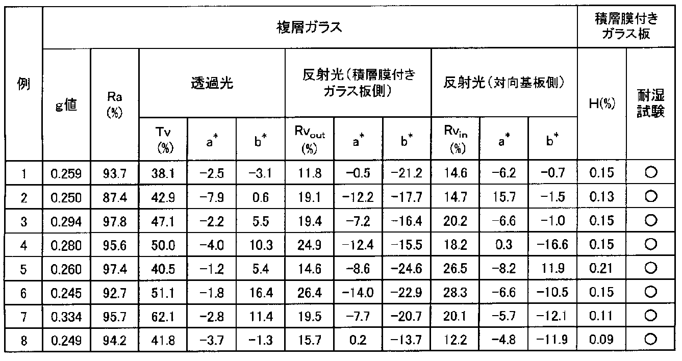
Claims (14)
- 強化された主面が矩形状のガラス板と、前記ガラス板の一方の主面上に設けられ、前記ガラス板の2以上の端面には設けられていない積層膜とを有する積層膜付きガラス板であって、前記積層膜は、該積層膜を用いた下記複層ガラスにおいて下記特性を有する積層膜付きガラス板。
板厚が5mmの第1の透明ガラス板の一方の主面上に前記積層膜を形成して試験用積層膜付きガラス板とし、該試験用積層膜付きガラス板と、板厚が6mmの第2の透明ガラス板とを、その周縁に配設したスペーサを介して前記試験用積層膜付きガラス板の積層膜面が前記第2の透明ガラス板の一方の主面に対向するように隔置し、前記試験用積層膜付きガラス板と前記第2の透明ガラス板の間に厚さ12mmの空気層を有するように作製した複層ガラスにおいて、
ISO9050:2003に準拠して測定される、前記試験用積層膜付きガラス板側からの日射に対する前記第2の透明ガラス板側での日射熱取得率(g値)が0.265以下であり、
ISO9050:2003に規定される可視光を照射して得られる透過光について、CIE1976L*a*b*色度座標によるb*が1以下であり、
ISO9050:2003に準拠して測定される、前記試験用積層膜付きガラス板側の可視光反射率が20%以下である。 - 前記積層膜は、銀を主成分として含有するn層(nは2以上の整数)の金属層と、前記金属層をそれぞれ挟むように積層されるn+1層の誘電体層を有し、
前記金属層のうち前記ガラス板に最も近い第1の金属層は、パラジウム、金、クロム、コバルトおよびニッケルから選ばれる少なくとも1種の金属を、銀と前記金属との合計量に対して6質量%以上の割合で含有する、ただし、前記割合が9質量%未満の場合は前記第1の金属層と前記ガラス板に2番目に近い第2の金属層との間の前記誘電体層の厚さが100nm以下である、もしくは、
前記第1の金属層および前記第1の金属層以外の前記金属層の少なくとも1層が、それぞれ独立に、パラジウム、金、クロム、コバルトおよびニッケルから選ばれる少なくとも1種の金属を、銀と前記金属との合計量に対して1.5質量%以上の割合で含有し、前記金属を1.5質量%以上の割合で含有する金属層における前記金属の含有量の合計が4質量%以上であり、かつ前記第1の金属層と前記ガラス板に2番目に近い第2の金属層との間の前記誘電体層の厚さが95nm以下である
請求項1に記載の積層膜付きガラス板。 - 前記積層膜は、前記積層膜表面に最も近い金属層と前記ガラス板の間に窒化物層または酸窒化物層を有しない請求項1または2に記載の積層膜付きガラス板。
- 強化された主面が矩形状のガラス板と、
前記ガラス板の一方の主面上に設けられ、前記ガラス板の2以上の端面には設けられていない積層膜とを備え、
前記積層膜は、
銀を主成分として含有するn層(nは2以上の整数)の金属層と、前記金属層をそれぞれ挟むように積層されるn+1層の誘電体層を有し、
前記金属層のうち前記ガラス板に最も近い第1の金属層は、パラジウム、金、クロム、コバルトおよびニッケルから選ばれる少なくとも1種の金属を、銀と前記金属との合計量に対して6質量%以上の割合で含有する、ただし、前記割合が9質量%未満の場合は前記第1の金属層と前記ガラス板に2番目に近い第2の金属層との間の前記誘電体層の厚さが100nm以下である、もしくは、
前記第1の金属層および前記第1の金属層以外の前記金属層の少なくとも1層が、それぞれ独立に、パラジウム、金、クロム、コバルトおよびニッケルから選ばれる少なくとも1種の金属を、銀と前記金属との合計量に対して1.5質量%以上の割合で含有し、かつ前記金属を1.5質量%以上の割合で含有する金属層における前記金属の含有量の合計が4質量%以上であり、かつ前記第1の金属層と前記ガラス板に2番目に近い第2の金属層との間の前記誘電体層の厚さが95nm以下である
積層膜付きガラス板。 - 前記積層膜は、前記積層膜表面に最も近い前記金属層と、前記ガラス板との間に窒化物層または酸窒化物層を有しない請求項4に記載の積層膜付きガラス板。
- 前記積層膜付きガラス板は、ヘイズ値が2%以下である請求項1~5のいずれか1項に記載の積層膜付きガラス板。
- 前記積層膜付きガラス板を、50℃、90%RHの条件下に2週間保管した後、前記積層膜表面の100mm×100mmの範囲で観察される直径0.5mm以上の白点が5個以内である請求項1~6のいずれか1項に記載の積層膜付きガラス板。
- 前記金属層の層数は2であり、前記第1の金属層の厚さに対する、もう一方の金属層の厚さの比が、0.8~1.6の範囲にある請求項2~7のいずれか1項に記載の積層膜付きガラス板。
- 強化された主面が矩形状の第1のガラス板と、前記第1のガラス板の一方の主面上に設けられ、前記第1のガラス板の2以上の端面には設けられていない積層膜とを有する積層膜付きガラス板と、
前記積層膜付きガラス板とスペーサを介して離間して配置された主面が矩形状の第2のガラス板と、
を備える複層ガラスであり、
ISO9050:2003に準拠して測定される、前記積層膜付きガラス板側からの日射に対する前記第2のガラス板側での日射熱取得率(g値)が0.265以下であり、
ISO9050:2003に規定される可視光を照射して得られる透過光について、CIE1976L*a*b*色度座標によるb*が1以下であり、
ISO9050:2003に準拠して測定される、前記積層膜付きガラス板側の可視光反射率が20%以下である複層ガラス。 - ISO9050:2003に準拠して測定される、前記第2のガラス板側の可視光反射率が20%以下である請求項9に記載の複層ガラス。
- JIS Z8726(1990)に準拠してD65光源を使用し平均演色性評価数(Ra)により評価される透過光の演色性が85%以上である請求項9または10に記載の複層ガラス。
- 前記積層膜付きガラス板側および前記第2のガラス板側に、ISO9050:2003に規定される可視光を照射して得られる各反射光の、CIE1976L*a*b*色度座標によるa*およびb*がいずれも2以下である請求項9~11のいずれか1項に記載の複層ガラス。
- ISO9050:2003に準拠して測定される可視光透過率が30%以上である、請求項9~12のいずれか1項に記載の複層ガラス。
- ISO9050:2003に準拠して測定される前記積層膜付きガラス板側の可視光反射率と、前記第2のガラス板側の可視光反射率の差が、10%以下である、請求項9~13のいずれか1項に記載の複層ガラス。
Priority Applications (4)
| Application Number | Priority Date | Filing Date | Title |
|---|---|---|---|
| AU2016213183A AU2016213183B2 (en) | 2015-01-28 | 2016-01-26 | Coated glass sheet and insulated glazing |
| JP2016572054A JP6601419B2 (ja) | 2015-01-28 | 2016-01-26 | 積層膜付きガラス板および複層ガラス |
| CN201680007895.9A CN107207331A (zh) | 2015-01-28 | 2016-01-26 | 带层叠膜的玻璃板及多层玻璃 |
| MYPI2017702729A MY186067A (en) | 2015-01-28 | 2016-01-26 | Glass plate with stacked film and double glazing glass |
Applications Claiming Priority (2)
| Application Number | Priority Date | Filing Date | Title |
|---|---|---|---|
| JP2015014397 | 2015-01-28 | ||
| JP2015-014397 | 2015-01-28 |
Publications (1)
| Publication Number | Publication Date |
|---|---|
| WO2016121752A1 true WO2016121752A1 (ja) | 2016-08-04 |
Family
ID=56543363
Family Applications (1)
| Application Number | Title | Priority Date | Filing Date |
|---|---|---|---|
| PCT/JP2016/052167 Ceased WO2016121752A1 (ja) | 2015-01-28 | 2016-01-26 | 積層膜付きガラス板および複層ガラス |
Country Status (5)
| Country | Link |
|---|---|
| JP (1) | JP6601419B2 (ja) |
| CN (1) | CN107207331A (ja) |
| AU (1) | AU2016213183B2 (ja) |
| MY (1) | MY186067A (ja) |
| WO (1) | WO2016121752A1 (ja) |
Cited By (4)
| Publication number | Priority date | Publication date | Assignee | Title |
|---|---|---|---|---|
| JP2018145069A (ja) * | 2017-03-08 | 2018-09-20 | 積水化学工業株式会社 | 合わせガラス用中間膜、合わせガラス、及び、合わせガラスシステム |
| WO2018207555A1 (ja) * | 2017-05-12 | 2018-11-15 | セントラル硝子株式会社 | 日射遮蔽部材 |
| JPWO2019176862A1 (ja) * | 2018-03-11 | 2021-03-25 | 日本板硝子株式会社 | 複層ガラスパネル |
| US11673828B2 (en) * | 2018-11-16 | 2023-06-13 | Saint-Gobain Glass France | Heat-treated material with improved mechanical properties |
Citations (6)
| Publication number | Priority date | Publication date | Assignee | Title |
|---|---|---|---|---|
| JP2006117482A (ja) * | 2004-10-22 | 2006-05-11 | Nippon Sheet Glass Co Ltd | 熱線遮蔽ガラス及び熱線遮蔽複層ガラス |
| JP2008540311A (ja) * | 2005-05-11 | 2008-11-20 | エージーシー フラット グラス ユーロップ エスエー | 太陽遮蔽積層構造 |
| JP2012136405A (ja) * | 2010-12-27 | 2012-07-19 | Asahi Glass Co Ltd | 積層体、複層ガラス、および積層体の製造方法 |
| WO2013129624A1 (ja) * | 2012-02-28 | 2013-09-06 | 旭硝子株式会社 | 積層体の製造方法、および積層体 |
| JP2014508093A (ja) * | 2011-03-03 | 2014-04-03 | ガーディアン・インダストリーズ・コーポレーション | Ni及び/又はTiを含むバリア層、バリア層を包含する被覆物品並びにそれらの製造方法 |
| JP2014076918A (ja) * | 2012-10-11 | 2014-05-01 | Central Glass Co Ltd | 窓用ガラス積層体 |
Family Cites Families (6)
| Publication number | Priority date | Publication date | Assignee | Title |
|---|---|---|---|---|
| CN2080065U (zh) * | 1990-11-01 | 1991-07-03 | 伟光镀膜玻璃有限公司 | 四层膜结构的镀膜玻璃 |
| EP1280179A3 (en) * | 2001-07-23 | 2003-09-03 | Asahi Glass Company Ltd. | Flat display panel |
| EP2426552A1 (en) * | 2006-03-03 | 2012-03-07 | Gentex Corporation | Electro-optic elements incorporating improved thin-film coatings |
| CN202448402U (zh) * | 2012-01-13 | 2012-09-26 | 林嘉宏 | 具有多层功能层的低辐射镀膜玻璃 |
| KR101809336B1 (ko) * | 2012-12-28 | 2017-12-14 | 니혼 이타가라스 가부시키가이샤 | 감압 복층 유리 패널 |
| CN203391418U (zh) * | 2013-07-25 | 2014-01-15 | 林嘉佑 | 高透型可钢化双银低辐射镀膜玻璃 |
-
2016
- 2016-01-26 MY MYPI2017702729A patent/MY186067A/en unknown
- 2016-01-26 AU AU2016213183A patent/AU2016213183B2/en not_active Ceased
- 2016-01-26 WO PCT/JP2016/052167 patent/WO2016121752A1/ja not_active Ceased
- 2016-01-26 JP JP2016572054A patent/JP6601419B2/ja not_active Expired - Fee Related
- 2016-01-26 CN CN201680007895.9A patent/CN107207331A/zh active Pending
Patent Citations (6)
| Publication number | Priority date | Publication date | Assignee | Title |
|---|---|---|---|---|
| JP2006117482A (ja) * | 2004-10-22 | 2006-05-11 | Nippon Sheet Glass Co Ltd | 熱線遮蔽ガラス及び熱線遮蔽複層ガラス |
| JP2008540311A (ja) * | 2005-05-11 | 2008-11-20 | エージーシー フラット グラス ユーロップ エスエー | 太陽遮蔽積層構造 |
| JP2012136405A (ja) * | 2010-12-27 | 2012-07-19 | Asahi Glass Co Ltd | 積層体、複層ガラス、および積層体の製造方法 |
| JP2014508093A (ja) * | 2011-03-03 | 2014-04-03 | ガーディアン・インダストリーズ・コーポレーション | Ni及び/又はTiを含むバリア層、バリア層を包含する被覆物品並びにそれらの製造方法 |
| WO2013129624A1 (ja) * | 2012-02-28 | 2013-09-06 | 旭硝子株式会社 | 積層体の製造方法、および積層体 |
| JP2014076918A (ja) * | 2012-10-11 | 2014-05-01 | Central Glass Co Ltd | 窓用ガラス積層体 |
Cited By (8)
| Publication number | Priority date | Publication date | Assignee | Title |
|---|---|---|---|---|
| JP2018145069A (ja) * | 2017-03-08 | 2018-09-20 | 積水化学工業株式会社 | 合わせガラス用中間膜、合わせガラス、及び、合わせガラスシステム |
| WO2018207555A1 (ja) * | 2017-05-12 | 2018-11-15 | セントラル硝子株式会社 | 日射遮蔽部材 |
| CN110650841A (zh) * | 2017-05-12 | 2020-01-03 | 中央硝子株式会社 | 日照遮蔽构件 |
| JPWO2018207555A1 (ja) * | 2017-05-12 | 2020-03-12 | セントラル硝子株式会社 | 日射遮蔽部材 |
| JP7025665B2 (ja) | 2017-05-12 | 2022-02-25 | セントラル硝子株式会社 | 日射遮蔽部材 |
| JPWO2019176862A1 (ja) * | 2018-03-11 | 2021-03-25 | 日本板硝子株式会社 | 複層ガラスパネル |
| JP7266020B2 (ja) | 2018-03-11 | 2023-04-27 | 日本板硝子株式会社 | 複層ガラスパネル |
| US11673828B2 (en) * | 2018-11-16 | 2023-06-13 | Saint-Gobain Glass France | Heat-treated material with improved mechanical properties |
Also Published As
| Publication number | Publication date |
|---|---|
| AU2016213183A1 (en) | 2017-07-06 |
| CN107207331A (zh) | 2017-09-26 |
| JPWO2016121752A1 (ja) | 2017-11-09 |
| AU2016213183B2 (en) | 2019-07-25 |
| MY186067A (en) | 2021-06-18 |
| JP6601419B2 (ja) | 2019-11-06 |
Similar Documents
| Publication | Publication Date | Title |
|---|---|---|
| JP5846203B2 (ja) | 低放射率積層体、および複層ガラス | |
| KR101941718B1 (ko) | 박막 다중층이 구비된 투명 기판 | |
| US9919960B2 (en) | Antisolar glazing | |
| JP6090322B2 (ja) | 積層体 | |
| JP2014514997A (ja) | 2つの低放射率積層体を備えた断熱多重グレージング | |
| WO2014109368A1 (ja) | 光学多層膜、積層体、および複層ガラス | |
| JP6767661B2 (ja) | グレー色調低放射ガラス | |
| JPWO2018051638A1 (ja) | 日射遮蔽部材 | |
| JP6601419B2 (ja) | 積層膜付きガラス板および複層ガラス | |
| US20220034155A1 (en) | Coated glass pane | |
| JP6024369B2 (ja) | 窓用ガラス積層体 | |
| JP2017132666A (ja) | グレー色調低放射ガラス、及びグレー色調低放射ガラスの製造方法 | |
| JP5463686B2 (ja) | 窓用ガラス積層体 | |
| JP6703267B2 (ja) | グレー色調低放射ガラス | |
| WO2014109369A1 (ja) | 積層体および複層ガラス | |
| JP2019518708A (ja) | 太陽光線制御グレイジング | |
| JP2019182684A (ja) | 低放射ガラス | |
| JP2008222507A (ja) | 複層ガラス | |
| JP6459374B2 (ja) | 窓ガラスおよび積層膜付き透明基板 | |
| KR20160079513A (ko) | 차폐성능이 향상된 열처리 가능한 저방사 유리 및 그 제조방법 | |
| JP6287502B2 (ja) | 低放射窓材 | |
| WO2016189992A1 (ja) | 合わせガラス |
Legal Events
| Date | Code | Title | Description |
|---|---|---|---|
| 121 | Ep: the epo has been informed by wipo that ep was designated in this application |
Ref document number: 16743355 Country of ref document: EP Kind code of ref document: A1 |
|
| ENP | Entry into the national phase |
Ref document number: 2016572054 Country of ref document: JP Kind code of ref document: A |
|
| ENP | Entry into the national phase |
Ref document number: 2016213183 Country of ref document: AU Date of ref document: 20160126 Kind code of ref document: A |
|
| NENP | Non-entry into the national phase |
Ref country code: DE |
|
| 122 | Ep: pct application non-entry in european phase |
Ref document number: 16743355 Country of ref document: EP Kind code of ref document: A1 |