WO2016121259A1 - タービン - Google Patents
タービン Download PDFInfo
- Publication number
- WO2016121259A1 WO2016121259A1 PCT/JP2015/085210 JP2015085210W WO2016121259A1 WO 2016121259 A1 WO2016121259 A1 WO 2016121259A1 JP 2015085210 W JP2015085210 W JP 2015085210W WO 2016121259 A1 WO2016121259 A1 WO 2016121259A1
- Authority
- WO
- WIPO (PCT)
- Prior art keywords
- rotor
- radial direction
- grooves
- blade
- shroud
- Prior art date
- Legal status (The legal status is an assumption and is not a legal conclusion. Google has not performed a legal analysis and makes no representation as to the accuracy of the status listed.)
- Ceased
Links
Images



Classifications
-
- F—MECHANICAL ENGINEERING; LIGHTING; HEATING; WEAPONS; BLASTING
- F01—MACHINES OR ENGINES IN GENERAL; ENGINE PLANTS IN GENERAL; STEAM ENGINES
- F01D—NON-POSITIVE DISPLACEMENT MACHINES OR ENGINES, e.g. STEAM TURBINES
- F01D11/00—Preventing or minimising internal leakage of working-fluid, e.g. between stages
- F01D11/02—Preventing or minimising internal leakage of working-fluid, e.g. between stages by non-contact sealings, e.g. of labyrinth type
-
- F—MECHANICAL ENGINEERING; LIGHTING; HEATING; WEAPONS; BLASTING
- F01—MACHINES OR ENGINES IN GENERAL; ENGINE PLANTS IN GENERAL; STEAM ENGINES
- F01D—NON-POSITIVE DISPLACEMENT MACHINES OR ENGINES, e.g. STEAM TURBINES
- F01D5/00—Blades; Blade-carrying members; Heating, heat-insulating, cooling or antivibration means on the blades or the members
- F01D5/02—Blade-carrying members, e.g. rotors
-
- F—MECHANICAL ENGINEERING; LIGHTING; HEATING; WEAPONS; BLASTING
- F01—MACHINES OR ENGINES IN GENERAL; ENGINE PLANTS IN GENERAL; STEAM ENGINES
- F01D—NON-POSITIVE DISPLACEMENT MACHINES OR ENGINES, e.g. STEAM TURBINES
- F01D9/00—Stators
- F01D9/02—Nozzles; Nozzle boxes; Stator blades; Guide conduits, e.g. individual nozzles
- F01D9/04—Nozzles; Nozzle boxes; Stator blades; Guide conduits, e.g. individual nozzles forming ring or sector
- F01D9/041—Nozzles; Nozzle boxes; Stator blades; Guide conduits, e.g. individual nozzles forming ring or sector using blades
-
- F—MECHANICAL ENGINEERING; LIGHTING; HEATING; WEAPONS; BLASTING
- F02—COMBUSTION ENGINES; HOT-GAS OR COMBUSTION-PRODUCT ENGINE PLANTS
- F02C—GAS-TURBINE PLANTS; AIR INTAKES FOR JET-PROPULSION PLANTS; CONTROLLING FUEL SUPPLY IN AIR-BREATHING JET-PROPULSION PLANTS
- F02C7/00—Features, components parts, details or accessories, not provided for in, or of interest apart form groups F02C1/00 - F02C6/00; Air intakes for jet-propulsion plants
- F02C7/28—Arrangement of seals
-
- F—MECHANICAL ENGINEERING; LIGHTING; HEATING; WEAPONS; BLASTING
- F16—ENGINEERING ELEMENTS AND UNITS; GENERAL MEASURES FOR PRODUCING AND MAINTAINING EFFECTIVE FUNCTIONING OF MACHINES OR INSTALLATIONS; THERMAL INSULATION IN GENERAL
- F16J—PISTONS; CYLINDERS; SEALINGS
- F16J15/00—Sealings
- F16J15/16—Sealings between relatively-moving surfaces
- F16J15/18—Sealings between relatively-moving surfaces with stuffing-boxes for elastic or plastic packings
- F16J15/20—Packing materials therefor
- F16J15/22—Packing materials therefor shaped as strands, ropes, threads, ribbons, or the like
-
- F—MECHANICAL ENGINEERING; LIGHTING; HEATING; WEAPONS; BLASTING
- F16—ENGINEERING ELEMENTS AND UNITS; GENERAL MEASURES FOR PRODUCING AND MAINTAINING EFFECTIVE FUNCTIONING OF MACHINES OR INSTALLATIONS; THERMAL INSULATION IN GENERAL
- F16J—PISTONS; CYLINDERS; SEALINGS
- F16J15/00—Sealings
- F16J15/44—Free-space packings
- F16J15/447—Labyrinth packings
- F16J15/4472—Labyrinth packings with axial path
-
- F—MECHANICAL ENGINEERING; LIGHTING; HEATING; WEAPONS; BLASTING
- F01—MACHINES OR ENGINES IN GENERAL; ENGINE PLANTS IN GENERAL; STEAM ENGINES
- F01D—NON-POSITIVE DISPLACEMENT MACHINES OR ENGINES, e.g. STEAM TURBINES
- F01D5/00—Blades; Blade-carrying members; Heating, heat-insulating, cooling or antivibration means on the blades or the members
- F01D5/12—Blades
- F01D5/22—Blade-to-blade connections, e.g. for damping vibrations
- F01D5/225—Blade-to-blade connections, e.g. for damping vibrations by shrouding
-
- F—MECHANICAL ENGINEERING; LIGHTING; HEATING; WEAPONS; BLASTING
- F05—INDEXING SCHEMES RELATING TO ENGINES OR PUMPS IN VARIOUS SUBCLASSES OF CLASSES F01-F04
- F05D—INDEXING SCHEME FOR ASPECTS RELATING TO NON-POSITIVE-DISPLACEMENT MACHINES OR ENGINES, GAS-TURBINES OR JET-PROPULSION PLANTS
- F05D2220/00—Application
- F05D2220/30—Application in turbines
- F05D2220/31—Application in turbines in steam turbines
-
- F—MECHANICAL ENGINEERING; LIGHTING; HEATING; WEAPONS; BLASTING
- F05—INDEXING SCHEMES RELATING TO ENGINES OR PUMPS IN VARIOUS SUBCLASSES OF CLASSES F01-F04
- F05D—INDEXING SCHEME FOR ASPECTS RELATING TO NON-POSITIVE-DISPLACEMENT MACHINES OR ENGINES, GAS-TURBINES OR JET-PROPULSION PLANTS
- F05D2220/00—Application
- F05D2220/30—Application in turbines
- F05D2220/32—Application in turbines in gas turbines
-
- F—MECHANICAL ENGINEERING; LIGHTING; HEATING; WEAPONS; BLASTING
- F05—INDEXING SCHEMES RELATING TO ENGINES OR PUMPS IN VARIOUS SUBCLASSES OF CLASSES F01-F04
- F05D—INDEXING SCHEME FOR ASPECTS RELATING TO NON-POSITIVE-DISPLACEMENT MACHINES OR ENGINES, GAS-TURBINES OR JET-PROPULSION PLANTS
- F05D2240/00—Components
- F05D2240/10—Stators
- F05D2240/12—Fluid guiding means, e.g. vanes
- F05D2240/127—Vortex generators, turbulators, or the like, for mixing
-
- F—MECHANICAL ENGINEERING; LIGHTING; HEATING; WEAPONS; BLASTING
- F05—INDEXING SCHEMES RELATING TO ENGINES OR PUMPS IN VARIOUS SUBCLASSES OF CLASSES F01-F04
- F05D—INDEXING SCHEME FOR ASPECTS RELATING TO NON-POSITIVE-DISPLACEMENT MACHINES OR ENGINES, GAS-TURBINES OR JET-PROPULSION PLANTS
- F05D2240/00—Components
- F05D2240/55—Seals
-
- F—MECHANICAL ENGINEERING; LIGHTING; HEATING; WEAPONS; BLASTING
- F05—INDEXING SCHEMES RELATING TO ENGINES OR PUMPS IN VARIOUS SUBCLASSES OF CLASSES F01-F04
- F05D—INDEXING SCHEME FOR ASPECTS RELATING TO NON-POSITIVE-DISPLACEMENT MACHINES OR ENGINES, GAS-TURBINES OR JET-PROPULSION PLANTS
- F05D2250/00—Geometry
- F05D2250/30—Arrangement of components
- F05D2250/31—Arrangement of components according to the direction of their main axis or their axis of rotation
- F05D2250/314—Arrangement of components according to the direction of their main axis or their axis of rotation the axes being inclined in relation to each other
-
- F—MECHANICAL ENGINEERING; LIGHTING; HEATING; WEAPONS; BLASTING
- F05—INDEXING SCHEMES RELATING TO ENGINES OR PUMPS IN VARIOUS SUBCLASSES OF CLASSES F01-F04
- F05D—INDEXING SCHEME FOR ASPECTS RELATING TO NON-POSITIVE-DISPLACEMENT MACHINES OR ENGINES, GAS-TURBINES OR JET-PROPULSION PLANTS
- F05D2250/00—Geometry
- F05D2250/70—Shape
- F05D2250/71—Shape curved
-
- F—MECHANICAL ENGINEERING; LIGHTING; HEATING; WEAPONS; BLASTING
- F16—ENGINEERING ELEMENTS AND UNITS; GENERAL MEASURES FOR PRODUCING AND MAINTAINING EFFECTIVE FUNCTIONING OF MACHINES OR INSTALLATIONS; THERMAL INSULATION IN GENERAL
- F16J—PISTONS; CYLINDERS; SEALINGS
- F16J15/00—Sealings
- F16J15/44—Free-space packings
- F16J15/447—Labyrinth packings
Definitions
- This disclosure relates to turbines.
- Steam turbines and gas turbines usually have a fluid flow in a gap between a stationary part and a rotating part, for example, a gap between a moving blade and a member surrounding the moving blade or a gap between a stationary blade and a rotor.
- a sealing device capable of restricting the flow is provided.
- a steam turbine sealing device disclosed in Japanese Patent No. 5518022 has a step portion provided at a tip portion of a blade and a seal fin provided in a structure.
- the step portion has at least one step surface facing the upstream side and protrudes toward the structure body, and the seal fin extends toward the step portion and forms a minute gap with the step portion.
- a separation vortex and a main vortex are formed on the upstream side of the seal fin, and steam leakage flowing through a minute gap is reduced by the contraction effect of the separation vortex.
- An object of at least one embodiment of the present invention is to provide a turbine provided with an improved sealing device capable of reducing leakage flow as compared with the prior art.
- the inventors of the present invention have made extensive studies to achieve the above-described object.
- the flow field of the cavity between the seal fins is uniform in the circumferential direction of the rotor, the main vortex and separation vortex in the cavity are
- the vortex structure is optimal.
- the optimization of the vortex structure maximizes the strength of the separation vortex in the meridian plane and improves the sealing performance.
- the inventors of the present invention actually expected that the velocity fluctuation (secondary flow) in the circumferential direction occurred in the cavity and the kinetic energy of the fluid in the meridional plane decreased, and the main vortex and separation vortex were expected.
- the knowledge that it may become weak is also obtained.
- a turbine includes: A casing, A rotor extending inside the casing; A plurality of moving blades fixed to the rotor and arranged in a circumferential direction of the rotor; A plurality of stationary blades fixed to the casing and arranged in the circumferential direction of the rotor, the blades being connected to the blade body and the blade body, and having a clearance from the outer circumferential surface of the rotor in the radial direction of the rotor A plurality of stationary blades each having an opposing shroud, A seal device capable of restricting the flow of fluid in the gap,
- the sealing device includes: It is provided in a region of the outer peripheral surface of the rotor facing the shroud of the stationary blade in the radial direction of the rotor and faces upstream in the fluid flow direction, and the region of the outer peripheral surface is in the axial direction of the rotor At least one step surface partitioned into at least two sections; At least two seal fins respectively projecting from the
- the swirl component is imparted to the fluid flow by the swirl component imparting unit, so that the vortex structure is stabilized on the downstream side of the seal fin, and the circumferential secondary flow is unstable.
- the main vortex and the separation vortex become strong in the meridian plane. As a result, it is possible to efficiently generate a downflow due to the separation vortex, thereby reducing the flow rate of the fluid passing through the seal gap and improving the sealing performance.
- the swirl component imparting portion is formed by a plurality of grooves formed on one end side of the shroud and arranged in the circumferential direction of the rotor, Each of the plurality of grooves has an outer end portion located outside in the radial direction of the rotor, and an inner end portion located inside in the radial direction of the rotor, At least the inner end portions of the plurality of grooves extend while being inclined with respect to the radial direction of the rotor.
- the inner end portions of the plurality of grooves formed in the shroud extend while being inclined with respect to the radial direction, so that the swirl component is generated in the fluid flowing through the inner end portion with a simple configuration. Is granted.
- the inner end portion is positioned forward of the outer end portion in the rotation direction of the rotor.
- the inclination angle of the inner end portion with respect to the radial direction of the rotor is larger than the inclination angle of the outer end portion with respect to the radial direction of the rotor.
- Each of the plurality of grooves extends straightly with an inclination with respect to the radial direction. In the configuration (5), since the groove extends straight, the groove can be easily formed.
- Each of the plurality of grooves curves and extends so as to gradually deviate from the radial direction of the rotor as it approaches the inner side from the outer side in the radial direction of the rotor.
- Each of the plurality of grooves has a certain width. In the configuration (7), since the groove width is constant, the groove can be formed easily.
- each of the plurality of grooves has a portion having a different width.
- loss in the groove can be reduced while applying a swirling component to the fluid flowing in the groove.
- the plurality of grooves are formed by a plurality of blade portions formed on one end side of the shroud and arranged in the circumferential direction of the rotor.
- the plurality of grooves are formed by the wing portion, loss in the grooves can be reduced while imparting a swirling component to the fluid flowing through the grooves.
- the blade portion has a front edge portion located outside in the radial direction of the rotor, and a rear edge portion located inside in the radial direction of the rotor, The rear edge is positioned forward of the front edge in the rotational direction of the rotor.
- the trailing edge of the blade is positioned forward in the rotational direction of the rotor with respect to the leading edge, so that the fluid flowing between the blades has the same direction as the rotational direction of the rotor.
- the swirl component can be imparted. In this case, since the direction of the swirl component is the same as the rotation direction of the rotor, it is possible to reduce friction loss between the rotor and the fluid.
- the blade portion has a front edge portion located outside in the radial direction of the rotor, and a rear edge portion located inside in the radial direction of the rotor,
- the inclination angle of the rear edge portion with respect to the radial direction of the rotor is larger than the inclination angle of the front edge portion with respect to the radial direction of the rotor.
- Each of the plurality of grooves has a portion having a different depth.
- size of the turning component provided to a fluid can be adjusted because a groove
- An end face on one end side of the shroud is inclined with respect to the radial direction of the rotor.
- a larger swirling component can be imparted to the fluid because the end surface of the one end surface of the shroud is inclined.
- a turbine including a sealing device capable of reducing a leakage flow of a fluid between a stationary blade and a rotor is provided.
- FIG. 2 is a meridional cross-sectional view schematically showing an enlarged part of FIG. 1.
- FIG. 3 is a meridional sectional view schematically showing an enlarged region III in FIG. 2.
- FIG. 4 is a view corresponding to FIG. 3 of a turbine according to some embodiments.
- FIG. 4 is a view corresponding to FIG. 3 of a turbine according to some embodiments.
- FIG. 4 is a view schematically showing a schematic cross section of the shroud along the line VI-VI in FIG. 3 together with a transverse cross section of the wing body.
- FIG. 7 is a view corresponding to FIG. 6 of a turbine according to some embodiments.
- FIG. 7 is a view corresponding to FIG. 6 of a turbine according to some embodiments.
- an expression indicating that things such as “identical”, “equal”, and “homogeneous” are in an equal state not only represents an exactly equal state, but also has a tolerance or a difference that can provide the same function. It also represents the existing state.
- expressions representing shapes such as quadrangular shapes and cylindrical shapes represent not only geometrically strict shapes such as quadrangular shapes and cylindrical shapes, but also irregularities and chamfers as long as the same effects can be obtained. A shape including a part or the like is also expressed.
- the expressions “comprising”, “comprising”, “comprising”, “including”, or “having” one constituent element are not exclusive expressions for excluding the existence of the other constituent elements.
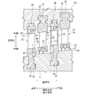
- FIG. 1 is a cross-sectional view showing a schematic configuration of a turbine 1 according to an embodiment of the present invention.
- the turbine 1 is an intermediate pressure steam turbine, and includes a casing (cabinet) 3 and a rotor 5.
- the casing 3 surrounds an intermediate portion of the rotor 5, and both end portions of the rotor 5 are rotatably supported by radial bearings 7.
- the turbine 1 is an axial flow turbine, and a plurality of moving blade rows 9 are fixed to the rotor 5 so as to be separated from each other in the axial direction of the rotor 5 (hereinafter also simply referred to as the axial direction).
- a plurality of stationary blade rows 16 that are spaced apart from each other in the axial direction are fixed to the casing 3 via blade rings 13 and 14.
- a cylindrical internal flow path 18 is formed between the blade rings 13 and 14 and the rotor 5, and the stationary blade row 16 and the moving blade row 9 are disposed in the internal flow path 18.
- Each stationary blade row 16 includes a plurality of stationary blades 20 arranged in the circumferential direction of the rotor 5 (hereinafter also simply referred to as the circumferential direction), and each stationary blade 20 is fixed to the blade rings 13 and 14. Yes.
- Each blade array 9 includes a plurality of blades (turbine blades) 22 arranged in the circumferential direction, and each blade 22 is fixed to the rotor 5.
- the rotor 5 is connected to, for example, a generator 23, and the generator 23 is driven by the rotor 5.
- the casing 3 has a steam inlet 3a in the center in the axial direction and two steam outlets 3b on both sides of the steam inlet 3a.
- the turbine 1 is a double-flow exhaust type turbine. For this reason, two internal flow paths 18 are formed in the casing 3 in the axial direction from the center toward the opposite sides.
- FIG. 2 is a meridional sectional view schematically showing an enlarged part of FIG. Specifically, FIG. 2 shows two stator blades 20, 20 belonging to different stator blade rows 16 and two rotor blades 22, 22 arranged next to the stator blades 20, 20, the rotor 5 and the blade ring. 13 is schematically shown.
- the rotor 5 is formed with a blade groove 24 extending along the circumferential direction.
- the moving blade 22 has a blade root portion 26, a blade body (blade profile portion) 27, and a shroud (tip shroud portion) 28 that are integrally formed with each other.
- the blade 22 is fixed to the rotor 5 by fitting the blade root portion 26 into the blade groove 24.
- a seal member 30 is attached to a portion of the blade ring 13 that faces the shroud 28 of the rotor blade 22, and the seal member 30 can limit the leakage flow in the gap between the shroud 28 and the blade ring 13.
- the rotor 5 and the rotor blade 22 are collectively referred to as a rotor assembly.
- the blade ring 13 has a blade groove 32 extending in the circumferential direction.
- the stationary blade 20 includes a blade root portion 33, a blade body (blade profile portion) 34, and a shroud (hub shroud portion) 35 that are integrally formed with each other.
- the stationary blade 20 is fixed to the blade ring 13 and fixed to the casing 3 through the blade ring 13.
- a seal member 37 is attached to the shroud 35 of the stationary blade 20 on the rotor 5 side, and the seal member 37 is a part of the seal device 40 that can restrict the leakage flow in the gap between the shroud 35 and the rotor 5. Is configured.
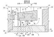
- FIG. 3 is a meridional sectional view schematically showing an enlarged region III in FIG. 4 and 5 are views corresponding to FIG. 3 of the turbine 1 according to some embodiments.
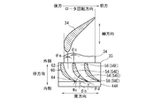
- FIG. 6 is a view schematically showing a cross section of the shroud 35 along the line VI-VI in FIG. 7 and 8 are views corresponding to FIG. 6 of the turbine 1 according to some embodiments.
- the seal device 40 includes at least one step surface 42, at least two seal fins 44 ⁇ / b> A and 44 ⁇ / b> B, and a swivel component applying unit 46.
- the step surface 42 is provided in the region of the outer peripheral surface of the rotor 5 that faces the shroud 35 of the stationary blade 20 in the radial direction, and upstream in the fluid flow direction in the gap 48 between the shroud 35 and the outer peripheral surface of the rotor 5. It is suitable.
- the step surface 42 divides the region of the outer peripheral surface of the rotor 5 facing the shroud 35 into at least two sections 50 ⁇ / b> A and 50 ⁇ / b> B in the axial direction of the rotor 5.
- the section 50B includes a step portion 51 that has a step surface 42 and protrudes from the section 50A in the radial direction.
- the at least two seal fins 44A and 44B are provided on the seal member 37 and have a fin shape.
- the seal member 37 has a base portion 38 that is fixed flush with the shroud 35, and at least two seal fins 44 ⁇ / b> A and 44 ⁇ / b> B protrude from the base portion 38.
- the at least two seal fins 44A and 44B protrude from the stationary blade 20 toward the at least two sections 50A and 50B, respectively, and seal gaps between the at least two sections 50A and 50B. 52A and 52B exist to face each other.
- the seal gap 52B is separated from the step surface 42 in the axial direction, and the cavity 53 between the seal fins 44A and 44B extends in the axial direction across the step surface 42.
- the swirl component applying unit 46 is provided on one end side of the shroud 35 of the stationary blade 20 in the axial direction of the rotor 5 and can apply a swirl component to the fluid flowing toward the seal gap 52A.
- the main vortex MV is formed on the upstream side in the cavity 53, while on the downstream side.
- a separation vortex CV is formed.
- the swirl component is imparted to the fluid flow by the swirl component imparting section 46, so that a vortex structure is formed in the cavity 53 downstream of the seal fin 44A, that is, between the seal fin 44A and the seal fin 44B. Stable and unstable secondary flow in the circumferential direction is suppressed, and the main vortex MV and separation vortex CV become stronger in the meridian plane. As a result, it is possible to efficiently generate a downflow due to the separation vortex CV, thereby reducing the flow rate of the fluid passing through the seal gap 52B and improving the sealing performance.
- the swivel component applying part 46 is formed by a plurality of grooves 54 formed on one end side of the shroud 35 and arranged in the circumferential direction of the rotor 5. ing.
- Each of the plurality of grooves 54 includes an outer end portion 56 positioned on the outer side in the radial direction and an inner end portion 58 positioned on the inner side in the radial direction, and at least the inner end portions 58 of the plurality of grooves 54 are , Extending obliquely with respect to the radial direction.
- the inner end 58 is outside in the rotational direction of the rotor 5 (hereinafter also simply referred to as the rotational direction). It is located in front of the end portion 56.
- the inclination angle ⁇ b of the inner end portions 58D and 58E with respect to the radial direction of the rotor 5 is set to be outside the radial direction. It is larger than the inclination angle ⁇ a of the end portions 56D and 56E.
- the inclination angle ⁇ a of the outer end portions 56D and 56E with respect to the radial direction of the rotor 5 is smaller than the inclination angle ⁇ b of the inner end portions 58D and 58E, fluid flows into the outer end portions 56D and 56E of the grooves 54D and 54E.
- each of the plurality of grooves 54 ⁇ / b> A extends straightly while being inclined with respect to the radial direction. In the above configuration, since the groove 54A extends straight, the groove 54A can be easily formed.
- each of the plurality of grooves 54 ⁇ / b> D and 54 ⁇ / b> E gradually deviates from the radial direction as it approaches the inner side from the outer side in the radial direction of the rotor 5. Curved and extended.
- the grooves 54D and 54E are curved and extended so as to gradually deviate from the radial direction of the rotor 5 as they approach the inner side from the outer side in the radial direction of the rotor 5, so that the fluid flowing through the grooves 54D and 54E A large swirl component can be imparted to.
- each of the plurality of grooves 54A, 54D has a constant width W, as shown in FIGS. In the above configuration, since the widths W of the grooves 54A and 54D are constant, the grooves 54A and 54D can be easily formed.
- each of the plurality of grooves 54 ⁇ / b> E has portions having different widths.
- the groove 54E since the groove 54E has portions having different widths, loss in the groove 54 can be reduced while applying a swirling component to the fluid flowing through the groove 54E.
- the width of each of the plurality of grooves 54 ⁇ / b> E is gradually narrowed from the outside toward the inside in the radial direction of the rotor 5.
- the width of the plurality of grooves 54E is gradually narrowed, so that the speed of the fluid flowing through the groove 54E can be increased, and a stronger swirling component can be imparted to the fluid flowing through the groove 54E.
- the plurality of grooves 54 ⁇ / b> E are formed by a plurality of wing parts 60 formed on one end side of the shroud 35 and arranged in the circumferential direction of the rotor 5.
- the plurality of grooves 54 are formed by the wing portion 60, loss in the grooves 54 can be reduced while imparting a swirling component to the fluid flowing in the grooves 54.
- the width of each of the plurality of grooves 54 ⁇ / b> E gradually decreases from the outside toward the inside in the radial direction of the rotor 5, and is the most in the radial direction.
- the inner throat has the smallest width Ws.
- the speed of the fluid flowing through the groove 54E can be increased by gradually reducing the width of the plurality of grooves 54E and minimizing it at the throat portion. Can be granted.
- the wing portion 60 includes a front edge portion 62 located on the outer side in the radial direction of the rotor 5 and a rear portion located on the inner side in the radial direction of the rotor 5. It has an edge part 64, and the rear edge part 64 is located in front of the front edge part 62 in the rotational direction of the rotor 5.
- the trailing edge portion 64 of the wing portion 60 is positioned in front of the leading edge portion 62 in the rotation direction of the rotor 5, and therefore the rotation direction of the rotor 5 with respect to the fluid flowing between the wing portions 60.
- the turning component in the same direction can be applied. In this case, since the direction of the swirl component is the same as the rotation direction of the rotor 5, friction loss between the rotor 5 and the fluid can be reduced.
- the inclination angle ⁇ d of the rear edge portion 64 with respect to the radial direction of the rotor 5 is larger than the inclination angle ⁇ c of the front edge portion 62 with respect to the radial direction of the rotor 5. .
- the inclination angle ⁇ c of the front edge portion 62 with respect to the radial direction of the rotor 5 is smaller than the inclination angle ⁇ d of the rear edge portion 64, the fluid easily flows into the outer end portion 56E of the groove 54E, thereby reducing the inflow loss. can do.
- the width of the trailing edge 64 of the wing 60 is less than the width of the leading edge 62, as shown in FIG.
- a wake is reduced and a flow loss is reduced because the width
- a large swirl component can be imparted to the fluid, and the sealing performance is further improved.
- the end surface 66 on one end side of the shroud 35 is inclined with respect to the radial direction of the rotor 5. In the above configuration, since the end surface 66 of the one end surface of the shroud 35 is inclined, a larger swirl component can be imparted to the fluid.
- each of the plurality of grooves 54 ⁇ / b> C has portions having different depths.
- the size of the swirling component imparted to the fluid can be adjusted because the groove 54C has portions having different depths.
- one end side of the shroud 35 in which the groove 54 is formed is located upstream in the mainstream flow direction.
- the groove 54 extends through the end portion of the shroud 35 in the radial direction and opens on both sides of the shroud 35 in the radial direction.
- the groove 54 opens in the end surface 66 of the shroud 35, as shown in FIGS.
- the present invention is not limited to the above-described embodiments, and includes forms obtained by changing the above-described embodiments and forms obtained by combining these forms.
- the number of seal fins is not limited to two, and may be three or more.
- the number of step surfaces may be two or more.
- the shroud 35 is not limited to the integral shroud, and may be an inner ring constituting a part of the nozzle diaphragm.
- the turbine 1 is not limited to a reaction turbine, and may be an impulse turbine.
- the turbine 1 is not limited to an intermediate pressure steam turbine, and may be a high pressure or low pressure steam turbine.
- the turbine 1 may be a single flow type.
- the turbine 1 may be a gas turbine, and the working fluid is not limited to steam.
- the sealing device described above can be applied to all rotating machines such as a compressor and a shaft end seal in addition to the turbine.
Landscapes
- Engineering & Computer Science (AREA)
- General Engineering & Computer Science (AREA)
- Mechanical Engineering (AREA)
- Chemical & Material Sciences (AREA)
- Combustion & Propulsion (AREA)
- Turbine Rotor Nozzle Sealing (AREA)
- Sealing Using Fluids, Sealing Without Contact, And Removal Of Oil (AREA)
- Sealing Devices (AREA)
Abstract
Description
例えば、日本国特許第5518022号公報が開示する蒸気タービンのシール装置は、ブレードの先端部に設けられたステップ部と、構造体に設けられたシールフィンとを有している。ステップ部は、上流側に面する少なくとも1つの段差面を有して構造体側に突出し、シールフィンは、ステップ部に向かって延出し、ステップ部との間に微小隙間を形成する。
この蒸気タービンのシール装置では、シールフィンの上流側に剥離渦及び主渦が形成され、剥離渦の縮流効果によって、微小隙間を流れる蒸気漏洩が低減される。
一方、本発明者等は、現実には、空洞において周方向の速度変動(2次流れ)が発生して子午面内の流体の運動エネルギが低下し、主渦及び剥離渦が期待していたよりも弱くなることがあるとの知見を得た。そして、主渦や剥離渦の中心位置が周方向にうねり、渦構造が壊れてしまうことがあるとの知見を得た。更に、シールフィンがロータの径方向に対し傾斜している場合に、このような傾向が強くなるとの知見も得た。また、空洞に流入する流体の周方向速度の絶対速度が零に近い場合にも、このような傾向が強くなるとの知見も得た。
これらの知見に基づき、本発明者等は更に検討を重ね、シールフィン間の空洞の流れ場をロータの周方向に一様にすることが可能な構成を見出し、本発明を創作するに至った。
ケーシングと、
前記ケーシングの内部を延びるロータと、
前記ロータに固定され且つ前記ロータの周方向に配列された複数の動翼と、
前記ケーシングに対し固定され且つ前記ロータの周方向に配列された複数の静翼であって、翼本体、及び、前記翼本体に連なり、前記ロータの径方向にて前記ロータの外周面と隙間を存して対向するシュラウドをそれぞれ有する複数の静翼と、
前記隙間における流体の流れを制限可能なシール装置とを備え、
前記シール装置は、
前記ロータの径方向にて前記静翼のシュラウドと対向する前記ロータの外周面の領域に設けられるとともに前記流体の流れ方向にて上流を向き、前記外周面の領域を前記ロータの軸方向にて少なくとも2つの区画に区画する少なくとも1つの段差面と、
前記静翼から前記少なくとも2つの区画に向かってそれぞれ突出し、前記少なくとも2つの区画とシール隙間を存してそれぞれ対向する少なくとも2つのシールフィンと、
前記ロータの軸方向にて前記静翼のシュラウドの一端側に設けられ、前記シール隙間に向かって流れる流体に旋回成分を付与可能な旋回成分付与部と、
を有する。
前記旋回成分付与部は、前記シュラウドの一端側に形成され且つ前記ロータの周方向に配列された複数の溝によって構成され、
前記複数の溝の各々は、前記ロータの径方向にて外側に位置する外端部、及び、前記ロータの径方向にて内側に位置する内端部を有し、
前記複数の溝の少なくとも前記内端部は、前記ロータの径方向に対し傾斜して延びている。
前記複数の溝の各々において、前記内端部は、前記ロータの回転方向にて前記外端部よりも前方に位置している。
前記複数の溝の各々において、前記ロータの径方向に対する前記内端部の傾斜角度は、前記ロータの径方向に対する前記外端部の傾斜角度よりも大である。
前記複数の溝の各々は、前記径方向に対し傾斜して真っ直ぐに延びている。
上記構成(5)では、溝が真っ直ぐに伸びているので、容易に溝を形成することができる。
前記複数の溝の各々は、前記ロータの径方向にて外側から内側に近付くにつれて、前記ロータの径方向から徐々に逸れるように湾曲して延びている。
前記複数の溝の各々は一定の幅を有する。
上記構成(7)では、溝の幅が一定であるので、容易に溝を形成することができる。
前記複数の溝の各々は相互に幅が異なる部分を有する。
上記構成(8)では、幅が異なる部分を溝が有するので、溝を流れる流体に対し旋回成分を付与しながら、溝における損失を低減することができる。
前記複数の溝は、前記シュラウドの一端側に形成され且つ前記ロータの周方向に配列された複数の翼部によって形成されている。
上記構成(9)では、翼部によって複数の溝が形成されているので、溝を流れる流体に対し旋回成分を付与しながら、溝における損失を低減することができる。
前記翼部は、前記ロータの径方向にて外側に位置する前縁部、及び、前記ロータの径方向にて内側に位置する後縁部を有し、
前記後縁部は、前記ロータの回転方向にて前記前縁部よりも前方に位置している。
前記翼部は、前記ロータの径方向にて外側に位置する前縁部、及び、前記ロータの径方向にて内側に位置する後縁部を有し、
前記ロータの径方向に対する前記後縁部の傾斜角度は、前記ロータの径方向に対する前記前縁部の傾斜角度よりも大である。
前記複数の溝の各々は、相互に深さが異なる部分を有する。
上記構成(12)では、溝が、相互に深さが異なる部分を有することで、流体に付与する旋回成分の大きさを調整することができる。
前記シュラウドの一端側の端面は、前記ロータの径方向に対し傾斜している。
上記構成(13)では、シュラウドの一端面の端面が傾斜していることで、より大きな旋回成分を流体に付与することができる。
例えば、「ある方向に」、「ある方向に沿って」、「平行」、「直交」、「中心」、「同心」或いは「同軸」等の相対的或いは絶対的な配置を表す表現は、厳密にそのような配置を表すのみならず、公差、若しくは、同じ機能が得られる程度の角度や距離をもって相対的に変位している状態も表すものとする。
例えば、「同一」、「等しい」及び「均質」等の物事が等しい状態であることを表す表現は、厳密に等しい状態を表すのみならず、公差、若しくは、同じ機能が得られる程度の差が存在している状態も表すものとする。
例えば、四角形状や円筒形状等の形状を表す表現は、幾何学的に厳密な意味での四角形状や円筒形状等の形状を表すのみならず、同じ効果が得られる範囲で、凹凸部や面取り部等を含む形状も表すものとする。
一方、一の構成要素を「備える」、「具える」、「具備する」、「含む」、又は、「有する」という表現は、他の構成要素の存在を除外する排他的な表現ではない。
なお、ロータ5と動翼22をまとめてロータアセンブリとも称する。
段差面42は、径方向にて静翼20のシュラウド35と対向するロータ5の外周面の領域に設けられ、シュラウド35とロータ5の外周面との隙間48における流体の流れ方向にて上流を向いている。そして、段差面42は、シュラウド35と対向するロータ5の外周面の領域をロータ5の軸方向にて少なくとも2つの区画50A,50Bに区画している。つまり、区画50A,50Bは、段差面42を介して連なっており、流体の流れ方向にて下流の区画50Bは、上流の区画50Aよりも、径方向にて外側に位置している。区画50Bは、段差面42を有して区画50Aから径方向に突出したステップ部51によって構成されている。
旋回成分付与部46は、ロータ5の軸方向にて静翼20のシュラウド35の一端側に設けられ、シール隙間52Aに向かって流れる流体に旋回成分を付与可能である。
上記構成では、シュラウド35に形成された複数の溝54の内端部58が径方向に対し傾斜して延びているので、簡単な構成にて、内端部58を流れる流体に旋回成分が付与される。
上記構成では、ロータ5の径方向に対する外端部56D,56Eの傾斜角度θaが内端部58D,58Eの傾斜角度θbよりも小さいので、流体が溝54D,54Eの外端部56D,56Eに流入しやすく、流入損失を低減することができる。一方で、径方向に対する内端部58D,58Eの傾斜角度θaが外端部56D,56Eの傾斜角よりも大きいので、溝54を流れる流体に大きな旋回成分を付与することができる。この結果、より多くの流体に大きな旋回成分を付与することができ、シール性能がより一層向上する。
上記構成では、溝54Aが真っ直ぐに伸びているので、容易に溝54Aを形成することができる。
上記構成では、溝54D,54Eが、ロータ5の径方向にて外側から内側に近付くにつれて、ロータ5の径方向から徐々に逸れるように湾曲して延びているので、溝54D,54Eを流れる流体に大きな旋回成分を付与することができる。
上記構成では、溝54A,54Dの幅Wが一定であるので、容易に溝54A,54Dを形成することができる。
上記構成では、幅が異なる部分を溝54Eが有するので、溝54Eを流れる流体に対し旋回成分を付与しながら、溝54における損失を低減することができる。
上記構成では、複数の溝54Eの幅が徐々に狭くなることで、溝54Eを流れる流体の速度を増大させることができ、溝54Eを流れる流体に対しより強い旋回成分を付与することができる。
上記構成では、翼部60によって複数の溝54が形成されているので、溝54を流れる流体に対し旋回成分を付与しながら、溝54における損失を低減することができる。
上記構成では、複数の溝54Eの幅が徐々に狭くなりスロート部で最小になることで、溝54Eを流れる流体の速度を増大させることができ、溝54Eを流れる流体に対しより強い旋回成分を付与することができる。
上記構成では、ロータ5の径方向に対する前縁部62の傾斜角度θcが後縁部64の傾斜角度θdよりも小さいので、流体が溝54Eの外端部56Eに流入しやすく、流入損失を低減することができる。一方で、ロータ5の径方向に対する後縁部64の傾斜角度θdが前縁部62の傾斜角θcよりも大きいので、溝54Eを流れる流体に大きな旋回成分を付与することができる。この結果、より多くの流体に大きな旋回成分を付与することができ、シール性能がより一層向上する。
上記構成では、後縁部64の幅が小さいことで、ウエイクが低減され、流動損失が低減される。この結果、流体に大きな旋回成分を付与することができ、シール性能がより一層向上する。
上記構成では、シュラウド35の一端面の端面66が傾斜していることで、より大きな旋回成分を流体に付与することができる。
上記構成では、溝54Cが、相互に深さが異なる部分を有することで、流体に付与する旋回成分の大きさを調整することができる。
また、幾つかの実施形態では、図3~図5に示したように、溝54は、シュラウド35の端面66に開口している。
また例えば、シュラウド35はインテグラルシュラウドに限定されることはなく、ノズルダイヤフラムの一部を構成する内輪であってもよい。つまり、タービン1は、反動タービンに限定されることはなく、衝動タービンであってもよい。
更に例えば、タービン1は、中圧蒸気タービンに限定されることはなく、高圧や低圧の蒸気タービンであってもよい。また、タービン1は、単流式であってもよい。更に、タービン1は、ガスタービンであってもよく、作動流体は蒸気に限定されることはない。また更に、上述したシール装置は、タービン以外にも、圧縮機や軸端シールなど全ての回転機械に適用可能である。
3 ケーシング(車室)
3a 蒸気入口
3b 蒸気出口
5 ロータ
7 ラジアル軸受
9 動翼列
13 翼環
14 翼環
16 静翼列
18 内部流路
20 静翼
22 動翼
23 発電機
24 翼溝
26 翼根部
27 翼本体(翼プロフィル部)
28 シュラウド(チップシュラウド部)
30 シール部材
32 翼溝
33 翼根部
34 翼本体(翼プロフィル部)
35 シュラウド(ハブシュラウド部)
37 シール部材
38 ベース部
40 シール装置
42 段差面
44A,44B フィンシール
46 旋回成分付与部
50A,50B 区画
51 ステップ部
52A,52B シール隙間
53 空洞
54(54A,54B,54C,54D,54E) 溝
56(56A,56B,54C,56D,56E) 外端部
58(58A,58B,54C,58D,58E) 内端部
60 翼部
62 前縁部
64 後縁部
66 端面
MV 主渦
CV 剥離渦
θa,θb,θc,θd 傾斜角度
Claims (13)
- ケーシングと、
前記ケーシングの内部を延びるロータと、
前記ロータに固定され且つ前記ロータの周方向に配列された複数の動翼と、
前記ケーシングに対し固定され且つ前記ロータの周方向に配列された複数の静翼であって、翼本体、及び、前記翼本体に連なり、前記ロータの径方向にて前記ロータの外周面と隙間を存して対向するシュラウドをそれぞれ有する複数の静翼と、
前記隙間における流体の流れを制限可能なシール装置とを備え、
前記シール装置は、
前記ロータの径方向にて前記静翼のシュラウドと対向する前記ロータの外周面の領域に設けられるとともに前記流体の流れ方向にて上流を向き、前記外周面の領域を前記ロータの軸方向にて少なくとも2つの区画に区画する少なくとも1つの段差面と、
前記静翼から前記少なくとも2つの区画に向かってそれぞれ突出し、前記少なくとも2つの区画とシール隙間を存してそれぞれ対向する少なくとも2つのシールフィンと、
前記ロータの軸方向にて前記静翼のシュラウドの一端側に設けられ、前記シール隙間に向かって流れる流体に旋回成分を付与可能な旋回成分付与部と、
を有する
ことを特徴とするタービン。 - 前記旋回成分付与部は、前記シュラウドの一端側に形成され且つ前記ロータの周方向に配列された複数の溝によって構成され、
前記複数の溝の各々は、前記ロータの径方向にて外側に位置する外端部、及び、前記ロータの径方向にて内側に位置する内端部を有し、
前記複数の溝の少なくとも前記内端部は、前記ロータの径方向に対し傾斜して延びている
ことを特徴とする請求項1に記載のタービン。 - 前記複数の溝の各々において、前記内端部は、前記ロータの回転方向にて前記外端部よりも前方に位置している
ことを特徴とする請求項2に記載のタービン。 - 前記複数の溝の各々において、前記ロータの径方向に対する前記内端部の傾斜角度は、前記ロータの径方向に対する前記外端部の傾斜角度よりも大である
ことを特徴とする請求項2又は3に記載のタービン。 - 前記複数の溝の各々は、前記径方向に対し傾斜して真っ直ぐに延びている
ことを特徴とする請求項2又は3に記載のタービン。 - 前記複数の溝の各々は、前記ロータの径方向にて外側から内側に近付くにつれて、前記ロータの径方向から徐々に逸れるように湾曲して延びている
ことを特徴とする請求項2乃至4の何れか1項に記載のタービン。 - 前記複数の溝の各々は一定の幅を有する
ことを特徴とする請求項2乃至6の何れか1項に記載のタービン。 - 前記複数の溝の各々は相互に幅が異なる部分を有する
ことを特徴とする請求項2乃至6の何れか1項に記載のタービン。 - 前記複数の溝は、前記シュラウドの一端側に形成され且つ前記ロータの周方向に配列された複数の翼部によって形成されている
ことを特徴とする請求項2に記載のタービン。 - 前記翼部は、前記ロータの径方向にて外側に位置する前縁部、及び、前記ロータの径方向にて内側に位置する後縁部を有し、
前記後縁部は、前記ロータの回転方向にて前記前縁部よりも前方に位置している
ことを特徴とする請求項9に記載のタービン。 - 前記翼部は、前記ロータの径方向にて外側に位置する前縁部、及び、前記ロータの径方向にて内側に位置する後縁部を有し、
前記ロータの径方向に対する前記後縁部の傾斜角度は、前記ロータの径方向に対する前記前縁部の傾斜角度よりも大である
ことを特徴とする請求項9又は10に記載のタービン。 - 前記複数の溝の各々は、相互に深さが異なる部分を有する
ことを特徴とする請求項2乃至11の何れか1項に記載のタービン。 - 前記シュラウドの一端側の端面は、前記ロータの径方向に対し傾斜している
ことを特徴とする請求項1乃至12の何れか1項に記載のタービン。
Priority Applications (4)
| Application Number | Priority Date | Filing Date | Title |
|---|---|---|---|
| CN201580074470.5A CN107208493B (zh) | 2015-01-27 | 2015-12-16 | 涡轮 |
| US15/545,819 US10316680B2 (en) | 2015-01-27 | 2015-12-16 | Turbine |
| KR1020177020708A KR101939520B1 (ko) | 2015-01-27 | 2015-12-16 | 터빈 |
| DE112015006062.6T DE112015006062T5 (de) | 2015-01-27 | 2015-12-16 | Turbine |
Applications Claiming Priority (2)
| Application Number | Priority Date | Filing Date | Title |
|---|---|---|---|
| JP2015013138A JP6227572B2 (ja) | 2015-01-27 | 2015-01-27 | タービン |
| JP2015-013138 | 2015-06-12 |
Publications (1)
| Publication Number | Publication Date |
|---|---|
| WO2016121259A1 true WO2016121259A1 (ja) | 2016-08-04 |
Family
ID=56542892
Family Applications (1)
| Application Number | Title | Priority Date | Filing Date |
|---|---|---|---|
| PCT/JP2015/085210 Ceased WO2016121259A1 (ja) | 2015-01-27 | 2015-12-16 | タービン |
Country Status (6)
| Country | Link |
|---|---|
| US (1) | US10316680B2 (ja) |
| JP (1) | JP6227572B2 (ja) |
| KR (1) | KR101939520B1 (ja) |
| CN (1) | CN107208493B (ja) |
| DE (1) | DE112015006062T5 (ja) |
| WO (1) | WO2016121259A1 (ja) |
Cited By (2)
| Publication number | Priority date | Publication date | Assignee | Title |
|---|---|---|---|---|
| EP3330491A1 (en) * | 2016-11-30 | 2018-06-06 | General Electric Company | Fixed blade for a rotary machine, corresponding rotary machine and method of assembling a rotary machine |
| WO2019187330A1 (ja) * | 2018-03-30 | 2019-10-03 | 三菱日立パワーシステムズ株式会社 | 回転機械 |
Families Citing this family (5)
| Publication number | Priority date | Publication date | Assignee | Title |
|---|---|---|---|---|
| CN107429567B (zh) * | 2015-04-03 | 2021-03-23 | 图博登股份公司 | 涡轮机、有机朗肯循环或卡林那循环或水蒸气循环设备 |
| WO2020031625A1 (ja) * | 2018-08-08 | 2020-02-13 | 三菱日立パワーシステムズ株式会社 | 回転機械及びシール部材 |
| JP7122274B2 (ja) * | 2019-02-27 | 2022-08-19 | 三菱重工業株式会社 | 軸流タービン |
| IT201900023850A1 (it) * | 2019-12-12 | 2021-06-12 | Nuovo Pignone Tecnologie Srl | Struttura di tenuta composita per una macchina, e metodo per produrre la struttura di tenuta composita |
| DE102024115122A1 (de) * | 2024-05-29 | 2025-12-04 | Ebm-Papst Mulfingen Gmbh & Co. Kg | Berührungslose dynamische Dichtung zur Abdichtung eines Radialspalts |
Citations (7)
| Publication number | Priority date | Publication date | Assignee | Title |
|---|---|---|---|---|
| JPS55159366A (en) * | 1979-05-25 | 1980-12-11 | Hitachi Ltd | Shaft seal device for axial flow machine |
| JPS58222902A (ja) * | 1982-05-10 | 1983-12-24 | ゼネラル・エレクトリツク・カンパニイ | 蒸気タ−ビン用ロ−タ安定化ラビリンスシ−ル |
| JPH03288068A (ja) * | 1990-03-30 | 1991-12-18 | Ishikawajima Harima Heavy Ind Co Ltd | ターボ機械の軸振動軽減装置 |
| JP2011080452A (ja) * | 2009-10-09 | 2011-04-21 | Mitsubishi Heavy Ind Ltd | タービン |
| JP2011202601A (ja) * | 2010-03-26 | 2011-10-13 | Hitachi Ltd | ロータ振動防止構造、およびそれを用いた蒸気タービン |
| JP2012137006A (ja) * | 2010-12-27 | 2012-07-19 | Mitsubishi Heavy Ind Ltd | タービン |
| US20130189087A1 (en) * | 2012-01-20 | 2013-07-25 | General Electric Company | Near flow path seal for a turbomachine |
Family Cites Families (28)
| Publication number | Priority date | Publication date | Assignee | Title |
|---|---|---|---|---|
| GB2017228B (en) * | 1977-07-14 | 1982-05-06 | Pratt & Witney Aircraft Of Can | Shroud for a turbine rotor |
| JPS6123804A (ja) * | 1984-07-10 | 1986-02-01 | Hitachi Ltd | タ−ビン段落構造 |
| US5639095A (en) * | 1988-01-04 | 1997-06-17 | Twentieth Technology | Low-leakage and low-instability labyrinth seal |
| JP2000073702A (ja) | 1998-08-31 | 2000-03-07 | Hitachi Ltd | 軸流タービン |
| JP2006138259A (ja) * | 2004-11-12 | 2006-06-01 | Mitsubishi Heavy Ind Ltd | 軸流タービン |
| JP2006233787A (ja) | 2005-02-23 | 2006-09-07 | Mitsubishi Heavy Ind Ltd | 軸流圧縮機の段落構造及びこれを使用したガスタービン |
| US20090072487A1 (en) * | 2007-09-18 | 2009-03-19 | Honeywell International, Inc. | Notched tooth labyrinth seals and methods of manufacture |
| US8317465B2 (en) * | 2009-07-02 | 2012-11-27 | General Electric Company | Systems and apparatus relating to turbine engines and seals for turbine engines |
| JP5558138B2 (ja) * | 2010-02-25 | 2014-07-23 | 三菱重工業株式会社 | タービン |
| JP5484990B2 (ja) * | 2010-03-30 | 2014-05-07 | 三菱重工業株式会社 | タービン |
| JP5709447B2 (ja) | 2010-09-28 | 2015-04-30 | 三菱日立パワーシステムズ株式会社 | タービン |
| JP5546420B2 (ja) * | 2010-10-29 | 2014-07-09 | 三菱重工業株式会社 | タービン |
| JP5517910B2 (ja) * | 2010-12-22 | 2014-06-11 | 三菱重工業株式会社 | タービン、及びシール構造 |
| US9200527B2 (en) * | 2011-01-04 | 2015-12-01 | General Electric Company | Systems, methods, and apparatus for a turbine interstage rim seal |
| GB2492546A (en) * | 2011-07-04 | 2013-01-09 | Alstom Technology Ltd | A labyrinth seal for an axial fluid flow turbomachine |
| JP5518022B2 (ja) | 2011-09-20 | 2014-06-11 | 三菱重工業株式会社 | タービン |
| US9103224B2 (en) * | 2011-12-29 | 2015-08-11 | General Electric Company | Compliant plate seal for use with rotating machines and methods of assembling a rotating machine |
| KR101906949B1 (ko) * | 2012-02-29 | 2018-10-11 | 한화에어로스페이스 주식회사 | 터빈 시일 조립체 및 이를 구비한 터빈 장치 |
| JP5916458B2 (ja) * | 2012-03-23 | 2016-05-11 | 三菱日立パワーシステムズ株式会社 | タービン |
| US9181816B2 (en) * | 2013-01-23 | 2015-11-10 | Siemens Aktiengesellschaft | Seal assembly including grooves in an aft facing side of a platform in a gas turbine engine |
| DE102013220276A1 (de) * | 2013-10-08 | 2015-04-09 | MTU Aero Engines AG | Strömungsmaschine |
| JP6131177B2 (ja) * | 2013-12-03 | 2017-05-17 | 三菱重工業株式会社 | シール構造、及び回転機械 |
| JP6296649B2 (ja) * | 2014-03-04 | 2018-03-20 | 三菱日立パワーシステムズ株式会社 | シール構造、及び回転機械 |
| JP2016089768A (ja) * | 2014-11-07 | 2016-05-23 | 三菱日立パワーシステムズ株式会社 | シール装置及びターボ機械 |
| JP6209199B2 (ja) * | 2015-12-09 | 2017-10-04 | 三菱日立パワーシステムズ株式会社 | シールフィン,シール構造,ターボ機械及びシールフィンの製造方法 |
| JP6209200B2 (ja) * | 2015-12-09 | 2017-10-04 | 三菱日立パワーシステムズ株式会社 | ステップシール,シール構造,ターボ機械及びステップシールの製造方法 |
| JP6785041B2 (ja) * | 2015-12-10 | 2020-11-18 | 三菱パワー株式会社 | シール構造及びタービン |
| JP2018035717A (ja) * | 2016-08-30 | 2018-03-08 | 三菱日立パワーシステムズ株式会社 | シール装置用セグメント並びにそれを備えるタービンロータ及びタービン |
-
2015
- 2015-01-27 JP JP2015013138A patent/JP6227572B2/ja active Active
- 2015-12-16 US US15/545,819 patent/US10316680B2/en active Active
- 2015-12-16 DE DE112015006062.6T patent/DE112015006062T5/de active Pending
- 2015-12-16 KR KR1020177020708A patent/KR101939520B1/ko active Active
- 2015-12-16 WO PCT/JP2015/085210 patent/WO2016121259A1/ja not_active Ceased
- 2015-12-16 CN CN201580074470.5A patent/CN107208493B/zh active Active
Patent Citations (7)
| Publication number | Priority date | Publication date | Assignee | Title |
|---|---|---|---|---|
| JPS55159366A (en) * | 1979-05-25 | 1980-12-11 | Hitachi Ltd | Shaft seal device for axial flow machine |
| JPS58222902A (ja) * | 1982-05-10 | 1983-12-24 | ゼネラル・エレクトリツク・カンパニイ | 蒸気タ−ビン用ロ−タ安定化ラビリンスシ−ル |
| JPH03288068A (ja) * | 1990-03-30 | 1991-12-18 | Ishikawajima Harima Heavy Ind Co Ltd | ターボ機械の軸振動軽減装置 |
| JP2011080452A (ja) * | 2009-10-09 | 2011-04-21 | Mitsubishi Heavy Ind Ltd | タービン |
| JP2011202601A (ja) * | 2010-03-26 | 2011-10-13 | Hitachi Ltd | ロータ振動防止構造、およびそれを用いた蒸気タービン |
| JP2012137006A (ja) * | 2010-12-27 | 2012-07-19 | Mitsubishi Heavy Ind Ltd | タービン |
| US20130189087A1 (en) * | 2012-01-20 | 2013-07-25 | General Electric Company | Near flow path seal for a turbomachine |
Cited By (4)
| Publication number | Priority date | Publication date | Assignee | Title |
|---|---|---|---|---|
| EP3330491A1 (en) * | 2016-11-30 | 2018-06-06 | General Electric Company | Fixed blade for a rotary machine, corresponding rotary machine and method of assembling a rotary machine |
| US10822977B2 (en) | 2016-11-30 | 2020-11-03 | General Electric Company | Guide vane assembly for a rotary machine and methods of assembling the same |
| WO2019187330A1 (ja) * | 2018-03-30 | 2019-10-03 | 三菱日立パワーシステムズ株式会社 | 回転機械 |
| JP2019178700A (ja) * | 2018-03-30 | 2019-10-17 | 三菱日立パワーシステムズ株式会社 | 回転機械 |
Also Published As
| Publication number | Publication date |
|---|---|
| CN107208493B (zh) | 2019-06-28 |
| JP6227572B2 (ja) | 2017-11-08 |
| DE112015006062T5 (de) | 2017-10-12 |
| US10316680B2 (en) | 2019-06-11 |
| CN107208493A (zh) | 2017-09-26 |
| JP2016138483A (ja) | 2016-08-04 |
| KR101939520B1 (ko) | 2019-01-16 |
| US20180016928A1 (en) | 2018-01-18 |
| KR20170098917A (ko) | 2017-08-30 |
Similar Documents
| Publication | Publication Date | Title |
|---|---|---|
| JP6227572B2 (ja) | タービン | |
| CN105934615B (zh) | 密封构造及旋转机械 | |
| US10316675B2 (en) | Turbine | |
| US9726027B2 (en) | Turbine | |
| CN104520540B (zh) | 轴流式流体机械 | |
| KR101305575B1 (ko) | 터빈 동익 및 터보 기계 | |
| US8784045B2 (en) | Seal assembly | |
| WO2016080136A1 (ja) | タービン動翼及びガスタービン | |
| JP6684842B2 (ja) | タービン動翼及び回転機械 | |
| CN113383147B (zh) | 旋转机械 | |
| US11808156B2 (en) | Secondary flow suppression structure | |
| JP2018135847A (ja) | 軸流回転機械 | |
| JP6662661B2 (ja) | シール構造及びターボ機械 | |
| US11066946B2 (en) | Axial turbomachinery | |
| JP6584617B2 (ja) | 回転機械 | |
| JP7232034B2 (ja) | タービン翼及びこれを備えた蒸気タービン | |
| JP6763538B2 (ja) | 回転機械 | |
| JP6986426B2 (ja) | タービン | |
| JP6930896B2 (ja) | タービン及び動翼 |
Legal Events
| Date | Code | Title | Description |
|---|---|---|---|
| 121 | Ep: the epo has been informed by wipo that ep was designated in this application |
Ref document number: 15880151 Country of ref document: EP Kind code of ref document: A1 |
|
| ENP | Entry into the national phase |
Ref document number: 20177020708 Country of ref document: KR Kind code of ref document: A |
|
| WWE | Wipo information: entry into national phase |
Ref document number: 15545819 Country of ref document: US |
|
| WWE | Wipo information: entry into national phase |
Ref document number: 112015006062 Country of ref document: DE |
|
| 122 | Ep: pct application non-entry in european phase |
Ref document number: 15880151 Country of ref document: EP Kind code of ref document: A1 |