WO2016120963A1 - ガスクロマトグラフ - Google Patents
ガスクロマトグラフ Download PDFInfo
- Publication number
- WO2016120963A1 WO2016120963A1 PCT/JP2015/051990 JP2015051990W WO2016120963A1 WO 2016120963 A1 WO2016120963 A1 WO 2016120963A1 JP 2015051990 W JP2015051990 W JP 2015051990W WO 2016120963 A1 WO2016120963 A1 WO 2016120963A1
- Authority
- WO
- WIPO (PCT)
- Prior art keywords
- temperature
- flow rate
- column
- gas chromatograph
- carrier gas
- Prior art date
- Legal status (The legal status is an assumption and is not a legal conclusion. Google has not performed a legal analysis and makes no representation as to the accuracy of the status listed.)
- Ceased
Links
Images




Classifications
-
- G—PHYSICS
- G01—MEASURING; TESTING
- G01N—INVESTIGATING OR ANALYSING MATERIALS BY DETERMINING THEIR CHEMICAL OR PHYSICAL PROPERTIES
- G01N30/00—Investigating or analysing materials by separation into components using adsorption, absorption or similar phenomena or using ion-exchange, e.g. chromatography or field flow fractionation
- G01N30/02—Column chromatography
- G01N30/04—Preparation or injection of sample to be analysed
- G01N30/06—Preparation
- G01N30/12—Preparation by evaporation
-
- G—PHYSICS
- G01—MEASURING; TESTING
- G01N—INVESTIGATING OR ANALYSING MATERIALS BY DETERMINING THEIR CHEMICAL OR PHYSICAL PROPERTIES
- G01N30/00—Investigating or analysing materials by separation into components using adsorption, absorption or similar phenomena or using ion-exchange, e.g. chromatography or field flow fractionation
- G01N30/02—Column chromatography
- G01N30/86—Signal analysis
-
- G—PHYSICS
- G01—MEASURING; TESTING
- G01N—INVESTIGATING OR ANALYSING MATERIALS BY DETERMINING THEIR CHEMICAL OR PHYSICAL PROPERTIES
- G01N30/00—Investigating or analysing materials by separation into components using adsorption, absorption or similar phenomena or using ion-exchange, e.g. chromatography or field flow fractionation
- G01N30/02—Column chromatography
-
- G—PHYSICS
- G01—MEASURING; TESTING
- G01N—INVESTIGATING OR ANALYSING MATERIALS BY DETERMINING THEIR CHEMICAL OR PHYSICAL PROPERTIES
- G01N30/00—Investigating or analysing materials by separation into components using adsorption, absorption or similar phenomena or using ion-exchange, e.g. chromatography or field flow fractionation
- G01N30/02—Column chromatography
- G01N30/26—Conditioning of the fluid carrier; Flow patterns
- G01N30/28—Control of physical parameters of the fluid carrier
- G01N30/32—Control of physical parameters of the fluid carrier of pressure or speed
-
- G—PHYSICS
- G01—MEASURING; TESTING
- G01N—INVESTIGATING OR ANALYSING MATERIALS BY DETERMINING THEIR CHEMICAL OR PHYSICAL PROPERTIES
- G01N30/00—Investigating or analysing materials by separation into components using adsorption, absorption or similar phenomena or using ion-exchange, e.g. chromatography or field flow fractionation
- G01N30/02—Column chromatography
- G01N30/50—Conditioning of the sorbent material or stationary liquid
- G01N30/52—Physical parameters
- G01N30/54—Temperature
-
- G—PHYSICS
- G01—MEASURING; TESTING
- G01N—INVESTIGATING OR ANALYSING MATERIALS BY DETERMINING THEIR CHEMICAL OR PHYSICAL PROPERTIES
- G01N30/00—Investigating or analysing materials by separation into components using adsorption, absorption or similar phenomena or using ion-exchange, e.g. chromatography or field flow fractionation
- G01N30/02—Column chromatography
- G01N2030/022—Column chromatography characterised by the kind of separation mechanism
- G01N2030/025—Gas chromatography
-
- G—PHYSICS
- G01—MEASURING; TESTING
- G01N—INVESTIGATING OR ANALYSING MATERIALS BY DETERMINING THEIR CHEMICAL OR PHYSICAL PROPERTIES
- G01N30/00—Investigating or analysing materials by separation into components using adsorption, absorption or similar phenomena or using ion-exchange, e.g. chromatography or field flow fractionation
- G01N30/02—Column chromatography
- G01N30/04—Preparation or injection of sample to be analysed
- G01N30/06—Preparation
- G01N30/12—Preparation by evaporation
- G01N2030/126—Preparation by evaporation evaporating sample
-
- G—PHYSICS
- G01—MEASURING; TESTING
- G01N—INVESTIGATING OR ANALYSING MATERIALS BY DETERMINING THEIR CHEMICAL OR PHYSICAL PROPERTIES
- G01N30/00—Investigating or analysing materials by separation into components using adsorption, absorption or similar phenomena or using ion-exchange, e.g. chromatography or field flow fractionation
- G01N30/02—Column chromatography
- G01N30/26—Conditioning of the fluid carrier; Flow patterns
- G01N30/28—Control of physical parameters of the fluid carrier
- G01N30/32—Control of physical parameters of the fluid carrier of pressure or speed
- G01N2030/324—Control of physical parameters of the fluid carrier of pressure or speed speed, flow rate
-
- G—PHYSICS
- G01—MEASURING; TESTING
- G01N—INVESTIGATING OR ANALYSING MATERIALS BY DETERMINING THEIR CHEMICAL OR PHYSICAL PROPERTIES
- G01N30/00—Investigating or analysing materials by separation into components using adsorption, absorption or similar phenomena or using ion-exchange, e.g. chromatography or field flow fractionation
- G01N30/02—Column chromatography
- G01N30/62—Detectors specially adapted therefor
- G01N30/64—Electrical detectors
- G01N30/66—Thermal conductivity detectors
-
- G—PHYSICS
- G01—MEASURING; TESTING
- G01N—INVESTIGATING OR ANALYSING MATERIALS BY DETERMINING THEIR CHEMICAL OR PHYSICAL PROPERTIES
- G01N30/00—Investigating or analysing materials by separation into components using adsorption, absorption or similar phenomena or using ion-exchange, e.g. chromatography or field flow fractionation
- G01N30/02—Column chromatography
- G01N30/62—Detectors specially adapted therefor
- G01N30/64—Electrical detectors
- G01N30/68—Flame ionisation detectors
Definitions
- the present invention relates to a gas chromatograph in which a sample vaporized in a sample vaporization chamber is introduced into a column together with a carrier gas, and a sample component separated in the process of passing through the column is detected by a detector.
- the carrier gas is supplied to the sample vaporization chamber, and the sample vaporized in the sample vaporization chamber is introduced into the column together with the carrier gas.
- the column is heated to a high temperature, and the sample components separated in the process of passing through the column are detected by the detector.
- the carrier gas is supplied into the column even after the analysis is completed.
- the carrier gas must be supplied after the temperature of the column has been sufficiently reduced. Is stopped (see Patent Document 1 below).
- the present invention has been made in view of the above circumstances, and can reduce the consumption of carrier gas effectively, reduce the trouble of manually setting parameters by an operator, and cause a setting error.
- An object of the present invention is to provide a gas chromatograph capable of preventing damage to a column and a detector.
- a gas chromatograph is a gas chromatograph in which a sample vaporized in a sample vaporizing chamber is introduced into a column together with a carrier gas, and a sample component separated in the process of passing through the column is detected by a detector.
- a first temperature sensor, a second temperature sensor, a flow rate control unit, an operation reception unit, and a power supply control unit The first temperature sensor detects the temperature of the column.
- the second temperature sensor detects the temperature of the detector.
- the flow rate control unit controls the flow rate of the carrier gas supplied to the sample vaporizing chamber.
- the operation accepting unit accepts an instruction operation for the gas chromatograph.
- the power supply control unit switches the power supply of the gas chromatograph.
- the flow rate controller reduces the flow rate of the carrier gas supplied to the sample vaporizing chamber when the operation accepting unit accepts a stop operation of the gas chromatograph.
- the power supply control unit is configured such that the temperature of the column detected by the first temperature sensor is equal to or lower than the first reference temperature in a state where the flow rate of the carrier gas supplied to the sample vaporizing chamber is equal to or lower than the reference flow rate.
- the power source of the gas chromatograph is switched from the on state to the off state.
- the flow rate of the carrier gas supplied to the sample vaporizing chamber is reduced and the temperature of the column and the detector is sufficiently lowered.
- the power source of the gas chromatograph can be switched from the on state to the off state. As described above, by reducing the flow rate of the carrier gas when the gas chromatograph is powered off, the consumption amount of the carrier gas can be effectively reduced.
- the gas chromatograph may further include a third temperature sensor for detecting the temperature of the sample vaporizing chamber.
- the power supply controller is configured such that the temperature of the column detected by the first temperature sensor is equal to or lower than the first reference temperature in a state where the flow rate of the carrier gas supplied to the sample vaporization chamber is equal to or lower than the reference flow rate.
- the temperature of the detector detected by the second temperature sensor is equal to or lower than the second reference temperature
- the temperature of the sample vaporizing chamber detected by the third temperature sensor is equal to or lower than the third reference temperature.
- the gas chromatograph may be switched from an on state to an off state.
- the power supply of the gas chromatograph when the power supply of the gas chromatograph is stopped, not only the temperature of the column and the detector but also the temperature of the sample vaporization chamber is sufficiently lowered, and then the power supply of the gas chromatograph is turned on. It can be switched from the on state to the off state. Thereby, the power supply of the gas chromatograph can be safely switched from the on state to the off state.
- the flow rate control unit sets the target flow rate of the carrier gas supplied to the sample vaporization chamber to a constant flow rate equal to or lower than the reference flow rate when the operation accepting unit accepts an operation of stopping the power supply of the gas chromatograph. May be.
- the carrier gas flow rate rapidly decreases to a reference flow rate or less, so the carrier gas consumption can be effectively reduced.
- the flow rate control unit supplies the sample vaporization chamber to the sample vaporization chamber based on the temperature of the column detected by the first temperature sensor when the operation accepting unit accepts the operation of stopping the power supply of the gas chromatograph.
- the target flow rate of the carrier gas may be decreased stepwise to a flow rate that is equal to or lower than the reference flow rate.
- the carrier gas flow rate gradually decreases to the reference flow rate or lower, so that the carrier gas flow rate is reduced while lowering the column and detector temperatures.
- the flow rate can be gradually reduced.
- the flow rate of the carrier gas is gradually decreased based on the temperature of the column, it is possible to effectively reduce the consumption amount of the carrier gas while preventing the column from being damaged.
- the gas chromatograph automatically sets the target temperature of the column when the gas chromatograph is turned on when a certain period of time has elapsed without receiving an instruction operation to the gas chromatograph by the operation accepting unit. You may further provide the temperature control part to reduce.
- the target temperature that is automatically set is lower than the temperature of the column at the time of analysis, and a temperature that does not cause damage to the column such as bleed even if maintained at that temperature for a long time (for example, room temperature) ).
- the column temperature is automatically lowered, so that the column can be effectively prevented from being damaged. it can.
- FIG. 1 is a schematic diagram showing a configuration example of a gas chromatograph according to an embodiment of the present invention.
- This gas chromatograph is for performing analysis by supplying a sample into a column 1 together with a carrier gas.
- the gas chromatograph includes a column oven 2, a sample introduction unit 3, a detector 4, and the like. .
- the column 1 is composed of, for example, a capillary column and is heated in the column oven 2 during analysis.
- the sample is vaporized in a sample vaporization chamber 5 formed in the sample introduction unit 3, and the vaporized sample is supplied into the column 1 together with a carrier gas.
- the sample supplied into the column 1 is separated in the process of passing through the column 1, and the separated sample component is detected by the detector 4.
- the detector 4 can be composed of various detectors such as a flame ionization detector (FID).
- a heater 21 and a fan 22 are provided in the column oven 2.
- the column 1 is heated by the heater 21.
- energization to the heater 21 is stopped as necessary, and the column 22 can be cooled by rotating the fan 22 by driving the motor M.
- the fan 22 since the column 1 is cooled using the fan 22, it can cool rapidly compared with the detector 4 and the sample vaporization chamber 5 which are naturally cooled.
- the sample vaporizing chamber 5 communicates with a gas supply channel 6, a purge channel 7, a split channel 8, and the like.
- the gas supply channel 6 is a channel for supplying a carrier gas to the sample vaporizing chamber 5.
- the purge flow path 7 is a flow path for discharging undesired components generated from a septum or the like to the outside.
- the split flow path 8 is a flow path for discharging excess sample components to the outside together with the carrier gas when the carrier gas is introduced from the sample vaporization chamber 5 into the column 1 by the split introduction method.
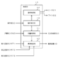
- FIG. 2 is a block diagram showing an example of an electrical configuration in the gas chromatograph of FIG.
- the operation of the gas chromatograph is controlled by a control unit 10 including, for example, a CPU (Central Processing Unit).
- the control unit 10 includes a gas supply unit 30, a power supply device 40, an operation unit 50, a flow rate sensor 60, a first temperature sensor 71, a second temperature sensor 72, and a third temperature sensor 73. Etc. are electrically connected.
- the gas supply unit 30 includes, for example, a gas cylinder and an AFC (electronic flow controller), and supplies a carrier gas to the sample vaporizing chamber 5 through the gas supply channel 6.
- the power supply device 40 is a device that supplies power to each part of the gas chromatograph.
- the operation unit 50 is configured to include, for example, a keyboard or a mouse, and an operator can perform various instruction operations on the gas chromatograph by operating the operation unit 50.
- the flow rate sensor 60 detects the total flow rate of the carrier gas supplied to the sample vaporizing chamber 5.
- the total flow rate of the carrier gas refers to the flow rate of the carrier gas flowing through the column 1, the flow rate of the carrier gas flowing through the purge flow channel 7 (purge flow rate), and the flow rate of the carrier gas flowing through the split flow channel 8 (split flow).
- the first temperature sensor 71 is provided, for example, in the column oven 2 and detects the temperature of the column 1 (the temperature of the column oven 2).
- the second temperature sensor 72 is attached to the detector 4, for example, and detects the temperature of the detector 4.
- the third temperature sensor 73 is attached to, for example, the sample introduction unit 3 and detects the temperature of the sample vaporization chamber 5.
- the control unit 10 functions as a flow rate control unit 11, a power supply control unit 12, an operation reception unit 13, a temperature control unit 14 and the like when the CPU executes a program.
- the flow rate control unit 11 controls the flow rate of the carrier gas supplied to the sample vaporizing chamber 5. Specifically, the flow rate control unit 11 controls the operation of the gas supply unit 30 based on the detection signal from the flow rate sensor 60 to perform a process of bringing the carrier gas flow rate closer to the target flow rate.
- the power supply control unit 12 performs a process of switching the power supply of the gas chromatograph. Specifically, when the power supply control unit 12 controls the operation of the power supply device 40, an on state in which power is supplied from the power supply device 40 to each part of the gas chromatograph, and an off state in which power supply to each unit is stopped It can be switched to either.
- the operation reception unit 13 performs a process of receiving an instruction operation when an instruction operation is performed on the gas chromatograph using the operation unit 50.
- the operation of the gas chromatograph is stopped using the operation unit 50, and the stop operation is received by the operation receiving unit 13, the flow rate of the carrier gas supplied to the sample vaporizing chamber 5 by the flow rate control unit 11 is set. Processing to decrease is performed.
- the power supply controller 12 performs a process of switching the power supply of the gas chromatograph based on detection signals from the first temperature sensor 71, the second temperature sensor 72, and the third temperature sensor 73. Specifically, in a state where the flow rate of the carrier gas supplied to the sample vaporizing chamber 5 is equal to or lower than the reference flow rate, the temperature of the column 1 is equal to or lower than the first reference temperature, and the temperature of the detector 4 is equal to or lower than the second reference temperature. When the temperature of the sample vaporizing chamber 5 becomes equal to or lower than the third reference temperature, the power source of the gas chromatograph is switched from the on state to the off state.
- the temperature control unit 14 controls each temperature of the column 1, the detector 4, and the sample vaporizing chamber 5. Although only the heater 21 for heating the column 1 is shown in FIG. 1, the detector 4 and the sample vaporizing chamber 5 are also heated by a heater (not shown) during analysis. In addition to these heaters, the temperature control unit 14 controls the operation of the fan 22 and the like, thereby bringing the temperatures of the column 1, the detector 4, and the sample vaporizing chamber 5 close to the target temperature set manually or automatically. I do.
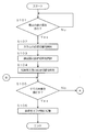
- FIG. 3 is a flowchart showing a processing flow by the control unit 10 when the gas chromatograph is powered off.
- the operator operates the operation unit 50 and the operation reception unit 13 receives an instruction to stop the power supply of the gas chromatograph (Yes in step S101), a process for switching settings related to the column 1 (column setting switching) ), A process for switching settings related to the detector 4 (detector setting switching), and a process for switching settings related to the sample vaporization chamber 5 (sample vaporization chamber setting switching) are started (steps S102 to S104). .
- step S105 it is determined whether or not all the specific criteria are satisfied in the column 1, the detector 4 and the sample vaporizing chamber 5 (step S105).
- This determination is a determination for determining whether or not to switch the power source of the gas chromatograph from the on state to the off state.
- the temperatures of the column 1, the detector 4 and the sample vaporization chamber 5 first to fourth
- a third reference temperature A third reference temperature
- a carrier gas flow rate reference flow rate
- the power controller 12 controls the operation of the power supply device 40, whereby the gas chromatograph power supply is controlled. Are automatically switched from the on state to the off state (step S106). On the other hand, as long as at least one of the above criteria is not satisfied (No in step S105), the corresponding processing in FIGS. 4 to 6 to be described later is repeatedly executed.
- the power-off state of the gas chromatograph includes not only a state where no power is supplied to the gas chromatograph but also a state where very little power is supplied to the gas chromatograph.
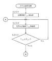
- FIG. 4 is a flowchart showing a mode of column setting switching.
- the target temperature TCT of the column 1 is set by the temperature control unit 14 (step S201).
- Target temperature T CT of the column 1 is the same as one consisting column 1 of the temperature criteria determining the power of a gas chromatograph from the ON state of whether to switch to the off state (first reference temperature), or the first reference The temperature is lower than the temperature.
- step S203 check the temperature T CC column 1 is continuously based on the detection signal from the first temperature sensor 71 (Step S202).
- the determination in step S105 in FIG. 3 is performed. If it is determined in step S105 that all the criteria are not satisfied (No in step S105), the processes in steps S202 to S203 are repeated again.
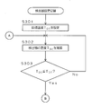
- FIG. 5 is a flowchart showing a detector setting switching mode.
- the target temperature TDT of the detector 4 is set by the temperature control unit 14 (step S301).
- Target temperature T DT detector 4 are the same as one consisting detector 4 temperature criteria determining the power of a gas chromatograph from the ON state of whether to switch to the off state (second reference temperature), or, the 2 Temperature lower than the reference temperature.
- step S303 continuous temperature T DC detector 4 based on the detection signal from the second temperature sensor 72 (Step S302). Then, following the temperature T DC is the target temperature T DT detector 4, that is, when it becomes less than the second reference temperature (Yes at step S303), the determination in step S105 of FIG. 3 are performed. If all the criteria are not satisfied in the determination in step S105 (No in step S105), the processes in steps S302 to S303 are repeated again.
- FIG. 6 is a flowchart showing a mode of sample vaporization chamber setting switching. If the instruction to stop the power supply of the gas chromatograph is performed, the target flow rate F IT of carrier gas is set by the flow control unit 11 (step S401), it is controlled so that the flow rate of the carrier gas approaches the target flow rate F IT.
- the target flow rate F IT of the carrier gas is a flow rate that is smaller than the flow rate of the carrier gas at the time of analysis, and is set to a flow rate that does not damage the column 1 and the detector 4 in a high temperature state.
- the carrier gas flow F IC is continuously confirmed based on the detection signal from the flow sensor 60 until the carrier gas flow F IC becomes equal to or less than the target flow F IT (until Yes in step S403).
- the reference become one carrier gas of determining power of a gas chromatograph from the ON state of whether to switch to the off state the flow (standard flow rate), is described for the case where the same target flow rate F IT
- the target flow rate F IT may be a constant flow rate equal to or less than the reference flow rate.
- the temperature control unit 14 sets the target temperature T IT of the sample vaporizing chamber 5 (step). S404).
- Target temperature T IT of the sample vaporization chamber 5 are the same as the temperature of the sample vaporizing chamber 5 composed one of the criteria for determining the power of a gas chromatograph from the ON state of whether to switch to the off state (third reference temperature), or The temperature is lower than the third reference temperature.
- step S406 the temperature T IC of the sample vaporization chamber 5 based on the detection signal from the third temperature sensor 73 It is continuously confirmed (step S405). Then, the temperature T IC of the sample vaporization chamber 5 is less than the target temperature T IT, that is, when it becomes less than the third reference temperature (Yes at step S406), the determination in step S105 of FIG. 3 are performed. If all the criteria are not satisfied in the determination in step S105 (No in step S105), the processes in steps S405 to S406 are repeated again.
- step S101 when the gas chromatograph power supply is stopped (Yes in step S101), the flow rate of the carrier gas supplied to the sample vaporizing chamber 5 is reduced (steps S401 to S403).
- the temperature of the column 1, the detector 4 and the sample vaporizing chamber 5 is sufficiently lowered (steps S201 to S203, S301 to S303, S404 to S406), and the gas chromatograph is switched from the on state to the off state. (Step S106).
- the flow rate of the carrier gas when the gas chromatograph is powered off, the consumption amount of the carrier gas can be effectively reduced.
- the column 1 and the detector 4 can always be filled with the carrier gas at room temperature. It is possible to prevent the column 1 and the detector 4 from being damaged at a high temperature.
- the power of the gas chromatograph is switched from the ON state to the OFF state after the temperature of the column 1 and the detector 4 is sufficiently lowered, the column 1 and the detector 4 are prevented from being damaged even after the switch is switched to the OFF state. can do. By performing such control automatically, it is possible to reduce the trouble of manually setting parameters by an operator and to prevent damage to the column 1 and the detector 4 due to setting errors.
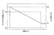
- FIG. 7 is a diagram showing an example of changes in the temperature of the column 1 and the flow rate of the carrier gas.
- the gas chromatograph is turned off.
- the flow rate of the carrier gas is reduced from 40 ml / min to 20 ml / min which is lower than the reference flow rate.
- the target temperature of the column 1 is set to the same or lower temperature than 35 ° C. (second reference temperature), so that the temperature of the column 1 Gradually decreases.
- the gas chromatograph power supply is switched from the on state to the off state when all other criteria (such as the temperature of the column 1 and the sample vaporization chamber 5) are satisfied. Then, the supply of the carrier gas is stopped.
- the consumption amount of the carrier gas is large as shown by a two-dot chain line in FIG. Become.
- the flow rate of the carrier gas is rapidly reduced to a reference flow rate or less when the gas chromatograph power supply is turned off as in this embodiment, the consumption amount of the carrier gas is effectively reduced. be able to.
- FIG. 8 is a flowchart showing a modification of sample vaporization chamber setting switching.
- FIG. 9 is a diagram showing an example of changes in the temperature of the column 1 and the flow rate of the carrier gas in the modification of FIG.
- the target flow rate of the carrier gas is not reduced rapidly to a constant flow rate below the reference flow rate, but gradually reduced to a flow rate below the reference flow rate. It is like that.
- the number of stages N when the flow rate of the carrier gas is decreased stepwise can be set in advance to an arbitrary value, for example, when the operator operates the operation unit 50.
- step S503 until the temperature T CC column 1 is switched reference temperature T 1 (until Yes at step S505), based on the detection signal from the second temperature sensor 72
- the temperature TCC of the column 1 is continuously confirmed (step S504).
- the carrier gas target flow rate F IC is decreased by setting the target flow rate F 1 of the carrier gas.
- step S406 the temperature T IC of the sample vaporization chamber 5 based on the detection signal from the third temperature sensor 73 It is continuously confirmed (step S405). Then, the temperature T IC of the sample vaporization chamber 5 is less than the target temperature T IT, that is, when it becomes less than the third reference temperature (Yes at step S406), the determination in step S105 of FIG. 3 are performed. If all the criteria are not satisfied in the determination in step S105 (No in step S105), the processes in steps S405 to S406 are repeated again.
- the flow rate of the carrier gas gradually decreases to the reference flow rate or lower, so that the temperature of the column 1 and the detector 4 is lowered.
- the flow rate of the carrier gas can be gradually reduced.
- Carrier gas consumption can be effectively reduced.
- FIG. 10 is a flowchart showing the flow of processing by the control unit 10 when there is no instruction operation to the gas chromatograph.
- the power source of the gas chromatograph When the power source of the gas chromatograph is on, it is monitored whether or not a certain period of time elapses without the operator operating the operation unit 50.
- the target temperature TCT of the column 1 is automatically set by the temperature control unit 14 while maintaining the supply of the carrier gas into the column 1 (step S603).
- the target temperature TCT of the column 1 set at this time is a temperature lower than the temperature of the column 1 at the time of analysis, and is a temperature at which damage to the column 1 such as bleed does not occur even if maintained at that temperature for a long time. (For example, room temperature).
- the temperature of the column 1 is automatically reduced, so that the column 1 is effectively prevented from being damaged. be able to.
- the process as shown in FIG. 10 can also be applied to a gas chromatograph in which the processes as shown in FIGS. 3 to 6 and FIG. 8 are not performed.
- the temperature of the column 1 is equal to or lower than the first reference temperature
- the temperature of the detector 4 is equal to the second reference temperature.
- a configuration has been described in which the gas chromatograph power supply is switched from the on state to the off state when the temperature of the sample vaporizing chamber 5 is equal to or lower than the third reference temperature.
- the configuration is not limited to such a configuration, and a configuration in which the temperature of the sample vaporizing chamber 5 is not used as a reference may be used.
- the gas chromatograph power supply may be switched from the on state to the off state.
Landscapes
- Physics & Mathematics (AREA)
- Health & Medical Sciences (AREA)
- Life Sciences & Earth Sciences (AREA)
- Chemical & Material Sciences (AREA)
- Analytical Chemistry (AREA)
- Biochemistry (AREA)
- General Health & Medical Sciences (AREA)
- General Physics & Mathematics (AREA)
- Immunology (AREA)
- Pathology (AREA)
- Other Investigation Or Analysis Of Materials By Electrical Means (AREA)
Abstract
Description
T1=435-80=355℃
T2=355-80=275℃
T3=275-80=195℃
T4=195-80=115℃
T5=115-80=35℃
2 カラムオーブン
3 試料導入部
4 検出器
5 試料気化室
6 ガス供給流路
7 パージ流路
8 スプリット流路
10 制御部
11 流量制御部
12 電源制御部
13 操作受付部
14 温度制御部
21 ヒータ
22 ファン
30 ガス供給部
40 電源装置
50 操作部
60 流量センサ
71 第1温度センサ
72 第2温度センサ
73 第3温度センサ
Claims (5)
- 試料気化室において気化された試料をキャリアガスとともにカラム内に導入し、前記カラム内を通過する過程で分離された試料成分を検出器で検出するガスクロマトグラフであって、
前記カラムの温度を検出する第1温度センサと、
前記検出器の温度を検出する第2温度センサと、
前記試料気化室に供給するキャリアガスの流量を制御する流量制御部と、
前記ガスクロマトグラフに対する指示操作を受け付ける操作受付部と、
前記ガスクロマトグラフの電源を切り替える電源制御部とを備え、
前記流量制御部は、前記操作受付部により前記ガスクロマトグラフの電源の停止操作が受け付けられた場合に、前記試料気化室に供給するキャリアガスの流量を減少させ、
前記電源制御部は、前記試料気化室に供給されるキャリアガスの流量が基準流量以下となった状態で、前記第1温度センサにより検出される前記カラムの温度が第1基準温度以下となり、かつ、前記第2温度センサにより検出される前記検出器の温度が第2基準温度以下となった場合に、前記ガスクロマトグラフの電源をオン状態からオフ状態に切り替えることを特徴とするガスクロマトグラフ。 - 前記試料気化室の温度を検出する第3温度センサをさらに備え、
前記電源制御部は、前記試料気化室に供給されるキャリアガスの流量が基準流量以下となった状態で、前記第1温度センサにより検出される前記カラムの温度が第1基準温度以下となり、前記第2温度センサにより検出される前記検出器の温度が第2基準温度以下となり、かつ、前記第3温度センサにより検出される前記試料気化室の温度が第3基準温度以下となった場合に、前記ガスクロマトグラフの電源をオン状態からオフ状態に切り替えることを特徴とする請求項1に記載のガスクロマトグラフ。 - 前記流量制御部は、前記操作受付部により前記ガスクロマトグラフの電源の停止操作が受け付けられた場合に、前記試料気化室に供給するキャリアガスの目標流量を前記基準流量以下の一定の流量に設定することを特徴とする請求項1又は2に記載のガスクロマトグラフ。
- 前記流量制御部は、前記操作受付部により前記ガスクロマトグラフの電源の停止操作が受け付けられた場合に、前記第1温度センサにより検出される前記カラムの温度に基づいて、前記試料気化室に供給するキャリアガスの目標流量を前記基準流量以下の流量まで段階的に減少させることを特徴とする請求項1又は2に記載のガスクロマトグラフ。
- 前記ガスクロマトグラフの電源がオン状態のときに、前記操作受付部により前記ガスクロマトグラフに対する指示操作が受け付けられないまま一定時間が経過した場合に、前記カラムの目標温度を自動的に低下させる温度制御部とをさらに備えたことを特徴とする請求項1~4のいずれかに記載のガスクロマトグラフ。
Priority Applications (4)
| Application Number | Priority Date | Filing Date | Title |
|---|---|---|---|
| PCT/JP2015/051990 WO2016120963A1 (ja) | 2015-01-26 | 2015-01-26 | ガスクロマトグラフ |
| US15/541,935 US10591452B2 (en) | 2015-01-26 | 2015-01-26 | Gas chromatograph |
| JP2016571515A JP6428793B2 (ja) | 2015-01-26 | 2015-01-26 | ガスクロマトグラフ |
| CN201580073639.5A CN107110830B (zh) | 2015-01-26 | 2015-01-26 | 气相色谱仪 |
Applications Claiming Priority (1)
| Application Number | Priority Date | Filing Date | Title |
|---|---|---|---|
| PCT/JP2015/051990 WO2016120963A1 (ja) | 2015-01-26 | 2015-01-26 | ガスクロマトグラフ |
Publications (1)
| Publication Number | Publication Date |
|---|---|
| WO2016120963A1 true WO2016120963A1 (ja) | 2016-08-04 |
Family
ID=56542623
Family Applications (1)
| Application Number | Title | Priority Date | Filing Date |
|---|---|---|---|
| PCT/JP2015/051990 Ceased WO2016120963A1 (ja) | 2015-01-26 | 2015-01-26 | ガスクロマトグラフ |
Country Status (4)
| Country | Link |
|---|---|
| US (1) | US10591452B2 (ja) |
| JP (1) | JP6428793B2 (ja) |
| CN (1) | CN107110830B (ja) |
| WO (1) | WO2016120963A1 (ja) |
Cited By (2)
| Publication number | Priority date | Publication date | Assignee | Title |
|---|---|---|---|---|
| JP2020186979A (ja) * | 2019-05-13 | 2020-11-19 | 株式会社島津製作所 | クロマトグラフィー分析システム |
| US11885776B2 (en) | 2021-10-26 | 2024-01-30 | Shimadzu Corporation | Chromatography analysis system |
Families Citing this family (8)
| Publication number | Priority date | Publication date | Assignee | Title |
|---|---|---|---|---|
| US10458961B2 (en) * | 2017-08-01 | 2019-10-29 | Shimadzu Corporation | Gas chromatograph |
| CN111157663A (zh) * | 2018-11-08 | 2020-05-15 | 中国石油化工股份有限公司 | 一种总烃浓度监测设备 |
| US20220011280A1 (en) * | 2018-11-20 | 2022-01-13 | Hitachi High-Tech Corporation | Analysis Apparatus Having a Plurality of Chromatographs and Controlling Method Thereof |
| CN114047276B (zh) * | 2022-01-17 | 2022-04-15 | 华谱科仪(北京)科技有限公司 | 色谱仪控制方法及装置 |
| IT202200021486A1 (it) * | 2022-10-18 | 2024-04-18 | Socrate S P A | Metodo per ridurre le emissioni continue in un processo di analisi gascromatografica |
| JP2024059502A (ja) * | 2022-10-18 | 2024-05-01 | 株式会社島津製作所 | ガスクロマトグラフ支援装置およびガスクロマトグラフ支援方法 |
| DE102023133182A1 (de) * | 2023-11-28 | 2025-05-28 | Alivion AG | Gasdetektionsvorrichtung mit temperaturabhängiger Flussratensteuerung und Verfahren zur Bestimmung einer chemischen Verbindung mittels einer solchen Gasdetektionsvorrichtung |
| CN119936277B (zh) * | 2025-03-12 | 2025-09-05 | 宁波润博仪表科技有限公司 | 一种用于过程气相色谱仪的液体进样控制装置 |
Citations (3)
| Publication number | Priority date | Publication date | Assignee | Title |
|---|---|---|---|---|
| JPS5546217U (ja) * | 1978-09-19 | 1980-03-26 | ||
| JPH04138359A (ja) * | 1990-09-28 | 1992-05-12 | Shimadzu Corp | ガスクロマトグラフ |
| JP2000304751A (ja) * | 1999-04-16 | 2000-11-02 | Shimadzu Corp | 自動分析装置 |
Family Cites Families (8)
| Publication number | Priority date | Publication date | Assignee | Title |
|---|---|---|---|---|
| US5508204A (en) * | 1995-01-12 | 1996-04-16 | Norman Clinical Laboratories, Inc. | Multiple sample sequential chemical analysis |
| JP3204106B2 (ja) | 1996-07-31 | 2001-09-04 | 株式会社島津製作所 | 測定装置 |
| US6148657A (en) * | 1996-08-13 | 2000-11-21 | Suzuki Motor Corporation | Method and apparatus for analyzing a breath sample |
| JP4267291B2 (ja) * | 2002-10-21 | 2009-05-27 | 新日本製鐵株式会社 | 軽油回収装置の熱交換器の洗浄方法 |
| JP5206646B2 (ja) * | 2009-10-29 | 2013-06-12 | 株式会社島津製作所 | ガスクロマトグラフ装置 |
| US8591630B2 (en) * | 2010-10-06 | 2013-11-26 | Aviv Amirav | Fast gas chromatograph method and device for analyzing a sample |
| JP5682506B2 (ja) * | 2011-08-24 | 2015-03-11 | 株式会社島津製作所 | ガスクロマトグラフ装置 |
| JP2014185953A (ja) * | 2013-03-25 | 2014-10-02 | Shimadzu Corp | ガスクロマトグラフ装置 |
-
2015
- 2015-01-26 CN CN201580073639.5A patent/CN107110830B/zh not_active Expired - Fee Related
- 2015-01-26 US US15/541,935 patent/US10591452B2/en active Active
- 2015-01-26 JP JP2016571515A patent/JP6428793B2/ja not_active Expired - Fee Related
- 2015-01-26 WO PCT/JP2015/051990 patent/WO2016120963A1/ja not_active Ceased
Patent Citations (3)
| Publication number | Priority date | Publication date | Assignee | Title |
|---|---|---|---|---|
| JPS5546217U (ja) * | 1978-09-19 | 1980-03-26 | ||
| JPH04138359A (ja) * | 1990-09-28 | 1992-05-12 | Shimadzu Corp | ガスクロマトグラフ |
| JP2000304751A (ja) * | 1999-04-16 | 2000-11-02 | Shimadzu Corp | 自動分析装置 |
Cited By (3)
| Publication number | Priority date | Publication date | Assignee | Title |
|---|---|---|---|---|
| JP2020186979A (ja) * | 2019-05-13 | 2020-11-19 | 株式会社島津製作所 | クロマトグラフィー分析システム |
| JP7226077B2 (ja) | 2019-05-13 | 2023-02-21 | 株式会社島津製作所 | クロマトグラフィー分析システム |
| US11885776B2 (en) | 2021-10-26 | 2024-01-30 | Shimadzu Corporation | Chromatography analysis system |
Also Published As
| Publication number | Publication date |
|---|---|
| CN107110830B (zh) | 2019-11-22 |
| JP6428793B2 (ja) | 2018-11-28 |
| JPWO2016120963A1 (ja) | 2017-07-20 |
| US20170356890A1 (en) | 2017-12-14 |
| US10591452B2 (en) | 2020-03-17 |
| CN107110830A (zh) | 2017-08-29 |
Similar Documents
| Publication | Publication Date | Title |
|---|---|---|
| JP6428793B2 (ja) | ガスクロマトグラフ | |
| JP6314989B2 (ja) | ガスクロマトグラフ質量分析装置 | |
| JP5206646B2 (ja) | ガスクロマトグラフ装置 | |
| US9759695B2 (en) | Column oven and liquid chromatograph | |
| US9435774B2 (en) | Gas chromatograph apparatus | |
| EP3018474B1 (en) | Method for operating a gas chromatography system with a vacuum system | |
| US20180238840A1 (en) | Gas chromatograph | |
| JP6642271B2 (ja) | ガスクロマトグラフ装置 | |
| JP2014185953A (ja) | ガスクロマトグラフ装置 | |
| US10794875B2 (en) | Gas chromatograph | |
| JP2015155837A (ja) | 液体クロマトグラフとそれに用いるカラムオーブン | |
| JP6079612B2 (ja) | ガスクロマトグラフ | |
| CN113242969B (zh) | 气相色谱仪、维护切换模式设定方法以及存储有维护切换模式设定程序的计算机可读取介质 | |
| JP4179189B2 (ja) | ガスクロマトグラフ装置 | |
| JP6669265B2 (ja) | ガスクロマトグラフ | |
| JP6769389B2 (ja) | ガス供給制御装置、ガスクロマトグラフ及び圧力センサ異常判定方法 | |
| JP2018197669A (ja) | ガスクロマトグラフ装置 | |
| WO2019207850A1 (ja) | クロマトグラフィー分析システム | |
| WO2016051554A1 (ja) | ガスクロマトグラフ質量分析装置 | |
| WO2020129137A1 (ja) | ガスクロマトグラフ、メンテナンスモード設定方法およびメンテナンスモード設定プログラム | |
| JP2021039062A (ja) | 熱分析装置 | |
| JP2000352560A (ja) | 熱分析装置 |
Legal Events
| Date | Code | Title | Description |
|---|---|---|---|
| 121 | Ep: the epo has been informed by wipo that ep was designated in this application |
Ref document number: 15879860 Country of ref document: EP Kind code of ref document: A1 |
|
| ENP | Entry into the national phase |
Ref document number: 2016571515 Country of ref document: JP Kind code of ref document: A |
|
| WWE | Wipo information: entry into national phase |
Ref document number: 15541935 Country of ref document: US |
|
| NENP | Non-entry into the national phase |
Ref country code: DE |
|
| 122 | Ep: pct application non-entry in european phase |
Ref document number: 15879860 Country of ref document: EP Kind code of ref document: A1 |