WO2016120960A1 - タイヤ加硫装置 - Google Patents
タイヤ加硫装置 Download PDFInfo
- Publication number
- WO2016120960A1 WO2016120960A1 PCT/JP2015/051979 JP2015051979W WO2016120960A1 WO 2016120960 A1 WO2016120960 A1 WO 2016120960A1 JP 2015051979 W JP2015051979 W JP 2015051979W WO 2016120960 A1 WO2016120960 A1 WO 2016120960A1
- Authority
- WO
- WIPO (PCT)
- Prior art keywords
- heater
- tire
- bladder
- shielding member
- heat
- Prior art date
Links
Images


Classifications
-
- B—PERFORMING OPERATIONS; TRANSPORTING
- B29—WORKING OF PLASTICS; WORKING OF SUBSTANCES IN A PLASTIC STATE IN GENERAL
- B29D—PRODUCING PARTICULAR ARTICLES FROM PLASTICS OR FROM SUBSTANCES IN A PLASTIC STATE
- B29D30/00—Producing pneumatic or solid tyres or parts thereof
- B29D30/06—Pneumatic tyres or parts thereof (e.g. produced by casting, moulding, compression moulding, injection moulding, centrifugal casting)
- B29D30/0601—Vulcanising tyres; Vulcanising presses for tyres
- B29D30/0662—Accessories, details or auxiliary operations
-
- B—PERFORMING OPERATIONS; TRANSPORTING
- B29—WORKING OF PLASTICS; WORKING OF SUBSTANCES IN A PLASTIC STATE IN GENERAL
- B29C—SHAPING OR JOINING OF PLASTICS; SHAPING OF MATERIAL IN A PLASTIC STATE, NOT OTHERWISE PROVIDED FOR; AFTER-TREATMENT OF THE SHAPED PRODUCTS, e.g. REPAIRING
- B29C33/00—Moulds or cores; Details thereof or accessories therefor
- B29C33/02—Moulds or cores; Details thereof or accessories therefor with incorporated heating or cooling means
-
- B—PERFORMING OPERATIONS; TRANSPORTING
- B29—WORKING OF PLASTICS; WORKING OF SUBSTANCES IN A PLASTIC STATE IN GENERAL
- B29C—SHAPING OR JOINING OF PLASTICS; SHAPING OF MATERIAL IN A PLASTIC STATE, NOT OTHERWISE PROVIDED FOR; AFTER-TREATMENT OF THE SHAPED PRODUCTS, e.g. REPAIRING
- B29C35/00—Heating, cooling or curing, e.g. crosslinking or vulcanising; Apparatus therefor
- B29C35/02—Heating or curing, e.g. crosslinking or vulcanizing during moulding, e.g. in a mould
- B29C35/08—Heating or curing, e.g. crosslinking or vulcanizing during moulding, e.g. in a mould by wave energy or particle radiation
- B29C35/0805—Heating or curing, e.g. crosslinking or vulcanizing during moulding, e.g. in a mould by wave energy or particle radiation using electromagnetic radiation
-
- B—PERFORMING OPERATIONS; TRANSPORTING
- B29—WORKING OF PLASTICS; WORKING OF SUBSTANCES IN A PLASTIC STATE IN GENERAL
- B29D—PRODUCING PARTICULAR ARTICLES FROM PLASTICS OR FROM SUBSTANCES IN A PLASTIC STATE
- B29D30/00—Producing pneumatic or solid tyres or parts thereof
- B29D30/06—Pneumatic tyres or parts thereof (e.g. produced by casting, moulding, compression moulding, injection moulding, centrifugal casting)
- B29D30/0601—Vulcanising tyres; Vulcanising presses for tyres
- B29D30/0654—Flexible cores therefor, e.g. bladders, bags, membranes, diaphragms
-
- B—PERFORMING OPERATIONS; TRANSPORTING
- B29—WORKING OF PLASTICS; WORKING OF SUBSTANCES IN A PLASTIC STATE IN GENERAL
- B29C—SHAPING OR JOINING OF PLASTICS; SHAPING OF MATERIAL IN A PLASTIC STATE, NOT OTHERWISE PROVIDED FOR; AFTER-TREATMENT OF THE SHAPED PRODUCTS, e.g. REPAIRING
- B29C35/00—Heating, cooling or curing, e.g. crosslinking or vulcanising; Apparatus therefor
- B29C35/02—Heating or curing, e.g. crosslinking or vulcanizing during moulding, e.g. in a mould
- B29C35/08—Heating or curing, e.g. crosslinking or vulcanizing during moulding, e.g. in a mould by wave energy or particle radiation
- B29C35/0805—Heating or curing, e.g. crosslinking or vulcanizing during moulding, e.g. in a mould by wave energy or particle radiation using electromagnetic radiation
- B29C2035/0822—Heating or curing, e.g. crosslinking or vulcanizing during moulding, e.g. in a mould by wave energy or particle radiation using electromagnetic radiation using IR radiation
-
- B—PERFORMING OPERATIONS; TRANSPORTING
- B29—WORKING OF PLASTICS; WORKING OF SUBSTANCES IN A PLASTIC STATE IN GENERAL
- B29D—PRODUCING PARTICULAR ARTICLES FROM PLASTICS OR FROM SUBSTANCES IN A PLASTIC STATE
- B29D30/00—Producing pneumatic or solid tyres or parts thereof
- B29D30/06—Pneumatic tyres or parts thereof (e.g. produced by casting, moulding, compression moulding, injection moulding, centrifugal casting)
- B29D30/0601—Vulcanising tyres; Vulcanising presses for tyres
- B29D30/0662—Accessories, details or auxiliary operations
- B29D2030/0666—Heating by using fluids
- B29D2030/0674—Heating by using non-fluid means, e.g. electrical heating
-
- B—PERFORMING OPERATIONS; TRANSPORTING
- B29—WORKING OF PLASTICS; WORKING OF SUBSTANCES IN A PLASTIC STATE IN GENERAL
- B29K—INDEXING SCHEME ASSOCIATED WITH SUBCLASSES B29B, B29C OR B29D, RELATING TO MOULDING MATERIALS OR TO MATERIALS FOR MOULDS, REINFORCEMENTS, FILLERS OR PREFORMED PARTS, e.g. INSERTS
- B29K2105/00—Condition, form or state of moulded material or of the material to be shaped
- B29K2105/24—Condition, form or state of moulded material or of the material to be shaped crosslinked or vulcanised
- B29K2105/246—Uncured, e.g. green
Definitions
- the present invention relates to a tire vulcanizer.
- a heating unit that is disposed at the outer peripheral position of the center post on the tire inner peripheral side of the raw tire and imparts heat to the raw tire;
- a central mechanism is disclosed that includes a moving means movable to a position.
- One aspect of the present invention is a vertically movable center post partially inserted into a raw tire, and the raw post is fixed to the center post and disposed inside the raw tire from the inside of the raw tire by radiant heat.
- a tire vulcanizing apparatus including a heating unit that transfers heat to a tire. Since the tire vulcanizing apparatus of the above aspect has a configuration in which the heating unit is fixed to the center post, the raw tire can be heated using radiant heat from the inside of the raw tire with a simple configuration.
- the heating unit may include a heater that emits the radiant heat, and an openable / closable shielding unit that is interposed between the heater and an inner surface of the green tire and blocks the radiant heat from the heater.
- the state can be switched between a state in which heat from the heater is transmitted to the inner surface of the raw tire and a state in which heat from the heater is not transmitted to the inner surface of the raw tire in accordance with the open / closed state of the shielding portion.
- the shielding portion moves the shielding member between a cylindrical shielding member surrounding the heater, a shielding position where the shielding member surrounds the heater, and a non-shielding position where the heater is located outside the shielding member. And a moving mechanism to be moved. In this case, when the shielding member is in a shielding position surrounding the heater, the heat of the heater is blocked by the shielding member and does not reach the raw tire. Moreover, when the moving mechanism moves the shielding member, the open / close state of the shielding portion changes.
- the heater may have a plurality of heater members that can move relative to each other, and the plurality of heater members are stored in a stacked state so as to have an outer diameter that can be accommodated in the shielding member;
- the shield member may have an outer diameter that exceeds the inner diameter of the shielding member, and may be movably disposed so as to be in a heat generation state where there is less overlap with each other than in the retracted state. In this case, the heater is small in the retracted state, and when the heater is located outside the shielding member in the heat generation state, the heater members are less overlapped and a large area capable of generating radiant heat can be secured. .
- the tire vulcanizing apparatus of the above aspect may further include a bladder for pressing the inner surface of the green tire, and at this time, the center post may hold the heating unit in the bladder. In this case, the heating unit heats the raw tire through the bladder.
- the tire vulcanizing apparatus may further include a gas supply unit that supplies dry gas into the bladder.
- a gas supply unit that supplies dry gas into the bladder.
- the tire vulcanizing apparatus of the above aspect may further include a water vapor supply unit that supplies water vapor into the bladder.
- a water vapor supply unit that supplies water vapor into the bladder.
- FIG. 1 is a partial cross-sectional view showing a tire vulcanizing apparatus of the present embodiment.
- a tire vulcanizing apparatus 1 according to this embodiment shown in FIG. 1 includes a tire mold 2, a bladder 10, a center mechanism 14, a mold fixing mechanism 17, a mold lifting mechanism 18, a tire heating mechanism 20, and a gas supply unit. 26.
- the tire mold 2 includes an upper side mold 3, a lower side mold 4, an upper bead ring 5, a lower bead ring 6, and a tread mold 7.
- the upper side mold 3 and the lower side mold 4 are molds for forming both sidewalls 32 of the tire 30.
- the upper side mold 3 is attached to the mold lifting mechanism 18.
- the lower side mold 4 is attached to the mold fixing mechanism 17.
- the upper bead ring 5 and the lower bead ring 6 are molds for forming both beads 33 of the tire 30.
- the tread mold 7 has a tread segment 8 and a slide segment 9.
- the tread segment 8 is a mold for transferring a tread pattern to the tread portion 31 of the raw tire 30X.
- the slide segment 9 holds the tread segment 8 so that the tread segment 8 can move in the radial direction of the tire 30.
- the slide segment 9 is connected to the mold lifting mechanism 18.
- the structure of the tire mold 2 is not limited to said structure.
- the configuration of the tire mold 2 may be appropriately selected according to the shape of the tire to be produced.
- the bladder 10 is a hollow member for pressing the raw tire 30X disposed in the tire mold 2 against the tire mold 2 from the inside when the tire vulcanizing apparatus 1 is used.
- the bladder 10 includes a main body portion 11 having a shape corresponding to the inner surface shape of the tire 30 vulcanized and formed by the tire vulcanizing device 1 of the present embodiment, and an upper clamp portion 12 and a lower clamp portion connected to the central mechanism 14. 13.
- the bladder 10 presses the inner surface 30b of the raw tire 30X.
- the bladder 10 is heated by a heater 23 described later, and the raw tire 30X can be heated from the inner surface 30b side through the bladder 10.
- the configuration of the bladder 10 is not limited to the above configuration.
- the center mechanism 14 includes a pair of bladder clamp rings 15 connected to the upper clamp portion 12 and the lower clamp portion 13 of the bladder 10 and a center post 16 connected to the pair of bladder clamp rings 15.
- the center mechanism 14 deforms the bladder 10 so that the bladder 10 can be inserted into and removed from the raw tire 30 ⁇ / b> X by relatively moving the pair of bladder clamp rings 15 in the direction of the center line 16 a of the center post 16.
- the center post 16 supports the raw tire 40 ⁇ / b> X attached to the tire mold 2.
- the center post 16 of this embodiment supports the raw tire 40X through the bladder clamp ring 15 and the bladder 10.
- the configuration of the central mechanism 14 is not limited to the above configuration.
- the mold fixing mechanism 17 may be appropriately selected from known configurations that can support the center mechanism 14 and the lower side mold 4.
- the mold lifting mechanism 18 moves the upper side mold 3 and the tread mold 7 forward and backward in the center direction of the center post 16 with respect to the lower side mold 4.
- the slide segment 9 of the tread mold 7 moves toward the center post 16 as the mold lifting mechanism 18 brings the tread mold 7 closer to the mold fixing mechanism 17.
- the structure of the mold raising / lowering mechanism 18 is not limited to said structure.
- the tire heating mechanism 20 is attached to the center post 16 and an external heating mechanism 21 that heats the raw tire 30X from the outer surface 30a side of the raw tire 30X via the upper side mold 3, the lower side mold 4, and the tread mold 7. It has the internal heating mechanism 22 (heating part) which heats the raw tire 30X from the inner surface 30b side of the tire 30X.
- the external heating mechanism 21 has, for example, a high-temperature steam flow path, and heats the raw tire 30X from the outside with the heat of the high-temperature steam.
- the configuration of the external heating mechanism 21 is not limited to the above configuration.
- the internal heating mechanism 22 has a heater 23 attached to the center post 16 and a wiring 25 for supplying electric power to the heater 23.
- the heater 23 heats the tire 30 by radiant heat from the inside of the tire 30 supported by the upper and lower bead rings. In the present embodiment, the heater 23 heats the tire 30 via the bladder 10. In the case of the tire vulcanizing apparatus 1 that does not include the bladder 10, the heater 23 may heat the tire 30 directly from the inside of the tire 30.
- the shape of the heater 23 is a cylindrical shape that surrounds the center post 16 and is coaxial with the center line 16 a of the center post 16.
- a radiating surface 24 that emits radiant heat toward the inner surface of the raw tire 30X is formed.
- the shape of the heater 23 is not limited to a cylindrical shape.
- the heater 23 may have a rectangular tube shape.
- the entire outer peripheral surface of the heater 23 may be the radiation surface 24, or a part of the outer peripheral surface of the heater 23 may be the radiation surface 24.
- the heater 23 a known heat generation method that generates heat when supplied with electric power may be appropriately selected and applied. That is, as the heater 23 of the present embodiment, an infrared heater, a ceramic heater, a carbon heater, or the like may be employed.
- the wavelength of the radiant heat from the heater 23 preferably corresponds to the absorption wavelength characteristic of the bladder 10 and is a wavelength that can efficiently heat the bladder 10.
- An example of a heater that can suitably heat the bladder 10 in accordance with the absorption wavelength characteristics of a resin such as rubber constituting the bladder 10 is an infrared heater having a peak at a wavelength of about 3.5 ⁇ m.
- a ceramic heater has a peak of the wavelength of radiant heat in the range from 3 ⁇ m to 6 ⁇ m, and thus is particularly suitable for the heater 23 of the present embodiment.
- Carbon heaters may have a shorter radiant heat wavelength peak than ceramic heaters, but the time required to rise to the optimum temperature for vulcanization and stabilization is shorter, and than with ceramic heaters. This is effective in that heating at a high temperature is possible.
- the wiring 25 is arranged inside the center post 16 and connects the heater 23 and a power source (not shown).
- the gas supply unit 26 supplies dry gas into the bladder 10 during vulcanization molding of the raw tire 30 ⁇ / b> X, and collects the dry gas after vulcanization molding from the bladder 10.
- the gas supply unit 26 is provided in one or both of the pair of bladder clamp rings 15 and communicates with the inside of the bladder 10 and the dry gas is taken in and out through the gas conduit 27.
- a compressor 28 and a dry gas tank 29 are provided.
- the composition of the dry gas is not particularly limited. For example, nitrogen gas may be employed as the dry gas.
- the raw tire 30 ⁇ / b> X is placed on the lower side mold 4 with the bladder 10 and the heater 23 disposed inside the raw tire 30 ⁇ / b> X. . Furthermore, the tread mold 7 and the upper side mold 3 are attached so as to cover the outer surface 30a of the raw tire 30X.
- the external heating mechanism 21 heats the raw tire 30X from the outer surface 30a of the raw tire 30X via the upper side mold 3, the lower side mold 4, and the tread mold 7. Further, dry gas is supplied into the bladder 10 by the gas supply unit 26 to advance, and the bladder 10 presses the outer surface 30a of the raw tire 30X against the inner surface of the tire mold 2.
- the dry gas supplied into the bladder 10 is heated by the heater 23.
- the bladder 10 is heated by the dry gas heated by the heater 23. Further, the radiant heat from the heater 23 directly reaches the inner surface of the bladder 10 to heat the bladder 10.
- the dry gas filled in the bladder 10 flows in the bladder 10 so as to heat the inner surface of the bladder 10 substantially uniformly. Since the dry gas is in a gaseous state without being liquefied under the operating environment of the tire vulcanizer 1, the gaseous dry gas is flowing in the bladder 10.
- the heated dry gas may be circulated between the bladder 10 and the gas supply unit 26 to generate an air flow in the bladder 10. In this case, the temperature in the bladder 10 can be made more uniform.
- the raw tire 30X is vulcanized in the tire mold 2 by the heater 23 and the external heating mechanism 21.
- the heater 23 fixed to the center post 16 heats the inner surface 30b of the raw tire 30X.
- the raw tire can be heated using radiant heat.
- FIG. 2 is a partial cross-sectional view showing a tire vulcanizing apparatus according to this modification.
- a water vapor supply unit 40 that supplies water vapor into the bladder 10 is provided instead of the gas supply unit 26 described above.
- the water vapor supply unit 40 supplies water vapor to the bladder 10 during vulcanization molding of the raw tire 30X, and collects the water vapor after vulcanization molding from the bladder 10.
- the water vapor supply unit 40 includes a water vapor line 41 provided in one or both of the pair of bladder clamp rings 15 and communicated with the inside of the bladder 10, and a compressor that draws water in and out through the water vapor line 41. 42 and a boiler 43.
- the heater 23 is heating the bladder 10, so The high-temperature water that accumulates again becomes water vapor.
- the heater 23 in this modification also has an effect of maintaining the gas state by directly heating the water vapor so that the water vapor is not liquefied.
- the raw tire 30X can be uniformly heated through the bladder 10 to which the water vapor is supplied.
- FIG. 3 is a partial cross-sectional view showing the tire vulcanizing apparatus of the present embodiment.
- the same reference numerals are given to the same components as those in the first embodiment, and duplicate descriptions are omitted.
- the internal heating mechanism 22 includes the shielding unit 50 and the heater 23 disclosed in the first embodiment.
- the shielding unit 50 includes a cylindrical shielding member 51 surrounding the heater 23 and a moving mechanism 52 that moves the shielding member 51.
- the shielding member 51 is interposed between the heater 23 and the inner surface 30b of the raw tire 30X when located at a position surrounding the heater 23. For this reason, when the shielding member 51 is located at a position surrounding the heater 23, the shielding member 51 shields at least a part of the radiant heat generated by the heater 23, and the heat from the heater 23 is not transmitted to the bladder 10 and the raw tire 30X. So that it is insulated.
- the shape of the shielding member 51 is not particularly limited as long as it surrounds the heater 23.
- the shape of the shielding member 51 is not limited to a cylindrical shape, and may be a rectangular tube shape.
- the shielding member 51 may be capable of blocking the radiant heat generated by the heater 23 in all directions, or may block at least a part of the radiant heat generated by the heater 23.
- the shielding member 51 may be configured to shield the radiant heat from the heater 23 with a wall surface continuous in the circumferential direction around the center line 16 a of the center post 16, or the center line 16 a of the center post 16. A configuration in which a part of the radiant heat from the heater 23 is blocked by a wall surface that is discontinuous in the circumferential direction centering on.
- the moving mechanism 52 includes an actuator (not shown), so that the shielding member 51 is heated between the shielding position P1 where the shielding member 51 surrounds the heater 23 and the non-shielding position P2 where the heater 23 is located outside the shielding member 51. 23 is moved.
- the shielding member 51 is disposed at the non-shielding position P2, so that the heater 23 The bladder 10 and the raw tire 30X are heated by heat in the same manner as in the first embodiment.
- the power supply to the heater 23 is stopped. After the supply of power to the heater 23 is stopped, the heater 23 continues to emit radiant heat due to the residual heat of the heater 23.
- the moving mechanism 52 moves the shielding member 51 to the shielding position P ⁇ b> 1, and the shielding member 51 surrounds the heater 23. Thereby, since heat is trapped in the shielding member 51, heating that leads to overvulcanization of the raw tire 30X is prevented. In a state where the shielding member 51 is at the shielding position P1, the tire 30 after vulcanization molding can be taken out from the tire mold 2 in a state where overvulcanization due to the influence of the residual heat of the heater 23 does not easily occur.
- FIG. 3 A modification of the above embodiment will be described.
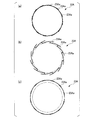
- 4 (a), 4 (b), and 4 (c) are plan views of a heater in the tire vulcanizing apparatus of the present modification.
- a heater 23A having a different configuration from the heater 23 disclosed in the second embodiment is replaced with the heater 23 disclosed in the second embodiment. I have.
- the heater 23A shown in FIG. 4 can be configured in a cylindrical shape by combining a plurality of heater members 23Aa.
- the plurality of heater members 23Aa are shown in FIG. 4 (a) in which a part of the heater members 23Aa is relatively overlapped with each other (stored state, FIG. 4 (a)) and adjacent heater members 23Aa are shown in FIG. 4 (a). It can be deformed so that it can be set to any one of the overlapping states (the state during heat generation, FIG. 4C) rather than such an overlapping (see FIG. 4B). It should be noted that the plurality of heater members 23Aa may be arranged in a state where they are abutted with each other.
- the heater 23A in a state where the heater members 23Aa are partially overlapped with each other, the heater 23A has a cylindrical shape having a diameter that can be accommodated in the shielding member 51.
- the heater 23A in a state where the heater members 23Aa are partially overlapped, or in a state where the adjacent heater members 23Aa are arranged to face each other, the heater 23A
- the cylindrical member has an outer diameter larger than the inner diameter of the shielding member 51.
- the heater 23A can be accommodated inside the shielding member 51, and in a state where the shielding member 51 is not covered and emits radiant heat, the outer periphery has a wider area than when accommodated in the shielding member 51. From the surface, more radiant heat can be emitted toward the bladder 10 than in the case where the heater 23A generates heat in the above-described storage state.
- the present invention can be used for an apparatus for vulcanizing and molding a tire.
Landscapes
- Engineering & Computer Science (AREA)
- Mechanical Engineering (AREA)
- Physics & Mathematics (AREA)
- Health & Medical Sciences (AREA)
- Oral & Maxillofacial Surgery (AREA)
- Thermal Sciences (AREA)
- Electromagnetism (AREA)
- Toxicology (AREA)
- Moulds For Moulding Plastics Or The Like (AREA)
- Heating, Cooling, Or Curing Plastics Or The Like In General (AREA)
Abstract
Description
本発明は、上記の課題に鑑みてなされたものであり、簡易な構成により生タイヤの内側から放射熱を用いて生タイヤを加熱可能なタイヤ加硫装置を提供することを目的とする。
上記態様のタイヤ加硫装置は、センターポストに加熱部が固定される構成であるので、簡易な構成により生タイヤの内側から放射熱を用いて生タイヤを加熱可能である。
この場合、遮蔽部における開閉状態に応じて、生タイヤの内面にヒータからの熱が伝達される状態と、生タイヤの内面にヒータからの熱が伝達されない状態とに切替可能である。
この場合、遮蔽部材がヒータを囲む遮蔽位置にあるときには、ヒータの熱は遮蔽部材に遮られて生タイヤに到達しない。また、遮蔽部材を移動機構が移動させることによって、遮蔽部における開閉状態が変化する。
この場合、格納状態ではヒータが小型であり、発熱時状態において遮蔽部材外にヒータが位置している時にはヒータ部材同士の重なりが少なく放射熱を発することが可能な面積を広く確保することができる。
この場合、加熱部はブラダを介して生タイヤを加熱する。
この場合、ドライガスはブラダ内で液化せずに気体状態であるので、ブラダ内の温度が均一になりやすい。
この場合、加熱部によるブラダの加熱により水蒸気が液化しにくくなるので、ブラダ内の温度が均一になりやすい。
本発明の第1実施形態について説明する。図1は、本実施形態のタイヤ加硫装置を示す部分断面図である。
図1に示す本実施形態のタイヤ加硫装置1は、タイヤモールド2と、ブラダ10と、中心機構14と、モールド固定機構17と、モールド昇降機構18と、タイヤ加熱機構20と、ガス供給部26とを備える。
トレッドセグメント8は、生タイヤ30Xのトレッド部31に対してトレッドパターンを転写する金型である。
スライドセグメント9は、タイヤ30の径方向にトレッドセグメント8が移動可能となるようにトレッドセグメント8を保持する。スライドセグメント9は、モールド昇降機構18に連結されている。
なお、タイヤモールド2の構成は上記の構成には限定されない。たとえば、タイヤモールド2の構成は、生産されるタイヤの形状等に対応して適宜選択されてよい。
なお、ブラダ10の構成は上記の構成には限定されない。
センターポスト16は、タイヤモールド2に取り付けられる生タイヤ40Xを支持する。本実施形態のセンターポスト16は、ブラダクランプリング15及びブラダ10を介して生タイヤ40Xを支持する。
なお、中心機構14の構成は上記の構成には限定されない。
なお、モールド昇降機構18の構成は上記の構成には限定されない。
ドライガスの組成は特に限定されない。たとえば、ドライガスとして窒素ガスが採用されてよい。
本実施形態のタイヤ加硫装置1の使用時には、図1に示すように、生タイヤ30Xの内部にブラダ10及びヒータ23が配された状態で生タイヤ30Xが下サイドモールド4に載置される。さらに、トレッドモールド7及び上サイドモールド3が生タイヤ30Xの外面30aを覆うように取り付けられる。
ブラダ10が加熱されると、ブラダ10から生タイヤ30Xの内面に熱が伝わり、生タイヤ30Xの内面30bから生タイヤ30Xが加熱される。
次に、上記実施形態の変形例について説明する。図2は、本変形例のタイヤ加硫装置を示す部分断面図である。
本変形例では、上記のガス供給部26に代えて、水蒸気をブラダ10内に供給する水蒸気供給部40を備えている。
本変形例では水蒸気が液化せずにブラダ10内を流動するので、水蒸気が供給されるブラダ10を介した生タイヤ30Xの加熱を均一に行うことができる。
本発明の第2実施形態について説明する。図3は、本実施形態のタイヤ加硫装置を示す部分断面図である。なお、本実施形態及びその変形例において、上記第1実施形態と共通の構成要素には同一の符号が付され、重複する説明は省略されている。
上記実施形態の変形例について説明する。図4(a)(b)(c)は、本変形例のタイヤ加硫装置におけるヒータの平面図である。
本変形例のタイヤ加硫装置1A(図3参照)は、上記第2実施形態に開示されたヒータ23とは構成が異なるヒータ23Aを、上記第2実施形態に開示されたヒータ23に代えて備えている。
2 タイヤモールド
3 上サイドモールド
4 下サイドモールド
5 上ビードリング
6 下ビードリング
7 トレッドモールド
8 トレッドセグメント
9 スライドセグメント
10 ブラダ
11 本体部
12 上部クランプ部
13 下部クランプ部
14 中心機構
15 ブラダクランプリング
16 センターポスト
17 モールド固定機構
18 モールド昇降機構
20 タイヤ加熱機構
21 外部加熱機構
22 内部加熱機構
23 ヒータ
24 放射面
25 配線
26 ガス供給部
27 ガス管路
28 コンプレッサ
29 ドライガスタンク
30 タイヤ
30X 生タイヤ
31 トレッド部
32 サイドウォール
33 ビード
40 水蒸気供給部
41 水蒸気管路
42 コンプレッサ
43 ボイラ
50,50A 遮蔽部
51 遮蔽部材
52 移動機構
Claims (7)
- 生タイヤを支持する昇降可能なセンターポストと、
前記センターポストに固定され前記生タイヤの内部に配され放射熱により前記生タイヤの内側から前記生タイヤに熱を伝達する加熱部と、
を備えるタイヤ加硫装置。 - 前記加熱部が、
前記放射熱を発するヒータと、
前記ヒータと前記生タイヤの内面との間に介在され前記ヒータからの放射熱を遮る移動可能な遮蔽部と、
を備える請求項1に記載のタイヤ加硫装置。 - 前記遮蔽部が、
前記ヒータを囲む筒状をなす遮蔽部材と、
前記遮蔽部材が前記ヒータを囲む遮蔽位置と前記遮蔽部材外に前記ヒータが位置する非遮蔽位置との間で前記遮蔽部材を移動させる移動機構と、
を備える請求項2に記載のタイヤ加硫装置。 - 前記ヒータが、相対移動可能な複数のヒータ部材を有し、
前記複数のヒータ部材が、前記遮蔽部材内に収容可能な外径となるように互いに重ねられた格納状態と、前記遮蔽部材の内径を超える外径を有して前記格納状態よりも互いの重なりが少ない発熱時状態とのいずれかとなるように移動可能に配されている
請求項3に記載のタイヤ加硫装置。 - 前記生タイヤの内面を押圧するためのブラダをさらに備え、
前記センターポストが、前記加熱部を前記ブラダ内に保持する
請求項1から4のいずれか一項に記載のタイヤ加硫装置。 - 前記ブラダ内にドライガスを供給するガス供給部をさらに備える請求項5に記載のタイヤ加硫装置。
- 前記ブラダ内に水蒸気を供給する水蒸気供給部をさらに備える請求項5に記載のタイヤ加硫装置。
Priority Applications (5)
| Application Number | Priority Date | Filing Date | Title |
|---|---|---|---|
| CN201580074453.1A CN107206637A (zh) | 2015-01-26 | 2015-01-26 | 轮胎硫化装置 |
| JP2016530020A JP6149160B2 (ja) | 2015-01-26 | 2015-01-26 | タイヤ加硫装置 |
| EP15871301.6A EP3103610A4 (en) | 2015-01-26 | 2015-01-26 | Tire vulcanizer |
| US15/108,469 US9713907B2 (en) | 2015-01-26 | 2015-01-26 | Tire vulcanizing apparatus |
| PCT/JP2015/051979 WO2016120960A1 (ja) | 2015-01-26 | 2015-01-26 | タイヤ加硫装置 |
Applications Claiming Priority (1)
| Application Number | Priority Date | Filing Date | Title |
|---|---|---|---|
| PCT/JP2015/051979 WO2016120960A1 (ja) | 2015-01-26 | 2015-01-26 | タイヤ加硫装置 |
Publications (1)
| Publication Number | Publication Date |
|---|---|
| WO2016120960A1 true WO2016120960A1 (ja) | 2016-08-04 |
Family
ID=56542620
Family Applications (1)
| Application Number | Title | Priority Date | Filing Date |
|---|---|---|---|
| PCT/JP2015/051979 WO2016120960A1 (ja) | 2015-01-26 | 2015-01-26 | タイヤ加硫装置 |
Country Status (5)
| Country | Link |
|---|---|
| US (1) | US9713907B2 (ja) |
| EP (1) | EP3103610A4 (ja) |
| JP (1) | JP6149160B2 (ja) |
| CN (1) | CN107206637A (ja) |
| WO (1) | WO2016120960A1 (ja) |
Families Citing this family (1)
| Publication number | Priority date | Publication date | Assignee | Title |
|---|---|---|---|---|
| CN108016057A (zh) * | 2017-12-28 | 2018-05-11 | 山东豪迈机械科技股份有限公司 | 一种轮胎活络模具 |
Citations (7)
| Publication number | Priority date | Publication date | Assignee | Title |
|---|---|---|---|---|
| JPH05104541A (ja) * | 1991-10-15 | 1993-04-27 | Bridgestone Corp | 生タイヤの加硫方法 |
| JPH09123172A (ja) * | 1995-11-01 | 1997-05-13 | Kobe Steel Ltd | タイヤ加硫方法及びタイヤ加硫機の中心機構 |
| JP2001322128A (ja) * | 2000-05-15 | 2001-11-20 | Kobe Steel Ltd | 加硫機 |
| JP2002018857A (ja) * | 2000-07-13 | 2002-01-22 | Kobe Steel Ltd | 中心機構 |
| JP2006062213A (ja) * | 2004-08-27 | 2006-03-09 | Bridgestone Corp | 生タイヤの予熱方法および装置 |
| JP2011116062A (ja) * | 2009-12-04 | 2011-06-16 | Yokohama Rubber Co Ltd:The | 空気入りタイヤの加硫方法および加硫装置 |
| JP2012218299A (ja) * | 2011-04-08 | 2012-11-12 | Yokohama Rubber Co Ltd:The | 空気入りタイヤの加硫装置 |
Family Cites Families (7)
| Publication number | Priority date | Publication date | Assignee | Title |
|---|---|---|---|---|
| GB466774A (en) | 1935-11-05 | 1937-06-07 | Walter Henry Welch | Improvements in or relating to the retreading of motor and like wheel tyres |
| US3770858A (en) | 1971-09-10 | 1973-11-06 | Mcneil Corp | Method for retreading tires |
| US4310374A (en) | 1980-06-16 | 1982-01-12 | Donald Macmillan & Son, Inc. | Tire retreading machine |
| KR20000077221A (ko) | 1999-05-12 | 2000-12-26 | 구마모토 마사히로 | 가황기용 블레이더, 블레이더를 사용하는 가황기 및가황성형방법 |
| JP3839228B2 (ja) | 2000-07-31 | 2006-11-01 | 株式会社神戸製鋼所 | 生タイヤ予熱方法およびその装置 |
| JP4287447B2 (ja) | 2006-06-13 | 2009-07-01 | 株式会社神戸製鋼所 | 加硫システムおよびその生タイヤ加熱方法 |
| KR101006299B1 (ko) | 2006-09-21 | 2011-01-06 | 가부시키가이샤 고베 세이코쇼 | 가열 유닛 및 타이어 가열 장치 |
-
2015
- 2015-01-26 JP JP2016530020A patent/JP6149160B2/ja not_active Expired - Fee Related
- 2015-01-26 US US15/108,469 patent/US9713907B2/en not_active Expired - Fee Related
- 2015-01-26 EP EP15871301.6A patent/EP3103610A4/en not_active Withdrawn
- 2015-01-26 WO PCT/JP2015/051979 patent/WO2016120960A1/ja active Application Filing
- 2015-01-26 CN CN201580074453.1A patent/CN107206637A/zh active Pending
Patent Citations (8)
| Publication number | Priority date | Publication date | Assignee | Title |
|---|---|---|---|---|
| JPH05104541A (ja) * | 1991-10-15 | 1993-04-27 | Bridgestone Corp | 生タイヤの加硫方法 |
| JPH09123172A (ja) * | 1995-11-01 | 1997-05-13 | Kobe Steel Ltd | タイヤ加硫方法及びタイヤ加硫機の中心機構 |
| JP2001322128A (ja) * | 2000-05-15 | 2001-11-20 | Kobe Steel Ltd | 加硫機 |
| JP2002018857A (ja) * | 2000-07-13 | 2002-01-22 | Kobe Steel Ltd | 中心機構 |
| JP4387047B2 (ja) | 2000-07-13 | 2009-12-16 | 株式会社神戸製鋼所 | 中心機構 |
| JP2006062213A (ja) * | 2004-08-27 | 2006-03-09 | Bridgestone Corp | 生タイヤの予熱方法および装置 |
| JP2011116062A (ja) * | 2009-12-04 | 2011-06-16 | Yokohama Rubber Co Ltd:The | 空気入りタイヤの加硫方法および加硫装置 |
| JP2012218299A (ja) * | 2011-04-08 | 2012-11-12 | Yokohama Rubber Co Ltd:The | 空気入りタイヤの加硫装置 |
Non-Patent Citations (1)
| Title |
|---|
| See also references of EP3103610A4 * |
Also Published As
| Publication number | Publication date |
|---|---|
| JP6149160B2 (ja) | 2017-06-14 |
| JPWO2016120960A1 (ja) | 2017-04-27 |
| CN107206637A (zh) | 2017-09-26 |
| EP3103610A1 (en) | 2016-12-14 |
| EP3103610A4 (en) | 2017-04-05 |
| US9713907B2 (en) | 2017-07-25 |
| US20160361882A1 (en) | 2016-12-15 |
Similar Documents
| Publication | Publication Date | Title |
|---|---|---|
| US10124550B2 (en) | Device and method for vulcanizing tires | |
| JP4436712B2 (ja) | タイヤの加硫方法 | |
| JP6149160B2 (ja) | タイヤ加硫装置 | |
| JP4984897B2 (ja) | 空気入りタイヤの製造装置 | |
| JP2006231931A (ja) | 加硫システムおよびその生タイヤ加熱方法 | |
| JP6114476B2 (ja) | タイヤ予熱装置、タイヤ加硫システム、タイヤ予熱方法、及びタイヤ製造方法 | |
| JP5036419B2 (ja) | タイヤ加硫モールドの予熱装置及びタイヤ製造装置 | |
| JP6114477B2 (ja) | タイヤ加硫装置 | |
| TW201627127A (zh) | 輪胎硫化裝置 | |
| US9738043B2 (en) | Tire vulcanizing apparatus | |
| JP6503823B2 (ja) | タイヤ加硫用モールドの予熱方法および装置 | |
| JPH09123172A (ja) | タイヤ加硫方法及びタイヤ加硫機の中心機構 | |
| JP2008012883A (ja) | タイヤ加硫方法及び装置 | |
| JP2006027208A (ja) | タイヤの加硫方法、およびタイヤ加硫プロセスの設定方法、ならびに、タイヤ加硫用ブラダ | |
| TWI619592B (zh) | 輪胎硫化裝置 | |
| KR101584791B1 (ko) | 방현재의 제조장치 | |
| JP2011218703A (ja) | ゴム成形品の加硫方法及び装置 | |
| KR100771688B1 (ko) | 그린타이어 비드부를 예열하는 로더 | |
| JP2012006199A (ja) | 台タイヤ加硫装置 | |
| KR101358198B1 (ko) | 타이어 가류기의 배관 가열장치 | |
| JP6503821B2 (ja) | タイヤ加硫用モールドの予熱方法 | |
| JP2012011684A (ja) | タイヤ製造方法 |
Legal Events
| Date | Code | Title | Description |
|---|---|---|---|
| ENP | Entry into the national phase |
Ref document number: 2016530020 Country of ref document: JP Kind code of ref document: A |
|
| WWE | Wipo information: entry into national phase |
Ref document number: 15108469 Country of ref document: US |
|
| REEP | Request for entry into the european phase |
Ref document number: 2015871301 Country of ref document: EP |
|
| WWE | Wipo information: entry into national phase |
Ref document number: 2015871301 Country of ref document: EP |
|
| 121 | Ep: the epo has been informed by wipo that ep was designated in this application |
Ref document number: 15871301 Country of ref document: EP Kind code of ref document: A1 |
|
| WWE | Wipo information: entry into national phase |
Ref document number: 1020177020671 Country of ref document: KR |
|
| NENP | Non-entry into the national phase |
Ref country code: DE |