WO2016117536A1 - 加工装置及びカートリッジ - Google Patents
加工装置及びカートリッジ Download PDFInfo
- Publication number
- WO2016117536A1 WO2016117536A1 PCT/JP2016/051385 JP2016051385W WO2016117536A1 WO 2016117536 A1 WO2016117536 A1 WO 2016117536A1 JP 2016051385 W JP2016051385 W JP 2016051385W WO 2016117536 A1 WO2016117536 A1 WO 2016117536A1
- Authority
- WO
- WIPO (PCT)
- Prior art keywords
- cartridge
- processing
- actuator
- processing tool
- processing apparatus
- Prior art date
- Legal status (The legal status is an assumption and is not a legal conclusion. Google has not performed a legal analysis and makes no representation as to the accuracy of the status listed.)
- Ceased
Links
Images






Classifications
-
- B—PERFORMING OPERATIONS; TRANSPORTING
- B44—DECORATIVE ARTS
- B44C—PRODUCING DECORATIVE EFFECTS; MOSAICS; TARSIA WORK; PAPERHANGING
- B44C1/00—Processes, not specifically provided for elsewhere, for producing decorative surface effects
- B44C1/22—Removing surface-material, e.g. by engraving, by etching
- B44C1/225—Removing surface-material, e.g. by engraving, by etching by engraving
-
- B—PERFORMING OPERATIONS; TRANSPORTING
- B23—MACHINE TOOLS; METAL-WORKING NOT OTHERWISE PROVIDED FOR
- B23C—MILLING
- B23C3/00—Milling particular work; Special milling operations; Machines therefor
- B23C3/13—Surface milling of plates, sheets or strips
-
- B—PERFORMING OPERATIONS; TRANSPORTING
- B26—HAND CUTTING TOOLS; CUTTING; SEVERING
- B26D—CUTTING; DETAILS COMMON TO MACHINES FOR PERFORATING, PUNCHING, CUTTING-OUT, STAMPING-OUT OR SEVERING
- B26D7/00—Details of apparatus for cutting, cutting-out, stamping-out, punching, perforating, or severing by means other than cutting
- B26D7/27—Means for performing other operations combined with cutting
-
- B—PERFORMING OPERATIONS; TRANSPORTING
- B26—HAND CUTTING TOOLS; CUTTING; SEVERING
- B26F—PERFORATING; PUNCHING; CUTTING-OUT; STAMPING-OUT; SEVERING BY MEANS OTHER THAN CUTTING
- B26F1/00—Perforating; Punching; Cutting-out; Stamping-out; Apparatus therefor
- B26F1/38—Cutting-out; Stamping-out
- B26F1/3806—Cutting-out; Stamping-out wherein relative movements of tool head and work during cutting have a component tangential to the work surface
-
- B—PERFORMING OPERATIONS; TRANSPORTING
- B44—DECORATIVE ARTS
- B44B—MACHINES, APPARATUS OR TOOLS FOR ARTISTIC WORK, e.g. FOR SCULPTURING, GUILLOCHING, CARVING, BRANDING, INLAYING
- B44B3/00—Artists' machines or apparatus equipped with tools or work holders moving or able to be controlled substantially two-dimensionally for carving, engraving, or guilloching shallow ornamenting or markings
- B44B3/006—Artists' machines or apparatus equipped with tools or work holders moving or able to be controlled substantially two-dimensionally for carving, engraving, or guilloching shallow ornamenting or markings carving or engraving devices having several cutting tools
-
- B—PERFORMING OPERATIONS; TRANSPORTING
- B44—DECORATIVE ARTS
- B44B—MACHINES, APPARATUS OR TOOLS FOR ARTISTIC WORK, e.g. FOR SCULPTURING, GUILLOCHING, CARVING, BRANDING, INLAYING
- B44B3/00—Artists' machines or apparatus equipped with tools or work holders moving or able to be controlled substantially two-dimensionally for carving, engraving, or guilloching shallow ornamenting or markings
- B44B3/009—Artists' machines or apparatus equipped with tools or work holders moving or able to be controlled substantially two-dimensionally for carving, engraving, or guilloching shallow ornamenting or markings using a computer control means
-
- B—PERFORMING OPERATIONS; TRANSPORTING
- B44—DECORATIVE ARTS
- B44B—MACHINES, APPARATUS OR TOOLS FOR ARTISTIC WORK, e.g. FOR SCULPTURING, GUILLOCHING, CARVING, BRANDING, INLAYING
- B44B3/00—Artists' machines or apparatus equipped with tools or work holders moving or able to be controlled substantially two-dimensionally for carving, engraving, or guilloching shallow ornamenting or markings
- B44B3/02—Artists' machines or apparatus equipped with tools or work holders moving or able to be controlled substantially two-dimensionally for carving, engraving, or guilloching shallow ornamenting or markings wherein plane surfaces are worked
-
- B—PERFORMING OPERATIONS; TRANSPORTING
- B44—DECORATIVE ARTS
- B44B—MACHINES, APPARATUS OR TOOLS FOR ARTISTIC WORK, e.g. FOR SCULPTURING, GUILLOCHING, CARVING, BRANDING, INLAYING
- B44B3/00—Artists' machines or apparatus equipped with tools or work holders moving or able to be controlled substantially two-dimensionally for carving, engraving, or guilloching shallow ornamenting or markings
- B44B3/06—Accessories, e.g. tool or work holders
- B44B3/063—Tool holders
Definitions
- the present invention relates to a processing apparatus that processes a surface of an object using a cartridge having a processing tool, and a cartridge used in the processing apparatus.
- the cutting apparatus that cuts a sheet-like object such as paper into a desired shape is known (see, for example, cited document 1).
- the cutting device includes a pen cartridge in which a pen is built, and a carriage on which these cartridges can be selectively mounted.
- the cutting apparatus can draw a desired pattern or design on the surface of the object by mounting the pen cartridge on the carriage.
- An object of the present invention is to provide a processing apparatus capable of performing processing for forming a processing mark by grinding or cutting a surface of an object, and a cartridge used in the processing apparatus.
- a processing apparatus includes a first processing tool that forms a processing mark by grinding or cutting a surface of a sheet-like object, and an external or internal power source.
- An actuator that operates to drive the first processing tool;
- a first housing that houses the first processing tool in a state in which a tip portion of the first processing tool is exposed;
- a first cartridge having a carriage, a carriage having a mounting portion for detachably mounting the first cartridge, a moving mechanism for relatively moving the object and the carriage, and the object by the first processing tool.
- a control unit that controls driving of the moving mechanism so as to form a processing mark on the surface of the substrate.
- a cartridge according to a tenth aspect of the present invention includes a first processing tool that forms a processing mark by grinding or cutting a surface of a sheet-like object, and an external or internal power source to operate the first processing tool.
- the cartridge is detachably mounted on a carriage mounting portion included in the processing apparatus, and the object and the carriage are relatively moved while the actuator is operated, whereby the first processing tool is moved.
- a processing mark is formed on the surface of the object.
- processing apparatus of the first aspect it is possible to perform processing other than cutting or drawing on the object, that is, processing for forming a pattern or a pattern by processing marks by grinding or cutting.
- processing device is equipped with a cartridge for cutting or drawing instead of the first cartridge, the cutting of the object or the drawing on the surface of the object is performed as in the conventional device. Can do.
- the cartridge is mounted on the carriage of the processing apparatus, the actuator is operated, and the object and the carriage are moved relative to each other, whereby the object is ground or cut.
- the processing which forms a pattern and a pattern by the processing trace by can be given.
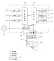
- Front view showing the processing device with the body cover removed Block diagram showing electrical configuration of processing equipment
- Block diagram showing electrical configuration of processing equipment The perspective view which shows the 1st cartridge by 3rd Embodiment. Block diagram showing electrical configuration of processing equipment
- FIGS. 1 and 2 show a processing apparatus 10 of the present invention.
- the processing apparatus 10 processes the sheet-like object 91 held by the holding member 90 shown in FIG. Specifically, the processing apparatus 10 forms a processing mark by grinding or cutting the surface of the object 91. As a result, a desired pattern or pattern made of a processing mark is formed on the surface of the object 91.
- the holding member 90 is a resin flat plate having a pressure-sensitive adhesive layer (not shown) on the surface, and holds a paper or resin sheet-like object 91 on the pressure-sensitive adhesive layer.
- the processing apparatus 10 includes a main body cover 11, an apparatus main body 12, an X-axis movement mechanism 13, a Y-axis movement mechanism 14, a Z-axis movement mechanism (not shown), and a carriage 15, as shown in FIGS. Moreover, the processing apparatus 10 is provided with the 1st cartridge 30 as shown in FIG. Although the details will be described later, the first cartridge 30 has a first processing tool 31 and is detachably attached to the carriage 15. The first cartridge 30 is for forming a processing mark by grinding or cutting on the surface of the object 91.
- the main body cover 11 is formed in a rectangular box shape as a whole, and covers the entire outside of the apparatus main body 12, the X-axis movement mechanism 13, the Y-axis movement mechanism 14, the carriage 15, and the first cartridge 30.
- the longitudinal direction of the main body cover 11 is defined as the left-right direction of the processing apparatus 10, and the side provided with an opening 111 described later is defined as the front side of the processing apparatus 10.
- the left-right direction is defined as the X-axis direction
- the front-rear direction is defined as the Y-axis direction
- the up-down direction is defined as the Z-axis direction.
- An opening 111 is formed on the front surface of the main body cover 11.
- An opening (not shown) through which the holding member 90 can pass is also formed on the rear surface of the main body cover 11 facing the opening 111.
- a front cover 112 is rotatably provided on the main body cover 11. The front cover 112 rotates over a position where the opening 111 is opened and a position where the opening 111 is closed.
- the operation panel 113 is provided on the upper part of the main body cover 11.
- the operation panel 113 has an input display unit 114 composed of a liquid crystal display and a transparent touch panel, and a plurality of buttons 115. The user can check various settings and operating conditions by operating the operation panel 113.
- the apparatus body 12 has a base 121 and a receiving mechanism 122.
- the base 121 is formed in a rectangular frame shape and is provided at the bottom of the main body cover 11.
- the receiving mechanism 122 is formed in a substantially horizontal flat plate shape.
- a holding member 90 that holds the object 91 is placed on the receiving mechanism 122.
- the receiving mechanism 122 receives a pressing force applied to the object 91 and the holding member 90 by the lower end portion (a processing unit 312 described later) of the first cartridge 30 when processing the object 91.
- the X-axis moving mechanism 13 moves the carriage 15 in the left-right direction, that is, in the X-axis direction.
- the X-axis moving mechanism 13 includes a pair of upper and lower X-axis guide rails 131 and 132, an X-axis motor 133, an X-axis drive gear (not shown), an X-axis driven gear 135, a pair of pulleys 136 and 137, and a timing belt 138. It is composed of
- the pair of upper and lower X-axis guide rails 131 and 132 are provided horizontally in the vertical direction.
- the X-axis motor 133 is a stepping motor, for example.
- An X-axis drive gear is fixed to a rotation shaft (not shown) of the X-axis motor 133.
- the X-axis drive gear meshes with the X-axis driven gear 135.
- the left pulley 136 is provided below the X-axis driven gear 135.
- the left pulley 136 rotates integrally with the X-axis driven gear 135.
- the timing belt 138 is stretched between the left pulley 136 and the right pulley 137. Although not shown in detail, a part of the timing belt 138 is connected to the carriage 15.
- the Y-axis moving mechanism 14 moves the object 91 held by the holding member 90 in the front-rear direction, that is, the Y-axis direction.
- the Y-axis moving mechanism 14 includes a driving roller 141, a pinch roller 142, a Y-axis motor 143, a Y-axis driving gear 144, and a Y-axis driven gear 145.
- the driving roller 141 and the pinch roller 142 are provided in parallel with the X-axis guide rails 131 and 132 so that the center of the shaft is in the left-right direction, that is, the X-axis direction.
- the holding member 90 disposed between the driving roller 141 and the pinch roller 142 is pressed against the driving roller 141 by the pinch roller 142.
- the Y-axis motor 143 is, for example, a stepping motor.
- a Y-axis drive gear 144 is fixed to a rotation shaft (not shown) of the Y-axis motor 143.
- the Y-axis driven gear 145 is fixed to the right end portion of the drive roller 141.
- the Y-axis drive gear 144 meshes with the Y-axis driven gear 145.
- the carriage 15 has a mounting portion 151 and a Z-axis moving mechanism (not shown).
- the mounting portion 151 is provided on the front side of the carriage 15 and detachably mounts and holds the first cartridge 30.
- the first cartridge 30 is mounted on the mounting portion 151 with the processing portion 312 of the first processing tool 31 exposed as shown in FIGS. 2 and 5.
- a Z axis moving mechanism (not shown) is provided inside the carriage 15 and moves the mounting portion 151 together with the first cartridge 30 in the vertical direction, that is, in the Z axis direction.
- the processing portion 312 of the first processing tool 31 attached to the first cartridge 30 is held by the sheet-like holding member 90. Contact the surface of the object 91.
- the processing unit 312 is pressing the surface of the object 91 with a predetermined pressing force.
- the processing apparatus 10 moves the carriage 15 in the X-axis direction by the X-axis moving mechanism 13 in a state where the processing unit 312 of the first processing tool 31 is in contact with the target 91, and the target by the Y-axis moving mechanism 14. 91 is moved in the Y-axis direction.
- the processing apparatus 10 forms the processing trace by grinding or cutting the surface of the object 91. That is, on the surface of the object 91, a desired pattern or pattern made of a processing mark is formed.
- the depth of the processing mark formed on the surface of the object 91 is, for example, about 0.01 mm to 0.03 mm. However, it is not limited to this value.
- the depth of the processing mark changes depending on the type of the object 91 and the pressing force by which the processing unit 312 presses the surface of the object 91, the pressing force is appropriately changed according to the type of the object 91. Is preferred.
- the processing apparatus 10 includes a control circuit 17, a moving mechanism drive circuit 18 (hereinafter referred to as a first drive circuit 18), a power supply circuit 19, and a connected portion 20.
- the control circuit 17 includes a central processing unit (CPU) and controls the entire processing apparatus 10.
- the control circuit 17 functions as a control unit that controls driving of the X-axis moving mechanism 13, the Y-axis moving mechanism 14, and the Z-axis moving mechanism.
- the control circuit 17 is connected to the input display unit 114 and buttons 115 of the operation panel 113, the RAM 171, the ROM 172, the first drive circuit 18, and the power supply circuit 19.
- the RAM 171 stores processing data for processing the object 91 by driving the motors 133, 143, and 152.
- the ROM 172 stores a drive control program for driving and controlling the motors 133, 143, and 152 based on the machining data stored in the RAM 171.
- the first drive circuit 18 drives the X-axis motor 133, the Y-axis motor 143, and the Z-axis motor 152 based on instructions from the control circuit 17, respectively.
- the power supply circuit 19 is connected to an external power supply 101 such as a commercial power supply (AC power supply).
- the power supply circuit 19 is connected to the control circuit 17, the first drive circuit 18, and a second drive circuit 36 described later.
- the power supply circuit 19 supplies power supplied from the external power supply 101 to the control circuit 17, the first drive circuit 18, and the second drive circuit 36.
- the power supply circuit 19 is controlled by the control circuit 17.
- the connected portion 20 is a female connector, for example, and is provided upward on the front side of the carriage 15.
- the connected portion 20 is electrically connected to the control circuit 17 and the power supply circuit 19.
- the connected portion 20 is provided at a position to be connected to the connecting portion 35 of the first cartridge 30 when the first cartridge 30 is attached to the attaching portion 151.
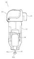
- the first cartridge 30 includes a first processing tool 31, an actuator 34, a first housing 32, a knob 33, a connecting portion 35, and a drive circuit 36 for the actuator shown in FIG. (Hereinafter referred to as the second drive circuit 36).
- the first processing tool 31 includes a columnar shaft portion 311 extending in the vertical direction, and a processing portion 312 provided at a tip portion, that is, a lower end portion of the shaft portion 311.
- the processing unit 312 is a conical grindstone that tapers downward. In this case, the first processing tool 31 can form a processing mark by grinding the surface of the object 91.
- the processing unit 312 may be a so-called end mill in which a blade is provided at the tip of a cylindrical shaft portion. In this case, the first processing tool 31 can cut the surface of the object 91 to form a processing mark.
- the shaft portion 311 of the first processing tool 31 is attached to the actuator 34.
- the actuator 34 is operated by an external power source or an internal power source of the first cartridge 30 to drive the first processing tool 31.
- the internal power supply will be described later.
- the actuator 34 is a motor, and the electric power from the external power supply 101 is supplied through the power supply circuit 19 and the second drive circuit 36 and operates to rotate the first processing tool 31.
- the processing unit 312 may be integrally provided at the tip of the rotation shaft of the actuator 34.
- the actuator 34 is not limited to a motor, and may be, for example, an ultrasonic vibrator. In this case, the actuator 34 can drive the first processing tool 31 by vibration.
- the first housing 32 constitutes the main body of the first cartridge 30.
- the first housing 32 is made of, for example, resin and is formed in a cylindrical shape that is long in the vertical direction as a whole, and has a space inside.
- the actuator 34 and the base end portion of the first processing tool 31, that is, a part of the shaft portion 311 are housed in the first housing 32. That is, the first housing 32 accommodates the first processing tool 31 and the actuator 34 in a state where the processing unit 312 that is the tip of the first processing tool 31 is exposed.
- the knob 33 is made of resin, for example, and is provided at the upper end of the first housing 32. The user can handle the first cartridge 30 by picking the knob 33.
- the connection unit 35 is for electrically connecting the control circuit 17 and the power supply circuit 19 to the second drive circuit 36.
- the connecting portion 35 is a male connector corresponding to the female connector that is the connected portion 20, and is provided downward on the upper rear side of the first housing 32, in this case, on the rear side of the knob portion 33. Yes.
- the connection part 35 is configured to be able to fit into the connected part 20.
- the connecting portion 35 is electrically connected to the actuator 34 via the second drive circuit 36.
- the connecting portion 35 and the second drive circuit 36, and the second drive circuit 36 and the actuator 34 are connected by lead wires, respectively, but in FIG. 7, the second drive circuit 36 and the lead wires are illustrated. Omitted.
- the connected portion 20 and the connecting portion 35 are not limited to the connector having the illustrated shape, and the control circuit 17 and the power supply circuit 19 on the apparatus main body 12 side and the second drive circuit 36 on the first cartridge 30 side are electrically connected. Any device that can be connected to the network is acceptable.
- the connecting portion 35 and the connected portion 20 When the connecting portion 35 and the connected portion 20 are connected, power from the external power supply 101 is supplied to the actuator 34 via the power supply circuit 19 on the apparatus main body 12 side and the second drive circuit 36 on the first cartridge 30 side. Is done. Further, when the connection unit 35 and the connected unit 20 are connected, the control circuit 17 outputs an operation command for the actuator 34 to the second drive circuit 36. As a result, the second drive circuit 36 operates the actuator 34 in response to an operation command from the control circuit 17 on the apparatus main body 12 side.
- the control circuit 17 controls the power supply circuit 19. That is, the control circuit 17 controls the power supplied from the external power source 101 to the actuator 34. Thereby, the rotation speed (rotation speed) of the actuator 34 (in this case, a motor) is controlled.
- the second drive circuit 36 may control the rotation speed (rotation speed) of the actuator 34 (in this case, the motor) based on the operation command from the control circuit 17. In this way, the control circuit 17 can control the start and stop of the operation of the actuator 34 and the rotation speed (rotation speed) thereof.
- the second drive circuit 36 is a switching relay, for example, and switches between energization and de-energization of power supplied from the external power supply 101 to the actuator 34 based on an operation command from the control circuit 17. Good.
- the user mounts the first cartridge 30 on the mounting portion 151 of the carriage 15. Then, as the first cartridge 30 is mounted, the connection part 35 on the first cartridge 30 side is connected to the connected part 20 on the apparatus main body 12 side. Thereby, the first cartridge 30 and the apparatus main body 12 are electrically connected, and the actuator 34 of the first cartridge 30 can be operated.
- the control circuit 17 can detect that the connecting portion 35 of the first cartridge 30 is connected to the connected portion 20.
- the control circuit 17 measures the potential between the power supply circuit 19 and the connected portion 20, and detects that the connecting portion 35 is connected to the connected portion 20 when the potential changes.
- the apparatus main body 12 may be configured to include a sensor that detects that the connected portion 20 and the connecting portion 35 are connected.
- control circuit 17 When the control circuit 17 executes the processing program, the control circuit 17 operates the actuator 34 to rotate the first processing tool 31. Then, the control circuit 17 drives the X-axis moving mechanism 13, the Y-axis moving mechanism 14, and the Z-axis moving mechanism on the basis of the processing data while the first processing tool 31 is rotated, so that the first processing tool 31 is rotated.
- the carriage 15 and the object 91 are relatively moved while the processing portion 312 of the tool 31 is in contact with the surface of the object 91. Thereby, a processing mark by grinding is formed on the surface of the object 91, and a desired pattern or design is formed on the surface of the object 91 by the processing mark.
- the processing apparatus 10 further includes a second cartridge 40 shown in FIG. 8 and a third cartridge 50 shown in FIG.
- the second cartridge 40 is for cutting the object 91 into a desired shape.
- the third cartridge 50 is for drawing a desired pattern or pattern on the surface of the object 91.
- the second cartridge 40 has a second processing tool 41, a second housing 42, a knob 43, and a cap 44.
- the second processing tool 41 is, for example, a cutter, and integrally includes a shaft portion 411 extending in the vertical direction and a blade portion 412 formed at the tip portion (lower end portion) of the shaft portion 411.
- the 2nd processing tool 41 is not restricted to this structure, For example, the structure which made the flat blade part adhere to the front-end
- the second housing 42 constitutes the main body of the second cartridge 40.
- the second housing 42 is made of, for example, a resin and is formed in a cylindrical shape that is long in the vertical direction as a whole, and accommodates the shaft portion 411 of the second processing tool 41 therein. have.
- the proximal end portion, that is, the shaft portion 411 of the second processing tool 41 is accommodated in the second housing 42. That is, the second housing 42 accommodates the second processing tool 41 in a state where the blade portion 412 that is the tip of the second processing tool 41 is exposed.
- the knob 43 has the same configuration as the knob 33 of the first cartridge 30.
- the cap 44 is provided so as to be rotatably screwed to the lower portion of the second housing 42. Although a detailed description is omitted, the protrusion amount of the blade portion 412 can be changed by rotating the cap 44.
- the third cartridge 50 includes a pen 51, a third housing 52, a knob 53, and a cap 54.
- the pen 51 is configured in a rod shape that is long in the vertical direction, for example.
- the third casing 52, the knob 53, and the cap 54 of the third cartridge 50 have the same configuration as the second casing 42, the knob 43, and the cap 44 of the second cartridge 40. That is, the third housing 52 accommodates the pen 51 in a state where the tip end portion of the pen 51 is exposed.
- the second cartridge 40 and the third cartridge 50 can be mounted on the mounting portion 151 of the carriage 15. That is, the mounting portion 151 can alternatively mount the first cartridge 30, the second cartridge 40, and the third cartridge 50.
- the second cartridge 40 and the third cartridge 50 do not have a configuration corresponding to the connection portion 35 of the first cartridge 30.
- the second cartridge 40 and the third cartridge 50 may have a configuration similar to the dummy connection portion, that is, the connection portion 35. In this case, for example, it occurs on the output side of the power supply circuit 19 when the dummy connecting portion is connected to the connected portion 20 and when the connecting portion 35 of the first cartridge 30 is connected to the connected portion 20. Try to make the potential difference different. Accordingly, the control circuit 17 detects that any of the first cartridge 30, the second cartridge 40, or the third cartridge 50 is mounted on the mounting portion 151.
- control circuit 17 When the control circuit 17 detects that the first cartridge 30 is mounted on the mounting portion 151, the control circuit 17 causes the first processing tool 31 to form a processing mark by grinding on the surface of the object 91. Control the drive of the moving mechanism. In addition, when the control circuit 17 detects that the second cartridge 40 is mounted on the mounting portion 151, the control circuit 17 controls the driving of each moving mechanism so that the object 91 is cut by the second processing tool 41. . Further, when the control circuit 17 detects that the third cartridge 50 is mounted on the mounting portion 151, the control circuit 17 drives each moving mechanism so as to draw a pattern or the like on the surface of the object 91 with the pen 51. Control.
- the processing apparatus 10 can perform processing other than cutting and drawing on the object 91, that is, processing for forming a pattern or a pattern by a processing mark by grinding.
- processing other than cutting and drawing can be performed on the object 91.
- the range of user processing options is widened, and convenience is improved.
- the processing apparatus 10 performs processing for forming a pattern or a pattern on the object 91 by processing marks by cutting. Can be applied.
- connection part 35 on the first cartridge 30 side When the connection part 35 on the first cartridge 30 side is connected to the connected part 20 on the apparatus main body 12 side, the power from the external power supply 101 is supplied from the power supply circuit 19 on the apparatus main body 12 side and the first cartridge 30 side. 2 is supplied to the actuator 34 via the drive circuit 36. According to this, it is not necessary to provide the first cartridge 30 with a power source for operating the actuator 34. Therefore, the number of parts constituting the first cartridge 30 can be reduced, and as a result, the weight and size of the first cartridge 30 can be reduced, and the part cost can be reduced.
- the control circuit 17 can control the power supplied from the external power supply 101 to the actuator 34 by controlling the power supply circuit 19. That is, the control circuit 17 controls the movement of each moving mechanism and the operation and rotation speed (rotational speed) of the actuator 34. Therefore, the control circuit 17 can perform machining control suitable for the type of the object 91 based on the machining data.
- the connected portion 20 on the apparatus body 12 side is provided at a position where the first cartridge 30 is connected to the connecting portion 35 when the first cartridge 30 is attached to the mounting portion 151.
- the connecting portion 35 on the first cartridge 30 side is inevitably connected to the connected portion 20 on the apparatus main body 12 side.
- the control circuit 17 and the power supply circuit 19 on the apparatus main body 12 side and the second drive circuit 36 on the first cartridge 30 side are electrically connected.
- the user attaches the first cartridge 30 to the attachment portion 151 in order to connect the control circuit 17 and the power supply circuit 19 on the apparatus main body 12 side and the second drive circuit 36 on the first cartridge 30 side. There is no need to do other work. Accordingly, it is possible to save the user's trouble and to suppress forgetting or mistaken connection between the control circuit 17 and the power supply circuit 19 on the apparatus main body 12 side and the second drive circuit 36 on the first cartridge 30 side. .
- the processing apparatus 10 includes a second cartridge 40 having a second processing tool 41 and a third cartridge 50 having a pen 51 in addition to the first cartridge 30 having the first processing tool 31.
- the mounting portion 151 can alternatively mount the first cartridge 30, the second cartridge 40, or the third cartridge 50. According to this, in addition to the formation of the processing trace by the first processing tool 31, the processing apparatus 10 can also perform the cutting by the second processing tool 41 and the drawing by the pen 51. Therefore, the range of selection of processing by the user is widened, and the convenience is further improved.
- the processing apparatus 10 includes a transmission circuit 21 and a first cartridge 60.
- the transmission circuit 21 is provided on the apparatus body 12 side and is connected to the control circuit 17.
- the transmission circuit 21 transmits an operation command from the control circuit 17 to the first cartridge 60 by wireless communication, and functions as a transmission unit.
- the first cartridge 60 is configured to receive an operation command by wireless communication from the control circuit 17 and operate the actuator 34 by an internal power source.
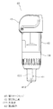
- the first cartridge 60 in the second embodiment includes a first processing tool 31, a knob 33, an actuator 34, a second drive circuit 36, a first housing 61, a battery 62, and a receiving circuit 63. is doing.
- the first casing 61 is configured to be longer in the vertical direction than the first casing 32 of the first embodiment.
- the battery 62 is housed in the first housing 61 and is, for example, a primary battery that is a normal dry battery, but may be a secondary battery such as a rechargeable battery.
- the battery 62 supplies power to the actuator 34 via the second drive circuit 36. That is, the battery 62 is an internal power source for operating the actuator 34.
- the receiving circuit 63 is accommodated in the first housing 61 as shown in FIG. As shown in FIG. 11, the receiving circuit 63 is electrically connected to the second drive circuit 36, receives the operation command transmitted from the transmission circuit 21, and sends the operation command to the second drive circuit 36. Tell. In this case, the reception circuit 63 functions as a reception unit that receives the operation command transmitted from the transmission circuit 21.
- the processing apparatus 10 does not include the connected portion 20 and the connecting portion 35. That is, the connected portion 20 on the apparatus main body 12 side and the connecting portion 35 on the first cartridge 60 side are not provided.
- the processing apparatus 10 is configured to be able to determine the type of cartridge mounted on the mounting portion 151.
- the transmission circuit 21 and the reception circuit 63 may be configured to perform so-called short-range wireless communication that enables the transmission circuit 21 and the reception circuit 63 to communicate with each other in a state where the first cartridge 60 is mounted on the mounting portion 151. Good.
- the control circuit 17 detects that the first cartridge 60 is mounted on the mounting portion 151 by detecting a state in which the receiving circuit 63 and the transmitting circuit 21 can perform wireless communication.
- the control circuit 17 transmits an operation command for the actuator 34 from the transmission circuit 21.
- the reception circuit 63 transmits the operation command to the second drive circuit 36, and the second drive circuit 36 operates the actuator 34.
- the connector it is not necessary to electrically connect the first cartridge 60 and the apparatus main body 12 by the connector. That is, the number of parts and the part cost can be reduced by the amount that the connector is unnecessary. In addition, the user can easily handle the first cartridge 60 and the convenience is further improved.
- the first cartridge 70 of the third embodiment is also configured to operate the actuator 34 with the internal power supply without receiving power supply from the external power supply 101 via the apparatus main body 12.
- the actuator 34 according to the third embodiment is configured to operate independently of the control of the control circuit 17 without receiving a wired or wireless operation command from the control circuit 17. That is, the first cartridge 70 of the third embodiment has a completely independent configuration with respect to the apparatus main body 12.
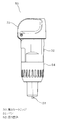
- the first cartridge 70 in the third embodiment includes a first processing tool 31, a knob 33, an actuator 34, a first housing 61, a battery 62, and a switch 71.
- the switch 71 is provided on the side surface of the first housing 61 as shown in FIG.
- the switch 71 switches between energization and de-energization of power supplied from the battery 62 to the actuator 34. That is, when the switch 71 is on, power is supplied from the battery 62 to the actuator 34, and the actuator 34 operates. On the other hand, when the switch 71 is off, the power from the battery 62 to the actuator 34 is cut off, and the actuator 34 stops. Thus, the user can operate or stop the actuator 34 by turning the switch 71 on and off.
- the apparatus main body 12 of the third embodiment does not include the connected portion 20 of the first embodiment and the transmission circuit 21 of the second embodiment.
- the first cartridge 70 of the third embodiment does not include the connection unit 35 of the first embodiment and the receiving circuit 63 of the second embodiment.
- the processing apparatus 10 of the third embodiment includes the first cartridge without including the connected portion 20 and the connecting portion 35 of the first embodiment, or the transmission circuit 21 and the receiving circuit 63 of the second embodiment.
- 70 can be used. That is, for example, even in a conventional cutting device including a cutter cartridge and a pen cartridge, by attaching the first cartridge 70, the object is processed to form a pattern or a pattern by processing marks by grinding. Will be able to.
- the present invention is not limited to the above-described embodiments, and various expansions and modifications can be made without departing from the gist thereof.
- the electrical configurations of the processing apparatus 10 and the first cartridges 30 and 60 can be changed as appropriate.
- the type of motor that is an actuator accommodated in the first cartridge 30, 60, and 70 and the control method thereof can be appropriately changed.
- the shape of the process part 312 of the 1st processing tool 31 is not limited to cone shape, For example, a disk shape, a column shape, a prism shape, or a hemisphere may be sufficient.
- the first cartridge 70 may have a drive circuit for operating the actuator 34.
- the configurations of the above embodiments can be combined as appropriate.
- Processing device 13 X-axis moving mechanism (moving mechanism) 14 Y-axis moving mechanism (moving mechanism) 15 Carriage 151 Mounting part 17 Control circuit (control part) 20 connected part 21 transmitting circuit (transmitting part) 30 First Cartridge 31 First Processing Tool 32 First Housing 34 Actuator 35 Connection 40 Second Cartridge 41 Second Processing Tool 42 Second Housing 50 Third Cartridge 51 Pen 52 Third Housing 60 First Cartridge 61 First 1 case 62 battery (internal power supply) 63 Receiver circuit (receiver) 70 First cartridge 71 Switch 91 Object 101 External power supply
Landscapes
- Engineering & Computer Science (AREA)
- Mechanical Engineering (AREA)
- Life Sciences & Earth Sciences (AREA)
- Forests & Forestry (AREA)
- General Engineering & Computer Science (AREA)
- Control Of Cutting Processes (AREA)
- Milling Processes (AREA)
Abstract
切断及び描画以外の加工も施すことができる加工装置及びその加工装置に用いられるカートリッジを提供する。加工装置は、シート状の対象物の表面を研削又は切削して加工痕を形成する第1加工具31と、外部電源101により動作して、第1加工具31を駆動するアクチュエータ34と、第1加工具31の先端部を露出させた状態で第1加工具31を収容するとともに、アクチュエータ34を収容する第1筐体と、を有する第1カートリッジ30を備える。また、加工装置は、第1カートリッジ30を着脱可能に装着する装着部を有するキャリッジと、対象物とキャリッジとを相対的に移動させる移動機構と、第1加工具31で対象物の表面に加工痕を形成するように移動機構の駆動を制御する制御回路17と、を備える。
Description
本発明は、加工具を有するカートリッジを用いて対象物の表面に加工を施す加工装置、及びその加工装置に用いられるカートリッジに関する。
従来、紙などのシート状の対象物を所望の形状に切断する切断装置が公知である(例えば、引用文献1を参照)。前記切断装置は、対象物を切断するカッタカートリッジ以外に、ペンが内蔵されたペンカートリッジと、これらのカートリッジを択一的に装着可能なキャリッジを備える。これより、当該切断装置は、ペンカートリッジをキャリッジに装着して、対象物の表面に所望の模様や図柄を描画することもできる。
しかしながら、前記切断装置において、対象物に対して切断や描画以外の加工を施したいとの要望がある。例えば、対象物の表面を研削又は切削して加工痕を形成する加工である。
本発明の目的は、対象物の表面を研削又は切削して加工痕を形成する加工を施すことができる加工装置、及びその加工装置に用いられるカートリッジを提供する。
上記の目的を達成するために、本発明の請求項1に係る加工装置は、シート状の対象物の表面を研削又は切削して加工痕を形成する第1加工具と、外部又は内部電源により動作して、前記第1加工具を駆動するアクチュエータと、前記第1加工具の先端部を露出させた状態で前記第1加工具を収容するとともに、前記アクチュエータを収容する第1筐体と、を有する第1カートリッジと、前記第1カートリッジを着脱可能に装着する装着部を有するキャリッジと、前記対象物と前記キャリッジとを相対的に移動させる移動機構と、前記第1加工具で前記対象物の表面に加工痕を形成するように前記移動機構の駆動を制御する制御部と、を備えることを特徴とする。
本発明の請求項10に係るカートリッジは、シート状の対象物の表面を研削又は切削して加工痕を形成する第1加工具と、外部又は内部電源により動作して、前記第1加工具を駆動するアクチュエータと、前記第1加工具の先端部を露出させた状態で前記第1加工具を収容するとともに、前記アクチュエータを収容する筐体と、を備える。カートリッジは、加工装置が有するキャリッジの装着部に着脱可能に装着されて、前記アクチュエータが動作された状態で前記対象物と前記キャリッジとが相対的に移動されることで、前記第1加工具が前記対象物の表面に加工痕を形成することを特徴とする。
請求項1の加工装置によれば、対象物に対して、切断や描画以外の加工、つまり研削又は切削による加工痕によって模様や図柄を形成する加工を施すことができる。また、当該加工装置に、第1カートリッジではなく切断又は描画加工を施す為のカートリッジを装着すれば、従来の装置と同様に、対象物の切断加工又は対象物の表面への描画加工を施すことができる。
また、請求項10のカートリッジによれば、当該カートリッジを加工装置のキャリッジに装着してアクチュエータを動作させ、対象物とキャリッジをと相対的に移動させることで、対象物に対して、研削又は切削による加工痕によって模様や図柄を形成する加工を施すことができる。
以下、本発明の複数の実施形態による加工装置及びカートリッジについて、図面を参照して説明する。
(第1実施形態)
まず、第1実施形態について、図1から図9を参照して説明する。
図1及び図2は、本発明の加工装置10を示している。加工装置10は、図1に示す保持部材90に保持されたシート状の対象物91に対して加工を施すものである。具体的には、加工装置10は、対象物91の表面を研削又は切削して加工痕を形成する。これにより、対象物91の表面には、加工痕からなる所望の模様や図柄が形成される。
まず、第1実施形態について、図1から図9を参照して説明する。
図1及び図2は、本発明の加工装置10を示している。加工装置10は、図1に示す保持部材90に保持されたシート状の対象物91に対して加工を施すものである。具体的には、加工装置10は、対象物91の表面を研削又は切削して加工痕を形成する。これにより、対象物91の表面には、加工痕からなる所望の模様や図柄が形成される。
保持部材90は、表面に粘着層(図示せず)を有する樹脂製の平板であり、紙や樹脂のシート状の対象物91を粘着層に貼り付けて保持する。加工装置10は、図1及び図2に示すように、本体カバー11、装置本体12、X軸移動機構13、Y軸移動機構14、図示しないZ軸移動機構、及びキャリッジ15を備えている。また、加工装置10は、図2に示すように、第1カートリッジ30を備えている。第1カートリッジ30は、詳細は後述するが、第1加工具31を有し、キャリッジ15に着脱可能に取り付けられる。第1カートリッジ30は、対象物91の表面に、研削又は切削による加工痕を形成するためのものである。
本体カバー11は、全体として矩形の箱状に構成されており、装置本体12、X軸移動機構13、Y軸移動機構14、キャリッジ15、及び第1カートリッジ30の外側全体を覆っている。以下の説明において、本体カバー11の長手方向を加工装置10の左右方向とし、後述する開口部111が設けられる側を加工装置10の前側とする。また、加工装置10に対し、左右方向をX軸方向、前後方向をY軸方向、上下方向をZ軸方向と定義する。
本体カバー11の正面には、開口部111が形成されている。本体カバー11の開口部111に対向する後面にも、保持部材90が通過可能な開口部(図示せず)が形成されている。本体カバー11には、前カバー112が回動可能に設けられている。前カバー112は、開口部111を開放する位置と開口部111を閉じる位置とに亘って回動する。操作パネル113は、本体カバー11の上部に設けられている。操作パネル113は、液晶ディスプレイと透明タッチパネルで構成された入力表示部114と、複数のボタン115を有している。ユーザは、操作パネル113を操作することによって、各種の設定や動作状況の確認を行うことができる。
装置本体12は、基台121、及び受け機構122を有している。基台121は、矩形の枠状に形成され、本体カバー11の底部に設けられている。受け機構122は、略水平な平板状に形成されている。受け機構122には、対象物91を保持した保持部材90が載置される。受け機構122は、対象物91に対して加工を施す際に、第1カートリッジ30の下端部(後述の加工部312)が、対象物91及び保持部材90に与える押圧力を受ける。
X軸移動機構13は、キャリッジ15を左右方向つまりX軸方向へ移動させる。X軸移動機構13は、上下一対のX軸ガイドレール131、132、X軸モータ133、X軸駆動ギヤ(図示せず)、X軸従動ギヤ135、一対のプーリ136、137、及びタイミングベルト138から構成されている。
上下一対のX軸ガイドレール131、132は、上下に水平に並んで設けられている。X軸モータ133は、例えばステッピングモータである。X軸モータ133の回転軸(図示せず)には、X軸駆動ギヤが固定されている。X軸駆動ギヤは、X軸従動ギヤ135と噛み合う。
左右一対のプーリ136、137のうち、左側プーリ136は、X軸従動ギヤ135の下側に設けられている。左側プーリ136は、X軸従動ギヤ135と一体的に回転する。タイミングベルト138は、左側プーリ136と右側プーリ137との間に亘って架けられている。詳しくは図示しないが、タイミングベルト138の一部が、キャリッジ15に接続されている。
この構成において、X軸モータ133の回転軸が回転すると、これに伴いX軸駆動ギヤ、X軸従動ギヤ135、及び左側プーリ136が回転する。左側プーリ136が回転することによって、タイミングベルト138が移動する。これによりキャリッジ15は、タイミングベルト138の移動に伴って左右方向つまりX軸方向へ移動する。
Y軸移動機構14は、保持部材90に保持された対象物91を前後方向つまりY軸方向へ移動させる。Y軸移動機構14は、駆動ローラ141、ピンチローラ142、Y軸モータ143、Y軸駆動ギヤ144、及びY軸従動ギヤ145から構成されている。駆動ローラ141及びピンチローラ142は、軸中心が左右方向すなわちX軸方向へ向くようにX軸ガイドレール131、132と平行に設けられている。駆動ローラ141とピンチローラ142との間に配置された保持部材90は、ピンチローラ142によって駆動ローラ141に押し付けられる。
Y軸モータ143は、例えばステッピングモータである。Y軸モータ143の回転軸(図示せず)には、Y軸駆動ギヤ144が固定されている。Y軸従動ギヤ145は、駆動ローラ141の右端部に固定されている。Y軸駆動ギヤ144は、Y軸従動ギヤ145と噛み合っている。
この構成において、Y軸モータ143の回転軸が回転すると、これに伴いY軸駆動ギヤ144、Y軸従動ギヤ145、及び駆動ローラ141が回転する。そして、駆動ローラ141が回転することにより、駆動ローラ141とピンチローラ142との間に挟持された保持部材90は、前後方向つまりY軸方向へ移動する。このように、X軸移動機構13及びY軸移動機構14は、対象物91とキャリッジ15とを相対的に移動させる。
キャリッジ15は、装着部151と図示しないZ軸移動機構とを有している。装着部151は、キャリッジ15の前側に設けられ、第1カートリッジ30を着脱可能に装着し保持する。第1カートリッジ30は、図2、図5に示すように第1加工具31の加工部312を露出させた状態で、装着部151に装着される。図示しないZ軸移動機構は、キャリッジ15の内部に設けられており、装着部151を第1カートリッジ30とともに上下方向つまりZ軸方向へ移動させる。
この構成において、Z軸移動機構によって装着部151が下方へ移動されると、第1カートリッジ30に取り付けられた第1加工具31の加工部312は、シート状の保持部材90に保持されている対象物91の表面に接触する。このとき、詳しくは、加工部312が、対象物91の表面を所定の押圧力で押圧している状態となっている。加工装置10は、第1加工具31の加工部312を対象物91に接触させた状態で、X軸移動機構13によってキャリッジ15をX軸方向へ移動させるとともに、Y軸移動機構14によって対象物91をY軸方向へ移動させる。これにより、加工装置10は、対象物91の表面を研削又は切削加工して加工痕を形成する。つまり、対象物91の表面には、加工痕からなる所望の模様や図柄が形成される。
ここで、対象物91の表面に形成される加工痕の深さは、例えば、0.01mm~0.03mm程度である。但し、この数値に限定されるものではない。なお、加工痕の深さは、対象物91の種類、及び加工部312が対象物91の表面を押圧する押圧力により変化するので、対象物91の種類に応じて押圧力を適宜変更することが好ましい。
次に、加工装置10の電気的構成を説明する。加工装置10は、図3に示すように、制御回路17、移動機構用の駆動回路18(以下、第1駆動回路18と称する)、電源回路19、及び被接続部20を備えている。制御回路17は、中央演算処理装置(CPU)を含み、加工装置10の全体の制御を司っている。この場合、制御回路17は、X軸移動機構13、Y軸移動機構14、及びZ軸移動機構の駆動を制御する制御部として機能する。制御回路17には、操作パネル113の入力表示部114及びボタン115、RAM171、ROM172、第1駆動回路18、並びに電源回路19が接続されている。
RAM171は、各モータ133、143、152を駆動させて対象物91に加工を行うための加工データなどを記憶する。ROM172は、RAM171に記憶された加工データに基づいて各モータ133、143、152を駆動制御するための駆動制御プログラムなどを記憶する。第1駆動回路18は、制御回路17からの命令に基づいて、X軸モータ133、Y軸モータ143、Z軸モータ152を夫々駆動させる。電源回路19は、例えば商用電源(AC電源)などの外部電源101に接続される。電源回路19は、制御回路17、第1駆動回路18、及び後述する第2駆動回路36に接続される。電源回路19は、外部電源101から供給される電力を、制御回路17、第1駆動回路18、及び第2駆動回路36に供給する。電源回路19は、制御回路17によって制御される。
被接続部20は、図4に示すように、例えば雌型コネクタであって、キャリッジ15の前面側において上方へ向けて設けられている。被接続部20は、制御回路17及び電源回路19に電気的に接続されている。被接続部20は、図4から図6に示すように、第1カートリッジ30が装着部151に装着されたときに、第1カートリッジ30の接続部35に接続される位置に設けられている。
次に、第1カートリッジ30の構成を説明する。第1カートリッジ30は、図6及び図7に示すように、第1加工具31、アクチュエータ34、第1筐体32、摘み部33、接続部35、及び図3に示すアクチュエータ用の駆動回路36(以下、第2駆動回路36と称する)を有している。第1加工具31は、上下方向へ延びる円柱状の軸部311と、この軸部311の先端部つまり下端部に設けられた加工部312と、を有している。加工部312は、下方へ向かって先細る円錐状の砥石である。この場合、第1加工具31は、対象物91の表面を研削して加工痕を形成することができる。また、加工部312は、図示しないが、円柱状の軸部の先端に刃を設けたいわゆるエンドミルでもよい。この場合、第1加工具31は、対象物91の表面を切削して加工痕を形成することができる。
第1加工具31の軸部311は、アクチュエータ34に取り付けられている。アクチュエータ34は、第1カートリッジ30の外部電源又は内部電源により動作して、第1加工具31を駆動するものである。内部電源については後述する。本実施形態の場合、アクチュエータ34はモータであり、外部電源101からの電力が電源回路19及び第2駆動回路36を介して供給されて動作し、第1加工具31を回転させる。なお、アクチュエータ34の回転軸の先端に、加工部312を一体的に設ける構成にしてもよい。また、アクチュエータ34は、モータに限られず、例えば超音波振動子であってもよい。この場合、アクチュエータ34は、第1加工具31を振動により駆動させることができる。
第1筐体32は、第1カートリッジ30の本体を構成するものである。第1筐体32は、例えば樹脂製であって、全体として上下方向へ長い円筒状に形成され、内部に空間を有している。アクチュエータ34、及び第1加工具31の基端部つまり軸部311の一部は、第1筐体32の内部に収容されている。すなわち、第1筐体32は、第1加工具31の先端部である加工部312を露出させた状態で第1加工具31を収容するとともに、アクチュエータ34を収容している。摘み部33は、例えば樹脂製であって、第1筐体32の上端部に設けられている。ユーザは、摘み部33を摘まんで第1カートリッジ30を取り扱うことができる。
接続部35は、制御回路17及び電源回路19と、第2駆動回路36を電気的に接続するためのものである。接続部35は、被接続部20である雌型コネクタに対応する雄型コネクタであって、第1筐体32の上部後側、この場合摘み部33の後側において下方へ向けて設けられている。接続部35は、被接続部20と嵌合可能に構成されている。接続部35は、図3に示すように、第2駆動回路36を介して、アクチュエータ34に電気的に接続されている。具体的には、接続部35と第2駆動回路36、第2駆動回路36とアクチュエータ34は、リード線で夫々接続されているが、図7では、第2駆動回路36及びリード線の図示は省略している。なお、被接続部20及び接続部35は、図示した形状のコネクタに限られず、装置本体12側の制御回路17及び電源回路19と、第1カートリッジ30側の第2駆動回路36とを電気的に接続できるものであればよい。
接続部35と被接続部20とが接続された場合、外部電源101からの電力は、装置本体12側の電源回路19及び第1カートリッジ30側の第2駆動回路36を介してアクチュエータ34に供給される。また、接続部35と被接続部20とが接続された場合、制御回路17は、第2駆動回路36に対して、アクチュエータ34の動作指令を出力する。これにより、第2駆動回路36は、装置本体12側の制御回路17からの動作指令を受けて、アクチュエータ34を動作させる。
この場合、制御回路17は、電源回路19を制御する。すなわち、制御回路17は、外部電源101からアクチュエータ34に供給される電力を制御する。これより、アクチュエータ34(この場合、モータ)の回転数(回転速度)が制御される。なお、第2駆動回路36が、制御回路17からの動作指令に基づいて、アクチュエータ34(この場合、モータ)の回転数(回転速度)を制御してもよい。このように、制御回路17は、アクチュエータ34の動作の開始及び停止や、その回転数(回転速度)を制御することができる。また、第2駆動回路36は、例えばスイッチングリレーであって、制御回路17からの動作指令に基づいて、外部電源101からアクチュエータ34へ供給する電力の通電と非通電とを切り換えるものであってもよい。
対象物91の表面に研削による加工痕を形成する際、ユーザは、第1カートリッジ30を、キャリッジ15の装着部151に装着する。すると、第1カートリッジ30の装着に伴って、第1カートリッジ30側の接続部35が、装置本体12側の被接続部20と接続される。これにより、第1カートリッジ30と装置本体12とが電気的に接続されて、第1カートリッジ30のアクチュエータ34が動作可能になる。
制御回路17は、被接続部20に、第1カートリッジ30の接続部35が接続されたことを検出することができる。例えば、制御回路17は、電源回路19と被接続部20との間の電位を計測し、その電位に変化があった場合に、被接続部20に接続部35が接続されたことを検出する。また、装置本体12は、上記の構成とは異なり、被接続部20と接続部35とが接続されたことを検出するセンサを備えた構成であってもよい。
制御回路17は、加工用のプログラムを実行すると、アクチュエータ34を動作させて第1加工具31を回転させる。そして、制御回路17は、第1加工具31を回転させた状態で、加工データに基づいて、X軸移動機構13、Y軸移動機構14、及びZ軸移動機構を駆動させて、第1加工具31の加工部312を対象物91の表面に接触させながらキャリッジ15と対象物91とを相対的に移動させる。これにより、対象物91の表面には、研削による加工痕が形成されて、その加工痕により対象物91の表面に所望の模様や図柄が形成される。
また、加工装置10は、図8に示す第2カートリッジ40、及び図9に示す第3カートリッジ50を更に備えている。第2カートリッジ40は、対象物91を所望の形状に切断するためのものである。第3カートリッジ50は、対象物91の表面に所望の模様や図柄を描画するためのものである。
図8に示すように、第2カートリッジ40は、第2加工具41、第2筐体42、摘み部43、及びキャップ44を有している。第2加工具41は、例えばカッタであり、上下方向へ延びる軸部411と、軸部411の先端部(下端部)に形成された刃部412とを一体に有している。なお、第2加工具41はこの構成に限られず、例えば、軸部の先端に、平板状の刃部を固着させた構成でもよい。
第2筐体42は、第2カートリッジ40の本体を構成するものである。第2筐体42は、第1筐体32と同様に、例えば樹脂製であって、全体として上下方向へ長い円筒状に形成され、内部に第2加工具41の軸部411を収容する空間を有している。第2加工具41の基端部つまり軸部411は、第2筐体42の内部に収容されている。すなわち、第2筐体42は、第2加工具41の先端部である刃部412を露出させた状態で第2加工具41を収容している。摘み部43は、第1カートリッジ30の摘み部33と同様の構成である。また、キャップ44は、第2筐体42の下部に対して回転可能に螺合して設けられている。詳細な説明は省略するが、キャップ44を回転させることで、刃部412の突出量を変更することができる。
第3カートリッジ50は、ペン51、第3筐体52、摘み部53、及びキャップ54を有している。ペン51は、例えば上下方向へ長い棒状に構成されている。第3カートリッジ50の第3筐体52、摘み部53、及びキャップ54は、第2カートリッジ40の第2筐体42、摘み部43、及びキャップ44と同様の構成である。すなわち、第3筐体52は、ペン51の先端部を露出させた状態でペン51を収容している。第2カートリッジ40及び第3カートリッジ50は、キャリッジ15の装着部151に装着可能である。すなわち、装着部151は、第1カートリッジ30、第2カートリッジ40、及び第3カートリッジ50を択一的に装着することができる。
なお、本実施形態において、第2カートリッジ40及び第3カートリッジ50は、第1カートリッジ30の接続部35に相当する構成を有していない。しかし、第2カートリッジ40及び第3カートリッジ50は、ダミーの接続部つまり接続部35に類似する構成を有していてもよい。この場合、例えば、ダミーの接続部が被接続部20に接続された場合と、第1カートリッジ30の接続部35が被接続部20に接続された場合とで、電源回路19の出力側に生じる電位差を異ならせるようにする。これにより、制御回路17は、第1カートリッジ30、第2カートリッジ40、又は第3カートリッジ50の何れかが装着部151に装着されたことを検出する。
制御回路17は、装着部151に第1カートリッジ30が装着されたことを検出した場合には、第1加工具31で対象物91の表面に研削による加工痕を形成するように、前述した各移動機構の駆動を制御する。また、制御回路17は、装着部151に第2カートリッジ40が装着されたことを検出した場合には、第2加工具41で対象物91を切断するように、各移動機構の駆動を制御する。また、制御回路17は、装着部151に第3カートリッジ50が装着されたことを検出した場合には、ペン51で対象物91の表面に模様等を描画するように、各移動機構の駆動を制御する。
これによれば、加工装置10は、対象物91に対して、切断や描画以外の加工、つまり研削による加工痕によって模様や図柄を形成する加工を施すことができる。換言すれば、本実施形態の加工装置10及び第1カートリッジ30によれば、対象物91に対して切断及び描画以外の加工も施すことができる。その結果、ユーザの加工の選択の幅が広がり、利便性の向上が図られる。また、第1カートリッジ30の第1加工具31の加工部312が砥石ではなくエンドミルである場合、加工装置10は、対象物91に対して、切削による加工痕によって模様や図柄を形成する加工を施すことができる。
第1カートリッジ30側の接続部35が、装置本体12側の被接続部20に接続された場合、外部電源101からの電力は、装置本体12側の電源回路19及び第1カートリッジ30側の第2駆動回路36を介してアクチュエータ34に供給される。これによれば、アクチュエータ34を動作させるための電源を、第1カートリッジ30に設ける必要は無い。そのため、第1カートリッジ30を構成する部品点数を削減することができ、ひいては第1カートリッジ30の軽量化、小型化、及び部品コストの削減を図ることができる。
制御回路17は、電源回路19を制御することで、外部電源101からアクチュエータ34に供給される電力を制御することができる。すなわち、制御回路17は、各移動機構の移動、及びアクチュエータ34の動作及び回転数(回転速度)を制御する。したがって、制御回路17は、加工データに基づいて、対象物91の種類に適した加工制御を行うことができる。
装置本体12側の被接続部20は、第1カートリッジ30が装着部151に装着されたときに接続部35に接続される位置に設けられている。これによれば、第1カートリッジ30が装着部151に装着されると、第1カートリッジ30側の接続部35は、必然的に装置本体12側の被接続部20に接続される。すると、装置本体12側の制御回路17及び電源回路19と、第1カートリッジ30側の第2駆動回路36とが、電気的に接続される。この場合、ユーザは、装置本体12側の制御回路17及び電源回路19と、第1カートリッジ30側の第2駆動回路36とを接続するために、第1カートリッジ30を装着部151に装着する作業とは別の作業を行う必要がない。したがって、ユーザの手間を省くことができるとともに、装置本体12側の制御回路17及び電源回路19と、第1カートリッジ30側の第2駆動回路36との接続の忘れやミスを抑制することができる。
加工装置10は、第1加工具31を有する第1カートリッジ30に加えて、第2加工具41を有する第2カートリッジ40と、ペン51を有する第3カートリッジ50と、を備えている。装着部151は、第1カートリッジ30、第2カートリッジ40、又は第3カートリッジ50を択一的に装着可能である。これによれば、加工装置10は、第1加工具31による加工痕の形成に加えて、第2加工具41による切断、及びペン51による描画も行うことができる。したがって、ユーザの加工の選択の幅が広がり、更なる利便性の向上が図られる。
(第2実施形態)
次に、第2実施形態について、図10及び図11を参照して説明する。主に、第1実施形態とは異なる構成について説明する。
第2実施形態において、加工装置10は、送信回路21及び第1カートリッジ60を備えている。送信回路21は、装置本体12側に設けられて、制御回路17に接続されている。送信回路21は、第1カートリッジ60に対して、制御回路17からの動作指令を無線通信により送信するものであり、送信部として機能する。
次に、第2実施形態について、図10及び図11を参照して説明する。主に、第1実施形態とは異なる構成について説明する。
第2実施形態において、加工装置10は、送信回路21及び第1カートリッジ60を備えている。送信回路21は、装置本体12側に設けられて、制御回路17に接続されている。送信回路21は、第1カートリッジ60に対して、制御回路17からの動作指令を無線通信により送信するものであり、送信部として機能する。
第1カートリッジ60は、制御回路17からの無線通信による動作指令を受けるとともに、内部電源によってアクチュエータ34を動作させるように構成されている。具体的には、第2実施形態における第1カートリッジ60は、第1加工具31、摘み部33、アクチュエータ34、第2駆動回路36、第1筐体61、電池62、及び受信回路63を有している。
第1筐体61は、第1実施形態の第1筐体32よりも上下方向に長く構成されている。電池62は、図10に示すように、第1筐体61内に収容されており、例えば普通の乾電池である一次電池であるが、充電池などの二次電池であってもよい。電池62は、図11に示すように、第2駆動回路36を介してアクチュエータ34に電力を供給する。すなわち、電池62は、アクチュエータ34を動作させるための内部電源である。
受信回路63は、図10に示すように、第1筐体61内に収容されている。受信回路63は、図11に示すように、第2駆動回路36に電気的に接続されており、送信回路21から送信された動作指令を受信して、その動作指令を第2駆動回路36へ伝える。この場合、受信回路63は、送信回路21から送信された動作指令を受信する受信部として機能する。
第2実施形態において、加工装置10は、被接続部20及び接続部35を備えていない。すなわち、装置本体12側の被接続部20、及び第1カートリッジ60側の接続部35は設けられていない。しかし、加工装置10は、詳しく図示しないが、装着部151に装着されたカートリッジの種類を判別することができる構成であるとする。また、送信回路21と受信回路63とは、第1カートリッジ60が装着部151に装着された状態で、送信回路21と受信回路63とが通信可能となるいわゆる近距離無線通信を行う構成としてもよい。これによれば、制御回路17は、受信回路63と送信回路21とが無線通信可能な状態を検出することで、第1カートリッジ60が装着部151に装着されたことを検出する。
この構成において、被接続部20に第1カートリッジ60が装着された場合、制御回路17は、送信回路21からアクチュエータ34の動作指令を送信する。受信回路63は、送信回路21から動作指令を受信すると、その動作指令を第2駆動回路36に伝えて、第2駆動回路36が、アクチュエータ34を動作させる。
これによれば、第1カートリッジ60と装置本体12とを、コネクタによって電気的に接続する必要がない。即ち、コネクタが不要となる分、部品点数及び部品コストを低減することができる。また、ユーザによる第1カートリッジ60の取り扱いが容易になり、利便性が更に向上される。
(第3実施形態)
次に、第3実施形態について、図12及び図13を参照して説明する。主に、第1及び第2実施形態とは異なる構成について説明する。
第3実施形態の第1カートリッジ70についても、装置本体12を介して外部電源101からの電力供給を受けること無く、内部電源によってアクチュエータ34を動作させるように構成されている。また、第3実施形態のアクチュエータ34は、制御回路17から有線又は無線による動作指令を受けること無く、制御回路17の制御とは独立して動作するように構成される。つまり、第3実施形態の第1カートリッジ70は、装置本体12に対して完全に独立した構成となっている。
次に、第3実施形態について、図12及び図13を参照して説明する。主に、第1及び第2実施形態とは異なる構成について説明する。
第3実施形態の第1カートリッジ70についても、装置本体12を介して外部電源101からの電力供給を受けること無く、内部電源によってアクチュエータ34を動作させるように構成されている。また、第3実施形態のアクチュエータ34は、制御回路17から有線又は無線による動作指令を受けること無く、制御回路17の制御とは独立して動作するように構成される。つまり、第3実施形態の第1カートリッジ70は、装置本体12に対して完全に独立した構成となっている。
具体的には、第3実施形態における第1カートリッジ70は、第1加工具31、摘み部33、アクチュエータ34、第1筐体61、電池62、及びスイッチ71を有している。スイッチ71は、図12に示すように、第1筐体61の側面に設けられている。スイッチ71は、電池62からアクチュエータ34に供給される電力の通電と非通電を切り換える。即ち、スイッチ71がオン状態では、電池62からアクチュエータ34へ電力が供給されて、アクチュエータ34が動作する。一方、スイッチ71がオフ状態では、電池62からアクチュエータ34への電力が遮断されて、アクチュエータ34が停止する。これにより、ユーザは、スイッチ71をオン-オフ操作することで、アクチュエータ34を動作又は停止させることができる。
この場合、第3実施形態の装置本体12は、第1実施形態の被接続部20、及び第2実施形態の送信回路21を有していない。また、第3実施形態の第1カートリッジ70は、第1実施形態の接続部35、及び第2実施形態の受信回路63を有していない。
これによれば、第3実施形態の加工装置10は、第1実施形態の被接続部20及び接続部35、又は第2実施形態の送信回路21及び受信回路63を備えること無く、第1カートリッジ70を使用することができる。すなわち、例えばカッタカートリッジとペンカートリッジとを備える従来の切断装置であっても、第1カートリッジ70を装着することで、対象物に対して、研削による加工痕によって模様や図柄を形成する加工を施すことができるようになる。
(その他の実施形態)
本発明は、上述した実施形態に限定されるものではなく、その要旨を逸脱しない範囲で様々な拡張、変更が可能である。
例えば、加工装置10及び第1カートリッジ30,60の電気的構成は、適宜変更が可能である。また、第1カートリッジ30,60,70に収容されるアクチュエータであるモータの種類と、その制御方法についても適宜変更が可能である。
また、第1実施形態において、第1加工具31の加工部312の形状は、円錐状に限定されず、例えば、円盤状、円柱状、角柱状、又は半球状であってもよい。
また、第3実施形態において、第1カートリッジ70は、アクチュエータ34を動作させるための駆動回路を有していてもよい。
また、上記各実施形態の構成を適宜組み合わせることもできる。
本発明は、上述した実施形態に限定されるものではなく、その要旨を逸脱しない範囲で様々な拡張、変更が可能である。
例えば、加工装置10及び第1カートリッジ30,60の電気的構成は、適宜変更が可能である。また、第1カートリッジ30,60,70に収容されるアクチュエータであるモータの種類と、その制御方法についても適宜変更が可能である。
また、第1実施形態において、第1加工具31の加工部312の形状は、円錐状に限定されず、例えば、円盤状、円柱状、角柱状、又は半球状であってもよい。
また、第3実施形態において、第1カートリッジ70は、アクチュエータ34を動作させるための駆動回路を有していてもよい。
また、上記各実施形態の構成を適宜組み合わせることもできる。
10 加工装置
13 X軸移動機構(移動機構)
14 Y軸移動機構(移動機構)
15 キャリッジ
151 装着部
17 制御回路(制御部)
20 被接続部
21 送信回路(送信部)
30 第1カートリッジ
31 第1加工具
32 第1筐体
34 アクチュエータ
35 接続部
40 第2カートリッジ
41 第2加工具
42 第2筐体
50 第3カートリッジ
51 ペン
52 第3筐体
60 第1カートリッジ
61 第1筐体
62 電池(内部電源)
63 受信回路(受信部)
70 第1カートリッジ
71 スイッチ
91 対象物
101 外部電源
13 X軸移動機構(移動機構)
14 Y軸移動機構(移動機構)
15 キャリッジ
151 装着部
17 制御回路(制御部)
20 被接続部
21 送信回路(送信部)
30 第1カートリッジ
31 第1加工具
32 第1筐体
34 アクチュエータ
35 接続部
40 第2カートリッジ
41 第2加工具
42 第2筐体
50 第3カートリッジ
51 ペン
52 第3筐体
60 第1カートリッジ
61 第1筐体
62 電池(内部電源)
63 受信回路(受信部)
70 第1カートリッジ
71 スイッチ
91 対象物
101 外部電源
Claims (14)
- シート状の対象物の表面を研削又は切削して加工痕を形成する第1加工具と、
外部又は内部電源により動作して、前記第1加工具を駆動するアクチュエータと、
前記第1加工具の先端部を露出させた状態で前記第1加工具を収容するとともに、前記アクチュエータを収容する第1筐体と、
を有する第1カートリッジと、
前記第1カートリッジを着脱可能に装着する装着部を有するキャリッジと、
前記対象物と前記キャリッジとを相対的に移動させる移動機構と、
前記第1加工具で前記対象物の表面に加工痕を形成するように前記移動機構の駆動を制御する制御部と、
を備えることを特徴とする加工装置。 - 前記第1カートリッジに設けられ、前記アクチュエータと前記外部電源とを接続させるための接続部と、
前記接続部と接続可能な被接続部と、を備え、
前記接続部が前記被接続部に接続された場合に、前記外部電源から、前記アクチュエータに電力が供給されることを特徴とする請求項1に記載の加工装置。 - 前記制御部は、前記外部電源から前記アクチュエータに供給される電力を制御することを特徴とする請求項2に記載の加工装置。
- 前記被接続部は、前記第1カートリッジが前記装着部に装着されたときに前記接続部に接続される位置に設けられていることを特徴とする請求項2又は3に記載の加工装置。
- 前記内部電源は、前記第1筐体に収容され、前記アクチュエータに電力を供給するための電池であることを特徴とする請求項1に記載の加工装置。
- 前記第1カートリッジに対して前記制御部からの動作指令を無線通信により送信する送信部と、
前記第1カートリッジに設けられ、前記送信部から送信された動作指令を受信する受信部と、
を備えていることを特徴とする請求項1又は5に記載の加工装置。 - 前記第1カートリッジは、前記アクチュエータの動作と停止とを切り替えるスイッチを有していることを特徴とする請求項1又は5に記載の加工装置。
- 前記対象物を切断する第2加工具と、
前記第2加工部の先端部を露出させた状態で前記第2加工具を収容する第2筐体と、
を有する第2カートリッジを更に備え、
前記装着部は、前記第1カートリッジ又は前記第2カートリッジを択一的に装着可能であり、
前記装着部に前記第2カートリッジが装着された場合、前記制御部は、前記第2加工具で前記対象物を切断するように前記移動機構の駆動を制御することを特徴とする請求項1から7のいずれか一項に記載の加工装置。 - 前記対象物の表面に描画するペンと、
前記ペンの先端部を露出させた状態で前記ペンを収容する第3筐体と、
を有する第3カートリッジを更に備え、
前記装着部は、前記第1カートリッジ又は前記第3カートリッジを択一的に装着可能であり、
前記装着部に前記第3カートリッジが装着された場合、前記制御部は、前記ペンで前記対象物の表面に描画するように前記移動機構の駆動を制御することを特徴とする請求項1から8のいずれか一項に記載の加工装置。 - シート状の対象物の表面を研削又は切削して加工痕を形成する第1加工具と、
外部又は内部電源により動作して、前記第1加工具を駆動するアクチュエータと、
前記第1加工具の先端部を露出させた状態で前記第1加工具を収容するとともに、前記アクチュエータを収容する筐体と、
を備え、
加工装置が有するキャリッジの装着部に着脱可能に装着されて、前記アクチュエータが動作された状態で前記対象物と前記キャリッジとが相対的に移動されることで、前記第1加工具が前記対象物の表面に加工痕を形成することを特徴とするカートリッジ。 - 前記アクチュエータと前記外部電源とを接続させるための接続部を備え、
前記接続部が、前記加工装置に設けられた被接続部に接続された場合に、前記外部電源から、前記アクチュエータに電力が供給されることを特徴とする、
請求項10に記載のカートリッジ。 - 前記内部電源は、前記筐体に収容され、前記アクチュエータに電力を供給するための電池であることを特徴とする、
請求項10に記載のカートリッジ。 - 前記加工装置の送信部から無線通信により送信された動作指令を受信する受信部を備えていることを特徴とする請求項10又は12に記載のカートリッジ。
- 前記アクチュエータの動作と停止とを切り替えるスイッチを備えていることを特徴とする請求項10又は12に記載のカートリッジ。
Priority Applications (1)
| Application Number | Priority Date | Filing Date | Title |
|---|---|---|---|
| US15/462,094 US10493792B2 (en) | 2015-01-22 | 2017-03-17 | Processing apparatus and cartridge |
Applications Claiming Priority (2)
| Application Number | Priority Date | Filing Date | Title |
|---|---|---|---|
| JP2015010270A JP6439458B2 (ja) | 2015-01-22 | 2015-01-22 | 加工装置及びカートリッジ |
| JP2015-010270 | 2015-05-12 |
Related Child Applications (1)
| Application Number | Title | Priority Date | Filing Date |
|---|---|---|---|
| US15/462,094 Continuation US10493792B2 (en) | 2015-01-22 | 2017-03-17 | Processing apparatus and cartridge |
Publications (1)
| Publication Number | Publication Date |
|---|---|
| WO2016117536A1 true WO2016117536A1 (ja) | 2016-07-28 |
Family
ID=56417078
Family Applications (1)
| Application Number | Title | Priority Date | Filing Date |
|---|---|---|---|
| PCT/JP2016/051385 Ceased WO2016117536A1 (ja) | 2015-01-22 | 2016-01-19 | 加工装置及びカートリッジ |
Country Status (3)
| Country | Link |
|---|---|
| US (1) | US10493792B2 (ja) |
| JP (1) | JP6439458B2 (ja) |
| WO (1) | WO2016117536A1 (ja) |
Cited By (2)
| Publication number | Priority date | Publication date | Assignee | Title |
|---|---|---|---|---|
| CN106864143A (zh) * | 2017-02-14 | 2017-06-20 | 侯如升 | 一种用于对称双件材料精加工的雕刻机 |
| WO2018061344A1 (ja) * | 2016-09-30 | 2018-04-05 | ブラザー工業株式会社 | 加工装置 |
Families Citing this family (2)
| Publication number | Priority date | Publication date | Assignee | Title |
|---|---|---|---|---|
| DE102017220946A1 (de) * | 2017-11-23 | 2019-05-23 | Robert Bosch Gmbh | Graviervorrichtung und Verfahren zur Erzeugung und Messung von Spannungsrisskorrosion an einem flächigen beschichteten Prüfkörper |
| JP2025040170A (ja) * | 2023-09-11 | 2025-03-24 | シルエットジャパン株式会社 | カッティングプロッタ |
Citations (3)
| Publication number | Priority date | Publication date | Assignee | Title |
|---|---|---|---|---|
| JPH01222763A (ja) * | 1988-03-02 | 1989-09-06 | Danno Konbu Kk | コンブに文字等を表示する方法 |
| JP2008036680A (ja) * | 2006-08-08 | 2008-02-21 | Roland Dg Corp | 打刻装置、同打刻装置に適用される打刻用コンピュータプログラム、および所望する画像が点状の加工痕の集合によって形成された加工物の製造方法 |
| JP2014124748A (ja) * | 2012-12-27 | 2014-07-07 | Brother Ind Ltd | 切断データ作成装置、切断データ作成プログラム及び切断装置 |
Family Cites Families (15)
| Publication number | Priority date | Publication date | Assignee | Title |
|---|---|---|---|---|
| US4426783A (en) * | 1981-09-18 | 1984-01-24 | Gerber Garment Technology, Inc. | Marking instrument actuator for plotting apparatus or the like |
| DE69117738T2 (de) * | 1991-05-10 | 1996-10-31 | Hewlett Packard Co | Schneidvorrichtung für Kurvenschreiber |
| DE69800951T2 (de) * | 1997-04-15 | 2002-03-28 | Gerber Scientific Products, Inc. | Messer und Messerhalter zur Verwendung in einem Verarbeitungssystem für blattförmiges Material |
| JP2006026799A (ja) | 2004-07-15 | 2006-02-02 | Takatori Corp | シート材の裁断装置及び制御方法 |
| US7930958B2 (en) * | 2005-07-14 | 2011-04-26 | Provo Craft And Novelty, Inc. | Blade housing for electronic cutting apparatus |
| US20100111587A1 (en) * | 2008-06-02 | 2010-05-06 | Provo Craft And Novelty, Inc. | Printing and cutting |
| US8348414B2 (en) * | 2009-07-30 | 2013-01-08 | Roland Dg Corporation | Ink jet recording apparatus equipped with cutting head and ultraviolet light irradiation device |
| US20110280999A1 (en) * | 2009-12-23 | 2011-11-17 | Provo Craft And Novelty, Inc. | Foodstuff Crafting Apparatus, Components, Assembly, and Method for Utilizing the Same |
| JP5665403B2 (ja) * | 2010-07-28 | 2015-02-04 | キヤノン株式会社 | プリンタ、その制御方法及びプログラム |
| JP2014108464A (ja) * | 2012-11-30 | 2014-06-12 | Brother Ind Ltd | カッタカートリッジ及び切断装置 |
| CA3221501A1 (en) * | 2013-02-20 | 2014-08-28 | Cricut, Inc, | Electronic cutting machine |
| JP2014231102A (ja) * | 2013-05-28 | 2014-12-11 | ブラザー工業株式会社 | 加工装置、及びデータ処理プログラム |
| JP6167732B2 (ja) * | 2013-07-29 | 2017-07-26 | ブラザー工業株式会社 | 切断装置、及び処理プログラムを記録した記録媒体 |
| JP2015083325A (ja) * | 2013-10-25 | 2015-04-30 | ブラザー工業株式会社 | 切断データ作成装置、切断装置、及び切断データ作成プログラム |
| JP2015150647A (ja) * | 2014-02-14 | 2015-08-24 | ブラザー工業株式会社 | 保持部材及び切断装置 |
-
2015
- 2015-01-22 JP JP2015010270A patent/JP6439458B2/ja active Active
-
2016
- 2016-01-19 WO PCT/JP2016/051385 patent/WO2016117536A1/ja not_active Ceased
-
2017
- 2017-03-17 US US15/462,094 patent/US10493792B2/en active Active
Patent Citations (3)
| Publication number | Priority date | Publication date | Assignee | Title |
|---|---|---|---|---|
| JPH01222763A (ja) * | 1988-03-02 | 1989-09-06 | Danno Konbu Kk | コンブに文字等を表示する方法 |
| JP2008036680A (ja) * | 2006-08-08 | 2008-02-21 | Roland Dg Corp | 打刻装置、同打刻装置に適用される打刻用コンピュータプログラム、および所望する画像が点状の加工痕の集合によって形成された加工物の製造方法 |
| JP2014124748A (ja) * | 2012-12-27 | 2014-07-07 | Brother Ind Ltd | 切断データ作成装置、切断データ作成プログラム及び切断装置 |
Cited By (2)
| Publication number | Priority date | Publication date | Assignee | Title |
|---|---|---|---|---|
| WO2018061344A1 (ja) * | 2016-09-30 | 2018-04-05 | ブラザー工業株式会社 | 加工装置 |
| CN106864143A (zh) * | 2017-02-14 | 2017-06-20 | 侯如升 | 一种用于对称双件材料精加工的雕刻机 |
Also Published As
| Publication number | Publication date |
|---|---|
| JP2016132085A (ja) | 2016-07-25 |
| US20170182837A1 (en) | 2017-06-29 |
| US10493792B2 (en) | 2019-12-03 |
| JP6439458B2 (ja) | 2018-12-19 |
Similar Documents
| Publication | Publication Date | Title |
|---|---|---|
| JP6439458B2 (ja) | 加工装置及びカートリッジ | |
| JP5356025B2 (ja) | 除毛装置 | |
| US20170334056A1 (en) | Electric tool | |
| US20160221088A1 (en) | Power tool | |
| CN110524494B (zh) | 手持式工具机 | |
| JP6069907B2 (ja) | 切断装置、及び切断装置の制御プログラム | |
| CN102576837A (zh) | 手持式工具、手持式工具附加测量仪及手持式工具蓄电池 | |
| JPWO2020054631A1 (ja) | 工具 | |
| JP2009534204A (ja) | 動力工具 | |
| JP5517698B2 (ja) | 研磨装置 | |
| JP2013193192A (ja) | 切断装置 | |
| JPH11254210A (ja) | 道具位置調整構造および作業機械 | |
| KR101909652B1 (ko) | 휴대 단말기 케이스용 점착제 잔여물 제거 장치 | |
| CN100563955C (zh) | 电木铣 | |
| CN120819613A (zh) | 作业机械 | |
| CN107520818A (zh) | 用于辅助便携式工具机的操作者的方法 | |
| CN116967988A (zh) | 一种电动工具 | |
| JP2021504163A (ja) | 手持ち式工作機械 | |
| JP2006026149A (ja) | 電動ミシン | |
| CN212947085U (zh) | 连接装置及设置该连接装置的工具单元 | |
| JP6678925B2 (ja) | 作業工具 | |
| CN205702678U (zh) | 电圆锯 | |
| JP6167732B2 (ja) | 切断装置、及び処理プログラムを記録した記録媒体 | |
| CN111706760B (zh) | 便携式智能导游终端 | |
| CN110594376B (zh) | 传动控制装置和点胶设备 |
Legal Events
| Date | Code | Title | Description |
|---|---|---|---|
| 121 | Ep: the epo has been informed by wipo that ep was designated in this application |
Ref document number: 16740143 Country of ref document: EP Kind code of ref document: A1 |
|
| NENP | Non-entry into the national phase |
Ref country code: DE |
|
| 122 | Ep: pct application non-entry in european phase |
Ref document number: 16740143 Country of ref document: EP Kind code of ref document: A1 |