WO2016117335A1 - バンパービーム - Google Patents
バンパービーム Download PDFInfo
- Publication number
- WO2016117335A1 WO2016117335A1 PCT/JP2016/000257 JP2016000257W WO2016117335A1 WO 2016117335 A1 WO2016117335 A1 WO 2016117335A1 JP 2016000257 W JP2016000257 W JP 2016000257W WO 2016117335 A1 WO2016117335 A1 WO 2016117335A1
- Authority
- WO
- WIPO (PCT)
- Prior art keywords
- bumper beam
- vehicle
- vertical wall
- plate
- intermediate plate
- Prior art date
Links
Images


Classifications
-
- B—PERFORMING OPERATIONS; TRANSPORTING
- B60—VEHICLES IN GENERAL
- B60R—VEHICLES, VEHICLE FITTINGS, OR VEHICLE PARTS, NOT OTHERWISE PROVIDED FOR
- B60R19/00—Wheel guards; Radiator guards, e.g. grilles; Obstruction removers; Fittings damping bouncing force in collisions
- B60R19/02—Bumpers, i.e. impact receiving or absorbing members for protecting vehicles or fending off blows from other vehicles or objects
- B60R19/03—Bumpers, i.e. impact receiving or absorbing members for protecting vehicles or fending off blows from other vehicles or objects characterised by material, e.g. composite
-
- B—PERFORMING OPERATIONS; TRANSPORTING
- B60—VEHICLES IN GENERAL
- B60R—VEHICLES, VEHICLE FITTINGS, OR VEHICLE PARTS, NOT OTHERWISE PROVIDED FOR
- B60R19/00—Wheel guards; Radiator guards, e.g. grilles; Obstruction removers; Fittings damping bouncing force in collisions
- B60R19/02—Bumpers, i.e. impact receiving or absorbing members for protecting vehicles or fending off blows from other vehicles or objects
- B60R19/18—Bumpers, i.e. impact receiving or absorbing members for protecting vehicles or fending off blows from other vehicles or objects characterised by the cross-section; Means within the bumper to absorb impact
-
- B—PERFORMING OPERATIONS; TRANSPORTING
- B60—VEHICLES IN GENERAL
- B60R—VEHICLES, VEHICLE FITTINGS, OR VEHICLE PARTS, NOT OTHERWISE PROVIDED FOR
- B60R19/00—Wheel guards; Radiator guards, e.g. grilles; Obstruction removers; Fittings damping bouncing force in collisions
- B60R19/02—Bumpers, i.e. impact receiving or absorbing members for protecting vehicles or fending off blows from other vehicles or objects
- B60R19/04—Bumpers, i.e. impact receiving or absorbing members for protecting vehicles or fending off blows from other vehicles or objects formed from more than one section in a side-by-side arrangement
-
- B—PERFORMING OPERATIONS; TRANSPORTING
- B60—VEHICLES IN GENERAL
- B60R—VEHICLES, VEHICLE FITTINGS, OR VEHICLE PARTS, NOT OTHERWISE PROVIDED FOR
- B60R19/00—Wheel guards; Radiator guards, e.g. grilles; Obstruction removers; Fittings damping bouncing force in collisions
- B60R19/02—Bumpers, i.e. impact receiving or absorbing members for protecting vehicles or fending off blows from other vehicles or objects
- B60R19/18—Bumpers, i.e. impact receiving or absorbing members for protecting vehicles or fending off blows from other vehicles or objects characterised by the cross-section; Means within the bumper to absorb impact
- B60R2019/1806—Structural beams therefor, e.g. shock-absorbing
- B60R2019/1813—Structural beams therefor, e.g. shock-absorbing made of metal
Definitions
- the present invention relates to a bumper beam for a vehicle. More specifically, the present invention relates to a bumper beam for automobiles.
- a bumper beam is provided inside the bumper of the vehicle. This is because the bumper beam is loaded with the collision load at the time of collision, and the safety of the vehicle is ensured. Particularly in automobiles, a large amount of energy is generated at the time of a frontal collision. On the other hand, in recent years, it has been required to reduce the weight of the bumper beam from the viewpoint of reducing CO 2 and improving fuel consumption. In order to reduce the weight of the bumper beam, it is necessary to improve the strength of the bumper beam while reducing the thickness of the bumper beam.
- a bumper beam reinforced by a reinforcing member for example, JP-A-7-309184 (Patent Document 1), JP-A-6-328898 (Patent Document 2) and Kaihei 6-171441 (Patent Document 3)).
- Patent Document 1 a reinforcing member is disposed in a box-shaped space formed by a plurality of joined members.
- the reinforcing member is along the front-rear direction of the vehicle. Accordingly, Patent Document 1 describes that the strength of the bumper beam is equal to that of the conventional bumper beam, and that weight reduction and cost reduction can be realized.
- the bumper beam disclosed in Patent Document 2 has a box-shaped cross section, and has a reinforcing member inside the box-shaped cross section.
- the reinforcing member is along the vertical direction of the vehicle. Accordingly, when a load is applied in the front-rear direction of the vehicle, deformation of the upper wall portion and the lower wall portion to the outside is suppressed. Accordingly, Patent Document 2 describes that the strength of the bumper beam is improved.
- Patent Document 3 forms a box-shaped cross section by combining a hat-shaped press-formed product, and has a reinforcing member in its internal space.
- the reinforcing member is along the vertical direction of the vehicle.
- a reinforcing member is disposed along the front-rear direction of the vehicle in a cross section viewed from the side of the vehicle. Therefore, when a collision load is applied to the bumper beam, the reinforcing member hardly suppresses the buckling of the upper and lower wall portions. Therefore, it is difficult to increase the intensity of the bumper beam.
- An object of the present invention is to provide a vehicle bumper beam having high energy absorption efficiency.
- the bumper beam according to the embodiment of the present invention includes a first member, a second member, and an intermediate plate.
- the first member includes a top plate portion, two vertical wall portions, and two flange portions.
- the two vertical wall portions are connected to both side portions of the top plate portion.
- the two flange portions are connected to the two vertical wall portions, respectively.
- the second member is plate-shaped, joined to the two flange portions of the first member, and closes between at least two flange portions.
- the intermediate plate is joined to the two vertical wall portions of the first member, and is disposed substantially parallel to the second member in a space formed by the first member and the second member.
- a 2nd member is arrange
- the bumper beam according to the present invention is a vehicle bumper beam with high energy absorption efficiency.
- FIG. 1 is a cross-sectional view of the bumper beam of the first embodiment.
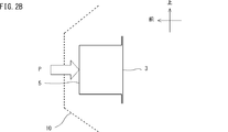
- FIG. 2A is a cross-sectional view of the bumper beam of case 1.
- FIG. 2B is a cross-sectional view of the bumper beam of case 2.
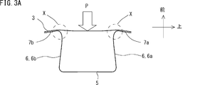
- FIG. 3A is a diagram showing a deformation behavior of the bumper beam of case 1 and showing an initial state.
- FIG. 3B is a diagram illustrating a state in which the state proceeds from the state illustrated in FIG. 3A.
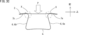
- FIG. 3C is a diagram illustrating a state in which the state proceeds from the state illustrated in FIG. 3B.
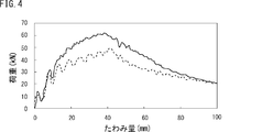
- FIG. 4 is a load-deflection diagram for case 1 and case 2.
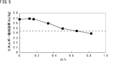
- FIG. FIG. 5 is a diagram showing the relationship between the position of the intermediate plate and the energy absorption efficiency.
- FIG. 5 is a diagram showing the relationship between the position of the intermediate plate and the energy absorption efficiency.
- FIG. 6A is a diagram illustrating a deformation behavior of the bumper beam according to the first embodiment and is a diagram illustrating an initial state.
- 6B is a diagram illustrating a state in which the state proceeds from the state illustrated in FIG. 6A.
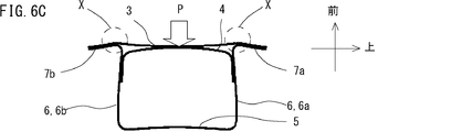
- FIG. 6C is a diagram illustrating a state in which the state proceeds from the state illustrated in FIG. 6B.
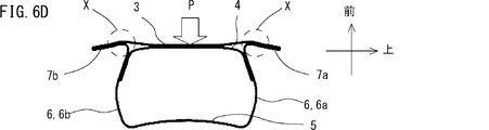
- FIG. 6D is a diagram illustrating a state in which the state proceeds from the state illustrated in FIG. 6C.
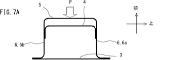
- FIG. 7A is a diagram illustrating a deformation behavior of the bumper beam of case 2 to which an intermediate plate is added, and is a diagram illustrating an initial state.
- FIG. 7B is a diagram illustrating a state in which the state proceeds from the state illustrated in FIG. 7A.
- FIG. 7C is a diagram illustrating a state in which the state proceeds from the state illustrated in FIG. 7B.
- FIG. 7D is a diagram illustrating a state in which the state proceeds from the state illustrated in FIG. 7C.
- FIG. 8 is a plan view of a bumper beam in which a concentrated load is applied at the center in the longitudinal direction.
- FIG. 9 is a cross-sectional view of the bumper beam of the second embodiment as viewed from above the vehicle.
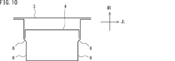
- FIG. 10 is a diagram illustrating an example of a joint portion between the vertical wall portion and the intermediate plate.
- FIG. 11A is a cross-sectional view of a bumper beam according to an example of the present invention.
- FIG. 11B is a cross-sectional view of the bumper beam of Comparative Example 1.
- FIG. 11C is a cross-sectional view of the bumper beam of Comparative Example 2.
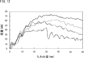
- FIG. 12 is a load-deflection curve of each bumper beam in the first embodiment.
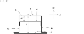
- FIG. 13 is a cross-sectional view of the bumper beam of Comparative Example 3 and Comparative Example 4.
- FIG. 14 is a load-deflection curve of each bumper beam in the second embodiment.
- FIG. 15 is a load-deflection curve of each bumper beam in the third embodiment.
- the bumper beam according to the present embodiment includes a first member, a second member, and an intermediate plate.
- the first member includes a top plate portion, two vertical wall portions, and two flange portions.
- the two vertical wall portions are connected to both side portions of the top plate portion.
- the two flange portions are connected to the two vertical wall portions, respectively.
- the second member is plate-shaped, joined to the two flange portions of the first member, and closes between at least two flange portions.
- the intermediate plate is joined to the two vertical wall portions of the first member, and is disposed substantially parallel to the second member in a space formed by the first member and the second member.
- a 2nd member is arrange
- the maximum load allowed by the bumper beam refers to a load applied to the bumper beam when the vertical wall portion of the bumper beam buckles (hereinafter referred to as “maximum allowable load”).
- the energy absorption efficiency is a value obtained by dividing the energy absorbed by the bumper beam when a collision load is applied by the mass of the bumper beam.
- the ratio d1 / h between the distance h between the second member and the top plate portion of the first member and the distance d1 between the second member and the middle plate is 0. As mentioned above, it is preferable that it is 0.6 or less. More preferably, the ratio d1 / h between the distance h between the second member and the top plate portion of the first member and the distance d1 between the second member and the middle plate is 0 or more and 0.2 or less.
- the interval h corresponds to the depth from the second member to the top plate portion of the first member.
- the interval d1 corresponds to the depth from the second member to the middle plate.
- the vertical wall portion buckles before the top plate portion cracks, and the bumper beam is not easily broken. As a result, it is possible to suppress a significant decrease in energy absorption efficiency due to the breakage of the bumper beam.
- the first member and the middle plate are made of metal plates, and the ratio t2 / t1 between the thickness t1 of the first member and the thickness t2 of the middle plate is 0.7 or more and 1.0 or less. Is preferred. Further, the ratio TS2 / TS1 between the tensile strength TS1 of the first member and the tensile strength TS2 of the intermediate plate is preferably 0.4 or more and 1.0 or less.
- the strength of the middle plate is lower than that of the first member, when the concentrated load is applied to the center in the longitudinal direction of the bumper beam, the vertical wall portion buckles before the top plate portion cracks. A significant decrease in energy absorption efficiency due to the fracture of the bumper beam can be further suppressed.
- the intermediate plate and the vertical wall are joined by welding.
- the end portion of the intermediate plate is bent, and the bent end portion and the vertical wall portion are joined in an overlapped state. In this case, if the end portion of the intermediate plate is bent toward the first member, the intermediate plate is easily bent toward the second member.
- the first member and the second member are made of a steel plate, and the tensile strength of the steel plate is 1 GPa or more. Thereby, a bumper beam suitable for automobiles can be obtained.
- the bumper beam described above is applied to vehicles.
- the vehicle includes the bumper beam described above at the front or rear of the vehicle.
- the second member of the bumper beam is disposed toward the outside of the vehicle.
- FIG. 1 is a cross-sectional view of the bumper beam 1 of the first embodiment.
- the letter “up” indicates the upper side of the vehicle, and the letter “front” indicates the front of the vehicle.
- a bumper beam 1 is disposed inside a bumper 10 of a vehicle.
- the bumper beam 1 includes a first member 2, a second member 3 and an intermediate plate 4.
- the bumper beam 1 of the first embodiment has a cross-sectional shape shown in FIG. 1 and extends in the width direction of the vehicle.
- the first member 2 includes a top plate portion 5, vertical wall portions 6a and 6b, and flange portions 7a and 7b. One end of each of the two vertical wall portions 6 a and 6 b is connected to each of both side portions 5 a and 5 b of the top plate portion 5. The other ends of the vertical wall portions 6a and 6b are connected to the flange portions 7a and 7b, respectively.
- the cross-sectional shape of the first member 2 is a hat-shaped open cross section. That is, the space between the two flange portions 7a and 7b is open.
- the first member 2 is formed by press-molding a metal plate.
- the second member 3 is a plate-like member, for example, formed by punching a metal plate.
- a joint portion is provided between the second member 3 and the first member 2.
- the 2nd member 3 is joined to the flange parts 7a and 7b of the 1st member 2, and closes between the flange parts 7a and 7b. That is, the first member 2 and the second member 3 joined to each other form a closed cross section.
- the intermediate plate 4 is disposed substantially parallel to the second member 3 in a space formed by the first member 2 and the second member 3.
- a joint portion is provided between the intermediate plate 4 and the first member 2.
- the end portions 4a and 4b of the intermediate plate 4 are bent at substantially right angles and joined to the upper and lower vertical wall portions 6a and 6b, respectively.
- the end portions 4 a and 4 b of the middle plate 4 are arranged toward the top plate portion 5.
- the intermediate plate 4 is formed by press-molding a metal plate. Such an intermediate plate 4 restrains the deformation of the vertical wall portions 6a and 6b. Therefore, the vertical wall portions 6a and 6b are not easily buckled.
- the intermediate plate 4 does not need to be strictly parallel to the second member 3 and allows a slight inclination. This inclination is, for example, 10 ° or less.
- the intermediate plate 4 may be provided with beads along the vertical direction of the vehicle or embossed. Since the rigidity of the intermediate plate is improved by these processes, the intermediate plate 4 further restrains the deformation of the vertical wall portions 6a and 6b. As a result, the vertical wall portions 6a and 6b are less likely to buckle, and an improvement in energy absorption efficiency can be expected.
- Such a bumper beam 1 is arranged with the second member 3 facing the outside of the vehicle.
- the second member 3 is disposed toward the front of the vehicle.
- the top plate portion 5, the second member 3, and the middle plate 4 of the first member 2 are in a posture in which they stand up in the vehicle vertical direction.
- the vertical wall portions 6a and 6b of the first member 2 are vertically oriented along the vehicle front-rear direction.
- the bumper beam 1 When the bumper beam 1 is arranged on the vehicle, two arrangement forms are conceivable.
- the first is a case where the second member 3 is arranged toward the outside of the vehicle as shown in FIG. 1 (hereinafter referred to as case 1).
- the second is a case where the top plate portion 5 of the first member 2 is arranged toward the outside of the vehicle as described in Patent Document 2 and Patent Document 3 (hereinafter referred to as Case 2).
- Case 1 the present inventors investigated energy absorption efficiency by dynamic three-point bending simulation analysis for Case 1 and Case 2.
- FIG. 2A and 2B are cross-sectional views of the bumper beam model used in the dynamic three-point bending simulation analysis.
- FIG. 2A shows the case of the bumper beam of case 1
- FIG. 2B shows the case of the bumper beam of case 2.
- the models of case 1 and case 2 do not have an intermediate plate 4.
- a load P in the direction toward the top plate portion 5 was applied to the center in the longitudinal direction of the second member 3 over the entire vertical direction.
- FIG. 2B in case 2, a load P in the direction toward the second member 3 is applied to the center in the longitudinal direction of the top plate portion 5 over the entire vertical direction.
- the deformation behavior of the bumper beam was analyzed.
- the relationship between the load P and the deflection amount was examined for each bumper beam.
- the amount of deflection refers to the amount of deflection at the portion where the load P is applied.
- the load speed was 9 km / h and the distance between the fulcrums was 800 mm.
- the analysis results are shown in FIGS. 3A to 3C and FIG.
- FIGS. 3A, 3B, and 3C are diagrams showing the deformation behavior of the bumper beam of case 1.
- FIG. The deformation of the bumper beam proceeds in the order shown in FIGS. 3A, 3B, and 3C.
- 3A to 3C when a load P is applied to the second member 3, a bumper is provided in the vicinity of the end X of the vertical wall portions 6a and 6b (hereinafter also collectively referred to as the vertical wall portion 6).
- a compressive force acts along the longitudinal direction of the beam.
- the compression force refers to a force for contracting each of the two vertical wall portions 6 in the longitudinal direction of the bumper beam. Due to the action of the compressive force, the end X on the second member 3 side of the vertical wall portion 6 moves toward the center in the vehicle vertical direction. As a result, the vertical wall portion 6 is deformed and finally buckles.
- FIG. 4 is a load-deflection diagram for the bumper beams of Case 1 and Case 2.
- the vertical axis represents the load, and the horizontal axis represents the amount of deflection.
- the solid line indicates the result of the bumper beam of case 1
- the broken line indicates the result of the bumper beam of case 2.
- the following is shown from the load-deflection diagram shown in FIG.
- case 1 the maximum load is obtained when the amount of deflection is about 38 mm.
- the maximum load is about 62 kN.
- the maximum load is obtained when the amount of deflection is about 42 mm.
- the maximum load is about 50 kN.
- case 1 When the amount of deflection is about 42 mm or more, the vertical wall portion 6 buckles. From this, it can be seen that the maximum allowable load of case 1 is higher than the maximum allowable load of case 2. However, the case 1 has a smaller amount of deflection leading to buckling than the case 2. In other words, the case 1 has a buckling occurrence timing earlier than the case 2.
- the energy absorbed by the bumper beam is equal to the integrated value of the load-deflection curve in FIG. Therefore, in order to increase the energy absorption efficiency of the bumper beam, it is only necessary to increase the maximum allowable load and delay the buckling occurrence timing.
- the bumper beam of Case 1 has a higher maximum allowable load than Case 2 due to its structure. Therefore, the present inventors studied to delay the buckling occurrence timing of the bumper beam of case 1 and increase the energy absorption efficiency.
- the bumper beam of the case 1 is moved to the center of the bumper beam in the vertical direction of the vehicle at an early stage by the compressive force acting on the vertical wall portion 6, so that the vertical wall The part 6 is deformed and buckled. That is, if the movement of the end portion X is suppressed, it is possible to suppress the vertical wall portion 6 from buckling early. Therefore, as shown in FIG. 1, the bumper beam 1 according to the present embodiment has an intermediate plate 4 disposed substantially parallel to the second member 3 in a space formed by the first member 2 and the second member 3. The end portions 4a and 4b of the intermediate plate 4 are joined to the upper and lower vertical wall portions 6a and 6b, respectively. The middle plate 4 suppresses deformation of the vertical wall portion 6.
- the vertical wall portion 6 is not easily deformed. That is, the vertical wall portion 6 is not easily buckled. Thereby, the buckling generation timing of the bumper beam 1 is delayed. Further, since the bumper beam 1 is arranged with the second member 3 facing the outside of the vehicle, the maximum allowable load of the bumper beam 1 is high as in the case 1. In short, if the intermediate plate 4 is added to the bumper beam of the case 1 having a high maximum allowable load, buckling of the vertical wall portion 6 is suppressed, so that the timing of occurrence of buckling of the vertical wall portion 6 is late. Thereby, the energy absorption efficiency of the bumper beam 1 becomes high.
- the position of the middle plate 4 is preferably closer to the second member 3. Specifically, referring to FIG. 1, it is preferable that the ratio d1 / h with respect to the intermediate plate 4 is 0 or more and 0.6 or less.
- h represents the distance between the second member 3 and the top plate portion 5 of the first member 2
- d1 represents the distance between the second member 3 and the middle plate 4. This point will be described with reference to FIG.
- FIG. 5 is a diagram showing the energy absorption efficiency of bumper beams having different ratios d1 / h related to the position of the intermediate plate 4.
- the results shown in FIG. 5 were obtained by the same dynamic three-point bending simulation analysis as described above. Simulation analysis was performed on each bumper beam in which the ratio d1 / h related to the position of the middle plate 4 of the bumper beam shown in FIG. Other analysis conditions were the same as the simulation analysis shown in FIGS. 3A to 3C and FIG.
- the energy absorption efficiency shows a maximum value when the ratio d1 / h is about 0.16. As the ratio d1 / h is greater than 0.16, the energy absorption efficiency decreases.
- the energy absorption efficiency of the bumper beam not having the intermediate plate 4 is 0.44 kJ / kg (see the broken line in FIG. 5). If the ratio d1 / h is larger than 0.65, the energy absorption efficiency of the bumper beam having the intermediate plate 4 is less than the energy absorption efficiency of the bumper beam not having the intermediate plate 4. Therefore, the middle plate 4 is preferably arranged at a position where the ratio d1 / h with respect to the middle plate 4 is 0 or more and 0.6 or less.
- the present inventors investigated the deformation behavior of a bumper beam having a ratio d1 / h of 0.16 by dynamic three-point bending simulation analysis.
- the analysis conditions were the same as the simulation analysis shown in FIGS. 3A to 3C and FIG.
- the analysis results are shown in FIGS. 6A to 6D.
- FIGS. 6A to 6D are diagrams showing the deformation behavior of the bumper beam of the first embodiment.
- the deformation of the bumper beam having the ratio d1 / h of 0.16 proceeds in the order shown in FIGS. 6A, 6B, 6C, and 6D.
- FIGS. 6A to 6D when load P is applied to second member 3, a compressive force is applied to vertical wall portion 6, so that end X of vertical wall portion 6 is a bumper as described above.
- the beam moves toward the center of the vehicle in the vertical direction. Since the intermediate plate 4 is joined to the vertical wall portion 6, it is compressed as the end portion X moves. At this time, the intermediate plate 4 bends toward the second member 3 side. Therefore, the second member 3 and the intermediate plate 4 are in contact with each other.
- the middle plate 4 comes into contact with the second member 3, the deflection of the second member 3 is restricted by the middle plate 4, so that the movement of the end X of the vertical wall portion 6 is also restricted.
- buckling of the vertical wall portion 6 is further suppressed. That is, when the ratio d1 / h is 0.2 or less, the buckling of the vertical wall portion 6 is not only suppressed by the intermediate plate 4 but also the effect of the contact between the intermediate plate 4 and the second member 3 as described above. Will be added. Therefore, the maximum allowable load of the bumper beam 1 is further improved.
- the intermediate plate 4 is in contact with the second member 3 before the load P is applied.
- the deformation modes of the second member 3 and the intermediate plate 4 are different. That is, the second member 3 and the intermediate plate 4 are bent together. Therefore, the energy absorption efficiency is reduced as compared with the case where the ratio d1 / h is 0.16. Therefore, a preferable lower limit of the ratio d1 / h is 0.1.
- the energy absorption efficiency of the bumper beam when the ratio d1 / h is 0 is higher than the energy absorption efficiency of the bumper beam that does not have the intermediate plate 4. Therefore, the ratio d1 / h may be zero.
- FIGS. 7A to 7D are diagrams showing the deformation behavior of the bumper beam of case 2 to which an intermediate plate is added. That is, the top plate portion 5 of the first member 2 is arranged facing the outside of the vehicle. The deformation of the bumper beam proceeds in the order shown in FIGS. 7A, 7B, 7C, and 7D.
- FIGS. 7A to 7D in case 2, when load P is applied to top plate portion 5, upper vertical wall portion 6a bends upward in the vehicle, and lower vertical wall portion 6b Bend down. Therefore, a tensile force acts on the middle plate 4 in the vehicle vertical direction. In this case, since the middle plate 4 is difficult to bend, the top plate portion 5 and the middle plate 4 are difficult to contact. Therefore, it is difficult to limit the deflection of the surface receiving the load due to the contact between the intermediate plate 4 and the surface receiving the load as in the case 1. That is, it is difficult to suppress buckling of the vertical wall portion 6 in the case 2.
- the bumper beam of the first embodiment has high energy absorption efficiency because the middle plate suppresses buckling of the vertical wall portion. However, if the buckling of the vertical wall part is suppressed too much, when a concentrated load is applied to the longitudinal center of the bumper beam, the top plate part of the first member on the back side cracks before the vertical wall part buckles. May occur. Even if the vertical wall is not buckled, if the top plate is cracked, the energy absorption efficiency of the bumper beam is greatly reduced.
- FIG. 8 is a plan view of a bumper beam in which a concentrated load is applied at the center in the longitudinal direction.
- the letter “right” indicates the right side of the vehicle.
- FIG. 8 when concentrated load P is applied to the center in the longitudinal direction of the bumper beam, the vicinity of the region where concentrated load P is applied bends toward the rear of the vehicle (inward of the vehicle).
- the top plate portion 5 of the first member since the top plate portion 5 of the first member is disposed on the back side of the bumper beam, it receives a force in the pulling direction (the left-right direction of the vehicle). If the force in the tension direction is too large, the top plate portion 5 will crack.
- the top plate portion 5 is cracked prior to the buckling of the vertical wall portion 6.
- the top plate portion 5 is likely to crack.
- the position of the middle plate is limited in the longitudinal direction of the bumper beam in order to suppress cracks in the top plate portion.
- the present inventors obtained a suitable position of the intermediate plate in the longitudinal direction of the bumper beam according to Example 3 described later. This point will be described with reference to FIG.
- FIG. 9 is a cross-sectional view of the bumper beam of the second embodiment as seen from above the vehicle.
- L be the total length of bumper beam 10
- L be any distance from center C in the longitudinal direction of bumper beam 10.
- the middle plate 4 of the bumper beam 10 of the second embodiment is disposed in a central region of ⁇ L1 or more and L1 or less from the center C in the longitudinal direction of the bumper beam 10.
- the middle plate 4 may be disposed in the entire central region or may be disposed in a part of the central region.
- the distance L1 is preferably 0.2 ⁇ L, and more preferably 0.1 ⁇ L.
- the length L1 is divided into a positive value and a negative value in the vehicle left-right direction, with the center C in the longitudinal direction of the bumper beam being 0.
- the middle plate is arranged from the center C in the longitudinal direction of the bumper beam to a region separated by a distance L1 on both sides in the vehicle left-right direction.
- the end X of the vertical wall portion 6 in the region in which the intermediate plate is not disposed is directed toward the vehicle vertical direction center of the bumper beam. It becomes easy to move (see FIGS. 6A to 6D). As a result, the buckling occurrence timing of the vertical wall portion is accelerated. As a result, buckling occurs in the vertical wall portion before the crack in the top plate portion occurs, so that a significant decrease in energy absorption efficiency due to the fracture of the bumper beam can be suppressed.
- the thickness t2 of the intermediate plate 4 is preferably equal to or less than the thickness t1 of the first member 2. This is for optimizing the timing of occurrence of buckling of the vertical wall portion 6 and suppressing the top plate portion 5 from cracking.
- the ratio t2 / t1 between the plate thickness t1 of the first member 2 and the plate thickness t2 of the intermediate plate 4 is preferably 0.7 or more and 1.0 or less.
- the ratio t2 / t1 is less than 0.7, since the strength of the intermediate plate 4 is low, the vertical wall portion 6 buckles early. If the ratio t2 / t1 is larger than 1.0, the strength of the intermediate plate 4 is high, and therefore, when the concentrated load P is applied to the center in the longitudinal direction of the bumper beam, the top plate portion 5 is likely to crack.
- the preferable lower limit of the ratio t2 / t1 is 0.8, and the preferable upper limit is 0.9.
- the tensile strength TS2 of the middle plate 4 is equal to or lower than the tensile strength TS1 of the first member 2 in order to suppress cracking in the top plate portion 5.
- the ratio TS2 / TS1 between the tensile strength TS1 of the first member 2 and the tensile strength TS2 of the intermediate plate 4 is preferably 0.4 or more and 1.0 or less. If the ratio TS2 / TS1 is less than 0.4, the strength of the intermediate plate 4 is low, so that the vertical wall portion 6 buckles early.
- the ratio TS2 / TS1 is greater than 1.0, the strength of the intermediate plate 4 is high, so that when the concentrated load P is applied to the center in the longitudinal direction of the bumper beam, the end X of the vertical wall portion 6 becomes the bumper beam. It is difficult to move toward the center in the vertical direction of the vehicle (see FIGS. 6A to 6D). As a result, the top plate portion 5 tends to crack before the vertical wall portion 6 buckles.
- the preferable lower limit of the ratio TS2 / TS1 is 0.6, and the preferable upper limit is 0.8.
- Joining of the intermediate plate 4 and the vertical wall 6 includes, for example, welding.
- welding method include spot welding, plug welding, arc welding, and laser welding.
- the joining of the intermediate plate 4 and the vertical wall portion 6 is not limited to welding.
- the middle plate 4 and the vertical wall portion 6 may be joined by mechanical joining. Mechanical joining is, for example, rivets, bolts and nuts, screws, and the like. Further, the middle plate 4 and the vertical wall portion 6 may be joined with an adhesive. The same applies to the joining of the first member 2 and the second member 3.
- the second member 3 is arranged toward the outside of the vehicle.
- the bumper beam is curved in the longitudinal direction.
- an outer arc of the curved bumper beam (the second member 3 side in FIG. 9) is arranged toward the outside of the vehicle.
- the bumper beam is attached to a crash box, a front side member, or the like disposed inside the vehicle. For this reason, a mounting hole or the like is provided on the inner surface of the bumper beam. In short, even if the bumper beam is not attached to the vehicle, it can be determined which component of the first member or the second member of the bumper beam is arranged toward the outside of the vehicle.
- FIG. 10 is a diagram illustrating an example of a joint portion between the vertical wall portion and the intermediate plate.
- a step 8 for positioning the intermediate plate 4 may be provided on the vertical wall portion 6.
- the size of the step 8 is about 0.5 mm to several mm. If the step 8 is less than 0.5 mm, it is difficult to position the intermediate plate 4. If the level difference 8 is too large, the rigidity of the vertical wall portion 6 changes, so that the deformation behavior of the bumper beam changes. In short, the step 8 of the vertical wall portion 6 is provided in a range where the deformation behavior of the bumper beam does not change. By providing the step 8 on the vertical wall portion 6, it is easy to install the intermediate plate and to manufacture the bumper beam.
- the metal plate is, for example, a steel plate, an aluminum plate, a titanium plate, a magnesium plate, a copper plate, a nickel plate or an alloy plate thereof, a multilayer metal plate, or the like.
- the first member and the second member are preferably made of a steel plate having a tensile strength of 1 GPa or more. In this case, the strength of the bumper beam can be further increased, and the safety of the vehicle body is further improved.
- the bumper beam of the present embodiment is not limited to the bumper beam of the front bumper.
- the bumper beam of the present embodiment may be disposed at the rear part of the vehicle. That is, the bumper beam of this embodiment can be applied to a rear bumper or the like.
- the second member of the bumper beam is arranged toward the outside of the vehicle.
- Example 1 load load simulation analysis was performed on bumper beams having different arrangements of the middle plate 4 to examine energy absorption efficiency.
- FIG. 11A to 11C are cross-sectional views of the bumper beam analysis model used in Example 1.
- FIG. FIG. 11A shows the model of Invention Example 1 and Invention Example 2
- FIG. 11B shows the model of Comparative Example 1
- FIG. 11C shows the model of Comparative Example 2.
- the ratio d1 / h related to the position of the middle plate 4 in Invention Example 1 was set to 0.16
- the ratio d1 / h related to the position of the middle plate 4 in Invention Example 2 was set to 0.5.
- the bumper beam which does not have the intermediate plate 4 was assumed.
- Comparative Example 2 a bumper beam in which the intermediate plate 4 is arranged perpendicular to the second member 3 is assumed.
- the width W1 of the vertical wall portion 6 of the first member 2 was 60 mm
- the width W2 of the top plate portion 5 was 80 mm
- the width W3 of the second member 3 was 120 mm.
- the load P was applied toward the first member 2 at the center of the second member 3.
- the first member 2, the second member 3 and the intermediate plate 4 were assumed to be steel plates having a tensile strength of 1800 MPa and a plate thickness of 1.4 mm.
- FIG. 12 is a load-deflection curve for each bumper beam of Example 1.
- the solid line indicates the result of the present invention example 1
- the broken line indicates the present invention example 2
- the one-dot chain line indicates the comparative example 1
- the two-dot chain line indicates the comparative example 2.
- the vertical wall portion 6 did not buckle until the deflection amount was about 38 mm.
- the vertical wall portion 6 buckled before the deflection amount reached 30 mm.
- the maximum allowable load was about 73 kN
- Example 2 of the present invention the maximum allowable load was about 62 kN.
- the maximum allowable load was about 45 kN
- Comparative Example 2 the maximum allowable load was about 58 kN.
- the energy absorption efficiency of Invention Example 1 was 0.68 kJ / kg, and the energy absorption efficiency of Invention Example 2 was 0.56 kJ / kg.
- the energy absorption efficiency of Comparative Example 1 was 0.44 kJ / kg, and the energy absorption efficiency of Comparative Example 2 was 0.51 kJ / kg.
- Example 2 the maximum allowable load was compared between the bumper beam of case 1 to which the intermediate plate 4 was added and the bumper beam of case 2 to which the intermediate plate 4 was added.
- Example 2 the results of Example 2 of the present invention in Example 1 were cited, and as Comparative Example 3 and Comparative Example 4, an intermediate plate 4 was disposed on the bumper beam of Case 2, and the same load load as in Example 1 was obtained. Simulation analysis was performed.
- FIG. 13 is a cross-sectional view of the bumper beam of Case 2 to which the intermediate plate 4 used in Example 2 is added.
- the ratio d2 / h related to the position of the middle plate 4 of Comparative Example 3 was set to 0.33, and the ratio d2 / h related to the position of the middle plate 4 of Comparative Example 4 was set to 0.5.
- the load P was added to the center of the top plate part 5.
- d2 indicates the distance between the top plate portion 5 and the middle plate 4. That is, the distance d ⁇ b> 2 corresponds to the depth from the top plate portion 5 to the middle plate 4.
- FIG. 14 is a load-deflection curve for each bumper beam of Example 2.
- Example 2 of the present invention performed in Example 1 is also shown in FIG.
- the solid line represents Example 2 of the present invention
- the one-dot chain line represents Comparative Example 3
- the two-dot chain line represents Comparative Example 4.
- the maximum allowable load of both Comparative Example 3 and Comparative Example 4 was about 48 kN.
- Example 3 a load load simulation analysis was performed on a bumper beam in which a region in which the middle plate 4 is arranged in the longitudinal direction was limited, and whether or not cracks occurred in the top plate portion was examined.
- the width W1 of the vertical wall portion 6 of the first member 2 was 90 mm
- the width W2 of the top plate portion 5 was 80 mm
- the width W3 of the second member 3 was 120 mm.
- the simulation analysis similar to Example 1 was performed by changing the distance L1 of the bumper beam 10 of the second embodiment shown in FIG.
- FIG. 15 is a load-deflection curve for each bumper beam of Example 3.
- the solid line indicates the result of the bumper beam whose distance L1 is 0.06 ⁇ L.
- the broken line shows the result of the bumper beam whose distance L1 is 0.2 ⁇ L.
- a one-dot chain line indicates a result of the bumper beam having a distance L1 of 0.5 ⁇ L.
- the amount of deflection was about 100 mm, and the top plate was cracked.
- the deflection amount was about 95 mm, and a crack occurred in the top plate portion.
Abstract
Description
図1は、第1実施形態のバンパービーム1の断面図である。図1中、文字「上」は車両の上方を示し、文字「前」は車両の前方を示す。以下の図においても同様である。図1を参照して、バンパービーム1は、車両のバンパー10の内側に配置される。バンパービーム1は、第1部材2、第2部材3及び中板4を備える。第1実施形態のバンパービーム1は、図1に示す断面形状を有し、車両の幅方向に延在する。
第1実施形態のバンパービームは、中板が縦壁部の座屈を抑制するため、エネルギー吸収効率が高い。しかし、縦壁部の座屈を抑制しすぎると、バンパービームの長手方向の中央に集中荷重が負荷されたとき、縦壁部が座屈する前に背面側の第1部材の天板部に亀裂が生じることがある。たとえ縦壁部が座屈しなくても、天板部に亀裂が生じれば、バンパービームのエネルギー吸収効率は大きく低下する。

2 第1部材
3 第2部材
4 中板
41 第1中板
42 第2中板
5 天板部
6a、6b 縦壁部
7a、7b フランジ部
8 縦壁部の段差
d1 第2部材と中板との間隔
d2 天板部と中板との間隔
h 第2部材と天板部との間隔
L バンパービーム全長
P 衝突荷重
X 縦壁部の端部
Claims (10)
- 天板部、前記天板部の両側部のそれぞれに繋がる2つの縦壁部、及び前記2つの縦壁部それぞれに繋がる2つのフランジ部を含む第1部材と、
前記第1部材の前記2つのフランジ部に接合され、少なくとも前記2つのフランジ部同士の間を閉じる板状の第2部材と、
前記第1部材の前記2つの縦壁部に接合され、前記第1部材及び前記第2部材により形成される空間内に、前記第2部材に略平行に配置される中板と、を備え、
前記第1部材及び前記第2部材のうち前記第2部材が車両の外側に向けて配置される、車両用バンパービーム。 - 請求項1に記載の車両用バンパービームであって、
前記第2部材と前記第1部材の前記天板部との間隔hと、前記第2部材と前記中板との間隔d1との比d1/hが、0以上、0.6以下である、車両用バンパービーム。 - 請求項1に記載の車両用バンパービームであって、
前記第2部材と前記第1部材の前記天板部との間隔hと、前記第2部材と前記中板との間隔d1との比d1/hが、0以上、0.2以下である、車両用バンパービーム。 - 請求項2又は請求項3に記載の車両用バンパービームであって、
前記バンパービームの全長をLとしたとき、前記バンパービームの長手方向の中央から-0.2×L以上、0.2×L以下の領域の少なくとも一部に、前記中板が配置される、車両用バンパービーム。 - 請求項2又は請求項3に記載の車両用バンパービームであって、
前記バンパービームの全長をLとしたとき、前記バンパービームの長手方向の中央から-0.1×L以上、0.1×L以下の領域の少なくとも一部に、前記中板が配置される、車両用バンパービーム。 - 請求項1~請求項5のいずれか1項に記載の車両用バンパービームであって、
前記第1部材及び前記中板は金属板からなり、
前記第1部材の板厚t1と、前記中板の板厚t2との比t2/t1が、0.7以上、1.0以下である、車両用バンパービーム。 - 請求項1~請求項6のいずれか1項に記載の車両用バンパービームであって、
前記第1部材の引張強さTS1と、前記中板の引張強さTS2との比TS2/TS1が、0.4以上、1.0以下である、車両用バンパービーム。 - 請求項1~請求項7のいずれか1項に記載の車両用バンパービームであって、
前記中板と前記縦壁部とが溶接によって接合されている、車両用バンパービーム。 - 請求項1~請求項8のいずれか1項に記載の車両用バンパービームであって、
前記第1部材及び前記第2部材は鋼板からなり、前記鋼板の引張強度が1GPa以上である、車両用バンパービーム。 - 請求項1~請求項9のいずれか1項に記載の車両用バンパービームを前部又は後部に備え、前記バンパービームの前記第2部材が車両の外側に向けて配置される、車両。
Priority Applications (9)
| Application Number | Priority Date | Filing Date | Title |
|---|---|---|---|
| EP16739944.3A EP3248845A4 (en) | 2015-01-21 | 2016-01-19 | Bumper beam |
| BR112017014184A BR112017014184A2 (pt) | 2015-01-21 | 2016-01-19 | viga de para-choque |
| JP2016570551A JP6402781B2 (ja) | 2015-01-21 | 2016-01-19 | バンパービーム |
| RU2017129254A RU2674366C1 (ru) | 2015-01-21 | 2016-01-19 | Балка бампера и транспортное средство, содержащее упомянутую балку |
| CN201680006411.9A CN107206951B (zh) | 2015-01-21 | 2016-01-19 | 保险杠横梁 |
| US15/543,313 US10259410B2 (en) | 2015-01-21 | 2016-01-19 | Bumper beam |
| CA2974327A CA2974327C (en) | 2015-01-21 | 2016-01-19 | Bumper beam |
| KR1020177022798A KR101965091B1 (ko) | 2015-01-21 | 2016-01-19 | 범퍼 빔 |
| MX2017009446A MX2017009446A (es) | 2015-01-21 | 2016-01-19 | Viga de parachoques. |
Applications Claiming Priority (2)
| Application Number | Priority Date | Filing Date | Title |
|---|---|---|---|
| JP2015-009105 | 2015-01-21 | ||
| JP2015009105 | 2015-01-21 |
Publications (1)
| Publication Number | Publication Date |
|---|---|
| WO2016117335A1 true WO2016117335A1 (ja) | 2016-07-28 |
Family
ID=56416887
Family Applications (1)
| Application Number | Title | Priority Date | Filing Date |
|---|---|---|---|
| PCT/JP2016/000257 WO2016117335A1 (ja) | 2015-01-21 | 2016-01-19 | バンパービーム |
Country Status (11)
| Country | Link |
|---|---|
| US (1) | US10259410B2 (ja) |
| EP (1) | EP3248845A4 (ja) |
| JP (1) | JP6402781B2 (ja) |
| KR (1) | KR101965091B1 (ja) |
| CN (1) | CN107206951B (ja) |
| BR (1) | BR112017014184A2 (ja) |
| CA (1) | CA2974327C (ja) |
| MX (1) | MX2017009446A (ja) |
| RU (1) | RU2674366C1 (ja) |
| TW (1) | TWI609803B (ja) |
| WO (1) | WO2016117335A1 (ja) |
Cited By (4)
| Publication number | Priority date | Publication date | Assignee | Title |
|---|---|---|---|---|
| WO2018173759A1 (ja) | 2017-03-23 | 2018-09-27 | 新日鐵住金株式会社 | バンパービーム |
| WO2019035185A1 (ja) * | 2017-08-15 | 2019-02-21 | 新日鐵住金株式会社 | バンパービーム及び車両 |
| WO2019072653A1 (de) * | 2017-10-09 | 2019-04-18 | Kirchhoff Automotive Deutschland Gmbh | Stossfängerquerträger |
| WO2020053626A1 (en) * | 2018-09-12 | 2020-03-19 | Arcelormittal | Bumper beam having steel reinforcement |
Families Citing this family (4)
| Publication number | Priority date | Publication date | Assignee | Title |
|---|---|---|---|---|
| RU2673220C1 (ru) * | 2015-07-08 | 2018-11-22 | Ниппон Стил Энд Сумитомо Метал Корпорейшн | Усилитель бампера и транспортное средство, содержащее такой усилитель бампера |
| KR20200018275A (ko) * | 2018-08-10 | 2020-02-19 | 롬엔드하스전자재료코리아유한회사 | 유기 전계 발광 화합물 및 이를 포함하는 유기 전계 발광 소자 |
| KR102342441B1 (ko) * | 2019-08-05 | 2021-12-22 | 부산대학교 산학협력단 | 전기 변색 소재, 이의 제조방법 및 이를 포함하는 전기 변색 소자 제조 방법 |
| CN113268814B (zh) * | 2021-06-18 | 2022-05-17 | 中国第一汽车股份有限公司 | 一种保险杠总成表面刚度的设计方法 |
Citations (2)
| Publication number | Priority date | Publication date | Assignee | Title |
|---|---|---|---|---|
| JPH06328988A (ja) * | 1993-03-23 | 1994-11-29 | Toupure Kk | 車両用バンパービーム |
| JP2010023658A (ja) * | 2008-07-18 | 2010-02-04 | Sumitomo Metal Ind Ltd | バンパーリインフォースメントおよびその製造方法 |
Family Cites Families (15)
| Publication number | Priority date | Publication date | Assignee | Title |
|---|---|---|---|---|
| JPH06171441A (ja) * | 1992-10-09 | 1994-06-21 | Nkk Corp | バンパービームおよびバンパー |
| JPH07309184A (ja) | 1994-05-20 | 1995-11-28 | Kobe Steel Ltd | 自動車用補強部材 |
| JP3120957B2 (ja) * | 1995-07-07 | 2000-12-25 | 本田技研工業株式会社 | 車両用バンパビームの製造方法 |
| TW459679U (en) * | 1998-07-21 | 2001-10-11 | Chen Chuen Mau | Bumper for vehicles |
| TW429908U (en) * | 1999-02-26 | 2001-04-11 | Li Ching Huang | Cushion device for automobile bumper |
| GB0114684D0 (en) * | 2001-06-15 | 2001-08-08 | Dow Chemical Co | Automobile assembly |
| US7407219B2 (en) * | 2004-03-24 | 2008-08-05 | Shape Corporation | Energy management beam |
| JP4057815B2 (ja) * | 2002-01-31 | 2008-03-05 | 株式会社アステア | バンパ補強材 |
| DE102006000481A1 (de) * | 2005-09-27 | 2007-04-05 | Tokai Rubber Industries, Ltd., Komaki | Stossabsorbierendes Element für Fahrzeuge |
| JP4735843B2 (ja) * | 2006-06-29 | 2011-07-27 | マツダ株式会社 | 自動車のバンパ構造 |
| JP4759497B2 (ja) * | 2006-11-29 | 2011-08-31 | 東海ゴム工業株式会社 | 自動車用衝撃吸収部材 |
| JP5329188B2 (ja) * | 2008-11-21 | 2013-10-30 | 株式会社アステア | バンパ補強材 |
| DE102010050960A1 (de) * | 2010-11-10 | 2012-05-10 | Gm Global Technology Operations Llc (N.D.Ges.D. Staates Delaware) | Stoßfängerquerträger für ein Kraftfahrzeug, Verstärkungsbauteil für einen Stoßfängerquerträger und Verfahren zur Herstellung eines Stoßfängerquerträgers |
| TWI451898B (zh) * | 2012-01-06 | 2014-09-11 | Yung Yu Chen | 齒輪傳動機構及使用該機構之遊戲機 |
| SE537087C2 (sv) * | 2013-03-13 | 2014-12-30 | Gestamp Hardtech Ab | Stötfångarbalk |
-
2016
- 2016-01-19 WO PCT/JP2016/000257 patent/WO2016117335A1/ja active Application Filing
- 2016-01-19 EP EP16739944.3A patent/EP3248845A4/en active Pending
- 2016-01-19 MX MX2017009446A patent/MX2017009446A/es unknown
- 2016-01-19 US US15/543,313 patent/US10259410B2/en active Active
- 2016-01-19 CN CN201680006411.9A patent/CN107206951B/zh active Active
- 2016-01-19 CA CA2974327A patent/CA2974327C/en not_active Expired - Fee Related
- 2016-01-19 RU RU2017129254A patent/RU2674366C1/ru not_active IP Right Cessation
- 2016-01-19 KR KR1020177022798A patent/KR101965091B1/ko active IP Right Grant
- 2016-01-19 JP JP2016570551A patent/JP6402781B2/ja active Active
- 2016-01-19 BR BR112017014184A patent/BR112017014184A2/pt not_active Application Discontinuation
- 2016-01-20 TW TW105101740A patent/TWI609803B/zh not_active IP Right Cessation
Patent Citations (2)
| Publication number | Priority date | Publication date | Assignee | Title |
|---|---|---|---|---|
| JPH06328988A (ja) * | 1993-03-23 | 1994-11-29 | Toupure Kk | 車両用バンパービーム |
| JP2010023658A (ja) * | 2008-07-18 | 2010-02-04 | Sumitomo Metal Ind Ltd | バンパーリインフォースメントおよびその製造方法 |
Non-Patent Citations (1)
| Title |
|---|
| See also references of EP3248845A4 * |
Cited By (16)
| Publication number | Priority date | Publication date | Assignee | Title |
|---|---|---|---|---|
| EP3604043A4 (en) * | 2017-03-23 | 2020-06-17 | Nippon Steel Corporation | BUMPER BEAM |
| KR20190111148A (ko) | 2017-03-23 | 2019-10-01 | 닛폰세이테츠 가부시키가이샤 | 범퍼 빔 |
| WO2018173759A1 (ja) | 2017-03-23 | 2018-09-27 | 新日鐵住金株式会社 | バンパービーム |
| US10766444B2 (en) | 2017-03-23 | 2020-09-08 | Nippon Steel Corporation | Bumper beam |
| JP6485606B1 (ja) * | 2017-08-15 | 2019-03-20 | 新日鐵住金株式会社 | バンパービーム及び車両 |
| US10994681B2 (en) | 2017-08-15 | 2021-05-04 | Nippon Steel Corporation | Bumper beam and vehicle |
| CN111032441A (zh) * | 2017-08-15 | 2020-04-17 | 日本制铁株式会社 | 保险杠横梁和车辆 |
| WO2019035185A1 (ja) * | 2017-08-15 | 2019-02-21 | 新日鐵住金株式会社 | バンパービーム及び車両 |
| JP2020536785A (ja) * | 2017-10-09 | 2020-12-17 | キルヒホフ オートモーティブ ドイチュラント ゲーエムベーハー | バンパークロスメンバ |
| WO2019072653A1 (de) * | 2017-10-09 | 2019-04-18 | Kirchhoff Automotive Deutschland Gmbh | Stossfängerquerträger |
| JP7012837B2 (ja) | 2017-10-09 | 2022-01-28 | キルヒホフ オートモーティブ ドイチュラント ゲーエムベーハー | バンパークロスメンバ |
| US11235720B2 (en) | 2017-10-09 | 2022-02-01 | Kirchhoff Automotive Deutschland Gmbh | Bumper crossmember |
| WO2020053799A1 (en) * | 2018-09-12 | 2020-03-19 | Arcelormittal | Bumper beam having steel reinforcement |
| WO2020053626A1 (en) * | 2018-09-12 | 2020-03-19 | Arcelormittal | Bumper beam having steel reinforcement |
| JP2022500298A (ja) * | 2018-09-12 | 2022-01-04 | アルセロールミタル | 鋼補強材を備えたバンパービーム |
| JP7165814B2 (ja) | 2018-09-12 | 2022-11-04 | アルセロールミタル | 鋼補強材を備えたバンパービーム |
Also Published As
| Publication number | Publication date |
|---|---|
| TW201641326A (zh) | 2016-12-01 |
| CN107206951B (zh) | 2020-08-21 |
| KR20170105081A (ko) | 2017-09-18 |
| US10259410B2 (en) | 2019-04-16 |
| MX2017009446A (es) | 2017-11-08 |
| RU2674366C1 (ru) | 2018-12-07 |
| JPWO2016117335A1 (ja) | 2017-09-28 |
| JP6402781B2 (ja) | 2018-10-10 |
| US20180001853A1 (en) | 2018-01-04 |
| CA2974327C (en) | 2019-06-18 |
| EP3248845A1 (en) | 2017-11-29 |
| EP3248845A4 (en) | 2018-06-13 |
| CN107206951A (zh) | 2017-09-26 |
| BR112017014184A2 (pt) | 2018-01-09 |
| KR101965091B1 (ko) | 2019-04-02 |
| TWI609803B (zh) | 2018-01-01 |
| CA2974327A1 (en) | 2016-07-28 |
Similar Documents
| Publication | Publication Date | Title |
|---|---|---|
| JP6402781B2 (ja) | バンパービーム | |
| JP6485606B1 (ja) | バンパービーム及び車両 | |
| JP4932688B2 (ja) | 自動車車体用ルーフ補強材 | |
| JP7264597B2 (ja) | 車両用構造部材及び車両 | |
| US10336374B2 (en) | Vehicle rear portion structure | |
| JP2011207241A (ja) | 車体前部構造 | |
| WO2010113894A1 (ja) | 車両用バンパビーム | |
| JP5313817B2 (ja) | バンパーステイ | |
| JP6972958B2 (ja) | バンパービーム及び車両 | |
| JP2018149975A (ja) | バンパリインフォースメント | |
| JP4706656B2 (ja) | バンパステイ | |
| EP3932750B1 (en) | Structural member for vehicle | |
| US10981601B2 (en) | Impact-absorbing member and side member of automobile | |
| JP2014101094A (ja) | 車体構造 | |
| JP2018016159A (ja) | 車両用バンパーリインフォースメント | |
| JP2008201417A (ja) | バンパステイ |
Legal Events
| Date | Code | Title | Description |
|---|---|---|---|
| 121 | Ep: the epo has been informed by wipo that ep was designated in this application |
Ref document number: 16739944 Country of ref document: EP Kind code of ref document: A1 |
|
| ENP | Entry into the national phase |
Ref document number: 2016570551 Country of ref document: JP Kind code of ref document: A |
|
| REEP | Request for entry into the european phase |
Ref document number: 2016739944 Country of ref document: EP |
|
| WWE | Wipo information: entry into national phase |
Ref document number: 15543313 Country of ref document: US |
|
| ENP | Entry into the national phase |
Ref document number: 2974327 Country of ref document: CA |
|
| WWE | Wipo information: entry into national phase |
Ref document number: MX/A/2017/009446 Country of ref document: MX |
|
| NENP | Non-entry into the national phase |
Ref country code: DE |
|
| ENP | Entry into the national phase |
Ref document number: 20177022798 Country of ref document: KR Kind code of ref document: A |
|
| ENP | Entry into the national phase |
Ref document number: 2017129254 Country of ref document: RU Kind code of ref document: A |
|
| REG | Reference to national code |
Ref country code: BR Ref legal event code: B01A Ref document number: 112017014184 Country of ref document: BR |
|
| ENP | Entry into the national phase |
Ref document number: 112017014184 Country of ref document: BR Kind code of ref document: A2 Effective date: 20170629 |