WO2016117167A1 - 排ガス処理方法及び排ガス処理装置 - Google Patents
排ガス処理方法及び排ガス処理装置 Download PDFInfo
- Publication number
- WO2016117167A1 WO2016117167A1 PCT/JP2015/075754 JP2015075754W WO2016117167A1 WO 2016117167 A1 WO2016117167 A1 WO 2016117167A1 JP 2015075754 W JP2015075754 W JP 2015075754W WO 2016117167 A1 WO2016117167 A1 WO 2016117167A1
- Authority
- WO
- WIPO (PCT)
- Prior art keywords
- exhaust gas
- combustion
- combustion furnace
- furnace
- burner
- Prior art date
Links
Images

Classifications
-
- F—MECHANICAL ENGINEERING; LIGHTING; HEATING; WEAPONS; BLASTING
- F23—COMBUSTION APPARATUS; COMBUSTION PROCESSES
- F23G—CREMATION FURNACES; CONSUMING WASTE PRODUCTS BY COMBUSTION
- F23G7/00—Incinerators or other apparatus for consuming industrial waste, e.g. chemicals
- F23G7/06—Incinerators or other apparatus for consuming industrial waste, e.g. chemicals of waste gases or noxious gases, e.g. exhaust gases
-
- D—TEXTILES; PAPER
- D01—NATURAL OR MAN-MADE THREADS OR FIBRES; SPINNING
- D01F—CHEMICAL FEATURES IN THE MANUFACTURE OF ARTIFICIAL FILAMENTS, THREADS, FIBRES, BRISTLES OR RIBBONS; APPARATUS SPECIALLY ADAPTED FOR THE MANUFACTURE OF CARBON FILAMENTS
- D01F9/00—Artificial filaments or the like of other substances; Manufacture thereof; Apparatus specially adapted for the manufacture of carbon filaments
- D01F9/08—Artificial filaments or the like of other substances; Manufacture thereof; Apparatus specially adapted for the manufacture of carbon filaments of inorganic material
- D01F9/12—Carbon filaments; Apparatus specially adapted for the manufacture thereof
- D01F9/14—Carbon filaments; Apparatus specially adapted for the manufacture thereof by decomposition of organic filaments
- D01F9/32—Apparatus therefor
-
- F—MECHANICAL ENGINEERING; LIGHTING; HEATING; WEAPONS; BLASTING
- F23—COMBUSTION APPARATUS; COMBUSTION PROCESSES
- F23G—CREMATION FURNACES; CONSUMING WASTE PRODUCTS BY COMBUSTION
- F23G5/00—Incineration of waste; Incinerator constructions; Details, accessories or control therefor
- F23G5/08—Incineration of waste; Incinerator constructions; Details, accessories or control therefor having supplementary heating
- F23G5/14—Incineration of waste; Incinerator constructions; Details, accessories or control therefor having supplementary heating including secondary combustion
- F23G5/16—Incineration of waste; Incinerator constructions; Details, accessories or control therefor having supplementary heating including secondary combustion in a separate combustion chamber
-
- F—MECHANICAL ENGINEERING; LIGHTING; HEATING; WEAPONS; BLASTING
- F23—COMBUSTION APPARATUS; COMBUSTION PROCESSES
- F23G—CREMATION FURNACES; CONSUMING WASTE PRODUCTS BY COMBUSTION
- F23G5/00—Incineration of waste; Incinerator constructions; Details, accessories or control therefor
- F23G5/44—Details; Accessories
- F23G5/46—Recuperation of heat
-
- F—MECHANICAL ENGINEERING; LIGHTING; HEATING; WEAPONS; BLASTING
- F23—COMBUSTION APPARATUS; COMBUSTION PROCESSES
- F23G—CREMATION FURNACES; CONSUMING WASTE PRODUCTS BY COMBUSTION
- F23G7/00—Incinerators or other apparatus for consuming industrial waste, e.g. chemicals
- F23G7/06—Incinerators or other apparatus for consuming industrial waste, e.g. chemicals of waste gases or noxious gases, e.g. exhaust gases
- F23G7/061—Incinerators or other apparatus for consuming industrial waste, e.g. chemicals of waste gases or noxious gases, e.g. exhaust gases with supplementary heating
- F23G7/065—Incinerators or other apparatus for consuming industrial waste, e.g. chemicals of waste gases or noxious gases, e.g. exhaust gases with supplementary heating using gaseous or liquid fuel
-
- F—MECHANICAL ENGINEERING; LIGHTING; HEATING; WEAPONS; BLASTING
- F23—COMBUSTION APPARATUS; COMBUSTION PROCESSES
- F23L—SUPPLYING AIR OR NON-COMBUSTIBLE LIQUIDS OR GASES TO COMBUSTION APPARATUS IN GENERAL ; VALVES OR DAMPERS SPECIALLY ADAPTED FOR CONTROLLING AIR SUPPLY OR DRAUGHT IN COMBUSTION APPARATUS; INDUCING DRAUGHT IN COMBUSTION APPARATUS; TOPS FOR CHIMNEYS OR VENTILATING SHAFTS; TERMINALS FOR FLUES
- F23L7/00—Supplying non-combustible liquids or gases, other than air, to the fire, e.g. oxygen, steam
- F23L7/007—Supplying oxygen or oxygen-enriched air
-
- D—TEXTILES; PAPER
- D01—NATURAL OR MAN-MADE THREADS OR FIBRES; SPINNING
- D01F—CHEMICAL FEATURES IN THE MANUFACTURE OF ARTIFICIAL FILAMENTS, THREADS, FIBRES, BRISTLES OR RIBBONS; APPARATUS SPECIALLY ADAPTED FOR THE MANUFACTURE OF CARBON FILAMENTS
- D01F9/00—Artificial filaments or the like of other substances; Manufacture thereof; Apparatus specially adapted for the manufacture of carbon filaments
- D01F9/08—Artificial filaments or the like of other substances; Manufacture thereof; Apparatus specially adapted for the manufacture of carbon filaments of inorganic material
- D01F9/12—Carbon filaments; Apparatus specially adapted for the manufacture thereof
- D01F9/14—Carbon filaments; Apparatus specially adapted for the manufacture thereof by decomposition of organic filaments
- D01F9/32—Apparatus therefor
- D01F9/328—Apparatus therefor for manufacturing filaments from polyaddition, polycondensation, or polymerisation products
-
- F—MECHANICAL ENGINEERING; LIGHTING; HEATING; WEAPONS; BLASTING
- F23—COMBUSTION APPARATUS; COMBUSTION PROCESSES
- F23G—CREMATION FURNACES; CONSUMING WASTE PRODUCTS BY COMBUSTION
- F23G2202/00—Combustion
- F23G2202/10—Combustion in two or more stages
- F23G2202/101—Combustion in two or more stages with controlled oxidant supply
-
- F—MECHANICAL ENGINEERING; LIGHTING; HEATING; WEAPONS; BLASTING
- F23—COMBUSTION APPARATUS; COMBUSTION PROCESSES
- F23G—CREMATION FURNACES; CONSUMING WASTE PRODUCTS BY COMBUSTION
- F23G2202/00—Combustion
- F23G2202/10—Combustion in two or more stages
- F23G2202/102—Combustion in two or more stages with supplementary heating
-
- F—MECHANICAL ENGINEERING; LIGHTING; HEATING; WEAPONS; BLASTING
- F23—COMBUSTION APPARATUS; COMBUSTION PROCESSES
- F23G—CREMATION FURNACES; CONSUMING WASTE PRODUCTS BY COMBUSTION
- F23G2202/00—Combustion
- F23G2202/10—Combustion in two or more stages
- F23G2202/103—Combustion in two or more stages in separate chambers
-
- F—MECHANICAL ENGINEERING; LIGHTING; HEATING; WEAPONS; BLASTING
- F23—COMBUSTION APPARATUS; COMBUSTION PROCESSES
- F23G—CREMATION FURNACES; CONSUMING WASTE PRODUCTS BY COMBUSTION
- F23G2209/00—Specific waste
- F23G2209/14—Gaseous waste or fumes
-
- Y—GENERAL TAGGING OF NEW TECHNOLOGICAL DEVELOPMENTS; GENERAL TAGGING OF CROSS-SECTIONAL TECHNOLOGIES SPANNING OVER SEVERAL SECTIONS OF THE IPC; TECHNICAL SUBJECTS COVERED BY FORMER USPC CROSS-REFERENCE ART COLLECTIONS [XRACs] AND DIGESTS
- Y02—TECHNOLOGIES OR APPLICATIONS FOR MITIGATION OR ADAPTATION AGAINST CLIMATE CHANGE
- Y02E—REDUCTION OF GREENHOUSE GAS [GHG] EMISSIONS, RELATED TO ENERGY GENERATION, TRANSMISSION OR DISTRIBUTION
- Y02E20/00—Combustion technologies with mitigation potential
- Y02E20/34—Indirect CO2mitigation, i.e. by acting on non CO2directly related matters of the process, e.g. pre-heating or heat recovery
Definitions
- the present invention relates to an exhaust gas treatment method and an exhaust gas treatment apparatus.
- This application claims priority based on Japanese Patent Application No. 2015-009572 filed in Japan on January 21, 2015, the contents of which are incorporated herein by reference.
- Carbon fiber is used as a reinforcing material for various materials because it is excellent in specific strength, specific elastic modulus, heat resistance, chemical resistance, and the like.
- the process which consists of a several process is given.
- an acrylic fiber is used as a carbon fiber precursor
- a flame resistant fiber is obtained by pre-oxidation in air at a temperature of 200 to 300 ° C. (flame resistance step).
- carbon fiber is obtained by carbonization at a temperature of 300 to 2000 ° C. in an inert atmosphere (carbonization step).
- carbonization step carbonization step
- graphitization step graphitized at a temperature of 2000 to 3000 ° C. in an inert atmosphere
- the exhaust gas generated in the flameproofing process, the carbonization process, and the graphitization process contains highly toxic gases such as hydrogen cyanide and ammonia. Therefore, an exhaust gas treatment method for detoxifying the exhaust gas generated by the above process is required.
- Patent Document 1 As a conventional exhaust gas treatment method, there is known a method in which the first exhaust gas and the second exhaust gas are blown into one processing furnace (combustion chamber) and decomposed by air combustion (for example, Patent Document 1). . Further, as another treatment method, a method is known in which the first exhaust gas and the second exhaust gas are decomposed by air combustion in separate processing furnaces (for example, Patent Document 2).
- the first exhaust gas and the second exhaust gas have different concentrations of hydrogen cyanide and the like, and the base gas composition (the presence or absence of oxygen) is different. Therefore, when the first exhaust gas and the second exhaust gas are decomposed in one processing furnace, hydrogen cyanide, ammonia and the like cannot be decomposed sufficiently, and a large amount of NO X is generated along with the decomposition. was there.
- an exhaust gas treatment method capable of suppressing the generation of NO x and treating the first exhaust gas and the second exhaust gas with a small amount of fuel
- An object of the present invention is to provide an exhaust gas treatment apparatus capable of treating the first exhaust gas and the second exhaust gas with a small amount of fuel.
- An exhaust gas treatment method comprising:
- the first exhaust gas is combusted at 1000 to 1600 ° C. in the first combustion step, and the second exhaust gas is combusted at 700 to 1200 ° C. in the second combustion step.
- the first combustion furnace and the second combustion furnace each have an opening, and the openings are joined in a state of facing each other.
- a communication pipe that is provided between the first combustion furnace and the second combustion furnace and communicates the internal space of the first combustion furnace and the internal space of the second combustion furnace.
- the exhaust gas treatment apparatus as set forth in (3), characterized by comprising:
- thermometer for measuring the temperature in the first combustion furnace
- second thermometer for measuring the temperature in the second combustion furnace
- combustion amount of the first burner is controlled based on temperatures obtained from the first thermometer and the second thermometer.
- thermometer for measuring the temperature in the first combustion furnace
- second thermometer for measuring the temperature in the second combustion furnace
- a control unit for controlling the combustion amount of the first burner, and the combustion amounts of the first burner and the second burner based on the temperatures obtained from the first thermometer and the second thermometer.
- the oxygen-enriched air having an oxygen concentration of 25 to 100% by volume is used as the combustion-supporting gas of the first burner provided in the first combustion furnace (3)
- the exhaust gas treatment apparatus according to any one of (9) to (9).
- the first exhaust gas supply means is a first inlet provided in a furnace wall of the first combustion furnace, and the first exhaust gas is supplied from the first inlet.
- the exhaust gas treatment apparatus according to any one of (3) to (10), wherein the exhaust gas treatment apparatus is characterized.
- the second exhaust gas supply means is a second blowing port provided in a furnace wall of the second combustion furnace, and the second blowing port sends the second exhaust gas to the second blowing port.
- the exhaust gas treatment apparatus according to any one of (3) to (12), wherein the exhaust gas treatment apparatus is provided so as to be blown from a tangential direction of an inner peripheral wall of the combustion furnace.
- the apparatus further comprises a heat exchanger at a rear stage of the exhaust gas treatment device, and preheats the second exhaust gas using sensible heat of the exhaust gas discharged from the second combustion furnace. 3) The exhaust gas treatment apparatus according to any one of (13) to (13).
- Exhaust gas treatment method of the present invention a first exhaust gas, the oxygen ratio is in the configuration of the combustion at a low oxygen ratio of 0.8 or less, while suppressing the generation of NO x, processing the first exhaust gas can do. Further, the first combustion process for treating the first exhaust gas and the second combustion process for treating the second exhaust gas, and the exhaust gas discharged by the first combustion process in the second combustion process Since the second exhaust gas is burned using the sensible heat and the latent heat, the amount of fuel used can be reduced. Furthermore, since the first exhaust gas and the second exhaust gas can be processed continuously, the equipment cost and the maintenance cost can be reduced.
- the exhaust gas treatment apparatus of the present invention includes a first combustion furnace for treating the first exhaust gas, a second combustion furnace for treating the second exhaust gas, and a first combustion furnace provided in the first combustion furnace. And a second combustion furnace provided on the secondary side of the first combustion furnace, and an internal space of the first combustion furnace and an internal space of the second combustion furnace, Since it is the structure connected, the 1st exhaust gas after burning with a 1st combustion furnace can be supplied to a 2nd combustion furnace. Thereby, in the 2nd combustion furnace, the 2nd exhaust gas can be processed using the sensible heat and latent heat of the 1st exhaust gas after combustion. As a result, the amount of fuel used can be reduced. Furthermore, since the first exhaust gas and the second exhaust gas can be processed by one apparatus, the equipment cost and the maintenance cost can be reduced.
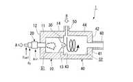
- FIG. 1 is a cross-sectional view of an exhaust gas treatment apparatus according to a first embodiment to which the present invention is applied.
- the exhaust gas treatment apparatus 1 of the present embodiment includes a first combustion furnace 10, a first burner 20, a throttle unit 30, a second combustion furnace 40, and an inlet (second ) And an exhaust port 60 are schematically configured.
- the exhaust gas treatment method of the present embodiment to be described later can be implemented.
- the first combustion furnace 10 treats the first exhaust gas A discharged from the carbonization furnace and the graphitization furnace, and the second combustion furnace 40 discharges the second exhaust gas from the flameproofing furnace.
- the exhaust gas B can be treated.
- the first combustion furnace 10 has a cylindrical shape (for example, a cylindrical shape) for burning and decomposing harmful gases such as hydrogen cyanide and ammonia contained in the first exhaust gas A by burning the first exhaust gas A. It is a furnace.
- the first combustion furnace 10 has a closed portion 12 and an inner peripheral wall 14, and has a first internal space S1 in which one end is closed and the other end is opened.
- the material of the first combustion furnace 10 is not particularly limited. Specifically, for example, an alumina refractory, an alumina-silica refractory, or the like can be used.
- the first combustion furnace 10 is provided with a first burner 20, a first thermometer (not shown), and a throttle unit 30.
- the first burner 20 is provided so as to penetrate the center of the blocking portion 12.
- the first burner 20 is provided so as to be coaxial with the first combustion furnace 10. Accordingly, the first burner 20 can form a flame in the first internal space S1, and the first gas in the first internal space S1 can be burned by the flame.
- the first burner 20 is supplied with fuel and a combustion-supporting gas. By adjusting the flow rates of the fuel and the combustion-supporting gas, a combustion amount and an oxygen ratio described later can be controlled. By controlling the oxygen ratio, a reducing atmosphere flame can be formed.
- gas fuels such as city gas and LPG
- liquid fuels such as kerosene and A heavy oil.
- the combustion-supporting gas is not particularly limited as long as it contains oxygen, but a gas having an oxygen concentration of 20.8 (air) to 100% by volume (pure oxygen) is preferably used. From the viewpoint of improving the decomposition rate, it is particularly preferable to use a gas having an oxygen concentration of 25 to 100% by volume.
- a gas having a high oxygen concentration By using a gas having a high oxygen concentration, the temperature in the combustion furnace can be increased, and the decomposition rate can be increased. As a result, the exhaust gas residence time in the first internal space S1 is shortened, so that the first combustion furnace 10 can be made smaller.
- the combustion amount of the first burner 20 (based on the temperature in the first combustion furnace 10 and the temperature in the second combustion furnace 40 ( A control unit (not shown) for controlling (described later) is provided.
- the first burner 20 is provided with a first exhaust gas A supply path (not shown).
- a supply port (not shown) for the first exhaust gas A is provided at the tip of the first burner 20 that opens into the first internal space S1 in the first combustion furnace 10. Accordingly, the first burner 20 can form a reducing atmosphere flame in the first internal space S1 and supply the first exhaust gas A into the first internal space S1.
- the throttle portion 30 is provided on the opening 13 side of the inner peripheral wall 14.
- the aperture area of the opening 13 can be regulated by the diaphragm 30. By restricting the opening area, it is possible to prevent gas (including oxygen) in the second internal space S2 described later from entering the first internal space S1. As a result, the inside of the first internal space S1 can be maintained in a reducing atmosphere.
- the second combustion furnace 40 is provided on the secondary side of the first combustion furnace 10.
- the second combustion furnace 40 has a cylindrical shape (for example, a cylindrical shape) for burning and decomposing harmful gases such as hydrogen cyanide and ammonia contained in the second exhaust gas B by burning the second exhaust gas B. It is a furnace.
- the second combustion furnace 40 has a closed portion 42 and an inner peripheral wall 44, and has a second internal space S2 in which one end is closed and the other end is opened.
- the material of the second combustion furnace 40 is not particularly limited. Specifically, for example, an alumina refractory, an alumina-silica refractory, or the like can be used.
- the opening 13 of the first combustion furnace 10 and the opening 43 of the second combustion furnace 40 are joined in a state of facing each other, and the first internal space S1. And the second internal space S2.
- the third exhaust gas after burning the first exhaust gas A can be supplied from the first internal space S1 to the second internal space S2.
- the exhaust gas after the first exhaust gas is burned in the first combustion furnace 10 is defined as “third exhaust gas”.
- the second exhaust gas B can be burned using the sensible heat and latent heat of the third exhaust gas.
- harmful gases such as hydrogen cyanide contained in the second exhaust gas B can be combusted and decomposed.
- the second combustion furnace 40 is provided with a blowing port (second blowing port) 50 and an exhaust port 60.
- the blowing port (second blowing port) 50 is provided on the opening 43 side of the inner peripheral wall 44 of the second combustion furnace 40.
- the second exhaust gas B can be supplied from the inlet 50 to the second internal space S2.
- the blowing port 50 is provided so that the second exhaust gas B can be blown in the tangential direction of the inner peripheral wall 44.
- a swirl flow can be formed by the third exhaust gas and the second exhaust gas B in the second internal space S2, so that the harmful gas contained in the second exhaust gas B can be efficiently decomposed by combustion. can do.
- the exhaust port 60 is provided so as to penetrate the closed portion 42 of the second combustion furnace 40.
- the gas burned in the second internal space S2 can be discharged from the exhaust port 60 to the outside.
- the exhaust gas treatment method of the present embodiment is an exhaust gas treatment method in which the first exhaust gas A is processed by the first combustion process, and the second exhaust gas B is processed by the second combustion process.
- the first combustion step is a step of burning the first exhaust gas A at a low oxygen ratio with an oxygen ratio of 0.8 or less.
- first exhaust gas A the gas discharged from the carbonization process and the graphitization process
- the supplied first exhaust gas A is burned by the first burner 20 in a temperature range of 1000 to 1600 ° C.
- the temperature in the first combustion furnace 10 is measured by a first thermometer (not shown), and the temperature in the second combustion furnace 40 is measured by a second thermometer (not shown). Yes.
- the combustion temperature of the first burner 20 is controlled by a control unit (not shown) to control the combustion temperature.
- the first burner 20 is supplied with fuel gas and combustion-supporting gas, and the amount of combustion is controlled by controlling the supply amount of the fuel gas and combustion-supporting gas.
- the “burning amount” is the amount of heat per unit time generated by burning the fuel. As the amount of combustion increases, the amount of heat generated per unit time increases, so the temperature of the first internal space S1 increases.
- the first exhaust gas A to be processed in the first combustion furnace 10 is a nitrogen-based exhaust gas containing hydrogen cyanide, ammonia and the like at a high concentration, so that the oxygen ratio is higher than the stoichiometric ratio (oxygen ratio 0).
- a large amount of NO x is produced when the combustion treatment is performed at a temperature higher than .8).
- processing is performed while forming a reducing atmosphere under combustion conditions with an oxygen ratio of 0.8 or less. While thereby suppressing the formation of NO x, it is possible to burn decomposition. Therefore, in the exhaust gas treatment method of the present embodiment, the oxygen ratio is controlled by controlling the proportion of oxygen contained in the combustion-supporting gas with respect to the fuel gas.
- oxygen ratio means a value obtained by dividing the amount of oxygen supplied to the burner by the theoretical amount of oxygen required to burn the fuel supplied to the burner. Therefore, theoretically, a state where the oxygen ratio is 1.0 can be said to be a state where oxygen can be completely burned using excess or deficiency.
- the third exhaust gas generated by the combustion is supplied to the second combustion furnace 40 through the opening 13.
- the second combustion step is a step of burning the second exhaust gas B using the sensible heat and latent heat of the exhaust gas discharged in the first combustion step in the second combustion furnace 40.
- the second exhaust gas B is an air-based exhaust gas containing hydrogen cyanide and ammonia, and the amount of emission is much larger than that of the first exhaust gas A.
- the first exhaust gas A when it is attempted to perform combustion decomposition by reducing the oxygen ratio to 0.8 or less, it is necessary to use a large amount of fuel, which is not practical.
- hydrogen cyanide and ammonia can be decomposed while suppressing the production of NO x by performing combustion treatment at a low temperature even in an atmosphere in which oxygen is present. Therefore, in the exhaust gas treatment method of the present embodiment, the second exhaust gas B is burned in the temperature range of 700 to 1200 ° C., thereby decomposing hydrogen cyanide and ammonia while suppressing the generation of NO x .
- the third exhaust gas supplied from the first combustion furnace 10 is mixed with the second exhaust gas B supplied from the inlet 50 provided in the second combustion furnace 40.
- gases such as CO and H 2 contained in the third exhaust gas and contained in the second exhaust gas B Oxygen is combusted, and the temperature in the second combustion furnace 40 can be raised to 700 ° C. or higher by heat generated by the combustion.
- harmful gas such as hydrogen cyanide contained in the second exhaust gas B is combusted and decomposed.
- the sensible heat and latent heat (combustion heat amount of the exhaust gas) of the third exhaust gas discharged in the first combustion process are effectively used.
- the temperature in the second combustion furnace 40 is measured by a second thermometer (not shown). Based on the measured temperature, the control unit (not shown) controls the oxygen ratio of the first burner 20 to control the amount of unburned gas flowing into the second combustion furnace 40. Thereby, the temperature in the second combustion furnace 40 can be controlled.
- exhaust gas generated by combustion in the second internal space S2 is discharged to the outside from the exhaust port 60, whereby the exhaust gas treatment method of the present embodiment is completed.
- the first combustion furnace 10 for treating the first exhaust gas A the first burner 20 provided in the first combustion furnace, A second combustion furnace 40 for treating the second exhaust gas B, the second combustion furnace 40 being provided on the secondary side of the first combustion furnace 10, and the first combustion furnace 10
- the first internal space S1 and the second internal space S2 of the second combustion furnace 40 are in communication with each other, and the third exhaust gas after burning in the first combustion furnace 10 is used.
- the second combustion furnace 40 can be supplied.
- the 2nd combustion furnace 40 the 2nd exhaust gas B can be processed using the sensible heat and latent heat of a 3rd exhaust gas.
- the amount of fuel used to process the first and second exhaust gases A and B can be reduced.
- the equipment cost and the maintenance cost can be reduced.
- the exhaust gas treatment apparatus 1 of the present embodiment since it is configured to include the throttle portion 30 for regulating the opening area between the first internal space S1 and the second internal space S2, The gas (including oxygen) in the second internal space S2 can be prevented from entering the first internal space S1, and the inside of the first internal space S1 can be maintained in a reducing atmosphere.
- the first exhaust gas A is configured to burn at a low oxygen ratio with an oxygen ratio of 0.8 or less, the generation of NO x is suppressed.
- the first exhaust gas A can be treated.
- the second combustion includes a first combustion process for treating the first exhaust gas A and a second combustion process for treating the second exhaust gas B.
- the second exhaust gas B is burned using the sensible heat and latent heat of the exhaust gas discharged in the first combustion process, so that the amount of burner fuel used can be reduced. it can.
- the equipment cost and the maintenance cost can be reduced.
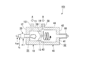
- FIG. 2 is a cross-sectional view of an exhaust gas treatment apparatus according to a second embodiment to which the present invention is applied.
- the exhaust gas treatment apparatus 101 of the present embodiment includes a first combustion furnace 10, a first burner 20, a throttle unit 30, a second combustion furnace 40, and an inlet (second ) 50, an exhaust port 60, and a blow port (first blow port) 151. That is, the exhaust gas treatment apparatus 101 of the present embodiment is configured differently from the above-described exhaust gas treatment apparatus 1 in that it includes the inlet 151. For this reason, the same components as those in the exhaust gas treatment device 1 are denoted by the same reference numerals and description thereof is omitted.
- the blowing port (first blowing port) 151 is provided on the closed part 12 side of the inner peripheral wall 14 of the first combustion furnace 10. Through the inlet 151, the first exhaust gas A can be supplied to the first internal space S1.
- the inlet 151 can be provided so that the first exhaust gas A can be blown in the tangential direction of the inner peripheral wall 14. Thereby, since the swirl
- the configuration includes the inlet 151, and the first exhaust gas A can be supplied from the inner peripheral wall 14 of the first combustion furnace 10. Thereby, the first exhaust gas A directly near the flame that is present in the oxygen does not enter, it is possible to further suppress the formation of NO x.
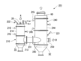
- FIG. 3 is a figure which shows the structure of the waste gas processing apparatus which is 3rd Embodiment to which this invention is applied.
- the exhaust gas treatment apparatus 201 of the present embodiment includes a first combustion furnace 210, a first burner 20, a second combustion furnace 240, and an inlet (second inlet) 250. And an exhaust port 60, a second burner 221, and a connecting pipe 231.
- the exhaust gas treatment apparatus 201 of the present embodiment includes a second burner 221, further includes a connecting pipe 231 between the first combustion furnace 210 and the second combustion furnace 240, and the first
- the configuration differs from the above-described exhaust gas treatment apparatus 1 in that the combustion furnace 210 and the second combustion furnace 240 are configured as separate furnace bodies. For this reason, the same components as those in the exhaust gas treatment device 1 are denoted by the same reference numerals and description thereof is omitted.
- the first combustion furnace 210 is a furnace for burning and decomposing harmful gases such as hydrogen cyanide and ammonia contained in the first exhaust gas A by burning the first exhaust gas A.
- the shape of the first combustion furnace 210 is a cylindrical shape (for example, a cylindrical shape) closed at both ends.
- the first combustion furnace 210 has a first internal space S1 inside.
- an opening 213 is provided on the lower bottom side of the inner peripheral wall of the first combustion furnace 210.
- the material of the first combustion furnace 210 is not particularly limited. Specifically, for example, an alumina refractory, an alumina-silica refractory, or the like can be used.
- the first thermometer 215 is provided on the inner peripheral wall 214.
- the temperature in the first combustion furnace 210 can be measured by the first thermometer 215.
- the amount of combustion of the first burner 20 can be controlled by a control unit (not shown).
- the connecting pipe 231 is a pipe provided for communicating the first internal space S1 in the first combustion furnace 210 and the second internal space S2 in the second combustion furnace 240 described later. . Specifically, the connecting pipe 231 is provided so as to connect the opening 213 of the first combustion furnace 210 and the opening 243 of the second combustion furnace 240 described later.
- the material of the connecting pipe 231 is not particularly limited, and specifically, for example, an alumina refractory, an alumina-silica refractory, or the like can be used.
- the gas (including oxygen) in the second internal space S2 enters the first internal space S1. Can be prevented. As a result, the inside of the first internal space S1 can be maintained in a reducing atmosphere.
- the second combustion furnace 240 is a furnace for burning and decomposing harmful gases such as hydrogen cyanide and ammonia contained in the second exhaust gas B by burning the second exhaust gas B.
- the second combustion furnace 240 is provided on the secondary side of the first combustion furnace 210 via the connecting pipe 231.
- the shape of the second combustion furnace 240 is a cylindrical shape (for example, a cylindrical shape) closed at both ends.
- the second combustion furnace 240 has a second internal space S2 inside.
- an opening 243 is provided on the lower bottom side of the inner peripheral wall of the second combustion furnace 240.
- the material of the second combustion furnace 240 is not particularly limited. Specifically, for example, an alumina refractory, an alumina-silica refractory, or the like can be used.
- the second burner 221 is provided on the inlet 250 side of the inner peripheral wall 244 of the second combustion furnace 240.
- combustion of the second exhaust gas B and the third exhaust gas can be performed stably.
- the second burner 221 is supplied with fuel and a combustion-supporting gas. By adjusting the flow rates of the fuel and the combustion-supporting gas, the combustion amount and the oxygen ratio described later can be controlled.
- the fuel and the combustion-supporting gas those similar to the first burner 20 can be used.
- the second burner 221 may not always be burned, and may be ignited when the temperature in the second combustion furnace 240 becomes a predetermined temperature or lower.
- the blowing port (second blowing port) 250 is provided on the opposite side of the opening 243 of the second combustion furnace 240. From the inlet 250, the 2nd waste gas B can be supplied to 2nd internal space S2. The blowing port 250 can be provided so that the second exhaust gas B can be blown in the tangential direction of the inner peripheral wall 244. Thereby, since the swirl flow by the second exhaust gas B can be formed in the second internal space S2, the mixing with the third exhaust gas is promoted, and the harmful gas contained in the second exhaust gas B Can be efficiently decomposed by combustion.
- the second thermometer 245 is provided on the inner peripheral wall 244.
- the temperature in the second combustion furnace 240 can be measured by the second thermometer 245.
- the combustion amount and oxygen ratio of the second burner 221 can be controlled by a control unit (not shown).
- the exhaust gas treatment apparatus 201 of the present embodiment since the second burner 221 is provided, the combustion of the second exhaust gas B and the third exhaust gas can be performed stably.
- the connecting pipe 231 is provided between the first combustion furnace 210 and the second combustion furnace 240, and the first combustion furnace 210 and the second combustion furnace 240 are provided. Since the combustion furnace 240 and the combustion furnace 240 are configured as separate furnace bodies, the length of the furnace can be adjusted, and when installed vertically, the height can be lowered and the degree of freedom of installation can be increased. it can.
- the example which joined two combustion furnaces was demonstrated in the exhaust gas processing apparatus 1,101,201 of embodiment mentioned above, even if it is an aspect which divides
- the throttle unit 30 is provided inside the combustion furnace, the primary side space of the throttle unit 30 is a first combustion furnace, and the secondary side space is a second combustion furnace.
- the primary side space of the inlet (second inlet) 50 is used as the first combustion furnace, and the secondary side space is used as the second combustion. Use a furnace.
- the throttle part 30 was provided in the opening part 13 side of the 1st combustion furnace 10 in the exhaust gas processing apparatus 1 and 101 of embodiment mentioned above, the throttle part 30 was 2nd combustion furnace. It may be provided on the opening 43 side of the inner peripheral wall 44 of 40.
- a second burner may be provided.
- combustion of the second exhaust gas B and the third exhaust gas can be performed stably.
- Example 1 Comparative with direct combustion method
- Table 1 shows the composition and flow rate of the simulated gas of the first exhaust gas and the second exhaust gas. NO was used for the simulated gas as an alternative to HCN (the validity of using NO as the simulated gas will be described later).
- the simulation gas was subjected to three conditions (conditions 1-1, 1-2, and 1-3).
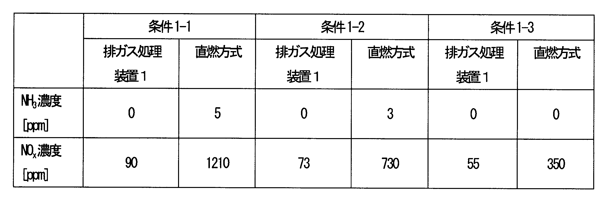
- Table 2 shows the combustion conditions of the burner of the exhaust gas treatment apparatus 1 of this embodiment and the direct combustion type exhaust gas treatment apparatus.
- the first burner 20 was burned at an oxygen ratio of 0.7 using pure oxygen having an oxygen concentration of 100% as the combustion-supporting gas.
- the temperature of the combustion furnace was 1600 ° C. for the first combustion furnace 10 and 1000 ° C. for the second combustion furnace 40. Further, in a direct combustion processing apparatus, the processing was performed at 1000 ° C.
- Table 3 shows the test results. From this result, in the exhaust gas treatment apparatus 1 of this embodiment, ammonia (NH 3 ) can be decomposed to an extremely low concentration even under the condition 1-1 in which NO and NH 3 are added at the highest concentration, and NO x It was confirmed that the production of can be suppressed to about 90 ppm. On the other hand, in the exhaust gas treatment apparatus of the direct combustion system, it was confirmed that the NO x concentration increases when NO and NH 3 are decomposed. Moreover, in the exhaust gas processing apparatus 1 of this embodiment, it confirmed that the 1st exhaust gas and the 2nd exhaust gas could be processed with less fuel compared with a direct combustion system.
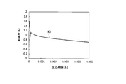
- Example 2 (Effect of oxygen ratio) Using the same exhaust gas treatment apparatus 1 as in Example 1, the oxygen ratio of the first burner 20 was changed as shown in Table 4, and the first exhaust gas and the second exhaust gas shown in Condition 1-2 in Table 3 were changed. The concentration of NH 3 and NO x contained in the exhaust gas after treating the simulated gas was confirmed.
- FIG. 4 shows the relationship between the concentration of NH 3 and NO x in the exhaust gas after treatment discharged from the exhaust port 60 of the exhaust gas treatment apparatus 1 and the oxygen ratio. From this result, it was confirmed that NH 3 is 0.1 ppm or less under all conditions, and that almost all can be decomposed. Further, when the oxygen ratio of the first burner 20 is larger than 0.8, NO x tends to increase rapidly, and by making the oxygen ratio 0.8 or less, while suppressing generation of NO x , It was confirmed that the first exhaust gas can be treated.
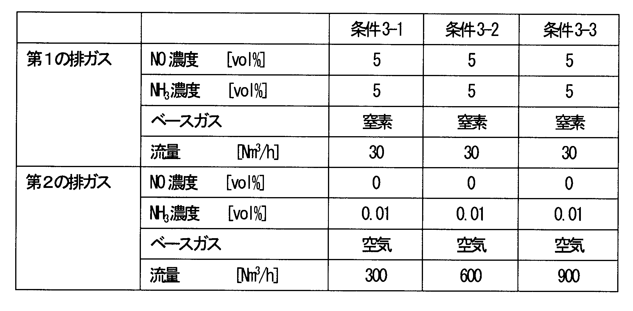
- Example 3> (Pilot equipment test) The exhaust gas treatment apparatus 201 of this embodiment shown in FIG. 3 was used to perform exhaust gas treatment with pilot equipment.
- Table 5 shows the composition and flow rate of the simulated gas of the first exhaust gas and the second exhaust gas.
- the second exhaust gas was flowed under three conditions of 300, 600, and 900 Nm 3 / h (conditions 3-1, 3-2, and 3-3).
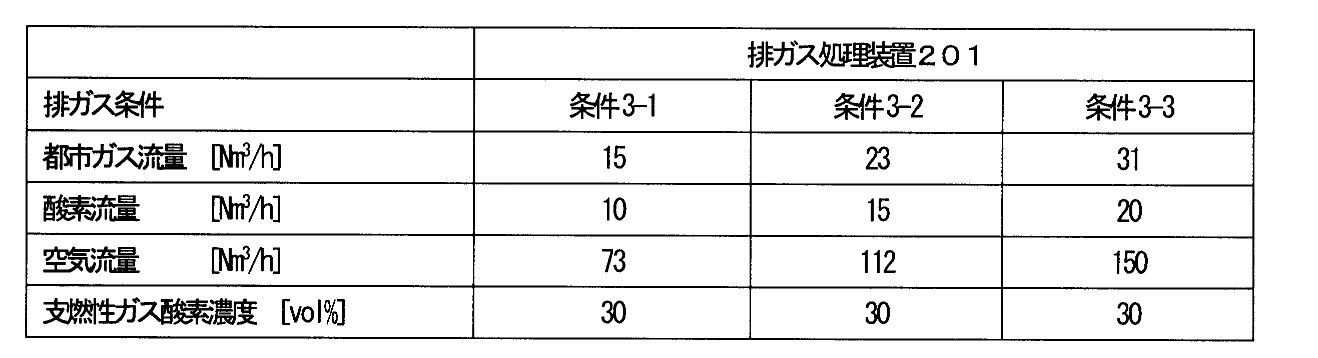
- Table 6 shows the burner combustion conditions under the above exhaust gas conditions.
- Table 7 shows the concentration of NH 3 and NO x in the exhaust gas after treatment discharged from the exhaust port 60 of the exhaust gas treatment device 201. From this result, it was confirmed that in the exhaust gas treatment apparatus 201 of the present embodiment, NH 3 can be decomposed to an extremely low concentration, and further, generation of NO x accompanying combustion can be suppressed.
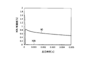
- Example 4> (Validity verification of simulated gas) NO was used as an alternative simulation gas for HCN. The validity of using NO for the simulated gas was examined by reaction analysis by simulation. Reaction analysis was performed using CHEMKIN-PRO (manufactured by Reaction Design, detailed chemical reaction analysis support software). Table 8 shows the analysis conditions. Condition 4-1 shows the case where HCN is added to the first combustion furnace 10 in a reducing combustion atmosphere, and condition 4-2 shows the case where NO is added.
- FIG. 5 shows the decomposition behavior of HCN and the generation / decomposition behavior of NO by reaction analysis under condition 4-1.
- FIG. 6 shows the NO decomposition behavior when NO is added according to the reaction analysis under Condition 4-2. From FIG. 5, it can be seen that HCN is rapidly decomposed in a reducing combustion atmosphere, and NO X is rapidly generated and then gradually decomposed. Comparing the NO concentration changes in FIG. 5 and FIG. 6, the decomposition behavior shows the same tendency, and by using NO as a simulation gas, the decomposition behavior of NO generated along with the decomposition of HCN can be evaluated. .
- the exhaust gas treatment method and exhaust gas treatment apparatus of the present invention can be applied to an apparatus and method for treating exhaust gas containing hydrogen cyanide, ammonia and the like.
Landscapes
- Engineering & Computer Science (AREA)
- Mechanical Engineering (AREA)
- General Engineering & Computer Science (AREA)
- Environmental & Geological Engineering (AREA)
- Chemical & Material Sciences (AREA)
- Manufacturing & Machinery (AREA)
- Chemical Kinetics & Catalysis (AREA)
- General Chemical & Material Sciences (AREA)
- Textile Engineering (AREA)
- Combustion & Propulsion (AREA)
- Incineration Of Waste (AREA)
Abstract
Description
本願は、2015年1月21日に、日本に出願された特願2015-009572号に基づき優先権を主張し、その内容をここに援用する。
(1)繊維状物質を不活性ガス雰囲気中で炭素化する炭素化炉及び黒鉛化する黒鉛化炉から排出される第1の排ガスを処理する第1の燃焼工程と、空気雰囲気中で耐炎化する耐炎化炉から排出される第2の排ガスを処理する第2の燃焼工程と、を含む排ガス処理方法であって、前記第1の燃焼工程において、前記第1の排ガスを酸素比が0.8以下の低酸素比で燃焼し、前記第2の燃焼工程において、前記第1の燃焼工程により排出された第3の排ガスの顕熱と潜熱とを利用して、前記第2の排ガスを燃焼することを特徴とする排ガス処理方法。
(排ガス処理装置)
先ず、本発明を適用した第1の実施形態である排ガス処理装置1について説明する。図1は、本発明を適用した第1の実施形態である排ガス処理装置の断面図である。
図1に示すように、本実施形態の排ガス処理装置1は、第1の燃焼炉10と、第1のバーナ20と、絞り部30と、第2の燃焼炉40と、吹込口(第2の吹込口)50と、排気口60と、を備えて概略構成されている。
次に、上述した排ガス処理装置1を用いた本実施形態の排ガス処理方法を説明する。
本実施形態の排ガス処理方法は、第1の排ガスAを第1の燃焼工程により処理し、第2の排ガスBを第2の燃焼工程により処理する排ガス処理方法である。
これによりNOxの生成を抑制しながら、燃焼分解することが可能となる。そのため、本実施形態の排ガス処理方法では、燃料ガスに対して支燃性ガスに含まれる酸素の割合を制御することで、酸素比を制御している。
ところで、第2の排ガスBは、シアン化水素、アンモニアを含有する空気ベースの排ガスであり、第1の排ガスAに比較して排出量が非常に多い。そのため、第1の排ガスAと同じように酸素比を0.8以下に下げて燃焼分解しようとした場合、大量の燃料を使用する必要があり、現実的でない。また、シアン化水素、アンモニアは、酸素が存在する雰囲気においても、低い温度で燃焼処理することにより、NOxの生成を抑えながら分解することができる。
そこで、本実施形態の排ガス処理方法では、第2の排ガスBを700~1200℃の温度範囲で燃焼することにより、NOxの生成を抑えながら、シアン化水素、アンモニアを分解する。
次に、本発明を適用した第2の実施形態である排ガス処理装置について説明する。図2は、本発明を適用した第2の実施形態である排ガス処理装置の断面図である。
図2に示すように、本実施形態の排ガス処理装置101は、第1の燃焼炉10と、第1のバーナ20と、絞り部30と、第2の燃焼炉40と、吹込口(第2の吹込口)50と、排気口60と、吹込口(第1の吹込口)151と、を備えて概略構成されている。すなわち、本実施形態の排ガス処理装置101は、吹込口151を備える点において、上述した排ガス処理装置1と異なる構成となっている。そのため、排ガス処理装置1と同一の構成については同一の符号を付すとともに、説明を省略する。
次に、図3は、本発明を適用した第3の実施形態である排ガス処理装置の構成を示す図である。
図3に示すように、本実施形態の排ガス処理装置201は、第1の燃焼炉210と、第1のバーナ20と、第2の燃焼炉240と、吹込口(第2の吹込口)250と、排気口60と、第2のバーナ221と、連結管231と、を備えて概略構成されている。本実施形態の排ガス処理装置201は、第2のバーナ221を備えており、さらに第1の燃焼炉210と第2の燃焼炉240との間に連結管231を設けており、かつ第1の燃焼炉210と第2の燃焼炉240とが別々の炉体で構成されている点において、上述した排ガス処理装置1と異なる構成となっている。そのため、排ガス処理装置1と同一の構成については同一の符号を付すとともに、説明を省略する。
(直燃方式との比較)
図1に示す本実施形態の排ガス処理装置1、及び従来技術である直燃方式の排ガス処理装置を用いて、炭素化炉および黒鉛化炉から排出される第1の排ガス、及び耐炎化炉から排出される第2の排ガスの模擬ガスを用いて処理試験を行った。
表2に本実施形態の排ガス処理装置1と直燃方式の排ガス処理装置のバーナの燃焼条件を示す。
なお、本実施例では、第1のバーナ20では、支燃性ガスとして酸素濃度100%の純酸素を用い、酸素比0.7で燃焼させた。燃焼炉の温度は、第1の燃焼炉10が1600℃、第2の燃焼炉40が1000℃であった。
また、直燃方式の処理装置では、1000℃で処理を行った。


また、本実施形態の排ガス処理装置1では、直燃方式に比べて少ない燃料で、第1の排ガス及び第2の排ガスを処理することができることを確認した。
(酸素比の影響)
実施例1と同じ排ガス処理装置1を用いて、表4に示すように第1のバーナ20の酸素比を変えて、表3の条件1-2に示す第1の排ガス及び第2の排ガスの模擬ガスを処理した後の排ガスに含まれる、NH3、NOxの濃度を確認した。

本結果から、NH3は、全ての条件で0.1ppm以下であり、ほぼ全て分解することができることを確認した。
また、第1のバーナ20の酸素比を0.8より大きくすると、NOxが急激に増加する傾向にあり、酸素比を0.8以下にすることにより、NOxの生成を抑制しながら、第1の排ガスを処理することができることを確認した。
(パイロット設備での試験)
図3に示す本実施形態の排ガス処理装置201を用いて、パイロット設備で排ガス処理を行った。
表5に第1の排ガスと第2の排ガスの模擬ガスの組成と流量を示す。第2の排ガスの流量は、300、600、900Nm3/hの3条件で実施した(条件3-1、3-2、3-3)。また、表6に上記各排ガス条件におけるバーナ燃焼条件を示す。

(模擬ガスの妥当性検証について)
HCNの代替の模擬ガスとしてNOを用いた。模擬ガスにNOを用いることの妥当性をシミュレーションによる反応解析により検討した。
反応解析は、CHEMKIN-PRO(Reaction Design社製、詳細化学反応解析支援ソフトウェア)を用いて行った。解析条件を表8に示す。条件4-1は、還元燃焼雰囲気下の第1の燃焼炉10にHCNを添加した場合を示し、条件4-2は、NOを添加した場合を示す。
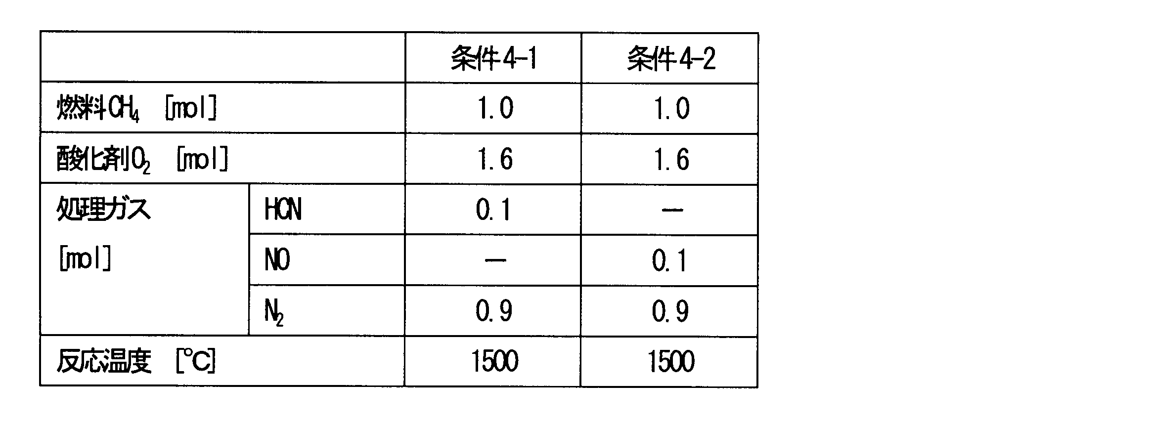
図5から、還元燃焼雰囲気下においてHCNは急激に分解され、それに伴いNOXが急激に生成された後、徐々に分解されることを示していることがわかる。図5と図6のNOの濃度変化を比較すると、分解挙動は同様の傾向を示しており、NOを模擬ガスとして用いることにより、HCNの分解に伴って生成されるNOの分解挙動を評価できる。
10、210 第1の燃焼炉
11 炉壁
12 閉塞部
13、213 開口部
14、214 内周壁
20 第1のバーナ
30 絞り部
40、240 第2の燃焼炉
41 炉壁
42 閉塞部
43、243 開口部
44、244 内周壁
50、250 吹込口(第2の吹込口)
60 排気口
151 吹込口(第1の吹込口)
215 第1の温度計
221 第2のバーナ
222 パイロットバーナ
231 連結管
245 第2の温度計
S1 第1の内部空間
S2 第2の内部空間
A 第1の排ガス
B 第2の排ガス
Claims (14)
- 繊維状物質を不活性ガス雰囲気中で炭素化する炭素化炉及び黒鉛化する黒鉛化炉から排出される第1の排ガスを処理する第1の燃焼工程と、空気雰囲気中で耐炎化する耐炎化炉から排出される第2の排ガスを処理する第2の燃焼工程と、を含む排ガス処理方法であって、
前記第1の燃焼工程において、前記第1の排ガスを酸素比が0.8以下の低酸素比で燃焼し、
前記第2の燃焼工程において、前記第1の燃焼工程により排出された第3の排ガスの顕熱と潜熱とを利用して、前記第2の排ガスを燃焼することを特徴とする排ガス処理方法。 - 前記第1の燃焼工程において、1000~1600℃で前記第1の排ガスを燃焼し、
前記第2の燃焼工程において、700~1200℃で前記第2の排ガスを燃焼することを特徴とする請求項1に記載の排ガス処理方法。 - 第1の排ガスを処理する第1の燃焼炉と、
第2の排ガスを処理する第2の燃焼炉と、
前記第1の燃焼炉内に前記第1の排ガスを供給する第1の排ガス供給手段と、
前記第2の燃焼炉内に前記第2の排ガスを供給する第2の排ガス供給手段と、
前記第1の燃焼炉に設けられた第1のバーナと、を備え、
前記第1の燃焼炉の二次側に前記第2の燃焼炉が設けられているとともに、
前記第1の燃焼炉の内部空間と、前記第2の燃焼炉の内部空間とが、連通されていることを特徴とする排ガス処理装置。 - 前記第1の燃焼炉及び前記第2の燃焼炉は、それぞれ開口部を有しており、前記開口部同士が互いに対向した状態で接合されていることを特徴とする請求項3に記載の排ガス処理装置。
- 前記第1の燃焼炉及び前記第2の燃焼炉の少なくともいずれか一方が、前記開口部の開口面積を規制する絞り部を有することを特徴とする請求項4に記載の排ガス処理装置。
- 前記第1の燃焼炉と前記第2の燃焼炉との間に設けられ、当該第1の燃焼炉の内部空間と当該第2の燃焼炉の内部空間とを連通させる連通管をさらに備えることを特徴とする請求項3に記載の排ガス処理装置。
- 前記第2の燃焼炉に設けられた第2のバーナをさらに備えることを特徴とする請求項3乃至6のいずれか一項に記載の排ガス処理装置。
- 前記第1の燃焼炉内の温度を測定する第1の温度計と、
前記第2の燃焼炉内の温度を測定する第2の温度計と、
前記第1のバーナの燃焼量を制御する制御部と、をさらに備え、
前記第1の温度計及び前記第2の温度計から得た温度に基づいて前記第1のバーナの燃焼量を制御することを特徴とする請求項3乃至6のいずれか一項に記載の排ガス処理装置。 - 前記第1の燃焼炉内の温度を測定する第1の温度計と、
前記第2の燃焼炉内の温度を測定する第2の温度計と、
前記第1のバーナ及び前記第2のバーナの燃焼量を制御する制御部と、をさらに備え、
前記第1の温度計及び前記第2の温度計から得た温度に基づいて前記第1のバーナ及び前記第2のバーナの燃焼量を制御することを特徴とする請求項7に記載の排ガス処理装置。 - 前記第1の燃焼炉に設けられている前記第1のバーナの支燃性ガスとして、酸素濃度が25~100体積%の酸素富化空気を用いることを特徴とする請求項3乃至9のいずれか一項に記載の排ガス処理装置。
- 前記第1の排ガス供給手段が前記第1のバーナであり、前記第1の排ガスを前記第1のバーナから供給することを特徴とする請求項3乃至10のいずれか一項に記載の排ガス処理装置。
- 前記第1の排ガス供給手段が、前記第1の燃焼炉の炉壁に設けられた第1の吹込口であり、前記第1の排ガスを前記第1の吹込口から供給することを特徴とする請求項3乃至10のいずれか一項に記載の排ガス処理装置。
- 前記第2の排ガス供給手段が、前記第2の燃焼炉の炉壁に設けられた第2の吹込口であり、前記第2の吹込口は、前記第2の排ガスを前記第2の燃焼炉の内周壁の接線方向から吹き込むことができるように設けられていることを特徴とする請求項3乃至12のいずれか一項に記載の排ガス処理装置。
- 前記排ガス処理装置の後段に熱交換器をさらに備え、前記第2の燃焼炉から排出される排ガスの顕熱を利用して前記第2の排ガスを予熱することを特徴とする請求項3乃至13のいずれか一項に記載の排ガス処理装置。
Priority Applications (5)
| Application Number | Priority Date | Filing Date | Title |
|---|---|---|---|
| ES15878856T ES2742896T3 (es) | 2015-01-21 | 2015-09-10 | Método de tratamiento de gases de escape y dispositivo de tratamiento de gases de escape |
| EP15878856.2A EP3249295B1 (en) | 2015-01-21 | 2015-09-10 | Exhaust gas treatment method and exhaust gas treatment device |
| KR1020177018623A KR101973957B1 (ko) | 2015-01-21 | 2015-09-10 | 배기 가스 처리 방법 및 배기 가스 처리 장치 |
| US15/541,757 US10502417B2 (en) | 2015-01-21 | 2015-09-10 | Exhaust gas treatment method and exhaust gas treatment device |
| CN201580070682.6A CN107110500B (zh) | 2015-01-21 | 2015-09-10 | 废气处理方法及废气处理装置 |
Applications Claiming Priority (2)
| Application Number | Priority Date | Filing Date | Title |
|---|---|---|---|
| JP2015009572A JP6307769B2 (ja) | 2015-01-21 | 2015-01-21 | 排ガス処理方法及び排ガス処理装置 |
| JP2015-009572 | 2015-01-21 |
Publications (1)
| Publication Number | Publication Date |
|---|---|
| WO2016117167A1 true WO2016117167A1 (ja) | 2016-07-28 |
Family
ID=56416730
Family Applications (1)
| Application Number | Title | Priority Date | Filing Date |
|---|---|---|---|
| PCT/JP2015/075754 WO2016117167A1 (ja) | 2015-01-21 | 2015-09-10 | 排ガス処理方法及び排ガス処理装置 |
Country Status (8)
| Country | Link |
|---|---|
| US (1) | US10502417B2 (ja) |
| EP (1) | EP3249295B1 (ja) |
| JP (1) | JP6307769B2 (ja) |
| KR (1) | KR101973957B1 (ja) |
| CN (1) | CN107110500B (ja) |
| ES (1) | ES2742896T3 (ja) |
| TW (1) | TWI675170B (ja) |
| WO (1) | WO2016117167A1 (ja) |
Cited By (2)
| Publication number | Priority date | Publication date | Assignee | Title |
|---|---|---|---|---|
| WO2018230055A1 (ja) * | 2017-06-13 | 2018-12-20 | 東レ株式会社 | 炭素繊維の製造方法 |
| WO2022061473A1 (en) * | 2020-09-25 | 2022-03-31 | Industrial Ceramics Limited | Device for enhancing reaction kinetics for incineration process |
Families Citing this family (5)
| Publication number | Priority date | Publication date | Assignee | Title |
|---|---|---|---|---|
| JP6491147B2 (ja) * | 2016-07-20 | 2019-03-27 | 大陽日酸株式会社 | 排ガス処理方法、排ガス処理装置及び炭素繊維製造システム |
| CN108261902B (zh) * | 2017-01-04 | 2023-12-01 | 恩国环保科技(上海)有限公司 | 一种炭化炉尾气处理装置及处理方法 |
| CN108240631A (zh) * | 2018-01-03 | 2018-07-03 | 上海煜工环保科技有限公司 | 一种含VOCs的废氮气高温焚毁处置系统及方法 |
| CN108800168A (zh) * | 2018-06-26 | 2018-11-13 | 宜兴市智博环境设备有限公司 | 一种三段式有机氮废液焚烧装置及焚烧工艺 |
| CN113719843B (zh) * | 2021-08-12 | 2022-09-09 | 中国矿业大学 | 一种低浓度瓦斯资源再利用的方法 |
Citations (11)
| Publication number | Priority date | Publication date | Assignee | Title |
|---|---|---|---|---|
| JPS5385975A (en) * | 1977-01-07 | 1978-07-28 | Continental Carbon Co | Method and apparatus for combustion of industrial waste gases |
| JPS58164922A (ja) * | 1982-03-11 | 1983-09-29 | シエル・インタ−ナシヨネイル・リサ−チ・マ−チヤツピイ・ベ−・ウイ | アンモニア−含有廃ガスの燃焼方法および装置 |
| JPH06184831A (ja) * | 1992-12-15 | 1994-07-05 | Tonen Corp | 炭素繊維の製造方法 |
| JP2001355820A (ja) * | 2000-06-12 | 2001-12-26 | Sumitomo Seika Chem Co Ltd | 排ガスの処理方法および処理装置 |
| JP2003130326A (ja) * | 2001-10-26 | 2003-05-08 | Mitsubishi Heavy Ind Ltd | ガス燃焼処理方法およびその装置 |
| JP3106971U (ja) * | 2004-08-02 | 2005-01-27 | ロザイ工業株式会社 | 直接燃焼式脱臭装置 |
| JP2007093156A (ja) * | 2005-09-30 | 2007-04-12 | Nikko Kinzoku Kk | 排ガスの処理方法 |
| JP2012067977A (ja) * | 2010-09-24 | 2012-04-05 | Mitsubishi Rayon Co Ltd | 焼成炉の排ガス燃焼装置 |
| JP2012067419A (ja) * | 2010-09-24 | 2012-04-05 | Mitsubishi Rayon Co Ltd | 炭素化炉用排ガス処理装置 |
| JP2013032608A (ja) * | 2011-06-29 | 2013-02-14 | Toray Ind Inc | 排ガス処理方法 |
| JP2014528052A (ja) * | 2011-09-09 | 2014-10-23 | ダイカー コンバスチョン エンジニアーズ ビー.ヴイ.Duiker Combustion Engineers B.V. | Nh3を焼却する方法及びnh3焼却炉 |
Family Cites Families (12)
| Publication number | Priority date | Publication date | Assignee | Title |
|---|---|---|---|---|
| US4519993A (en) | 1982-02-16 | 1985-05-28 | Mcgill Incorporated | Process of conversion for disposal of chemically bound nitrogen in industrial waste gas streams |
| JPS58164922U (ja) * | 1982-04-30 | 1983-11-02 | ダイキヨ−・ベバスト株式会社 | 乗物の天井窓装置 |
| JP3106971B2 (ja) | 1996-08-21 | 2000-11-06 | トヨタ自動車株式会社 | 酸素センサ |
| JP2000111025A (ja) * | 1998-09-30 | 2000-04-18 | Hosokawa Micron Corp | 二次燃焼炉 |
| JP2001324119A (ja) | 2000-05-12 | 2001-11-22 | Mitsubishi Rayon Co Ltd | 炭素化炉用排ガス処理装置および炭素化炉からの排ガス処理方法 |
| JP4247701B2 (ja) * | 2001-07-13 | 2009-04-02 | カシオ計算機株式会社 | 動画記録装置及び動画記録方法 |
| JP3892263B2 (ja) | 2001-10-01 | 2007-03-14 | 三菱レイヨン株式会社 | 耐炎化炉、及び耐炎化炉の温度制御方法 |
| US7799297B2 (en) | 2003-07-10 | 2010-09-21 | Taiheiyo Cement Corporation | Device and method for processing combustion exhaust gas |
| US7273366B1 (en) | 2003-10-28 | 2007-09-25 | Soil-Therm Equipment, Inc. | Method and apparatus for destruction of vapors and waste streams |
| US7845166B2 (en) * | 2007-09-27 | 2010-12-07 | Tenneco Automotive Operating Company Inc. | Exhaust system with plural emission treatment devices |
| JP5097564B2 (ja) | 2008-01-23 | 2012-12-12 | 三菱レイヨン株式会社 | 炭素繊維製造装置 |
| JP5492482B2 (ja) | 2009-07-14 | 2014-05-14 | 株式会社桂精機製作所 | 直接燃焼式脱臭炉 |
-
2015
- 2015-01-21 JP JP2015009572A patent/JP6307769B2/ja active Active
- 2015-09-10 ES ES15878856T patent/ES2742896T3/es active Active
- 2015-09-10 US US15/541,757 patent/US10502417B2/en not_active Expired - Fee Related
- 2015-09-10 KR KR1020177018623A patent/KR101973957B1/ko active IP Right Grant
- 2015-09-10 WO PCT/JP2015/075754 patent/WO2016117167A1/ja active Application Filing
- 2015-09-10 EP EP15878856.2A patent/EP3249295B1/en active Active
- 2015-09-10 CN CN201580070682.6A patent/CN107110500B/zh not_active Expired - Fee Related
- 2015-09-17 TW TW104130775A patent/TWI675170B/zh active
Patent Citations (11)
| Publication number | Priority date | Publication date | Assignee | Title |
|---|---|---|---|---|
| JPS5385975A (en) * | 1977-01-07 | 1978-07-28 | Continental Carbon Co | Method and apparatus for combustion of industrial waste gases |
| JPS58164922A (ja) * | 1982-03-11 | 1983-09-29 | シエル・インタ−ナシヨネイル・リサ−チ・マ−チヤツピイ・ベ−・ウイ | アンモニア−含有廃ガスの燃焼方法および装置 |
| JPH06184831A (ja) * | 1992-12-15 | 1994-07-05 | Tonen Corp | 炭素繊維の製造方法 |
| JP2001355820A (ja) * | 2000-06-12 | 2001-12-26 | Sumitomo Seika Chem Co Ltd | 排ガスの処理方法および処理装置 |
| JP2003130326A (ja) * | 2001-10-26 | 2003-05-08 | Mitsubishi Heavy Ind Ltd | ガス燃焼処理方法およびその装置 |
| JP3106971U (ja) * | 2004-08-02 | 2005-01-27 | ロザイ工業株式会社 | 直接燃焼式脱臭装置 |
| JP2007093156A (ja) * | 2005-09-30 | 2007-04-12 | Nikko Kinzoku Kk | 排ガスの処理方法 |
| JP2012067977A (ja) * | 2010-09-24 | 2012-04-05 | Mitsubishi Rayon Co Ltd | 焼成炉の排ガス燃焼装置 |
| JP2012067419A (ja) * | 2010-09-24 | 2012-04-05 | Mitsubishi Rayon Co Ltd | 炭素化炉用排ガス処理装置 |
| JP2013032608A (ja) * | 2011-06-29 | 2013-02-14 | Toray Ind Inc | 排ガス処理方法 |
| JP2014528052A (ja) * | 2011-09-09 | 2014-10-23 | ダイカー コンバスチョン エンジニアーズ ビー.ヴイ.Duiker Combustion Engineers B.V. | Nh3を焼却する方法及びnh3焼却炉 |
Cited By (6)
| Publication number | Priority date | Publication date | Assignee | Title |
|---|---|---|---|---|
| WO2018230055A1 (ja) * | 2017-06-13 | 2018-12-20 | 東レ株式会社 | 炭素繊維の製造方法 |
| CN110709542A (zh) * | 2017-06-13 | 2020-01-17 | 东丽株式会社 | 碳纤维的制造方法 |
| KR20200016214A (ko) * | 2017-06-13 | 2020-02-14 | 도레이 카부시키가이샤 | 탄소섬유의 제조 방법 |
| US11261545B2 (en) | 2017-06-13 | 2022-03-01 | Toray Industries, Inc. | Carbon fiber production method |
| KR102507504B1 (ko) | 2017-06-13 | 2023-03-08 | 도레이 카부시키가이샤 | 탄소섬유의 제조 방법 |
| WO2022061473A1 (en) * | 2020-09-25 | 2022-03-31 | Industrial Ceramics Limited | Device for enhancing reaction kinetics for incineration process |
Also Published As
| Publication number | Publication date |
|---|---|
| KR101973957B1 (ko) | 2019-04-30 |
| US20170370580A1 (en) | 2017-12-28 |
| CN107110500A (zh) | 2017-08-29 |
| JP2016133286A (ja) | 2016-07-25 |
| KR20170093904A (ko) | 2017-08-16 |
| EP3249295B1 (en) | 2019-08-07 |
| ES2742896T3 (es) | 2020-02-17 |
| JP6307769B2 (ja) | 2018-04-11 |
| CN107110500B (zh) | 2019-07-12 |
| EP3249295A1 (en) | 2017-11-29 |
| EP3249295A4 (en) | 2018-08-22 |
| TW201627607A (zh) | 2016-08-01 |
| TWI675170B (zh) | 2019-10-21 |
| US10502417B2 (en) | 2019-12-10 |
Similar Documents
| Publication | Publication Date | Title |
|---|---|---|
| WO2016117167A1 (ja) | 排ガス処理方法及び排ガス処理装置 | |
| KR100827869B1 (ko) | 연료공급장치 및 연료공급방법 | |
| JP3665542B2 (ja) | Nox低減のための燃料希釈方法および装置 | |
| JP2020112280A (ja) | アンモニアを混焼できるボイラ装置及び火力発電設備 | |
| JP2022015464A (ja) | アンモニア燃料燃焼装置 | |
| US20120129111A1 (en) | Premix for non-gaseous fuel delivery | |
| KR20160003670A (ko) | 방사 버너 | |
| Teng et al. | Control of NOx emissions through combustion modifications for reheating furnaces in steel plants | |
| JP5635285B2 (ja) | ガラス溶解炉およびガラス溶解炉における排ガスの処理方法 | |
| CN109477636B (zh) | 废气处理方法、废气处理装置及碳纤维制造系统 | |
| US9004910B2 (en) | Method for combustion of a low-grade fuel | |
| JP4876621B2 (ja) | 炭素繊維製造時の排ガス処理方法 | |
| WO2018230055A1 (ja) | 炭素繊維の製造方法 | |
| JP7387243B2 (ja) | アンモニア燃料燃焼装置 | |
| KR840000354B1 (ko) | 저 NOx 연소 방법 | |
| JP2024004304A (ja) | 浸炭用ガス発生装置、及び浸炭用ガス生成方法 | |
| Kim et al. | Investigation of Fuel Lean Reburning |
Legal Events
| Date | Code | Title | Description |
|---|---|---|---|
| 121 | Ep: the epo has been informed by wipo that ep was designated in this application |
Ref document number: 15878856 Country of ref document: EP Kind code of ref document: A1 |
|
| REEP | Request for entry into the european phase |
Ref document number: 2015878856 Country of ref document: EP |
|
| ENP | Entry into the national phase |
Ref document number: 20177018623 Country of ref document: KR Kind code of ref document: A |
|
| WWE | Wipo information: entry into national phase |
Ref document number: 15541757 Country of ref document: US |
|
| NENP | Non-entry into the national phase |
Ref country code: DE |