WO2016116997A1 - 放電ランプ点灯装置及び放電ランプ点灯方法 - Google Patents
放電ランプ点灯装置及び放電ランプ点灯方法 Download PDFInfo
- Publication number
- WO2016116997A1 WO2016116997A1 PCT/JP2015/006501 JP2015006501W WO2016116997A1 WO 2016116997 A1 WO2016116997 A1 WO 2016116997A1 JP 2015006501 W JP2015006501 W JP 2015006501W WO 2016116997 A1 WO2016116997 A1 WO 2016116997A1
- Authority
- WO
- WIPO (PCT)
- Prior art keywords
- discharge lamp
- control
- lighting
- arc
- voltage
- Prior art date
- Legal status (The legal status is an assumption and is not a legal conclusion. Google has not performed a legal analysis and makes no representation as to the accuracy of the status listed.)
- Ceased
Links
Images





Classifications
-
- H—ELECTRICITY
- H05—ELECTRIC TECHNIQUES NOT OTHERWISE PROVIDED FOR
- H05B—ELECTRIC HEATING; ELECTRIC LIGHT SOURCES NOT OTHERWISE PROVIDED FOR; CIRCUIT ARRANGEMENTS FOR ELECTRIC LIGHT SOURCES, IN GENERAL
- H05B41/00—Circuit arrangements or apparatus for igniting or operating discharge lamps
- H05B41/14—Circuit arrangements
- H05B41/26—Circuit arrangements in which the lamp is fed by power derived from DC by means of a converter, e.g. by high-voltage DC
- H05B41/28—Circuit arrangements in which the lamp is fed by power derived from DC by means of a converter, e.g. by high-voltage DC using static converters
- H05B41/288—Circuit arrangements in which the lamp is fed by power derived from DC by means of a converter, e.g. by high-voltage DC using static converters with semiconductor devices and specially adapted for lamps without preheating electrodes, e.g. for high-intensity discharge lamps, high-pressure mercury or sodium lamps or low-pressure sodium lamps
-
- Y—GENERAL TAGGING OF NEW TECHNOLOGICAL DEVELOPMENTS; GENERAL TAGGING OF CROSS-SECTIONAL TECHNOLOGIES SPANNING OVER SEVERAL SECTIONS OF THE IPC; TECHNICAL SUBJECTS COVERED BY FORMER USPC CROSS-REFERENCE ART COLLECTIONS [XRACs] AND DIGESTS
- Y02—TECHNOLOGIES OR APPLICATIONS FOR MITIGATION OR ADAPTATION AGAINST CLIMATE CHANGE
- Y02B—CLIMATE CHANGE MITIGATION TECHNOLOGIES RELATED TO BUILDINGS, e.g. HOUSING, HOUSE APPLIANCES OR RELATED END-USER APPLICATIONS
- Y02B20/00—Energy efficient lighting technologies, e.g. halogen lamps or gas discharge lamps
Definitions
- the present invention relates to a discharge lamp lighting device and a discharge lamp lighting method for lighting a discharge lamp.
- the arc discharge of the discharge lamp can be unstable by reducing the lamp power in order to dimm the image darkly or being affected by the convection of the sealed gas in the lamp.
- the discharge lamp may extinguish (extinguish) in some cases. This is called lamp non-lighting.
- Patent Document 1 Japanese Patent Laid-Open No. 2012-160387.
- This technology utilizes the phenomenon that when the arc discharge becomes unstable during constant power control, the lamp voltage rises and the lamp current decreases, and when the lamp voltage exceeds a predetermined upper limit value, It is determined that a side jump arc has occurred, and the constant power control is switched to the constant current control. Thereby, the fall of an electric current is suppressed and non-lighting is prevented.
- the present invention provides a discharge lamp lighting device and a discharge lamp lighting method capable of preventing lamp non-lighting and quickly returning to a steady lighting state even when arc discharge becomes unstable. The challenge is to do.
- an aspect of a discharge lamp lighting device includes a lighting circuit that supplies electric energy to a discharge lamp, and a deformation phenomenon detector that detects a deformation phenomenon of an arc that may occur in the discharge lamp. And a control unit that controls the lighting circuit by switching between constant power control using the power of the discharge lamp as a predetermined power command value and constant current control using the current of the discharge lamp as a predetermined current command value; The control unit controls constant power control of the lighting circuit when the arc deformation phenomenon is not detected by the deformation phenomenon detection unit during steady lighting, and the deformation phenomenon detection unit deforms the arc.
- the lighting circuit When a phenomenon is detected, the lighting circuit is configured to perform constant current control, and the control responsiveness at the time of control switching between the constant power control and the constant current control is higher than the control responsiveness before and after the control switching. Do It provided the answer of changing section.
- the lighting circuit control is switched from the constant power control to the constant current control. Therefore, even when the lamp voltage rises due to the deformation of the arc, the decrease in the lamp current can be suppressed, the arc can be maintained, and the discharge lamp can be prevented from being unlit.
- control responsiveness at the time of control switching is made higher than the control responsiveness before and after the control switching, so that the system fluctuation at the time of control switching can be stabilized. Therefore, it is possible to quickly return to the steady lighting state.
- the control unit performs the constant power control and the constant current control by PID control
- the responsiveness changing unit includes at least a PID value that is a control parameter of the PID control.
- the control responsiveness may be changed by changing one.
- the deformation phenomenon detection unit includes the voltage detection unit.
- the non-lighting prevention control can be activated at an appropriate timing, and it is possible to quickly return to the steady lighting state.
- an aspect of the discharge lamp lighting device includes a lighting circuit that supplies electric energy to the discharge lamp, a voltage detection unit that detects the voltage of the discharge lamp, and a determination unit that determines the state of the discharge lamp.
- a lighting circuit that supplies electric energy to the discharge lamp
- a voltage detection unit that detects the voltage of the discharge lamp
- a determination unit that determines the state of the discharge lamp.
- a control unit that controls a lighting circuit, and the control unit performs constant power control on the lighting circuit when a deformation phenomenon of the arc is not detected by the deformation phenomenon detection unit during steady lighting, and Upon detection of the deformation behavior of the arc in the form phenomenon detecting unit, the lighting circuit being configured to constant current control.
- the lighting circuit control is switched from constant power control to constant current control. Therefore, even when the lamp voltage rises due to the deformation of the arc, the decrease in the lamp current can be suppressed, the arc can be maintained, and the discharge lamp can be prevented from being unlit. Further, when detecting the arc deformation phenomenon, the threshold voltage is changed according to the lighting condition of the discharge lamp, so that highly accurate detection is possible. Therefore, the non-lighting prevention control can be activated at an appropriate timing, and it is possible to quickly return to the steady lighting state.
- the determination unit may determine at least one of the power command value, the temperature of the discharge lamp, and the degree of wear of the discharge lamp as the state of the discharge lamp. .
- the threshold voltage Set considering that the voltage at the time of lamp lighting varies depending on the lighting condition such as the power command value, which is the set power at the time of constant power control, the temperature of the discharge lamp, and the degree of wear of the discharge lamp, the threshold voltage Set. Therefore, it is possible to appropriately detect the arc deformation phenomenon.
- the threshold voltage may be set larger as the power command value is larger.
- the threshold voltage is set in consideration of the fact that the voltage when the lamp is lit increases as the power command value increases. Therefore, the deformation phenomenon of the arc can be detected with high accuracy.
- the threshold voltage may be set to be larger as the temperature of the discharge lamp is higher.
- the threshold voltage is set in consideration of the fact that the voltage when the lamp is lit increases as the temperature of the discharge lamp increases. Therefore, the deformation phenomenon of the arc can be detected with high accuracy.
- the threshold voltage may be set larger as the degree of wear of the discharge lamp is higher.
- the threshold voltage is set in consideration of the fact that the voltage when the lamp is lit increases as the degree of wear of the discharge lamp increases. Therefore, the deformation phenomenon of the arc can be detected with high accuracy.
- the lighting circuit control is switched from the constant power control to the constant current control. Therefore, even when the lamp voltage rises due to the deformation of the arc, the decrease in the lamp current can be suppressed, the arc can be maintained, and the discharge lamp can be prevented from being unlit. Further, in this non-lighting prevention control, the control responsiveness at the time of control switching is made higher than the control responsiveness before and after the control switching, so that the system fluctuation at the time of control switching can be stabilized. Therefore, it is possible to quickly return to the steady lighting state.
- one aspect of a discharge lamp lighting method is a discharge lamp lighting method for supplying electric energy to a discharge lamp and lighting the discharge lamp, the step of detecting a voltage of the discharge lamp, The step of determining the state of the discharge lamp, and when the detected voltage of the discharge lamp exceeds a threshold voltage set based on the determined state of the discharge lamp, an arc deformation phenomenon has occurred in the discharge lamp.
- a constant power control using the lighting circuit as a predetermined power command value when the arc deformation phenomenon that may occur in the discharge lamp is not detected during steady lighting.
- the lighting circuit is controlled by constant current control using a current of the discharge lamp as a predetermined current command value.
- the lighting circuit control is switched from constant power control to constant current control. Therefore, even when the lamp voltage rises due to the deformation of the arc, the decrease in the lamp current can be suppressed, the arc can be maintained, and the discharge lamp can be prevented from being unlit. Further, when detecting the arc deformation phenomenon, the threshold voltage is changed according to the lighting condition of the discharge lamp, so that highly accurate detection is possible. Therefore, the non-lighting prevention control can be activated at an appropriate timing, and it is possible to quickly return to the steady lighting state.
- FIG. 1 is a diagram illustrating a configuration example of a discharge lamp lighting device according to the present embodiment.
- FIG. 2 is an example of a bridge circuit constituting the inverter circuit unit.
- FIG. 3 is a configuration diagram illustrating an example of a discharge lamp.
- FIG. 4 is a diagram illustrating the relationship between the power command value and the lamp voltage during stable lighting.
- FIG. 5 is a diagram illustrating changes in lamp voltage and lamp current during lighting.
- FIG. 6 is a diagram showing the relationship between the total lighting time of the discharge lamp and the lamp voltage.
- FIG. 7 is a diagram for explaining a threshold voltage setting method.
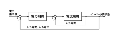
- FIG. 8 is an example of cascade control.
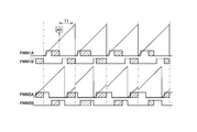
- FIG. 9 is a diagram illustrating the operation timing of the SW element during phase modulation control.
- FIG. 9 is a diagram illustrating the operation timing of the SW element during phase modulation control.
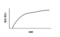
- FIG. 10 is a diagram illustrating a control response characteristic of a delay system.
- FIG. 11 is a diagram illustrating a general control response characteristic.
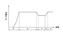
- FIG. 12 is a process transition diagram of the lamp.
- FIG. 13 is a diagram for explaining a change in the lighting condition of the lamp.
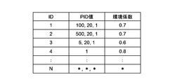
- FIG. 14 is a memory map example of PID values.
- FIG. 1 is a diagram illustrating a configuration example of a discharge lamp lighting device according to the present embodiment.
- the discharge lamp lighting device 10 includes a lighting circuit 30 connected to a commercial AC power source 20 and a control unit 40 that controls the lighting circuit 30, and supplies power to the discharge lamp 50 as a load. By supplying, the discharge lamp 50 is turned on.
- the discharge lamp lighting device 10 can be used as a light source for a digital projector in a movie theater, for example.
- the lighting circuit 30 includes an input circuit unit 31, a step-up / step-down circuit unit 32, an inverter circuit unit 33, and a rectifier circuit unit 34.
- the input circuit unit 31 includes a circuit breaker, an EMI (Electromagnetic Interference) filter (noise filter), an inrush prevention circuit, and the like, and is connected to the commercial AC power supply 20.
- the step-up / down circuit unit 32 includes a rectifier, a capacitor, a chopper coil, a switching element, a switching element drive circuit, an input voltage detection circuit, an output voltage detection circuit, and the like.
- the step-up / step-down circuit unit 32 converts the AC voltage of the AC power supply 20 into a DC voltage by a rectifier, and then boosts and lowers the voltage with a so-called chopper circuit using an inductance.
- the inverter circuit unit 33 includes a bridge circuit including a switching element, a switching driver circuit, a resonance capacitor, an insulating transformer, and the like, and converts a DC power source into a high frequency AC power source.
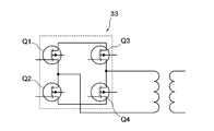
- the bridge circuit is a full bridge circuit including switching elements Q1 to Q4 as shown in FIG. 2, for example.
- the rectifier circuit unit 34 includes a rectifier diode, a ripple suppression coil, a snubber circuit, and the like, and converts the high-frequency AC power converted by the inverter circuit unit 33 into a DC voltage.
- the control unit 40 performs constant power control or constant current control on the lighting circuit 30, and includes a control circuit unit 41, a multiplication circuit unit 42, an A / D conversion unit 43, an IF unit 44, and a time counting unit 45. And a timer unit 46.
- the control circuit unit 41 is mainly composed of a digital control element composed of a CPU and a DSP, and other peripheral elements, and controls the switching driver circuits of the step-up / step-down circuit unit 32 and the inverter circuit unit 33.
- a phase shift type synchronous rectification method is adopted for the control.
- the A / D converter 43 receives the lamp voltage V, the lamp current I, and the lamp voltage W, and converts these input analog signals into, for example, a 12-bit digital signal.
- the IF unit 44 is a circuit capable of communicating with an external device, and inputs / outputs information to / from the external device. For example, the IF unit 44 inputs a lamp lighting signal (start signal) for starting the discharge lamp 50, a lamp extinguishing signal for extinguishing the discharge lamp 50, and the like from an external device.
- the IF unit 44 includes a digital I / O, a communication circuit, and the like.
- the time measuring unit 45 generates a reference signal for controlling the ON time and OFF time of the pulse signal used in the phase modulation control performed by the control circuit unit 41, and outputs this to the control circuit unit 41.
- the timer unit 46 measures the total lighting time of the discharge lamp 50, the time after the discharge lamp 50 is turned off, the time after the discharge lamp 50 is turned on, and the like, and stores the measured time and the control circuit. Output to the unit 41.
- the external storage medium 47 stores various data used in the control by the control circuit unit 41, and is configured by, for example, an EEPROM (Electrically Erasable Programmable Read-Only Memory).
- the discharge lamp 50 is, for example, a short arc type xenon discharge lamp. As shown in FIG. 3, the discharge lamp 50 includes an elliptical arc tube 51 made of quartz glass or the like. Cylindrical electrode support portions 52a and 52b extending outwardly along the tube axis are connected to both ends of the arc tube 51. In addition, sealing tubes 53a and 53b having outer diameters larger than those of the electrode support portions 52a and 52b are connected to the outer ends of the electrode support portions 52a and 52b.
- a discharge space is formed inside the arc tube 51, and a luminescent gas containing xenon (Xe) gas is sealed therein.
- a pair of electrodes (anode 54a and cathode 54b) facing each other are arranged. These electrodes 54a and 54b are made of a refractory metal such as tungsten.
- An electrode rod 55a extending outward from the anode 54a along the tube axis is led out from the end of the sealing tube 53a.
- the electrode rod 55a is sealed (rod sealed) at the end of the sealing tube 53a by means such as a step glass.
- the electrode rod 55b extending outward from the cathode 54b along the tube axis is led out from the end of the sealing tube 53b.
- the electrode rod 55b is sealed (rod sealed) at the end portion of the sealing tube 53b by means such as stepped glass.
- the discharge lamp lighting device 10 When the dielectric breakdown occurs, the discharge lamp lighting device 10 causes an inrush current to flow to the discharge lamp 50 and shifts to arc discharge through glow discharge. Thereafter, the discharge lamp lighting device 10 performs control (constant current control) so as to stably maintain the arc discharge. Thereby, steady lighting is achieved. After the arc discharge is stabilized, the discharge lamp lighting device 10 performs control (constant power control) so that the lamp power becomes constant.
- the control unit 40 performs steady lighting control of the discharge lamp 50 and performs non-lighting prevention control for preventing the discharge lamp 50 from being unlit.
- the non-lighting of the discharge lamp 50 can occur when arc discharge becomes unstable during constant power control and an arc deformation phenomenon occurs (a jumping arc occurs).
- the discharge lamp 50 is lit at rated power by constant power control.
- an arc is maintained between the anode 54a and the cathode 54b by the self magnetic field and current generated along with the discharge current.
- the voltage and current are reduced at the same time, and the self magnetic field is also reduced. Then, the force for maintaining the arc formed between the electrodes is weakened, the arc becomes unstable, and a side jump arc can be generated.
- the discharge lamp 50 is often lit in a horizontal posture in the projector in practice. Therefore, xenon gas, which is an issuance gas, convects in the arc tube 51 due to heat generated while the discharge lamp 50 is turned on. At this time, an upward stress acts on the arc due to the convective xenon gas, and a deformation phenomenon (side jump arc) in which the arc is bent upward or the starting point of the arc is displaced upward may occur. Furthermore, there is an application in which the discharge lamp 50 is lit while being changed not only in a horizontal posture but also in a vertical posture. In such a case, the arc may become unstable as the posture of the discharge lamp 50 changes.
- the non-lighting prevention control is control for switching from constant power control to constant current control when a side jump arc is detected during constant power control.
- the lamp current set value in the constant current control is the lamp current value at the time of stable lighting.
- a lamp voltage upper limit value (threshold voltage) corresponding to the lighting condition of the discharge lamp 50 is set, and the lateral voltage is exceeded when the lamp voltage exceeds the threshold voltage. It is determined that a jump arc has occurred (deformation phenomenon detection unit). Specifically, information such as the power command value, the temperature of the discharge lamp 50 (cathode 54b), the degree of wear of the discharge lamp 50 (cathode 54b) is acquired as the lighting status of the discharge lamp 50, and the threshold value is based on these information. Set the voltage.
- the power command value is designated by the user from the outside, and is acquired by the IF unit 44.
- the cathode 50 of the discharge lamp 50 includes a main body portion made of tungsten (W) and a tip end portion made of triated tungsten in which tungsten (W) contains thorium oxide (ThO 2 ).
- W tungsten
- ThO 2 thorium oxide
- the temperature of the cathode 54b of the discharge lamp 50 varies with a predetermined temperature characteristic. Therefore, the temperature of the discharge lamp 50 is determined based on the time after the discharge lamp 50 measured by the timer unit 46 is turned off and the time after the discharge lamp 50 is turned on.
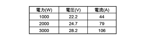
- FIG. 4 is a diagram illustrating the relationship between the power command value and the lamp voltage during stable lighting. As shown in FIG. 4, the lamp voltage during stable lighting increases as the set power supplied to the discharge lamp 50 increases.
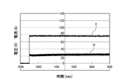
- FIG. 5 is a diagram illustrating changes in lamp voltage and lamp current during lighting. In FIG. 5, the horizontal axis represents the time since the discharge lamp 50 was turned on, and the vertical axis represents the lamp voltage V and the lamp current I. As shown in FIG.
- the lamp voltage V increases by about several volts in response to a rise in lamp temperature from the start of lighting until stable lighting, in other words, until the lamp is sufficiently warmed from the cold state. Then, for example, about 300 seconds from the start of lighting, the lamp voltage V stabilizes and becomes a substantially constant value.
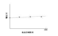
- FIG. 6 is a diagram showing the relationship between the total lighting time of the discharge lamp 50 and the lamp voltage.
- the horizontal axis represents the total lighting time of the discharge lamp 50
- the vertical axis represents the lamp voltage V.
- the lamp voltage V increases during stable lighting as the total lighting time increases. Specifically, the lamp voltage increases by 3V to 5V at the end of life (total lighting time of about 300 hours) with respect to the initial lighting.
- FIG. 7 is a diagram for explaining a threshold voltage setting method used for detecting the occurrence of a side-jump arc.
- the horizontal axis X is the lamp input power (power command value)
- the vertical axis Y is the threshold voltage.
- the slope A is a coefficient related to the time from lighting, and is set to a larger value as the time from lighting is longer (the lamp temperature is higher).
- the lamp voltage is substantially constant regardless of the time from lighting, so after the time from lighting reaches a certain time (for example, 300 seconds). It may be a fixed value.
- the offset B is a coefficient related to the total lighting time, and is set to a larger value as the total lighting time is longer (as the degree of lamp wear is higher).
- the threshold voltage is set to a larger value as the lamp input power is larger, and it is difficult to determine that a side jump arc is generated even at the same lamp voltage. Furthermore, the threshold voltage is set to a larger value as the time from lighting is longer (the lamp temperature is higher) and the total lighting time is longer (the lamp is more worn). It becomes difficult to be judged that has occurred.
- the inclination A and the offset B are stored in a table in the external storage medium 47, for example. The table is created and stored in advance by a method of performing experiments using a plurality of lamps of the same type and obtaining an average value.
- a detection voltage value low-pass filter for suppressing the voltage oscillation may be mounted, and the threshold voltage may be calculated in consideration of a coefficient C related to this filter. .
- the threshold voltage for detecting the occurrence of a jumping arc is corrected according to the lamp lighting condition. Therefore, it is possible to improve the detection accuracy of the occurrence of a side jump arc.
- the threshold voltage is set to a fixed value, the threshold voltage is excessively increased in order to prevent erroneous detection. In this case, the detection accuracy of the occurrence of a side jump arc is lowered, and switching from constant power control to constant current control cannot be performed at an appropriate timing.
- the control responsiveness is changed in accordance with the lighting condition of the lamp (change in current voltage).
- FIG. 9 is a diagram illustrating operation timings of the switching elements Q1 to Q4 during general phase modulation control.
- Current control is pulse-by-pulse control, and as shown in FIG. 9, the current deviation is obtained from the result of A / D conversion, and the next conduction angle is obtained by interruption calculation.
- a period T1 from A / D conversion to the next conduction angle control is a short period of, for example, several ⁇ sec.
- the current control requires high-speed control in order to minimize the fluctuation of the arc current.
- power control that is an outer loop controls the lamp power to be constant with respect to a power command value designated by the user from the outside.
- the outer loop may be slow control in order to suppress system turbulence.
- the load fluctuation of the lamp becomes large and the lamp may be extinguished. Therefore, as shown in FIG. It is common to set a delay system compared to control.
- the control responsiveness is lowered in this way, it is not possible to deal with a transient phenomenon during lighting such as a jumping arc.
- a transient phenomenon such as a jumping arc.
- the system is disturbed when switching from constant current control by non-lighting prevention control to constant power control, and in some cases, excessive power control may occur.
- the excessive power is a state in which the same current is flowing as in the constant current control although the voltage is high.
- the lighting state of the lamp becomes an initial lighting state through an initialization state (S1) and a standby state (S2) after power-on. In the initial lighting state, constant current control is performed both before lighting (S3) and after lighting (S4).
- the lighting state of the lamp transitions to a steady lighting state.
- the steady lighting state when no side-jump arc generation is detected (S5), constant power control is performed.
- the non-lighting prevention control is activated (S7). That is, switching from constant power control to constant current control.
- the lighting state of the lamp changes from S3 ⁇ S4 ⁇ S5 ⁇ S6 ⁇ S7 ⁇ S5
- the lighting state of the lamp changes as shown in FIG.
- the lighting state of the lamp is [a] during initial lighting ⁇ [b] during constant power control ⁇ [c] during control switching from constant power control to constant current control ⁇ [d] during constant current control ⁇ [e] During the control switching from the constant current control to the constant power control, a transition is made from [b] During constant power control. That is, the lighting state of the lamp is any one of [a] to [e].
- the PID value (proportional coefficient, integral coefficient, differential coefficient), which is a control parameter for PID control, is changed to realize control responsiveness according to the lighting condition of the lamp.
- Responsiveness change unit Specifically, as shown in FIG. 14, a plurality of PID values are stored in advance in an external storage medium (EEPROM) 47. Then, the control unit 40 selects a PID value corresponding to the lighting state of the lamp from a plurality of PID values stored in the external storage medium 47, and performs PID control using the selected PID value.
- the PID value with the slowest response of PID control is selected.
- a PID value is selected which is slightly faster than [a] initial lighting but is relatively slow in response.
- a PID value is selected so that the control responsiveness is almost equivalent to that in [b] constant power control.
- the response of PID control is Select a fast PID value.
- the discharge lamp lighting device 10 changes the responsiveness of the PID control according to the lighting condition of the lamp, it is possible to perform appropriate lamp lighting control.
- the discharge lamp lighting device 10 can cope with system disturbance at the time of control switching by increasing control responsiveness at the time of control switching by the non-lighting prevention control, and can stabilize system fluctuations. Therefore, the discharge lamp lighting device 10 can quickly return to the stable lighting state.
- the discharge lamp lighting device 10 stores a plurality of PID values in a storage medium in advance and reads out an appropriate PID value according to the lighting condition of the lamp and performs control, the control responsiveness is relatively simple. Can be adjusted.
- DESCRIPTION OF SYMBOLS 10 Discharge lamp lighting device, 20 ... AC power supply, 30 ... Lighting circuit, 31 ... Input circuit part, 32 ... Buck-boost circuit part, 33 ... Inverter circuit part, 34 ... Rectifier circuit part, 40 ... Control part, 41 ... Control Circuit part 42... Multiplying circuit part 43... A / D conversion part (ADC circuit part) 44... IF part 45 45 time measuring part 46 .. timer part 47 .. external storage medium 50. ... arc tube, 52a, 52b ... electrode support, 53a, 53b ... sealing tube, 54a ... anode, 54b ... cathode, 55a, 55b ... electrode rod, 56a, 56b ... glass member
Landscapes
- Circuit Arrangements For Discharge Lamps (AREA)
Abstract
アーク放電が不安定になった場合であっても、ランプの不点灯を防止し、迅速に定常点灯状態へ復帰させることができる放電ランプ点灯装置及び放電ランプ点灯方法が開示される。放電ランプ点灯装置は、放電ランプに電気エネルギーを供給する点灯回路と、放電ランプに生じ得るアークの変形現象を検出する変形現象検出部と、定電力制御と定電流制御とを切り替えて点灯回路を制御する制御部と、を備える。制御部は、定常点灯時、アークの変形現象が非検出であるときは点灯回路を定電力制御し、アークの変形現象を検出したとき、点灯回路を定電流制御する。また、制御部は、定電力制御と定電流制御との制御切替時の制御応答性を、制御切替前後の制御応答性と比べて高くする応答性変更部を備える。
Description
本発明は、放電ランプを点灯するための放電ランプ点灯装置及び放電ランプ点灯方法に関する。
映画館において映写機用光源として用いられる放電ランプ点灯装置として、例えば、ショートアーク型キセノン放電ランプを光源として備えた放電ランプ点灯装置がある。この放電ランプ点灯装置では、放電ランプを点灯させる際、先ず点灯用イグナイタを始動して放電ランプの電極間に絶縁破壊を発生させ、突入電流を流す。その後、アーク放電を安定して維持するように定電流制御し、放電が安定したら定電力制御に移行する。このように、定常状態においては、放電ランプは定電力制御により安定点灯される。
ところで、放電ランプのアーク放電は、映像を暗く調光するためにランプ電力を低下させたり、ランプ内の封入ガスの対流の影響を受けたりすることで不安定になり得る。このような所謂「横跳びアーク」が発生すると、場合によっては放電ランプの立ち消え(消灯)が発生してしまう。これをランプの不点灯という。
ところで、放電ランプのアーク放電は、映像を暗く調光するためにランプ電力を低下させたり、ランプ内の封入ガスの対流の影響を受けたりすることで不安定になり得る。このような所謂「横跳びアーク」が発生すると、場合によっては放電ランプの立ち消え(消灯)が発生してしまう。これをランプの不点灯という。
上記のようなランプの不点灯を抑制するためのランプ点灯装置としては、例えば特許文献1(特開2012-160387号公報)に記載の技術がある。この技術は、定電力制御中にアーク放電が不安定になったとき、ランプ電圧が上昇しランプ電流が減少するといった現象が生じることを利用し、ランプ電圧が所定の上限値を超えたとき、横跳びアークが発生していると判断して定電力制御から定電流制御に切り替えるものである。これにより、電流の低下を抑えて不点灯を防止する。
ところで、放電ランプ点灯装置においては、上述したような横跳びアークが発生したとき、迅速にこれを解消し、定常点灯状態(安定点灯)に復帰させる必要がある。しかしながら、上記特許文献1(特開2012-160387号公報)に記載の技術にあっては、ランプの点灯状況によらずに、予め定められた不点灯防止制御を実施しているだけである。そのため、ランプの点灯状況によっては横跳びアークの発生を精度良く検知することができなかったり、制御切替時に系が不安定となったりするおそれがある。
このように、上記特許文献1(特開2012-160387号公報)に記載の技術では、不点灯防止制御の最適化について考慮されていないため、横跳びアークが発生してから定常点灯状態へ復帰するまでに時間がかかるおそれがある。
そこで、本発明は、アーク放電が不安定になった場合であっても、ランプの不点灯を防止し、迅速に定常点灯状態へ復帰させることができる放電ランプ点灯装置及び放電ランプ点灯方法を提供することを課題としている。
このように、上記特許文献1(特開2012-160387号公報)に記載の技術では、不点灯防止制御の最適化について考慮されていないため、横跳びアークが発生してから定常点灯状態へ復帰するまでに時間がかかるおそれがある。
そこで、本発明は、アーク放電が不安定になった場合であっても、ランプの不点灯を防止し、迅速に定常点灯状態へ復帰させることができる放電ランプ点灯装置及び放電ランプ点灯方法を提供することを課題としている。
上記課題を解決するために、本発明に係る放電ランプ点灯装置の一態様は、放電ランプに電気エネルギーを供給する点灯回路と、前記放電ランプに生じ得るアークの変形現象を検出する変形現象検出部と、前記放電ランプの電力を所定の電力指令値とする定電力制御と、前記放電ランプの電流を所定の電流指令値とする定電流制御とを切り替えて、前記点灯回路を制御する制御部と、を備え、前記制御部は、定常点灯時、前記変形現象検出部で前記アークの変形現象が非検出であるとき、前記点灯回路を定電力制御し、前記変形現象検出部で前記アークの変形現象を検出したとき、前記点灯回路を定電流制御するように構成され、前記定電力制御と前記定電流制御との制御切替時の制御応答性を、制御切替前後の制御応答性と比べて高くする応答性変更部を備える。
このように、アークの変形現象を検出した場合には、点灯回路の制御を定電力制御から定電流制御へ切り替える。したがって、アークの変形によりランプ電圧が上昇した場合であってもランプ電流の低下を抑制することができ、アークを維持し、放電ランプの不点灯を防止することができる。また、この不点灯防止制御において、制御切替時の制御応答性を、制御切替前後の制御応答性と比べて高くするので、制御切替時における系変動の安定化を図ることができる。そのため、迅速に定常点灯状態へ復帰させることができる。
このように、アークの変形現象を検出した場合には、点灯回路の制御を定電力制御から定電流制御へ切り替える。したがって、アークの変形によりランプ電圧が上昇した場合であってもランプ電流の低下を抑制することができ、アークを維持し、放電ランプの不点灯を防止することができる。また、この不点灯防止制御において、制御切替時の制御応答性を、制御切替前後の制御応答性と比べて高くするので、制御切替時における系変動の安定化を図ることができる。そのため、迅速に定常点灯状態へ復帰させることができる。
また、上記の放電ランプ点灯装置において、前記制御部は、PID制御により前記定電力制御および前記定電流制御を実行し、前記応答性変更部は、前記PID制御の制御パラメータであるPID値の少なくとも1つを変更することで、前記制御応答性を変更してもよい。このように、PID値を変更するので、比較的簡易に所望の制御応答性を実現することができる。
さらに、上記の放電ランプ点灯装置において、前記放電ランプの電圧を検出する電圧検出部と、前記放電ランプの状態を判定する判定部と、をさらに備え、前記変形現象検出部は、前記電圧検出部で検出した放電ランプの電圧が、前記判定部で判定した放電ランプの状態に基づいて設定される閾値電圧を超えたとき、前記アークの変形現象が生じていると判断してもよい。
このように、アークの変形現象の検出に用いる閾値電圧を、放電ランプの点灯状況に応じて変更するので、アーク放電が不安定となっていることを高精度で検出可能である。したがって、適切なタイミングで不点灯防止制御を作動させることができ、迅速に定常点灯状態へ復帰させることが可能となる。
さらに、上記の放電ランプ点灯装置において、前記放電ランプの電圧を検出する電圧検出部と、前記放電ランプの状態を判定する判定部と、をさらに備え、前記変形現象検出部は、前記電圧検出部で検出した放電ランプの電圧が、前記判定部で判定した放電ランプの状態に基づいて設定される閾値電圧を超えたとき、前記アークの変形現象が生じていると判断してもよい。
このように、アークの変形現象の検出に用いる閾値電圧を、放電ランプの点灯状況に応じて変更するので、アーク放電が不安定となっていることを高精度で検出可能である。したがって、適切なタイミングで不点灯防止制御を作動させることができ、迅速に定常点灯状態へ復帰させることが可能となる。
また、本発明に係る放電ランプ点灯装置の一態様は、放電ランプに電気エネルギーを供給する点灯回路と、前記放電ランプの電圧を検出する電圧検出部と、前記放電ランプの状態を判定する判定部と、前記電圧検出部で検出した前記放電ランプの電圧が、前記判定部で判定した放電ランプの状態に基づいて設定される閾値電圧を超えたとき、前記放電ランプにアークの変形現象が生じていると判断する変形現象検出部と、前記放電ランプの電力を所定の電力指令値とする定電力制御と、前記放電ランプの電流を所定の電流指令値とする定電流制御とを切り替えて、前記点灯回路を制御する制御部と、を備え、前記制御部は、定常点灯時、前記変形現象検出部で前記アークの変形現象が非検出であるとき、前記点灯回路を定電力制御し、前記変形現象検出部で前記アークの変形現象を検出したとき、前記点灯回路を定電流制御するように構成されている。
このように、アークの変形現象を検出した場合には、点灯回路の制御を定電力制御から定電流制御へ切り替える。したがって、アークの変形によりランプ電圧が上昇した場合であってもランプ電流の低下を抑制することができ、アークを維持し、放電ランプの不点灯を防止することができる。また、アークの変形現象の検出に際し、閾値電圧を放電ランプの点灯状況に応じて変更するので、高精度な検出が可能である。したがって、適切なタイミングで不点灯防止制御を作動させることができ、迅速に定常点灯状態へ復帰させることが可能となる。
また、上記の放電ランプ点灯装置において、前記判定部は、前記放電ランプの状態として、前記電力指令値、前記放電ランプの温度、及び前記放電ランプの磨耗度合いの少なくとも1つを判定してもよい。
このように、ランプ点灯時の電圧が、定電力制御時の設定電力である電力指令値や放電ランプの温度、放電ランプの磨耗度合いといった点灯状況に応じて変動することを考慮して、閾値電圧を設定する。したがって、適切にアークの変形現象を検出することができる。
このように、ランプ点灯時の電圧が、定電力制御時の設定電力である電力指令値や放電ランプの温度、放電ランプの磨耗度合いといった点灯状況に応じて変動することを考慮して、閾値電圧を設定する。したがって、適切にアークの変形現象を検出することができる。
さらに、上記の放電ランプ点灯装置において、前記閾値電圧は、前記電力指令値が大きいほど大きく設定してもよい。このように、ランプ点灯時の電圧が、電力指令値が大きいほど大きくなることを考慮して、閾値電圧を設定する。したがって、精度良くアークの変形現象を検出することができる。
また、上記の放電ランプ点灯装置において、前記閾値電圧は、前記放電ランプの温度が高いほど大きく設定してもよい。このように、ランプ点灯時の電圧が、放電ランプの温度が高いほど大きくなることを考慮して、閾値電圧を設定する。したがって、精度良くアークの変形現象を検出することができる。
さらにまた、上記の放電ランプ点灯装置において、前記閾値電圧は、前記放電ランプの磨耗度合いが高いほど大きく設定してもよい。このように、ランプ点灯時の電圧が、放電ランプの磨耗度合いが高いほど大きくなることを考慮して、閾値電圧を設定する。したがって、精度良くアークの変形現象を検出することができる。
また、上記の放電ランプ点灯装置において、前記閾値電圧は、前記放電ランプの温度が高いほど大きく設定してもよい。このように、ランプ点灯時の電圧が、放電ランプの温度が高いほど大きくなることを考慮して、閾値電圧を設定する。したがって、精度良くアークの変形現象を検出することができる。
さらにまた、上記の放電ランプ点灯装置において、前記閾値電圧は、前記放電ランプの磨耗度合いが高いほど大きく設定してもよい。このように、ランプ点灯時の電圧が、放電ランプの磨耗度合いが高いほど大きくなることを考慮して、閾値電圧を設定する。したがって、精度良くアークの変形現象を検出することができる。
また、本発明に係る放電ランプ点灯方法の一態様は、放電ランプに電気エネルギーを供給し、当該放電ランプを点灯する放電ランプ点灯方法であって、定常点灯時、前記放電ランプに生じ得るアークの変形現象が非検出であるとき、前記点灯回路を、前記放電ランプの電力を所定の電力指令値とする定電力制御により制御し、前記アークの変形現象を検出したとき、前記点灯回路を、前記放電ランプの電流を所定の電流指令値とする定電流制御により制御するに際し、前記定電力制御と前記定電流制御との制御切替時の制御応答性を、制御切替前後の制御応答性と比べて高くする。
このように、アークの変形現象を検出した場合には、点灯回路の制御を定電力制御から定電流制御へ切り替える。したがって、アークの変形によりランプ電圧が上昇した場合であってもランプ電流の低下を抑制することができ、アークを維持し、放電ランプの不点灯を防止することができる。また、この不点灯防止制御において、制御切替時の制御応答性を、制御切替前後の制御応答性と比べて高くするので、制御切替時における系変動の安定化を図ることができる。そのため、迅速に定常点灯状態へ復帰させることができる。
このように、アークの変形現象を検出した場合には、点灯回路の制御を定電力制御から定電流制御へ切り替える。したがって、アークの変形によりランプ電圧が上昇した場合であってもランプ電流の低下を抑制することができ、アークを維持し、放電ランプの不点灯を防止することができる。また、この不点灯防止制御において、制御切替時の制御応答性を、制御切替前後の制御応答性と比べて高くするので、制御切替時における系変動の安定化を図ることができる。そのため、迅速に定常点灯状態へ復帰させることができる。
さらに、本発明に係る放電ランプ点灯方法の一態様は、放電ランプに電気エネルギーを供給し、当該放電ランプを点灯する放電ランプ点灯方法であって、前記放電ランプの電圧を検出するステップと、前記放電ランプの状態を判定するステップと、検出した放電ランプの電圧が、判定した放電ランプの状態に基づいて設定される閾値電圧を超えたとき、前記放電ランプにアークの変形現象が生じていると判断するステップと、を含み、定常点灯時、前記放電ランプに生じ得るアークの変形現象が非検出であるとき、前記点灯回路を、前記放電ランプの電力を所定の電力指令値とする定電力制御により制御し、前記アークの変形現象を検出したとき、前記点灯回路を、前記放電ランプの電流を所定の電流指令値とする定電流制御により制御する。
このように、アークの変形現象を検出した場合には、点灯回路の制御を定電力制御から定電流制御へ切り替える。したがって、アークの変形によりランプ電圧が上昇した場合であってもランプ電流の低下を抑制することができ、アークを維持し、放電ランプの不点灯を防止することができる。また、アークの変形現象の検出に際し、閾値電圧を放電ランプの点灯状況に応じて変更するので、高精度な検出が可能である。したがって、適切なタイミングで不点灯防止制御を作動させることができ、迅速に定常点灯状態へ復帰させることが可能となる。
本発明によれば、アーク放電が不安定になった場合であっても、ランプの不点灯を防止し、迅速に定常点灯状態へ復帰させることができる。
上記した本発明の目的、態様及び効果並びに上記されなかった本発明の目的、態様及び効果は、当業者であれば添付図面及び請求の範囲の記載を参照することにより下記の発明を実施するための形態(発明の詳細な説明)から理解できるであろう。
上記した本発明の目的、態様及び効果並びに上記されなかった本発明の目的、態様及び効果は、当業者であれば添付図面及び請求の範囲の記載を参照することにより下記の発明を実施するための形態(発明の詳細な説明)から理解できるであろう。
以下、本発明の実施の形態を図面に基づいて説明する。
(第1の実施形態)
図1は、本実施形態における放電ランプ点灯装置の構成例を示す図である。
この図1に示すように、放電ランプ点灯装置10は、商用交流電源20に接続される点灯回路30と、点灯回路30を制御する制御部40とを備え、負荷としての放電ランプ50に電力を供給することで当該放電ランプ50を点灯する。この放電ランプ点灯装置10は、例えば、映画館においてデジタル映写機用の光源として用いることができる。
点灯回路30は、入力回路部31と、昇降圧回路部32と、インバータ回路部33と、整流回路部34とを備える。
入力回路部31は、遮断器、EMI(Electromagnetic Interference)フィルター(ノイズフィルター)、突入防止回路等により構成され、商用交流電源20に接続される。
昇降圧回路部32は、整流器、コンデンサ、チョッパ用コイル、スイッチング素子、スイッチング素子ドライブ回路、入力電圧検出回路、出力電圧検出回路などから構成される。この昇降圧回路部32は、整流器によって交流電源20の交流電圧を直流電圧に変換した後、インダクタンスを使用した、所謂チョッパ―回路にて、電圧の昇圧及び降圧を行う。
(第1の実施形態)
図1は、本実施形態における放電ランプ点灯装置の構成例を示す図である。
この図1に示すように、放電ランプ点灯装置10は、商用交流電源20に接続される点灯回路30と、点灯回路30を制御する制御部40とを備え、負荷としての放電ランプ50に電力を供給することで当該放電ランプ50を点灯する。この放電ランプ点灯装置10は、例えば、映画館においてデジタル映写機用の光源として用いることができる。
点灯回路30は、入力回路部31と、昇降圧回路部32と、インバータ回路部33と、整流回路部34とを備える。
入力回路部31は、遮断器、EMI(Electromagnetic Interference)フィルター(ノイズフィルター)、突入防止回路等により構成され、商用交流電源20に接続される。
昇降圧回路部32は、整流器、コンデンサ、チョッパ用コイル、スイッチング素子、スイッチング素子ドライブ回路、入力電圧検出回路、出力電圧検出回路などから構成される。この昇降圧回路部32は、整流器によって交流電源20の交流電圧を直流電圧に変換した後、インダクタンスを使用した、所謂チョッパ―回路にて、電圧の昇圧及び降圧を行う。
インバータ回路部33は、スイッチング素子からなるブリッジ回路、スイッチングドライバー回路、共振コンデンサ、絶縁トランス等により構成され、直流電源を高周波交流電源に変換する。上記ブリッジ回路は、例えば図2に示すように、スイッチング素子Q1~Q4からなるフルブリッジ回路である。
整流回路部34は、整流ダイオード、リップル抑制用コイル、スナバー回路等により構成され、インバータ回路部33で変換された高周波交流電源を直流電圧に変換する。
制御部40は、点灯回路30を定電力制御または定電流制御するものであり、制御回路部41と、乗算回路部42と、A/D変換部43と、IF部44と、時間計時部45と、タイマ部46とを備える。
制御回路部41は、主にCPU、DSPより構成されたデジタル制御素子、その他周辺素子により構成され、昇降圧回路部32やインバータ回路部33のスイッチングドライバー回路を制御する。当該制御には、例えば、位相シフト型同期整流方式を採用する。
整流回路部34は、整流ダイオード、リップル抑制用コイル、スナバー回路等により構成され、インバータ回路部33で変換された高周波交流電源を直流電圧に変換する。
制御部40は、点灯回路30を定電力制御または定電流制御するものであり、制御回路部41と、乗算回路部42と、A/D変換部43と、IF部44と、時間計時部45と、タイマ部46とを備える。
制御回路部41は、主にCPU、DSPより構成されたデジタル制御素子、その他周辺素子により構成され、昇降圧回路部32やインバータ回路部33のスイッチングドライバー回路を制御する。当該制御には、例えば、位相シフト型同期整流方式を採用する。
乗算回路部42は、電圧検出センサ35で検出したランプ電圧Vと、電流検出センサ36で検出したランプ電流Iとを乗算してランプ電力Wを算出する(W=V*I)。
A/D変換部43は、ランプ電圧V、ランプ電流I、及びランプ電圧Wを入力し、これらの入力アナログ信号を、例えば12ビットデジタル信号に変換する。
IF部44は、外部機器と通信可能な回路であり、当該外部機器との間で情報の入出力を行う。例えば、IF部44は、放電ランプ50の点灯を開始するためのランプ点灯信号(起動信号)や、放電ランプ50を消灯するためのランプ消灯信号等を、外部機器から入力する。このIF部44は、デジタルI/O、通信回路等により構成される。
時間計時部45は、制御回路部41で実施する位相変調制御で用いるパルス信号のON時間及びOFF時間を制御するための基準信号を生成し、これを制御回路部41へ出力する。
A/D変換部43は、ランプ電圧V、ランプ電流I、及びランプ電圧Wを入力し、これらの入力アナログ信号を、例えば12ビットデジタル信号に変換する。
IF部44は、外部機器と通信可能な回路であり、当該外部機器との間で情報の入出力を行う。例えば、IF部44は、放電ランプ50の点灯を開始するためのランプ点灯信号(起動信号)や、放電ランプ50を消灯するためのランプ消灯信号等を、外部機器から入力する。このIF部44は、デジタルI/O、通信回路等により構成される。
時間計時部45は、制御回路部41で実施する位相変調制御で用いるパルス信号のON時間及びOFF時間を制御するための基準信号を生成し、これを制御回路部41へ出力する。
タイマ部46は、放電ランプ50の総点灯時間や、放電ランプ50が消灯してからの時間、放電ランプ50が点灯してからの時間などを計測し、これらの計測時間を記憶すると共に制御回路部41へ出力する。
外部記憶媒体47は、制御回路部41による制御で用いる各種データを記憶するものであり、例えばEEPROM(Electrically Erasable Programmable Read-Only Memory)により構成する。
放電ランプ50は、例えば、ショートアーク型キセノン放電ランプである。
この放電ランプ50は、図3に示すように、石英ガラス等により構成される楕円球形状の発光管51を備える。発光管51の両端には、管軸に沿って外方に伸びる円筒状の電極支持部52a及び52bが連設されている。また、電極支持部52a及び52bの各々の外端には、当該電極支持部52a及び52bよりも大きい外径を有する封止管53a及び53bが連設されている。
外部記憶媒体47は、制御回路部41による制御で用いる各種データを記憶するものであり、例えばEEPROM(Electrically Erasable Programmable Read-Only Memory)により構成する。
放電ランプ50は、例えば、ショートアーク型キセノン放電ランプである。
この放電ランプ50は、図3に示すように、石英ガラス等により構成される楕円球形状の発光管51を備える。発光管51の両端には、管軸に沿って外方に伸びる円筒状の電極支持部52a及び52bが連設されている。また、電極支持部52a及び52bの各々の外端には、当該電極支持部52a及び52bよりも大きい外径を有する封止管53a及び53bが連設されている。
発光管51の内部には放電空間が形成されており、キセノン(Xe)ガスを含む発光ガスが封入されている。また、発光管51内には、互いに対向する一対の電極(陽極54aと陰極54b)が配置されている。これら電極54a及び54bは、高融点金属、例えばタングステンにより構成されている。
陽極54aから管軸にそって外方に伸びる電極棒55aは、封止管53aの端部から外部に導出されている。この電極棒55aは、封止管53aの端部において、段継ぎガラスなどの手段により封着(ロッドシール)されている。同様に、陰極54bから管軸に沿って外方に伸びる電極棒55bは、封止管53bの端部から外部に導出されている。この電極棒55bは、封止管53bの端部において、段継ぎガラスなどの手段により封着(ロッドシール)されている。
陽極54aから管軸にそって外方に伸びる電極棒55aは、封止管53aの端部から外部に導出されている。この電極棒55aは、封止管53aの端部において、段継ぎガラスなどの手段により封着(ロッドシール)されている。同様に、陰極54bから管軸に沿って外方に伸びる電極棒55bは、封止管53bの端部から外部に導出されている。この電極棒55bは、封止管53bの端部において、段継ぎガラスなどの手段により封着(ロッドシール)されている。
さらに、電極棒55a,55bにおける電極支持部52a,52bに位置する部分の周面には、それぞれ円筒状のガラス部材56a,56bが設けられている。電極棒55a,55bは、このガラス部材56a,56bを介して電極支持部52a,52bに支持されている。
放電ランプ50を点灯させる場合には、先ず、放電ランプ点灯装置10は、放電ランプ50に開放電圧と呼ばれる定格電圧(例えば40V程度)よりも高い電圧(例えば100V程度)を印加した状態で、外部イグナイタよりランプ端子間に高電圧を印加する。これにより、放電ランプ点灯装置10は、放電空間内に絶縁破壊を発生させて放電路を形成する。絶縁破壊が発生すると、放電ランプ点灯装置10は、放電ランプ50に対して突入電流を流し、グロー放電を経てアーク放電に移行させる。その後は、放電ランプ点灯装置10は、アーク放電を安定して維持するように制御(定電流制御)する。これにより、定常点灯が達成される。アーク放電が安定した後は、放電ランプ点灯装置10は、ランプ電力が一定となるように制御(定電力制御)する。
放電ランプ50を点灯させる場合には、先ず、放電ランプ点灯装置10は、放電ランプ50に開放電圧と呼ばれる定格電圧(例えば40V程度)よりも高い電圧(例えば100V程度)を印加した状態で、外部イグナイタよりランプ端子間に高電圧を印加する。これにより、放電ランプ点灯装置10は、放電空間内に絶縁破壊を発生させて放電路を形成する。絶縁破壊が発生すると、放電ランプ点灯装置10は、放電ランプ50に対して突入電流を流し、グロー放電を経てアーク放電に移行させる。その後は、放電ランプ点灯装置10は、アーク放電を安定して維持するように制御(定電流制御)する。これにより、定常点灯が達成される。アーク放電が安定した後は、放電ランプ点灯装置10は、ランプ電力が一定となるように制御(定電力制御)する。
本実施形態では、制御部40は、放電ランプ50の定常点灯制御を行うと共に、放電ランプ50の不点灯を防止するための不点灯防止制御を行う。放電ランプ50の不点灯は、定電力制御中にアーク放電が不安定となって、アークの変形現象が発生(横跳びアークが発生)することで生じ得る。
通常、放電ランプ50は定電力制御により定格電力にて点灯されている。このとき、放電電流に伴って生じる自己磁場と電流とにより、陽極54aと陰極54bとの間にアークが維持される。しかしながら、映像の明るさを調整するために、電力を低下させる調光を行うと、電圧と電流とが同時に低下し、自己磁場も低下する。すると、電極間に形成されるアークを維持する力が弱まり、アークが不安定となって横跳びアークが発生し得る。
通常、放電ランプ50は定電力制御により定格電力にて点灯されている。このとき、放電電流に伴って生じる自己磁場と電流とにより、陽極54aと陰極54bとの間にアークが維持される。しかしながら、映像の明るさを調整するために、電力を低下させる調光を行うと、電圧と電流とが同時に低下し、自己磁場も低下する。すると、電極間に形成されるアークを維持する力が弱まり、アークが不安定となって横跳びアークが発生し得る。
また、放電ランプ50は、実用上、映写機の内部において水平姿勢で点灯されることが多い。そのため、放電ランプ50の点灯中に生ずる熱によって、発光管51内において発行ガスであるキセノンガスが対流する。このとき、対流するキセノンガスによって、アークに対して上方向の応力が作用し、アークが上方に湾曲したりアークの起点が上方に変位したりする変形現象(横跳びアーク)が発生し得る。
さらに、放電ランプ50を水平姿勢だけでなく、垂直姿勢へ変化させながら点灯させる用途もあり、このような場合には、放電ランプ50の姿勢の変化に伴ってアークが不安定となり得る。
さらに、放電ランプ50を水平姿勢だけでなく、垂直姿勢へ変化させながら点灯させる用途もあり、このような場合には、放電ランプ50の姿勢の変化に伴ってアークが不安定となり得る。
不点灯防止制御とは、定電力制御時に横跳びアークを検知したとき、定電力制御から定電流制御へ切り替える制御である。なお、定電流制御におけるランプ電流設定値は、安定点灯時のランプ電流値とする。
放電ランプ50の電極間で横跳びアークが発生すると、負荷抵抗(インピーダンス)が増加する。そのため、定電力制御時には、定電力を維持するためにランプ電圧が上昇し、その結果ランプ電流が低下する。ランプ電流の低下が続くと、やがて電流密度がアークを維持できる値より低くなり、ランプの立ち消え(消灯)が発生してしまう。不点灯防止制御により定電力制御から定電流制御へ切り替えることで、上記のランプ電流の低下を抑制し、ランプの不点灯を防止する。
放電ランプ50の電極間で横跳びアークが発生すると、負荷抵抗(インピーダンス)が増加する。そのため、定電力制御時には、定電力を維持するためにランプ電圧が上昇し、その結果ランプ電流が低下する。ランプ電流の低下が続くと、やがて電流密度がアークを維持できる値より低くなり、ランプの立ち消え(消灯)が発生してしまう。不点灯防止制御により定電力制御から定電流制御へ切り替えることで、上記のランプ電流の低下を抑制し、ランプの不点灯を防止する。
本実施形態では、横跳びアークの正確な検知を行うために、放電ランプ50の点灯状況に応じたランプ電圧上限値(閾値電圧)を設定し、ランプ電圧が当該閾値電圧を超えたことをもって横跳びアークが発生していると判断する(変形現象検出部)。具体的には、放電ランプ50の点灯状況として、電力指令値、放電ランプ50(陰極54b)の温度、放電ランプ50(陰極54b)の磨耗度合い等の情報を取得し、これらに基づいて上記閾値電圧を設定する。
ここで、電力指令値は、ユーザが外部から指定するものであり、IF部44が取得する。また、放電ランプ50の陰極50は、タングステン(W)からなる本体部と、タングステン(W)に酸化トリウム(ThO2)が含有されたトリエーテッドタングステンからなる先端部とにより構成される。放電ランプ50に6kW~8kWの電力を印加して当該放電ランプ50を点灯したとき、陰極50の温度は室温(20℃程度)から3000℃近くに達する。そして、放電ランプ50を消灯した後は、陰極50の温度は1秒程度で2000℃近くまで低下し、その後は数時間かけて室温(20℃程度)まで低下する。このように、放電ランプ50の陰極54bの温度は、所定の温度特性で変動する。そこで、放電ランプ50の温度は、タイマ部46が計測した放電ランプ50が消灯してからの時間と、放電ランプ50が点灯してからの時間とに基づいて判定する。
ここで、電力指令値は、ユーザが外部から指定するものであり、IF部44が取得する。また、放電ランプ50の陰極50は、タングステン(W)からなる本体部と、タングステン(W)に酸化トリウム(ThO2)が含有されたトリエーテッドタングステンからなる先端部とにより構成される。放電ランプ50に6kW~8kWの電力を印加して当該放電ランプ50を点灯したとき、陰極50の温度は室温(20℃程度)から3000℃近くに達する。そして、放電ランプ50を消灯した後は、陰極50の温度は1秒程度で2000℃近くまで低下し、その後は数時間かけて室温(20℃程度)まで低下する。このように、放電ランプ50の陰極54bの温度は、所定の温度特性で変動する。そこで、放電ランプ50の温度は、タイマ部46が計測した放電ランプ50が消灯してからの時間と、放電ランプ50が点灯してからの時間とに基づいて判定する。
さらに、放電ランプ50の陰極54bは、点灯時間が長いほど先端部が磨耗する。そこで、放電ランプ50の摩耗度合いは、タイマ部46が計測した放電ランプ50の総点灯時間に基づいて判定する。
図4は、電力指令値と安定点灯時のランプ電圧との関係を示す図である。この図4に示すように、安定点灯時のランプ電圧は、放電ランプ50に投入する設定電力が大きいほど大きくなる。
図5は、点灯時におけるランプ電圧とランプ電流の変化を示す図である。この図5において、横軸は放電ランプ50の点灯からの時間、縦軸はランプ電圧V及びランプ電流Iである。図5に示すように、ランプ電圧Vは、点灯を開始してから安定点灯するまで、言い換えるとランプが冷えた状態から十分に温まるまで、ランプの温度上昇に応じて数V程度増加する。そして、点灯開始から例えば300秒程度でランプ電圧Vは安定し、ほぼ一定値となる。
図4は、電力指令値と安定点灯時のランプ電圧との関係を示す図である。この図4に示すように、安定点灯時のランプ電圧は、放電ランプ50に投入する設定電力が大きいほど大きくなる。
図5は、点灯時におけるランプ電圧とランプ電流の変化を示す図である。この図5において、横軸は放電ランプ50の点灯からの時間、縦軸はランプ電圧V及びランプ電流Iである。図5に示すように、ランプ電圧Vは、点灯を開始してから安定点灯するまで、言い換えるとランプが冷えた状態から十分に温まるまで、ランプの温度上昇に応じて数V程度増加する。そして、点灯開始から例えば300秒程度でランプ電圧Vは安定し、ほぼ一定値となる。
図6は、放電ランプ50の総点灯時間とランプ電圧との関係を示す図である。この図6において、横軸は放電ランプ50の総点灯時間、縦軸はランプ電圧Vである。図6に示すように、ランプ電圧Vは、総点灯時間が長いほど安定点灯時のランプ電圧Vは大きくなる。具体的には、初期点灯に対して寿命末期(総点灯時間300時間程度)は、ランプ電圧は3V~5V増加する。
以上のように、ランプ点灯時の電圧は、ランプの点灯状況に応じて変化する。そこで、横跳びアークの発生を検出するための閾値電圧は、ランプの点灯状況に応じて補正し最適化する。以下、この点について詳細に説明する。
図7は、横跳びアーク発生の検出に用いる閾値電圧の設定方法について説明する図である。この図7において、横軸Xはランプ投入電力(電力指令値)、縦軸Yは閾値電圧である。当該閾値電圧は、直線Y=AX+Bで表される。
ここで、傾きAは、点灯からの時間に関する係数であり、点灯からの時間が長いほど(ランプ温度が高いほど)大きい値に設定する。なお、上述したように、ランプが十分に温まった後は、ランプ電圧は点灯からの時間によらずに略一定であるため、点灯からの時間が一定時間(例えば300秒)に達した後は固定値としてもよい。また、オフセットBは、総点灯時間に関する係数であり、総点灯時間が長いほど(ランプの磨耗度合いが高いほど)大きい値に設定する。
図7は、横跳びアーク発生の検出に用いる閾値電圧の設定方法について説明する図である。この図7において、横軸Xはランプ投入電力(電力指令値)、縦軸Yは閾値電圧である。当該閾値電圧は、直線Y=AX+Bで表される。
ここで、傾きAは、点灯からの時間に関する係数であり、点灯からの時間が長いほど(ランプ温度が高いほど)大きい値に設定する。なお、上述したように、ランプが十分に温まった後は、ランプ電圧は点灯からの時間によらずに略一定であるため、点灯からの時間が一定時間(例えば300秒)に達した後は固定値としてもよい。また、オフセットBは、総点灯時間に関する係数であり、総点灯時間が長いほど(ランプの磨耗度合いが高いほど)大きい値に設定する。
すなわち、閾値電圧は、ランプ投入電力が大きいほど大きい値に設定され、同じランプ電圧でも横跳びアークが発生していると判断され難くなる。さらに、閾値電圧は、点灯からの時間が長いほど(ランプ温度が高いほど)、また総点灯時間が長いほど(ランプの磨耗度合いが高いほど)大きい値に設定され、同じランプ電圧でも横跳びアークが発生していると判断され難くなる。
上記の傾きAやオフセットBは、例えば、外部記憶媒体47内のテーブルに記憶しておく。当該テーブルは、同じ型式のランプを複数用いて実験し、平均値を求めるなどの方法により予め作成して記憶しておく。制御部40は、当該テーブルを参照してランプの点灯状況に応じた傾きA及びオフセットBを導出し、Y=AX+Bの式により閾値電圧を求める。そして、制御部40は、ランプ電圧(検出値)と閾値電圧とを比較し、ランプ電圧が閾値電圧を上回っているとき横跳びアークが発生していると判断する。
上記の傾きAやオフセットBは、例えば、外部記憶媒体47内のテーブルに記憶しておく。当該テーブルは、同じ型式のランプを複数用いて実験し、平均値を求めるなどの方法により予め作成して記憶しておく。制御部40は、当該テーブルを参照してランプの点灯状況に応じた傾きA及びオフセットBを導出し、Y=AX+Bの式により閾値電圧を求める。そして、制御部40は、ランプ電圧(検出値)と閾値電圧とを比較し、ランプ電圧が閾値電圧を上回っているとき横跳びアークが発生していると判断する。
なお、フリッカーが生じ、電圧振動が大きくなると、これが横跳びアーク発生の判定誤差の要因となる。そこで、横跳びアーク発生の検出精度をより向上させるために、上記電圧振動を抑制するための検出電圧値ローパスフィルタを実装し、このフィルタに関する係数Cも考慮して閾値電圧を算出してもよい。
このように、ランプの点灯状況に応じてランプ電圧に変動があることを考慮し、横跳びアーク発生を検出するための閾値電圧をランプの点灯状況に応じて補正する。そのため、横跳びアーク発生の検出精度を向上させることができる。
このように、ランプの点灯状況に応じてランプ電圧に変動があることを考慮し、横跳びアーク発生を検出するための閾値電圧をランプの点灯状況に応じて補正する。そのため、横跳びアーク発生の検出精度を向上させることができる。
仮に閾値電圧を固定値とした場合には、誤検知を防止するために、当該閾値電圧を過剰に大きくすることになる。この場合、横跳びアーク発生の検出精度が低下し、定電力制御から定電流制御への切り替えを適切なタイミングで実施することができない。これに対して、本実施形態では、横跳びアーク発生を素早く検知し、定電力制御から定電流制御への切り替えを適切なタイミングで実施することができる。その結果、迅速に安定点灯状態へ復帰させることができる。
不点灯防止制御では、横跳びアーク発生を検出すると、定電力制御から定電流制御へ切り替え、横跳びアークが治まると定電流制御から定電力制御へ復帰させる。ところが、定電力制御から定電流制御への切り替え、またはその逆の定電流制御から定電力制御への切り替えなどの制御切替時には、瞬間的に電流や電圧が大きく変化し、系の乱れが発生する。
横跳びアークの発生後、速やかに安定点灯状態へ復帰させるためには、不点灯防止制御により制御を切り替えたときの上記の系の乱れを速やかに安定させる必要がある。そこで、本実施形態では、系変動の安定化を図るために、ランプの点灯状況(電流電圧の変化)に応じて制御の応答性を変更する。
横跳びアークの発生後、速やかに安定点灯状態へ復帰させるためには、不点灯防止制御により制御を切り替えたときの上記の系の乱れを速やかに安定させる必要がある。そこで、本実施形態では、系変動の安定化を図るために、ランプの点灯状況(電流電圧の変化)に応じて制御の応答性を変更する。
通常、定電力制御は、カスケード制御により実施している。カスケード制御は、図8に示すように、2重ループ構造となっている。内部ループは電流制御ループ、外部ループは電力制御ループである。内部ループである電流制御は、外部ループよりも高速な制御を行っている。
図9は、一般的な位相変調制御時におけるスイッチング素子Q1~Q4の動作タイミングを示す図である。この図9において、PWM1A=Q1、PWM1B=Q2、PWM2A=Q3、PWM2B=Q4を動作させるパルス信号である。電流制御はパルス毎の制御であり、図9に示すように、A/D変換の結果から電流偏差を求め、次の導通角を割込み演算により求める。A/D変換から次の導通角制御までの期間T1は、例えば数μsecといった短い期間である。このように、電流制御は、アーク電流のふらつきを最小にするためにも高速制御が求められる。
図9は、一般的な位相変調制御時におけるスイッチング素子Q1~Q4の動作タイミングを示す図である。この図9において、PWM1A=Q1、PWM1B=Q2、PWM2A=Q3、PWM2B=Q4を動作させるパルス信号である。電流制御はパルス毎の制御であり、図9に示すように、A/D変換の結果から電流偏差を求め、次の導通角を割込み演算により求める。A/D変換から次の導通角制御までの期間T1は、例えば数μsecといった短い期間である。このように、電流制御は、アーク電流のふらつきを最小にするためにも高速制御が求められる。
一方、外部ループである電力制御は、外部からユーザにより指定される電力指令値に対して、ランプ電力が一定となるように制御するものである。通常、電力指令値の急激な変動は少ないため、外部ループは、系の乱調を抑制するためにも遅い制御であってよい。特に、ランプの初期点灯時における電流電圧は暴れるため、速い制御とするとランプの負荷変動が大きくなりランプが立ち消えしてしまうおそれがあるため、図10に示すように、図11に示す一般的な制御と比べて遅れ系に設定するのが一般的である。
しかしながら、このように制御応答性を低くしていると、横跳びアークのような点灯時の過渡現象に対応することができない。例えば、横跳びアークの検出後、不点灯防止制御による定電流制御から定電力制御に切り替えたときに系が乱れ、場合によっては過剰電力制御に至ることがある。なお、過剰電力とは、電圧が高いのに、定電流制御時と同じ電流が流れている状態である。
ランプの点灯状態は、図12の工程遷移図に示すように、電源投入後の初期化状態(S1)及び待機状態(S2)を経て、初期点灯状態となる。初期点灯状態では、点灯前(S3)と点灯後(S4)とで、いずれも定電流制御を行う。次に、ランプの点灯状態は、定常点灯状態へと遷移する。定常点灯状態では、横跳びアーク発生が非検出であるとき(S5)、定電力制御を行う。この状態から横跳びアーク発生を検出すると(S6)、不点灯防止制御を作動する(S7)。すなわち、定電力制御から定電流制御へ切り替える。
このように、例えばランプの点灯状態が、S3→S4→S5→S6→S7→S5と遷移した場合、ランプの点灯状況は、図13に示すように遷移する。つまり、ランプの点灯状況は、[a]初期点灯中→[b]定電力制御中→[c]定電力制御から定電流制御への制御切替中→[d]定電流制御中→[e]定電流制御から定電力制御への制御切替中→[b]定電力制御中と遷移する。つまり、ランプの点灯状況は、[a]~[e]のいずれかの状況となる。
ランプの点灯状態は、図12の工程遷移図に示すように、電源投入後の初期化状態(S1)及び待機状態(S2)を経て、初期点灯状態となる。初期点灯状態では、点灯前(S3)と点灯後(S4)とで、いずれも定電流制御を行う。次に、ランプの点灯状態は、定常点灯状態へと遷移する。定常点灯状態では、横跳びアーク発生が非検出であるとき(S5)、定電力制御を行う。この状態から横跳びアーク発生を検出すると(S6)、不点灯防止制御を作動する(S7)。すなわち、定電力制御から定電流制御へ切り替える。
このように、例えばランプの点灯状態が、S3→S4→S5→S6→S7→S5と遷移した場合、ランプの点灯状況は、図13に示すように遷移する。つまり、ランプの点灯状況は、[a]初期点灯中→[b]定電力制御中→[c]定電力制御から定電流制御への制御切替中→[d]定電流制御中→[e]定電流制御から定電力制御への制御切替中→[b]定電力制御中と遷移する。つまり、ランプの点灯状況は、[a]~[e]のいずれかの状況となる。
そこで、各遷移状態[a]~[e]において、PID制御の制御パラメータであるPID値(比例係数、積分係数、微分係数)を変更し、ランプの点灯状況に応じた制御応答性を実現するようにする(応答性変更部)。具体的には、図14に示すように、予め複数のPID値を外部記憶媒体(EEPROM)47に記憶しておく。そして、制御部40は、この外部記憶媒体47に記憶された複数のPID値の中からランプの点灯状況に応じたPID値を選択し、選択したPID値を使用してPID制御を行う。
ランプの点灯状況が[a]初期点灯中である場合には、PID制御の応答が最も遅いPID値を選択する。また、ランプの点灯状況が[b]定電力制御中である場合には、[a]初期点灯中である場合と比較すると若干速いが、比較的応答が遅いPID値を選択する。ランプの点灯状況が[d]定電流制御中である場合にも、[b]定電力制御中である場合とほぼ同等の制御応答性となるようなPID値を選択する。一方、ランプの点灯状況が[c]定電力制御から定電流制御への制御切替中、または[e]定電流制御から定電力制御への制御切替中である場合には、PID制御の応答が速いPID値を選択する。
このように、放電ランプ点灯装置10は、ランプの点灯状況に応じてPID制御の応答性を変更するので、適切なランプ点灯制御を実施することができる。特に、放電ランプ点灯装置10は、不点灯防止制御による制御切替時に制御応答性を高めることで、制御切替時における系の乱れに対応させることができ、系変動の安定化を図ることができる。そのため、放電ランプ点灯装置10は、迅速に安定点灯状態へ復帰させることができる。
また、放電ランプ点灯装置10は、予め複数のPID値を記憶媒体に保存しておき、ランプの点灯状況に応じて適切なPID値を読み出して制御を実施するので、比較的簡易に制御応答性の調整が可能である。
このように、放電ランプ点灯装置10は、ランプの点灯状況に応じてPID制御の応答性を変更するので、適切なランプ点灯制御を実施することができる。特に、放電ランプ点灯装置10は、不点灯防止制御による制御切替時に制御応答性を高めることで、制御切替時における系の乱れに対応させることができ、系変動の安定化を図ることができる。そのため、放電ランプ点灯装置10は、迅速に安定点灯状態へ復帰させることができる。
また、放電ランプ点灯装置10は、予め複数のPID値を記憶媒体に保存しておき、ランプの点灯状況に応じて適切なPID値を読み出して制御を実施するので、比較的簡易に制御応答性の調整が可能である。
(変形例)
なお、上記実施形態においては、ランプ電圧が閾値電圧を超えたときに横跳びアークが発生していると判断する場合について説明したが、ランプ電圧に代えて、ランプ電流が閾値電流を下回ったときに横跳びアークが発生していると判断するようにしてもよい。この場合にも、ランプの点灯状況に応じて閾値電流を変更すれば、高精度な横跳びアークの検知が可能となる。
なお、上記実施形態においては、ランプ電圧が閾値電圧を超えたときに横跳びアークが発生していると判断する場合について説明したが、ランプ電圧に代えて、ランプ電流が閾値電流を下回ったときに横跳びアークが発生していると判断するようにしてもよい。この場合にも、ランプの点灯状況に応じて閾値電流を変更すれば、高精度な横跳びアークの検知が可能となる。
10…放電ランプ点灯装置、20…交流電源、30…点灯回路、31…入力回路部、32…昇降圧回路部、33…インバータ回路部、34…整流回路部、40…制御部、41…制御回路部、42…乗算回路部、43…A/D変換部(ADC回路部)、44…IF部、45…時間計時部、46…タイマ部、47…外部記憶媒体、50…放電ランプ、51…発光管、52a,52b…電極支持部、53a,53b…封止管、54a…陽極、54b…陰極、55a,55b…電極棒、56a,56b…ガラス部材
Claims (10)
- 放電ランプに電気エネルギーを供給する点灯回路と、
前記放電ランプに生じ得るアークの変形現象を検出する変形現象検出部と、
前記放電ランプの電力を所定の電力指令値とする定電力制御と、前記放電ランプの電流を所定の電流指令値とする定電流制御とを切り替えて、前記点灯回路を制御する制御部と、を備え、
前記制御部は、
定常点灯時、前記変形現象検出部で前記アークの変形現象が非検出であるとき、前記点灯回路を定電力制御し、前記変形現象検出部で前記アークの変形現象を検出したとき、前記点灯回路を定電流制御するように構成され、
前記定電力制御と前記定電流制御との制御切替時の制御応答性を、制御切替前後の制御応答性と比べて高くする応答性変更部を備えることを特徴とする放電ランプ点灯装置。 - 前記制御部は、PID制御により前記定電力制御および前記定電流制御を実行し、
前記応答性変更部は、
前記PID制御の制御パラメータであるPID値の少なくとも1つを変更することで、前記制御応答性を変更することを特徴とする請求項1に記載の放電ランプ点灯装置。 - 前記放電ランプの電圧を検出する電圧検出部と、
前記放電ランプの状態を判定する判定部と、をさらに備え、
前記変形現象検出部は、
前記電圧検出部で検出した放電ランプの電圧が、前記判定部で判定した放電ランプの状態に基づいて設定される閾値電圧を超えたとき、前記アークの変形現象が生じていると判断することを特徴とする請求項1又は2に記載の放電ランプ点灯装置。 - 放電ランプに電気エネルギーを供給する点灯回路と、
前記放電ランプの電圧を検出する電圧検出部と、
前記放電ランプの状態を判定する判定部と、
前記電圧検出部で検出した前記放電ランプの電圧が、前記判定部で判定した放電ランプの状態に基づいて設定される閾値電圧を超えたとき、前記放電ランプにアークの変形現象が生じていると判断する変形現象検出部と、
前記放電ランプの電力を所定の電力指令値とする定電力制御と、前記放電ランプの電流を所定の電流指令値とする定電流制御とを切り替えて、前記点灯回路を制御する制御部と、を備え、
前記制御部は、
定常点灯時、前記変形現象検出部で前記アークの変形現象が非検出であるとき、前記点灯回路を定電力制御し、前記変形現象検出部で前記アークの変形現象を検出したとき、前記点灯回路を定電流制御することを特徴とする放電ランプ点灯装置。 - 前記判定部は、
前記放電ランプの状態として、前記電力指令値、前記放電ランプの温度、及び前記放電ランプの磨耗度合いの少なくとも1つを判定することを特徴とする請求項3又は4に記載の放電ランプ点灯装置。 - 前記閾値電圧は、前記電力指令値が大きいほど大きく設定されることを特徴とする請求項5に記載の放電ランプ点灯装置。
- 前記閾値電圧は、前記放電ランプの温度が高いほど大きく設定されることを特徴とする請求項5又は6に記載の放電ランプ点灯装置。
- 前記閾値電圧は、前記放電ランプの磨耗度合いが高いほど大きく設定されることを特徴とする請求項5~7のいずれか1項に記載の放電ランプ点灯装置。
- 放電ランプに電気エネルギーを供給し、当該放電ランプを点灯する放電ランプ点灯方法であって、
定常点灯時、前記放電ランプに生じ得るアークの変形現象が非検出であるとき、前記点灯回路を、前記放電ランプの電力を所定の電力指令値とする定電力制御により制御し、前記アークの変形現象を検出したとき、前記点灯回路を、前記放電ランプの電流を所定の電流指令値とする定電流制御により制御するに際し、
前記定電力制御と前記定電流制御との制御切替時の制御応答性を、制御切替前後の制御応答性と比べて高くすることを特徴とする放電ランプ点灯方法。 - 放電ランプに電気エネルギーを供給し、当該放電ランプを点灯する放電ランプ点灯方法であって、
前記放電ランプの電圧を検出するステップと、
前記放電ランプの状態を判定するステップと、
検出した放電ランプの電圧が、判定した放電ランプの状態に基づいて設定される閾値電圧を超えたとき、前記放電ランプにアークの変形現象が生じていると判断するステップと、を含み、
定常点灯時、前記放電ランプに生じ得るアークの変形現象が非検出であるとき、前記点灯回路を、前記放電ランプの電力を所定の電力指令値とする定電力制御により制御し、前記アークの変形現象を検出したとき、前記点灯回路を、前記放電ランプの電流を所定の電流指令値とする定電流制御により制御することを特徴とする放電ランプ点灯方法。
Applications Claiming Priority (2)
| Application Number | Priority Date | Filing Date | Title |
|---|---|---|---|
| JP2015-011133 | 2015-01-23 | ||
| JP2015011133A JP5949968B1 (ja) | 2015-01-23 | 2015-01-23 | 放電ランプ点灯装置及び放電ランプ点灯方法 |
Publications (1)
| Publication Number | Publication Date |
|---|---|
| WO2016116997A1 true WO2016116997A1 (ja) | 2016-07-28 |
Family
ID=56375165
Family Applications (1)
| Application Number | Title | Priority Date | Filing Date |
|---|---|---|---|
| PCT/JP2015/006501 Ceased WO2016116997A1 (ja) | 2015-01-23 | 2015-12-31 | 放電ランプ点灯装置及び放電ランプ点灯方法 |
Country Status (2)
| Country | Link |
|---|---|
| JP (1) | JP5949968B1 (ja) |
| WO (1) | WO2016116997A1 (ja) |
Families Citing this family (2)
| Publication number | Priority date | Publication date | Assignee | Title |
|---|---|---|---|---|
| WO2019064695A1 (ja) * | 2017-09-28 | 2019-04-04 | 株式会社三社電機製作所 | 放電ランプ点灯制御装置およびランプ電流供給方法 |
| US20250334520A1 (en) * | 2022-01-05 | 2025-10-30 | Shimadzu Corporation | Lamp lighting device, fluorescence detector and chromatograph |
Citations (3)
| Publication number | Priority date | Publication date | Assignee | Title |
|---|---|---|---|---|
| JP2002117990A (ja) * | 2000-10-11 | 2002-04-19 | Ushio Inc | 放電ランプ用給電装置 |
| JP2009277609A (ja) * | 2008-05-19 | 2009-11-26 | Iwasaki Electric Co Ltd | 高圧放電灯点灯装置、プロジェクタ及び高圧放電灯の点灯方法 |
| JP2012160387A (ja) * | 2011-02-02 | 2012-08-23 | Ushio Inc | ランプ点灯装置 |
-
2015
- 2015-01-23 JP JP2015011133A patent/JP5949968B1/ja not_active Expired - Fee Related
- 2015-12-31 WO PCT/JP2015/006501 patent/WO2016116997A1/ja not_active Ceased
Patent Citations (3)
| Publication number | Priority date | Publication date | Assignee | Title |
|---|---|---|---|---|
| JP2002117990A (ja) * | 2000-10-11 | 2002-04-19 | Ushio Inc | 放電ランプ用給電装置 |
| JP2009277609A (ja) * | 2008-05-19 | 2009-11-26 | Iwasaki Electric Co Ltd | 高圧放電灯点灯装置、プロジェクタ及び高圧放電灯の点灯方法 |
| JP2012160387A (ja) * | 2011-02-02 | 2012-08-23 | Ushio Inc | ランプ点灯装置 |
Also Published As
| Publication number | Publication date |
|---|---|
| JP2016136470A (ja) | 2016-07-28 |
| JP5949968B1 (ja) | 2016-07-13 |
Similar Documents
| Publication | Publication Date | Title |
|---|---|---|
| US6670780B2 (en) | Method for operating high-pressure discharge lamp, lighting apparatus, and high-pressure discharge lamp apparatus | |
| JP5193445B2 (ja) | 高圧放電灯点灯装置及び照明器具 | |
| JP2007500425A (ja) | 低ランプ光出力レベルにおいて小型放電灯のフリッカーを減少するシステムおよびその方法 | |
| JP2007500425A6 (ja) | 低ランプ光出力レベルにおいて小型放電灯のフリッカーを減少するシステムおよびその方法 | |
| JP5194467B2 (ja) | 高圧放電灯点灯装置、プロジェクタ及び高圧放電灯の点灯方法 | |
| JP5949968B1 (ja) | 放電ランプ点灯装置及び放電ランプ点灯方法 | |
| JP2003031393A (ja) | 放電灯点灯装置 | |
| JP5332634B2 (ja) | 高圧放電灯点灯装置 | |
| JP2009289480A (ja) | 高圧放電灯点灯装置および照明器具 | |
| US8164269B2 (en) | Discharge lamp lighting device and lighting fixture | |
| US20090322239A1 (en) | Induction lamp lighting device and illumination apparatus | |
| JP6629997B2 (ja) | 放電ランプ点灯制御装置およびランプ電流供給方法 | |
| JP4888833B2 (ja) | 高圧放電灯点灯装置 | |
| JP5030021B2 (ja) | 高圧放電灯点灯装置及び光源装置並びにその制御方法 | |
| JP4753963B2 (ja) | 放電灯点灯装置、照明装置 | |
| JP4822169B2 (ja) | 高圧放電灯点灯装置 | |
| JP5842956B2 (ja) | 放電ランプ点灯装置 | |
| JP4645860B2 (ja) | 高圧放電灯点灯装置、プロジェクタ及び高圧放電灯の点灯方法 | |
| JP6443037B2 (ja) | 放電ランプ点灯方法 | |
| KR101234165B1 (ko) | 가스 방전 램프를 작동하기 위한 작동 장치 및 방법 | |
| JP4777215B2 (ja) | 放電灯点灯装置 | |
| JP2010055828A (ja) | 放電灯点灯装置及びそれを用いた前照灯並びに車両 | |
| JP2003133096A (ja) | 放電灯点灯装置 | |
| JP5853222B2 (ja) | 放電灯点灯装置 | |
| JP2008010153A (ja) | 放電灯点灯装置及び照明器具 |
Legal Events
| Date | Code | Title | Description |
|---|---|---|---|
| 121 | Ep: the epo has been informed by wipo that ep was designated in this application |
Ref document number: 15878693 Country of ref document: EP Kind code of ref document: A1 |
|
| NENP | Non-entry into the national phase |
Ref country code: DE |
|
| 122 | Ep: pct application non-entry in european phase |
Ref document number: 15878693 Country of ref document: EP Kind code of ref document: A1 |