WO2016114407A1 - 作業車両 - Google Patents
作業車両 Download PDFInfo
- Publication number
- WO2016114407A1 WO2016114407A1 PCT/JP2016/052438 JP2016052438W WO2016114407A1 WO 2016114407 A1 WO2016114407 A1 WO 2016114407A1 JP 2016052438 W JP2016052438 W JP 2016052438W WO 2016114407 A1 WO2016114407 A1 WO 2016114407A1
- Authority
- WO
- WIPO (PCT)
- Prior art keywords
- skylight
- end portion
- driver
- disposed
- canopy
- Prior art date
- Legal status (The legal status is an assumption and is not a legal conclusion. Google has not performed a legal analysis and makes no representation as to the accuracy of the status listed.)
- Ceased
Links
Images











Classifications
-
- E—FIXED CONSTRUCTIONS
- E02—HYDRAULIC ENGINEERING; FOUNDATIONS; SOIL SHIFTING
- E02F—DREDGING; SOIL-SHIFTING
- E02F9/00—Component parts of dredgers or soil-shifting machines, not restricted to one of the kinds covered by groups E02F3/00 - E02F7/00
- E02F9/16—Cabins, platforms, or the like, for drivers
- E02F9/163—Structures to protect drivers, e.g. cabins, doors for cabins; Falling object protection structure [FOPS]; Roll over protection structure [ROPS]
-
- E—FIXED CONSTRUCTIONS
- E02—HYDRAULIC ENGINEERING; FOUNDATIONS; SOIL SHIFTING
- E02F—DREDGING; SOIL-SHIFTING
- E02F3/00—Dredgers; Soil-shifting machines
- E02F3/04—Dredgers; Soil-shifting machines mechanically-driven
- E02F3/28—Dredgers; Soil-shifting machines mechanically-driven with digging tools mounted on a dipper- or bucket-arm, i.e. there is either one arm or a pair of arms, e.g. dippers, buckets
- E02F3/30—Dredgers; Soil-shifting machines mechanically-driven with digging tools mounted on a dipper- or bucket-arm, i.e. there is either one arm or a pair of arms, e.g. dippers, buckets with a dipper-arm pivoted on a cantilever beam, i.e. boom
- E02F3/302—Dredgers; Soil-shifting machines mechanically-driven with digging tools mounted on a dipper- or bucket-arm, i.e. there is either one arm or a pair of arms, e.g. dippers, buckets with a dipper-arm pivoted on a cantilever beam, i.e. boom with an additional link
-
- E—FIXED CONSTRUCTIONS
- E02—HYDRAULIC ENGINEERING; FOUNDATIONS; SOIL SHIFTING
- E02F—DREDGING; SOIL-SHIFTING
- E02F3/00—Dredgers; Soil-shifting machines
- E02F3/04—Dredgers; Soil-shifting machines mechanically-driven
- E02F3/28—Dredgers; Soil-shifting machines mechanically-driven with digging tools mounted on a dipper- or bucket-arm, i.e. there is either one arm or a pair of arms, e.g. dippers, buckets
- E02F3/30—Dredgers; Soil-shifting machines mechanically-driven with digging tools mounted on a dipper- or bucket-arm, i.e. there is either one arm or a pair of arms, e.g. dippers, buckets with a dipper-arm pivoted on a cantilever beam, i.e. boom
- E02F3/32—Dredgers; Soil-shifting machines mechanically-driven with digging tools mounted on a dipper- or bucket-arm, i.e. there is either one arm or a pair of arms, e.g. dippers, buckets with a dipper-arm pivoted on a cantilever beam, i.e. boom working downwardly and towards the machine, e.g. with backhoes
- E02F3/325—Backhoes of the miniature type
Definitions
- the present invention relates to a work vehicle.
- construction machines including a work machine and a canopy having a skylight as disclosed in Patent Document 1 are known.
- the driver seated in the driver's seat of the work vehicle visually checks the work equipment through the skylight and confirms the state of the work equipment.
- the machine may be operated.
- excavation work is carried out while illuminating the bucket of the work implement with the headlights provided on the work vehicle.
- the light emitted from the headlamp is applied to the bucket of the work machine, the light reflected by the bucket may enter the skylight and form a virtual image of the bucket.
- the virtual image of the bucket is formed on the skylight, it becomes difficult for the driver to see the real image of the work implement through the skylight and to check the state of the work implement. As a result, the operation of the work machine is hindered.
- An object of an aspect of the present invention is to provide a work vehicle that can smoothly check the state of a work implement through a skylight.
- a vehicle main body having a driver's seat, a bucket disposed in front of the vehicle main body, a working machine supported by the vehicle main body, disposed above the driver's seat, and a skylight
- a work vehicle comprising: a roof member that supports the roof member; and a roof member that is at least partially disposed on the lower surface of the roof member behind the skylight and has a light shielding surface that blocks light from entering the skylight.
- a work vehicle that can smoothly check the state of the work implement through the skylight.
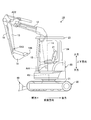
- FIG. 1 is a perspective view illustrating an example of a work vehicle according to the first embodiment.
- FIG. 2 is a side view showing an example of the work vehicle according to the first embodiment.
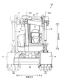
- FIG. 3 is a front view showing an example of the work vehicle according to the first embodiment.
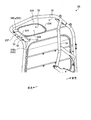
- FIG. 4 is a perspective view of the canopy according to the first embodiment viewed from below.
- FIG. 5 is a rear view of the canopy according to the first embodiment.
- FIG. 6 is a plan view of the canopy according to the first embodiment as viewed from above.
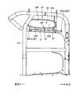
- FIG. 7 is a side view showing the canopy according to the first embodiment.
- FIG. 8 is an enlarged view of a partial cross section of the canopy according to the first embodiment.
- FIG. 9 is a plan view of the flange member according to the first embodiment as viewed from above.
- FIG. 9 is a plan view of the flange member according to the first embodiment as viewed from above.
- FIG. 10 is a plan view of the flange member according to the first embodiment as viewed from the rear.
- FIG. 11 is a side view showing the flange member according to the first embodiment.
- FIG. 12 is a side sectional view of the eaves member according to the first embodiment.
- FIG. 13 is a schematic diagram for explaining the operation of the flange member according to the first embodiment.
- FIG. 14 is a perspective view of the canopy according to the second embodiment viewed from below.
- FIG. 15 is a plan view of the canopy according to the second embodiment as viewed from above.
- FIG. 16 is an enlarged view of a partial cross section of the canopy according to the second embodiment.
- FIG. 17 is a perspective view showing a flange member according to the second embodiment.
- FIG. 18 is a plan view of the flange member according to the second embodiment as viewed from above.
- FIG. 19 is a plan view of the flange member according to the second embodiment as viewed from the rear.
- FIG. 20 is a side cross-sectional view of the flange member according to the second embodiment.
- FIG. 21 is a perspective view in which a part of the cab according to the third embodiment is broken and viewed from below.
- FIG. 22 is a plan view of the cab according to the third embodiment as viewed from above.
- FIG. 23 is a perspective view showing a flange member according to the third embodiment.
- FIG. 24 is a plan view of the flange member according to the third embodiment as viewed from above.
- Drawing 25 is a figure which looked at the collar member concerning a 3rd embodiment from back.
- FIG. 26 is a side cross-sectional view of the flange member according to the third embodiment.
- FIG. 1 is a perspective view showing an example of a work vehicle 1A according to the present embodiment.
- FIG. 2 is a side view showing an example of the work vehicle 1A according to the present embodiment.
- FIG. 3 is a front view showing an example of a work vehicle 1A according to the present embodiment.
- the work vehicle 1A is a hydraulic excavator 1A.
- a hydraulic excavator 1 ⁇ / b> A includes a working machine 10 that is operated by hydraulic pressure, a vehicle body 20 having a driver's seat 21, a traveling device 30 that supports the vehicle body 20, and a blade 40.
- the work machine 10 is supported by the vehicle body 20.
- the work machine 10 is an offset work machine having a so-called offset boom.
- the work implement 10 includes a main boom 11 connected to the vehicle body 20, an offset boom 12 connected to the main boom 11, an arm 13 connected to the offset boom 12, and a bucket 14 connected to the arm 13.
- the bucket 14 has a plurality of convex blades.
- a plurality of cutting edges 14B, which are the tips of the blades, are provided. Note that the cutting edge 14B of the bucket 14 may be the tip of a straight blade provided in the bucket 14.
- the vehicle body 20 and the main boom 11 are connected via a boom pin.
- the main boom 11 is supported by the vehicle body 20 so as to be rotatable about the rotation axis AX1.
- the main boom 11 and the offset boom 12 are connected via a first offset pin.
- the offset boom 12 is supported by the main boom 11 so as to be rotatable about the offset shaft BX1.
- the offset boom 12 and the arm 13 are connected via an arm pin.
- the arm 13 is supported by the offset boom 12 so as to be rotatable about the rotation axis AX2.
- the offset boom 12 and the arm 13 are connected via a second offset pin.
- the arm 13 is supported by the offset boom 12 so as to be rotatable about the offset axis BX2.
- the arm 13 and the bucket 14 are connected via a bucket pin.
- the bucket 14 is supported by the arm 13 so as to be rotatable about the rotation axis AX3.
- the vehicle body 20 is disposed above the traveling device 30 and can turn around the turning axis RX while being supported by the traveling device 30.
- the vehicle main body 20 is appropriately referred to as an upper turning body 20
- the traveling device 30 is appropriately referred to as a lower traveling body 30.
- the rotation axis AX1, the rotation axis AX2, and the rotation axis AX3 are parallel to each other.
- the rotation axes AX1, AX2, AX3 are orthogonal to the axis parallel to the turning axis RX.
- the direction parallel to the rotation axes AX1, AX2, and AX3 is appropriately referred to as the vehicle width direction of the upper swing body 20, and the direction parallel to the swing axis RX is appropriately set as the vertical direction of the upper swing body 20,
- the direction orthogonal to both the rotation axes AX1, AX2, AX3 and the turning axis RX is appropriately referred to as the front-rear direction of the upper turning body 20.
- the direction in which the bucket 14 is present with respect to the driver seated in the driver's seat 21 is the front, and the reverse direction in the front is the rear.
- One in the vehicle width direction is to the right, and the opposite direction to the right is to the left.
- the bucket 14 is disposed in front of the upper swing body 20.
- the plurality of cutting edges 14B of the bucket 14 are arranged in the vehicle width direction.
- the blade 40 is disposed in front of the lower traveling body 30.
- the hydraulic excavator 1 ⁇ / b> A includes a boom cylinder 15 that drives the main boom 11, an offset cylinder 16 that drives the offset boom 12, an arm cylinder 17 that drives the arm 13, and a bucket cylinder 18 that drives the bucket 14.
- the boom cylinder 15 When the boom cylinder 15 is operated, the base end portion of the main boom 11 rotates about the rotation axis AX1, and the tip end portion of the main boom 11 moves in the vertical direction.
- the arm cylinder 17 When the arm cylinder 17 is operated, the base end portion of the arm 13 rotates about the rotation axis AX2, and the tip end portion of the arm 13 moves in the vertical direction.
- the bucket cylinder 18 is actuated, the base end portion of the bucket 14 rotates about the rotation axis AX3, and the blade edge 14B of the bucket 14 moves in the vertical direction.
- the work machine 10 that is an offset type work machine can move the bucket 14 in the vehicle width direction of the upper swing body 20.
- the offset axes BX1, BX2 are orthogonal to the rotation axes AX1, AX2, AX3.
- the offset cylinder 16 operates and the offset boom 12 rotates about the offset shaft BX1, whereby the arm 13 and the bucket 14 move in the vehicle width direction.
- the arm 13 rotates about the offset axis BX2.
- the arm 13 and the bucket 14 are translated in the vehicle width direction while the state where the plurality of cutting edges 14B are arranged in the vehicle width direction is maintained.
- the bucket 14 is disposed in front of the upper swing body 20. As shown in FIG. 3, the bucket 14 is movable in front of the driver seat 21 by the operation of the offset cylinder 16.
- the upper swing body 20 includes a driver seat 21 on which the driver is seated, a canopy 23 that is disposed above the driver seat 21 and supports the skylight 22, a support column 24 that supports the canopy 23, and a driver.
- the operation lever 25 is operated.
- the skylight 22 is disposed directly above the driver seat 21 or above and in front of the driver seat 21.
- the operation lever 25 includes a work machine lever 25A for operating the work machine 10 and a travel lever 25B for operating the lower travel body 30.
- the work machine lever 25A is arranged on each of the right side and the left side of the driver's seat 21.
- the travel lever 25 ⁇ / b> B is disposed in front of the driver seat 21.
- the lower traveling body 30 has a pair of crawlers 31. As the crawler 31 rotates, the excavator 1A travels. In addition, the lower traveling body 30 may have a tire.
- the hydraulic excavator 1 ⁇ / b> A has a headlamp 2.
- the headlamp 2 is supported by the main boom 11.
- the headlamp 2 is disposed below the canopy 23 in the vertical direction.
- the headlamp 2 emits illumination light forward and downward from the position where the headlamp 2 is provided.
- the headlamp 2 emits illumination light to illuminate the bucket 14 and the excavation site by the bucket 14.
- excavation work is carried out while illuminating the bucket 14 of the work implement 10 with the headlamp 2.
- the bucket 14 excavates an excavation site below the canopy 23 in front of the upper swing body 20 including the canopy 23.
- the headlamp 2 illuminates the bucket 14 that exists in front of and below the canopy 23.
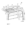
- FIG. 4 is a perspective view of the canopy 23 according to this embodiment as viewed from below.
- FIG. 5 is a view of the canopy 23 according to the present embodiment as viewed from the rear.
- FIG. 6 is a plan view of the canopy 23 according to the present embodiment as viewed from above.
- FIG. 7 is a side view showing the canopy 23 according to the present embodiment.
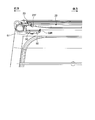
- FIG. 8 is an enlarged view of a partial cross section of the canopy 23 according to the present embodiment.
- the hydraulic excavator 1A includes a gutter member 50 having a light shielding surface 51 that blocks light from entering the skylight 22 from the front side of the upper swing body 20.
- the eaves member 50 is supported by the canopy 23.
- the canopy 23 has an opening 23K in which the skylight 22 is disposed.
- the skylight 22 is disposed in the opening 23K of the canopy 23.
- the skylight 22 is a transparent member.
- the skylight 22 has an upper surface 22A facing upward and a lower surface 22B facing downward.
- the upper surface 22A of the skylight 22 is a flat surface.
- the lower surface 22B of the skylight 22 is a flat surface.
- the upper surface 22A and the lower surface 22B are substantially parallel.
- the skylight 22 is a parallel plate.
- the canopy 23 has an upper surface 23A facing upward and a lower surface 23B facing downward.
- the upper surface 23A of the canopy 23 is a flat surface.
- the lower surface 23B of the canopy 23 is a flat surface.
- the upper surface 23A and the lower surface 23B are substantially parallel.
- the bucket 14 In order to illuminate the bucket 14 disposed in front of the upper swing body 20 and below the canopy 23 with the headlamp 2, when the illumination light is emitted from the headlamp 2, the bucket 14 is irradiated. At least a part of the illumination light is reflected by the bucket 14 and enters the skylight 22 from the lower surface 22B of the skylight 22. When at least part of the illumination light reflected by the bucket 14 enters the skylight 22, a virtual image of the bucket 14 may be formed on the skylight 22. That is, there is a possibility that a reflection phenomenon in which the virtual image of the bucket 14 is reflected on the skylight 22 may occur.
- the work machine 10 is an offset type work machine, and the bucket 14 may be disposed in front of the driver's seat 21.
- the bucket 14 arranged in front of the driver's seat 21 is illuminated by the headlamp 2, there is a high possibility that a reflection phenomenon will occur.
- At least a part of the work machine 10 may be moved above the canopy 23.
- the arm cylinder 17 may be moved above the canopy 23.
- the driver may check the state of the work implement 10 by visually observing the portion (the highest reachable portion) of the work implement 10 that has been moved upward such as the arm cylinder 17 through the skylight 22.
- the reflection phenomenon in which the virtual image of the bucket 14 is formed on the skylight 22 it becomes difficult for the driver to visually observe the real image of the highest reachable part of the work machine 10 via the skylight 22.
- the eaves member 50 blocks the illumination light reflected by the bucket 14 disposed in front of the upper swing body 20 from entering the lower surface 22B of the skylight 22. By blocking the illumination light from entering the skylight 22, the occurrence of the reflection phenomenon in which the virtual image of the bucket 14 is formed on the skylight 22 is suppressed.
- the eaves member 50 is a light shielding member in which light transmission is suppressed.
- the eaves member 50 is formed of a metal such as stainless steel.
- the flange member 50 may be formed of a synthetic resin.
- the saddle member 50 is disposed on the lower surface 23B of the canopy 23. At least a part of the eaves member 50 is disposed rearward from the front end 22F of the skylight 22.
- the front end portion 23F of the canopy 23 refers to the foremost part of the lower surface 23B of the canopy 23.
- the front end portion 22F of the skylight 22 refers to the foremost portion of the lower surface 22B of the skylight 22.
- the front end 22 ⁇ / b> F of the skylight 22 includes a boundary between the lower surface 23 ⁇ / b> B of the canopy 23 and the lower surface 22 ⁇ / b> B of the skylight 22.
- the light shielding surface 51 is the lower surface of the eaves member 50 facing downward, and blocks light from entering the skylight 22. At least a part of the light shielding surface 51 is disposed below the lower surface 23 ⁇ / b> B of the canopy 23 behind the front end 22 ⁇ / b> F of the skylight 22.
- the front end portion 50F of the flange member 50 is connected to the front end portion 23F of the canopy 23.
- the rear end portion 50 ⁇ / b> R of the flange member 50 is separated from the canopy 23 and the skylight 22.
- the front end portion 50 ⁇ / b> F of the flange member 50 refers to the foremost part of the flange member 50.
- the rear end portion 50 ⁇ / b> R of the flange member 50 refers to the rearmost part of the flange member 50.
- the rear end portion 50 ⁇ / b> R of the gutter member 50 is disposed behind the front end portion 22 ⁇ / b> F of the skylight 22. That is, the gutter member 50 and the skylight 22 slightly overlap in plan view substantially parallel to the lower surface 22B.
- the overlapping area Da between the eaves member 50 and the skylight 22 in the front-rear direction is smaller than the non-overlapping area Db between the eaves member 50 and the skylight 22.
- the overlapping region Da includes a region where the lower surface 22B of the skylight 22 faces the heel member 50.
- the non-overlapping region Db includes a region where the lower surface 22B of the skylight 22 does not face the gutter member 50.
- the dimension of the skylight 22 in the front-rear direction is 500 [mm] or more and 600 [mm] or less.
- the dimension of the overlap region Da in the front-rear direction is 10 [mm] or more and 100 [mm] or less.
- the dimension of the gutter member 50 in the vehicle width direction is larger than the dimension of the skylight 22.
- the dimension of the skylight 22 in the vehicle width direction is 300 [mm] or more and 500 [mm] or less.
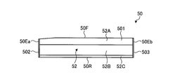
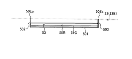
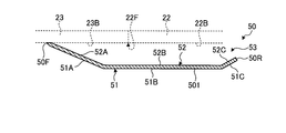
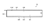
- FIG. 9 is a plan view of the eaves member 50 according to the present embodiment as viewed from above.
- FIG. 10 is a view of the flange member 50 according to the present embodiment as viewed from the rear.
- FIG. 11 is a side view showing the flange member 50 according to this embodiment.
- FIG. 12 is a side sectional view of the flange member 50 according to the present embodiment.
- the eaves member 50 is formed by a plate member.
- the eaves member 50 may be formed by bending a flat plate member, or may be formed by combining a plurality of plate members.
- the flange member 50 includes a light shielding plate portion 501 and a pair of side plate portions 502 and 503 disposed on both sides of the light shielding plate portion 501 in the vehicle width direction.
- the eaves member 50 has an upper surface 52 that faces the lower surface 23B of the canopy 23 with a gap.
- the light shielding surface 51 and the upper surface 52 are disposed on the light shielding plate portion 501.
- the front end portion 50F of the saddle member 50 and one end portion 50Ea and the other end portion 50Eb of the saddle member 50 in the vehicle width direction are connected to the canopy 23.
- An opening 53 is provided between the lower surface 23B of the canopy 23 and the rear end portion 50R of the upper surface 52 of the flange member 50.
- the end portion 50Ea is disposed on the side plate portion 502.
- the end portion 50Eb is disposed on the side plate portion 503.
- the light shielding surface 51 of the flange member 50 is inclined downward toward the rear of the upper swing body 20.
- the light shielding surface 51 includes an inclined region 51A inclined downward from the front end portion 50F of the flange member 50 and a flat region 51B provided behind the inclined region 51A. And an inclined region 51C provided behind the flat region 51B and inclined upward toward the rear.
- the upper surface 52 of the flange member 50 is inclined downward toward the rear of the upper swing body 20.
- the upper surface 52 includes an inclined region 52A inclined downward from the front end 50F of the flange member 50 toward the rear, and a flat region 52B provided rearward of the inclined region 52A.
- an inclined region 52C that is provided behind the flat region 52B and is inclined upward toward the rear.
- the gutter member 50 is formed so that the flat area 51B and the flat area 52B are parallel to the horizontal plane.
- FIG. 13 is a schematic diagram for explaining the operation of the eaves member 50 according to the present embodiment.
- the skylight 22 is provided with illumination light emitted from the headlamp 2 and reflected light of illumination light emitted from the headlamp 2 and reflected by the bucket 14.
- a non-incident area A is formed in which both are not incident.
- region A is provided in the one part area
- the non-incident area A is a non-reflection area A where the virtual image of the bucket 14 is not reflected.
- At least one of the illumination light emitted from the headlamp 2 and the reflected light of the illumination light emitted from the headlamp 2 and reflected by the bucket 14 is incident behind the non-reflection area A.
- the incident region B to be formed is formed.
- the incident area B is a reflection range B in which a virtual image of the bucket 14 may be reflected.
- the non-reflection area A can be increased by increasing the overlapping area Da between the gutter member 50 and the skylight 22.
- the overlap area Da is too large, the saddle member 50 becomes an obstacle when the driver seated in the driver's seat 21 visually observes the highest reachable part of the work implement 10 through the skylight 22.
- the headlamp 2 is not used, and no reflection phenomenon occurs. Therefore, it is preferable that the overlapping area Da is not excessively large.
- the reflection range B is formed in the night excavation work
- the size is necessary and sufficient for viewing the real image of the highest reachable part of the work machine 10 through the skylight 22.
- a non-reflection area A is formed. Therefore, the confirmation work of the highest reaching part of the work machine 10 can be smoothly performed even in the night excavation work without hindering the confirmation work of the highest reaching part of the work machine 10 in the daytime excavation work.
- the standard eyepoint EP of the driver sitting on the driver's seat 21 is defined behind the front end 22F of the skylight 22.
- the standard eye point EP is the position of the driver's eyes that is assumed when a driver with a standard physique is seated on the driver's seat 21.
- the standard eye point EP may be obtained statistically from the positions of the eyes of a plurality of drivers seated on the driver seat 21, for example.
- the rear end portion 50R of the gutter member 50 is disposed in front of a virtual line VL connecting the standard eye point EP and the front end portion 22F of the skylight 22.
- At least a portion is disposed below the lower surface 23B of the canopy 23 between the front end portion 23F of the canopy 23 and the front end portion 22F of the skylight 22, and the upper swing body 20
- the eaves member 50 having the light shielding surface 51 that blocks light incident on the skylight 22 from the front is provided, the occurrence of the reflection phenomenon of the bucket 14 in the skylight 22 can be suppressed. Therefore, the driver seated in the driver's seat 21 can visually check the real image of the highest reachable part of the work machine 10 through the skylight 22, and can smoothly check the state of the work machine 10.
- the rear end portion 50R of the gutter member 50 is disposed behind the front end portion 22F of the skylight 22.
- the overlapping area Da between the eaves member 50 and the skylight 22 in the front-rear direction is smaller than the non-overlapping area Db between the eaves member 50 and the skylight 22.
- the standard eye point EP of the driver sitting on the driver's seat 21 is defined behind the front end portion 22F of the skylight 22, and the rear end portion 50R of the gutter member 50 is defined as the standard eye point EP. It arrange
- the work machine 10 is an offset type work machine that can move the bucket 14 in the vehicle width direction of the upper swing body 20.
- the reflection phenomenon of the bucket 14 is likely to occur when the bucket 14 is disposed in front of the driver's seat 21 and the skylight 22 and the bucket 14 is illuminated by the headlamp 2. Therefore, the provision of the eaves member 50 in the hydraulic excavator 1A having the work implement 10 can effectively suppress the occurrence of the reflection phenomenon.
- the lower surface 23B of the canopy 23 is a flat surface.
- the manufacturing cost of the canopy 23 can be reduced compared to making the lower surface 23B of the canopy 23 curved or complex.
- the lower surface 23B of the canopy 23 is a flat surface, there is a high possibility that a reflection phenomenon will occur. By providing the canopy 23 with such a canopy member 23, it is possible to effectively suppress the occurrence of the reflection phenomenon.
- At least a part of the light shielding surface 51 is inclined downward toward the rear. Therefore, the line of sight when the driver seated in the driver's seat 21 looks forward is not obstructed, and the driver can check the front smoothly.
- the size of the eaves member 50 in the vehicle width direction is larger than the size of the skylight 22. Therefore, the occurrence of the reflection phenomenon is effectively suppressed.
- the front end portion 50F of the flange member 50 and both end portions 50E (50Ea, 50Eb) of the flange member 50 are connected to the canopy 23.
- the upper surface 52 of the flange member 50 and the lower surface 23B of the canopy 23 are opposed to each other with a gap.
- An opening 53 is provided between the lower surface 23B of the canopy 23 and the rear end portion 50R of the upper surface 52 of the flange member 50. Since a space is provided between the flange member 50 and the canopy 23, the space can be used as, for example, an article storage unit. Since the opening 53 opens rearward, the driver can put an article into the space between the eaves member 50 and the canopy 23 through the opening 53 while sitting on the driver's seat 21, or the eaves member Articles can be taken out from the space between 50 and the canopy 23.
- the upper surface 52 of the flange member 50 includes an inclined region 52A inclined downward from the front end portion 50F of the flange member 50 and a flat region 52B provided behind the inclined region 52A. ,including.
- the flat region 52B By providing the flat region 52B, the article is stably disposed in the flat region 52B.
- the inclined region 52A is provided, it is possible to prevent the article from falling forward from the space between the flange member 50 and the canopy 23.
- the upper surface 52 of the flange member 50 is provided with an inclined region 52C that is disposed rearward of the flat region 52B and inclined upward toward the rear. Therefore, it is also possible to prevent the article from falling backward from the space between the flange member 50 and the canopy 23.
- the dimension of the inclined region 52C in the front-rear direction is smaller than the dimension of the inclined region 52A. Therefore, the driver 53 can smoothly take out the article when taking out the article from the space between the eaves member 50 and the canopy 23 through the opening 53.
- FIG. 14 is a perspective view of the canopy 23 according to the present embodiment as viewed from below.
- FIG. 15 is a plan view of the canopy 23 according to this embodiment as viewed from above.
- FIG. 16 is an enlarged view of a partial cross section of the canopy according to the second embodiment.
- the excavator 1B includes a gutter member 50 having a light shielding surface 51 that blocks light from entering the skylight 22 from the front side of the upper swing body 20.
- the excavator 1 ⁇ / b> B has a protect bar 60 disposed so as to face the upper surface 22 ⁇ / b> A of the skylight 22.
- a plurality of protect bars 60 are arranged in the vehicle width direction. Each of the plurality of protect bars 60 is arranged to extend in the front-rear direction.
- FIG. 17 is a perspective view showing the eaves member 50 according to the present embodiment.
- FIG. 18 is a plan view of the flange member 50 according to the present embodiment as viewed from above.
- FIG. 19 is a view of the flange member 50 according to the present embodiment as viewed from the rear.
- FIG. 20 is a side sectional view of the flange member 50 according to the present embodiment.
- the eaves member 50 is formed by a plate member.
- the eaves member 50 includes a light shielding plate portion 501 and a side plate portion 502 disposed at one end of the light shielding plate portion 501 in the vehicle width direction.
- the saddle member 50 has an upper surface 52 that faces the lower surface 23B of the canopy 23 with a gap.
- the light shielding surface 51 and the upper surface 52 are disposed on the light shielding plate portion 501.
- the front end portion 50F of the saddle member 50 and one end portion 50Ea of the saddle member 50 in the vehicle width direction are connected to the canopy 23.
- One end portion 50Ea is disposed on the side plate portion 502.
- An opening 53 is provided between the lower surface 23B of the canopy 23 and the rear end portion 50R of the upper surface 52 of the flange member 50.
- the opening 54 is also provided between the lower surface 23B of the canopy 23 and the other end portion of the upper surface 52 of the flange member 50 in the vehicle width direction.
- the cover member 29 is provided at the rear end portion 50R of the flange member 50.
- the light shielding plate 51 includes a vertical surface area 51AF that includes the front end 50F of the flange member 50 and extends in the vertical direction, and a flat surface provided behind the vertical surface area 51AF. It includes a region 51B and an inclined region 51C that is provided behind the flat region 51B and is inclined upward toward the rear.
- the upper surface 52 includes a vertical surface region 52AF including the front end portion 50F of the flange member 50 and extending in the vertical direction, and a flat surface provided behind the vertical surface region 52AF.
- the region 52B includes an inclined region 52C that is provided behind the flat region 52B and is inclined upward toward the rear.
- the flat area 51B and the flat area 52B are provided so as to be parallel to the horizontal plane.
- the vertical surface area 51AF and the vertical surface area 52AF are provided so as to be orthogonal to the horizontal plane.
- the space can be used as an article storage unit.
- the driver since the opening 53 that opens to the rear and the opening 54 that opens to the right are provided, the driver can use the saddle member through one or both of the opening 53 and the opening 54. Articles can be put into the space between 50 and the canopy 23, or articles can be taken out from the space between the gutter member 50 and the canopy 23.
- the upper surface 52 of the flange member 50 is provided with an inclined region 52C that is disposed rearward of the flat region 52B and inclined upward toward the rear. Therefore, it is also possible to prevent the article from falling backward from the space between the flange member 50 and the canopy 23.
- the vertical surface region 52AF extending in the vertical direction is provided on the upper surface 52 of the heel member 50, the article falls forward from the space between the heel member 50 and the canopy 23. Is suppressed.
- the example in which the upper swing body 20 has a canopy specification in which the driver's seat 21 is disposed in a substantially open space has been described.
- an example in which the upper swing body 20 has a cab specification in which the driver's seat 21 is disposed in a substantially closed space will be described.
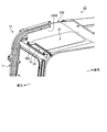
- FIG. 21 is a perspective view in which a part of the cab 70 of the excavator 1C according to the present embodiment is broken and viewed from below.
- FIG. 22 is a plan view of the cab 70 according to this embodiment as viewed from above.
- the excavator 1C includes a cab 70 having an internal space in which a driver's seat is arranged.
- the cab 70 includes a front member 71 disposed in front of the driver seat, a rear member 72 disposed rearward of the driver seat, a side member 73 disposed on the left side of the driver seat, and the driver seat.
- the top plate member 230 has an upper surface 230A facing upward and a lower surface 230B facing downward.
- the upper surface 230A is a flat surface.
- the lower surface 230B is a flat surface.
- the hydraulic excavator 1 ⁇ / b> C includes a gutter member 50 having a light blocking surface 51 that blocks light from entering the skylight 22 from the front of the upper swing body 20.
- the eaves member 50 is disposed in a cab that is an internal space of the cab 70.
- FIG. 23 is a perspective view showing the eaves member 50 according to the present embodiment.
- FIG. 24 is a plan view of the flange member 50 according to the present embodiment as viewed from above.
- FIG. 25 is a view of the flange member 50 according to the present embodiment as viewed from the rear.
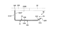
- FIG. 26 is a side sectional view of the flange member 50 according to the present embodiment.
- the eaves member 50 is formed by a plate member.
- the eaves member 50 includes a light shielding plate 501, a side plate 502 disposed at one end of the light shielding plate 501 in the vehicle width direction, and a side plate 503 disposed at the other end.
- the eaves member 50 has an upper surface 52 that faces the lower surface 230B of the top plate member 230 with a gap therebetween.
- the light shielding surface 51 and the upper surface 52 are disposed on the light shielding plate portion 501.
- the front end portion 50F of the saddle member 50 and one end portion 50Ea and the other end portion 50Eb of the saddle member 50 in the vehicle width direction are connected to the top plate member 230.
- One end portion 50Ea is disposed on the side plate portion 502.
- the other end 50Eb is disposed on the side plate 503.
- An opening 53 is provided between the lower surface 230 ⁇ / b> B of the top plate member 230 and the rear end portion 50 ⁇ / b> R of the upper surface 52 of the gutter member 50.
- the light shielding surface 51 includes a vertical surface region 51AF that includes the front end portion 50F of the flange member 50 and extends in the vertical direction, and a flat region that is provided behind the vertical surface region 51AF. 51B and an inclined region 51C that is provided behind the flat region 51B and is inclined upward toward the rear.
- the upper surface 52 includes a vertical surface region 52AF that includes the front end portion 50F of the flange member 50 and extends in the vertical direction, and a flat surface provided behind the vertical surface region 52AF.
- the region 52B includes an inclined region 52C that is provided behind the flat region 52B and is inclined upward toward the rear.
- the space can be used as an article storage unit.
- the work vehicle is a hydraulic excavator, but is not limited to a hydraulic excavator.
- the gutter member 50 described in each of the above embodiments can be applied to all work vehicles including a roof member that supports a skylight above the driver's seat.
Landscapes
- Engineering & Computer Science (AREA)
- Mining & Mineral Resources (AREA)
- Civil Engineering (AREA)
- General Engineering & Computer Science (AREA)
- Structural Engineering (AREA)
- Mechanical Engineering (AREA)
- Component Parts Of Construction Machinery (AREA)
- Body Structure For Vehicles (AREA)
Abstract
Description
第1実施形態について説明する。図1は、本実施形態に係る作業車両1Aの一例を示す斜視図である。図2は、本実施形態に係る作業車両1Aの一例を示す側面図である。図3は、本実施形態に係る作業車両1Aの一例を示す正面図である。本実施形態においては、作業車両1Aが油圧ショベル1Aである例について説明する。
第2実施形態について説明する。以下の説明において、上述の実施形態と同一又は同等の構成要素については同一の符号を付し、その説明を簡略又は省略する。
第3実施形態について説明する。以下の説明において、上述の実施形態と同一又は同等の構成要素については同一の符号を付し、その説明を簡略又は省略する。
2 前照灯
10 作業機
11 メインブーム
12 オフセットブーム
13 アーム
14 バケット
14B 刃先
15 ブームシリンダ
16 オフセットシリンダ
17 アームシリンダ
18 バケットシリンダ
20 上部旋回体(車両本体)
21 運転席
22 天窓
22A 上面
22B 下面
22F 前端部
23 キャノピー(屋根部材)
23A 上面
23B 下面
23F 前端部
23K 開口
24 支柱
25 操作レバー
25A 作業機レバー
25B 走行レバー
29 カバー部材
30 下部走行体(走行装置)
31 クローラ
40 ブレード
50 庇部材
50Ea 一方の端部
50Eb 他方の端部
50F 前端部
50R 後端部
51 遮光面(下面)
51A 傾斜領域
51AF 垂直面領域
51B 平坦領域
51C 傾斜領域
52 上面
52A 傾斜領域
52B 平坦領域
52C 傾斜領域
53 開口部
54 開口部
60 プロテクトバー
70 キャブ
71 前面部材
72 後面部材
73 側面部材
74 側面部材
230 天板部材
230A 上面
230B 下面
501 遮光板部
502 側板部
503 側板部
A 非映り込み範囲(非入射領域)
B 映り込み範囲(入射領域)
AX1,AX2,AX3 回転軸
BX1,BX2 オフセット軸
Da 重複領域
Db 非重複領域
RX 旋回軸
Claims (8)
- 運転席を有する車両本体と、
前記車両本体よりも前方に配置されるバケットを有し、前記車両本体に支持される作業機と、
前記運転席よりも上方に配置され、天窓を支持する屋根部材と、
少なくとも一部が前記天窓の前端部から後方の前記屋根部材の下面に配置され、前記天窓に対する光の入射を遮る遮光面を有する庇部材と、
を備える作業車両。 - 前記庇部材の後端部は、前記天窓の前端部よりも後方に配置され、
前記車両本体の前後方向の前記庇部材と前記天窓との重複領域の寸法は、前記庇部材と前記天窓との非重複領域の寸法よりも小さい、
請求項1に記載の作業車両。 - 前記運転席に着座する運転者の標準アイポイントが前記天窓の前端部よりも後方に規定され、
前記庇部材の後端部は、前記標準アイポイントと前記天窓の前端部とを結ぶ仮想線よりも前方に配置される、
請求項2に記載の作業車両。 - 前記作業機は、前記車両本体の車幅方向に前記バケットを移動可能なオフセット式作業機である、
請求項1から請求項3のいずれか一項に記載の作業車両。 - 前記遮光面の少なくとも一部は、前記車両本体の後方に向かって下方に傾斜する、
請求項1から請求項4のいずれか一項に記載の作業車両。 - 前記車両本体の車幅方向における前記庇部材の寸法は、前記天窓の寸法よりも大きい、
請求項1から請求項5のいずれか一項に記載の作業車両。 - 前記庇部材の前端部及び前記車幅方向の前記庇部材の端部が前記屋根部材と接続され、
前記庇部材の上面と前記屋根部材の下面とは間隙を介して対向し、
前記屋根部材の下面と前記庇部材の上面の後端部との間に開口部が設けられる、
請求項6に記載の作業車両。 - 前記庇部材の上面は、前記庇部材の前端部から後方に向かって下方に傾斜する傾斜領域と、前記傾斜領域よりも後方に設けられる平坦領域と、を含む、
請求項7に記載の作業車両。
Priority Applications (4)
| Application Number | Priority Date | Filing Date | Title |
|---|---|---|---|
| DE112016000021.9T DE112016000021B4 (de) | 2016-01-28 | 2016-01-28 | Arbeitsfahrzeug |
| CN201680000992.5A CN106232904B (zh) | 2016-01-28 | 2016-01-28 | 作业车辆 |
| PCT/JP2016/052438 WO2016114407A1 (ja) | 2016-01-28 | 2016-01-28 | 作業車両 |
| JP2016509806A JP6675302B2 (ja) | 2016-01-28 | 2016-01-28 | 作業車両 |
Applications Claiming Priority (1)
| Application Number | Priority Date | Filing Date | Title |
|---|---|---|---|
| PCT/JP2016/052438 WO2016114407A1 (ja) | 2016-01-28 | 2016-01-28 | 作業車両 |
Publications (1)
| Publication Number | Publication Date |
|---|---|
| WO2016114407A1 true WO2016114407A1 (ja) | 2016-07-21 |
Family
ID=56405946
Family Applications (1)
| Application Number | Title | Priority Date | Filing Date |
|---|---|---|---|
| PCT/JP2016/052438 Ceased WO2016114407A1 (ja) | 2016-01-28 | 2016-01-28 | 作業車両 |
Country Status (4)
| Country | Link |
|---|---|
| JP (1) | JP6675302B2 (ja) |
| CN (1) | CN106232904B (ja) |
| DE (1) | DE112016000021B4 (ja) |
| WO (1) | WO2016114407A1 (ja) |
Cited By (1)
| Publication number | Priority date | Publication date | Assignee | Title |
|---|---|---|---|---|
| US11447087B2 (en) * | 2018-03-09 | 2022-09-20 | Doosan Infracore Co., Ltd. | Canopy assembly of construction machinery |
Citations (3)
| Publication number | Priority date | Publication date | Assignee | Title |
|---|---|---|---|---|
| JP2000073407A (ja) * | 1998-08-28 | 2000-03-07 | Sumitomo Constr Mach Co Ltd | 建設機械の天窓構造 |
| JP2002029254A (ja) * | 2000-07-12 | 2002-01-29 | Komatsu Ltd | 車輌用サンバイザー |
| JP2007050785A (ja) * | 2005-08-18 | 2007-03-01 | Hitachi Constr Mach Co Ltd | 建設機械 |
Family Cites Families (11)
| Publication number | Priority date | Publication date | Assignee | Title |
|---|---|---|---|---|
| JP2591077Y2 (ja) * | 1993-10-16 | 1999-02-24 | 油谷重工株式会社 | 建設機械のキャブ |
| JP2000048407A (ja) | 1998-07-29 | 2000-02-18 | Sony Corp | 光記録媒体、光記録媒体製造用原盤及び光記録再生装置 |
| JP2003049449A (ja) * | 2001-08-07 | 2003-02-21 | Hitachi Constr Mach Co Ltd | 建設機械の反射防止装置 |
| JP4323352B2 (ja) * | 2004-03-15 | 2009-09-02 | 日立建機株式会社 | 建設機械 |
| JP2005280583A (ja) * | 2004-03-30 | 2005-10-13 | Tamura Plastic Mfg Co Ltd | 自動車用バイザー |
| JP4596982B2 (ja) * | 2004-06-11 | 2010-12-15 | 株式会社小松製作所 | 建設機械のキャブ |
| JP4284660B2 (ja) * | 2005-04-15 | 2009-06-24 | 株式会社ホンダアクセス | 車両用ルーフコンソールボックス |
| CN201923791U (zh) * | 2010-12-30 | 2011-08-10 | 长沙中联重工科技发展股份有限公司 | 工程车辆的操纵室 |
| CN202006717U (zh) * | 2011-02-21 | 2011-10-12 | 浙江吉利汽车研究院有限公司 | 可拉伸遮阳板 |
| JP2014034336A (ja) * | 2012-08-10 | 2014-02-24 | Yachiyo Industry Co Ltd | サンシェード装置 |
| CN207878542U (zh) * | 2017-07-15 | 2018-09-18 | 天津瀚侨车体制造有限公司 | 一种挖掘机驾驶室的天窗 |
-
2016
- 2016-01-28 DE DE112016000021.9T patent/DE112016000021B4/de active Active
- 2016-01-28 WO PCT/JP2016/052438 patent/WO2016114407A1/ja not_active Ceased
- 2016-01-28 JP JP2016509806A patent/JP6675302B2/ja active Active
- 2016-01-28 CN CN201680000992.5A patent/CN106232904B/zh active Active
Patent Citations (3)
| Publication number | Priority date | Publication date | Assignee | Title |
|---|---|---|---|---|
| JP2000073407A (ja) * | 1998-08-28 | 2000-03-07 | Sumitomo Constr Mach Co Ltd | 建設機械の天窓構造 |
| JP2002029254A (ja) * | 2000-07-12 | 2002-01-29 | Komatsu Ltd | 車輌用サンバイザー |
| JP2007050785A (ja) * | 2005-08-18 | 2007-03-01 | Hitachi Constr Mach Co Ltd | 建設機械 |
Cited By (1)
| Publication number | Priority date | Publication date | Assignee | Title |
|---|---|---|---|---|
| US11447087B2 (en) * | 2018-03-09 | 2022-09-20 | Doosan Infracore Co., Ltd. | Canopy assembly of construction machinery |
Also Published As
| Publication number | Publication date |
|---|---|
| CN106232904B (zh) | 2021-07-06 |
| CN106232904A (zh) | 2016-12-14 |
| DE112016000021T5 (de) | 2016-12-01 |
| JPWO2016114407A1 (ja) | 2018-11-15 |
| JP6675302B2 (ja) | 2020-04-01 |
| DE112016000021B4 (de) | 2022-10-27 |
Similar Documents
| Publication | Publication Date | Title |
|---|---|---|
| JP5775283B2 (ja) | 作業機械のモニタ装置 | |
| US9273447B2 (en) | Cab for construction machine and construction machine | |
| JP6340068B2 (ja) | 油圧ショベル | |
| CN101375003B (zh) | 工程作业机械 | |
| JP2002371595A (ja) | 建設機械 | |
| JP5130391B1 (ja) | 建設機械 | |
| JP6675302B2 (ja) | 作業車両 | |
| JP7158201B2 (ja) | 作業機械およびキャブ | |
| JP2002371594A (ja) | 建設機械 | |
| US10047496B2 (en) | Bulldozer | |
| JP6346676B2 (ja) | 油圧ショベル | |
| JP6110570B2 (ja) | 油圧ショベル | |
| EP4394136A1 (en) | Work machine | |
| JP7481089B2 (ja) | 作業車両 | |
| JP6283759B2 (ja) | 油圧ショベル | |
| JP2008095339A (ja) | 作業機械 | |
| JP7157091B2 (ja) | 作業用車両 | |
| JPH08326086A (ja) | 旋回型掘削装置 | |
| KR20120140122A (ko) | 건설기계용 아암 레스트 | |
| JP2003193510A (ja) | 建設機械のボンネット |
Legal Events
| Date | Code | Title | Description |
|---|---|---|---|
| ENP | Entry into the national phase |
Ref document number: 2016509806 Country of ref document: JP Kind code of ref document: A |
|
| 121 | Ep: the epo has been informed by wipo that ep was designated in this application |
Ref document number: 16737478 Country of ref document: EP Kind code of ref document: A1 |
|
| WWE | Wipo information: entry into national phase |
Ref document number: 112016000021 Country of ref document: DE |
|
| 122 | Ep: pct application non-entry in european phase |
Ref document number: 16737478 Country of ref document: EP Kind code of ref document: A1 |