WO2016114005A1 - 光学フィルムの製造方法 - Google Patents
光学フィルムの製造方法 Download PDFInfo
- Publication number
- WO2016114005A1 WO2016114005A1 PCT/JP2015/082876 JP2015082876W WO2016114005A1 WO 2016114005 A1 WO2016114005 A1 WO 2016114005A1 JP 2015082876 W JP2015082876 W JP 2015082876W WO 2016114005 A1 WO2016114005 A1 WO 2016114005A1
- Authority
- WO
- WIPO (PCT)
- Prior art keywords
- stretching
- clip
- interval
- film
- laminate
- Prior art date
- Legal status (The legal status is an assumption and is not a legal conclusion. Google has not performed a legal analysis and makes no representation as to the accuracy of the status listed.)
- Ceased
Links
Images



Classifications
-
- B—PERFORMING OPERATIONS; TRANSPORTING
- B29—WORKING OF PLASTICS; WORKING OF SUBSTANCES IN A PLASTIC STATE IN GENERAL
- B29C—SHAPING OR JOINING OF PLASTICS; SHAPING OF MATERIAL IN A PLASTIC STATE, NOT OTHERWISE PROVIDED FOR; AFTER-TREATMENT OF THE SHAPED PRODUCTS, e.g. REPAIRING
- B29C55/00—Shaping by stretching, e.g. drawing through a die; Apparatus therefor
- B29C55/02—Shaping by stretching, e.g. drawing through a die; Apparatus therefor of plates or sheets
- B29C55/04—Shaping by stretching, e.g. drawing through a die; Apparatus therefor of plates or sheets uniaxial, e.g. oblique
- B29C55/06—Shaping by stretching, e.g. drawing through a die; Apparatus therefor of plates or sheets uniaxial, e.g. oblique parallel with the direction of feed
-
- B—PERFORMING OPERATIONS; TRANSPORTING
- B29—WORKING OF PLASTICS; WORKING OF SUBSTANCES IN A PLASTIC STATE IN GENERAL
- B29C—SHAPING OR JOINING OF PLASTICS; SHAPING OF MATERIAL IN A PLASTIC STATE, NOT OTHERWISE PROVIDED FOR; AFTER-TREATMENT OF THE SHAPED PRODUCTS, e.g. REPAIRING
- B29C55/00—Shaping by stretching, e.g. drawing through a die; Apparatus therefor
- B29C55/02—Shaping by stretching, e.g. drawing through a die; Apparatus therefor of plates or sheets
- B29C55/20—Edge clamps
-
- G—PHYSICS
- G02—OPTICS
- G02B—OPTICAL ELEMENTS, SYSTEMS OR APPARATUS
- G02B5/00—Optical elements other than lenses
- G02B5/30—Polarising elements
Definitions
- the present invention relates to a method for producing an optical film.
- a long film is gripped and conveyed by a tenter clip, stretched by widening the interval in the conveying direction of the tenter clip, and the film is contracted in a direction substantially perpendicular to the conveying direction to produce an optical film.
- a technique is known (claim 7 of Patent Document 1). In such a stretching technique, there is a problem that unevenness of optical properties occurs in a stretched film (for example, an end region in the width direction of the film). Therefore, conventionally, a region where unevenness has occurred is cut and removed by slitting or the like, and only the region without unevenness has been used as an optical film.
- the present invention has been made in order to solve the above-mentioned problems, and its main object is to stretch an elongated resin film in the transport direction and shrink it in the width direction using a tenter stretching device.
- An object of the present invention is to provide a manufacturing method that can suppress the occurrence of uneven optical properties in a stretched film.
- the present invention provides a method for producing an optical film, comprising a step (stretching / shrinking step) of stretching an elongated resin film in the longitudinal direction while transporting the resin film in the longitudinal direction and then contracting in the width direction.
- the stretching / shrinking step uses a tenter stretching device including a plurality of clips as gripping means for the long resin film to clip both side edges of the long resin film in the conveying direction.
- the long resin film is stretched in the longitudinal direction by gripping at an interval L1 and expanding the clip interval from L1 to L2, and then reducing the clip interval in the width direction.
- the clip interval L1 is 60 mm or less, and the clip interval L2 is an interval at which the clips do not interfere with each other when reducing the clip interval in the width direction.
- the stretch ratio (L2 / L1) in the longitudinal direction of the resin film is 1.1 to 6.0 times.
- the clip interval in the transport direction is expanded from L2 to L3 while the resin film is contracted in the width direction by reducing the clip interval in the width direction.
- the resin film is stretched in the longitudinal direction.
- the optical film is a polarizing film.
- an optical laminated body has the optical film manufactured by the manufacturing method of the said optical film, and the base material provided in the at least one side of this optical film.
- stretching in the longitudinal direction is performed by setting the initial clip interval in the transport direction to a predetermined interval or less.
- contraction in the width direction is performed.
- the method for producing an optical film of the present invention comprises a step of stretching a longitudinal resin film in the longitudinal direction while transporting it in the longitudinal direction, and then contracting in the width direction (stretching / shrinking step). Including.
- the stretching / shrinking step is performed by gripping both side edges of the long resin film at a clip interval L1 in the transport direction using a tenter stretching device including a plurality of clips as gripping means for the long resin film. And extending the long resin film in the longitudinal direction by expanding the clip interval from L1 to L2, and then reducing the clip interval in the width direction to extend the long resin film in the width direction.
- Including shrinking is performed by gripping both side edges of the long resin film at a clip interval L1 in the transport direction using a tenter stretching device including a plurality of clips as gripping means for the long resin film.
- the long resin film used in the production method of the present invention may be a single-layer resin film or a laminate of two or more layers (for example, in the production method of a polarizing film described later).
- the laminate of the thermoplastic resin substrate and the polyvinyl alcohol resin layer corresponds to a long resin film).
- the optical film that can be produced by the production method of the present invention can be any suitable optical film as long as it can be produced by the production method including the stretching / shrinking step.
- Specific examples of the optical film include a polarizing film and an optical compensation film, and a polarizing film is more preferable.
- embodiment namely, manufacturing method of a polarizing film
- the manufacturing method of the present invention is not limited to the embodiment.
- a method for producing a polarizing film of the present invention is a process for producing a laminate by forming a polyvinyl alcohol (hereinafter referred to as “PVA”) resin layer on a thermoplastic resin substrate (lamination production). Step) and a step of stretching the laminate in the longitudinal direction while conveying the laminate in the longitudinal direction and then contracting in the width direction (stretching / shrinking step).
- PVA polyvinyl alcohol
- Laminate production process A laminate is produced by forming a PVA system resin layer on a thermoplastic resin substrate.
- the thermoplastic resin substrate has any appropriate configuration as long as it can support the PVA-based resin layer (the obtained polarizing film) from one side.
- thermoplastic resin base material examples include ester resins such as polyethylene terephthalate resins, cycloolefin resins, olefin resins such as polypropylene, polyamide resins, polycarbonate resins, and copolymer resins thereof. Is mentioned. Among these, cycloolefin resins (for example, norbornene resins) and amorphous polyethylene terephthalate resins are preferable. Specific examples of the amorphous polyethylene terephthalate resin include a copolymer further containing isophthalic acid as a dicarboxylic acid, and a copolymer further containing cyclohexanedimethanol as a glycol.
- ester resins such as polyethylene terephthalate resins, cycloolefin resins, olefin resins such as polypropylene, polyamide resins, polycarbonate resins, and copolymer resins thereof. Is mentioned. Among these, cycloo
- Arbitrary appropriate methods can be employ
- the stretching of the thermoplastic resin substrate may be performed in one step or in multiple steps. When performed in multiple stages, the stretch ratio of the thermoplastic resin substrate described later is the product of the stretch ratios of the respective stages.
- stretching system in this process is not specifically limited, An air extending
- the stretching temperature of the thermoplastic resin substrate can be set to any appropriate value depending on the forming material of the thermoplastic resin substrate, the stretching method, and the like.
- the stretching temperature is typically not less than the glass transition temperature (Tg) of the thermoplastic resin substrate, preferably not less than Tg + 10 ° C., more preferably not less than Tg + 15 ° C. to Tg + 30 ° C.
- Tg glass transition temperature
- the stretching temperature is set to the glass transition temperature of the thermoplastic resin base material (for example, 60 ° C. to 100 ° C. ° C).
- the surface of the thermoplastic resin substrate may be subjected to surface modification treatment (for example, corona treatment), or an easy adhesion layer may be formed on the thermoplastic resin substrate.
- surface modification treatment for example, corona treatment
- an easy adhesion layer may be formed on the thermoplastic resin substrate.
- a PVA-based resin layer is formed by applying a coating solution containing a PVA-based resin on a thermoplastic resin substrate that has been subjected to a stretching treatment, and drying.
- any appropriate resin can be used as the PVA resin.
- Examples thereof include polyvinyl alcohol and ethylene-vinyl alcohol copolymer.
- Polyvinyl alcohol is obtained by saponifying polyvinyl acetate.
- the ethylene-vinyl alcohol copolymer can be obtained by saponifying an ethylene-vinyl acetate copolymer.
- the degree of saponification of the PVA-based resin is usually 85 mol% to 100 mol%, preferably 95.0 mol% to 99.95 mol%, more preferably 99.0 mol% to 99.93 mol%. .
- the degree of saponification can be determined according to JIS K 6726-1994. By using a PVA resin having such a saponification degree, a polarizing film having excellent durability can be obtained. If the saponification degree is too high, the coating solution is likely to gel, and it may be difficult to form a uniform coating film.
- the average degree of polymerization of the PVA resin can be appropriately selected according to the purpose.
- the average degree of polymerization is usually 1000 to 10,000, preferably 1200 to 4500, and more preferably 1500 to 4300.
- the average degree of polymerization can be determined according to JIS K 6726-1994.
- the coating solution is typically a solution obtained by dissolving the PVA resin in a solvent.
- the solvent include water, dimethyl sulfoxide, dimethylformamide, dimethylacetamide N-methylpyrrolidone, various glycols, polyhydric alcohols such as trimethylolpropane, and amines such as ethylenediamine and diethylenetriamine. These may be used alone or in combination of two or more. Among these, water is preferable.
- the concentration of the PVA resin in the solution is preferably 3 to 20 parts by weight with respect to 100 parts by weight of the solvent. With such a resin concentration, a uniform coating film in close contact with the thermoplastic resin substrate can be formed.
- Additives may be added to the coating solution.
- the additive include a plasticizer and a surfactant.
- the plasticizer include polyhydric alcohols such as ethylene glycol and glycerin.
- the surfactant include nonionic surfactants. These can be used for the purpose of further improving the uniformity, dyeability and stretchability of the resulting PVA resin layer.
- any appropriate method can be adopted as a coating method of the coating solution. Examples thereof include a roll coating method, a spin coating method, a wire bar coating method, a dip coating method, a die coating method, a curtain coating method, a spray coating method, a knife coating method (comma coating method, etc.).
- the drying temperature is preferably not higher than the glass transition temperature (Tg) of the thermoplastic resin substrate, more preferably not higher than Tg-20 ° C.
- Tg glass transition temperature
- the thermoplastic resin base material is prevented from being deformed before the PVA resin layer is formed, and the orientation of the resulting PVA resin layer is prevented from deteriorating. Can do.
- the thermoplastic resin substrate can be deformed well together with the PVA-based resin layer, and the later-described laminate can be satisfactorily contracted and stretched.
- good orientation can be imparted to the PVA-based resin layer, and a polarizing film having excellent optical properties can be obtained.
- “orientation” means the orientation of molecular chains of the PVA resin layer.
- the laminate is stretched in the longitudinal direction while being conveyed in the longitudinal direction, and then contracted in the width direction.
- the longitudinal direction that is the stretching direction is substantially the absorption axis direction of the obtained polarizing film.
- stretching and shrinking of the laminate are gripped on both side edges of the laminate with a clip interval L1 in the transport direction using a tenter stretching device including a plurality of clips as gripping means for the laminate,
- the laminate is stretched in the longitudinal direction by expanding the clip interval from L1 to L2, and then the laminate is contracted in the width direction by reducing the clip interval in the width direction.
- the laminate may be stretched in the longitudinal direction by increasing the clip interval in the transport direction from L2 to L3.
- the clip interval L1 is 60 mm or less
- the clip interval L2 is an interval at which the clips do not interfere with each other when the clip interval in the width direction is reduced.
- the tenter stretching device for example, a pair of rails having a linear portion with a constant distance between the rails and a tapered portion with a continuously decreasing distance between the rails, and the rail can be run while changing the clip interval. And a plurality of clips can be used.
- the clip interval in the transport direction distance between clips on the same rail
- the clip interval in the width direction between clips on different rails
- FIG. 1 is a schematic plan view illustrating an overall configuration of an example of a stretching apparatus that can be used in the manufacturing method of the present invention.
- a stretching apparatus that can be used in the production method of the present invention will be described with reference to FIG.
- stretching apparatus 100 has the endless rail 10L and the endless rail 10R in the left-right both sides symmetrically by planar view.
- the left endless rail as viewed from the entrance side of the laminate is referred to as the left endless rail 10L
- the right endless rail is referred to as the right endless rail 10R.
- On each of the left and right endless rails 10L and 10R, a large number of clips 20 for gripping the stacked body are arranged.
- the clip 20 is guided by each rail and moves in a loop.
- a gripping zone A, an MD stretching zone B, a TD contraction zone C, and a release zone D are sequentially provided from the carry-in side to the carry-out side of the laminate.
- Each of these zones means a zone where the laminate is substantially gripped, MD stretched, TD shrunk (or TD shrunk and MD stretched) and released, and means a mechanically and structurally independent section. Not what you want. It should also be noted that the ratio of the lengths of the respective zones in the stretching apparatus of FIG. 1 is different from the actual ratio of lengths.
- the left and right endless rails 10R and 10L are straight portions having a constant rail distance.
- the left and right endless rails 10R and 10L are configured to be substantially parallel to each other at a distance between the rails corresponding to the initial width of the laminate to be processed.
- the left and right endless rails 10R and 10L are tapered portions where the distance between the rails continuously decreases.
- the left and right endless rails 10R and 10L are configured to gradually decrease until the distance between the rails corresponds to the width after contraction of the laminate as it goes from the MD extension zone B side to the release zone D side. ing.
- the left and right endless rails 10R and 10L are straight portions having a constant distance between the rails.
- the distance between the rails corresponding to the width after contraction of the stacked body is substantially the same. It is comprised so that it may become parallel.
- the clip (left clip) 20 on the left endless rail 10L and the clip (right clip) 20 on the right endless rail 10R can each independently move around.
- the driving sprockets 30a and 30b of the left endless rail 10L are driven to rotate counterclockwise by the electric motors 40a and 40b
- the driving sprockets 30a and 30b of the right endless rail 10R are rotated by the electric motors 40a and 40b. It is driven to rotate around.
- traveling force is applied to a clip carrying member (not shown) of a drive roller (not shown) engaged with the drive sprockets 30a and 30b.
- the left clip 20 moves in a counterclockwise direction
- the right clip 20 moves in a clockwise direction.
- the clip size is preferably 12 mm to 40 mm, more preferably 15 mm to 35 mm.
- the stretching tension may not be maintained and the clip may be broken, or a drive failure may occur due to insufficient strength of the clip transport unit.
- the clip size exceeds 40 mm, a region that is not stretched in the vicinity of the clip becomes large, unevenness of the end portion occurs, or cracks may occur on the surface of the resin film due to local stretching of the non-gripping portion. .
- the clip size means the width of the gripping area.
- the left clip 20 and the right clip 20 are each of a variable pitch type. That is, the left and right clips 20 and 20 can independently change the clip interval (clip pitch) in the transport direction (MD) with movement.
- the variable pitch clip can be realized by any appropriate configuration such as the configuration described in Japanese Patent Application Laid-Open No. 2008-23775.
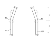
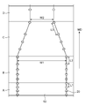
- FIGS. 2 and 3 are schematic plan views of the main part of the stretching apparatus in FIG.
- FIG. 2 is a schematic plan view of a portion of the rail that transitions from the MD stretching zone B to the TD contraction zone C in the stretching apparatus of FIG. 1.
- FIG. 3 is a schematic plan view of a portion of the rail that transitions from the TD contraction zone C to the release zone D in the stretching apparatus of FIG. 1.
- both ends of the tapered portion are bent portions 11 and 12 that bend at a predetermined angle ( ⁇ 1), respectively, thereby connecting to a straight portion having a constant rail-to-rail distance.
- the bending angle can be appropriately set according to a desired shrinkage rate and productivity.
- the bending angle ⁇ 1 can be, for example, 1 ° to 20 °.
- both side edges of the laminate are gripped by clips at the clip interval L1 in the transport direction (gripping process), and the laminate is passed through the straight portion.
- the clip interval in the conveying direction is expanded from L1 to L2 while being stretched and stretched in the longitudinal direction (MD stretching step), and the laminate is allowed to pass through the tapered portion and contracted in the width direction (TD shrinking step). May be included.
- 4 and 5 are each a schematic view showing an example of a shrinking / stretching process including these processes.
- each step in the shrinking / stretching step will be described in more detail with reference to these drawings.
- the left and right clips 20 grip both side edges of the laminate 50 taken into the stretching apparatus at a constant gripping interval (clip interval) and are guided by the left and right endless rails.
- the stacked body 50 is transported to the MD stretching zone B by the movement of each clip 20.
- the grip interval (clip interval) between both side edges in the grip zone A is typically equal to each other.
- the clip interval is the distance between the centers of adjacent clips.
- MD stretching step (MD stretching zone B)
- the laminate 50 held by the left and right clips 20 is transported in the longitudinal direction (MD stretching).
- MD stretching of the laminated body 50 is performed by gradually increasing the moving speed of the clip 20 in the transport direction and expanding the clip interval in the transport direction from L1 to L2.
- the draw ratio (L2 / L1) is controlled by adjusting the clip interval (grip interval in the grasping process) L1 at the entrance of the MD stretch zone B and the clip interval L2 in the transport direction at the exit of the MD stretch zone B. can do.
- the draw ratio (L2 / L1) in the MD stretching step is, for example, 1.1 times to 6.0 times, preferably 1.1 times to 5.5 times, more preferably 1.8 times to 3.0 times. .
- the draw ratio is less than 1.1 times, desired optical characteristics may not be obtained.
- the draw ratio exceeds 6.0 times, the laminate may break.
- the clip interval L1 is set to be equal to or less than an interval at which such unevenness is suppressed.
- the clip interval L1 is 60 mm or less, preferably 50 mm or less, more preferably 40 mm or less.
- L1 is 60 mm or less, preferably 50 mm or less, more preferably 40 mm or less.
- the occurrence of unevenness can be suppressed, and as a result, the width that is cut and removed by slit processing can be reduced.
- the clip interval L1 is set to be equal to or smaller than the predetermined interval as described above, the clip interval L2 after MD stretching also becomes small depending on the stretching ratio, and the clips 20 contact each other at the taper portion (particularly the bent portion). In some cases, interference occurs, and a desired shrinkage rate cannot be achieved (as a result, desired optical characteristics cannot be obtained). Therefore, the clip interval L2 is set to be equal to or greater than the interval at which the clips 20 do not interfere with each other when the stacked body 50 passes through the TD contraction zone C (particularly, the bent portion) that is a tapered portion. By setting it as such L2, L1 can be made small, without being restrict
- the clip interval L2 can be appropriately set according to the bending angle, the size / shape of the clip, and the like.
- the clip interval L2 is preferably 25 mm to 130 mm, and more preferably 35 mm to 50 mm. If the clip interval L2 is within the above range, in the TD contraction step, interference between the clips 20 in the taper portion (particularly the bent portion) can be avoided and a sufficient bending angle can be realized, and more uniform contraction can be realized. be able to. In addition, it is possible to avoid interference between clips even if the clip interval is small by increasing the bending radius (R) at the bent portion and bending it gently. However, in that case, it is necessary to form a rail around the circuit, and there is a problem that the equipment becomes large.
- the clip intervals L1 and L2 in the preferable range can be suitably achieved, and as a result, only the occurrence of unevenness can be suppressed. In addition, the problem of increasing the size of the equipment can be avoided.
- the stretching temperature of the laminate can be set to any appropriate value depending on the material for forming the thermoplastic resin substrate.
- the stretching temperature is typically at least the glass transition temperature (Tg) of the thermoplastic resin substrate, preferably the glass transition temperature (Tg) of the thermoplastic resin substrate + 10 ° C. or more, more preferably Tg + 15 ° C. or more.
- the stretching temperature of the laminate is preferably 170 ° C. or lower.
- the laminate 50 held by the left and right clips 20 is contracted in the width direction (TD contraction) while being conveyed in the longitudinal direction.
- the left and right endless rails 10R, 10L are tapered portions in which the distance between the rails continuously decreases. Done.
- the TD contraction rate can be controlled by adjusting the amount of change in the distance between rails. Specifically, the smaller the ratio of the distance between the rails at the outlet of the TD contraction zone C (end part on the release zone D) to the distance between the rails at the inlet of the TD contraction zone C (MD extension zone B side end), A large shrinkage rate is obtained.
- TD shrinkage ratio ((width of laminate at entrance of TD shrinkage zone C: W1) ⁇ (width of laminate at exit of TD shrinkage zone C: W2)) / (width of laminate at entrance of TD shrinkage zone C: W1) ⁇ 100) can be set to any appropriate value.
- the TD shrinkage ratio is preferably more than 15%, more preferably more than 20% and less than 50%. By setting such a shrinkage rate, more excellent optical characteristics can be obtained.
- the laminated body 50 is passed through the TD contraction zone C while maintaining the clip interval (L2) in the transport direction.
- the laminate 50 is contracted in the width direction and stretched in the longitudinal direction in the TD contraction step.
- the laminated body 50 is allowed to pass through the TD contraction zone C while increasing the clip interval in the transport direction from L2 to L3.
- the final stretching ratio can be increased by performing MD stretching in multiple stages.
- production of bending and a wrinkle can be suppressed can be acquired by performing TD shrinkage
- the draw ratio of the laminate after the TD shrinking process (the product of the draw ratio in the MD stretching process and the draw ratio in the TD shrinking process, also referred to as the final draw ratio.
- the final draw ratio when the TD shrinking process includes MD stretching is L3 / L1 and the final stretching ratio when the TD contraction step does not include MD stretching is L2 / L1), for example, 3.0 times or more, preferably 4 with respect to the original length of the laminate. 0.0 times or more.
- the temperature environment in the TD shrinking process can be the same as the stretching temperature in the MD stretching process.
- the clip 20 that holds the stacked body 50 is released.
- the distance between clips and the clip interval are both constant. If necessary, the clip is released after the laminate 50 is cooled to a desired temperature.
- the manufacturing method of the polarizing film of the present invention can include other steps in addition to the above.
- Examples of other processes include an insolubilization process, a dyeing process, a crosslinking process, a stretching process different from the above stretching process, a washing process, and a drying process (adjustment of moisture content).
- the other steps can be performed at any appropriate timing.
- the dyeing step is typically a step of dyeing the PVA resin layer with a dichroic substance.
- it is performed by adsorbing a dichroic substance to the PVA resin layer.
- adsorption method for example, a method of immersing a PVA resin layer (laminate) in a dye solution containing a dichroic substance, a method of applying a dye solution to the PVA resin layer, and a dye solution on a PVA resin layer The method of spraying etc. are mentioned.
- the laminate is immersed in a staining solution containing a dichroic substance. It is because a dichroic substance can adsorb
- both surfaces of the laminate may be immersed in the dyeing solution, or only one surface may be immersed.
- the dichroic substance examples include iodine and organic dyes. These may be used alone or in combination of two or more.
- the dichroic material is preferably iodine.
- the staining solution is preferably an iodine aqueous solution.
- the blending amount of iodine is preferably 0.1 to 1.0 part by weight with respect to 100 parts by weight of water. In order to increase the solubility of iodine in water, it is preferable to add an iodide salt to the aqueous iodine solution.
- Examples of the iodide salt include potassium iodide, lithium iodide, sodium iodide, zinc iodide, aluminum iodide, lead iodide, copper iodide, barium iodide, calcium iodide, tin iodide, and iodide.
- Examples include titanium. Among these, potassium iodide and sodium iodide are preferable.
- the blending amount of the iodide salt is preferably 0.3 to 15 parts by weight with respect to 100 parts by weight of water.
- the liquid temperature during staining of the staining liquid is preferably 20 ° C. to 40 ° C.
- the immersion time is preferably 5 seconds to 300 seconds. Under such conditions, the dichroic substance can be sufficiently adsorbed to the PVA resin layer.
- the insolubilization step and the crosslinking step are typically performed by immersing the PVA resin layer in an aqueous boric acid solution.
- the cleaning step is typically performed by immersing the PVA resin layer in an aqueous potassium iodide solution.
- the drying temperature in the drying step is preferably 30 ° C. to 100 ° C.
- the polarizing film produced by the above production method is substantially a PVA resin film in which a dichroic substance is adsorbed and oriented.
- the polarizing film preferably exhibits absorption dichroism at any wavelength of 380 nm to 780 nm.
- Arbitrary appropriate methods can be employ
- optical laminated body of this invention has the optical film (for example, polarizing film) manufactured with the manufacturing method of A term
- the base material may be provided on one side of the optical film via an adhesive layer, or may be directly laminated on the optical film without going through the adhesive layer.
- the optical laminate in the case where the optical film is a polarizing film has the polarizing film and a base material that is provided on at least one side of the polarizing film and can support the polarizing film.
- the base material the thermoplastic resin base material may be used as it is, or an optical functional film different from the thermoplastic resin base material may be used.
- the same material as the thermoplastic resin is used.
- (meth) acrylic resins, cellulose resins such as diacetylcellulose, triacetylcellulose, and the like are used.
- the optical functional film is preferably provided on one side of the polarizing film via an adhesive layer.
- the thickness of the optical functional film is preferably 20 ⁇ m to 100 ⁇ m.
- the thermoplastic resin base material previously provided on one side of the polarizing film is preferably peeled off in advance. This is because curling can be more reliably suppressed.
- the adhesive layer is formed of any appropriate adhesive. Examples of the adhesive include a polyvinyl alcohol-based adhesive.
- the optical laminate (polarizing film) of the present invention has a small shrinkage stress and can be excellent in dimensional stability even in a high temperature environment.
- the degree of polarization at a single transmittance of 41% is preferably 99.9% or more. Thus, it can be excellent in optical characteristics.
- Example 1 ⁇ Laminated body production process> An amorphous PET substrate (100 ⁇ m thick) was prepared as a thermoplastic resin substrate, and an aqueous PVA solution was applied to the amorphous PET substrate and dried at a temperature of 50 ° C. to 60 ° C. As a result, a PVA layer having a thickness of 14 ⁇ m was formed on the amorphous PET substrate to produce a laminate.
- the obtained laminate was subjected to MD stretching and TD shrinkage using a stretching apparatus as shown in FIG. Specifically, in the gripping zone A, the both side edges of the laminate are gripped and conveyed in the longitudinal direction at a clip interval L1: 35 mm, and in the MD stretching zone B, 1.43 times in the longitudinal direction at 140 ° C. The film was stretched in the air (clip interval L2 at the outlet of the MD stretching zone B: 50 mm).
- the TD contraction zone C 25% contraction was performed in the width direction, and at the same time, the film was stretched in the longitudinal direction (clip interval L3 at the exit of the TD contraction zone C: 105 mm, final stretching ratio: 3 times, width of the laminate: 650 mm). Thereafter, in the release zone D, the clip holding the laminate was released. In addition, although the bending angle of the bending part was about 7 degrees, the clip did not contact in the bending part.
- ⁇ Crosslinking treatment> The layered product after dyeing was immersed in a 60 ° C. boric acid aqueous solution (boric acid concentration: 5% by weight, potassium iodide concentration: 5% by weight) for 60 seconds, and further 1.8 times in the longitudinal direction in the boric acid aqueous solution. Stretched.
- Example 2 A polarizing film having a thickness of 4.0 ⁇ m was produced on a thermoplastic resin substrate in the same manner as in Example 1 except that the shrinkage / stretching process was performed as follows. ⁇ Shrinking / stretching process> In the gripping zone A, the both side edges of the laminate were gripped at a clip interval L1: 60 mm and conveyed in the longitudinal direction, and in the MD stretching zone B, the film was stretched in the air by 1.66 times in the longitudinal direction at 140 ° C. (MD Clip interval L2 at the exit of the stretching zone B: 100 mm).
- Example 1 A polarizing film having a thickness of 4.0 ⁇ m was produced on a thermoplastic resin substrate in the same manner as in Example 1 except that the shrinkage / stretching process was performed as follows. ⁇ Shrinking / stretching process> In the gripping zone A, the side edges of the laminate are gripped at a clip interval L1: 100 mm and conveyed in the longitudinal direction, and in the MD stretching zone B, air stretched 1.2 times in the longitudinal direction at 140 ° C. (MD Clip interval L2 at the exit of the stretching zone B: 120 mm).
- the TD contraction zone C 25% contraction was performed in the width direction, and at the same time, the film was stretched in the longitudinal direction (clip interval L3 at the outlet of the TD contraction zone C: 300 mm, final stretching ratio: 3 times, width of the laminate: 680 mm). Thereafter, in the release zone D, the clip holding the laminate was released. In addition, although the bending angle of the bending part was about 7 degrees, the clip did not contact in the bending part.
- Example 2 A polarizing film having a thickness of 4.0 ⁇ m was produced on a thermoplastic resin substrate in the same manner as in Example 1 except that the shrinkage / stretching process was performed as follows. ⁇ Shrinking / stretching process> In the gripping zone A, the both side edges of the laminate were gripped at a clip interval L1: 120 mm and conveyed in the longitudinal direction, and in the MD stretching zone B, the film was stretched in the air at 1.25 times in the longitudinal direction at 140 ° C. (MD Clip interval L2 at the exit of the stretching zone B: 150 mm).
- the TD contraction zone C 25% contraction was performed in the width direction, and at the same time, the film was stretched in the longitudinal direction (clip interval L3 at the exit of the TD contraction zone C: 360 mm, final stretching ratio: 3 times, width of the laminate: 650 mm). Thereafter, in the release zone D, the clip holding the laminate was released. In addition, although the bending angle of the bending part was about 7 degrees, the clip did not contact in the bending part.
- the width of the region where the unevenness of the optical characteristics occurs (hereinafter also referred to as “unstable region”) and L1
- the width of the unstable region was determined as follows. That is, the thickness distribution in the width direction was measured, and the region where the thickness distribution including the central portion was within 3 ⁇ m was defined as a stable region, and the other regions were defined as unstable regions.
- the production method of the present invention is suitably used for the production of optical films such as polarizing films and optical compensation films.
Landscapes
- Physics & Mathematics (AREA)
- Engineering & Computer Science (AREA)
- Mechanical Engineering (AREA)
- General Physics & Mathematics (AREA)
- Optics & Photonics (AREA)
- Shaping By String And By Release Of Stress In Plastics And The Like (AREA)
- Polarising Elements (AREA)
Abstract
本発明の光学フィルムの製造方法は、長尺状の樹脂基材を長手方向に搬送しながら該長手方向に延伸し、次いで、幅方向に収縮する工程(延伸・収縮工程)と、を含み、該延伸・収縮工程が、該長尺状の樹脂基材の把持手段としての複数のクリップを備えるテンター延伸装置を用いて該長尺状の樹脂基材の両側縁部を搬送方向のクリップ間隔L1で把持し、該クリップ間隔をL1からL2まで拡大することによって該長尺状の樹脂基材を長手方向に延伸し、次いで、幅方向のクリップ間隔を減少することによって該長尺状の樹脂基材を幅方向に収縮することを含む。該クリップ間隔L1が、60mm以下であり、該クリップ間隔L2が、幅方向のクリップ間隔を減少させる際にクリップ同士が干渉しない間隔である。
Description
本発明は、光学フィルムの製造方法に関する。
従来、長尺状のフィルムをテンタークリップによって把持および搬送し、該テンタークリップの搬送方向の間隔を広げることで延伸し、搬送方向と略直交する方向に該フィルムを収縮させて光学フィルムを作製する技術が知られている(特許文献1の請求項7)。このような延伸技術においては、延伸後のフィルム(例えば、フィルムの幅方向の端部領域)に光学特性のムラが生じるという問題がある。そのため、従来はムラが生じた領域をスリット加工等で切断除去し、ムラの無い領域のみを光学フィルムとして用いてきた。
一方、近年、ディスプレイの大型化の要望により、それに用いられる光学フィルムとして広幅のフィルムが求められる。そのため、上記スリット加工によって切断除去される領域はできるだけ小さいことが望ましい。
本発明は上記課題を解決するためになされたものであり、その主たる目的は、テンター延伸装置を用いて長尺状の樹脂フィルムを搬送方向に延伸および幅方向に収縮することを含む光学フィルムの製造方法であって、延伸後のフィルムに光学特性のムラが生じることを抑制し得る方法を提供することにある。
本発明は、長尺状の樹脂フィルムを長手方向に搬送しながら該長手方向に延伸し、次いで、幅方向に収縮する工程(延伸・収縮工程)を含む、光学フィルムの製造方法を提供する。該方法は、該延伸・収縮工程が、該長尺状の樹脂フィルムの把持手段としての複数のクリップを備えるテンター延伸装置を用いて該長尺状の樹脂フィルムの両側縁部を搬送方向のクリップ間隔L1で把持し、該クリップ間隔をL1からL2まで拡大することによって該長尺状の樹脂フィルムを長手方向に延伸し、次いで、幅方向のクリップ間隔を減少することによって該長尺状の樹脂フィルムを幅方向に収縮することを含み、該クリップ間隔L1が、60mm以下であり、該クリップ間隔L2が、幅方向のクリップ間隔を減少させる際にクリップ同士が干渉しない間隔である。
1つの実施形態においては、上記樹脂フィルムの長手方向への延伸倍率(L2/L1)が、1.1倍~6.0倍である。
1つの実施形態においては、上記延伸・収縮工程において、幅方向のクリップ間隔を減少することによって上記樹脂フィルムを幅方向に収縮する間に、搬送方向のクリップ間隔をL2からL3まで拡大することによって上記樹脂フィルムを長手方向に延伸する。
1つの実施形態においては、上記光学フィルムが、偏光膜である。
本発明の別の局面によれば、光学積層体が提供される。該光学積層体は、上記光学フィルムの製造方法により製造された光学フィルムと、該光学フィルムの少なくとも片側に設けられた基材と、を有する。
1つの実施形態においては、上記樹脂フィルムの長手方向への延伸倍率(L2/L1)が、1.1倍~6.0倍である。
1つの実施形態においては、上記延伸・収縮工程において、幅方向のクリップ間隔を減少することによって上記樹脂フィルムを幅方向に収縮する間に、搬送方向のクリップ間隔をL2からL3まで拡大することによって上記樹脂フィルムを長手方向に延伸する。
1つの実施形態においては、上記光学フィルムが、偏光膜である。
本発明の別の局面によれば、光学積層体が提供される。該光学積層体は、上記光学フィルムの製造方法により製造された光学フィルムと、該光学フィルムの少なくとも片側に設けられた基材と、を有する。
本発明の製造方法においては、長尺状の樹脂フィルムを把持するための複数のクリップを備えるテンター延伸装置を用いて、初期の搬送方向のクリップ間隔を所定の間隔以下として長手方向への延伸を行い、次いで、幅方向への収縮を行う。これにより、得られる光学フィルムに光学特性のムラが生じることを抑制して面内均一性を向上することができる。また、幅方向への収縮時におけるクリップ同士の干渉を回避することができる。
A.光学フィルムの製造方法
本発明の光学フィルムの製造方法は、長尺状の樹脂フィルムを長手方向に搬送しながら該長手方向に延伸し、次いで、幅方向に収縮する工程(延伸・収縮工程)を含む。該延伸・収縮工程は、該長尺状の樹脂フィルムの把持手段としての複数のクリップを備えるテンター延伸装置を用いて該長尺状の樹脂フィルムの両側縁部を搬送方向のクリップ間隔L1で把持し、該クリップ間隔をL1からL2まで拡大することによって該長尺状の樹脂フィルムを長手方向に延伸し、次いで、幅方向のクリップ間隔を減少することによって該長尺状の樹脂フィルムを幅方向に収縮することを含む。本発明の製造方法で用いられる長尺状の樹脂フィルムは、単層の樹脂フィルムであってもよく、二層以上の積層体であってもよい(例えば、後述する偏光膜の製造方法においては、熱可塑性樹脂基材とポリビニルアルコール系樹脂層との積層体が長尺状の樹脂フィルムに対応する)。
本発明の光学フィルムの製造方法は、長尺状の樹脂フィルムを長手方向に搬送しながら該長手方向に延伸し、次いで、幅方向に収縮する工程(延伸・収縮工程)を含む。該延伸・収縮工程は、該長尺状の樹脂フィルムの把持手段としての複数のクリップを備えるテンター延伸装置を用いて該長尺状の樹脂フィルムの両側縁部を搬送方向のクリップ間隔L1で把持し、該クリップ間隔をL1からL2まで拡大することによって該長尺状の樹脂フィルムを長手方向に延伸し、次いで、幅方向のクリップ間隔を減少することによって該長尺状の樹脂フィルムを幅方向に収縮することを含む。本発明の製造方法で用いられる長尺状の樹脂フィルムは、単層の樹脂フィルムであってもよく、二層以上の積層体であってもよい(例えば、後述する偏光膜の製造方法においては、熱可塑性樹脂基材とポリビニルアルコール系樹脂層との積層体が長尺状の樹脂フィルムに対応する)。
本発明の製造方法によって製造され得る光学フィルムとしては、上記延伸・収縮工程を含む製造方法によって製造され得る限りにおいて任意の適切な光学フィルムであり得る。係る光学フィルムの具体例としては、偏光膜、光学補償フィルム等が好ましく例示でき、偏光膜がより好ましく例示できる。以下、光学フィルムが偏光膜である実施形態(すなわち、偏光膜の製造方法)について説明するが、本発明の製造方法は当該実施形態に限定されない。
a.偏光膜の製造方法
本発明の偏光膜の製造方法は、熱可塑性樹脂基材上にポリビニルアルコール(以下、「PVA」と称する)系樹脂層を形成して積層体を作製する工程(積層体作製工程)と、該積層体を長手方向に搬送しながら該長手方向に延伸し、次いで、幅方向に収縮する工程(延伸・収縮工程)と、を含む。以下、各々の工程について説明する。
本発明の偏光膜の製造方法は、熱可塑性樹脂基材上にポリビニルアルコール(以下、「PVA」と称する)系樹脂層を形成して積層体を作製する工程(積層体作製工程)と、該積層体を長手方向に搬送しながら該長手方向に延伸し、次いで、幅方向に収縮する工程(延伸・収縮工程)と、を含む。以下、各々の工程について説明する。
a-1.積層体作製工程
積層体は、熱可塑性樹脂基材上にPVA系樹脂層を形成することにより作製される。熱可塑性樹脂基材は、PVA系樹脂層(得られる偏光膜)を片側から支持し得る限り、任意の適切な構成とされる。
積層体は、熱可塑性樹脂基材上にPVA系樹脂層を形成することにより作製される。熱可塑性樹脂基材は、PVA系樹脂層(得られる偏光膜)を片側から支持し得る限り、任意の適切な構成とされる。
熱可塑性樹脂基材の形成材料としては、例えば、ポリエチレンテレフタレート系樹脂等のエステル系樹脂、シクロオレフィン系樹脂、ポリプロピレン等のオレフィン系樹脂、ポリアミド系樹脂、ポリカーボネート系樹脂、これらの共重合体樹脂等が挙げられる。これらの中でも、好ましくは、シクロオレフィン系樹脂(例えば、ノルボルネン系樹脂)、非晶質のポリエチレンテレフタレート系樹脂である。非晶質のポリエチレンテレフタレート系樹脂の具体例としては、ジカルボン酸としてイソフタル酸をさらに含む共重合体や、グリコールとしてシクロヘキサンジメタノールをさらに含む共重合体が挙げられる。
熱可塑性樹脂基材の延伸方法は、任意の適切な方法を採用することができる。具体的には、固定端延伸でもよいし、自由端延伸でもよい。熱可塑性樹脂基材の延伸は、一段階で行ってもよいし、多段階で行ってもよい。多段階で行う場合、後述の熱可塑性樹脂基材の延伸倍率は、各段階の延伸倍率の積である。また、本工程における延伸方式は、特に限定されず、空中延伸方式でもよいし、水中延伸方式でもよい。
熱可塑性樹脂基材の延伸温度は、熱可塑性樹脂基材の形成材料、延伸方式等に応じて、任意の適切な値に設定することができる。延伸温度は、代表的には、熱可塑性樹脂基材のガラス転移温度(Tg)以上であり、好ましくはTg+10℃以上、さらに好ましくはTg+15℃~Tg+30℃である。延伸方式として水中延伸方式を採用し、熱可塑性樹脂基材の形成材料として非晶質のポリエチレンテレフタレート系樹脂を用いる場合、延伸温度を熱可塑性樹脂基材のガラス転移温度(例えば、60℃~100℃)より低くすることができる。
熱可塑性樹脂基材に、予め、表面改質処理(例えば、コロナ処理等)を施してもよいし、熱可塑性樹脂基材上に易接着層を形成してもよい。このような処理を行うことにより、熱可塑性樹脂基材とPVA系樹脂層との密着性を向上させることができる。なお、表面改質処理および/または易接着層の形成は、上記延伸前に行ってもよいし、上記延伸後に行ってもよい。
上記PVA系樹脂層の形成方法は、任意の適切な方法を採用することができる。好ましくは、延伸処理が施された熱可塑性樹脂基材上に、PVA系樹脂を含む塗布液を塗布し、乾燥することにより、PVA系樹脂層を形成する。
上記PVA系樹脂としては、任意の適切な樹脂を用いることができる。例えば、ポリビニルアルコール、エチレン-ビニルアルコール共重合体が挙げられる。ポリビニルアルコールは、ポリ酢酸ビニルをケン化することにより得られる。エチレン-ビニルアルコール共重合体は、エチレン-酢酸ビニル共重合体をケン化することにより得られる。PVA系樹脂のケン化度は、通常85モル%~100モル%であり、好ましくは95.0モル%~99.95モル%、さらに好ましくは99.0モル%~99.93モル%である。ケン化度は、JIS K 6726-1994に準じて求めることができる。このようなケン化度のPVA系樹脂を用いることによって、耐久性に優れた偏光膜を得ることができる。ケン化度が高すぎる場合には、塗布液がゲル化しやすく、均一な塗布膜を形成することが困難となるおそれがある。
PVA系樹脂の平均重合度は、目的に応じて適切に選択し得る。平均重合度は、通常1000~10000であり、好ましくは1200~4500、さらに好ましくは1500~4300である。なお、平均重合度は、JIS K 6726-1994に準じて求めることができる。
上記塗布液は、代表的には、上記PVA系樹脂を溶媒に溶解させた溶液である。溶媒としては、例えば、水、ジメチルスルホキシド、ジメチルホルムアミド、ジメチルアセトアミドN-メチルピロリドン、各種グリコール類、トリメチロールプロパン等の多価アルコール類、エチレンジアミン、ジエチレントリアミン等のアミン類が挙げられる。これらは単独で、または、二種以上組み合わせて用いることができる。これらの中でも、好ましくは、水である。溶液のPVA系樹脂濃度は、溶媒100重量部に対して、好ましくは3重量部~20重量部である。このような樹脂濃度であれば、熱可塑性樹脂基材に密着した均一な塗布膜を形成することができる。
塗布液に、添加剤を配合してもよい。添加剤としては、例えば、可塑剤、界面活性剤等が挙げられる。可塑剤としては、例えば、エチレングリコールやグリセリン等の多価アルコールが挙げられる。界面活性剤としては、例えば、非イオン界面活性剤が挙げられる。これらは、得られるPVA系樹脂層の均一性や染色性、延伸性をより一層向上させる目的で使用し得る。
塗布液の塗布方法としては、任意の適切な方法を採用することができる。例えば、ロールコート法、スピンコート法、ワイヤーバーコート法、ディップコート法、ダイコート法、カーテンコート法、スプレコート法、ナイフコート法(コンマコート法等)等が挙げられる。
上記乾燥温度は、熱可塑性樹脂基材のガラス転移温度(Tg)以下であることが好ましく、さらに好ましくはTg-20℃以下である。このような温度で乾燥することにより、PVA系樹脂層を形成する前に熱可塑性樹脂基材が変形するのを防止して、得られるPVA系樹脂層の配向性が悪化するのを防止することができる。こうして、熱可塑性樹脂基材がPVA系樹脂層とともに良好に変形し得、後述の積層体の収縮および延伸を良好に行うことができる。その結果、PVA系樹脂層に良好な配向性を付与することができ、優れた光学特性を有する偏光膜を得ることができる。ここで、「配向性」とは、PVA系樹脂層の分子鎖の配向を意味する。
a-2.収縮・延伸工程
次に、上記積層体を長手方向に搬送しながら該長手方向に延伸し、次いで、幅方向に収縮する。なお、延伸方向である長手方向が、実質的に、得られる偏光膜の吸収軸方向となる。
次に、上記積層体を長手方向に搬送しながら該長手方向に延伸し、次いで、幅方向に収縮する。なお、延伸方向である長手方向が、実質的に、得られる偏光膜の吸収軸方向となる。
本発明においては、上記積層体の延伸および収縮を、積層体の把持手段としての複数のクリップを備えるテンター延伸装置を用いて積層体の両側縁部を搬送方向のクリップ間隔L1で把持し、該クリップ間隔をL1からL2まで拡大することによって積層体を長手方向に延伸し、次いで、幅方向のクリップ間隔を減少することによって積層体を幅方向に収縮することによって行う。幅方向のクリップ間隔を減少することによって積層体を幅方向に収縮する間に、搬送方向のクリップ間隔をL2からL3まで拡大することによって積層体を長手方向に延伸してもよい。なお、クリップ間隔L1は、60mm以下であり、クリップ間隔L2は、幅方向のクリップ間隔を減少させる際にクリップ同士が干渉しない間隔である。
上記テンター延伸装置としては、例えば、レール間距離が一定である直線部とレール間距離が連続的に減少するテーパー部とを有する一対のレールと、各レール上をクリップ間隔を変化させながら走行可能な複数のクリップと、を備える延伸装置が用いられ得る。このような延伸装置によれば、積層体の両側縁部をクリップで把持した状態で、搬送方向のクリップ間隔(同一レール上のクリップ間距離)および幅方向のクリップ間隔(異なるレール上のクリップ間距離)を変化させることによって、積層体の延伸および収縮が可能となる。
図1は、本発明の製造方法に用いられ得る延伸装置の一例の全体構成を説明する概略平面図である。図1を参照しながら、本発明の製造方法に用いられ得る延伸装置について説明する。延伸装置100は、平面視で、左右両側に、無端レール10Lと無端レール10Rとを左右対称に有する。なお、本明細書においては、積層体の入口側から見て左側の無端レールを左側の無端レール10L、右側の無端レールを右側の無端レール10Rと称する。左右の無端レール10L、10R上にはそれぞれ、積層体把持用の多数のクリップ20が配置されている。クリップ20は、それぞれのレールに案内されてループ状に巡回移動する。左側の無端レール10L上のクリップ20は反時計廻り方向に巡回移動し、右側の無端レール10R上のクリップ20は時計廻り方向に巡回移動する。延伸装置においては、積層体の搬入側から搬出側へ向けて、把持ゾーンA、MD延伸ゾーンB、TD収縮ゾーンC、および解放ゾーンDが順に設けられている。なお、これらのそれぞれのゾーンは、積層体が実質的に把持、MD延伸、TD収縮(またはTD収縮とMD延伸)および解放されるゾーンを意味し、機械的、構造的に独立した区画を意味するものではない。また、図1の延伸装置におけるそれぞれのゾーンの長さの比率は、実際の長さの比率と異なることに留意されたい。
把持ゾーンAおよびMD延伸ゾーンBでは、左右の無端レール10R、10Lは、レール間距離が一定である直線部とされている。代表的には、左右の無端レール10R、10Lは、処理対象となる積層体の初期幅に対応するレール間距離で互いに略平行となるよう構成されている。TD収縮ゾーンCでは、左右の無端レール10R、10Lは、レール間距離が連続的に減少するテーパー部とされている。代表的には、左右の無端レール10R、10Lは、MD延伸ゾーンB側から解放ゾーンD側に向かうに従ってレール間距離が上記積層体の収縮後の幅に対応するまで徐々に減少する構成とされている。解放ゾーンDでは、左右の無端レール10R、10Lは、レール間距離が一定である直線部とされており、代表的には、上記積層体の収縮後の幅に対応するレール間距離で互いに略平行となるよう構成されている。
左側の無端レール10L上のクリップ(左側のクリップ)20および右側の無端レール10R上のクリップ(右側のクリップ)20は、それぞれ独立して巡回移動し得る。例えば、左側の無端レール10Lの駆動用スプロケット30a、30bが電動モータ40a、40bによって反時計廻り方向に回転駆動され、右側の無端レール10Rの駆動用スプロケット30a、30bが電動モータ40a、40bによって時計廻り方向に回転駆動される。その結果、これら駆動用スプロケット30a、30bに係合している駆動ローラ(図示せず)のクリップ担持部材(図示せず)に走行力が与えられる。これにより、左側のクリップ20は反時計廻り方向に巡回移動し、右側のクリップ20は時計廻り方向に巡回移動する。左側の電動モータおよび右側の電動モータを、それぞれ独立して駆動させることにより、左側のクリップ20および右側のクリップ20をそれぞれ独立して巡回移動させることができる。
クリップサイズは、好ましくは12mm~40mmであり、より好ましくは15mm~35mmである。クリップサイズが12mm未満である場合には、延伸張力を保持できなくなって破断したり、クリップ搬送部の強度不足により駆動不具合が発生する場合がある。クリップサイズが40mmを超えると、クリップ近傍で延伸されない領域が大きくなり端部のムラが発生したり、非把持部が局所的に延伸されることで樹脂フィルムの表面に割れが発生する場合がある。なお、クリップサイズとは、把持領域の幅を意味する。
さらに、左側のクリップ20および右側のクリップ20は、それぞれ可変ピッチ型である。すなわち、左右のクリップ20、20は、それぞれ独立して、移動に伴って搬送方向(MD)のクリップ間隔(クリップピッチ)が変化し得る。可変ピッチ型のクリップは、特開2008-23775号公報に記載の構成等の任意の適切な構成により実現され得る。
図2および図3はそれぞれ、図1の延伸装置の要部概略平面図である。図2は、図1の延伸装置において、MD延伸ゾーンBからTD収縮ゾーンCへ移行する部分のレールの概略平面図である。図3は、図1の延伸装置において、TD収縮ゾーンCから解放ゾーンDへ移行する部分のレールの概略平面図である。図2および図3に示されるように、テーパー部の両端はそれぞれ、所定の角度(θ1)で屈曲する屈曲部11、12とされ、これにより、レール間距離が一定である直線部との接続が可能とされている。屈曲角度は、所望の収縮率および生産性に応じて適切に設定され得る。屈曲角度θ1は、例えば1°~20°であり得る。
図1に例示したような延伸装置を用いる場合、収縮・延伸工程は、積層体の両側縁部をクリップによって搬送方向のクリップ間隔L1で把持すること(把持工程)、積層体を直線部を通過させながら搬送方向のクリップ間隔をL1からL2まで拡大して、長手方向に延伸すること(MD延伸工程)、積層体をテーパー部を通過させて、幅方向に収縮すること(TD収縮工程)を含み得る。必要に応じて、積層体を把持するクリップを解放すること(解放工程)をさらに含んでもよい。図4および図5はそれぞれ、これらの工程を含む収縮・延伸工程の一例を示す概略図である。以下、これらの図を参照しながら収縮・延伸工程における各工程についてより詳細に説明する。
まず、把持工程(把持ゾーンA)において、左右のクリップ20によって、延伸装置に取り込まれた積層体50の両側縁部を一定の把持間隔(クリップ間隔)で把持し、左右の無端レールに案内された各クリップ20の移動により、当該積層体50をMD延伸ゾーンBに搬送する。把持ゾーンAにおける両側縁部の把持間隔(クリップ間隔)は、代表的には互いに等しい間隔とされる。なお、クリップ間隔とは、隣り合うクリップの中心間の距離である。
次いで、MD延伸工程(MD延伸ゾーンB)において、左右のクリップ20で把持された積層体50を搬送しながら、長手方向に延伸(MD延伸)する。積層体50のMD延伸は、クリップ20の搬送方向への移動速度を徐々に増大させ、搬送方向のクリップ間隔をL1からL2まで拡大することにより行われる。MD延伸ゾーンBの入口における搬送方向のクリップ間隔(把持工程における把持間隔)L1とMD延伸ゾーンBの出口における搬送方向のクリップ間隔L2とを調整することにより、延伸倍率(L2/L1)を制御することができる。
MD延伸工程における延伸倍率(L2/L1)は、例えば1.1倍~6.0倍、好ましくは1.1倍~5.5倍、より好ましくは1.8倍~3.0倍である。延伸倍率が1.1倍未満であると、所望の光学特性が得られない場がある。一方、延伸倍率が6.0倍を超えると、積層体が破断する場合がある。
ここで、クリップ間隔L1が大き過ぎると、積層体50のクリップ20で把持されない部分に幅方向に収縮するような応力が発生し、その結果、得られる偏光膜の光学特性(例えば、偏光特性)にムラが生じると推測される。よって、本発明の特徴の1つとして、クリップ間隔L1はこのようなムラの発生が抑制される間隔以下に設定される。
具体的には、クリップ間隔L1は、60mm以下であり、好ましくは50mm以下、より好ましくは40mm以下である。L1を60mm以下とすることでムラの発生を抑制することができ、その結果、スリット加工によって切断除去される幅を小さくすることができる。L1の下限としては、延伸後に後述のクリップ間隔L2を達成できる限りにおいて制限はなく、例えば25mm以上であり得る。
一方、上記のようにクリップ間隔L1を所定の間隔以下とすると、延伸倍率に依ってはMD延伸後のクリップ間隔L2も小さくなり、テーパー部(特に、屈曲部)においてクリップ20同士が接触等の干渉を生じ、所望の収縮率が達成できない(結果として、所望の光学特性が得られない)場合がある。よって、クリップ間隔L2は、テーパー部とされているTD収縮ゾーンC(特に、屈曲部)を積層体50が通過する際にクリップ20同士が干渉しない間隔以上にされる。このようなL2とすることで、L1は屈曲部でクリップ同士が干渉しない間隔に制限されることなく小さくすることができる。なお、「クリップ同士が干渉しない」とは、クリップおよびその担持部材や間隔調整機構が互いに接触することなく、クリップが設定どおりに屈曲部を移動可能であることを意味する。
クリップ間隔L2は、屈曲角度、クリップのサイズ・形状等に応じて適切に設定され得る。クリップ間隔L2は、好ましくは25mm~130mmであり、より好ましくは35mm~50mmである。クリップ間隔L2が上記範囲内であれば、TD収縮工程において、テーパー部(特に、屈曲部)におけるクリップ20同士の干渉を回避して十分な屈曲角度を実現できるとともに、より均一な収縮を実現することができる。なお、屈曲部における屈曲半径(R)を大きくして緩やかに屈曲させることで、クリップ間隔が小さくてもクリップ同士の干渉を回避することが可能である。しかしながら、その場合には、大回りにレールを形成する必要があり、設備が大型化するという問題がある。これに対し、本発明においては、TD収縮がMD延伸後に行われることから、上記好ましい範囲のクリップ間隔L1とL2とを好適に両立することができ、その結果、ムラの発生を抑制するだけでなく、上記設備の大型化の問題を回避することもできる。
積層体の延伸温度は、熱可塑性樹脂基材の形成材料等に応じて、任意の適切な値に設定することができる。延伸温度は、代表的には熱可塑性樹脂基材のガラス転移温度(Tg)以上であり、好ましくは熱可塑性樹脂基材のガラス転移温度(Tg)+10℃以上、さらに好ましくはTg+15℃以上である。その一方で、積層体の延伸温度は、好ましくは170℃以下である。このような温度で延伸することで、PVA系樹脂の結晶化が急速に進むのを抑制して、当該結晶化による不具合(例えば、延伸によるPVA系樹脂層の配向を妨げる)を抑制することができる。
次いで、TD収縮工程(TD収縮ゾーンC)において、左右のクリップ20で把持された積層体50を長手方向へ搬送しながら、幅方向へ収縮(TD収縮)する。TD収縮ゾーンCにおいては、左右の無端レール10R、10Lがレール間距離が連続的に減少するテーパー部とされているので、当該ゾーンを通過させることによって、積層体50の幅方向への収縮が行われる。TD収縮率は、レール間距離の変化量を調整することによって制御することができる。具体的には、TD収縮ゾーンCの入口(MD延伸ゾーンB側端部)におけるレール間距離に対するTD収縮ゾーンCの出口(解放ゾーンD側端部)におけるレール間距離の比を小さくするほど、大きい収縮率が得られる。
TD収縮率((TD収縮ゾーンCの入口における積層体の幅:W1)-(TD収縮ゾーンCの出口における積層体の幅:W2))/(TD収縮ゾーンCの入口における積層体の幅:W1)×100)は、任意の適切な値に設定することができる。TD収縮率は、好ましくは15%を超え、さらに好ましくは20%を超え50%未満である。このような収縮率とすることにより、より優れた光学特性を得ることができる。
図4に例示する実施形態においては、TD収縮工程において、積層体50の幅方向への収縮のみが行なわれる。この場合、搬送方向のクリップ間隔(L2)を維持したままで、積層体50をTD収縮ゾーンCを通過させる。一方、図5に例示する実施形態においては、TD収縮工程において、積層体50の幅方向への収縮と長手方向への延伸とが行なわれる。この場合、搬送方向のクリップ間隔をL2からL3まで拡大しながら、積層体50をTD収縮ゾーンCを通過させる。MD延伸工程とTD収縮工程とにおいて、多段階でMD延伸を行うことにより最終延伸倍率を高くすることができる。また、TD収縮とMD延伸とを同時に行うことにより、撓みやシワの発生を抑制することができるという効果が得られ得る。
TD収縮工程後における積層体の延伸倍率(MD延伸工程における延伸倍率とTD収縮工程における延伸倍率との積であり、最終延伸倍率とも称する。TD収縮工程がMD延伸を含む場合の最終延伸倍率は、L3/L1であり、TD収縮工程がMD延伸を含まない場合の最終延伸倍率は、L2/L1である)は、積層体の元長に対して、例えば3.0倍以上、好ましくは4.0倍以上である。このような高い倍率で延伸することにより、優れた光学特性を有する偏光膜を得ることができる。
TD収縮工程における温度環境は、MD延伸工程における延伸温度と同様であり得る。
最後に、解放工程(解放ゾーンD)において、積層体50を把持するクリップ20を解放する。解放工程においては、代表的には、クリップ間距離およびクリップ間隔がいずれも一定とされる。必要に応じて、積層体50を所望の温度に冷却した後にクリップを解放する。
a-3.その他の工程
本発明の偏光膜の製造方法は、上記以外に、その他の工程を含み得る。その他の工程としては、例えば、不溶化工程、染色工程、架橋工程、上記延伸とは別の延伸工程、洗浄工程、乾燥(水分率の調節)工程等が挙げられる。その他の工程は、任意の適切なタイミングで行い得る。
本発明の偏光膜の製造方法は、上記以外に、その他の工程を含み得る。その他の工程としては、例えば、不溶化工程、染色工程、架橋工程、上記延伸とは別の延伸工程、洗浄工程、乾燥(水分率の調節)工程等が挙げられる。その他の工程は、任意の適切なタイミングで行い得る。
上記染色工程は、代表的には、PVA系樹脂層を二色性物質で染色する工程である。好ましくは、PVA系樹脂層に二色性物質を吸着させることにより行う。当該吸着方法としては、例えば、二色性物質を含む染色液にPVA系樹脂層(積層体)を浸漬させる方法、PVA系樹脂層に染色液を塗布する方法、PVA系樹脂層に染色液を噴霧する方法等が挙げられる。好ましくは、二色性物質を含む染色液に積層体を浸漬させる方法である。二色性物質が良好に吸着し得るからである。なお、積層体両面を染色液に浸漬させてもよいし、片面のみ浸漬させてもよい。
上記二色性物質としては、例えば、ヨウ素、有機染料が挙げられる。これらは単独で、または、二種以上組み合わせて用いることができる。二色性物質は、好ましくは、ヨウ素である。二色性物質としてヨウ素を用いる場合、上記染色液は、好ましくは、ヨウ素水溶液である。ヨウ素の配合量は、水100重量部に対して、好ましくは0.1重量部~1.0重量部である。ヨウ素の水に対する溶解性を高めるため、ヨウ素水溶液にヨウ化物塩を配合することが好ましい。ヨウ化物塩としては、例えば、ヨウ化カリウム、ヨウ化リチウム、ヨウ化ナトリウム、ヨウ化亜鉛、ヨウ化アルミニウム、ヨウ化鉛、ヨウ化銅、ヨウ化バリウム、ヨウ化カルシウム、ヨウ化錫、ヨウ化チタン等が挙げられる。これらの中でも、好ましくは、ヨウ化カリウム、ヨウ化ナトリウムである。ヨウ化物塩の配合量は、水100重量部に対して、好ましくは0.3重量部~15重量部である。
染色液の染色時の液温は、好ましくは20℃~40℃である。染色液にPVA系樹脂層を浸漬させる場合、浸漬時間は、好ましくは5秒~300秒である。このような条件であれば、PVA系樹脂層に十分に二色性物質を吸着させることができる。
上記不溶化工程および架橋工程は、代表的には、ホウ酸水溶液にPVA系樹脂層を浸漬させることにより行う。上記洗浄工程は、代表的には、ヨウ化カリウム水溶液にPVA系樹脂層を浸漬させることにより行う。上記乾燥工程における乾燥温度は、好ましくは30℃~100℃である。
B.偏光膜
上記製造方法により作製される偏光膜は、実質的には、二色性物質を吸着配向させたPVA系樹脂膜である。偏光膜は、好ましくは、波長380nm~780nmのいずれかの波長で吸収二色性を示す。
上記製造方法により作製される偏光膜は、実質的には、二色性物質を吸着配向させたPVA系樹脂膜である。偏光膜は、好ましくは、波長380nm~780nmのいずれかの波長で吸収二色性を示す。
偏光膜の使用方法は、任意の適切な方法が採用され得る。具体的には、上記熱可塑性樹脂基材と一体となった状態で使用してもよいし、熱可塑性樹脂基材から他の部材に転写して(熱可塑性樹脂基材を剥離して)使用してもよい。
C.光学積層体
本発明の光学積層体は、A項に記載の製造方法により製造された光学フィルム(例えば、偏光膜)と、該光学フィルムの少なくとも片側に設けられた基材とを有する。基材は、接着剤層を介して光学フィルムの片側に設けられていてもよく、接着剤層を介することなく直接光学フィルムに積層されていてもよい。
本発明の光学積層体は、A項に記載の製造方法により製造された光学フィルム(例えば、偏光膜)と、該光学フィルムの少なくとも片側に設けられた基材とを有する。基材は、接着剤層を介して光学フィルムの片側に設けられていてもよく、接着剤層を介することなく直接光学フィルムに積層されていてもよい。
光学フィルムが偏光膜である場合の光学積層体は、上記偏光膜と、偏光膜の少なくとも片側に設けられ、偏光膜を支持し得る基材とを有する。この基材としては、上記熱可塑性樹脂基材をそのまま用いてもよいし、上記熱可塑性樹脂基材とは別の光学機能フィルムを用いてもよい。光学機能フィルムの形成材料としては、例えば、上記熱可塑性樹脂と同様の材料が用いられる。これら以外にも、例えば、(メタ)アクリル系樹脂、ジアセチルセルロース、トリアセチルセルロース等のセルロース系樹脂等が用いられる。
光学機能フィルムは、好ましくは、接着剤層を介して偏光膜の片側に設けられる。光学機能フィルムを設けることにより、カールを抑制することができる。光学機能フィルムの厚みは、好ましくは20μm~100μmである。光学機能フィルムを用いる場合、予め、偏光膜の片側に設けられている熱可塑性樹脂基材は、好ましくは、剥離される。カールをより確実に抑制できるからである。接着剤層は、任意の適切な接着剤で形成される。接着剤としては、例えば、ポリビニルアルコール系接着剤が挙げられる。
本発明の光学積層体(偏光膜)は、収縮応力が小さく、高温環境下でも寸法安定性に優れ得る。また、単体透過率41%における偏光度は、好ましくは99.9%以上である。このように光学特性に優れ得る。
以下、実施例によって本発明を具体的に説明するが、本発明はこれら実施例によって限定されるものではない。
[実施例1]
<積層体作製工程>
熱可塑性樹脂基材として、非晶性PET基材(100μm厚)を準備し、該非晶性PET基材にPVA水溶液を塗布し、50℃~60℃の温度で乾燥した。これにより、非晶性PET基材上に14μm厚のPVA層を製膜し、積層体を作製した。
<積層体作製工程>
熱可塑性樹脂基材として、非晶性PET基材(100μm厚)を準備し、該非晶性PET基材にPVA水溶液を塗布し、50℃~60℃の温度で乾燥した。これにより、非晶性PET基材上に14μm厚のPVA層を製膜し、積層体を作製した。
<収縮・延伸工程>
得られた積層体を、図1に示すような延伸装置を用いて、MD延伸およびTD収縮した。具体的には、把持ゾーンAにおいて、クリップ間隔L1:35mmで積層体の両側縁部を把持して長手方向に搬送し、MD延伸ゾーンBにおいて、140℃で、長手方向に1.43倍に空中延伸した(MD延伸ゾーンBの出口におけるクリップ間隔L2:50mm)。次いで、TD収縮ゾーンCにおいて、幅方向に25%収縮させると同時に、長手方向に空中延伸した(TD収縮ゾーンCの出口におけるクリップ間隔L3:105mm、最終延伸倍率:3倍、積層体の幅:650mm)。その後、解放ゾーンDにおいて、積層体を把持するクリップを解放した。なお、屈曲部の屈曲角度は約7°であったが、屈曲部においてクリップの接触は生じなかった。
得られた積層体を、図1に示すような延伸装置を用いて、MD延伸およびTD収縮した。具体的には、把持ゾーンAにおいて、クリップ間隔L1:35mmで積層体の両側縁部を把持して長手方向に搬送し、MD延伸ゾーンBにおいて、140℃で、長手方向に1.43倍に空中延伸した(MD延伸ゾーンBの出口におけるクリップ間隔L2:50mm)。次いで、TD収縮ゾーンCにおいて、幅方向に25%収縮させると同時に、長手方向に空中延伸した(TD収縮ゾーンCの出口におけるクリップ間隔L3:105mm、最終延伸倍率:3倍、積層体の幅:650mm)。その後、解放ゾーンDにおいて、積層体を把持するクリップを解放した。なお、屈曲部の屈曲角度は約7°であったが、屈曲部においてクリップの接触は生じなかった。
<染色処理>
次いで、積層体を、25℃のヨウ素水溶液(ヨウ素濃度:0.5重量%、ヨウ化カリウム濃度:10重量%)に30秒間浸漬させた。
次いで、積層体を、25℃のヨウ素水溶液(ヨウ素濃度:0.5重量%、ヨウ化カリウム濃度:10重量%)に30秒間浸漬させた。
<架橋処理>
染色後の積層体を、60℃のホウ酸水溶液(ホウ酸濃度:5重量%、ヨウ化カリウム濃度:5重量%)に60秒間浸漬させ、該ホウ酸水溶液中でさらに1.8倍長手方向に延伸した。
染色後の積層体を、60℃のホウ酸水溶液(ホウ酸濃度:5重量%、ヨウ化カリウム濃度:5重量%)に60秒間浸漬させ、該ホウ酸水溶液中でさらに1.8倍長手方向に延伸した。
<洗浄処理>
架橋処理後、積層体を、25℃のヨウ化カリウム水溶液(ヨウ化カリウム濃度:5重量%)に5秒間浸漬させた。
このようにして、熱可塑性樹脂基材上に、厚み4.0μmの偏光膜を作製した。
架橋処理後、積層体を、25℃のヨウ化カリウム水溶液(ヨウ化カリウム濃度:5重量%)に5秒間浸漬させた。
このようにして、熱可塑性樹脂基材上に、厚み4.0μmの偏光膜を作製した。
[実施例2]
以下のようにして収縮・延伸工程を行ったこと以外は実施例1と同様にして、熱可塑性樹脂基材上に、厚み4.0μmの偏光膜を作製した。
<収縮・延伸工程>
把持ゾーンAにおいて、クリップ間隔L1:60mmで積層体の両側縁部を把持して長手方向に搬送し、MD延伸ゾーンBにおいて、140℃で、長手方向に1.66倍に空中延伸した(MD延伸ゾーンBの出口におけるクリップ間隔L2:100mm)。次いで、TD収縮ゾーンCにおいて、幅方向に25%収縮させると同時に、長手方向に空中延伸した(TD収縮ゾーンCの出口におけるクリップ間隔L3:180mm、最終延伸倍率:3倍、積層体の幅:700mm)。その後、解放ゾーンDにおいて、積層体を把持するクリップを解放した。なお、屈曲部の屈曲角度は約7°であったが、屈曲部においてクリップの接触は生じなかった。
以下のようにして収縮・延伸工程を行ったこと以外は実施例1と同様にして、熱可塑性樹脂基材上に、厚み4.0μmの偏光膜を作製した。
<収縮・延伸工程>
把持ゾーンAにおいて、クリップ間隔L1:60mmで積層体の両側縁部を把持して長手方向に搬送し、MD延伸ゾーンBにおいて、140℃で、長手方向に1.66倍に空中延伸した(MD延伸ゾーンBの出口におけるクリップ間隔L2:100mm)。次いで、TD収縮ゾーンCにおいて、幅方向に25%収縮させると同時に、長手方向に空中延伸した(TD収縮ゾーンCの出口におけるクリップ間隔L3:180mm、最終延伸倍率:3倍、積層体の幅:700mm)。その後、解放ゾーンDにおいて、積層体を把持するクリップを解放した。なお、屈曲部の屈曲角度は約7°であったが、屈曲部においてクリップの接触は生じなかった。
[比較例1]
以下のようにして収縮・延伸工程を行ったこと以外は実施例1と同様にして、熱可塑性樹脂基材上に、厚み4.0μmの偏光膜を作製した。
<収縮・延伸工程>
把持ゾーンAにおいて、クリップ間隔L1:100mmで積層体の両側縁部を把持して長手方向に搬送し、MD延伸ゾーンBにおいて、140℃で、長手方向に1.2倍に空中延伸した(MD延伸ゾーンBの出口におけるクリップ間隔L2:120mm)。次いで、TD収縮ゾーンCにおいて、幅方向に25%収縮させると同時に、長手方向に空中延伸した(TD収縮ゾーンCの出口におけるクリップ間隔L3:300mm、最終延伸倍率:3倍、積層体の幅:680mm)。その後、解放ゾーンDにおいて、積層体を把持するクリップを解放した。なお、屈曲部の屈曲角度は約7°であったが、屈曲部においてクリップの接触は生じなかった。
以下のようにして収縮・延伸工程を行ったこと以外は実施例1と同様にして、熱可塑性樹脂基材上に、厚み4.0μmの偏光膜を作製した。
<収縮・延伸工程>
把持ゾーンAにおいて、クリップ間隔L1:100mmで積層体の両側縁部を把持して長手方向に搬送し、MD延伸ゾーンBにおいて、140℃で、長手方向に1.2倍に空中延伸した(MD延伸ゾーンBの出口におけるクリップ間隔L2:120mm)。次いで、TD収縮ゾーンCにおいて、幅方向に25%収縮させると同時に、長手方向に空中延伸した(TD収縮ゾーンCの出口におけるクリップ間隔L3:300mm、最終延伸倍率:3倍、積層体の幅:680mm)。その後、解放ゾーンDにおいて、積層体を把持するクリップを解放した。なお、屈曲部の屈曲角度は約7°であったが、屈曲部においてクリップの接触は生じなかった。
[比較例2]
以下のようにして収縮・延伸工程を行ったこと以外は実施例1と同様にして、熱可塑性樹脂基材上に、厚み4.0μmの偏光膜を作製した。
<収縮・延伸工程>
把持ゾーンAにおいて、クリップ間隔L1:120mmで積層体の両側縁部を把持して長手方向に搬送し、MD延伸ゾーンBにおいて、140℃で、長手方向に1.25倍に空中延伸した(MD延伸ゾーンBの出口におけるクリップ間隔L2:150mm)。次いで、TD収縮ゾーンCにおいて、幅方向に25%収縮させると同時に、長手方向に空中延伸した(TD収縮ゾーンCの出口におけるクリップ間隔L3:360mm、最終延伸倍率:3倍、積層体の幅:650mm)。その後、解放ゾーンDにおいて、積層体を把持するクリップを解放した。なお、屈曲部の屈曲角度は約7°であったが、屈曲部においてクリップの接触は生じなかった。
以下のようにして収縮・延伸工程を行ったこと以外は実施例1と同様にして、熱可塑性樹脂基材上に、厚み4.0μmの偏光膜を作製した。
<収縮・延伸工程>
把持ゾーンAにおいて、クリップ間隔L1:120mmで積層体の両側縁部を把持して長手方向に搬送し、MD延伸ゾーンBにおいて、140℃で、長手方向に1.25倍に空中延伸した(MD延伸ゾーンBの出口におけるクリップ間隔L2:150mm)。次いで、TD収縮ゾーンCにおいて、幅方向に25%収縮させると同時に、長手方向に空中延伸した(TD収縮ゾーンCの出口におけるクリップ間隔L3:360mm、最終延伸倍率:3倍、積層体の幅:650mm)。その後、解放ゾーンDにおいて、積層体を把持するクリップを解放した。なお、屈曲部の屈曲角度は約7°であったが、屈曲部においてクリップの接触は生じなかった。
上記実施例および比較例で得られた延伸フィルム(すなわち、染色処理に供する前のフィルム)に関して、光学特性のムラが生じた領域(以下、「不安定領域」とも称する)の幅とL1との関係を図6に示す。なお、不安定領域の幅は以下のようにして求めた。すなわち、幅方向の厚み分布を測定し、中央部を含む厚み分布が3μmに収まる領域を安定領域とし、それ以外の領域を不安定領域とした。
図6に示されるとおり、初期の搬送方向のクリップ間隔を60mm以下として長手方向への延伸を行い、次いで、幅方向への収縮を行うことによって、最終延伸倍率が同じであっても、光学特性の均一性が顕著に改善され、その結果、不安定領域の幅が大幅に低減されることがわかる。
本発明の製造方法は、偏光膜、光学補償フィルム等の光学フィルムの製造に好適に用いられる。
10 レール
20 クリップ
50 積層体(樹脂フィルム)
100 延伸装置
20 クリップ
50 積層体(樹脂フィルム)
100 延伸装置
Claims (5)
- 長尺状の樹脂フィルムを長手方向に搬送しながら該長手方向に延伸し、次いで、幅方向に収縮する工程(延伸・収縮工程)を含む、光学フィルムの製造方法であって、
該延伸・収縮工程が、該長尺状の樹脂フィルムの把持手段としての複数のクリップを備えるテンター延伸装置を用いて該長尺状の樹脂フィルムの両側縁部を搬送方向のクリップ間隔L1で把持し、該クリップ間隔をL1からL2まで拡大することによって該長尺状の樹脂フィルムを長手方向に延伸し、次いで、幅方向のクリップ間隔を減少することによって該長尺状の樹脂フィルムを幅方向に収縮することを含み、
該クリップ間隔L1が、60mm以下であり、
該クリップ間隔L2が、幅方向のクリップ間隔を減少させる際にクリップ同士が干渉しない間隔である、光学フィルムの製造方法。 - 前記樹脂フィルムの長手方向への延伸倍率(L2/L1)が、1.1倍~6.0倍である、請求項1に記載の光学フィルムの製造方法。
- 前記延伸・収縮工程において、幅方向のクリップ間隔を減少することによって前記樹脂フィルムを幅方向に収縮する間に、搬送方向のクリップ間隔をL2からL3まで拡大することによって前記樹脂フィルムを長手方向に延伸する、請求項1に記載の光学フィルムの製造方法。
- 前記光学フィルムが、偏光膜である、請求項1に記載の光学フィルムの製造方法。
- 請求項1に記載の光学フィルムの製造方法により製造された光学フィルムと、
該光学フィルムの少なくとも片側に設けられた基材と、を有する、光学積層体。
Priority Applications (2)
| Application Number | Priority Date | Filing Date | Title |
|---|---|---|---|
| CN201580004467.6A CN105980132B (zh) | 2015-01-14 | 2015-11-24 | 光学膜的制造方法 |
| KR1020167020257A KR102322179B1 (ko) | 2015-01-14 | 2015-11-24 | 광학 필름의 제조 방법 |
Applications Claiming Priority (2)
| Application Number | Priority Date | Filing Date | Title |
|---|---|---|---|
| JP2015004732A JP6494291B2 (ja) | 2015-01-14 | 2015-01-14 | 光学フィルムの製造方法 |
| JP2015-004732 | 2015-01-14 |
Publications (1)
| Publication Number | Publication Date |
|---|---|
| WO2016114005A1 true WO2016114005A1 (ja) | 2016-07-21 |
Family
ID=56405562
Family Applications (1)
| Application Number | Title | Priority Date | Filing Date |
|---|---|---|---|
| PCT/JP2015/082876 Ceased WO2016114005A1 (ja) | 2015-01-14 | 2015-11-24 | 光学フィルムの製造方法 |
Country Status (5)
| Country | Link |
|---|---|
| JP (1) | JP6494291B2 (ja) |
| KR (1) | KR102322179B1 (ja) |
| CN (1) | CN105980132B (ja) |
| TW (1) | TW201630706A (ja) |
| WO (1) | WO2016114005A1 (ja) |
Cited By (2)
| Publication number | Priority date | Publication date | Assignee | Title |
|---|---|---|---|---|
| WO2022076267A1 (en) * | 2020-10-05 | 2022-04-14 | Facebook Technologies, Llc | Apparatus and method for manufacturing optically anisotropic polymer thin films |
| US11597198B2 (en) | 2020-10-05 | 2023-03-07 | Meta Platforms Technologies, Llc | Methods of manufacturing optically anisotropic polymer thin films |
Families Citing this family (6)
| Publication number | Priority date | Publication date | Assignee | Title |
|---|---|---|---|---|
| JP2019053169A (ja) | 2017-09-14 | 2019-04-04 | 日東電工株式会社 | 偏光子、偏光子の製造方法および該偏光子を含む光学積層体 |
| JP7179670B2 (ja) * | 2019-04-18 | 2022-11-29 | 株式会社日本製鋼所 | 延伸装置および延伸装置の部品交換方法 |
| JP7038240B1 (ja) * | 2021-03-24 | 2022-03-17 | 日東電工株式会社 | 延伸フィルムの製造方法 |
| JP2025116747A (ja) * | 2024-01-29 | 2025-08-08 | 日東電工株式会社 | 長尺状積層体の製造方法 |
| JP2025116746A (ja) * | 2024-01-29 | 2025-08-08 | 日東電工株式会社 | 長尺状積層体の製造方法 |
| JP2025116748A (ja) * | 2024-01-29 | 2025-08-08 | 日東電工株式会社 | 長尺状積層体の製造方法 |
Citations (4)
| Publication number | Priority date | Publication date | Assignee | Title |
|---|---|---|---|---|
| JPS61219626A (ja) * | 1985-03-27 | 1986-09-30 | Toray Ind Inc | 熱可塑性樹脂フイルムの縦延伸方法 |
| JP2008238748A (ja) * | 2007-03-28 | 2008-10-09 | Fujifilm Corp | セルロースアシレートフィルムの製造方法 |
| JP2008238749A (ja) * | 2007-03-28 | 2008-10-09 | Fujifilm Corp | 熱可塑性樹脂フィルムの熱処理方法及び装置 |
| JP2010247393A (ja) * | 2009-04-14 | 2010-11-04 | Toshiba Mach Co Ltd | フィルム延伸装置およびフィルムの延伸方法 |
Family Cites Families (11)
| Publication number | Priority date | Publication date | Assignee | Title |
|---|---|---|---|---|
| US7749411B2 (en) * | 2004-12-01 | 2010-07-06 | Konica Minolta Opto, Inc. | Optical film and production method of the same |
| JP2007261189A (ja) * | 2006-03-29 | 2007-10-11 | Fujifilm Corp | セルロースアシレートフィルムの製造方法、偏光板および液晶表示装置 |
| JP2008026881A (ja) * | 2006-06-19 | 2008-02-07 | Fujifilm Corp | 光学フィルム、光学フィルムの製造方法、光学補償フィルム、偏光板および液晶表示装置。 |
| JP2008114369A (ja) * | 2006-10-31 | 2008-05-22 | Nippon Zeon Co Ltd | 延伸フィルムの製造方法及び用途 |
| CN101501538B (zh) * | 2006-12-28 | 2011-07-20 | 日东电工株式会社 | 起偏器的制造方法、起偏器、偏振片、光学薄膜、复合偏振片的制造方法、复合偏振片及图像显示装置 |
| JP2008302581A (ja) * | 2007-06-07 | 2008-12-18 | Nippon Zeon Co Ltd | 延伸光学フィルムの製造方法 |
| JP2011114369A (ja) * | 2009-11-24 | 2011-06-09 | Mitsubishi Electric Corp | 画像符号化復号装置 |
| JP5602661B2 (ja) * | 2010-03-19 | 2014-10-08 | 富士フイルム株式会社 | フィルム延伸装置及び方法 |
| KR101813304B1 (ko) * | 2010-08-02 | 2017-12-28 | 가부시기가이샤 닛뽕쇼꾸바이 | 위상차 필름의 제조 방법 및 위상차 필름 롤 |
| JP2012113124A (ja) * | 2010-11-25 | 2012-06-14 | Nitto Denko Corp | 光学積層体および液晶表示装置 |
| KR102188485B1 (ko) * | 2013-03-21 | 2020-12-08 | 후지필름 가부시키가이샤 | 광학필름의 제조방법 |
-
2015
- 2015-01-14 JP JP2015004732A patent/JP6494291B2/ja active Active
- 2015-11-24 WO PCT/JP2015/082876 patent/WO2016114005A1/ja not_active Ceased
- 2015-11-24 KR KR1020167020257A patent/KR102322179B1/ko active Active
- 2015-11-24 CN CN201580004467.6A patent/CN105980132B/zh active Active
-
2016
- 2016-01-12 TW TW105100839A patent/TW201630706A/zh unknown
Patent Citations (4)
| Publication number | Priority date | Publication date | Assignee | Title |
|---|---|---|---|---|
| JPS61219626A (ja) * | 1985-03-27 | 1986-09-30 | Toray Ind Inc | 熱可塑性樹脂フイルムの縦延伸方法 |
| JP2008238748A (ja) * | 2007-03-28 | 2008-10-09 | Fujifilm Corp | セルロースアシレートフィルムの製造方法 |
| JP2008238749A (ja) * | 2007-03-28 | 2008-10-09 | Fujifilm Corp | 熱可塑性樹脂フィルムの熱処理方法及び装置 |
| JP2010247393A (ja) * | 2009-04-14 | 2010-11-04 | Toshiba Mach Co Ltd | フィルム延伸装置およびフィルムの延伸方法 |
Cited By (4)
| Publication number | Priority date | Publication date | Assignee | Title |
|---|---|---|---|---|
| WO2022076267A1 (en) * | 2020-10-05 | 2022-04-14 | Facebook Technologies, Llc | Apparatus and method for manufacturing optically anisotropic polymer thin films |
| US11597198B2 (en) | 2020-10-05 | 2023-03-07 | Meta Platforms Technologies, Llc | Methods of manufacturing optically anisotropic polymer thin films |
| CN116348271A (zh) * | 2020-10-05 | 2023-06-27 | 元平台技术有限公司 | 用于制造光学各向异性聚合物薄膜的装置和方法 |
| JP2023544248A (ja) * | 2020-10-05 | 2023-10-23 | メタ プラットフォームズ テクノロジーズ, リミテッド ライアビリティ カンパニー | 光学異方性ポリマー薄膜を製造するための装置及び方法 |
Also Published As
| Publication number | Publication date |
|---|---|
| TW201630706A (zh) | 2016-09-01 |
| CN105980132B (zh) | 2019-10-25 |
| JP2016129961A (ja) | 2016-07-21 |
| KR20170102795A (ko) | 2017-09-12 |
| JP6494291B2 (ja) | 2019-04-03 |
| CN105980132A (zh) | 2016-09-28 |
| KR102322179B1 (ko) | 2021-11-04 |
Similar Documents
| Publication | Publication Date | Title |
|---|---|---|
| JP6494291B2 (ja) | 光学フィルムの製造方法 | |
| JP5162695B2 (ja) | 薄型偏光膜の製造方法 | |
| CN109839689B (zh) | 光学薄膜的制造方法 | |
| JP6879665B2 (ja) | 光学フィルムの製造方法 | |
| TWI775939B (zh) | 偏光板、偏光板捲材及偏光膜之製造方法 | |
| KR102323034B1 (ko) | 광학 필름의 제조 방법 | |
| JP5960560B2 (ja) | 延伸フィルムの製造方法 | |
| JP6804844B2 (ja) | 光学フィルムの製造方法 | |
| KR20200034799A (ko) | 편광막, 편광판, 및 편광막의 제조 방법 | |
| WO2016009663A1 (ja) | 積層体の製造方法 | |
| CN105980891B (zh) | 偏振膜的制造方法 | |
| KR20210005013A (ko) | 편광판, 편광판 롤 및 편광막의 제조 방법 | |
| WO2014125985A1 (ja) | 偏光膜の製造方法 | |
| JP6050881B2 (ja) | 積層体の製造方法 | |
| KR20200054182A (ko) | 편광판, 편광판 롤 및 편광막의 제조 방법 | |
| JP2019194661A (ja) | 偏光膜、偏光板、偏光板ロール、および偏光膜の製造方法 | |
| JP2025116746A (ja) | 長尺状積層体の製造方法 | |
| JP2019194662A (ja) | 偏光膜、偏光板、偏光板ロール、および偏光膜の製造方法 |
Legal Events
| Date | Code | Title | Description |
|---|---|---|---|
| ENP | Entry into the national phase |
Ref document number: 20167020257 Country of ref document: KR Kind code of ref document: A |
|
| 121 | Ep: the epo has been informed by wipo that ep was designated in this application |
Ref document number: 15877957 Country of ref document: EP Kind code of ref document: A1 |
|
| NENP | Non-entry into the national phase |
Ref country code: DE |
|
| 122 | Ep: pct application non-entry in european phase |
Ref document number: 15877957 Country of ref document: EP Kind code of ref document: A1 |