WO2016113873A1 - 表示装置、制御方法、プログラム及び記憶媒体 - Google Patents
表示装置、制御方法、プログラム及び記憶媒体 Download PDFInfo
- Publication number
- WO2016113873A1 WO2016113873A1 PCT/JP2015/050898 JP2015050898W WO2016113873A1 WO 2016113873 A1 WO2016113873 A1 WO 2016113873A1 JP 2015050898 W JP2015050898 W JP 2015050898W WO 2016113873 A1 WO2016113873 A1 WO 2016113873A1
- Authority
- WO
- WIPO (PCT)
- Prior art keywords
- display
- observer
- image
- unit
- display device
- Prior art date
- Legal status (The legal status is an assumption and is not a legal conclusion. Google has not performed a legal analysis and makes no representation as to the accuracy of the status listed.)
- Ceased
Links
Images






Classifications
-
- B—PERFORMING OPERATIONS; TRANSPORTING
- B60—VEHICLES IN GENERAL
- B60K—ARRANGEMENT OR MOUNTING OF PROPULSION UNITS OR OF TRANSMISSIONS IN VEHICLES; ARRANGEMENT OR MOUNTING OF PLURAL DIVERSE PRIME-MOVERS IN VEHICLES; AUXILIARY DRIVES FOR VEHICLES; INSTRUMENTATION OR DASHBOARDS FOR VEHICLES; ARRANGEMENTS IN CONNECTION WITH COOLING, AIR INTAKE, GAS EXHAUST OR FUEL SUPPLY OF PROPULSION UNITS IN VEHICLES
- B60K35/00—Instruments specially adapted for vehicles; Arrangement of instruments in or on vehicles
- B60K35/20—Output arrangements, i.e. from vehicle to user, associated with vehicle functions or specially adapted therefor
- B60K35/21—Output arrangements, i.e. from vehicle to user, associated with vehicle functions or specially adapted therefor using visual output, e.g. blinking lights or matrix displays
- B60K35/23—Head-up displays [HUD]
- B60K35/235—Head-up displays [HUD] with means for detecting the driver's gaze direction or eye points
-
- G—PHYSICS
- G02—OPTICS
- G02B—OPTICAL ELEMENTS, SYSTEMS OR APPARATUS
- G02B27/00—Optical systems or apparatus not provided for by any of the groups G02B1/00 - G02B26/00, G02B30/00
- G02B27/01—Head-up displays
-
- G—PHYSICS
- G09—EDUCATION; CRYPTOGRAPHY; DISPLAY; ADVERTISING; SEALS
- G09F—DISPLAYING; ADVERTISING; SIGNS; LABELS OR NAME-PLATES; SEALS
- G09F9/00—Indicating arrangements for variable information in which the information is built-up on a support by selection or combination of individual elements
-
- G—PHYSICS
- G09—EDUCATION; CRYPTOGRAPHY; DISPLAY; ADVERTISING; SEALS
- G09G—ARRANGEMENTS OR CIRCUITS FOR CONTROL OF INDICATING DEVICES USING STATIC MEANS TO PRESENT VARIABLE INFORMATION
- G09G3/00—Control arrangements or circuits, of interest only in connection with visual indicators other than cathode-ray tubes
- G09G3/02—Control arrangements or circuits, of interest only in connection with visual indicators other than cathode-ray tubes by tracing or scanning a light beam on a screen
-
- G—PHYSICS
- G09—EDUCATION; CRYPTOGRAPHY; DISPLAY; ADVERTISING; SEALS
- G09G—ARRANGEMENTS OR CIRCUITS FOR CONTROL OF INDICATING DEVICES USING STATIC MEANS TO PRESENT VARIABLE INFORMATION
- G09G3/00—Control arrangements or circuits, of interest only in connection with visual indicators other than cathode-ray tubes
- G09G3/20—Control arrangements or circuits, of interest only in connection with visual indicators other than cathode-ray tubes for presentation of an assembly of a number of characters, e.g. a page, by composing the assembly by combination of individual elements arranged in a matrix no fixed position being assigned to or needed to be assigned to the individual characters or partial characters
Definitions
- the present invention relates to a display device for visually recognizing an image as a virtual image.
- a display device such as a head-up display that allows a user to visually recognize an image as a virtual image from the position (eye point) of the user's eyes.
- a display device such as a head-up display that allows a user to visually recognize an image as a virtual image from the position (eye point) of the user's eyes.
- Patent Literature 1 in a head-up display that allows a viewer to visually recognize a virtual image by reflecting light emitted from a display device with an optical member, by changing the display position of the image in the display of the display device, A technique for changing a position where a virtual image can be visually recognized is disclosed.
- an optical element having a lens function is used to widen the angle of view of a virtual image.
- the size of the optical element is limited due to product design, it is not possible to increase the size of the optical element too much. Can not. Therefore, in order to widen the angle of view of the virtual image, a device other than the enlargement of the optical element is required.
- Patent Document 1 has no disclosure or suggestion.
- the main object of the present invention is to provide a display device capable of suitably improving the visibility of a virtual image.
- the invention described in claim is a display device, wherein an optical element having a concave reflecting surface, an acquisition unit that acquires positional information related to the position of an observer's eye, and an image are displayed on the first display unit.
- the light source unit that irradiates the same range in the optical element with light for making the observer visually recognize a virtual image via the second display unit, regardless of the position of the eyes of the observer, and the position information
- a display position control unit that changes a display position of the image to be displayed on the first display unit.
- the invention described in the claims is directed to causing the observer to visually recognize a virtual image through the second display unit by displaying an image on the first display unit and an optical element having a concave reflecting surface.
- a light source unit that irradiates light to the same range in the optical element regardless of the position of the observer's eyes, and a control method executed by the display device, the position information regarding the position of the eye of the observer
- the invention described in the claims is directed to causing the observer to visually recognize a virtual image through the second display unit by displaying an image on the first display unit and an optical element having a concave reflecting surface.
- a program executed by a computer that controls a display device having a light source unit that irradiates light to the same range in the optical element regardless of the position of the eyes of the observer, and relates to the position of the eyes of the observer
- the computer functions as acquisition means for acquiring position information, and display position control means for changing the display position of the image displayed on the first display unit based on the position information.
- the whole structure of the virtual image display apparatus which concerns on an Example is shown. It is a figure which shows the positional relationship of a virtual image, an intermediate image, and a concave mirror in case an observer's head exists in a reference position. It is a figure which shows the positional relationship of a virtual image, intermediate
- summary in case a observer's head is on the left from a reference position is shown.
- the other structural example of a virtual image display apparatus is shown.
- the structural example of the virtual image display apparatus which concerns on a modification is shown.
- the display device displays an image on the first display unit, an optical element having a concave reflecting surface, an acquisition unit that acquires position information regarding the position of the observer's eyes, and the like.
- a light source unit that irradiates the same range in the optical element with light for making the observer visually recognize a virtual image via the second display unit, regardless of the position of the eyes of the observer, and the position
- a display position control unit that changes a display position of the image to be displayed on the first display unit based on the information.
- the display device includes an optical element, an acquisition unit, a light source unit, and a display position control unit.
- the optical element has a concave reflecting surface.
- the acquisition unit acquires position information related to the position of the observer's eyes.
- the light source unit displays the image on the first display unit so that the light for allowing the observer to visually recognize the virtual image via the second display unit is in the same range in the optical element regardless of the position of the observer's eyes. Irradiate.
- the display position control unit changes the display position of the image to be displayed on the first display unit based on the position information regarding the position of the observer's eyes. In this aspect, the display device moves the position of the virtual image by adjusting the display position of the image so that the observer can visually recognize the virtual image.
- the display device irradiates the same range in the optical element with light for making the observer visually recognize the virtual image regardless of the position of the eyes of the observer.
- the display device preferably uses the virtual image enlargement function by the optical element to allow the observer to visually recognize a virtual image with a wide angle of view. Can do.
- the light source unit is movable based on control of the display position control unit, and the display position control unit changes the display position of the image by moving the light source unit.
- the display apparatus can move the position of a virtual image suitably so that an observer can visually recognize a virtual image.
- the second display unit is a screen that generates an intermediate image
- the display position control unit is configured so that a principal ray of light diffused by the screen reaches the eye position. As described above, the position and orientation of the light source unit are adjusted.
- the display device can allow the observer to visually recognize a virtual image regardless of the screen diffusion angle.
- the display device further includes a lens provided between the first display unit and the light source unit, the refractive index distribution changing based on an applied voltage, and the display position.
- a control part changes the display position of the said image displayed on a said 1st display part by adjusting the voltage applied to the said lens.
- the display device can move the position of the virtual image so that the observer can visually recognize the virtual image by moving the display position of the image.
- the second display unit is designed to be larger than a display range of the image
- the display position control unit is configured to display the image in the first display unit based on the position information. Change the display position of.
- the display device can suitably move the display position of the image displayed on the first display unit.
- the second display unit is movable based on the control of the display position control unit, and the display position control unit is configured to change the first display unit according to a position where the image is to be displayed. 1 Move the display. According to this aspect, it is possible to display an image at an appropriate position while realizing miniaturization of the first display unit.
- the light source unit is a liquid crystal display in which the first display unit is a liquid crystal panel. Also according to this aspect, the display device can cause the observer to visually recognize the virtual image.
- the second display unit is a windshield of a vehicle
- the optical element reflects light from the first display unit toward the windshield.
- the display device can cause the vehicle passenger to visually recognize the virtual image enlarged by the optical element through the windshield.
- the optical element and the second display unit are curved surface combiners provided between a vehicle windshield and an observer. Also according to this aspect, the display device can adjust the irradiation area to the combiner to suitably widen the angle of view of the virtual image and make it visible to the passenger of the vehicle.
- a width in which the virtual image can be visually recognized is set to be substantially the same as a width of both eyes of the observer.
- an image is displayed on the first display unit with an optical element having a concave reflecting surface, so that the observer can visually recognize the virtual image via the second display unit.
- a light source unit that irradiates the same light in the optical element irrespective of the position of the observer's eyes, and a control method executed by the display device, the position information regarding the position of the eyes of the observer And a display position control step of changing the display position of the image to be displayed on the first display unit based on the position information.
- an image is displayed on the first display unit with an optical element having a concave reflecting surface, so that the observer can visually recognize the virtual image via the second display unit.
- a program executed by a computer that controls a display device having a light source unit that irradiates the same light in the optical element regardless of the position of the eyes of the observer, and the position of the eyes of the observer
- the computer is caused to function as acquisition means for acquiring position information relating to the display position control means for changing the display position of the image displayed on the first display unit based on the position information.
- the computer can cause the observer to appropriately view a virtual image with a wide angle of view even when the position of the observer's head changes.
- FIG. 1 is a schematic configuration diagram of a virtual image display device 100 according to the embodiment.
- the virtual image display device 100 is mounted on a vehicle having a windshield 6 and makes the image visually recognized as a virtual image “IV” from the position of the user's eyes (also referred to as “eye point”). It is.
- the virtual image display device 100 includes a light source unit 1 and a camera 7.
- the direction perpendicular to the ground is the Z axis
- the traveling direction of the vehicle is the X axis
- the side direction of the vehicle perpendicular to the Z axis and the X axis is the Y axis
- the positive direction of each axis is shown in FIG. Determine in the direction indicated by.
- the light source unit 1 includes a projector 2 that emits laser light, a screen 3, a concave mirror 4, and a control unit 5.
- the projector 2 has red, green, and blue laser light sources, and a scanning mechanism (scanning mechanism) that scans laser light emitted from the laser light sources.
- the light emitted from the projector 2 enters the screen 3.
- the projector 2 is preferably configured to be movable based on a control signal transmitted from the control unit 5.
- the projector 2 is an example of the “light source unit” in the present invention.
- the screen 3 is irradiated with light from the projector 2 to form an intermediate image of the image presented to the user.
- the screen 3 is an exit pupil enlarging element (EPE), and is a microlens array in which a plurality of microlenses are arranged.
- EPE exit pupil enlarging element
- the screen 3 is preferably designed to be larger than the projection range of the projector 2.
- the screen 3 is an example of the “first display unit” in the present invention.
- the concave mirror 4 reflects the light emitted from the screen 3 and reaches the windshield 6.
- the concave mirror 4 reflects the light to enlarge the image indicated by the light.
- the light reflected by the concave mirror 4 is further reflected by the windshield 6 and reaches the driver's eye point. Thereby, the driver visually recognizes the virtual image IV.
- the light of the intermediate image on the screen 3 is applied to the substantially entire surface of the concave mirror 4.
- the width in the Y-axis direction of the eye point range also referred to as “eye box EB” in which the virtual image IV can be visually recognized is set to a width equivalent to the eye width of the observer.
- the concave mirror 4 is an example of the “optical element” in the present invention
- the windshield 6 is an example of the “second display unit” in the present invention.
- the camera 7 is installed in a direction in which the face of the driver who is the observer of the virtual image IV can be photographed, and supplies the photographed image (also referred to as “captured image Im”) to the control unit 5 of the light source unit 1.
- the control unit 5 includes a CPU (Central Processing Unit), a ROM (Read Only Memory), a RAM (Random Access Memory), and the like, and controls the entire light source unit 1.
- the control unit 5 receives the captured image Im from the camera 7 and detects the position of the head of the driver who is the observer of the virtual image IV based on the captured image Im by a known image recognition technique. And the control part 5 makes a driver
- intermediate image display range Rc also referred to as “intermediate image display range Rc”
- the eye box EB is moved by changing the irradiation range of the light on the screen 3 and adjusting the display position of the virtual image IV.
- the control unit 5 is an example of the “acquisition unit”, “display position control unit” in the present invention, and a computer that executes the program in the present invention.
- the projector 2 and the control part 5 may be comprised integrally.
- the virtual image display device 100 moves the intermediate image display range Rc in the Y axis negative direction, which is the opposite direction, when moving the eye box EB in the Y axis positive direction based on the detected eye point.
- the intermediate image display range Rc is moved in the Y axis positive direction.
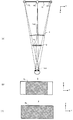
- FIG. 2A shows the positional relationship between the virtual image IV, the intermediate image, and the concave mirror 4 when the observer's head exists at a position where the eye box EB does not need to be moved (also referred to as “reference position”). Show. Actually, there is a windshield between the concave mirror 4 and the eye point, but the effect is not shown because it is considered to be minor.
- 2B is a front view of the screen 3 in which the intermediate image display range Rc in the screen 3 is indicated by a shaded area in the example of FIG. 2A, and FIG. 2) is a front view of the concave mirror 4 in which the area used for displaying the virtual image IV is indicated by a shaded area.
- the position 9C indicates the center of the virtual image IV
- the position 9L indicates the end of the virtual image IV on the Y axis negative direction side
- the position 9R indicates the end of the virtual image IV on the Y axis positive direction side.
- the positive Y-axis direction is also referred to as “right direction”
- the negative Y-axis direction is also referred to as “left direction”.
- an eye box EB is formed on the optical axis “Lax” of the concave mirror 4 in the XY plan view.
- the eye box EB is set to a width equivalent to the width of both eyes of the observer.
- the virtual image display device 100 displays an intermediate image at the center of the screen 3 in the Y-axis direction, as shown in FIGS. 2 (A) and 2 (B).
- the position of the eye box EB in the Y-axis direction varies according to the position of the intermediate image display range Rc in the Y-axis direction.
- the virtual image display device 100 irradiates substantially the entire surface of the concave mirror 4 with the light of the intermediate image of the screen 3.
- the line connecting the left end position 9L of the virtual image IV and the left eye of the observer, and the line connecting the right end position 9R and the right eye of the observer are both in the Y-axis direction of the concave mirror 4. Pass through the end.
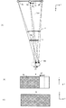
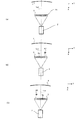
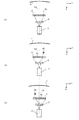
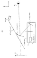
- FIG. 3A shows the positional relationship between the virtual image IV, the intermediate image, and the concave mirror 4 when the observer's head moves to the right from the reference position.
- 3B is a front view of the screen 3 in which the position of the intermediate image display range Rc in the case of FIG. 3A is indicated by a shaded area
- FIG. 3C is an example of FIG. It is the front view of the concave mirror 4 which showed the area
- the observer's head has moved to the right by the width of the arrow A1 from the example of FIG.
- the virtual image display device 100 moves the intermediate image display range Rc to the left side on the opposite side by the width of the arrow A2, as shown in FIG. 3B, in order to align the eye box EB with the moved eye point.
- the virtual image IV displayed based on the light of the intermediate image on the screen 3 has an arrow A3 in the left direction compared to the case where the observer's head is at the reference position. Move by the width of.
- the line connecting the left end position 9L of the virtual image IV and the left eye of the observer, and the line connecting the right end position 9R and the right eye of the observer pass through the end of the concave mirror 4 in the Y-axis direction.
- the virtual image IV is displayed using substantially the entire surface. Therefore, even when the observer's head moves to the right from the reference position, the virtual image display device 100 makes the maximum use of the function of the concave mirror 4 by shifting the intermediate image to the left.
- the virtual image IV can be enlarged and displayed.
- FIG. 4A shows the optical positional relationship of each element of the virtual image display device 100 when the observer's head moves leftward from the state of FIG. 4B is a front view of the screen 3 in which the position of the intermediate image display range Rc in the case of FIG. 4A is indicated by a shaded area
- FIG. 4C is an example of FIG. It is the front view of the concave mirror 4 which showed the area
- the observer's head has moved to the left by the width of the arrow A4 from the example of FIG.
- the virtual image display device 100 moves the intermediate image display range Rc by the width of the arrow A5 in the right direction on the opposite side, as shown in FIG. 4B, in order to align the eye box EB with the moved eye point.
- the virtual image IV displayed based on the light of the intermediate image on the screen 3 has an arrow A6 in the right direction as compared with the case where the observer's head is at the reference position. Move by the width of.
- the line connecting the left end position 9L of the virtual image IV and the left eye of the observer, and the line connecting the right end position 9R and the right eye of the observer all pass through the end of the concave mirror 4 in the Y-axis direction. Therefore, as shown in FIG. 4C, in the example of FIG. 4A, the virtual image IV is displayed using substantially the entire surface of the concave mirror 4. Therefore, even when the observer's head moves to the left from the reference position, the virtual image display device 100 makes the maximum use of the function of the concave mirror 4 by shifting the intermediate image to the right. The virtual image IV can be enlarged and displayed.
- the virtual image display device 100 moves the eye image EB to the right by moving the intermediate image display range Rc to the left, and moves the eye image EB to the right by moving the eye box EB to the right. Move EB to the left.
- the virtual image display apparatus 100 can suitably follow the eye box EB to the eye point after the movement even when the observer's head moves in the Y-axis direction from the reference position.
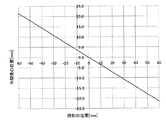
- FIG. 5 is a graph showing the relationship between the position of the observer's head in the Y-axis direction and the position of the intermediate image on the screen 3.
- FIG. 5 the positions of the observer's head and the position of the intermediate image on the screen 3 in FIG.
- the amount of shift of the intermediate image on the screen 3 required when the observer's head moves is approximately proportional to the amount of movement of the observer's head, and the shift direction of the intermediate image Is the direction opposite to the direction of movement of the observer's head. Therefore, the virtual image display apparatus 100 moves the position of the intermediate image on the screen 3 according to the graph of FIG. 5 based on the detected relative position of the observer's head relative to the reference position. Thereby, the eye box EB can be made to follow an eye point, and the virtual image IV can be suitably visually recognized by an observer.
- FIG. 6 is a graph showing the relationship between the size of the concave mirror 4 in the Y-axis direction and the angle of view of the virtual image IV.
- a solid line represents a value of the present invention, and a broken line represents a value of a comparative example described later.
- the size of the concave mirror 4 is limited in design.
- the irradiation area of the concave mirror 4 is set to the substantially entire surface of the concave mirror 4.
- the field angle of the virtual image IV can be suitably widened by making maximum use of the function of the concave mirror 4.
- the size of the concave mirror necessary to obtain a certain angle of view can be made smaller than before.
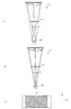
- FIG. 7 shows a comparative example in which the width of the eye box EB in the Y-axis direction is set to about twice the interval between the eyes of the observer.
- FIG. 7A shows light rays that are incident on both end positions of the eye box EB
- FIG. 7B is incident on the eye point when an eye point exists in the center of the eye box EB.
- FIG. 7C is a front view of the concave mirror 4 in which the area used for displaying the virtual image IV in the example of FIG. 7B is indicated by a shaded area.
- the light incident on both end positions of the eye box EB is configured to pass through both ends of the concave mirror 4, and the observer's head is the width of the eye box EB. Even if it is a case where it shifts
- FIGS. 7B and 7C when there is an eye point in the central portion of the eye box EB, both end portions of the concave mirror 4 are not used. Further, even when the eye point is present at an arbitrary position in the eye box EB, an unused area is generated in the concave mirror 4. Thus, in the comparative example, an unused area is generated in the concave mirror 4 because the width of the eye box EB is wider than the width of both eyes of the observer.
- the width of the eye box EB is adjusted to the width of the eye so that the substantially entire surface of the concave mirror 4 is used, and the eye box EB is moved according to the position of the observer's head.
- region of the concave mirror 4 can be expanded rather than the case of a comparative example, and the angle of view of the virtual image IV can be suitably widened.
- the control unit 5 of the virtual image display apparatus 100 sets the substantially entire surface of the screen 3 as the projection range of the projector 2 and sets a part of the projection range as the intermediate image display range Rc.
- the intermediate image display range Rc is moved according to the position of the part.
- FIG. 8 is a diagram showing an outline of the intermediate image position adjustment method according to the first adjustment example.
- FIG. 8A shows the relationship between the projection range of the projector 2 and the position of the intermediate image in the case of FIG. 2A where the eye point is at the reference position
- FIG. FIG. 8A shows the relationship between the projection range of the projector 2 and the position of the intermediate image in the case of FIG. 3A where the eye point is on the right side of the reference position
- FIG. 8C shows the eye point on the left side of the reference position
- FIG. 4A shows the relationship between the projection range of the projector 2 and the position of the intermediate image in the case of FIG.
- the projector 2 is arranged so that substantially the entire surface of the screen 3 is within the projection range. Further, only a part of the projection range of the projector 2 is used for displaying an intermediate image.
- the virtual image display device 100 displays the virtual image IV so that the center position 9C of the virtual image IV overlaps the optical axis Lax, as in FIG. An intermediate image is displayed using only the central portion.
- the virtual image display device 100 moves the virtual image IV to the left by the arrow A3 as in FIG. 3A, so that the intermediate image display range Rc is moved to the arrow within the projection range.
- the virtual image display device 100 moves the virtual image IV to the right by the arrow A6 as in FIG. 4A, so that the intermediate image display range Rc is moved to the arrow within the projection range. Only the width of A5 is moved rightward from the position of FIG.
- the virtual image display device 100 uses the substantially entire surface of the screen 3 as the projection range of the projector 2 and moves the intermediate image display range Rc within the projection range.
- the point can be suitably followed.
- control unit 5 of the virtual image display device 100 has an optical element between the projector 2 and the screen 3 that can change the direction of light from the projector 2 in accordance with the applied voltage.
- the direction of the light emitted from the projector 2 is changed according to the position of the person's head.
- FIG. 9 is a diagram showing an overview of the intermediate image position adjustment method according to the second adjustment example.
- FIG. 9A shows the optical path of the emitted light of the projector 2 in the case of FIG. 2A where the eye point exists at the reference position
- FIG. 9B shows the eye point from the reference position
- FIG. 9C also shows the optical path of the emitted light of the projector 2 in the case of FIG. 3A on the right side
- FIG. 9C shows the projector 2 in the case of FIG. 4A in which the eye point is on the left side of the reference position.
- the optical path of the emitted light is shown.
- a liquid crystal lens 8 is provided between the projector 2 and the screen 3 at a position where the emitted light of the projector 2 is irradiated. ing.
- the voltage applied to the liquid crystal lens 8 is controlled by the control unit 5 (not shown), and the apparent refractive index distribution of the liquid crystal lens 8 changes according to the applied voltage.
- the control unit 5 stores in advance a map or the like of an applied voltage for realizing an appropriate refractive index distribution of the liquid crystal lens 8 for each position in the Y-axis direction of the observer's head, The voltage applied to the liquid crystal lens 8 is determined from the position of the observer's head detected with reference to the map.
- control unit 5 controls the liquid crystal lens 8 so that the refractive index is about 1, and irradiates the screen 3 without changing the direction of the emitted light of the projector 2.
- the intermediate image display range Rc is arranged at the center portion of the screen 3, and the eye box EB overlaps the eye point on the optical axis Lax.
- the control unit 5 moves the intermediate image display range Rc in the left direction by the arrow A2 from the example of FIG.
- the refractive index distribution of the liquid crystal lens 8 is adjusted by applying a predetermined voltage to the liquid crystal lens 8 so that the light from the projector 2 is directed leftward.
- the control unit 5 enters the liquid crystal lens 8 in order to move the intermediate image display range Rc in the screen 3 to the right by the arrow A5 from the example of FIG. 9A.
- a predetermined voltage is applied to the liquid crystal lens 8 so as to adjust the refractive index distribution of the liquid crystal lens 8 so that the light from the projector 2 afterward is directed in the right direction.
- the virtual image display device 100 can also suitably adjust the position of the intermediate image display range Rc by controlling the voltage applied to the liquid crystal lens 8 provided between the projector 2 and the screen 3. .
- control unit 5 moves the intermediate image display range Rc by adjusting the position of the projector 2 according to the position of the observer's head.
- FIG. 10 is a diagram showing an outline of the intermediate image position adjustment method according to the third adjustment example.
- FIG. 10A shows the positional relationship between the projector 2 and the screen 3 in the case of FIG. 2A where the eye point exists at the reference position
- FIG. 10B shows the eye point at the reference position
- 3A shows the positional relationship between the projector 2 and the screen 3 in the case of FIG. 3A on the right side
- FIG. 10C shows the case of FIG. 4A in which the eye point is on the left side of the reference position.
- the positional relationship between the projector 2 and the screen 3 is shown.
- the projector 2 displays an intermediate image over the entire projection range, and is movable in the Y-axis direction based on the control of the control unit 5.
- the control unit 5 moves the projector 2 by the same movement direction and movement amount as the necessary movement direction and movement amount of the intermediate image according to the detected position of the head of the observer.
- the control unit 5 arranges the projector 2 so that the projector 2 is positioned on the optical axis Lax in order to arrange the intermediate image display range Rc at the center of the screen 3.
- the intermediate image display range Rc is moved from the center of the screen 3 to the left by the width of the arrow A2 from the state of FIG.
- the projector 2 is moved by the same distance (that is, the width of the arrow A2 in the left direction).
- the intermediate image display range Rc is moved from the center of the screen 3 to the right by the width of the arrow A5 from the state of FIG.
- the projector 2 is moved by the same distance (that is, the width of the arrow A5 in the right direction).
- the virtual image display device 100 can suitably adjust the position of the intermediate image display range Rc also by adjusting the position of the projector 2 in the Y-axis direction.
- the projector 2 is configured to be movable in the Y-axis direction and to be adjustable in direction.
- the control unit 5 adjusts the position and orientation of the projector 2 according to the position of the observer's head, and moves the intermediate image display range Rc so that the eye point is included in the eye box EB.
- the virtual image IV is visually recognized with high luminance.
- the position and orientation of the projector 2 according to the position of the observer's head will be described in detail with reference to FIGS. 11 to 13.
- FIG. 11A shows an optical path of light corresponding to the intermediate image when the observer's head is present at the reference position.
- Light rays LL, LC, and LR respectively indicate principal rays (that is, light rays having the brightest brightness) after passing through the left end position 10L, the center position 10C, and the right end position 10R of the intermediate image.
- FIG. 11B illustrates diffused light at the positions 10L, 10C, and 10R in addition to the light beams LL, LC, and LR.
- the incident light of the screen 3 is diffused by a predetermined diffusion angle “ ⁇ ” with the principal ray as the center.
- the projector 2 is disposed on the optical axis of the concave mirror 4 and is directed toward the center of the screen 3.
- the observer can view the virtual image IV regardless of the diffusion angle ⁇ of the screen 3. It is possible to see clearly.
- FIG. 12A shows the arrangement of the projector 2 and the light beam emitted by the projector 2 when the observer's head moves from the reference position to the right by the width indicated by the arrow A1.
- FIG. 12B is an enlarged view of part of FIG.
- the control unit 5 moves the projector 2 in the opposite left direction.
- the projector 2 is moved by the width, and the projector 2 is tilted by a predetermined angle so as to face the screen 3.
- the intermediate image moves to the left by a width necessary for moving the virtual image IV to the left by the width of the arrow A3 (specifically, the width of the arrow A2 in FIG. 3B).
- the principal rays LR, LC, and LL emitted from the positions 10R, 10C, and 10L of the intermediate image are reflected by the concave mirror 4 and reach the vicinity of the center of the eye box EB.
- the movement amount of the projector 2 is larger than the movement amount of the intermediate image from the position of FIG. 11 (A) (see the arrow A2 in FIG. 10B). Bigger than A7. Therefore, in this example, the projector 2 is tilted so that light for displaying an intermediate image is irradiated at the positions 10R, 10C, and 10L.
- FIG. 13A shows the arrangement of the projector 2 and the light beam emitted by the projector 2 when the observer's head moves leftward from the reference position by the width indicated by the arrow A4.
- FIG. 13B is an enlarged view of part of FIG.
- the control unit 5 moves the projector 2 to the right in the opposite direction.
- the projector 2 is moved by a predetermined width and tilted by a predetermined angle so that the projector 2 faces the screen 3.
- the intermediate image moves to the right by a width necessary for moving the virtual image IV to the right by the width of the arrow A6 (specifically, the width of the arrow A5 in FIG. 4B).
- the principal rays LR, LC, LL from the positions 10R, 10C, 10L of the intermediate image are reflected by the concave mirror 4 and reach the vicinity of the center in the eye box EB.
- the amount of movement of the projector 2 is greater than the amount of movement of the intermediate image from the position of FIG. 11A (see arrow A5 in FIG. 4B). Bigger than A8. Therefore, in this example, the projector 2 is tilted so that light for displaying an intermediate image is irradiated at the positions 10R, 10C, and 10L.
- the virtual image display device 100 is configured according to the detected position of the head of the observer so that the principal ray after passing through the screen 3 is incident near the center of the eye box EB.
- the position and orientation of the projector 2 are adjusted.
- the control unit 5 stores in advance a map or the like indicating an appropriate position and orientation of the projector 2 corresponding to each eye point, and the position of the observer's head detected with reference to the map. From the above, the position and orientation of the projector 2 are determined. Thereby, even if it is a case where the spreading
- Modification 1 The configuration of the virtual image display device 100 illustrated in FIG. 1 is an example, and the configuration of the virtual image display device 100 to which the present invention is applicable is not limited to this.
- FIG. 14 shows another configuration example of the virtual image display device 100.
- a combiner 12 is provided closer to the observer than the windshield 6, and a rising mirror 11 is provided in the light source unit 1 instead of the concave mirror 4.
- the combiner 13 is a half mirror that reflects the light incident from the screen 3 and displays an enlarged image IV corresponding to the incident light.
- the combiner 12 is configured such that a surface on which light from the screen 3 is incident (that is, an incident surface) has a concave shape.
- the combiner 12 corresponds to an example of the “optical element” in the present invention.
- the intermediate image light imaged on the screen 3 is reflected by the rising mirror 11 toward the combiner 12, and the combiner 12 further reflects a part of the incident light to the eye point. Then, the observer visually recognizes the virtual image IV.
- the virtual image display device 100 is configured to irradiate substantially the entire surface of the combiner 12 with the light of the intermediate image formed on the screen 3 and detected based on the first to fourth adjustment examples.
- the position of the virtual image IV is adjusted by moving the position of the intermediate image in the screen 3 according to the position of the head of the observer.
- the virtual image display apparatus 100 can make an observer visually recognize the virtual image IV suitably, making the eye box EB follow an eye point like an Example.
- the virtual image display device 100 may have a liquid crystal display as a light source.
- FIG. 15 shows a configuration example of the virtual image display device 100 according to this modification.
- the virtual image display device 100 includes a liquid crystal display 13 instead of the projector 2 and the screen 3.
- the light of the image displayed on the liquid crystal display 13 is applied to substantially the entire surface of the concave mirror 4.
- the liquid crystal display 13 changes the display position of the image displayed as the virtual image IV based on the first adjustment example, the third adjustment example, or the fourth adjustment example based on the control of the control unit 5.
- the liquid crystal display 13 uses only a part of the displayable area as an image display area, and displays the above-described image display according to the detected position of the head of the observer detected by the control unit 5. Move the area within the displayable area.
- the liquid crystal display 13 is movable and changes its position or / and orientation based on the control of the control unit 5 according to the position of the head of the observer.
- the liquid crystal display 13 and the control unit 5 may be configured integrally.
- the virtual image display device 100 can move the eye box EB in accordance with the eye point, and can make the virtual image IV suitably visible to the observer, as in the embodiment.
- the liquid crystal display 13 is an example of a “light source unit”
- the panel of the liquid crystal display 13 is an example of a “first display unit”.
- the screen 3 is designed to have a width larger than the intermediate image display range Rc in the Y-axis direction so that light for displaying the intermediate image is irradiated even if the display position of the intermediate image is moved. It was.
- the screen 3 may have a width equivalent to the intermediate image display range Rc in the Y-axis direction, and the position in the Y-axis direction may be adjustable according to the position of the intermediate image to be displayed.
- the screen 3 is movable in the Y-axis direction based on the control of the control unit 5, and the control unit 5 adjusts the position of the screen 3 in the Y-axis direction according to the position of the intermediate image to be displayed. Then, the entire light constituting the intermediate image is irradiated onto the screen 3.
Landscapes
- Engineering & Computer Science (AREA)
- Physics & Mathematics (AREA)
- General Physics & Mathematics (AREA)
- Theoretical Computer Science (AREA)
- Chemical & Material Sciences (AREA)
- Combustion & Propulsion (AREA)
- Transportation (AREA)
- Mechanical Engineering (AREA)
- Computer Hardware Design (AREA)
- Optics & Photonics (AREA)
- Instrument Panels (AREA)
Abstract
虚像表示装置100は、プロジェクタ2と、スクリーン3と、凹面鏡4と、制御部5とを備える。制御部5は、観察者の眼の位置に関する位置情報を取得する。プロジェクタ2は、制御部5の制御に基づき、スクリーン3に中間像を表示させることで、ウィンドシールド6を介して観察者に虚像IVを視認させるための光を、観察者の目の位置によらずに凹面鏡4における同一範囲に照射する。制御部5は、観察者の目の位置に関する位置情報に基づいて、スクリーン3に表示させる中間像の表示位置を変更させる。
Description
本発明は、虚像として画像を視認させる表示装置に関する。
従来から、ユーザの目の位置(アイポイント)から虚像として画像を視認させるヘッドアップディスプレイなどの表示装置が知られている。例えば、特許文献1には、表示器が発する光を光学部材で反射させることで観察者に虚像を視認させるヘッドアップディスプレイにおいて、表示器のディスプレイ内での画像の表示位置を変化させることで、虚像を視認可能な位置を変化させる技術が開示されている。
一般に、ヘッドアップディスプレイでは、虚像の画角を広げるためにレンズ機能を有する光学素子が用いられる。ここで、虚像の画角を大きくするには、上述の光学素子を大きくする必要があるが、製品設計上、光学素子のサイズには制限があるため、光学素子のサイズをあまり大きくすることはできない。よって、虚像の画角を広げるためには、光学素子の大型化以外の工夫が必要となる。これについて、特許文献1には、何ら開示及び示唆がない。
本発明が解決しようとする課題は上記のようなものが例として挙げられる。本発明は、虚像の視認性を好適に向上させることが可能な表示装置を提供することを主な目的とする。
請求項に記載の発明は、表示装置であって、凹面形状の反射面を有する光学素子と、観察者の眼の位置に関する位置情報を取得する取得部と、第1表示部に画像を表示させることで、第2表示部を介して前記観察者に虚像を視認させるための光を、前記観察者の目の位置によらずに前記光学素子おける同一範囲に照射する光源部と、前記位置情報に基づいて、前記第1表示部に表示させる前記画像の表示位置を変更させる表示位置制御部と、を備えることを特徴とする。
また、請求項に記載の発明は、凹面形状の反射面を有する光学素子と、第1表示部に画像を表示させることで、第2表示部を介して前記観察者に虚像を視認させるための光を、前記観察者の目の位置によらずに前記光学素子おける同一範囲に照射する光源部と、を有する表示装置が実行する制御方法であって、観察者の眼の位置に関する位置情報を取得する取得工程と、前記位置情報に基づいて、前記第1表示部に表示させる前記画像の表示位置を変更させる表示位置制御工程と、を有することを特徴とする。
また、請求項に記載の発明は、凹面形状の反射面を有する光学素子と、第1表示部に画像を表示させることで、第2表示部を介して前記観察者に虚像を視認させるための光を、前記観察者の目の位置によらずに前記光学素子おける同一範囲に照射する光源部と、を有する表示装置を制御するコンピュータが実行するプログラムであって、観察者の眼の位置に関する位置情報を取得する取得手段と、前記位置情報に基づいて、前記第1表示部に表示させる前記画像の表示位置を変更させる表示位置制御手段として前記コンピュータを機能させることを特徴とする。
本発明の1つの好適な実施形態では、表示装置は、凹面形状の反射面を有する光学素子と、観察者の眼の位置に関する位置情報を取得する取得部と、第1表示部に画像を表示させることで、第2表示部を介して前記観察者に虚像を視認させるための光を、前記観察者の目の位置によらずに前記光学素子おける同一範囲に照射する光源部と、前記位置情報に基づいて、前記第1表示部に表示させる前記画像の表示位置を変更させる表示位置制御部と、を備える。
上記表示装置は、光学素子と、取得部と、光源部と、表示位置制御部とを備える。光学素子は、凹面形状の反射面を有する。取得部は、観察者の眼の位置に関する位置情報を取得する。光源部は、第1表示部に画像を表示させることで、第2表示部を介して観察者に虚像を視認させるための光を、観察者の目の位置によらずに光学素子おける同一範囲に照射する。表示位置制御部は、観察者の目の位置に関する位置情報に基づいて、第1表示部に表示させる画像の表示位置を変更させる。この態様では、表示装置は、観察者が虚像を視認できるように、画像の表示位置を調整することで、虚像の位置を移動させる。このとき、表示装置は、観察者に虚像を視認させるための光を、観察者の目の位置によらずに光学素子おける同一範囲に照射する。これにより、表示装置は、観察者の頭部の位置が変化した場合であっても、光学素子による虚像の拡大機能を好適に利用し、観察者に広い画角の虚像を好適に視認させることができる。
上記表示装置の一態様では、前記光源部は、前記表示位置制御部の制御に基づき移動自在であり、前記表示位置制御部は、前記光源部を移動させることで、前記画像の表示位置を変更させる。これにより、表示装置は、観察者が虚像を視認できるように虚像の位置を好適に移動させることができる。
上記表示装置の他の一態様では、前記第2表示部は、中間像を生成するスクリーンであり、前記表示位置制御部は、前記スクリーンで拡散した光の主光線が前記目の位置に到達するように、前記光源部の位置及び向きを調整する。この態様では、表示装置は、スクリーンの拡散角度によらず、虚像を観察者に好適な明るさにより視認させることができる。
上記表示装置の他の一態様では、表示装置は、前記第1表示部と前記光源部との間に設けられ、印加される電圧に基づき屈折率分布が変化するレンズをさらに備え、前記表示位置制御部は、前記レンズに印加する電圧を調整することで、前記第1表示部に表示させる前記画像の表示位置を変更させる。この態様によっても、表示装置は、画像の表示位置を移動させて、観察者が虚像を視認できるように虚像の位置を好適に移動させることができる。
上記表示装置の他の一態様では、前記第2表示部は、前記画像の表示範囲よりも大きく設計され、前記表示位置制御部は、前記位置情報に基づいて、前記第1表示部における前記画像の表示位置を変更させる。この態様により、表示装置は、第1表示部に表示させる画像の表示位置を好適に移動させることができる。
上記表示装置の他の一態様では、前記第2表示部は、前記表示位置制御部の制御に基づき移動自在であり、前記表示位置制御部は、前記画像を表示すべき位置に応じて前記第1表示部を移動させる。この態様により、第1表示部の小型化を実現しつつ、画像を適切な位置に表示させることができる。
上記表示装置の他の一態様では、前記光源部は、前記第1表示部を液晶パネルとする液晶ディスプレイである。この態様によっても、表示装置は、虚像を好適に観察者に視認させることができる。
上記表示装置の他の一態様では、前記第2表示部は、車両のウィンドシールドであり、前記光学素子は、前記第1表示部の光を前記ウィンドシールドに向けて反射する。この態様では、表示装置は、光学素子により拡大させた虚像を、ウィンドシールドを介して車両の搭乗者に好適に視認させることができる。
上記表示装置の他の一態様では、前記光学素子及び前記第2表示部は、車両のウィンドシールドと観察者との間に設けられた曲面形状のコンバイナである。この態様によっても、表示装置は、コンバイナへの照射領域を調整することで、虚像の画角を好適に広くし、車両の搭乗者に視認させることができる。
上記表示装置の他の一態様では、前記虚像を視認可能な幅は、前記観察者の両目の幅と略同一に設定される。これにより、表示装置は、光学素子への第1表示部の画像の光の照射領域を、最大限に大きくすることができる。
本発明の他の好適な実施形態では、凹面形状の反射面を有する光学素子と、第1表示部に画像を表示させることで、第2表示部を介して前記観察者に虚像を視認させるための光を、前記観察者の目の位置によらずに前記光学素子おける同一範囲に照射する光源部と、を有する表示装置が実行する制御方法であって、観察者の眼の位置に関する位置情報を取得する取得工程と、前記位置情報に基づいて、前記第1表示部に表示させる前記画像の表示位置を変更させる表示位置制御工程と、を有する。表示装置は、この制御方法を実行することで、観察者の頭部の位置が変化した場合であっても、観察者に広い画角の虚像を好適に視認させることができる。
本発明の他の好適な実施形態では、凹面形状の反射面を有する光学素子と、第1表示部に画像を表示させることで、第2表示部を介して前記観察者に虚像を視認させるための光を、前記観察者の目の位置によらずに前記光学素子おける同一範囲に照射する光源部と、を有する表示装置を制御するコンピュータが実行するプログラムであって、観察者の眼の位置に関する位置情報を取得する取得手段と、前記位置情報に基づいて、前記第1表示部に表示させる前記画像の表示位置を変更させる表示位置制御手段として前記コンピュータを機能させる。コンピュータは、このプログラムを実行することで、観察者の頭部の位置が変化した場合であっても、観察者に広い画角の虚像を好適に視認させることができる。
以下、図面を参照して本発明の好適な実施例について説明する。
[概略構成]
図1は、実施例に係る虚像表示装置100の概略構成図である。図1に示すように、虚像表示装置100は、ウィンドシールド6を有する車両に搭載され、画像をユーザの目の位置(「アイポイント」とも呼ぶ。)から虚像「IV」として視認させるヘッドアップディスプレイである。虚像表示装置100は、光源ユニット1と、カメラ7とを有する。以後では、地面に垂直な方向をZ軸、車両の進行方向をX軸、Z軸及びX軸に垂直な車両の側面方向をY軸とし、各軸の正方向を図1及び後述する図2が示す方向に定める。
図1は、実施例に係る虚像表示装置100の概略構成図である。図1に示すように、虚像表示装置100は、ウィンドシールド6を有する車両に搭載され、画像をユーザの目の位置(「アイポイント」とも呼ぶ。)から虚像「IV」として視認させるヘッドアップディスプレイである。虚像表示装置100は、光源ユニット1と、カメラ7とを有する。以後では、地面に垂直な方向をZ軸、車両の進行方向をX軸、Z軸及びX軸に垂直な車両の側面方向をY軸とし、各軸の正方向を図1及び後述する図2が示す方向に定める。
光源ユニット1は、レーザ光を出射するプロジェクタ2と、スクリーン3と、凹面鏡4と、制御部5とを有する。
プロジェクタ2は、赤色、緑色、青色のレーザ光源、及び、レーザ光源から出射されたレーザ光を走査するスキャン機構(走査機構)などを有する。プロジェクタ2から照射された光は、スクリーン3に入射する。後述するように、プロジェクタ2は、好適には、制御部5から送信される制御信号に基づき移動自在に構成される。プロジェクタ2は、本発明における「光源部」の一例である。
スクリーン3は、プロジェクタ2から光が照射されることで、ユーザに提示する画像の中間像を形成する。例えば、スクリーン3は、射出瞳拡大素子(EPE)であって、複数のマイクロレンズが配列されたマイクロレンズアレイである。スクリーン3から出射された光は、凹面鏡4に入射する。スクリーン3は、好適には、プロジェクタ2による投影範囲よりも大きくなるように設計される。スクリーン3は、本発明における「第1表示部」の一例である。
凹面鏡4は、スクリーン3から出射された光を反射し、ウィンドシールド6へ到達させる。この場合、凹面鏡4は、光を反射することで、当該光が示す画像を拡大させる。凹面鏡4で反射された光は、さらにウィンドシールド6で反射され、運転者のアイポイントへ到達する。これにより、運転者は、虚像IVを視認する。後述するように、本実施例では、スクリーン3の中間像の光は、凹面鏡4の略全面に照射される。この場合、虚像IVが視認可能なアイポイントの範囲(「アイボックスEB」とも呼ぶ。)のY軸方向の幅は、観察者の目の幅と同等の幅に設定される。なお、凹面鏡4は、本発明における「光学素子」の一例であり、ウィンドシールド6は、本発明における「第2表示部」の一例である。
カメラ7は、虚像IVの観察者である運転者の顔を撮影可能な向きに設置され、撮影した画像(「撮影画像Im」とも呼ぶ。)を光源ユニット1の制御部5へ供給する。
制御部5は、CPU(Central Processing Unit)、ROM(Read Only Memory)及びRAM(Random Access Memory)などを含んでおり、光源ユニット1全体の制御を行う。実施例では、制御部5は、カメラ7から撮影画像Imを受信し、公知の画像認識技術により、撮影画像Imに基づき虚像IVの観察者である運転者の頭の位置を検出する。そして、制御部5は、検出した頭の位置に合わせて、アイボックスEBを移動させることで、運転者に虚像IVを視認させる。この場合、制御部5は、頭の位置に応じて、虚像IVに対応する中間像のスクリーン3での表示位置(「中間像表示範囲Rc」とも呼ぶ。)、即ち、中間像を生成するための光のスクリーン3への照射範囲を変更し、虚像IVの表示位置を調整することで、アイボックスEBを移動させる。制御部5は、本発明における「取得手段」、「表示位置制御手段」、及び本発明におけるプログラムを実行するコンピュータの一例である。なお、プロジェクタ2と制御部5とは、一体に構成されていてもよい。
[アイポイントに応じた中間像表示範囲]
次に、検出した運転者の頭部に応じた位置(即ちアイポイント)にアイボックスEBを移動させるための中間像の表示位置の制御について説明する。概略的には、虚像表示装置100は、検出したアイポイントに基づき、アイボックスEBをY軸正方向に移動させる場合には、中間像表示範囲Rcを反対方向であるY軸負方向に移動させ、アイボックスEBをY軸負方向に移動させる場合には、中間像表示範囲RcをY軸正方向に移動させる。
次に、検出した運転者の頭部に応じた位置(即ちアイポイント)にアイボックスEBを移動させるための中間像の表示位置の制御について説明する。概略的には、虚像表示装置100は、検出したアイポイントに基づき、アイボックスEBをY軸正方向に移動させる場合には、中間像表示範囲Rcを反対方向であるY軸負方向に移動させ、アイボックスEBをY軸負方向に移動させる場合には、中間像表示範囲RcをY軸正方向に移動させる。
図2(A)は、アイボックスEBを移動させる必要がない位置(「基準位置」とも呼ぶ。)に観察者の頭部が存在する場合の虚像IV、中間像、及び凹面鏡4の位置関係を示す。実際には凹面鏡4とアイポイントの間にウィンドシールドがあるが、その影響は軽微なものとみなされるため図示していない。図2(B)は、図2(A)の例において、スクリーン3内の中間像表示範囲Rcを網掛領域により示したスクリーン3の正面図であり、図2(C)は、図2(A)の例において、虚像IVの表示に使用された領域を網掛領域により示した凹面鏡4の正面図である。以後において、位置9Cは、虚像IVの中心部を示し、位置9Lは、虚像IVのY軸負方向側の端部を示し、位置9Rは、虚像IVのY軸正方向側の端部を示す。なお、以後では、Y軸正方向を「右方向」、Y軸負方向を「左方向」とも表記する。
図2(A)に示すように、観察者の頭部が基準位置に存在する場合、XY平面視において、凹面鏡4の光軸「Lax」上にアイボックスEBが形成される。ここで、アイボックスEBは、観察者の両目の幅と同等の幅に設定されている。この場合、虚像表示装置100は、図2(A)及び図2(B)に示すように、Y軸方向におけるスクリーン3の中央に中間像を表示している。後述するように、Y軸方向におけるアイボックスEBの位置は、Y軸方向での中間像表示範囲Rcの位置に応じて変動する。
また、図2(C)に示すように、虚像表示装置100は、スクリーン3の中間像の光を、凹面鏡4の略全面に照射させている。この場合、図2(A)に示すように、虚像IVの左端位置9Lと観察者の左目を結ぶ線、右端位置9Rと観察者の右目を結ぶ線は、いずれも凹面鏡4のY軸方向の端部を通過する。このように、スクリーン3の中間像の光を凹面鏡4の略全面に照射させることで、虚像表示装置100は、凹面鏡4の機能を最大限利用して虚像IVの画角を広げることができる。
図3(A)は、観察者の頭部が基準位置から右方向に移動した場合の虚像IV、中間像、及び凹面鏡4の位置関係を示す。図3(B)は、図3(A)の場合における中間像表示範囲Rcの位置を網掛領域により示したスクリーン3の正面図であり、図3(C)は、図3(A)の例で虚像IVの表示に使用された領域を網掛領域により示した凹面鏡4の正面図である。
図3の例では、観察者の頭部は、図2の例から右方向に矢印A1の幅だけ移動している。この場合、虚像表示装置100は、移動後のアイポイントにアイボックスEBを合わせるため、図3(B)に示すように、中間像表示範囲Rcを反対側の左方向に矢印A2の幅だけ移動させる。この場合、図3(A)に示すように、スクリーン3の中間像の光に基づき表示される虚像IVは、観察者の頭部が基準位置にある場合と比較して、左方向に矢印A3の幅だけ移動する。そして、この場合、虚像IVの左端位置9Lと観察者の左目、右端位置9Rと観察者の右目とを結ぶ線は、いずれも凹面鏡4のY軸方向の端部を通過するため、凹面鏡4の略全面を使用して虚像IVが表示される。従って、観察者の頭部が基準位置から右方向に移動した場合であっても、虚像表示装置100は、中間像を左方向に遷移させることで、凹面鏡4の機能を最大限利用して、虚像IVを拡大して表示させることができる。
図4(A)は、図2(A)の状態から観察者の頭部が左方向に移動した場合の虚像表示装置100の各要素の光学的な位置関係を示す。図4(B)は、図4(A)の場合における中間像表示範囲Rcの位置を網掛領域により示したスクリーン3の正面図であり、図4(C)は、図4(A)の例で虚像IVの表示に使用された領域を網掛領域により示した凹面鏡4の正面図である。
図4の例では、観察者の頭部は、図2の例から左方向に矢印A4の幅だけ移動している。この場合、虚像表示装置100は、移動後のアイポイントにアイボックスEBを合わせるため、図4(B)に示すように、中間像表示範囲Rcを反対側の右方向に矢印A5の幅だけ移動させる。この場合、図4(A)に示すように、スクリーン3の中間像の光に基づき表示される虚像IVは、観察者の頭部が基準位置にある場合と比較して、右方向に矢印A6の幅だけ移動する。従って、この場合、虚像IVの左端位置9Lと観察者の左目、右端位置9Rと観察者の右目とを結ぶ線は、いずれも凹面鏡4のY軸方向の端部を通過する。よって、図4(C)に示すように、図4(A)の例では、凹面鏡4の略全面を使用して虚像IVが表示されている。従って、観察者の頭部が基準位置から左方向に移動した場合であっても、虚像表示装置100は、中間像を右方向に遷移させることで、凹面鏡4の機能を最大限利用して、虚像IVを拡大して表示させることができる。
このように、虚像表示装置100は、中間像表示範囲Rcを左方向に移動させることで、アイボックスEBを右方向に移動させ、中間像表示範囲Rcを右方向に移動させることで、アイボックスEBを左方向に移動させる。これにより、虚像表示装置100は、観察者の頭部が基準位置からY軸方向に移動した場合であっても、移動後のアイポイントにアイボックスEBを好適に追従させることができる。
図5は、Y軸方向における観察者の頭部の位置と、スクリーン3の中間像の位置との関係を示すグラフである。図5では、図2(A)における観察者の頭部の位置及びスクリーン3における中間像の位置をそれぞれ原点としている。
図5に示すように、観察者の頭部が移動した場合に必要なスクリーン3における中間像のシフト量は、観察者の頭部の移動量におよそ比例し、かつ、当該中間像のシフト方向は、観察者の頭部の移動方向と逆方向となる。よって、虚像表示装置100は、検出した観察者の頭部の基準位置に対する相対位置に基づき、図5のグラフに従い、スクリーン3における中間像の位置を移動させる。これにより、アイボックスEBをアイポイントに追従させて、観察者に虚像IVを好適に視認させることができる。
図6は、Y軸方向における凹面鏡4のサイズと、虚像IVの画角との関係を示すグラフである。実線は本発明の値、破線は後述する比較例の値を表している。図6に示すように、凹面鏡4のサイズが大きいほど、虚像IVの画角は大きくなる。一方、設計上、凹面鏡4の大型化には制約がある。以上を勘案し、実施例では、凹面鏡4の照射領域を凹面鏡4の略全面とする。これにより、凹面鏡4の機能を最大限活用して虚像IVの画角を好適に広くすることができる。つまり、本発明により、ある画角を得るために必要な凹面鏡サイズは従来よりも小さくすることができる。
ここで、観察者の頭部の位置に応じてアイボックスEBを移動させる代わりに、アイボックスEBのY軸方向の幅を大きく設計した比較例について説明する。
図7は、Y軸方向のアイボックスEBの幅を観察者の目の間隔の約2倍に設定した比較例を示す。具体的には、図7(A)は、アイボックスEBの両端位置に入射する光線を示し、図7(B)は、アイボックスEBの中央にアイポイントが存在する場合のアイポイントに入射する光線を示し、図7(C)は、図7(B)の例で虚像IVの表示に使用された領域を網掛領域により示した凹面鏡4の正面図である。
図7(A)に示すように、比較例では、アイボックスEBの両端位置に入射する光が凹面鏡4の両端を通過するように構成されており、観察者の頭部がアイボックスEBの幅の範囲内でY軸方向にずれた場合であっても、観察者は虚像IVを視認することが可能である。一方、図7(B)、(C)に示すように、アイボックスEBの中央部分にアイポイントがある場合、凹面鏡4の両端部分は使用されていない。また、アイポイントがアイボックスルEB内の任意の場所に存在する場合であっても、凹面鏡4には未使用領域が発生する。このように、比較例では、アイボックスEBの幅が観察者の両目の幅よりも広い分、凹面鏡4には未使用領域が発生する。
以上を勘案し、実施例では、凹面鏡4の略全面を使用するようにアイボックスEBの幅を目の幅に合わせ、かつ、観察者の頭部の位置に応じてアイボックスEBを移動させる。これにより、比較例の場合よりも凹面鏡4の使用領域を拡大して虚像IVの画角を好適に広くすることができる。
[中間像の位置調整]
次に、観察者の頭部の位置に応じた中間像の位置調整方法の具体例(第1~第4調整例)について説明する。
次に、観察者の頭部の位置に応じた中間像の位置調整方法の具体例(第1~第4調整例)について説明する。
(第1調整例)
第1調整例では、虚像表示装置100の制御部5は、スクリーン3の略全面をプロジェクタ2の投影範囲とし、当該投影範囲内の一部を中間像表示範囲Rcに設定して観察者の頭部の位置に応じて中間像表示範囲Rcを移動させる。
第1調整例では、虚像表示装置100の制御部5は、スクリーン3の略全面をプロジェクタ2の投影範囲とし、当該投影範囲内の一部を中間像表示範囲Rcに設定して観察者の頭部の位置に応じて中間像表示範囲Rcを移動させる。
図8は、第1調整例に係る中間像の位置調整方法の概要を示す図である。具体的に、図8(A)は、アイポイントが基準位置に存在する図2(A)の場合のプロジェクタ2の投射範囲と中間像の位置との関係を示し、図8(B)は、アイポイントが基準位置よりも右側にある図3(A)の場合のプロジェクタ2の投射範囲と中間像の位置との関係を示し、図8(C)は、アイポイントが基準位置よりも左側にある図4(A)の場合のプロジェクタ2の投射範囲と中間像の位置との関係を示す。
図8(A)~(C)に示すように、第1調整例では、プロジェクタ2は、スクリーン3の略全面が投影範囲となるように配置されている。また、プロジェクタ2の投影範囲のうち、一部のみが中間像の表示に用いられている。そして、図8(A)の例では、虚像表示装置100は、図2(A)と同様に、虚像IVの中央位置9Cが光軸Laxと重なるように虚像IVを表示させるため、投影範囲の中央部分のみを用いて中間像を表示させている。また、図8(B)の例では、虚像表示装置100は、図3(A)と同様に、虚像IVを矢印A3だけ左方向に移動させるため、投影範囲内で中間像表示範囲Rcを矢印A2の幅だけ図8(A)の位置から左方向に移動させている。さらに、図8(C)の例では、虚像表示装置100は、図4(A)と同様に、虚像IVを矢印A6だけ右方向に移動させるため、投影範囲内で中間像表示範囲Rcを矢印A5の幅だけ図8(A)の位置から右方向に移動させている。
このように、第1調整例では、虚像表示装置100は、スクリーン3の略全面をプロジェクタ2の投影範囲とし、当該投影範囲内で中間像表示範囲Rcを移動させることで、アイボックスEBをアイポイントに好適に追従させることができる。
(第2調整例)
第2調整例では、虚像表示装置100の制御部5は、印加する電圧に応じてプロジェクタ2からの光の向きを変更可能な光学素子を、プロジェクタ2とスクリーン3との間に有し、観察者の頭部の位置に応じてプロジェクタ2から出射された光の向きを変える。
第2調整例では、虚像表示装置100の制御部5は、印加する電圧に応じてプロジェクタ2からの光の向きを変更可能な光学素子を、プロジェクタ2とスクリーン3との間に有し、観察者の頭部の位置に応じてプロジェクタ2から出射された光の向きを変える。
図9は、第2調整例に係る中間像の位置調整方法の概要を示す図である。具体的に、図9(A)は、アイポイントが基準位置に存在する図2(A)の場合のプロジェクタ2の出射光の光路を示し、図9(B)は、アイポイントが基準位置よりも右側にある図3(A)の場合のププロジェクタ2の出射光の光路を示し、図9(C)は、アイポイントが基準位置よりも左側にある図4(A)の場合のプロジェクタ2の出射光の光路を示す。
図9(A)~(C)に示すように、第2調整例では、プロジェクタ2とスクリーン3との間であって、プロジェクタ2の出射光が照射される位置に、液晶レンズ8が設けられている。液晶レンズ8は、図示しない制御部5により、印加される電圧が制御され、印加される電圧に応じて、見かけ上の液晶レンズ8の屈折率分布が変化する。そして、例えば、制御部5は、観察者の頭部のY軸方向の各位置に対して適切な液晶レンズ8の屈折率分布を実現するための印加電圧のマップ等を予め記憶しておき、当該マップを参照して検出した観察者の頭部の位置から液晶レンズ8への印加電圧を決定する。
図9(A)の例では、制御部5は、液晶レンズ8の屈折率がおよそ1となるように制御し、プロジェクタ2の出射光の向きを変えることなくスクリーン3に照射させる。この場合、中間像表示範囲Rcは、スクリーン3の中央部分に配置されることになり、光軸Lax上にあるアイポイントにアイボックスEBが重なる。
また、図9(B)の例では、制御部5は、図9(A)の例から矢印A2だけ左方向に中間像表示範囲Rcをスクリーン3内で移動させるため、液晶レンズ8に入射後のプロジェクタ2の光が左方向に向かうように、液晶レンズ8に所定の電圧を印加して液晶レンズ8の屈折率分布を調整する。同様に、図9(C)の例では、制御部5は、図9(A)の例から矢印A5だけ右方向に中間像表示範囲Rcをスクリーン3内で移動させるため、液晶レンズ8に入射後のプロジェクタ2の光が右方向に向かうように、液晶レンズ8に所定の電圧を印加して液晶レンズ8の屈折率分布を調整する。
このように、虚像表示装置100は、プロジェクタ2とスクリーン3との間に設けられた液晶レンズ8の印加電圧を制御することによっても、好適に中間像表示範囲Rcの位置を調整することができる。
(第3調整例)
第3調整例では、制御部5は、プロジェクタ2の位置を観察者の頭部の位置に応じて調整することで、中間像表示範囲Rcを移動させる。
第3調整例では、制御部5は、プロジェクタ2の位置を観察者の頭部の位置に応じて調整することで、中間像表示範囲Rcを移動させる。
図10は、第3調整例に係る中間像の位置調整方法の概要を示す図である。具体的に、図10(A)は、アイポイントが基準位置に存在する図2(A)の場合のプロジェクタ2及びスクリーン3の位置関係を示し、図10(B)は、アイポイントが基準位置よりも右側にある図3(A)の場合のププロジェクタ2及びスクリーン3の位置関係を示し、図10(C)は、アイポイントが基準位置よりも左側にある図4(A)の場合のプロジェクタ2及びスクリーン3の位置関係を示す。
図10の例では、プロジェクタ2は、投射範囲の全体により中間像を表示するものであって、かつ、制御部5の制御に基づきY軸方向を移動自在である。この場合、制御部5は、検出した観察者の頭部の位置に応じ、中間像の必要な移動方向及び移動量と同一の移動方向及び移動量だけプロジェクタ2を移動させる。
図10(A)の例では、制御部5は、スクリーン3の中心に中間像表示範囲Rcを配置するため、光軸Lax上にプロジェクタ2が位置するように、プロジェクタ2を配置する。また、図10(B)の例では、図10(A)の状態から中間像表示範囲Rcをスクリーン3の中心から左方向に矢印A2の幅だけ移動させるため、制御部5は、同方向に同距離(即ち、左方向に矢印A2の幅)だけプロジェクタ2を移動させる。同様に、図10(C)の例では、図10(A)の状態から中間像表示範囲Rcをスクリーン3の中心から右方向に矢印A5の幅だけ移動させるため、制御部5は、同方向に同距離(即ち、右方向に矢印A5の幅)だけプロジェクタ2を移動させる。
このように、虚像表示装置100は、プロジェクタ2のY軸方向の位置を調整することによっても、好適に中間像表示範囲Rcの位置を調整することができる。
(第4調整例)
第4調整例では、プロジェクタ2は、Y軸方向を移動自在であり、かつ、向きを調整自在に構成される。そして、制御部5は、プロジェクタ2の位置及び向きを観察者の頭部の位置に応じて調整することで、アイポイントがアイボックスEB内に含まれるように中間像表示範囲Rcを移動させつつ、虚像IVを高輝度により視認させる。以後では、図11~図13を参照し、観察者の頭部の位置に応じたプロジェクタ2の位置及び向きについて具体的に説明する。
第4調整例では、プロジェクタ2は、Y軸方向を移動自在であり、かつ、向きを調整自在に構成される。そして、制御部5は、プロジェクタ2の位置及び向きを観察者の頭部の位置に応じて調整することで、アイポイントがアイボックスEB内に含まれるように中間像表示範囲Rcを移動させつつ、虚像IVを高輝度により視認させる。以後では、図11~図13を参照し、観察者の頭部の位置に応じたプロジェクタ2の位置及び向きについて具体的に説明する。
図11(A)は、観察者の頭部が基準位置に存在する場合の中間像に対応する光の光路を示す。なお、光線LL、LC、LRは、それぞれ、中間像の左端位置10L、中央位置10C、及び右端位置10Rを通過後の主光線(即ち輝度が最も明るい光線)を示す。また、図11(B)は、光線LL、LC、LRに加え、各位置10L、10C、10Rでの拡散光を図示したものである。
図11(B)に示すように、スクリーン3の入射光は、主光線を中心として所定の拡散角度「θ」により拡散する。そして、図11(A)の例では、プロジェクタ2は、凹面鏡4の光軸上に配置され、かつ、スクリーン3の中心に向けられている。この場合、スクリーン3を通過後の中間像の主光線は、凹面鏡4を反射してアイボックスEBの中心付近に入射するため、観察者は、スクリーン3の拡散角度θによらず、虚像IVを鮮明に視認することが可能である。
図12(A)は、観察者の頭部が基準位置から矢印A1が示す幅だけ右方向に移動した場合のプロジェクタ2の配置及びプロジェクタ2が出射する光線を示す。図12(B)は、図12(A)の一部を拡大した図である。
図12(A)、(B)に示すように、観察者の頭部が基準位置から矢印A1が示す幅だけ右方向に移動した場合、制御部5は、プロジェクタ2を反対の左方向に所定幅だけ移動させ、かつ、プロジェクタ2をスクリーン3に向けるように所定角度だけ傾ける。この場合、中間像は、虚像IVを左方向に矢印A3の幅分移動させるのに必要な幅(具体的には図3(B)の矢印A2の幅)だけ左方向に移動する。さらに、この場合、中間像の各位置10R、10C、10Lから出射する主光線LR、LC、LLは、それぞれ、凹面鏡4で反射してアイボックスEBの中心付近に到達する。なお、この場合、図12(B)に示すように、図11(A)の位置からの中間像の移動量(図10(B)の矢印A2参照)よりも、プロジェクタ2の移動量が矢印A7の分だけ大きい。よって、この例では、プロジェクタ2は、位置10R、10C、10Lに中間像を表示するための光が照射されるように傾けられている。
図13(A)は、観察者の頭部が基準位置から矢印A4が示す幅だけ左方向に移動した場合のプロジェクタ2の配置及びプロジェクタ2が出射する光線を示す。図13(B)は、図13(A)の一部を拡大した図である。
図13(A)、(B)に示すように、観察者の頭部が基準位置から矢印A4が示す幅だけ左方向に移動した場合、制御部5は、プロジェクタ2を反対方向の右方向に所定幅だけ移動させ、かつ、プロジェクタ2をスクリーン3に向けるように所定角度だけ傾ける。この場合、中間像は、虚像IVを右方向に矢印A6の幅分移動させるのに必要な幅(具体的には図4(B)の矢印A5の幅)だけ右方向に移動する。さらに、この場合、中間像の各位置10R、10C、10Lからの主光線LR、LC、LLは、それぞれ、凹面鏡4で反射してアイボックスEB内の中心付近に到達する。なお、この場合、図13(B)に示すように、図11(A)の位置からの中間像の移動量(図4(B)の矢印A5参照)よりも、プロジェクタ2の移動量が矢印A8の分だけ大きい。よって、この例では、プロジェクタ2は、位置10R、10C、10Lに中間像を表示するための光が照射されるように傾けられている。
このように、第4調整例では、虚像表示装置100は、スクリーン3を通過後の主光線がアイボックスEBの中心付近に入射するように、検出した観察者の頭部の位置に応じて、プロジェクタ2の位置及び向きを調整する。この場合、例えば、制御部5は、各アイポイントに対応する適切なプロジェクタ2の位置及び向きを示すマップ等を予め記憶しておき、当該マップを参照して検出した観察者の頭部の位置からプロジェクタ2の位置及び向きを決定する。これにより、スクリーン3の拡散角度θが小さい場合であっても、好適に観察者に虚像IVを視認させることができる。
[変形例]
次に、上記した実施例の変形例について説明する。なお、以下で提示する変形例は、上記した実施例に適宜組み合わせて実施することができる。
次に、上記した実施例の変形例について説明する。なお、以下で提示する変形例は、上記した実施例に適宜組み合わせて実施することができる。
(変形例1)
図1に示す虚像表示装置100の構成は一例であり、本発明が適用可能な虚像表示装置100の構成は、これに限定されない。
図1に示す虚像表示装置100の構成は一例であり、本発明が適用可能な虚像表示装置100の構成は、これに限定されない。
図14は、虚像表示装置100の他の構成例を示す。図14の例では、ウィンドシールド6よりも観察者側にコンバイナ12が設けられており、さらに、凹面鏡4に代えて、立上げミラー11が光源ユニット1内に設けられている。コンバイナ13は、スクリーン3から入射した光を反射することで、入射光に対応する像を拡大した虚像IVとして表示させるハーフミラーである。具体的には、コンバイナ12は、スクリーン3からの光が入射する面(つまり入射面)が凹面形状に構成されている。なお、コンバイナ12は、本発明における「光学素子」の一例に相当する。そして、図14の例では、スクリーン3で結像された中間像の光は、立上げミラー11でコンバイナ12に向けて反射され、さらにコンバイナ12が入射光の一部をアイポイントに反射することで、観察者に虚像IVを視認させる。
図14の例であっても、虚像表示装置100は、コンバイナ12の略全面にスクリーン3で結像される中間像の光を照射させる構成とし、第1~第4調整例に基づき、検知した観察者の頭部の位置に応じてスクリーン3内での中間像の位置を移動させて虚像IVの位置を調整する。これにより、虚像表示装置100は、実施例と同様、アイポイントにアイボックスEBを追従させ、虚像IVを好適に観察者に視認させることができる。
(変形例2)
虚像表示装置100は、光源として液晶ディスプレイを有してもよい。
虚像表示装置100は、光源として液晶ディスプレイを有してもよい。
図15は、本変形例に係る虚像表示装置100の構成例を示す。図15では、虚像表示装置100は、プロジェクタ2及びスクリーン3に代えて、液晶ディスプレイ13を有する。液晶ディスプレイ13が表示する画像の光は、凹面鏡4の略全面に照射される。
そして、液晶ディスプレイ13は、制御部5の制御に基づき、上述した第1調整例、第3調整例、または、第4調整例に基づき、虚像IVとして表示する画像の表示位置を変更する。例えば、第1調整例によれば、液晶ディスプレイ13は、表示可能領域の一部のみを画像表示領域とし、制御部5が検出した検出した観察者の頭部の位置に応じて上述の画像表示領域を表示可能領域内で移動させる。また、第3、第4調整例によれば、液晶ディスプレイ13は、移動自在であって、観察者の頭部の位置に応じて、制御部5の制御に基づき、位置又は/及び向きを変える。なお、図15の構成例に代えて、液晶ディスプレイ13と制御部5とが一体に構成されてもよい。
これにより、虚像表示装置100は、実施例と同様、アイポイントに応じてアイボックスEBを移動させ、虚像IVを好適に観察者に視認させることができる。なお、本変形例において、液晶ディスプレイ13は、「光源部」の一例であり、液晶ディスプレイ13のパネルは、「第1表示部」の一例である。
(変形例3)
実施例では、スクリーン3は、中間像の表示位置を移動させても中間像を表示するための光が照射されるように、Y軸方向において中間像表示範囲Rcよりも大きい幅に設計されていた。これに代えて、スクリーン3は、Y軸方向において中間像表示範囲Rcと同等の幅を有し、表示させる中間像の位置に応じてY軸方向での位置が調整自在であってもよい。この場合、スクリーン3は、制御部5の制御に基づきY軸方向を移動自在であり、制御部5は、表示させる中間像の位置に応じて、スクリーン3のY軸方向の位置を調整することで、中間像を構成する光の全体をスクリーン3に照射させる。
実施例では、スクリーン3は、中間像の表示位置を移動させても中間像を表示するための光が照射されるように、Y軸方向において中間像表示範囲Rcよりも大きい幅に設計されていた。これに代えて、スクリーン3は、Y軸方向において中間像表示範囲Rcと同等の幅を有し、表示させる中間像の位置に応じてY軸方向での位置が調整自在であってもよい。この場合、スクリーン3は、制御部5の制御に基づきY軸方向を移動自在であり、制御部5は、表示させる中間像の位置に応じて、スクリーン3のY軸方向の位置を調整することで、中間像を構成する光の全体をスクリーン3に照射させる。
1 光源ユニット
2 プロジェクタ
3 スクリーン
4 凹面鏡
5 制御部
6 ウィンドシールド
7 カメラ
11 立上げミラー
12 コンバイナ
13 液晶ディスプレイ
100 虚像表示装置
2 プロジェクタ
3 スクリーン
4 凹面鏡
5 制御部
6 ウィンドシールド
7 カメラ
11 立上げミラー
12 コンバイナ
13 液晶ディスプレイ
100 虚像表示装置
Claims (13)
- 凹面形状の反射面を有する光学素子と、
観察者の眼の位置に関する位置情報を取得する取得部と、
第1表示部に画像を表示させることで、第2表示部を介して前記観察者に虚像を視認させるための光を、前記観察者の目の位置によらずに前記光学素子おける同一範囲に照射する光源部と、
前記位置情報に基づいて、前記第1表示部に表示させる前記画像の表示位置を変更させる表示位置制御部と、
を備えることを特徴とする表示装置。 - 前記光源部は、前記表示位置制御部の制御に基づき移動自在であり、
前記表示位置制御部は、前記光源部を移動させることで、前記画像の表示位置を変更させることを特徴とする請求項1に記載の表示装置。 - 前記第2表示部は、中間像を生成するスクリーンであり、
前記表示位置制御部は、前記スクリーンで拡散した光の主光線が前記目の位置に到達するように、前記光源部の位置及び向きを調整することを特徴とする請求項2に記載の表示装置。 - 前記第1表示部と前記光源部との間に設けられ、印加される電圧に基づき屈折率分布が変化するレンズをさらに備え、
前記表示位置制御部は、前記レンズに印加する電圧を調整することで、前記第1表示部に表示させる前記画像の表示位置を変更させることを特徴とする請求項1に記載の表示装置。 - 前記第2表示部は、前記画像の表示範囲よりも大きく設計され、
前記表示位置制御部は、前記位置情報に基づいて、前記第1表示部における前記画像の表示位置を変更させることを特徴とする請求項1~4のいずれか一項に記載の表示装置。 - 前記第2表示部は、前記表示位置制御部の制御に基づき移動自在であり、
前記表示位置制御部は、前記画像を表示すべき位置に応じて前記第1表示部を移動させることを特徴とする請求項1~4のいずれか一項に記載の表示装置。 - 前記光源部は、前記第1表示部を液晶パネルとする液晶ディスプレイであることを特徴とする請求項1~6のいずれか一項に記載の表示装置。
- 前記第2表示部は、車両のウィンドシールドであり、
前記光学素子は、前記第1表示部の光を前記ウィンドシールドに向けて反射する凹面鏡であることを特徴とする請求項1~7のいずれか一項に記載の表示装置。 - 前記光学素子及び前記第2表示部は、車両のウィンドシールドと観察者との間に設けられた曲面形状のコンバイナであることを特徴とする請求項1~7のいずれか一項に記載の表示装置。
- 前記虚像を視認可能な幅は、前記観察者の両目の幅と略同一に設定されることを特徴とする請求項1~9のいずれか一項に記載の表示装置。
- 凹面形状の反射面を有する光学素子と、第1表示部に画像を表示させることで、第2表示部を介して前記観察者に虚像を視認させるための光を、前記観察者の目の位置によらずに前記光学素子おける同一範囲に照射する光源部と、を有する表示装置が実行する制御方法であって、
観察者の眼の位置に関する位置情報を取得する取得工程と、
前記位置情報に基づいて、前記第1表示部に表示させる前記画像の表示位置を変更させる表示位置制御工程と、
を有することを特徴とする制御方法。 - 凹面形状の反射面を有する光学素子と、第1表示部に画像を表示させることで、第2表示部を介して前記観察者に虚像を視認させるための光を、前記観察者の目の位置によらずに前記光学素子おける同一範囲に照射する光源部と、を有する表示装置を制御するコンピュータが実行するプログラムであって、
観察者の眼の位置に関する位置情報を取得する取得手段と、
前記位置情報に基づいて、前記第1表示部に表示させる前記画像の表示位置を変更させる表示位置制御手段
として前記コンピュータを機能させることを特徴とするプログラム。 - 請求項12に記載のプログラムを記憶したことを特徴とする記憶媒体。
Priority Applications (1)
| Application Number | Priority Date | Filing Date | Title |
|---|---|---|---|
| PCT/JP2015/050898 WO2016113873A1 (ja) | 2015-01-15 | 2015-01-15 | 表示装置、制御方法、プログラム及び記憶媒体 |
Applications Claiming Priority (1)
| Application Number | Priority Date | Filing Date | Title |
|---|---|---|---|
| PCT/JP2015/050898 WO2016113873A1 (ja) | 2015-01-15 | 2015-01-15 | 表示装置、制御方法、プログラム及び記憶媒体 |
Publications (1)
| Publication Number | Publication Date |
|---|---|
| WO2016113873A1 true WO2016113873A1 (ja) | 2016-07-21 |
Family
ID=56405435
Family Applications (1)
| Application Number | Title | Priority Date | Filing Date |
|---|---|---|---|
| PCT/JP2015/050898 Ceased WO2016113873A1 (ja) | 2015-01-15 | 2015-01-15 | 表示装置、制御方法、プログラム及び記憶媒体 |
Country Status (1)
| Country | Link |
|---|---|
| WO (1) | WO2016113873A1 (ja) |
Cited By (6)
| Publication number | Priority date | Publication date | Assignee | Title |
|---|---|---|---|---|
| JP2018177015A (ja) * | 2017-04-13 | 2018-11-15 | 矢崎総業株式会社 | 車両用表示装置 |
| CN111433067A (zh) * | 2017-11-14 | 2020-07-17 | 麦克赛尔株式会社 | 平视显示装置及其显示控制方法 |
| JP2021084466A (ja) * | 2019-11-26 | 2021-06-03 | 矢崎総業株式会社 | 車両表示装置 |
| CN115202476A (zh) * | 2022-06-30 | 2022-10-18 | 泽景(西安)汽车电子有限责任公司 | 显示图像的调整方法、装置、电子设备及存储介质 |
| JP2025087848A (ja) * | 2023-11-10 | 2025-06-10 | 京セラ株式会社 | 表示装置、結像装置、表示システムおよび車両 |
| EP3807705B1 (de) * | 2018-06-15 | 2025-08-06 | Continental Automotive Technologies GmbH | Head-up-display für ein fahrzeug |
Citations (8)
| Publication number | Priority date | Publication date | Assignee | Title |
|---|---|---|---|---|
| JPH08156646A (ja) * | 1994-12-02 | 1996-06-18 | Fujitsu Ltd | 表示装置 |
| JP2003039981A (ja) * | 2001-07-26 | 2003-02-13 | Yazaki Corp | 車載用ヘッドアップディスプレイ装置 |
| JP2008126984A (ja) * | 2006-11-27 | 2008-06-05 | Nippon Seiki Co Ltd | ヘッドアップディスプレイ装置 |
| JP2009163122A (ja) * | 2008-01-09 | 2009-07-23 | Denso Corp | 画像形成装置 |
| JP2011203680A (ja) * | 2010-03-26 | 2011-10-13 | Denso Corp | ヘッドアップディスプレイ装置 |
| JP2012078619A (ja) * | 2010-10-04 | 2012-04-19 | Panasonic Corp | 透過型表示装置 |
| JP2012163613A (ja) * | 2011-02-03 | 2012-08-30 | Denso Corp | 虚像表示装置 |
| JP2014139656A (ja) * | 2012-12-21 | 2014-07-31 | Ricoh Co Ltd | 2次元画像表示装置および2次元画像表示装置用の光走査装置および被走査面素子および移動体 |
-
2015
- 2015-01-15 WO PCT/JP2015/050898 patent/WO2016113873A1/ja not_active Ceased
Patent Citations (8)
| Publication number | Priority date | Publication date | Assignee | Title |
|---|---|---|---|---|
| JPH08156646A (ja) * | 1994-12-02 | 1996-06-18 | Fujitsu Ltd | 表示装置 |
| JP2003039981A (ja) * | 2001-07-26 | 2003-02-13 | Yazaki Corp | 車載用ヘッドアップディスプレイ装置 |
| JP2008126984A (ja) * | 2006-11-27 | 2008-06-05 | Nippon Seiki Co Ltd | ヘッドアップディスプレイ装置 |
| JP2009163122A (ja) * | 2008-01-09 | 2009-07-23 | Denso Corp | 画像形成装置 |
| JP2011203680A (ja) * | 2010-03-26 | 2011-10-13 | Denso Corp | ヘッドアップディスプレイ装置 |
| JP2012078619A (ja) * | 2010-10-04 | 2012-04-19 | Panasonic Corp | 透過型表示装置 |
| JP2012163613A (ja) * | 2011-02-03 | 2012-08-30 | Denso Corp | 虚像表示装置 |
| JP2014139656A (ja) * | 2012-12-21 | 2014-07-31 | Ricoh Co Ltd | 2次元画像表示装置および2次元画像表示装置用の光走査装置および被走査面素子および移動体 |
Cited By (7)
| Publication number | Priority date | Publication date | Assignee | Title |
|---|---|---|---|---|
| JP2018177015A (ja) * | 2017-04-13 | 2018-11-15 | 矢崎総業株式会社 | 車両用表示装置 |
| CN111433067A (zh) * | 2017-11-14 | 2020-07-17 | 麦克赛尔株式会社 | 平视显示装置及其显示控制方法 |
| EP3807705B1 (de) * | 2018-06-15 | 2025-08-06 | Continental Automotive Technologies GmbH | Head-up-display für ein fahrzeug |
| JP2021084466A (ja) * | 2019-11-26 | 2021-06-03 | 矢崎総業株式会社 | 車両表示装置 |
| CN115202476A (zh) * | 2022-06-30 | 2022-10-18 | 泽景(西安)汽车电子有限责任公司 | 显示图像的调整方法、装置、电子设备及存储介质 |
| JP2025087848A (ja) * | 2023-11-10 | 2025-06-10 | 京セラ株式会社 | 表示装置、結像装置、表示システムおよび車両 |
| JP7801516B2 (ja) | 2023-11-10 | 2026-01-16 | 京セラ株式会社 | 表示装置、結像装置、表示システムおよび車両 |
Similar Documents
| Publication | Publication Date | Title |
|---|---|---|
| JP6904390B2 (ja) | Hud装置、車両装置、表示方法及びプログラム。 | |
| JP6315240B2 (ja) | 画像表示装置、移動体及びレンズアレイ | |
| US10663721B2 (en) | Image display apparatus and object apparatus | |
| US8693103B2 (en) | Display device and display method | |
| EP3012681B1 (en) | Image display device and apparatus | |
| JP4686586B2 (ja) | 車載用表示装置及び表示方法 | |
| JP6555507B2 (ja) | 画像表示装置及び移動体 | |
| WO2016113873A1 (ja) | 表示装置、制御方法、プログラム及び記憶媒体 | |
| WO2017163292A1 (ja) | ヘッドアップディスプレイ装置、及び車両 | |
| US11604360B2 (en) | Head-up display | |
| JP5214060B1 (ja) | 虚像表示装置 | |
| KR102087800B1 (ko) | 허상 표시 장치 | |
| EP3586183A1 (en) | Display apparatus and equipment | |
| JPWO2018066062A1 (ja) | 投影光学系、及びヘッドアップディスプレイ装置 | |
| US20180217490A1 (en) | 3d projection system | |
| JP2016130771A (ja) | 表示装置、制御方法、プログラム及び記憶媒体 | |
| CN113661432A (zh) | 平视显示装置 | |
| JP2021015132A (ja) | ヘッドアップディスプレイ装置 | |
| JP2015225216A (ja) | 画像表示装置 | |
| WO2018066081A1 (ja) | 投影光学系及びヘッドアップディスプレイ装置 | |
| JP6820502B2 (ja) | 画像表示装置 | |
| US11275241B2 (en) | Head-up display and moving object equipped with head-up display | |
| JP2020129056A (ja) | ヘッドアップディスプレイ装置 | |
| JP7111070B2 (ja) | ヘッドアップディスプレイ装置 | |
| WO2018124299A1 (ja) | 虚像表示装置及び方法 |
Legal Events
| Date | Code | Title | Description |
|---|---|---|---|
| 121 | Ep: the epo has been informed by wipo that ep was designated in this application |
Ref document number: 15877825 Country of ref document: EP Kind code of ref document: A1 |
|
| NENP | Non-entry into the national phase |
Ref country code: DE |
|
| NENP | Non-entry into the national phase |
Ref country code: JP |
|
| 122 | Ep: pct application non-entry in european phase |
Ref document number: 15877825 Country of ref document: EP Kind code of ref document: A1 |