WO2016111250A1 - 気体分岐装置及びそれを用いたガラス微粒子堆積体の製造方法 - Google Patents
気体分岐装置及びそれを用いたガラス微粒子堆積体の製造方法 Download PDFInfo
- Publication number
- WO2016111250A1 WO2016111250A1 PCT/JP2016/000053 JP2016000053W WO2016111250A1 WO 2016111250 A1 WO2016111250 A1 WO 2016111250A1 JP 2016000053 W JP2016000053 W JP 2016000053W WO 2016111250 A1 WO2016111250 A1 WO 2016111250A1
- Authority
- WO
- WIPO (PCT)
- Prior art keywords
- gas
- nth
- pipes
- burners
- flow divider
- Prior art date
- Legal status (The legal status is an assumption and is not a legal conclusion. Google has not performed a legal analysis and makes no representation as to the accuracy of the status listed.)
- Ceased
Links
Images


Classifications
-
- C—CHEMISTRY; METALLURGY
- C03—GLASS; MINERAL OR SLAG WOOL
- C03B—MANUFACTURE, SHAPING, OR SUPPLEMENTARY PROCESSES
- C03B37/00—Manufacture or treatment of flakes, fibres, or filaments from softened glass, minerals, or slags
- C03B37/01—Manufacture of glass fibres or filaments
- C03B37/012—Manufacture of preforms for drawing fibres or filaments
- C03B37/014—Manufacture of preforms for drawing fibres or filaments made entirely or partially by chemical means, e.g. vapour phase deposition of bulk porous glass either by outside vapour deposition [OVD], or by outside vapour phase oxidation [OVPO] or by vapour axial deposition [VAD]
- C03B37/01413—Reactant delivery systems
- C03B37/0142—Reactant deposition burners
-
- C—CHEMISTRY; METALLURGY
- C03—GLASS; MINERAL OR SLAG WOOL
- C03B—MANUFACTURE, SHAPING, OR SUPPLEMENTARY PROCESSES
- C03B37/00—Manufacture or treatment of flakes, fibres, or filaments from softened glass, minerals, or slags
- C03B37/01—Manufacture of glass fibres or filaments
- C03B37/012—Manufacture of preforms for drawing fibres or filaments
- C03B37/014—Manufacture of preforms for drawing fibres or filaments made entirely or partially by chemical means, e.g. vapour phase deposition of bulk porous glass either by outside vapour deposition [OVD], or by outside vapour phase oxidation [OVPO] or by vapour axial deposition [VAD]
- C03B37/01413—Reactant delivery systems
-
- C—CHEMISTRY; METALLURGY
- C03—GLASS; MINERAL OR SLAG WOOL
- C03B—MANUFACTURE, SHAPING, OR SUPPLEMENTARY PROCESSES
- C03B37/00—Manufacture or treatment of flakes, fibres, or filaments from softened glass, minerals, or slags
- C03B37/01—Manufacture of glass fibres or filaments
- C03B37/02—Manufacture of glass fibres or filaments by drawing or extruding, e.g. direct drawing of molten glass from nozzles; Cooling fins therefor
- C03B37/025—Manufacture of glass fibres or filaments by drawing or extruding, e.g. direct drawing of molten glass from nozzles; Cooling fins therefor from reheated softened tubes, rods, fibres or filaments, e.g. drawing fibres from preforms
- C03B37/027—Fibres composed of different sorts of glass, e.g. glass optical fibres
- C03B37/02736—Means for supporting, rotating or feeding the tubes, rods, fibres or filaments to be drawn, e.g. fibre draw towers, preform alignment, butt-joining preforms or dummy parts during feeding
-
- C—CHEMISTRY; METALLURGY
- C03—GLASS; MINERAL OR SLAG WOOL
- C03B—MANUFACTURE, SHAPING, OR SUPPLEMENTARY PROCESSES
- C03B5/00—Melting in furnaces; Furnaces so far as specially adapted for glass manufacture
- C03B5/16—Special features of the melting process; Auxiliary means specially adapted for glass-melting furnaces
- C03B5/235—Heating the glass
- C03B5/2356—Submerged heating, e.g. by using heat pipes, hot gas or submerged combustion burners
-
- C—CHEMISTRY; METALLURGY
- C03—GLASS; MINERAL OR SLAG WOOL
- C03B—MANUFACTURE, SHAPING, OR SUPPLEMENTARY PROCESSES
- C03B9/00—Blowing glass; Production of hollow glass articles
- C03B9/02—Blowing glass; Production of hollow glass articles with the mouth; Auxiliary means therefor
- C03B9/03—Blow pipes
-
- C—CHEMISTRY; METALLURGY
- C23—COATING METALLIC MATERIAL; COATING MATERIAL WITH METALLIC MATERIAL; CHEMICAL SURFACE TREATMENT; DIFFUSION TREATMENT OF METALLIC MATERIAL; COATING BY VACUUM EVAPORATION, BY SPUTTERING, BY ION IMPLANTATION OR BY CHEMICAL VAPOUR DEPOSITION, IN GENERAL; INHIBITING CORROSION OF METALLIC MATERIAL OR INCRUSTATION IN GENERAL
- C23C—COATING METALLIC MATERIAL; COATING MATERIAL WITH METALLIC MATERIAL; SURFACE TREATMENT OF METALLIC MATERIAL BY DIFFUSION INTO THE SURFACE, BY CHEMICAL CONVERSION OR SUBSTITUTION; COATING BY VACUUM EVAPORATION, BY SPUTTERING, BY ION IMPLANTATION OR BY CHEMICAL VAPOUR DEPOSITION, IN GENERAL
- C23C16/00—Chemical coating by decomposition of gaseous compounds, without leaving reaction products of surface material in the coating, i.e. chemical vapour deposition [CVD] processes
- C23C16/22—Chemical coating by decomposition of gaseous compounds, without leaving reaction products of surface material in the coating, i.e. chemical vapour deposition [CVD] processes characterised by the deposition of inorganic material, other than metallic material
- C23C16/30—Deposition of compounds, mixtures or solid solutions, e.g. borides, carbides, nitrides
- C23C16/40—Oxides
- C23C16/401—Oxides containing silicon
- C23C16/402—Silicon dioxide
-
- C—CHEMISTRY; METALLURGY
- C23—COATING METALLIC MATERIAL; COATING MATERIAL WITH METALLIC MATERIAL; CHEMICAL SURFACE TREATMENT; DIFFUSION TREATMENT OF METALLIC MATERIAL; COATING BY VACUUM EVAPORATION, BY SPUTTERING, BY ION IMPLANTATION OR BY CHEMICAL VAPOUR DEPOSITION, IN GENERAL; INHIBITING CORROSION OF METALLIC MATERIAL OR INCRUSTATION IN GENERAL
- C23C—COATING METALLIC MATERIAL; COATING MATERIAL WITH METALLIC MATERIAL; SURFACE TREATMENT OF METALLIC MATERIAL BY DIFFUSION INTO THE SURFACE, BY CHEMICAL CONVERSION OR SUBSTITUTION; COATING BY VACUUM EVAPORATION, BY SPUTTERING, BY ION IMPLANTATION OR BY CHEMICAL VAPOUR DEPOSITION, IN GENERAL
- C23C16/00—Chemical coating by decomposition of gaseous compounds, without leaving reaction products of surface material in the coating, i.e. chemical vapour deposition [CVD] processes
- C23C16/44—Chemical coating by decomposition of gaseous compounds, without leaving reaction products of surface material in the coating, i.e. chemical vapour deposition [CVD] processes characterised by the method of coating
- C23C16/453—Chemical coating by decomposition of gaseous compounds, without leaving reaction products of surface material in the coating, i.e. chemical vapour deposition [CVD] processes characterised by the method of coating passing the reaction gases through burners or torches, e.g. atmospheric pressure CVD
-
- C—CHEMISTRY; METALLURGY
- C03—GLASS; MINERAL OR SLAG WOOL
- C03B—MANUFACTURE, SHAPING, OR SUPPLEMENTARY PROCESSES
- C03B2207/00—Glass deposition burners
- C03B2207/50—Multiple burner arrangements
- C03B2207/52—Linear array of like burners
-
- C—CHEMISTRY; METALLURGY
- C03—GLASS; MINERAL OR SLAG WOOL
- C03B—MANUFACTURE, SHAPING, OR SUPPLEMENTARY PROCESSES
- C03B2207/00—Glass deposition burners
- C03B2207/60—Relationship between burner and deposit, e.g. position
- C03B2207/66—Relative motion
-
- C—CHEMISTRY; METALLURGY
- C03—GLASS; MINERAL OR SLAG WOOL
- C03B—MANUFACTURE, SHAPING, OR SUPPLEMENTARY PROCESSES
- C03B2207/00—Glass deposition burners
- C03B2207/70—Control measures
-
- C—CHEMISTRY; METALLURGY
- C03—GLASS; MINERAL OR SLAG WOOL
- C03B—MANUFACTURE, SHAPING, OR SUPPLEMENTARY PROCESSES
- C03B2207/00—Glass deposition burners
- C03B2207/80—Feeding the burner or the burner-heated deposition site
- C03B2207/81—Constructional details of the feed line, e.g. heating, insulation, material, manifolds, filters
-
- C—CHEMISTRY; METALLURGY
- C03—GLASS; MINERAL OR SLAG WOOL
- C03B—MANUFACTURE, SHAPING, OR SUPPLEMENTARY PROCESSES
- C03B2207/00—Glass deposition burners
- C03B2207/80—Feeding the burner or the burner-heated deposition site
- C03B2207/90—Feeding the burner or the burner-heated deposition site with vapour generated from solid glass precursors, i.e. by sublimation
-
- F—MECHANICAL ENGINEERING; LIGHTING; HEATING; WEAPONS; BLASTING
- F23—COMBUSTION APPARATUS; COMBUSTION PROCESSES
- F23N—REGULATING OR CONTROLLING COMBUSTION
- F23N2237/00—Controlling
- F23N2237/02—Controlling two or more burners
Definitions
- the present invention relates to a gas branching device for branching and supplying a gas to a plurality of supplied parts, and a method for producing a glass particulate deposit using the same.
- Quartz glass-based optical fibers are generally manufactured by manufacturing an optical fiber preform called a preform and drawing it.
- the preform is manufactured by heating and dehydrating and sintering a glass particulate deposit formed by aggregating glass particulates.
- a method for producing a glass particulate deposit for example, a VAD (Vapor-phase Axial Deposition) method, an OVD (Outside Vapor Deposition) method, and the like are known.
- a plurality of burners are arranged along the longitudinal direction of a long core material, and a raw material gas containing SiCl 4 or the like is supplied into an oxyhydrogen flame by the plurality of burners.
- a raw material gas containing SiCl 4 or the like is supplied into an oxyhydrogen flame by the plurality of burners.
- glass fine particles are generated and deposited on the core material to form a glass fine particle deposit.
- the glass fine particle deposit is dehydrated and sintered in a furnace to obtain a preform.
- Patent Document 1 discloses that the gas condition of each of a plurality of burners arranged at equal intervals over the entire length of the glass rod can be made uniform. Individual control is described. For controlling the gas conditions of each burner, a mass flow controller (MFC) provided in each burner is used.
- MFC mass flow controller
- Patent Documents 2 and 3 use a shunt for branching the gas flow into a plurality of partial gas flows in order to guarantee high uniformity and reproducibility of the gas feed to the burner. Is described.
- Raw material gas, combustible gas, and combustion-supporting gas in a plurality of supply parts such as a burner arranged along the longitudinal direction of an object such as a core material, as in the above-described method for producing a glass particulate deposit for optical fibers
- a product is manufactured by the plurality of supplied parts.
- it is required to supply the gas with the highest possible uniformity to the plurality of supplied parts.
- Patent Document 1 it is difficult to eliminate the influence of the MFC over time and the individual differences between the MFCs in the method in which the MFCs are provided in the supplied parts.
- the present invention has been made in view of the above, and provides a gas branching apparatus capable of supplying a gas to a plurality of supply parts with high uniformity and a method for producing a glass particulate deposit using the same. For the purpose.
- a gas branching device for branching and supplying a gas to first to Nth (where N is an integer of 2 or more) supply parts, wherein the first to Nth piping
- N is an integer of 2 or more
- Each of the first to Nth pipes is branched into a first to Nth branch pipe on the downstream end side, and each of the integers i of 1 to N is the first to Nth pipes.
- the i-th branch pipe of the N pipe is connected in common to the i-th supplied part, and a valve is provided in each of the i-th branch pipes of the first to N-th pipes.
- a gas branching device is provided.
- a gas branching apparatus for branching and supplying a gas to first to Nth (where N is an integer of 2 or more) supply parts, wherein the gas is branched.
- a plurality of flow dividers having first to Nth gas outlets to be led out, and the first to Nth gas outlets of each of the plurality of flow dividers are connected to the first to Nth supplied parts.
- the first to Nth gas outlets of each of the plurality of flow dividers are different from each other in the positions of the flow dividers.
- a plurality of the gas outlets connected to each of the Nth to-be-supplied parts are provided in different positions in the flow divider.
- a gas branching device for branching and supplying a gas to first to Nth (where N is an integer of 2 or more) supply parts, wherein the gas is branched.
- a plurality of flow dividers having first to Nth gas outlets derived from the plurality of flow dividers having different volumes, and the first to Nth gas guides of each of the plurality of flow dividers.
- a gas branching device having a plurality of pipes that connect outlets to any one of the first to Nth supplied parts in a 1: 1 ratio.
- a gas branching device for branching and supplying a gas to first to Nth (where N is an integer of 2 or more) supply parts, wherein the gas is branched.
- the variable volume flow divider having the first to Nth gas outlets led out and the first to Nth gas outlets of the shunt to any one of the first to Nth supplied parts.
- a gas branching device characterized by having a plurality of pipes connected in a 1: 1 manner.
- gas can be supplied to a plurality of supply parts with high uniformity.
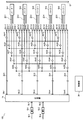
- FIG. 1 is a schematic view showing a gas branching device according to a first embodiment of the present invention.
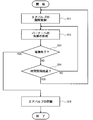
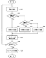
- FIG. 2 is a flowchart showing the operation of the gas branching apparatus according to the first embodiment of the present invention.
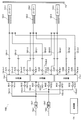
- FIG. 3 is a schematic view showing a gas branching device according to a third embodiment of the present invention.
- FIG. 4 is a flowchart showing the operation of the gas branching apparatus according to the third embodiment of the present invention.
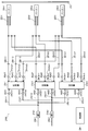
- FIG. 5 is a schematic view showing a gas branching device according to a sixth embodiment of the present invention.
- FIG. 6 is a flowchart showing the operation of the gas branching apparatus according to the sixth embodiment of the present invention.
- FIG. 7 is a schematic view showing a gas branch device according to a seventh embodiment of the present invention.
- FIG. 1 is a schematic view showing a gas branching apparatus according to the present embodiment.
- FIG. 2 is a flowchart showing the operation of the gas branching apparatus according to the present embodiment.
- the gas branching apparatus 100 branches and supplies gas to a plurality of burners 10-1 to 10-5, which are supply parts to which gas is to be supplied.
- the burners 10-1 to 10-5 are burners for manufacturing a glass fine particle deposit for optical fiber by the OVD method.
- the number of burners is not particularly limited as long as it is a plurality of two or more, but in the following, a case where five burners 10-1 to 10-5 are used will be described as an example.
- the burners 10-1 to 10-5 are made of quartz glass, for example, which are manufactured with the same design.
- Each of the burners 10-1 to 10-5 is configured to supply a plurality of gases in order to form a flame and introduce a raw material gas into the flame.
- the plurality of gases supplied to each of the burners 10-1 to 10-5 are, for example, hydrogen (H 2 ) gas, oxygen (O 2 ) gas, argon (Ar) gas, and source gas.
- the source gas includes SiCl 4 and the like. In the OVD method, these gases are used in each of the burners 10-1 to 10-5 to form an oxyhydrogen flame, and a raw material gas is introduced into the oxyhydrogen flame.
- the flow rate for supplying each gas to the burners 10-1 to 10-5 is not particularly limited, but the flow rate of the H 2 gas is, for example, 20000 to 40,000 sccm.
- the flow rate of the O 2 gas is, for example, 35000 to 40000 sccm.
- the flow rate of Ar gas is, for example, 3000 to 5000 sccm.
- the flow rate of the source gas is, for example, 3000 to 10000 sccm.
- the long rod-shaped core material 12 to which the flames of the burners 10-1 to 10-5 are blown is deposited with glass fine particles as a preform, for example, a glass rod.
- the core material 12 is held so that its longitudinal direction is horizontal. Further, the core material 12 is rotatably held with the central axis as a rotation axis.
- the length of the core material 12 is not particularly limited, but is, for example, several meters, more specifically, for example, 1 to 2 m.
- Burners 10-1 to 10-5 are arranged in the horizontal direction at equal intervals along the longitudinal direction of the long rod-shaped core member 12.
- five burners 10-1 to 10-5 are described as an example.
- the number of burners to be arranged for the core material 12 having a length of 1 to 2 m is 5 to 30. be able to.
- a plurality of flames by the burners 10-1 to 10-5 can be blown toward the core member 12 at equal intervals. Yes.
- the burners 10-1 to 10-5 are configured to be reciprocally movable within a predetermined range along the longitudinal direction of the core member 12.
- the core member 12 may be configured to be reciprocally movable along the longitudinal direction thereof.
- the gas branching apparatus 100 includes a flow divider 14 that branches a gas to be supplied to the plurality of burners 10-1 to 10-5.
- the gas branching apparatus 100 includes a piping system that supplies gas to the flow divider 14 and a piping system that connects the flow divider 14 and the plurality of burners 10-1 to 10-5. ing.
- the shunt 14 is made of, for example, metal, and includes two gas inlets 14i-1 and 14i-2 and a plurality of gas outlets 14o-1 having the same number as the plurality of burners 10-1 to 10-5. 14o-5.
- the plurality of gas outlets 14o-1 to 14o-5 are provided at regular intervals in a certain arrangement direction.
- the flow divider 14 is arranged so that the arrangement direction of the plurality of gas outlets 14o-1 to 14o-5 is horizontal, for example, similarly to the longitudinal direction of the core member 12.
- the volume of the flow divider 14 is not particularly limited, and can be selected according to gas supply conditions, for example, 1000 to 5000 cm 3 .
- gas supply conditions for example, 1000 to 5000 cm 3 .
- the number of gas inlets is not limited to two.
- the number of gas inlets may be one, or may be two or more, and can be appropriately changed according to the gas supply conditions, the volume of the flow divider 14, and the like.
- the gas branching apparatus 100 includes pipes 16-1 and 16-2 for supplying the same kind of gas to be supplied to the burners 10-1 to 10-5 to the flow divider 14.
- the upstream ends of the pipes 16-1 and 16-2 are connected to a gas supply source (not shown) to be supplied to the burners 10-1 to 10-5.
- the pipes 16-1 and 16-2 are provided with MFCs 18-1 and 18-2, respectively.
- the MFCs 18-1 and 18-2 can control the flow rate of the gas flowing in the pipes 16-1 and 16-2 toward the flow divider 14, respectively.
- the downstream ends of the pipes 16-1 and 16-2 are connected to the two gas introduction ports 14i-1 and 14i-2 of the flow divider 14, respectively.
- the flow divider 14 is arranged upstream of the plurality of pipes 20-1 to 20-5.
- the upstream ends of the pipes 20-1 to 20-5 are connected to the gas outlets 14o-1 to 14o-5 of the flow divider 14, respectively.
- the shunt 14 is designed so that the gas branching ratios to the plurality of gas outlets 14o-1 to 14o-5 are equal.
- the shunt 14 is configured so that the gas introduced into the shunt 14 from the pipes 16-1 and 16-2 is supplied from the plurality of gas outlets 14o-1 to 14o-5 with equal branch ratios, respectively. It is designed to be derived at 20-5.
- the pipes 20-1 to 20-5 are branched into the same number of branch pipes as the number of the burners 10-1 to 10-5 on the downstream end side. That is, the pipe 20-1 is branched into branch pipes 20-1-1 to 20-1-5 on the downstream end side.
- the pipe 20-2 is branched into branch pipes 20-2-1 to 20-2-5 on the downstream end side thereof.
- the pipe 20-3 is branched into branch pipes 20-3-1 to 20-3-5 on the downstream end side.
- the pipe 20-4 is branched into branch pipes 20-4-1 to 20-4-5 on the downstream end side thereof.
- the pipe 20-5 is branched into branch pipes 20-5-1 to 20-5-5 on the downstream end side.
- Each of the branch pipes 20-1 to 20-5 is provided with an air valve that opens and closes the branch pipe. That is, air valves AV11, AV12, AV13, AV14, and AV15 are provided in the branch pipes 20-1-1 to 20-1-5, respectively.
- the branch pipes 20-2-1 to 20-2-5 are provided with air valves AV21, AV22, AV23, AV24, and AV25, respectively.
- Branch valves 20-3-1 to 20-3-5 are provided with air valves AV31, AV32, AV33, AV34, and AV35, respectively.
- the branch pipes 20-4-1 to 20-4-5 are provided with air valves AV41, AV42, AV43, AV44, and AV45, respectively.
- Branch valves 20-5-1 to 20-5-5 are provided with air valves AV51, AV52, AV53, AV54, and AV55, respectively.
- these air valves may be expressed as air valves AVxy (where x is an integer satisfying 1 ⁇ x ⁇ 5 and y is an integer satisfying 1 ⁇ y ⁇ 5).
- the upstream of the pipe 22-1 The ends are connected in common.
- the branch pipes 20-1-2, 20-2-2, 20-3-2, 20-4-2, and 20-5-2 which have different branch source pipes, upstream of the pipe 22-2
- the ends are connected in common.
- branch pipes 20-1-3, 20-2-3, 20-3-3, 20-4-3, and 20-5-3 which have different branch source pipes, upstream of the pipe 22-3
- the ends are connected in common.
- branch pipes 20-1-4, 20-2-4, 20-3-4, 20-4-4, and 20-5-4 having different branch source pipes upstream of the pipe 22-4
- the ends are connected in common.
- branch pipes 20-1-5, 20-2-5, 20-3-5, 20-4-5, and 20-5-5, which have different pipes from each other upstream of the pipe 22-5
- the ends are connected in common.
- the downstream end of the pipe 22-1 is connected to the burner 10-1, and gas is supplied from the pipe 22-1 to the burner 10-1.
- the downstream end of the pipe 22-2 is connected to the burner 10-2, and gas is supplied from the pipe 22-2 to the burner 10-2.
- the downstream end of the pipe 22-3 is connected to the burner 10-3, and gas is supplied from the pipe 22-3 to the burner 10-3.
- the downstream end of the pipe 22-4 is connected to the burner 10-4, and gas is supplied from the pipe 22-4 to the burner 10-4.
- the downstream end of the pipe 22-5 is connected to the burner 10-5, and gas is supplied from the pipe 22-5 to the burner 10-5.
- the gas branching apparatus 100 further includes a control unit 24 that controls opening and closing of the air valve AVxy.
- the control unit 24 has a CPU (not shown) that executes processing such as various calculations, control, and discrimination.
- the control unit 24 includes a ROM (not shown) that stores various control programs executed by the CPU, a database referred to by the CPU, and the like.
- the control unit 24 has a RAM (not shown) that temporarily stores data being processed by the CPU, input data, and the like.
- the control unit 24 controls the opening / closing of the air valve AVxy so that the opening / closing state of the air valve AVxy is randomly switched a plurality of times while the preform is manufactured using the flames of the burners 10-1 to 10-5.
- the control unit 24 controls the opening / closing of the air valve AVxy so that the following conditions (I) and (II) are satisfied.
- (I) For each of x 1 to 5, any one of the air valves AVx1, AVx2, AVx3, AVx4, and AVx5 is opened, and the rest is closed.
- (II) For each of y 1 to 5, any one of the air valves AV1y, AV2y, AV3y, AV4y, AV5y is opened, and the rest is closed.
- the control unit 24 executes switching of the open / closed state of the air valve AVxy at predetermined time intervals.
- the time interval is not particularly limited, but can be set to 1 to 10 minutes, for example.
- control unit 24 switches the open / close state of the air valve AVxy so that the plurality of gas outlets 14o-1 to 14o-5 and the plurality of burners 10-1 to 10- 5 is connected corresponding to 1: 1. Further, the gas outlets 14o-1 to 14o-5 of the flow divider 14 connected to the burners 10-1 to 10-5 are switched randomly.
- the flow divider 14 is designed so that the gas branch ratios to the plurality of gas outlets 14o-1 to 14o-5 are equal. Further, it is designed so that the difference in piping resistance from the plurality of gas outlets 14o-1 to 14o-5 to the burners 10-1 to 10-5 is minimized.
- the branching ratio of the flow divider 14 may not be completely uniform due to processing accuracy and changes over time. Further, due to processing accuracy and changes over time, there may be a difference in piping resistance from the plurality of gas outlets 14o-1 to 14o-5 to the burners 10-1 to 10-5. Further, although the burners 10-1 to 10-5 are manufactured with the same design, there are individual differences due to processing accuracy and changes with time.
- the control unit 24 switches the open / close state of the air valve AVxy so that the gas outlet 14o ⁇ of the flow divider 14 connected to the burners 10-1 to 10-5. 1 to 14o-5 are randomly switched.
- variation in a member or components can be reduced. Therefore, according to the present embodiment, it is possible to supply gas to the plurality of burners 10-1 to 10-5 with high uniformity while reducing the influence due to variations in members or parts.
- the operation of the gas branching device 100 is started, and gas is introduced from the pipes 16-1 and 16-2 toward the flow divider 14. While the gas is introduced from the pipes 16-1 and 16-2, the MFCs 18-1 and 18-2 control the flow rate of the gas flowing through the pipes 16-1 and 16-2, respectively.
- opening / closing of the air valve AVxy is controlled by the control unit 24 (step S11).
- the open / closed state of the air valve AVxy is set to an open / closed state that satisfies the above conditions (I) and (II).
- the control unit 24 When controlling the opening / closing of the air valve AVxy, the control unit 24 generates, for example, a random number or a pseudo-random number, selects an air valve to be opened based on the generated random number or pseudo-random number, and opens the remaining air valves.
- step S12 gas is supplied to each of the plurality of burners 10-1 to 10-5 (step S12). Further, other gases used for manufacturing the glass fine particle deposit are similarly supplied to the plurality of burners 10-1 to 10-5.
- each of the burners 10-1 to 10-5 to which gas is supplied as described above a flame is formed by the fuel gas of the supplied gas, and the source gas of the supplied gas is in the flame. To be introduced. In this way, the flame containing the raw material is blown toward the core material 12 that rotates around the central axis. As a result, glass fine particles, which are preforms of the optical fiber, are deposited on the core material 12. During this time, the plurality of burners 10-1 to 10-5 may be reciprocated along the longitudinal direction of the core member 12.
- the deposition weight of the glass particulates deposited on the core material 12 is monitored, and the deposition of the glass particulates is terminated based on the monitored deposition weight. It is determined whether or not (step S13).
- step S14 it is determined whether or not a time interval for switching the open / close state of the air valve AVxy has passed (step S14). ).
- step S14 When the time interval for switching the open / closed state of the air valve AVxy has not elapsed (NO in step S14), the process returns to step S12, and the deposition of glass particles is continued while supplying each gas as it is.
- step S14 when the time interval for switching the open / close state of the air valve AVxy has elapsed (step S14, YES), the process returns to step S11, and the control unit 24 again controls the open / close of the air valve AVxy.
- the air valve AVxy is randomly switched from the open / closed state to the open / closed state satisfying the above conditions (I) and (II), and the deposition of glass particles is continued while supplying each gas.
- control unit 24 When controlling the opening / closing of the air valve AVxy, the control unit 24 generates, for example, a random number or a pseudo-random number, selects an air valve to be opened based on the generated random number or pseudo-random number, and opens the remaining air valves. And
- the gas outlet 14o-1 of the flow divider 14 connected to the burners 10-1 to 10-5 is obtained by the switching of the open / close state of the air valve AVxy by the control unit 24 at random. ⁇ 14o-5 are randomly switched. Thereby, the influence by the dispersion
- switching of the open / closed state of the air valve AVxy is based on the integrated time of the time during which the gas derived from the gas outlets 14o-1 to 14o-5 is supplied to the burners 10-1 to 10-5. It is preferable to carry out so that it is equal between 1 and 10-5. As a result, it is possible to further reduce the influence of variations in members or parts due to processing accuracy and changes over time, and it is possible to supply gas to the plurality of burners 10-1 to 10-5 with higher uniformity.
- step S13 when the deposition weight of the glass particles is a predetermined weight and the deposition is finished (step S13, YES), the control unit 24 closes all the air valves AVxy (step S15). In this way, the deposition of the glass fine particles on the core material 12 is finished, and a glass fine particle deposit that is a glass fine particle deposit is obtained.
- a preform is obtained by performing dehydration and sintering in the furnace on the glass fine particle deposit obtained as described above.
- gas can be supplied to a plurality of supplied parts with high uniformity.
- the opening / closing of the air valve AVxy is controlled so as to randomly switch the opening / closing state of the air valve AVxy a plurality of times.
- the opening / closing control of the air valve AVxy is not limited to the case where the opening / closing state of the air valve AVxy is randomly switched a plurality of times.
- the opening / closing of the air valve AVxy may be controlled so as to regularly switch the opening / closing state of the air valve AVxy multiple times.
- the open / close of the air valve Axy in each of the following valve groups is controlled in synchronization as follows.
- the valve groups of the air valves AV11 to AV15 are repeatedly opened in the order of the air valve AV11, the air valve AV12, the air valve AV13, the air valve AV14, and the air valve AV15. On the other hand, the remaining air valves other than the opened air valve are closed.
- the valve groups of the air valves AV21 to AV25 are repeatedly opened in the order of the air valve AV22, the air valve AV23, the air valve AV24, the air valve AV25, and the air valve AV21. On the other hand, the remaining air valves other than the opened air valve are closed.
- valve groups of the air valves AV31 to AV35 are repeatedly opened in the order of the air valve AV33, the air valve AV34, the air valve AV35, the air valve AV31, and the air valve AV32.
- the remaining air valves other than the opened air valve are closed.
- valve groups of the air valves AV41 to AV45 are repeatedly opened in the order of the air valve AV44, the air valve AV45, the air valve AV41, the air valve AV42, and the air valve AV43.
- the remaining air valves other than the opened air valve are closed.
- the valve groups of the air valves AV51 to AV55 are repeatedly opened in the order of the air valve AV55, the air valve AV51, the air valve AV52, the air valve AV53, and the air valve AV54. On the other hand, the remaining air valves other than the opened air valve are closed.
- the opening / closing state of the air valve AVxy can be controlled so as to regularly switch the opening / closing state of the air valve AVxy to an opening / closing state satisfying the above conditions (I) and (II).
- the gas outlet ports 14o-1 to 14o-5 of the flow divider 14 connected to the burners 10-1 to 10-5 are switched regularly. Even by such regular switching, it is possible to reduce the influence due to variations in members or parts due to processing accuracy and changes over time. Therefore, according to the present embodiment, it is possible to supply gas to the plurality of burners 10-1 to 10-5 with high uniformity while reducing the influence due to variations in members or parts.
- switching of the open / closed state of the air valve AVxy is performed by integrating the time during which the gas derived from the gas outlets 14o-1 to 14o-5 is supplied to the burners 10-1 to 10-5.
- the burners 10-1 to 10-5 are preferably made to be equal.
- the present invention is not limited to the first and second embodiments, and various modifications can be made.
- the case where gas is branched and supplied to the five burners 10-1 to 10-5 has been described as an example.
- the number of burners is two or more. It is not particularly limited.
- the shunt When the gas is branched and supplied to the first to Nth (where N is an integer equal to or greater than 2) burners, the shunt has first to Nth gas outlets through which the gas is led out. It is assumed that the gas branching ratio to the 1st to Nth gas outlets is designed to be uniform.
- the upstream ends of the first to Nth pipes are connected to the first to Nth gas outlets, respectively.
- Each of the first to Nth pipes is branched to the first to Nth branch pipes on the downstream end side.
- the i-th branch pipes of the first to N-th pipes are connected in common to the i-th burner, respectively, and the i-th pipes of the first to N-th pipes are connected.
- Each branch pipe is provided with a valve.
- the control unit may control opening and closing of the valve so that the following first condition and second condition are satisfied. That is, the first condition is that, for each integer j that is greater than or equal to 1 and less than or equal to N, one of the N valves provided in the first to Nth branch pipes of the jth pipe is opened, The rest is closed.
- the second condition is that, for each integer k of 1 or more and N or less, one of N valves provided in the kth branch pipe of the first to Nth pipes is opened, The rest is closed.
- the burners 10-1 to 10-5 have been described as examples of the plurality of supplied parts to which the gas is supplied.
- the supplied parts are not limited to the burners.
- the supplied part may be any part that performs some processing such as manufacturing of a product and processing of a processed product using the supplied gas.
- the case where the burners 10-1 to 10-5 as the supplied parts are arranged along the longitudinal direction of the core 12 which is a long object is described as an example.
- the plurality of supplied parts are not necessarily arranged along the longitudinal direction of the object.
- the case where the air valve AVxy is used has been described as an example.
- various valves that can be opened and closed by the control unit 24 can be used instead of the air valve.
- an electromagnetic valve or the like can be used instead of the air valve.
- the aspect holding the core material 12 is not limited to this. Absent.
- the core material 12 may be held so that its longitudinal direction is vertical.
- the burners 10-1 to 10-5 can be arranged at equal intervals along the longitudinal direction of the core member 12 arranged vertically.
- the shunt 14 may be arranged so that the arrangement direction of the plurality of gas outlets 14o-1 to 14o-5 is horizontal as described above, or the plurality of gas outlets 14o-1 to 14o-. It can also arrange
- first and second embodiments can be applied when no shunt is used or when the branching ratio of the shunt is not uniform.
- FIG. 3 is a schematic view showing the gas branching apparatus according to the present embodiment.
- FIG. 4 is a flowchart showing the operation of the gas branching apparatus according to the present embodiment.
- the gas branching apparatus 1100 branches and supplies the gas to a plurality of burners 110-1 to 110-3, which are supplied parts to which the gas is to be supplied.
- the burners 110-1 to 110-3 are burners for producing a glass particle deposit for optical fiber by the OVD method.
- the number of burners is not particularly limited as long as it is a plurality of two or more. However, a case where three burners 110-1 to 110-3 are used will be described below as an example.
- the burners 110-1 to 110-3 are made of quartz glass, for example, which are manufactured with the same design.
- Each of the burners 110-1 to 110-3 is configured to supply a plurality of gases in order to form a flame and introduce a raw material gas into the flame.
- the plurality of gases supplied to each of the burners 110-1 to 110-3 are, for example, hydrogen (H 2 ) gas, oxygen (O 2 ) gas, argon (Ar) gas, and source gas.
- the source gas includes SiCl 4 and the like. In the OVD method, these gases are used in each of the burners 110-1 to 110-3 to form an oxyhydrogen flame, and a raw material gas is introduced into the oxyhydrogen flame.
- the flow rate of supplying each gas to the burners 110-1 to 110-3 is not particularly limited, but the flow rate of the H 2 gas is, for example, 20000 to 40000 sccm.
- the flow rate of the O 2 gas is, for example, 35000 to 40000 sccm.
- the flow rate of Ar gas is, for example, 3000 to 5000 sccm.
- the flow rate of the source gas is, for example, 3000 to 10000 sccm.
- the long rod-shaped core material 112 to which the flames of the burners 110-1 to 110-3 are blown is deposited with glass fine particles as a preform, for example, a glass rod.
- the core material 112 is held so that its longitudinal direction is vertical. Further, the core material 112 is rotatably held with the central axis as a rotation axis.
- the length of the core material 112 is not particularly limited, but is several meters, for example, more specifically, 1-2 m, for example.
- the core material 112 When the core material 112 is enlarged and becomes long or heavy, if the core material 112 is held so that its longitudinal direction is horizontal, the core material 112 is bent. As a result, it becomes difficult to produce a glass particulate deposit while ensuring uniformity in the longitudinal direction. In this embodiment, since the core material 112 is held so that its longitudinal direction is vertical, the occurrence of bending in the core material 112 can be suppressed.
- the burners 110-1 to 110-3 are arranged in the vertical direction at equal intervals along the longitudinal direction of the long rod-shaped core material 112. In this embodiment, three burners 110-1 to 110-3 are described as an example. For example, the number of burners to be arranged for the core material 112 having a length of 1 to 2 m is 5 to 30. be able to. Thus, by arranging the burners 110-1 to 110-3 at equal intervals, a plurality of flames by the burners 110-1 to 110-3 can be blown toward the core material 112 at equal intervals. Yes.
- the burners 110-1 to 110-3 are configured to be able to reciprocate within a predetermined range along the longitudinal direction of the core material 112.
- the core material 112 may be configured to reciprocate along the longitudinal direction thereof.
- the gas branching apparatus 1100 includes a plurality of flow dividers 114-1 to 114-3 that branch the gas to be supplied to the plurality of burners 110-1 to 110-3. Further, the gas branching apparatus 1100 according to the present embodiment includes a piping system that supplies gas to the plurality of flow dividers 114-1 to 114-3, a plurality of flow dividers 114-1 to 114-3, and a plurality of burners 110-1. To 110-3.
- the current dividers 114-1 to 114-3 are each made of, for example, metal, and are manufactured with the same design.
- the shunt 114-1 has two gas inlets 114-1i-1 and 114-1i-2 and a plurality of gas outlets 114-1o-1 equal in number to the plurality of burners 110-1 to 110-3. 114-1o-3.
- the plurality of gas outlets 114-1o-1 to 114-1o-3 are provided side by side at regular intervals in a certain arrangement direction.
- the shunt 114-2 includes two gas inlets 114-2i-1 and 114-2i-2 and a plurality of gas outlets 114-2o-1 having the same number as the plurality of burners 110-1 to 110-3. 114-2o-3.
- the plurality of gas outlets 114-2o-1 to 114-2o-3 are provided at equal intervals in a certain arrangement direction.
- the shunt 114-3 has two gas inlets 114-3i-1 and 114-3i-2 and a plurality of gas outlets 114-3o-1 having the same number as the plurality of burners 110-1 to 110-3. 114-3o-3.
- the plurality of gas outlets 114-3o-1 to 114-3o-3 are provided at equal intervals in a certain arrangement direction.
- the shunts 114-1 to 114-3 are arranged vertically in this order from the upper side to the lower side.
- a plurality of gas outlets 114-1o-1 to 114-1o-3, 114-2o-1 to 114-2o-3, 114-3o The arrangement direction of ⁇ 1 to 114-3o-3 is vertical, similar to the longitudinal direction of the core material 112.
- the plurality of gas outlets of the flow dividers 114-1 to 114-3 have different height positions, and there is a difference in height between them.
- the gas outlet 114-1o-1 is located at the upper stage
- the gas outlet 114-1o-2 is located at the middle stage
- the gas outlet 114-1o-3 is located at the lower stage.
- the gas outlet 114-2o-1 is located in the upper stage
- the gas outlet 114-2o-2 is located in the middle stage
- the gas outlet 114-2o-3 is located in the lower stage.
- the gas outlet 114-3o-1 is located at the upper stage
- the gas outlet 114-3o-2 is located at the middle stage
- the gas outlet 114-3o-3 is located at the lower stage.
- each of the flow dividers 114-1 to 114-3 is not particularly limited and can be selected according to the gas supply conditions and the like, but is, for example, 1000 to 5000 cm 3 . Further, although the case where each of the flow dividers 114-1 to 114-3 has two gas inlets has been described, the number of gas inlets is not limited to two. The number of gas inlets may be one or a plurality of two or more, and can be appropriately changed according to the gas supply conditions, the volumes of the flow dividers 114-1 to 114-3, and the like. .
- the gas branching apparatus 1100 includes pipes 116-1 and 116-2 for supplying the same type of gas to be supplied to the burners 110-1 to 110-3 to the flow dividers 114-1 to 114-3. is doing.
- the upstream ends of the pipes 116-1 and 116-2 are connected to a gas supply source (not shown) to be supplied to the burners 110-1 to 110-3.
- the pipes 116-1 and 116-2 are provided with MFCs 118-1 and 118-2, respectively.
- the MFCs 118-1 and 118-2 can control the flow rate of the gas flowing in the pipes 116-1 and 116-2 toward the flow dividers 114-1 to 114-3, respectively.
- the pipes 116-1 and 116-2 are branched into the same number of branch pipes as the number of the flow dividers 114-1 to 114-3 on the downstream end side. That is, the pipe 116-1 is branched into branch pipes 116-1-1 to 116-1-3 on the downstream end side.
- the pipe 116-2 is branched into branch pipes 116-2-1 to 116-2-3 on the downstream end side thereof.
- the downstream ends of the branch pipes 116-1-1 and 116-2-1 are connected to the two gas inlets 114-1i-1 and 114-1i-2 of the flow divider 114-1, respectively.
- the downstream ends of branch pipes 116-1-2 and 116-2-2 are connected to the two gas introduction ports 114-2i-1 and 114-2i-2 of the flow divider 114-2, respectively.
- the downstream ends of branch pipes 116-1-3 and 116-2-3 are connected to the two gas introduction ports 114-3i-1 and 114-3i-2 of the flow divider 114-3, respectively.
- the branch pipes of the pipes 116-1 and 116-2 are each provided with an air valve for opening and closing the branch pipe. That is, air valves BV11 and BV12 are provided in the branch pipes 116-1-1 and 116-2-1, respectively. Branch valves 116-1-2 and 116-2-2 are provided with air valves BV21 and BV22, respectively. Air valves BV31 and BV32 are provided in the branch pipes 116-1-3 and 116-2-3, respectively. In the following description, these air valves may be expressed as air valves BVxy (where x is an integer satisfying 1 ⁇ x ⁇ 3 and y is 1 or 2).
- the upstream ends of the pipes 120-1-1 to 120-1-3 are connected to the gas outlets 114-1o-1 to 114-1o-3 of the flow divider 114-1, respectively.
- the shunt 114-1 is designed so that the gas branch ratios to the plurality of gas outlets 114-1o-1 to 114-1o-3 are equal. That is, in the flow divider 114-1, the gas introduced into the flow divider 114-1 from the branch pipes 116-1-1 and 116-2-1 is supplied to the plurality of gas outlets 114-1o-1 to 114-1o-. 3 is designed to be led out to the pipes 120-1-1 to 120-1-3 at equal branching ratios.
- the piping 120-1-1 to 120-1-3 are provided with check valves (check valves) CV11, CV12, and CV13, respectively.
- the check valves CV11, CV12, and CV13 prevent the backflow of gas from the downstream side to the upstream side of the flow divider 114-1 in the pipes 120-1-1 to 120-1-3, respectively.
- air valves that open and close in synchronization with the air valves BV11 and BV12 on the gas introduction side may be provided.
- the upstream ends of the pipes 120-2-1 to 120-2-3 are connected to the gas outlets 114-2o-1 to 114-2o-3 of the flow divider 114-2, respectively.
- the shunt 114-2 is designed so that the gas branch ratios to the plurality of gas outlets 114-2o-1 to 114-2o-3 are equal. That is, in the flow divider 114-2, the gas introduced from the branch pipes 116-1-2 and 116-2-2 into the flow divider 114-2 is supplied to the gas outlets 114-2o-1 to 114-2o-. 3 is designed to be led out to the pipes 120-2-1 to 120-2-3 at an equal branching ratio.
- Check valves CV21, CV22, and CV23 are provided in the pipes 120-2-1 to 120-2-3, respectively.
- the check valves CV21, CV22, and CV23 prevent backflow of gas from the downstream side to the upstream side of the flow divider 114-2 in the pipes 120-2-1 to 120-2-3, respectively.
- air valves that open and close in synchronization with the air valves BV21 and BV22 on the gas introduction side may be provided.
- the upstream ends of the pipes 120-3-1 to 120-3-3 are connected to the plurality of gas outlets 114-3o-1 to 114-3o-3 of the flow divider 114-3, respectively.
- the shunt 114-3 is designed so that the gas branch ratios to the plurality of gas outlets 114-3o-1 to 114-3o-3 are equal. That is, in the flow divider 114-3, the gas introduced into the flow divider 114-3 from the branch pipes 116-1-3 and 116-2-3 is supplied to the gas outlets 114-3o-1 to 114-3o-. 3 is designed to be led out to the pipes 120-3-1 to 120-3-3 at an equal branching ratio.
- Check valves CV31, CV32, and CV33 are provided on the pipes 120-3-1 to 120-3-3, respectively.
- the check valves CV31, CV32, and CV33 prevent backflow of gas from the downstream side to the upstream side of the flow divider 114-3 in the pipes 120-3-1 to 120-3-3, respectively.
- air valves that open and close in synchronization with the air valves BV31 and BV32 on the gas introduction side may be provided.
- check valve may be expressed as check valve CVmn (where m is an integer that satisfies 1 ⁇ m ⁇ 3, and n is an integer that satisfies 1 ⁇ n ⁇ 3). .
- the upstream end of the pipe 122-1 is commonly connected to the downstream ends of the pipes 120-1-1, 120-2-2, and 120-3-3.
- These pipes 120-1-1, 120-2-2, and 120-3-3 are connected to gas outlets having different height differences in the flow divider. That is, the pipe 120-1-1 is connected to the upper gas outlet 114-1o-1, the pipe 120-2-2 is connected to the middle gas outlet 114-2o-2, and the pipe 120-3-3 is connected. Is connected to the lower gas outlet 114-3o-3.
- the upstream end of the pipe 122-2 is commonly connected to the downstream ends of the pipes 120-1-3, 120-2-1, 120-3-2.
- These pipes 120-1-3, 120-2-1 and 120-3-2 are connected to gas outlets having different height differences in the flow divider. That is, the pipe 120-1-3 is connected to the lower gas outlet 114-1o-3, the pipe 120-2-1 is connected to the upper gas outlet 114-2o-1, and the pipe 120-3-2 is connected. Is connected to the middle gas outlet 114-3o-2.
- the upstream end of the pipe 122-3 is commonly connected to the downstream ends of the pipes 120-1-2, 120-2-3, and 120-3-1.
- These pipes 120-1-2, 120-2-3, and 120-3-1 are connected to gas outlets having different height differences in the flow divider. That is, the pipe 120-1-2 is connected to the middle gas outlet 114-1o-2, the pipe 120-2-3 is connected to the lower gas outlet 114-2o-3, and the pipe 120-3-1 is connected. Is connected to the upper gas outlet 114-3o-1.
- the downstream end of the pipe 122-1 is connected to the burner 110-1, and gas is supplied from the pipe 122-1 to the burner 110-1.
- the downstream end of the pipe 122-2 is connected to the burner 110-2, and gas is supplied from the pipe 122-2 to the burner 110-2.
- the downstream end of the pipe 122-3 is connected to the burner 110-3, and gas is supplied from the pipe 122-3 to the burner 110-3.
- the plurality of gas outlets of each of the plurality of flow dividers 114-1 to 114-3 are connected to any of the plurality of burners 110-1 to 110-3 by a pipe 1: 1. That is, the gas outlet 114-1o-1 of the flow divider 114-1 is connected to the burner 110-1 via the pipes 120-1-1 and 122-1. The gas outlet 114-1o-2 of the flow divider 114-1 is connected to the burner 110-3 via pipes 120-1-2 and 122-3. The gas outlet 114-1o-3 of the flow divider 114-1 is connected to the burner 110-2 via pipes 120-1-3 and 122-2. The gas outlet 114-2o-1 of the flow divider 114-2 is connected to the burner 110-2 via pipes 120-2-1 and 122-2.
- the gas outlet 114-2o-2 of the flow divider 114-2 is connected to the burner 110-1 via pipes 120-2-2 and 122-1.
- the gas outlet 114-2o-3 of the flow divider 114-2 is connected to the burner 110-3 via pipes 120-2-3 and 122-3.
- the gas outlet 114-3o-1 of the flow divider 114-3 is connected to the burner 110-3 via pipes 120-3-1 and 122-3.
- the gas outlet 114-3o-2 of the flow divider 114-3 is connected to the burner 110-2 via pipes 120-3-2 and 122-2.
- the gas outlet 114-3o-3 of the flow divider 114-3 is connected to the burner 110-1 via pipes 120-3-3 and 122-1.
- the gas branching apparatus 1100 further includes a control unit 124 that controls opening and closing of the air valve BVxy.
- the control unit 124 includes a CPU (not shown) that executes various processes such as calculation, control, and determination.
- the control unit 124 includes a ROM (not shown) that stores various control programs executed by the CPU, a database referred to by the CPU, and the like.
- the control unit 124 has a RAM (not shown) that temporarily stores data being processed by the CPU, input data, and the like.
- the control unit 124 uses a plurality of current dividers 114-1 to 114-3 for dividing the gas during the production of the glass particulate deposit using the flames of the burners 110-1 to 110-3.
- the opening and closing of the air valve BVxy is controlled so as to switch randomly.
- the control unit 124 controls the opening and closing of the air valves BV11 and BV12 with respect to the flow divider 114-1 in synchronization. Further, the opening and closing of the air valves BV21 and BV22 with respect to the flow divider 114-2 are controlled in synchronization. Further, the opening and closing of the air valves BV31 and BV32 with respect to the flow divider 114-3 are controlled in synchronization.
- control unit 124 opens one of the set of the air valves BV11 and BV12, the set of the air valves BV21 and BV22, and the set of the air valves BV31 and BV32 that are controlled in synchronization with each other, and sets the remaining sets. Closed.
- the control unit 124 executes switching of the shunt used above at a predetermined time interval.
- the time interval is not particularly limited, but can be set to 1 to 10 minutes, for example.
- any of the flow dividers 114-1 to 114-3 is used to branch the gas supplied to the plurality of burners 110-1 to 110-3 by switching the flow divider by the control unit 124. One is used and the shunt used is switched randomly.
- the height position of the gas outlet of the shunt that supplies gas to the plurality of burners 110-1 to 110-3 will be different.
- the burner 110-1 has an upper gas outlet 114-1o-1 and the burner 110-2 has a lower gas outlet 114-1o-3.
- 110-3 is supplied with gas from the middle gas outlet 114-1o-2.
- the burner 110-1 has a middle gas outlet 114-2o-2, and the burner 110-2 has an upper gas outlet 114-2o-1 through the burner 110-.
- 3 is supplied with gas from the lower gas outlet 114-2o-3.
- the burner 110-1 has a lower gas outlet 114-3o-3
- the burner 110-2 has an intermediate gas outlet 114-3o-2. 3 is supplied with gas from the upper gas outlet 114-3o-1.
- the flow divider When supplying gas to a plurality of burners by diverting a gas by using a flow divider when producing a glass fine particle deposit, if the glass fine particle deposit to be produced increases in size, the flow divider itself increases in size and the number of branches by the flow divider increases. Need arises. Further, if the core material is held so that the longitudinal direction thereof is horizontal, the core material and the glass fine particle deposit increase in weight, which causes bending. In order to suppress such bending, it is necessary to hold the core material so that its longitudinal direction is vertical. In this case, the arrangement direction of the plurality of gas outlets is vertical in order to minimize the pipe distance difference between the plurality of gas outlets of the flow divider and the plurality of burners and the pipe resistance difference associated therewith. Thus, it is necessary to arrange the shunt vertically.
- the control unit 124 randomly switches the flow divider used for the gas branching to any one of the flow dividers 114-1 to 114-3. If the shunt used is different, the height position of the gas outlet of the shunt that supplies gas to the plurality of burners 110-1 to 110-3 is different as described above. Thereby, since the influence by the gravity with respect to the branch of the gas by the above shunt is canceled, the influence by the gravity can be reduced.
- each of the plurality of flow dividers 114-1 to 114-3 is designed so that the branching ratio of the gas to the plurality of gas outlets is equalized. Further, it is designed so that the difference in piping resistance from the plurality of gas outlets to the burners 110-1 to 110-3 is minimized.
- the branching ratios of the shunts 114-1 to 114-3 may not be completely equal due to processing accuracy and changes over time.
- the burners 110-1 to 110-3 are manufactured with the same design, there are individual differences due to processing accuracy and changes with time.
- the flow divider used for the gas branching is randomly switched by the control unit 124.
- the present embodiment it is possible to supply gas to the plurality of burners 110-1 to 110-3 with high uniformity while reducing the influence of gravity and the influence of variations in members or parts.
- the same gas supply state as before replacement can be reproduced with high reproducibility, and glass particle deposition with excellent uniformity and stability in the longitudinal direction.
- the body can be manufactured with high reproducibility.
- the operation of the gas branching device 1100 is started, and gas is introduced from the pipes 116-1 and 116-2 toward the flow dividers 114-1 to 114-3. While introducing the gas from the pipes 116-1 and 116-2, the MFCs 118-1 and 118-2 control the flow rate of the gas flowing through the pipes 116-1 and 116-2, respectively.
- the controller 124 controls the opening and closing of the air valve BVxy.
- one of the set of air valves BV11 and BV12, the set of air valves BV21 and BV22, and the set of air valves BV31 and BV32 is set in an open state, and the remaining set is set in a closed state.
- the control unit 124 When controlling the opening / closing of the air valve BVxy, the control unit 124 generates, for example, a random number or a pseudo-random number, selects a set of air valves to be opened based on the generated random number or the pseudo-random number, and opens the remaining air valves. The pair is closed.
- any one of the flow dividers 114-1 to 114-3 is set as a flow divider used for gas branching (step S111).
- the gas is branched by the set flow divider and the gas is supplied to each of the plurality of burners 110-1 to 110-3 (step S112). Since the check valves CVmn are respectively provided on the gas outlet side for the flow dividers 114-1 to 114-3, the gas does not flow back to the flow dividers that are not used for the gas branching. Further, other gases used for manufacturing the glass fine particle deposit are similarly supplied to the plurality of burners 110-1 to 110-3.
- each of the burners 110-1 to 110-3 to which gas is supplied as described above a flame is formed by the fuel gas of the supplied gas, and the source gas of the supplied gas is in the flame. To be introduced. In this way, the flame containing the raw material is blown toward the core material 112 that rotates around the central axis. As a result, glass fine particles, which are preforms of the optical fiber, are deposited on the core material 112. During this time, the plurality of burners 110-1 to 110-3 may be reciprocated along the longitudinal direction of the core material 112.
- the deposition weight of the glass particulates deposited on the core material 112 is monitored, and the deposition of the glass particulates is terminated based on the monitored deposition weight. It is determined whether or not (step S113).
- Step S114 When the deposition weight of the glass fine particles is less than the predetermined weight and the deposition is continued without finishing (NO in step S113), it is determined whether or not the time interval for switching the shunt used for the gas branching has elapsed. (Step S114).
- step S114 If the time interval for switching the shunt used for gas branching has not elapsed (step S114, NO), the process returns to step S112, and the deposition of glass particles is continued by supplying each gas as it is.
- step S114 when the time interval for switching the shunt used for the gas branching has elapsed (step S114, YES), the process returns to step S111, and the controller 124 controls the opening / closing of the air valve BVxy again.
- the controller 124 controls the opening / closing of the air valve BVxy again.
- one of the set of air valves BV11 and BV12, the set of air valves BV21 and BV22, and the set of air valves BV31 and BV32 is set in an open state, and the remaining set is set in a closed state.
- the control unit 124 When controlling the opening / closing of the air valve BVxy, the control unit 124 generates, for example, a random number or a pseudo-random number, selects a set of air valves to be opened based on the generated random number or the pseudo-random number, and opens the remaining air valves. The pair is closed.
- the shunt used for the gas branching is switched randomly, and the deposition of the glass particles is continued while supplying each gas.
- the height position of the gas outlet port of the flow divider connected to the burners 110-1 to 110-3 is randomly changed by the random switching of the flow divider by the control unit 124. Can be switched. Thereby, the influence by gravity with respect to the branching ratio of a shunt can be reduced. Moreover, the influence by the dispersion
- switching of the shunt used for the gas branching is preferably performed so that the accumulated time of the time used for each of the shunts 114-1 to 114-3 is equal to each other.
- switching of the shunt used for the gas branching is preferably performed so that the accumulated time of the time used for each of the shunts 114-1 to 114-3 is equal to each other.
- step S113 when the deposition weight of the glass particles is a predetermined weight and the deposition is finished (step S113, YES), the control unit 124 causes all the air valves BVxy to be closed (step S115). In this way, the deposition of the glass fine particles on the core material 112 is finished, and a glass fine particle deposit body which is a glass fine particle deposit is obtained.
- a preform is obtained by performing dehydration and sintering in the furnace on the glass fine particle deposit obtained as described above.
- gas can be supplied to a plurality of supplied parts with high uniformity and high reproducibility.
- the opening / closing of the air valve BVxy is controlled so as to randomly switch the shunt used for gas branching a plurality of times.
- the opening / closing control of the air valve BVxy is not limited to the case where the shunt used for the gas branching is randomly switched a plurality of times.
- the opening / closing of the air valve BVxy may be controlled so as to regularly switch the shunt used for gas branching a plurality of times.
- the set of air valves BV11 and BV12, the set of air valves BV21 and BV22, and the set of air valves BV31 and BV32 Repeatedly open.
- the remaining groups other than the opened group are closed.
- the shunt used for the gas branching is sequentially and repeatedly switched in the order of the shunt 114-1, the shunt 114-2, and the shunt 114-3.
- the opening / closing of the air valve BVxy can be controlled so that the shunt used for the gas branching is regularly switched a plurality of times. Such regular switching can also reduce the influence of gravity and the influence of variations in members or parts. Therefore, according to the present embodiment, it is possible to supply gas to the plurality of burners 110-1 to 110-3 with high uniformity while reducing the influence of gravity and the influence of variations in members or parts.
- switching of the flow dividers used for the gas branching is preferably performed so that the accumulated times of the time used for the gas branching by each of the flow dividers 114-1 to 114-3 are equal to each other. .
- the case where the plurality of flow dividers 114-1 to 114-3 are arranged vertically is described as an example.
- the arrangement direction of the plurality of gas outlets 114-1o-1 to 114-1o-3, 114-2o-1 to 114-2o-3, 114-3o-1 to 114-3o-3 is the core material. Like the longitudinal direction of 112, it was vertical.
- the manner in which the plurality of flow dividers 114-1 to 114-3 are arranged is not limited to the case where they are arranged vertically.
- the plurality of flow dividers 114-1 to 114-3 may be arranged horizontally.
- the shunts 114-1 to 114-3 arranged side by side have a plurality of gas outlets 114-1o-1 to 114-1o-3, 114-2o-1 to 114-2o-3,
- the arrangement direction of 114-3o-1 to 114-3o-3 is horizontal.
- the core material 112 is hold
- the controller 124 uses the gas for branching of the gas as in the third and fourth embodiments.
- the shunt is switched randomly. Therefore, the influence by the dispersion
- the present invention is not limited to the third to fifth embodiments, and various modifications can be made.
- the case where gas is branched and supplied to the three burners 110-1 to 110-3 has been described as an example.
- the number of burners is two or more. It is not particularly limited.
- the case where the gas branching device 1100 includes the three flow dividers 114-1 to 114-3 has been described as an example, but the number of flow dividers is not particularly limited as long as it is a plurality of two or more.
- the number of shunts is preferably 10 or less.
- the first to Nth gas outlets through which the gas is branched and led out are provided.
- a plurality of shunts of the same design that are designed so that the branching ratio of the gas to the Nth gas outlet is uniform are used.
- the first to Nth gas outlets of the plurality of flow dividers are different from each other in position such as a height position in the flow divider.
- Each of the first to Nth gas outlets of the plurality of flow dividers is connected to any one of the first to Nth burners at a ratio of 1: 1 by a plurality of pipes.
- the plurality of gas outlets connected to each of the first to Nth burners are different in position such as the height position in the flow divider.
- control unit 124 uses the diversion flow used for the gas branch so that any one of the plurality of flow dividers is used for the gas branch. Switch the vessel.
- the burners 110-1 to 110-3 have been described as examples of the plurality of supplied parts to which the gas is supplied.
- the supplied parts are not limited to the burners.
- the supplied part may be any part that performs some processing such as manufacturing of a product and processing of a processed product using the supplied gas.
- the case where the burners 110-1 to 110-3 as the supplied parts are arranged along the longitudinal direction of the core material 112 that is the object has been described as an example.
- the plurality of supplied parts do not necessarily have to be arranged along the longitudinal direction of the object.
- the case where the air valve BVxy is used has been described as an example.
- various valves that can be opened and closed by the control unit 124 can be used instead of the air valve.
- an electromagnetic valve or the like can be used instead of the air valve.
- the shunt used for gas branching is switched by controlling the opening and closing of the air valve.
- the shunt switching method is limited to this. It is not a thing. Switching of the shunt used for gas branching can be performed by various methods.
- the case where the core material 112 is held so that its longitudinal direction is vertical has been described as an example.
- the mode of holding the core material 112 is not limited to this. Absent.
- the core material 112 may be held so that its longitudinal direction is horizontal.
- the burners 110-1 to 110-3 can be arranged at equal intervals along the longitudinal direction of the core material 112 arranged horizontally.
- the shunts 114-1 to 114-3 can be arranged vertically or horizontally as described above.
- the third to fifth embodiments can be applied to cases where the branching ratio of the shunt is not uniform.
- FIG. 5 is a schematic view showing the gas branching apparatus according to the present embodiment.
- FIG. 6 is a flowchart showing the operation of the gas branching apparatus according to the present embodiment.
- the gas branching apparatus 2100 branches and supplies the gas to a plurality of burners 210-1 to 210-3 which are supply parts to which the gas is to be supplied.
- the burners 210-1 to 210-3 are burners for producing a glass particulate deposit for optical fiber by the OVD method.
- the number of burners is not particularly limited as long as it is a plurality of two or more. However, a case where three burners 210-1 to 210-3 are used will be described below as an example.
- the burners 210-1 to 210-3 are made of quartz glass, for example, which are manufactured with the same design.
- Each of the burners 210-1 to 210-3 is configured to supply a plurality of gases in order to form a flame and introduce a raw material gas into the flame.
- the plurality of gases supplied to each of the burners 210-1 to 210-3 are, for example, hydrogen (H 2 ) gas, oxygen (O 2 ) gas, argon (Ar) gas, and source gas.
- the source gas includes SiCl 4 and the like. In the OVD method, these gases are used in each of the burners 210-1 to 210-3 to form an oxyhydrogen flame, and a raw material gas is introduced into the oxyhydrogen flame.
- the flow rate of supplying each gas to the burners 210-1 to 210-3 is not particularly limited, but the flow rate of the H 2 gas is, for example, 20000 to 40000 sccm.
- the flow rate of the O 2 gas is, for example, 35000 to 40000 sccm.
- the flow rate of Ar gas is, for example, 3000 to 5000 sccm.
- the flow rate of the source gas is, for example, 3000 to 10000 sccm.
- the long rod-shaped core material 212 to which the flames of the burners 210-1 to 210-3 are blown is deposited with glass fine particles to be a preform, for example, a glass rod.
- the core material 212 is held so that its longitudinal direction is horizontal. Further, the core material 212 is rotatably held with the central axis as a rotation axis.
- the length of the core material 212 is not particularly limited, but is several meters, for example, more specifically, 1 to 2 m, for example.
- the burners 210-1 to 210-3 are arranged in the horizontal direction at equal intervals along the longitudinal direction of the long rod-shaped core material 212.
- three burners 210-1 to 210-3 are described as an example.
- the number of burners to be arranged for the core material 212 having a length of 1 to 2 m is 5 to 30. be able to.
- a plurality of flames by the burners 210-1 to 210-3 can be blown toward the core member 212 at equal intervals. Yes.
- the burners 210-1 to 210-3 are configured to be able to reciprocate within a predetermined range along the longitudinal direction of the core material 212.
- the core member 212 may be configured to be reciprocally movable along its longitudinal direction.
- the gas branching device 2100 includes a plurality of flow dividers 214-1 to 214-3 that branch the gas to be supplied to the plurality of burners 210-1 to 210-3. Further, the gas branching apparatus 2100 according to the present embodiment includes a piping system that supplies gas to the plurality of flow dividers 214-1 to 214-3, a plurality of flow dividers 214-1 to 214-3, and a plurality of burners 210-1. To 210-3.
- the current dividers 214-1 to 214-3 are each made of, for example, metal and have different volumes. That is, the flow divider 214-1 has a small volume.
- the flow divider 214-2 has a medium volume larger than that of the flow divider 214-1.
- the flow divider 214-3 has a larger volume than the flow divider 214-2.
- the flow dividers 214-1 to 214-3 are selectively used according to the flow rate of the gas to be branched, as will be described later.
- the shunt 214-1 has two gas inlet ports 214-1 i-1, 214-1 i-2 and a plurality of gas outlet ports 214-1 o-1 equal in number to the plurality of burners 210-1 to 210-3. 214-1o-3.
- the plurality of gas outlets 214-1 o-1 to 214-1 o-3 are provided at regular intervals in a certain arrangement direction.
- the shunt 214-2 has two gas inlets 214-2 i-1 and 214-2 i-2 and a plurality of gas outlets 214-2 o-1 equal to the number of the burners 210-1 to 210-3. 214-2o-3.
- the plurality of gas outlets 214-2o-1 to 214-2o-3 are arranged in equal intervals in a certain arrangement direction.
- the shunt 214-3 includes two gas inlets 214-3i-1 and 214-3i-2 and a plurality of gas outlets 214-3o-1 having the same number as the plurality of burners 210-1 to 210-3. To 214-3o-3.
- the plurality of gas outlets 214-3o-1 to 214-3o-3 are provided at regular intervals in a certain arrangement direction.
- the shunts 214-1 to 214-3 are arranged horizontally.
- the arrangement direction of ⁇ 1 to 214-3o-3 is horizontal as in the longitudinal direction of the core material 212, for example.
- the volumes of the flow dividers 214-1 to 214-3 are not particularly limited, and can be selected according to gas supply conditions and the like.
- the volume of the small-volume flow divider 214-1 is, for example, 500 to 1000 cm 3 .
- the volume of the medium volume flow divider 214-2 is, for example, 1000 to 2000 cm 3 .
- the volume of the large volume diverter 214-3 is, for example, 2000 to 3000 cm 3 .
- the number of gas inlets is not limited to two.
- the number of gas inlets may be one or a plurality of two or more, and can be appropriately changed according to the gas supply conditions, the volumes of the flow dividers 214-1 to 214-3, and the like. .
- the gas branching device 2100 has pipes 216-1 and 216-2 for supplying the same kind of gas to be supplied to the burners 210-1 to 210-3 to the flow dividers 214-1 to 214-3. is doing.
- the upstream ends of the pipes 216-1 and 216-2 are connected to a gas supply source (not shown) to be supplied to the burners 210-1 to 210-3.
- the pipes 216-1 and 216-2 are provided with MFCs 218-1 and 218-2, respectively.
- the MFCs 218-1 and 218-2 can control the flow rate of the gas flowing in the pipes 216-1 and 216-2 toward the flow dividers 214-1 to 214-3, respectively.
- the pipes 216-1 and 216-2 are branched into a plurality of branch pipes on the downstream end side as many as the number of the flow dividers 214-1 to 214-3. That is, the pipe 216-1 is branched into branch pipes 216-1-1 to 216-1-3 on the downstream end side.
- the pipe 216-2 is branched into branch pipes 216-2-1 to 216-2-3 on the downstream end side thereof.
- the downstream ends of the branch pipes 216-1-1 and 216-2-1 are respectively connected to the two gas introduction ports 214-1 i and 214-1 i-2 of the flow divider 214-1.
- the downstream ends of the branch pipes 216-1-2 and 216-2-2 are connected to the two gas introduction ports 214-2i-1 and 214-2i-2 of the flow divider 214-2, respectively.
- the downstream ends of the branch pipes 216-1-3 and 216-2-3 are connected to the two gas introduction ports 214-3i-1 and 214-3i-2 of the flow divider 214-3, respectively.
- the branch pipes of the pipes 216-1 and 216-2 are each provided with an introduction side air valve for opening and closing the branch pipes.
- the branch pipes 216-1-1 and 216-2-1 are provided with introduction-side air valves AVi11 and AVi12, respectively.
- the branch pipes 216-1-2 and 216-2-2 are provided with introduction-side air valves AVi21 and AVi22, respectively.
- the branch pipes 216-1-3 and 216-2-3 are respectively provided with introduction-side air valves AVi31 and AVi32.
- these introduction-side air valves may be referred to as introduction-side air valves AVxy (where x is an integer that satisfies 1 ⁇ x ⁇ 3, and y is 1 or 2). Further, the introduction side air valve may be simply referred to as an air valve.
- the upstream ends of the pipes 220-1-1 to 220-1-3 are connected to the gas outlets 214-1o-1 to 214-1o-3 of the flow divider 214-1, respectively.
- the shunt 214-1 is designed so that the gas branch ratios to the gas outlets 214-1 o-1 to 214-1 o-3 are equal. That is, in the flow divider 214-1, the gas introduced from the branch pipes 216-1-1 and 216-2-1 to the flow divider 214-1 has a plurality of gas outlets 214-1o-1 to 214-1o-. 3 is designed to be led out to the pipes 220-1-1 to 220-1-3 at an equal branching ratio.
- the pipes 220-1-1 to 220-1-3 are provided with lead-out side air valves AVo11, AVo12, and AVo13 that open and close the pipes 220-1-1 to 220-1-3, respectively.
- a check valve (check valve) is provided in place of the outlet side air valves AVO11, AVO12, and AVO13, and the check valve is used to split the gas from the downstream side to the upstream side of the pipes 220-1-1 to 220-1-3. Backflow to the side of the device 214-1 may be prevented.
- the upstream ends of the pipes 220-2-1 to 220-2-3 are connected to the gas outlets 214-2o-1 to 214-2o-3 of the flow divider 214-2, respectively.
- the flow divider 214-2 is designed so that the gas branch ratios to the gas outlets 214-2o-1 to 214-2o-3 are uniform. That is, in the flow divider 214-2, the gas introduced from the branch pipes 216-1-2 and 216-2-2 into the flow divider 214-2 is supplied to the gas outlets 214-2o-1 to 214-2o-. 3 is designed to be led out to the pipes 220-2-1 to 220-2-3 at an equal branching ratio.
- the pipes 220-2-1 to 220-2-3 are provided with lead-out side air valves Avo21, APo22, and APo23 that open and close the pipes 220-2-1 to 220-2-3, respectively.
- a check valve is provided in place of the outlet side air valves AVO21, AVO22, and AVO23, and the check valve provides a flow divider 214-2 side that is upstream from the downstream side of the gas in the pipes 220-2-1 to 220-2-3. Backflow into the may be prevented.
- the upstream ends of the pipes 220-3-1 to 220-3-3 are connected to the gas outlets 214-3o-1 to 214-3o-3 of the flow divider 214-3, respectively.
- the shunt 214-3 is designed so that the gas branch ratios to the gas outlets 214-3o-1 to 214-3o-3 are equal. That is, in the flow divider 214-3, the gas introduced from the branch pipes 216-1-3 and 216-2-3 into the flow divider 214-3 is supplied to the gas outlets 214-3o-1 to 214-3o-. 3 is designed to be led out to the pipes 220-3-1 to 220-3-3 at an equal branching ratio.
- the pipes 220-3-1 to 220-3-3 are provided with outlet side air valves Avo31, AVo32 and APo33 for opening and closing the pipes 220-3-1 to 220-3-3, respectively.
- a check valve is provided in place of the outlet side air valves Avo31, AVO32, and AVO33, and the check valve provides a side of the flow divider 214-3 that is upstream from the downstream side of the gas in the pipes 220-3-1 to 220-3-3. Backflow into the may be prevented.
- derivation side air valve AVomn (where m is an integer satisfying 1 ⁇ m ⁇ 3 and n is an integer satisfying 1 ⁇ n ⁇ 3).
- the outlet side air valve may be simply referred to as an air valve.
- the upstream end of the pipe 222-1 is commonly connected to the downstream ends of the pipes 220-1-1, 220-2-1 and 220-3-1.
- the upstream end of the pipe 222-2 is commonly connected to the downstream ends of the pipes 220-1-2, 220-2-2, and 220-3-2.
- the upstream ends of the pipes 222-3 are commonly connected to the downstream ends of the pipes 220-1-3, 220-2-3, and 220-3-3.
- the downstream end of the pipe 222-1 is connected to the burner 210-1, and gas is supplied from the pipe 222-1 to the burner 210-1.
- the downstream end of the pipe 222-2 is connected to the burner 210-2, and gas is supplied from the pipe 222-2 to the burner 210-2.
- the downstream end of the pipe 222-3 is connected to the burner 210-3, and gas is supplied from the pipe 222-3 to the burner 210-3.
- each of the plurality of gas outlets of the plurality of flow dividers 214-1 to 214-3 is connected to any of the plurality of burners 210-1 to 210-3 by a pipe 1: 1. That is, the gas outlet 214-1o-1 of the flow divider 214-1 is connected to the burner 210-1 via the pipes 220-1-1 and 222-1. The gas outlet 214-1o-2 of the flow divider 214-1 is connected to the burner 210-2 via pipes 220-1-2 and 222-2. The gas outlet 214-1o-3 of the flow divider 214-1 is connected to the burner 210-3 via pipes 220-1-3 and 222-3. The gas outlet port 214-2o-1 of the flow divider 214-2 is connected to the burner 210-1 via pipes 220-2-1 and 222-1.
- the gas outlet 214-2o-2 of the flow divider 214-2 is connected to the burner 210-2 via pipes 220-2-2 and 222-2.
- the gas outlet 214-2o-3 of the flow divider 214-2 is connected to the burner 210-3 via pipes 220-2-3 and 222-3.
- the gas outlet 214-3o-1 of the flow divider 214-3 is connected to the burner 210-1 via pipes 220-3-1 and 222-1.
- the gas outlet 214-3o-2 of the flow divider 214-3 is connected to the burner 210-2 via pipes 220-3-2 and 222-2.
- the gas outlet 214-3o-3 of the flow divider 214-3 is connected to the burner 210-3 via pipes 220-3-3 and 222-3.
- the gas branching apparatus 2100 further includes a control unit 224 that controls opening and closing of the introduction side air valve AVxy and the outlet side air valve AVomn.
- the control unit 224 has a CPU (not shown) that executes processing such as various calculations, control, and discrimination.
- the control unit 224 includes a ROM (not shown) that stores various control programs executed by the CPU, a database referred to by the CPU, and the like.
- the control unit 224 has a RAM (not shown) that temporarily stores data being processed by the CPU, input data, and the like.
- the control unit 224 switches the shunt used for gas branching to any one of the shunts 214-1 to 214-3 while the glass particulate deposit is produced using the flames of the burners 210-1 to 210-3.
- the opening / closing of the introduction side air valve AVxy and the outlet side air valve AVomn is controlled.
- the control unit 224 controls the opening / closing of the introduction-side air valves AVi11 and AVi12 and the outlet-side air valves AVi11, APo12 and AVol13 with respect to the current divider 214-1.
- the opening and closing of the inlet side air valves AVi21 and AVi22 and the outlet side air valves AVolo21, AVolo22 and AVo23 with respect to the flow divider 214-2 are controlled in synchronization.
- the opening and closing of the inlet side air valves AVi31 and AVi32 and the outlet side air valves AVi31, APo32 and APo33 with respect to the flow divider 214-3 are controlled in synchronization.
- control unit 224 controls the air valves AVi11, AVi12, AVO11, AVO12, and AVO13, the air valves AVi21, AVi22, AVO21, AVO22, and AVO23, and the air valves AVi31, AVi32, AVO31, AVO32, and AVO33 that are controlled in synchronization with each other.
- any one set is in an open state, and the remaining sets are in a closed state.
- the control unit 224 acquires the flow rate of the gas to be branched from the MFCs 218-1 and 218-2, and executes switching of the flow divider according to the flow rate of the gas to be branched. That is, when the flow rate of the gas to be branched is low, the control unit 224 switches the flow divider used for the gas branch to the small volume flow divider 214-1. When the gas flow rate is higher than the low flow rate, the flow divider used for gas branching is switched to the medium volume flow divider 214-2. When the gas flow rate is higher than the medium flow rate, the flow divider used for the gas branching is switched to the large volume flow divider 214-3.
- the flow rate of the gas using each of the flow dividers 214-1 to 214-3 is not particularly limited.
- the volume A small volume diverter 214-1 can be used that is 500-1000 cm 3 .
- the flow rate of the gas to be branched is a medium flow rate of 5000 to 8000 sccm
- a flow divider 214-2 having a volume of 1000 to 2000 cm 3 can be used.
- the flow rate of the gas to be branched is a high flow rate of 8000 to 10,000 sccm
- a large volume diverter 214-3 having a volume of 2000 to 3000 cm 3 can be used.
- the gas is supplied to each of the burners 210-1 to 210-3 by changing the flow rate according to the passage of time from the start of manufacture of one glass fine particle deposit to the end of manufacture.
- gas is supplied to each of the burners 210-1 to 210-3 so that the flow rate gradually increases with the passage of time from the start of manufacture to the end of manufacture.
- the flow rate of the gas to be branched also changes with the passage of time, and increases stepwise, for example.
- the flow divider used for the gas branching is switched to any one of the flow dividers 214-1 to 214-3 in accordance with the gas flow rate changing in this way.
- the aspect in which the gas flow rate changes is not particularly limited.
- an aspect that increases stepwise with the passage of time for example, an aspect that decreases stepwise with the passage of time, an aspect that gradually increases or decreases with the passage of time, and an increase / decrease with the passage of time It may be an aspect or a change aspect combining these aspects.
- the flow rate of gas supplied to a plurality of burners may be changed. For this reason, the flow rate of the gas to be branched by the flow divider also changes. However, if the volume of the flow divider is too small or too large with respect to the flow rate of the gas, there is a disadvantage that even branching becomes difficult.
- the branching ratio by the flow divider may not be uniformly stabilized depending on the flow rate, and may become unstable. If the branching ratio of the shunt becomes unstable in this way, it becomes difficult to supply gas to the plurality of burners with high uniformity. As a result, there is a risk that the uniformity and stability in the longitudinal direction of the glass fine particle deposit produced along the longitudinal direction of the core material may be impaired.
- the control unit 224 causes the flow dividers used for gas branching to have different volumes according to the flow rate of the gas to be branched. It is switched to any one of 214-3.
- the flow divider according to the flow rate of the gas to be branched in this way, a more appropriate flow divider can be used according to the flow rate of the gas to be branched.
- the gas can be stably branched and supplied to the burners 210-1 to 210-3 with high uniformity while reducing the influence of the flow rate. Therefore, according to this embodiment, it is possible to manufacture a glass fine particle deposit that is excellent in uniformity and stability in the longitudinal direction.
- the operation of the gas branching device 2100 is started, and gas is introduced from the pipes 216-1 and 216-2 toward the flow dividers 214-1 to 214-3. While introducing the gas from the pipes 216-1 and 216-2, the MFCs 218-1 and 218-2 control the flow rate of the gas flowing through the pipes 216-1 and 216-2, respectively.
- the control unit 224 acquires the flow rate of the gas to be branched from the MFCs 218-1 and 218-2 (step S211).
- control unit 224 determines whether or not the flow rate acquired from the MFCs 218-1 and 218-2 is equal to or lower than the flow rate value f1 that is the upper limit value for using the small-volume diverter 214-1 (step S212). .
- the control unit 224 opens the set of the air valves AVi11, AVi12, AVO11, AVO12, and AVO13.
- the control unit 224 closes the set of the air valves AVi21, AVi22, AVO21, AVO22, AVO23, and the set of the air valves AVi31, AVi32, AVO31, APo32, AVO33.
- the small-volume flow divider 214-1 is set as a flow divider used for gas branching (step S213).
- step S212 determines that the flow rate obtained from the MFCs 218-1 and 218-2 is the upper limit value for using the medium volume flow divider 214-2. It is determined whether it is f2 or less (step S214). The flow value f2 is larger than the flow value f1. When the flow rate value is less than or equal to f2 (step S214, YES), the control unit 224 opens the set of the air valves AVi21, AVi22, AVO21, AVO22, and AVO23.
- the control unit 224 closes the set of the air valves AVi11, AVi12, AVO11, AVO12, AVO13 and the set of the air valves AVi31, AVi32, AVO31, APo32, AVO33.
- the medium-volume flow divider 214-2 is set as a flow divider used for gas branching (step S215).
- the control unit 224 opens the set of the air valves AVi31, AVi32, AVO31, AVO32, AVO33. At the same time, the control unit 224 closes the set of the air valves AVi11, AVi12, AVO11, AVO12, AVO13 and the set of the air valves AVi21, AVi22, AVO21, AVO22, AVO23.
- the large-volume flow divider 214-3 is set as a flow divider used for gas branching (step S216).
- the gas is branched by the set flow divider and the gas is supplied to each of the plurality of burners 210-1 to 210-3. (Step S217). Note that other gases used for manufacturing the glass fine particle deposit are similarly supplied to the plurality of burners 210-1 to 210-3.
- each of the burners 210-1 to 210-3 to which gas is supplied as described above a flame is formed by the fuel gas of the supplied gas, and the source gas of the supplied gas is in the flame. To be introduced. In this way, the flame containing the raw material is blown toward the core material 12 that rotates around the central axis. As a result, glass fine particles, which are preforms of the optical fiber, are deposited on the core material 212. During this time, the plurality of burners 210-1 to 210-3 may be reciprocated along the longitudinal direction of the core material 212.
- the deposition weight of the glass particulates deposited on the core material 212 is monitored, and the deposition of the glass particulates is terminated based on the monitored deposition weight. It is determined whether or not (step S218).
- step S218, NO the process returns to step S211 while switching the shunt according to the gas flow rate as described above. Each gas is supplied to continue the deposition of glass particles.
- the control unit 224 closes all of the introduction side air valve AVxy and the outlet side air valve AVomn (step S219). ).
- the deposition of the glass fine particles on the core material 212 is completed, and a glass fine particle deposit body that is a deposit of glass fine particles is obtained.
- a preform is obtained by performing dehydration and sintering in the furnace on the glass fine particle deposit obtained as described above.
- gas can be supplied to a plurality of supplied parts with high uniformity.
- the current dividers 214-1 to 214-3 are switched during the production of one glass fine particle deposit.
- the flow rate of the gas to be supplied to the burner may be different and the flow rate of the gas to be branched may be different.
- the current dividers 214-1 to 214-3 that branch into the gas are switched according to the type of the glass particulate deposit. You can also. Thereby, even when manufacturing different kinds of glass fine particle deposits, stable gas branching can be realized when manufacturing each glass fine particle deposit.
- FIG. 7 is a schematic view showing the gas branching apparatus according to the present embodiment.
- symbol is attached
- the case where a plurality of flow dividers 214-1 to 14-3 having different volumes is used has been described as an example.
- variable volume single flow divider is used instead of the plurality of flow dividers 214-1 to 214-3 having different volumes.
- the gas branching apparatus 2200 includes a variable volume flow divider 226 that branches the gas to be supplied to the plurality of burners 210-1 to 210-3.
- the gas branching device 2200 according to the present embodiment has a piping system that supplies gas to the flow divider 226 and a piping system that connects between the flow divider 226 and the plurality of burners 210-1 to 210-3. ing.
- the shunt 226 is made of, for example, metal, and has a variable volume mechanism capable of changing its volume.
- the configuration of the variable volume mechanism is not particularly limited as long as the volume of the flow divider 226 can be changed. Note that the volume of the variable volume flow divider 226 is controlled by the control unit 228.
- the shunt 226 has two gas inlets 226i-1, 226i-2 and a plurality of gas outlets 226o-1 to 226o-3, which is the same number as the plurality of burners 210-1 to 210-3. ing.
- the plurality of gas outlets 226o-1 to 226o-3 are provided at regular intervals in a certain arrangement direction.
- the flow divider 226 is arranged so that the arrangement direction of the plurality of gas outlets 226o-1 to 226o-3 is horizontal, for example, similarly to the longitudinal direction of the core material 212.
- the variable range of the volume of the flow divider 226 is not particularly limited, and can be selected according to the gas supply conditions and the like.
- the volume of the flow divider 226 is changed in the range of 500 to 3000 cm 3. It is possible to make it.
- the number of gas inlets is not limited to two.
- the number of gas inlets may be one or a plurality of two or more, and can be appropriately changed according to the gas supply conditions, the variable range of the volume of the flow divider 226, and the like.
- the gas branching apparatus 2200 includes pipes 216-1 and 216-2 for supplying the same kind of gas to be supplied to the burners 210-1 to 210-3 to the flow divider 226.
- the upstream ends of the pipes 216-1 and 216-2 are connected to a gas supply source (not shown) to be supplied to the burners 210-1 to 210-3.
- the pipes 216-1 and 216-2 are provided with MFCs 218-1 and 218-2, respectively.
- the MFCs 218-1 and 218-2 can control the flow rate of the gas flowing in the pipes 216-1 and 216-2 toward the flow divider 226, respectively.
- the downstream ends of the pipes 216-1 and 216-2 are connected to the two gas inlets 226i-1 and 226i-2 of the flow divider 226, respectively.
- the upstream ends of the pipes 220-1 to 220-3 are connected to the gas outlets 226o-1 to 226o-3 of the flow divider 226, respectively.
- the shunt 226 is designed so that the gas branching ratio to the plurality of gas outlets 226o-1 to 226o-3 is uniform over the variable range of the volume.
- the shunt 226 is configured so that the gas introduced from the pipes 216-1 and 216-2 into the shunt 226 is evenly branched from the plurality of gas outlets 226o-1 to 226o-3 over the variable range of the volume.
- the ratios are designed to be led out to the pipes 220-1 to 220-3, respectively.
- the pipes 220-1 to 220-3 are provided with air valves AV1 to AV3 for opening and closing the pipes 220-1 to 220-3, respectively.
- the downstream end of the pipe 220-1 is connected to the burner 210-1, and gas is supplied from the pipe 220-1 to the burner 210-1.
- the downstream end of the pipe 220-2 is connected to the burner 210-2, and gas is supplied from the pipe 220-2 to the burner 210-2.
- the downstream end of the pipe 220-3 is connected to the burner 210-3, and gas is supplied from the pipe 220-3 to the burner 210-3.
- the gas branching device 2200 further includes a control unit 228 for controlling the opening and closing of the air valves AV1 to AV3 and for controlling the volume of the variable volume flow divider 226.
- the control unit 228 has a CPU (not shown) that executes processing such as various calculations, control, and discrimination.
- the control unit 228 includes a ROM (not shown) that stores various control programs executed by the CPU, a database referred to by the CPU, and the like.
- the control unit 228 includes a RAM (not shown) that temporarily stores data being processed by the CPU, input data, and the like.
- the controller 228 opens the air valves AV1 to AV3 during the production of the glass particulate deposit using the flames of the burners 210-1 to 210-3, and responds to the flow rate of the gas to be branched by the flow divider 226.
- the volume of the variable volume flow divider 226 is controlled.
- the control unit 228 acquires the flow rate of the gas to be branched from the MFCs 218-1 and 218-2, and controls the volume of the flow divider 226 according to the flow rate of the gas to be branched. That is, when the flow rate of the gas to be branched is relatively low, the control unit 228 sets the volume of the flow divider 226 to a relatively small value, and the flow rate of the gas to be branched is relatively high. In the case of the flow rate, the volume of the flow divider 226 is set to a relatively large value.
- the volume range of the flow divider 226 set by the control unit 228 is not particularly limited.
- the volume of the flow divider 226 is set to 500 to 500.
- a small volume value of 1000 cm 3 can be set.
- the volume of the flow divider 226 can be set to a medium volume value of 1000 to 2000 cm 3 .
- the volume of the flow divider 226 can be set to a large volume value of 2000 to 3000 cm 3 .
- the volume of the flow divider 226 can be set to a more appropriate value according to the flow rate of the gas to be branched. . Therefore, according to the present embodiment, as in the sixth embodiment, the gas can be stably branched and supplied to the burners 210-1 to 210-3 with high uniformity while reducing the influence of the flow rate. it can. Therefore, according to this embodiment, it is possible to manufacture a glass fine particle deposit that is excellent in uniformity and stability in the longitudinal direction.
- the present invention is not limited to the sixth and seventh embodiments, and various modifications can be made.
- the case where gas is branched and supplied to the three burners 210-1 to 210-3 has been described as an example.
- the number of burners is two or more, It is not particularly limited.
- the case where the gas branching device 2100 has three flow dividers 214-1 to 214-3 having different volumes from each other has been described as an example, but the number of flow dividers having different volumes from each other is particularly preferably two or more. It is not limited. However, in order to avoid complication of the apparatus, the number of shunts is preferably 10 or less.
- the first to Nth gas outlets through which the gas is branched and led out are provided.
- a plurality of shunts are assumed to have different volumes.
- Each of the first to Nth gas outlets of the plurality of flow dividers is connected to any one of the first to Nth burners at a ratio of 1: 1 by a plurality of pipes.
- control unit may use any one of a plurality of flow dividers to branch the gas according to the gas flow rate. What is necessary is just to switch the shunt used for a gas branch.
- the first to Nth gas outlets through which the gas is branched and led out are provided, and the branching ratio of the gas to the first to Nth gas outlets becomes uniform. It is also possible to use a variable volume diverter designed in such a way. It is assumed that the first to Nth gas outlets of the variable volume flow divider are connected to any one of the first to Nth burners at a ratio of 1: 1 by a plurality of pipes.
- control unit may control the volume of the flow divider according to the gas flow rate.
- the burners 210-1 to 210-3 have been described as examples of the plurality of supplied parts to which the gas is supplied.
- the supplied parts are not limited to the burners.
- the supplied part may be any part that performs some processing such as manufacturing of a product and processing of a processed product using the supplied gas.
- the burners 210-1 to 210-3 as the supplied parts are arranged along the longitudinal direction of the core material 212 as an object.
- the plurality of supplied parts do not necessarily have to be arranged along the longitudinal direction of the object.
- the case where the air valves AVxy, AVomn, AV1 to AV3 are used has been described as an example.
- various valves whose opening and closing can be controlled by the control units 224 and 228 are described.
- an electromagnetic valve or the like can be used instead of the air valve.
- the shunt used for gas branching is switched by controlling the opening and closing of the air valve.
- the shunt switching method is limited to this. It is not a thing. Switching of the shunt used for gas branching can be performed by various methods.
- the aspect holding the core material 212 is not limited to this. Absent.
- the core material 212 may be held so that its longitudinal direction is vertical.
- the burners 210-1 to 210-3 are arranged at equal intervals along the longitudinal direction of the core member 212 arranged vertically.
- the shunts 214-1 to 214-3 may be arranged horizontally as described above, or may be arranged vertically.
- the number of shunts having different volumes can be set according to the flow range of the gas to be branched.
- the sixth and seventh embodiments can also be applied to cases where the branching ratio of the shunt is not uniform.
Landscapes
- Chemical & Material Sciences (AREA)
- Engineering & Computer Science (AREA)
- Organic Chemistry (AREA)
- Materials Engineering (AREA)
- General Chemical & Material Sciences (AREA)
- Chemical Kinetics & Catalysis (AREA)
- Manufacturing & Machinery (AREA)
- Geochemistry & Mineralogy (AREA)
- General Life Sciences & Earth Sciences (AREA)
- Life Sciences & Earth Sciences (AREA)
- Metallurgy (AREA)
- Mechanical Engineering (AREA)
- Inorganic Chemistry (AREA)
- Plasma & Fusion (AREA)
- Physics & Mathematics (AREA)
- Combustion & Propulsion (AREA)
- Manufacture, Treatment Of Glass Fibers (AREA)
- Glass Melting And Manufacturing (AREA)
- Feeding And Controlling Fuel (AREA)
Abstract
第1~第Nの被供給部(10-1~10-5)に気体を分岐して供給する気体分岐装置(100)であって、第1~第Nの配管(20-1~20-5)とを有し、第1~第Nの配管のそれぞれが、下流端側で第1~第Nの分岐配管に分岐されており、1以上N以下の整数iのそれぞれについて、第1~第Nの配管の第iの分岐配管が、それぞれ第iの被供給部に共通して接続され、第1~第Nの配管の第iの分岐配管にバルブ(AVxy)がそれぞれ設けられている。
Description
本発明は、複数の被供給部に気体を分岐して供給する気体分岐装置及びそれを用いたガラス微粒子堆積体の製造方法に関する。
石英ガラス系の光ファイバは、一般的に、プリフォームと呼ばれる光ファイバ母材を製造し、これを線引きすることにより製造される。プリフォームは、ガラス微粒子体が集合してなるガラス微粒子堆積体を加熱して脱水及び焼結することにより製造される。ガラス微粒子堆積体の製造方法としては、例えば、VAD(Vapor-phase Axial Deposition)法、OVD(Outside Vapor Deposition)法等が知られている。
OVD法では、長尺の芯材に対してその長手方向に沿って複数のバーナーが配置され、複数のバーナーによる酸水素火炎中にSiCl4等を含む原料ガスが供給される。これにより、ガラス微粒子が生成されて芯材上に堆積し、ガラス微粒子堆積体が形成される。その後、ガラス微粒子堆積体に対して炉中にて脱水及び焼結を行うことにより、プリフォームが得られる。
上記ガラス微粒子堆積体の製造方法に関し、特許文献1には、ガラス棒の全長にわたって等間隔に配置された複数のバーナーのそれぞれのガス条件を、堆積体の形状を均一化することができるように個別に制御することが記載されている。この各バーナーのガス条件の制御には、各バーナーに設けられたマスフローコントローラ(MFC)が用いられている。
また、特許文献2、特許文献3には、バーナーへのガスの送りの一様性及び再現性を高い程度に保証するため、ガス流を複数の部分ガス流に分岐する分流器等を用いることが記載されている。
上記光ファイバ用ガラス微粒子堆積体の製造方法のように、芯材等の対象物の長手方向に沿って配置されたバーナー等の複数の被供給部に原料ガス、可燃性ガス、支燃性ガス等の気体が供給され、それら複数の被供給部により製品が製造される場合がある。このような場合において、製造される製品の長手方向における均一性、安定性を確保するため、複数の被供給部に対して可能なかぎり高い均一性で気体を供給することが要求される。
しかしながら、特許文献1に記載されるように各被供給部にMFCを設けた方法では、MFCの経時変化やMFC間の個体差による影響を排除することは困難である。
また、特許文献2や特許文献3に記載されるように分流器を用いる方法では、分流器自体の加工精度による影響を無視することはできない。また、配管間の個体差による抵抗差をないものとすることは困難である。このため、分流器を用いる方法であっても、完全に均等に気体を分岐することは困難である。
本発明は、上記に鑑みてなされたものであって、高い均一性で複数の被供給部に気体を供給することができる気体分岐装置及びそれを用いたガラス微粒子堆積体の製造方法を提供することを目的とする。
本発明の一観点によれば、第1~第N(ただし、Nは2以上の整数)の被供給部に気体を分岐して供給する気体分岐装置であって、第1~第Nの配管を有し、前記第1~第Nの配管のそれぞれが、下流端側で第1~第Nの分岐配管に分岐されており、1以上N以下の整数iのそれぞれについて、前記第1~第Nの配管の前記第iの分岐配管が、それぞれ前記第iの被供給部に共通して接続され、前記第1~第Nの配管の前記第iの分岐配管にバルブがそれぞれ設けられていることを特徴とする気体分岐装置が提供される。
本発明の他の観点によれば、第1~第N(ただし、Nは2以上の整数)の被供給部に気体を分岐して供給する気体分岐装置であって、前記気体が分岐されて導出される第1~第Nの気体導出口を有する複数の分流器と、前記複数の分流器のそれぞれの前記第1~第Nの気体導出口を、前記第1~第Nの被供給部のいずれかに1:1で接続する複数の配管とを有し、前記複数の分流器のそれぞれの前記第1~第Nの気体導出口は、前記分流器における位置が互いに異なり、前記第1~第Nの被供給部のそれぞれに接続された複数の前記気体導出口は、前記分流器における位置が互いに異なることを特徴とする気体分岐装置が提供される。
本発明のさらに他の観点によれば、第1~第N(ただし、Nは2以上の整数)の被供給部に気体を分岐して供給する気体分岐装置であって、前記気体が分岐されて導出される第1~第Nの気体導出口を有する複数の分流器であって、互いに体積が異なる複数の分流器と、前記複数の分流器のそれぞれの前記第1~第Nの気体導出口を、前記第1~第Nの被供給部のいずれかに1:1で接続する複数の配管とを有することを特徴とする気体分岐装置が提供される。
本発明のさらに他の観点によれば、第1~第N(ただし、Nは2以上の整数)の被供給部に気体を分岐して供給する気体分岐装置であって、前記気体が分岐されて導出される第1~第Nの気体導出口を有する体積可変の分流器と、前記分流器の前記第1~第Nの気体導出口を、前記第1~第Nの被供給部のいずれかに1:1で接続する複数の配管とを有することを特徴とする気体分岐装置が提供される。
本発明によれば、高い均一性で複数の被供給部に気体を供給することができる。
[第1実施形態]
本発明の第1実施形態による気体分岐装置について図1及び図2を用いて説明する。図1は、本実施形態による気体分岐装置を示す概略図である。図2は、本実施形態による気体分岐装置の動作を示すフローチャートである。
本発明の第1実施形態による気体分岐装置について図1及び図2を用いて説明する。図1は、本実施形態による気体分岐装置を示す概略図である。図2は、本実施形態による気体分岐装置の動作を示すフローチャートである。
まず、本実施形態による気体分岐装置の構成について図1を用いて説明する。
図1に示すように、本実施形態による気体分岐装置100は、気体を供給すべき被供給部である複数のバーナー10-1~10-5に気体を分岐して供給するものである。なお、以下では、バーナー10-1~10-5が、OVD法により光ファイバ用ガラス微粒子堆積体を製造するためのバーナーである場合を例に説明する。また、バーナーの数は2つ以上の複数であれば特に限定されるものではないが、以下では5つのバーナー10-1~10-5を用いた場合を例に説明する。
バーナー10-1~10-5は、互いに同一設計で作製された例えば石英ガラス製のものである。各バーナー10-1~10-5は、火炎を形成してその火炎中に原料ガスを導入するため、複数の気体が供給されるようになっている。各バーナー10-1~10-5に供給される複数の気体は、例えば、水素(H2)ガス、酸素(O2)ガス、アルゴン(Ar)ガス、及び原料ガスである。原料ガスには、SiCl4等が含まれる。OVD法では、各バーナー10-1~10-5において、これらのガスが用いられ、酸水素火炎が形成されるとともに、その酸水素火炎中に原料ガスが導入される。各ガスをバーナー10-1~10-5に供給する流量は特に限定されるものではないが、H2ガスの流量は、例えば20000~40000sccmである。O2ガスの流量は、例えば35000~40000sccmである。Arガスの流量は、例えば3000~5000sccmである。原料ガスの流量は、例えば3000~10000sccmである。
なお、以下では、各バーナー10-1~10-5に供給される複数の気体のうちの1種の気体を供給する構成を例に説明するが、他の気体を各バーナー10-1~10-5に供給する構成も、以下に説明する構成と同様の構成とすることができる。
バーナー10-1~10-5の火炎が吹きつけられる長尺棒状の芯材12は、プリフォームとなるガラス微粒子が堆積するものであり、例えばガラスロッドである。芯材12は、その長手方向が水平になるように保持されている。また、芯材12は、その中心軸を回転軸として回転可能に保持されている。芯材12の長さは、特に限定されるものではないが、例えば数メートル、より具体的には例えば1~2mである。
バーナー10-1~10-5は、長尺棒状の芯材12の長手方向に沿って等間隔で水平方向に並んで配置されている。なお、本実施形態では5つのバーナー10-1~10-5を例に説明しているが、例えば、長さ1~2mの芯材12に対して配置するバーナー数は、5~30とすることができる。こうしてバーナー10-1~10-5が等間隔で配置されていることで、バーナー10-1~10-5による複数の火炎が、等間隔で芯材12に向けて吹きつけられるようになっている。
また、バーナー10-1~10-5は、芯材12の長手方向に沿って所定の範囲を往復移動可能に構成されている。なお、バーナー10-1~10-5を往復移動可能に構成することに代えて、芯材12がその長手方向に沿って往復移動可能となるように構成してもよい。
本実施形態による気体分岐装置100は、複数のバーナー10-1~10-5に供給すべき気体を分岐する分流器14を有している。また、本実施形態による気体分岐装置100は、分流器14に気体を供給する配管系と、分流器14と複数のバーナー10-1~10-5との間を接続する配管系とを有している。
分流器14は、例えば金属製のものであり、2つの気体導入口14i-1、14i-2と、複数のバーナー10-1~10-5の数と同数の複数の気体導出口14o-1~14o-5とを有している。複数の気体導出口14o-1~14o-5は、一定の配列方向に等間隔に並んで設けられている。分流器14は、複数の気体導出口14o-1~14o-5の配列方向が例えば芯材12の長手方向と同様に水平になるように配置されている。
なお、分流器14の体積は、特に限定されるものではなく、気体の供給条件等に応じて選定することができるが、例えば1000~5000cm3である。また、分流器14が2つの気体導入口14i-1、14i-2を有する場合について説明しているが、気体導入口の数は2つに限定されるものではない。気体導入口の数は、1つであっても2つ以上の複数であってもよく、気体の供給条件、分流器14の体積等に応じて適宜変更することができる。
本実施形態による気体分岐装置100は、バーナー10-1~10-5に供給すべき同種の気体を分流器14に供給するための配管16-1、16-2を有している。配管16-1、16-2の上流端は、バーナー10-1~10-5に供給すべき気体の供給源(図示せず)に接続されている。配管16-1、16-2には、それぞれMFC18-1、18-2が設けられている。MFC18-1、18-2により、それぞれ配管16-1、16-2内を分流器14に向かって流れる気体の流量を制御することが可能になっている。
分流器14の2つの気体導入口14i-1、14i-2には、それぞれ配管16-1、16-2の下流端が接続されている。
また、分流器14は、複数の配管20-1~20-5の上流に配置されている。分流器14の複数の気体導出口14o-1~14o-5には、それぞれ配管20-1~20-5の上流端が接続されている。分流器14は、複数の気体導出口14o-1~14o-5への気体の分岐比が均等になるように設計されている。すなわち、分流器14は、配管16-1、16-2から分流器14に導入された気体が、複数の気体導出口14o-1~14o-5から均等な分岐比でそれぞれ配管20-1~20-5に導出されるように設計されている。
各配管20-1~20-5は、それぞれの下流端側で、複数のバーナー10-1~10-5の数と同数の複数の分岐配管に分岐されている。すなわち、配管20-1は、その下流端側で、分岐配管20-1-1~20-1-5に分岐されている。配管20-2は、その下流端側で、分岐配管20-2-1~20-2-5に分岐されている。配管20-3は、その下流端側で、分岐配管20-3-1~20-3-5に分岐されている。配管20-4は、その下流端側で、分岐配管20-4-1~20-4-5に分岐されている。配管20-5は、その下流端側で、分岐配管20-5-1~20-5-5に分岐されている。
配管20-1~20-5の分岐配管には、それぞれ分岐配管を開閉するエアバルブが設けられている。すなわち、分岐配管20-1-1~20-1-5には、それぞれエアバルブAV11、AV12、AV13、AV14、AV15が設けられている。分岐配管20-2-1~20-2-5には、それぞれエアバルブAV21、AV22、AV23、AV24、AV25が設けられている。分岐配管20-3-1~20-3-5には、それぞれエアバルブAV31、AV32、AV33、AV34、AV35が設けられている。分岐配管20-4-1~20-4-5には、それぞれエアバルブAV41、AV42、AV43、AV44、AV45が設けられている。分岐配管20-5-1~20-5-5には、それぞれエアバルブAV51、AV52、AV53、AV54、AV55が設けられている。なお、以下の説明では、これらエアバルブをエアバルブAVxy(ただし、xは1≦x≦5を満たす整数であり、yは1≦y≦5を満たす整数である)と表記することがある。
互いに分岐元の配管が異なる分岐配管20-1-1、20-2-1、20-3-1、20-4-1、20-5-1の下流端には、配管22-1の上流端が共通して接続されている。互いに分岐元の配管が異なる分岐配管20-1-2、20-2-2、20-3-2、20-4-2、20-5-2の下流端には、配管22-2の上流端が共通して接続されている。互いに分岐元の配管が異なる分岐配管20-1-3、20-2-3、20-3-3、20-4-3、20-5-3の下流端には、配管22-3の上流端が共通して接続されている。互いに分岐元の配管が異なる分岐配管20-1-4、20-2-4、20-3-4、20-4-4、20-5-4の下流端には、配管22-4の上流端が共通して接続されている。互いに分岐元の配管が異なる分岐配管20-1-5、20-2-5、20-3-5、20-4-5、20-5-5の下流端には、配管22-5の上流端が共通して接続されている。
配管22-1の下流端はバーナー10-1に接続され、配管22-1からバーナー10-1に気体が供給されるようになっている。配管22-2の下流端はバーナー10-2に接続され、配管22-2からバーナー10-2に気体が供給されるようになっている。配管22-3の下流端はバーナー10-3に接続され、配管22-3からバーナー10-3に気体が供給されるようになっている。配管22-4の下流端はバーナー10-4に接続され、配管22-4からバーナー10-4に気体が供給されるようになっている。配管22-5の下流端はバーナー10-5に接続され、配管22-5からバーナー10-5に気体が供給されるようになっている。
本実施形態による気体分岐装置100は、エアバルブAVxyの開閉を制御する制御部24をさらに有している。制御部24は、種々の演算、制御、判別等の処理を実行するCPU(図示せず)を有している。また、制御部24は、CPUによって実行される様々な制御プログラム、CPUが参照するデータベース等を格納するROM(図示せず)を有している。また、制御部24は、CPUが処理中のデータや入力データ等を一時的に格納するRAM(図示せず)を有している。
制御部24は、バーナー10-1~10-5の火炎を用いてプリフォームを製造する間、エアバルブAVxyの開閉状態を複数回ランダムに切り替えるように、エアバルブAVxyの開閉を制御する。エアバルブAVxyの開閉状態の切り替えに際して、制御部24は、以下の条件(I)及び(II)が満足されるようにエアバルブAVxyの開閉を制御する。
(I)x=1~5のそれぞれについて、エアバルブAVx1、AVx2、AVx3、AVx4、AVx5のうち、いずれか1つを開放状態とし、残りを閉鎖状態とする。
(II)y=1~5のそれぞれについて、エアバルブAV1y、AV2y、AV3y、AV4y、AV5yのうち、いずれか1つを開放状態とし、残りを閉鎖状態とする。
(I)x=1~5のそれぞれについて、エアバルブAVx1、AVx2、AVx3、AVx4、AVx5のうち、いずれか1つを開放状態とし、残りを閉鎖状態とする。
(II)y=1~5のそれぞれについて、エアバルブAV1y、AV2y、AV3y、AV4y、AV5yのうち、いずれか1つを開放状態とし、残りを閉鎖状態とする。
制御部24は、上記エアバルブAVxyの開閉状態の切り替えを所定の時間間隔で実行する。この時間間隔は、特に限定されるものではないが、例えば1~10分とすることができる。
ガラス微粒子堆積体を製造する間、上記制御部24によるエアバルブAVxyの開閉状態の切り替えにより、分流器14の複数の気体導出口14o-1~14o-5と、複数のバーナー10-1~10-5とが1:1に対応して接続されることになる。さらに、バーナー10-1~10-5に対して接続される分流器14の気体導出口14o-1~14o-5は、ランダムに切り替えられることになる。
本実施形態による気体分岐装置100では、複数の気体導出口14o-1~14o-5への気体の分岐比が均等になるように分流器14が設計されている。また、複数の気体導出口14o-1~14o-5からバーナー10-1~10-5までの配管抵抗の差が極力小さくなるように設計されている。しかしながら、加工精度や経時変化に起因して、分流器14の分岐比が完全に均等でないことがある。また、加工精度や経時変化に起因して、複数の気体導出口14o-1~14o-5からバーナー10-1~10-5までの配管抵抗に差が生じることがある。さらに、バーナー10-1~10-5の間には、これらが互いに同一設計で作製されているものの、加工精度や経時変化に起因して個体差が存在している。このように、分流器14からバーナー10-1~10-5までの間には、加工精度や経時変化に起因する部材又は部品のばらつきが存在している。部材又は部品のばらつきが存在したままでは、その影響により、高い均一性で複数のバーナー10-1~10-5に気体を供給することが困難となる。その結果、芯材12の長手方向に沿って製造されるガラス微粒子堆積体の長手方向における均一性、安定性が損なわれるおそれがある。
これに対し、本実施形態による気体分岐装置100では、制御部24によるエアバルブAVxyの開閉状態の切り替えにより、バーナー10-1~10-5に対して接続される分流器14の気体導出口14o-1~14o-5がランダムに切り替えられる。これにより、上記のような加工精度や経時変化に起因する部材又は部品のばらつきによる影響が打ち消されていくため、部材又は部品のばらつきによる影響を低減することができる。したがって、本実施形態によれば、部材又は部品のばらつきによる影響を低減しつつ、高い均一性で複数のバーナー10-1~10-5に気体を供給することができる。こうして、本実施形態によれば、長手方向おける均一性、安定性に優れたガラス微粒子堆積体を製造することができる。また、バーナーや配管の交換があった場合であっても、交換前と同様の気体の供給状態を高い再現性で再現することができ、長手方向おける均一性、安定性に優れたガラス微粒子堆積体を高い再現性で製造することができる。
次に、本実施形態による気体分岐装置100の動作についてさらに図2を用いて説明する。
気体分岐装置100の動作開始前は、エアバルブAVxyのすべてが閉鎖状態となっている。
まず、気体分岐装置100の動作を開始して、配管16-1、16-2から分流器14に向けて気体を導入する。配管16-1、16-2から気体を導入する間、MFC18-1、18-2は、それぞれ配管16-1、16-2を流れる気体の流量を制御する。
次いで、制御部24により、エアバルブAVxyの開閉を制御する(ステップS11)。これにより、エアバルブAVxyの開閉状態を、上記条件(I)及び(II)を満足する開閉状態とする。エアバルブAVxyの開閉の制御に際し、制御部24は、例えば、乱数又は疑似乱数を生成し、生成した乱数又は疑似乱数に基づき開放状態とするエアバルブを選定して開放状態とし、残りのエアバルブを閉鎖状態とする。
上記のようにエアバルブAVxyの開閉状態を設定したうえで、複数のバーナー10-1~10-5にそれぞれ気体を供給する(ステップS12)。また、ガラス微粒子堆積体の製造に用いる他の気体についても、同様にして複数のバーナー10-1~10-5に供給する。
上記のようにして気体が供給される各バーナー10-1~10-5では、供給される気体のうちの燃料ガスにより火炎が形成されるともに、供給される気体のうちの原料ガスが火炎中に導入される。こうして、原料を含む火炎が、中心軸を回転軸として回転する芯材12に向けて吹きつけられる。これにより、光ファイバのプリフォームとなるガラス微粒子が芯材12上に堆積していく。なお、この間、複数のバーナー10-1~10-5を芯材12の長手方向に沿って往復移動させてもよい。
上記のようにしてガラス微粒子を芯材12上に堆積する間、芯材12上に堆積されたガラス微粒子の堆積重量をモニタし、モニタされる堆積重量に基づき、ガラス微粒子の堆積を終了するか否かを判定する(ステップS13)。
ガラス微粒子の堆積重量が所定の重量未満であり堆積を終了せずに継続する場合(ステップS13、NO)、エアバルブAVxyの開閉状態を切り替えるべき時間間隔が経過したか否かを判定する(ステップS14)。
エアバルブAVxyの開閉状態を切り替えるべき時間間隔が経過していない場合(ステップS14、NO)、ステップS12に戻り、そのまま各気体を供給しつつ、ガラス微粒子の堆積を継続する。
一方、エアバルブAVxyの開閉状態を切り替えるべき時間間隔が経過した場合(ステップS14、YES)、ステップS11に戻り、再び、制御部24により、エアバルブAVxyの開閉を制御する。これにより、エアバルブAVxyの開閉状態を、上記条件(I)及び(II)を満足する開閉状態にランダムに切り替えたうえで、各気体を供給しつつ、ガラス微粒子の堆積を継続する。エアバルブAVxyの開閉の制御に際し、制御部24は、例えば、乱数又は疑似乱数を生成し、生成した乱数又は疑似乱数に基づき開放状態とするエアバルブを選定して開放状態とし、残りのエアバルブを閉鎖状態とする。
このように、本実施形態によれば、制御部24によるエアバルブAVxyの開閉状態のランダムな切り替えにより、バーナー10-1~10-5に対して接続される分流器14の気体導出口14o-1~14o-5がランダムに切り替えられる。これにより、加工精度や経時変化に起因する部材又は部品のばらつきによる影響を低減することができる。
なお、エアバルブAVxyの開閉状態の切り替えは、各気体導出口14o-1~14o-5から導出される気体が各バーナー10-1~10-5に供給される時間の積算時間が、バーナー10-1~10-5の間で等しくなるように行うことが好ましい。これにより、加工精度や経時変化に起因する部材又は部品のばらつきによる影響をさらに低減することができ、より高い均一性で複数のバーナー10-1~10-5に気体を供給することができる。
一方、ガラス微粒子の堆積重量が所定の重量となっており堆積を終了する場合(ステップS13、YES)、制御部24により、エアバルブAVxyをすべて閉鎖状態とする(ステップS15)。こうして、芯材12上へのガラス微粒子の堆積を終了し、ガラス微粒子の堆積物であるガラス微粒子堆積体を得る。
その後、上記のようにして得られたガラス微粒子堆積体に対して炉中にて脱水及び焼結を行うことにより、プリフォームが得られる。
以上のとおり、本実施形態によれば、高い均一性で複数の被供給部に気体を供給することができる。
[第2実施形態]
本発明の第2実施形態による気体分岐装置について説明する。なお、上記第1実施形態による気体分岐装置と同様の構成要素については同一の符号を付し説明を省略し又は簡略にする。
本発明の第2実施形態による気体分岐装置について説明する。なお、上記第1実施形態による気体分岐装置と同様の構成要素については同一の符号を付し説明を省略し又は簡略にする。
上記第1実施形態では、エアバルブAVxyの開閉状態を複数回ランダムに切り替えるように、エアバルブAVxyの開閉を制御する場合を例に説明した。しかしながら、エアバルブAVxyの開閉の制御は、エアバルブAVxyの開閉状態を複数回ランダムに切り替えるように行う場合に限定されるものではない。例えば、エアバルブAVxyの開閉状態を複数回規則的に切り替えるように、エアバルブAVxyの開閉を制御してもよい。
本実施形態では、エアバルブAVxyの開閉状態を複数回規則的に切り替えるように、エアバルブAVxyの開閉を制御する場合について説明する。
この場合、例えば、エアバルブAVxyの開閉状態を切り替えるべき所定の時間間隔が経過するごとに、次のように以下の各バルブ群におけるエアバルブAxyの開閉を同期して制御する。
まず、エアバルブAV11~AV15のバルブ群については、エアバルブAV11、エアバルブAV12、エアバルブAV13、エアバルブAV14、及びエアバルブAV15の順で繰り返し開放状態とする。一方、開放状態としたエアバルブ以外の残りのエアバルブは閉鎖状態とする。
また、エアバルブAV21~AV25のバルブ群については、エアバルブAV22、エアバルブAV23、エアバルブAV24、エアバルブAV25、及びエアバルブAV21の順で繰り返し開放状態とする。一方、開放状態としたエアバルブ以外の残りのエアバルブは閉鎖状態とする。
また、エアバルブAV31~AV35のバルブ群については、エアバルブAV33、エアバルブAV34、エアバルブAV35、エアバルブAV31、及びエアバルブAV32の順で繰り返し開放状態とする。一方、開放状態としたエアバルブ以外の残りのエアバルブは閉鎖状態とする。
また、エアバルブAV41~AV45のバルブ群については、エアバルブAV44、エアバルブAV45、エアバルブAV41、エアバルブAV42、及びエアバルブAV43の順で繰り返し開放状態とする。一方、開放状態としたエアバルブ以外の残りのエアバルブは閉鎖状態とする。
また、エアバルブAV51~AV55のバルブ群については、エアバルブAV55、エアバルブAV51、エアバルブAV52、エアバルブAV53、及びエアバルブAV54の順で繰り返し開放状態とする。一方、開放状態としたエアバルブ以外の残りのエアバルブは閉鎖状態とする。
上記のように、エアバルブAVxyの開閉状態を、上記条件(I)及び(II)を満足する開閉状態に複数回規則的に切り替えるように、エアバルブAVxyの開閉を制御することもできる。このようなエアバルブAVxyの開閉状態の規則的な切り替えにより、バーナー10-1~10-5に対して接続される分流器14の気体導出口14o-1~14o-5が規則的に切り替えられる。このような規則的な切り替えによっても、加工精度や経時変化に起因する部材又は部品のばらつきによる影響を低減することができる。したがって、本実施形態によれば、部材又は部品のばらつきによる影響を低減しつつ、高い均一性で複数のバーナー10-1~10-5に気体を供給することができる。
なお、この場合も、エアバルブAVxyの開閉状態の切り替えは、各気体導出口14o-1~14o-5から導出される気体が各バーナー10-1~10-5に供給される時間の積算時間が、バーナー10-1~10-5の間で等しくなるように行うことが好ましい。
本発明は、上記第1及び第2実施形態に限らず、種々の変形が可能である。
例えば、上記第1及び第2実施形態では、5つのバーナー10-1~10-5に気体を分岐して供給する場合を例に説明したが、バーナーの数は2つ以上の複数であれば特に限定されるものではない。
第1~第N(ただし、Nは2以上の整数)のバーナーに気体を分岐して供給する場合、分流器は、気体が導出される第1~第Nの気体導出口を有し、第1~第Nの気体導出口への気体の分岐比が均等になるように設計されたものとする。また、第1~第Nの気体導出口には、それぞれ第1~第Nの配管の上流端が接続されたものとする。また、第1~第Nの配管のそれぞれは、下流端側で第1~第Nの分岐配管に分岐されたものとする。さらに、1以上N以下の整数iのそれぞれについて、第1~第Nの配管の第iの分岐配管が、それぞれ第iのバーナーに共通して接続され、第1~第Nの配管の第iの分岐配管にバルブがそれぞれ設けられているように構成する。
上記第1~第Nのバーナーに気体を分岐して供給する場合において、制御部は、次の第1の条件及び第2の条件が満足されるように、バルブの開閉を制御すればよい。すなわち、第1の条件は、1以上N以下の整数jのそれぞれについて、第jの配管の第1~第Nの分岐配管に設けられたN個のバルブのうち、1つを開放状態とし、残りを閉鎖状態とするものである。また、第2の条件は、1以上N以下の整数kのそれぞれについて、第1~第Nの配管の第kの分岐配管に設けられたN個のバルブのうち、1つを開放状態とし、残りを閉鎖状態とするものである。
また、上記第1及び第2実施形態では、気体が供給される複数の被供給部としてバーナー10-1~10-5を例に説明したが、被供給部はバーナーに限定されるものではない。被供給部は、供給される気体を用いて製品の製造、被加工品に対する加工等の何らかの処理を行うものであればよい。
また、上記第1及び第2実施形態では、被供給部としてのバーナー10-1~10-5が長尺の対象物である芯材12の長手方向に沿って配置された場合を例に説明したが、複数の被供給部は、必ずしも対象物の長手方向に沿って配置されたものである必要はない。
また、上記第1及び第2実施形態では、エアバルブAVxyを用いた場合を例に説明したが、エアバルブに代えて、制御部24により開閉が制御可能な種々のバルブを用いることができる。例えば、エアバルブに代えて、電磁バルブ等を用いることができる。
また、上記第1及び第2実施形態では、芯材12をその長手方向が水平になるように保持する場合を例に説明したが、芯材12を保持する態様はこれに限定されるものではない。例えば、芯材12をその長手方向が鉛直になるように保持してもよい。この場合、バーナー10-1~10-5は、鉛直に配置された芯材12の長手方向に沿って等間隔に配置することができる。また、分流器14は、上記と同様に複数の気体導出口14o-1~14o-5の配列方向が水平になるように配置してもよいし、複数の気体導出口14o-1~14o-5の配列方向が鉛直になるように配置することもできる。
また、上記第1及び第2実施形態は、分流器を用いない場合や分流器の分岐比が均等でない場合にも適用可能である。
[第3実施形態]
本発明の第3実施形態による気体分岐装置について図3及び図4を用いて説明する。図3は、本実施形態による気体分岐装置を示す概略図である。図4は、本実施形態による気体分岐装置の動作を示すフローチャートである。
本発明の第3実施形態による気体分岐装置について図3及び図4を用いて説明する。図3は、本実施形態による気体分岐装置を示す概略図である。図4は、本実施形態による気体分岐装置の動作を示すフローチャートである。
まず、本実施形態による気体分岐装置の構成について図3を用いて説明する。
図3に示すように、本実施形態による気体分岐装置1100は、気体を供給すべき被供給部である複数のバーナー110-1~110-3に気体を分岐して供給するものである。なお、以下では、バーナー110-1~110-3が、OVD法により光ファイバ用ガラス微粒子堆積体を製造するためのバーナーである場合を例に説明する。また、バーナーの数は2つ以上の複数であれば特に限定されるものではないが、以下では3つのバーナー110-1~110-3を用いた場合を例に説明する。
バーナー110-1~110-3は、互いに同一設計で作製された例えば石英ガラス製のものである。各バーナー110-1~110-3は、火炎を形成してその火炎中に原料ガスを導入するため、複数の気体が供給されるようになっている。各バーナー110-1~110-3に供給される複数の気体は、例えば、水素(H2)ガス、酸素(O2)ガス、アルゴン(Ar)ガス、及び原料ガスである。原料ガスには、SiCl4等が含まれる。OVD法では、各バーナー110-1~110-3において、これらのガスが用いられ、酸水素火炎が形成されるとともに、その酸水素火炎中に原料ガスが導入される。各ガスをバーナー110-1~110-3に供給する流量は特に限定されるものではないが、H2ガスの流量は、例えば20000~40000sccmである。O2ガスの流量は、例えば35000~40000sccmである。Arガスの流量は、例えば3000~5000sccmである。原料ガスの流量は、例えば3000~10000sccmである。
なお、以下では、各バーナー110-1~110-3に供給される複数の気体のうちの1種の気体を供給する構成を例に説明するが、他の気体を各バーナー110-1~110-3に供給する構成も、以下に説明する構成と同様の構成とすることができる。
バーナー110-1~110-3の火炎が吹きつけられる長尺棒状の芯材112は、プリフォームとなるガラス微粒子が堆積するものであり、例えばガラスロッドである。芯材112は、その長手方向が鉛直になるように保持されている。また、芯材112は、その中心軸を回転軸として回転可能に保持されている。芯材112の長さは、特に限定されるものではないが、例えば数メートル、より具体的には例えば1~2mである。
芯材112が大型化して長尺になり又は重くなると、芯材112をその長手方向が水平になるように保持したのでは、芯材112に撓みが生じる。この結果、長手方向に均一性を確保してガラス微粒子堆積体を製造することが困難になる。本実施形態では、芯材112がその長手方向が鉛直になるように保持されるため、芯材112における撓みの発生を抑制することができる。
バーナー110-1~110-3は、長尺棒状の芯材112の長手方向に沿って等間隔で鉛直方向に並んで配置されている。なお、本実施形態では3つのバーナー110-1~110-3を例に説明しているが、例えば、長さ1~2mの芯材112に対して配置するバーナー数は、5~30とすることができる。こうしてバーナー110-1~110-3が等間隔で配置されていることで、バーナー110-1~110-3による複数の火炎が、等間隔で芯材112に向けて吹きつけられるようになっている。
また、バーナー110-1~110-3は、芯材112の長手方向に沿って所定の範囲を往復移動可能に構成されている。なお、バーナー110-1~110-3を往復移動可能に構成することに代えて、芯材112がその長手方向に沿って往復移動可能となるように構成してもよい。
本実施形態による気体分岐装置1100は、複数のバーナー110-1~110-3に供給すべき気体を分岐する複数の分流器114-1~114-3を有している。また、本実施形態による気体分岐装置1100は、複数の分流器114-1~114-3に気体を供給する配管系と、複数の分流器114-1~114-3と複数のバーナー110-1~110-3との間を接続する配管系とを有している。
分流器114-1~114-3は、それぞれ例えば金属製のものであり、互いに同一設計で作製されたものである。
分流器114-1は、2つの気体導入口114-1i-1、114-1i-2と、複数のバーナー110-1~110-3の数と同数の複数の気体導出口114-1o-1~114-1o-3とを有している。複数の気体導出口114-1o-1~114-1o-3は、一定の配列方向に等間隔に並んで設けられている。
分流器114-2は、2つの気体導入口114-2i-1、114-2i-2と、複数のバーナー110-1~110-3の数と同数の複数の気体導出口114-2o-1~114-2o-3とを有している。複数の気体導出口114-2o-1~114-2o-3は、一定の配列方向に等間隔に並んで設けられている。
分流器114-3は、2つの気体導入口114-3i-1、114-3i-2と、複数のバーナー110-1~110-3の数と同数の複数の気体導出口114-3o-1~114-3o-3とを有している。複数の気体導出口114-3o-1~114-3o-3は、一定の配列方向に等間隔に並んで設けられている。
分流器114-1~114-3は、上側から下側にこの順に鉛直に並んで配置されている。鉛直に並んで配置された分流器114-1~114-3では、複数の気体導出口114-1o-1~114-1o-3、114-2o-1~114-2o-3、114-3o-1~114-3o-3の配列方向が、芯材112の長手方向と同様に鉛直になっている。
上記のように分流器114-1~114-3が配置されているため、分流器114-1~114-3の複数の気体導出口は高さ位置が異なり、これらの間には高低差が存在している。すなわち、分流器114-1では、気体導出口114-1o-1が上段、気体導出口114-1o-2が中段、気体導出口114-1o-3が下段に位置している。分流器114-2では、気体導出口114-2o-1が上段、気体導出口114-2o-2が中段、気体導出口114-2o-3が下段に位置している。分流器114-3では、気体導出口114-3o-1が上段、気体導出口114-3o-2が中段、気体導出口114-3o-3が下段に位置している。
なお、分流器114-1~114-3の体積は、特に限定されるものではなく、気体の供給条件等に応じて選定することができるが、例えば1000~5000cm3である。また、分流器114-1~114-3がそれぞれ2つの気体導入口を有する場合について説明しているが、気体導入口の数は2つに限定されるものではない。気体導入口の数は、1つであっても2つ以上の複数であってもよく、気体の供給条件、分流器114-1~114-3の体積等に応じて適宜変更することができる。
本実施形態による気体分岐装置1100は、バーナー110-1~110-3に供給すべき同種の気体を分流器114-1~114-3に供給するための配管116-1、116-2を有している。配管116-1、116-2の上流端は、バーナー110-1~110-3に供給すべき気体の供給源(図示せず)に接続されている。配管116-1、116-2には、それぞれMFC118-1、118-2が設けられている。MFC118-1、118-2により、それぞれ配管116-1、116-2内を分流器114-1~114-3に向かって流れる気体の流量を制御することが可能になっている。
配管116-1、116-2は、それぞれの下流端側で、分流器114-1~114-3の数と同数の複数の分岐配管に分岐されている。すなわち、配管116-1は、その下流端側で、分岐配管116-1-1~116-1-3に分岐されている。配管116-2は、その下流端側で、分岐配管116-2-1~116-2-3に分岐されている。
分流器114-1の2つの気体導入口114-1i-1、114-1i-2には、それぞれ分岐配管116-1-1、116-2-1の下流端が接続されている。分流器114-2の2つの気体導入口114-2i-1、114-2i-2には、それぞれ分岐配管116-1-2、116-2-2の下流端が接続されている。分流器114-3の2つの気体導入口114-3i-1、114-3i-2には、それぞれ分岐配管116-1-3、116-2-3の下流端が接続されている。
配管116-1、116-2の分岐配管には、それぞれ分岐配管を開閉するエアバルブが設けられている。すなわち、分岐配管116-1-1、116-2-1には、それぞれエアバルブBV11、BV12が設けられている。分岐配管116-1-2、116-2-2には、それぞれエアバルブBV21、BV22が設けられている。分岐配管116-1-3、116-2-3には、それぞれエアバルブBV31、BV32が設けられている。なお、以下の説明では、これらエアバルブをエアバルブBVxy(ただし、xは1≦x≦3を満たす整数であり、yは1又は2である)と表記することがある。
また、分流器114-1の複数の気体導出口114-1o-1~114-1o-3には、それぞれ配管120-1-1~120-1-3の上流端が接続されている。分流器114-1は、複数の気体導出口114-1o-1~114-1o-3への気体の分岐比が均等になるように設計されている。すなわち、分流器114-1は、分岐配管116-1-1、116-2-1から分流器114-1に導入された気体が、複数の気体導出口114-1o-1~114-1o-3から均等な分岐比でそれぞれ配管120-1-1~120-1-3に導出されるように設計されている。
配管120-1-1~120-1-3には、それぞれチャッキバルブ(逆止弁)CV11、CV12、CV13が設けられている。チャッキバルブCV11、CV12、CV13は、それぞれ配管120-1-1~120-1-3における気体の下流側から上流側である分流器114-1側への逆流を防止するものである。なお、チャッキバルブCV11、CV12、CV13に代えて、気体導入側のエアバルブBV11、BV12と同期して開閉するエアバルブをそれぞれ設けてもよい。
また、分流器114-2の複数の気体導出口114-2o-1~114-2o-3には、それぞれ配管120-2-1~120-2-3の上流端が接続されている。分流器114-2は、複数の気体導出口114-2o-1~114-2o-3への気体の分岐比が均等になるように設計されている。すなわち、分流器114-2は、分岐配管116-1-2、116-2-2から分流器114-2に導入された気体が、複数の気体導出口114-2o-1~114-2o-3から均等な分岐比でそれぞれ配管120-2-1~120-2-3に導出されるように設計されている。
配管120-2-1~120-2-3には、それぞれチャッキバルブCV21、CV22、CV23が設けられている。チャッキバルブCV21、CV22、CV23は、それぞれ配管120-2-1~120-2-3における気体の下流側から上流側である分流器114-2側への逆流を防止するものである。なお、チャッキバルブCV21、CV22、CV23に代えて、気体導入側のエアバルブBV21、BV22と同期して開閉するエアバルブをそれぞれ設けてもよい。
また、分流器114-3の複数の気体導出口114-3o-1~114-3o-3には、それぞれ配管120-3-1~120-3-3の上流端が接続されている。分流器114-3は、複数の気体導出口114-3o-1~114-3o-3への気体の分岐比が均等になるように設計されている。すなわち、分流器114-3は、分岐配管116-1-3、116-2-3から分流器114-3に導入された気体が、複数の気体導出口114-3o-1~114-3o-3から均等な分岐比でそれぞれ配管120-3-1~120-3-3に導出されるように設計されている。
配管120-3-1~120-3-3には、それぞれチャッキバルブCV31、CV32、CV33が設けられている。チャッキバルブCV31、CV32、CV33は、それぞれ配管120-3-1~120-3-3における気体の下流側から上流側である分流器114-3側への逆流を防止するものである。なお、チャッキバルブCV31、CV32、CV33に代えて、気体導入側のエアバルブBV31、BV32と同期して開閉するエアバルブをそれぞれ設けてもよい。
なお、以下の説明では、上記のチャッキバルブをチャッキバルブCVmn(ただし、mは1≦m≦3を満たす整数であり、nは1≦n≦3を満たす整数である)と表記することがある。
配管120-1-1、120-2-2、120-3-3の下流端には、配管122-1の上流端が共通して接続されている。これら配管120-1-1、120-2-2、120-3-3は、分流器における高低差が異なる気体導出口に接続されている。すなわち、配管120-1-1は上段の気体導出口114-1o-1に接続され、配管120-2-2は中段の気体導出口114-2o-2に接続され、配管120-3-3は下段の気体導出口114-3o-3に接続されている。
配管120-1-3、120-2-1、120-3-2の下流端には、配管122-2の上流端が共通して接続されている。これら配管120-1-3、120-2-1、120-3-2は、分流器における高低差が異なる気体導出口に接続されている。すなわち、配管120-1-3は下段の気体導出口114-1o-3に接続され、配管120-2-1は上段の気体導出口114-2o-1に接続され、配管120-3-2は中段の気体導出口114-3o-2に接続されている。
配管120-1-2、120-2-3、120-3-1の下流端には、配管122-3の上流端が共通して接続されている。これら配管120-1-2、120-2-3、120-3-1は、分流器における高低差が異なる気体導出口に接続されている。すなわち、配管120-1-2は中段の気体導出口114-1o-2に接続され、配管120-2-3は下段の気体導出口114-2o-3に接続され、配管120-3-1は上段の気体導出口114-3o-1に接続されている。
配管122-1の下流端はバーナー110-1に接続され、配管122-1からバーナー110-1に気体が供給されるようになっている。配管122-2の下流端はバーナー110-2に接続され、配管122-2からバーナー110-2に気体が供給されるようになっている。配管122-3の下流端はバーナー110-3に接続され、配管122-3からバーナー110-3に気体が供給されるようになっている。
こうして、複数の分流器114-1~114-3のそれぞれの複数の気体導出口が、複数のバーナー110-1~110-3のいずれかに配管により1:1で接続されている。すなわち、分流器114-1の気体導出口114-1o-1は、配管120-1-1、122-1を介してバーナー110-1に接続されている。分流器114-1の気体導出口114-1o-2は、配管120-1-2、122-3を介してバーナー110-3に接続されている。分流器114-1の気体導出口114-1o-3は、配管120-1-3、122-2を介してバーナー110-2に接続されている。分流器114-2の気体導出口114-2o-1は、配管120-2-1、122-2を介してバーナー110-2に接続されている。分流器114-2の気体導出口114-2o-2は、配管120-2-2、122-1を介してバーナー110-1に接続されている。分流器114-2の気体導出口114-2o-3は、配管120-2-3、122-3を介してバーナー110-3に接続されている。分流器114-3の気体導出口114-3o-1は、配管120-3-1、122-3を介してバーナー110-3に接続されている。分流器114-3の気体導出口114-3o-2は、配管120-3-2、122-2を介してバーナー110-2に接続されている。分流器114-3の気体導出口114-3o-3は、配管120-3-3、122-1を介してバーナー110-1に接続されている。
本実施形態による気体分岐装置1100は、エアバルブBVxyの開閉を制御する制御部124をさらに有している。制御部124は、種々の演算、制御、判別等の処理を実行するCPU(図示せず)を有している。また、制御部124は、CPUによって実行される様々な制御プログラム、CPUが参照するデータベース等を格納するROM(図示せず)を有している。また、制御部124は、CPUが処理中のデータや入力データ等を一時的に格納するRAM(図示せず)を有している。
制御部124は、バーナー110-1~110-3の火炎を用いてガラス微粒子堆積体を製造する間、気体の分岐に使用する分流器を分流器114-1~114-3のいずれかに複数回ランダムに切り替えるように、エアバルブBVxyの開閉を制御する。使用する分流器の切り替えに際して、制御部124は、分流器114-1に対するエアバルブBV11、BV12の開閉を同期して制御する。また、分流器114-2に対するエアバルブBV21、BV22の開閉を同期して制御する。また、分流器114-3に対するエアバルブBV31、BV32の開閉を同期して制御する。また、制御部124は、これら同期して制御するエアバルブBV11、BV12の組、エアバルブBV21、BV22の組、及びエアバルブBV31、BV32の組のうち、いずれか1組を開放状態とし、残りの組を閉鎖状態とする。
制御部124は、上記使用する分流器の切り替えを所定の時間間隔で実行する。この時間間隔は、特に限定されるものではないが、例えば1~10分とすることができる。
ガラス微粒子堆積体を製造する間、上記制御部124による分流器の切り替えにより、複数のバーナー110-1~110-3に供給する気体を分岐するために分流器114-1~114-3のいずれか1つが使用され、使用される分流器がランダムに切り替えられる。
使用される分流器が異なると、複数のバーナー110-1~110-3に気体を供給する分流器の気体導出口の高さ位置が異なることになる。すなわち、分流器114-1が使用されると、バーナー110-1には上段の気体導出口114-1o-1から、バーナー110-2には下段の気体導出口114-1o-3から、バーナー110-3には中段の気体導出口114-1o-2から気体が供給されることになる。分流器114-2が使用されると、バーナー110-1には中段の気体導出口114-2o-2から、バーナー110-2には上段の気体導出口114-2o-1から、バーナー110-3には下段の気体導出口114-2o-3から気体が供給される。分流器114-3が使用されると、バーナー110-1には下段の気体導出口114-3o-3から、バーナー110-2には中段の気体導出口114-3o-2から、バーナー110-3には上段の気体導出口114-3o-1から気体が供給される。
ガラス微粒子堆積体の製造に際して分流器により気体を分岐して複数のバーナーに供給する場合、製造すべきガラス微粒子堆積体が大型化すると、分流器自体も大型化し、分流器による分岐数を増加する必要が生じる。また、芯材をその長手方向が水平になるように保持したのでは、芯材及びガラス微粒子堆積体の重量の増加によりこれらに撓みが生じることになる。このような撓みを抑制するため、芯材をその長手方向が鉛直になるように保持する必要がある。また、この場合、分流器の複数の気体導出口と複数のバーナーとの間の配管距離差及びこれに伴う配管抵抗差を最小限に抑えるため、複数の気体導出口の配列方向が鉛直になるように分流器を縦向きに配置する必要もある。
しかしながら、上記のように分流器を縦向きに配置すると、重力の影響により分流器内において高さ位置で圧力差が生じ、その結果、複数の気体導出口への分岐比に差が生じることがある。特に、原料ガス等の比較的に比重が大きい気体の場合、重力の影響を受けやすいため、分岐比に差が生じやすい。このように分流器の分岐比に差が生じていたのでは、高い均一性で複数のバーナーに気体を供給することが困難となる。その結果、芯材の長手方向に沿って製造されるガラス微粒子堆積体の長手方向における均一性、安定性が損なわれるおそれがある。
これに対し、本実施形態による気体分岐装置1100では、制御部124により、気体の分岐に使用される分流器が、分流器114-1~114-3のいずれか1つにランダムに切り替えられる。使用される分流器が異なると、上述のように、複数のバーナー110-1~110-3に気体を供給する分流器の気体導出口の高さ位置が異なることになる。これにより、上記のような分流器による気体の分岐に対する重力による影響が打ち消されていくため、重力による影響を低減することができる。
また、本実施形態による気体分岐装置1100では、複数の気体導出口への気体の分岐比が均等になるように複数の分流器114-1~114-3のそれぞれが設計されている。また、複数の気体導出口からバーナー110-1~110-3までの配管抵抗の差が極力小さくなるように設計されている。しかしながら、加工精度や経時変化に起因して、分流器114-1~114-3の分岐比が完全に均等でないことがある。また、加工精度や経時変化に起因して、複数の気体導出口からバーナー110-1~110-3までの配管抵抗に差が生じることがある。さらに、バーナー110-1~110-3の間には、これらが互いに同一設計で作製されているものの、加工精度や経時変化に起因して個体差が存在している。このように、分流器114-1~114-3からバーナー110-1~110-3までの間には、加工精度や経時変化に起因する部材又は部品のばらつきが存在している。部材又は部品のばらつきが存在したままでは、高い均一性で複数のバーナー110-1~110-3に気体を供給することが困難となり、その結果、芯材112の長手方向に沿って製造されるガラス微粒子堆積体の長手方向における均一性、安定性が損なわれるおそれがある。
これに対し、本実施形態による気体分岐装置1100では、上述のように、制御部124により、気体の分岐に使用される分流器がランダムに切り替えられる。これにより、上記のような加工精度や経時変化に起因する部材又は部品のばらつきによる影響が打ち消されていくため、部材又は部品のばらつきによる影響を低減することができる。
以上より、本実施形態によれば、重力による影響及び部材又は部品のばらつきによる影響を低減しつつ、高い均一性で複数のバーナー110-1~110-3に気体を供給することができる。こうして、本実施形態によれば、長手方向おける均一性、安定性に優れたガラス微粒子堆積体を製造することができる。また、バーナーや配管の交換があった場合であっても、交換前と同様の気体の供給状態を高い再現性で再現することができ、長手方向おける均一性、安定性に優れたガラス微粒子堆積体を高い再現性で製造することができる。
次に、本実施形態による気体分岐装置1100の動作についてさらに図4を用いて説明する。
気体分岐装置1100の動作開始前は、エアバルブBVxyのすべてが閉鎖状態となっている。
まず、気体分岐装置1100の動作を開始して、配管116-1、116-2から分流器114-1~114-3に向けて気体を導入する。配管116-1、116-2から気体を導入する間、MFC118-1、118-2は、それぞれ配管116-1、116-2を流れる気体の流量を制御する。
次いで、制御部124により、エアバルブBVxyの開閉を制御する。これにより、エアバルブBV11、BV12の組、エアバルブBV21、BV22の組、及びエアバルブBV31、BV32の組のうち、いずれか1組を開放状態とし、残りの組を閉鎖状態とする。エアバルブBVxyの開閉の制御に際し、制御部124は、例えば、乱数又は疑似乱数を生成し、生成した乱数又は疑似乱数に基づき開放状態とするエアバルブの組を選定して開放状態とし、残りのエアバルブの組を閉鎖状態とする。こうして、分流器114-1~114-3のいずれか1つを、気体の分岐に使用する分流器に設定する(ステップS111)。
上記のように気体の分岐に使用する分流器を設定したうえで、設定した分流器により気体を分岐して、複数のバーナー110-1~110-3にそれぞれ気体を供給する(ステップS112)。なお、分流器114-1~114-3に対しては気体導出側にチャッキバルブCVmnがそれぞれ設けられているため、気体の分岐に使用していない分流器に気体が逆流することはない。また、ガラス微粒子堆積体の製造に用いる他の気体についても、同様にして複数のバーナー110-1~110-3に供給する。
上記のようにして気体が供給される各バーナー110-1~110-3では、供給される気体のうちの燃料ガスにより火炎が形成されるともに、供給される気体のうちの原料ガスが火炎中に導入される。こうして、原料を含む火炎が、中心軸を回転軸として回転する芯材112に向けて吹きつけられる。これにより、光ファイバのプリフォームとなるガラス微粒子が芯材112上に堆積していく。なお、この間、複数のバーナー110-1~110-3を芯材112の長手方向に沿って往復移動させてもよい。
上記のようにしてガラス微粒子を芯材112上に堆積する間、芯材112上に堆積されたガラス微粒子の堆積重量をモニタし、モニタされる堆積重量に基づき、ガラス微粒子の堆積を終了するか否かを判定する(ステップS113)。
ガラス微粒子の堆積重量が所定の重量未満であり堆積を終了せずに継続する場合(ステップS113、NO)、気体の分岐に使用する分流器を切り替えるべき時間間隔が経過したか否かを判定する(ステップS114)。
気体の分岐に使用する分流器を切り替えるべき時間間隔が経過していない場合(ステップS114、NO)、ステップS112に戻り、そのまま各気体を供給してガラス微粒子の堆積を継続する。
一方、気体の分岐に使用する分流器を切り替えるべき時間間隔が経過した場合(ステップS114、YES)、ステップS111に戻り、再び、制御部124により、エアバルブBVxyの開閉を制御する。これにより、エアバルブBV11、BV12の組、エアバルブBV21、BV22の組、及びエアバルブBV31、BV32の組のうち、いずれか1組を開放状態とし、残りの組を閉鎖状態とする。エアバルブBVxyの開閉の制御に際し、制御部124は、例えば、乱数又は疑似乱数を生成し、生成した乱数又は疑似乱数に基づき開放状態とするエアバルブの組を選定して開放状態とし、残りのエアバルブの組を閉鎖状態とする。こうして、再度気体の分岐に使用する分流器を設定することにより、気体の分岐に使用する分流器をランダムに切り替えたうえで、各気体を供給しつつ、ガラス微粒子の堆積を継続する。
このように、本実施形態によれば、制御部124による分流器のランダムな切り替えにより、バーナー110-1~110-3に対して接続される分流器の気体導出口の高さ位置がランダムに切り替えられる。これにより、分流器の分岐比に対する重力による影響を低減することができる。また、加工精度や経時変化に起因する部材又は部品のばらつきによる影響を低減することもできる。
なお、気体の分岐に使用する分流器の切り替えは、各分流器114-1~114-3が気体の分岐に使用される時間の積算時間が互いに等しくなるように行うことが好ましい。これにより、重力による影響及び加工精度や経時変化に起因する部材又は部品のばらつきによる影響をさらに低減することができ、より高い均一性で複数のバーナー110-1~110-3に気体を供給することができる。
一方、ガラス微粒子の堆積重量が所定の重量となっており堆積を終了する場合(ステップS113、YES)、制御部124により、エアバルブBVxyをすべて閉鎖状態とする(ステップS115)。こうして、芯材112上へのガラス微粒子の堆積を終了し、ガラス微粒子の堆積物であるガラス微粒子堆積体を得る。
その後、上記のようにして得られたガラス微粒子堆積体に対して炉中にて脱水及び焼結を行うことにより、プリフォームが得られる。
以上のとおり、本実施形態によれば、高い均一性及び高い再現性で複数の被供給部に気体を供給することができる。
[第4実施形態]
本発明の第4実施形態による気体分岐装置について説明する。なお、上記第3実施形態による気体分岐装置と同様の構成要素については同一の符号を付し説明を省略し又は簡略にする。
本発明の第4実施形態による気体分岐装置について説明する。なお、上記第3実施形態による気体分岐装置と同様の構成要素については同一の符号を付し説明を省略し又は簡略にする。
上記第3実施形態では、気体の分岐に使用する分流器を複数回ランダムに切り替えるように、エアバルブBVxyの開閉を制御する場合を例に説明した。しかしながら、エアバルブBVxyの開閉の制御は、気体の分岐に使用する分流器を複数回ランダムに切り替えるように行う場合に限定されるものではない。例えば、気体の分岐に使用する分流器を複数回規則的に切り替えるように、エアバルブBVxyの開閉を制御してもよい。
本実施形態では、気体の分岐に使用する分流器を複数回規則的に切り替えるように、エアバルブBVxyの開閉を制御する場合について説明する。
この場合、例えば、気体の分岐に使用する分流器を切り替えるべき所定の時間間隔が経過するごとに、エアバルブBV11、BV12の組、エアバルブBV21、BV22の組、及びエアバルブBV31、BV32の組の順で繰り返し開放状態とする。一方、開放状態とした組以外の残りの組は閉鎖状態とする。こうして、気体の分岐に使用する分流器が、分流器114-1、分流器114-2、分流器114-3の順で順次繰り返して切り替えられる。
上記のように、気体の分岐に使用する分流器を複数回規則的に切り替えるように、エアバルブBVxyの開閉を制御することもできる。このような規則的な切り替えによっても、重力による影響及び部材又は部品のばらつきによる影響を低減することができる。したがって、本実施形態によれば、重力による影響及び部材又は部品のばらつきによる影響を低減しつつ、高い均一性で複数のバーナー110-1~110-3に気体を供給することができる。
なお、この場合も、気体の分岐に使用する分流器の切り替えは、各分流器114-1~114-3が気体の分岐に使用される時間の積算時間が互いに等しくなるように行うことが好ましい。
[第5実施形態]
本発明の第5実施形態による気体分岐装置について説明する。なお、上記第3及び第4実施形態による気体分岐装置と同様の構成要素については同一の符号を付し説明を省略し又は簡略にする。
本発明の第5実施形態による気体分岐装置について説明する。なお、上記第3及び第4実施形態による気体分岐装置と同様の構成要素については同一の符号を付し説明を省略し又は簡略にする。
上記第3及び第4実施形態では、複数の分流器114-1~114-3が鉛直に並んで配置された場合を例に説明した。この場合、複数の気体導出口114-1o-1~114-1o-3、114-2o-1~114-2o-3、114-3o-1~114-3o-3の配列方向が、芯材112の長手方向と同様に鉛直になっていた。しかしながら、複数の分流器114-1~114-3を配置される態様は、鉛直に並んで配置される場合に限定されるものではない。例えば、複数の分流器114-1~114-3は水平に並んで配置されていてもよい。
本実施形態では、複数の分流器114-1~114-3が水平に配置された場合について説明する。
この場合、水平に並んで配置された分流器114-1~114-3では、複数の気体導出口114-1o-1~114-1o-3、114-2o-1~114-2o-3、114-3o-1~114-3o-3の配列方向が水平になっている。
なお、芯材112は、第3及び第4実施形態と同様に、その長手方向を鉛直になるように保持されている。
上記のように、複数の分流器114-1~114-3が水平に配置された本実施形態においても、第3及び第4実施形態と同様に、制御部124により、気体の分岐に使用される分流器がランダムに切り替えられる。これにより、上記のような加工精度や経時変化に起因する部材又は部品のばらつきによる影響を低減することができる。したがって、本実施形態によれば、部材又は部品のばらつきによる影響を低減しつつ、高い均一性で複数のバーナー110-1~110-3に気体を供給することができる。
本発明は、上記第3乃至第5実施形態に限らず、種々の変形が可能である。
例えば、上記第3乃至第5実施形態では、3つのバーナー110-1~110-3に気体を分岐して供給する場合を例に説明したが、バーナーの数は2つ以上の複数であれば特に限定されるものではない。また、3つの分流器114-1~114-3を気体分岐装置1100が有する場合を例に説明したが、分流器の数は2つ以上の複数であれば特に限定されるものではない。ただし、装置の複雑化を回避するため、分流器の数は10以下であることが好ましい。
第1~第N(ただし、Nは2以上の整数)のバーナーに気体を分岐して供給する場合、気体が分岐されて導出される第1~第Nの気体導出口を有し、第1~第Nの気体導出口への気体の分岐比が均等になるように設計された互いに同一設計の複数の分流器を用いる。複数の分流器のそれぞれの第1~第Nの気体導出口は、分流器における高さ位置等の位置が互いに異なっている。複数の分流器のそれぞれの第1~第Nの気体導出口は、第1~第Nのバーナーのいずれかに1:1で複数の配管により接続されたものとする。第1~第Nのバーナーのそれぞれに接続された複数の気体導出口は、分流器における高さ位置等の位置が互いに異なるものとする。
上記第1~第Nのバーナーに気体を分岐して供給する場合において、制御部124は、複数の分流器のいずれか1つを気体の分岐に使用するように、気体の分岐に使用する分流器を切り替えればよい。
また、上記第3乃至第5実施形態では、気体が供給される複数の被供給部としてバーナー110-1~110-3を例に説明したが、被供給部はバーナーに限定されるものではない。被供給部は、供給される気体を用いて製品の製造、被加工品に対する加工等の何らかの処理を行うものであればよい。
また、上記第3乃至第5実施形態では、被供給部としてのバーナー110-1~110-3が対象物である芯材112の長手方向に沿って配置された場合を例に説明したが、複数の被供給部は、必ずしも対象物の長手方向に沿って配置されたものである必要はない。
また、上記第3乃至第5実施形態では、エアバルブBVxyを用いた場合を例に説明したが、エアバルブに代えて、制御部124により開閉が制御可能な種々のバルブを用いることができる。例えば、エアバルブに代えて、電磁バルブ等を用いることができる。
また、上記第3乃至第5実施形態では、エアバルブの開閉を制御することにより、気体の分岐に使用する分流器を切り替える場合を例に説明したが、分流器の切り替え方法はこれに限定されるものではない。気体の分岐に使用する分流器の切り替えは、種々の方法により行うことができる。
また、上記第3乃至第5実施形態では、芯材112をその長手方向が鉛直になるように保持する場合を例に説明したが、芯材112を保持する態様はこれに限定されるものではない。例えば、芯材112をその長手方向が水平になるように保持してもよい。この場合、バーナー110-1~110-3は、水平に配置された芯材112の長手方向に沿って等間隔に配置することができる。また、分流器114-1~114-3は、上記のように鉛直又水平に並んで配置することができる。
また、上記第3乃至第5実施形態では、複数のバーナー110-1~110-3の数と複数の分流器114-1~114-3の数とが同数である場合を例に説明したが、両者は必ずしも同数である必要はない。ただし、複数のバーナーの数と複数の分流器の数とは、同数であることが好ましい。これにより、各バーナーに対して、分流器におけるすべての位置の気体導出口を接続することができる。
また、上記第3乃至第5実施形態は、分流器の分岐比が均等でない場合にも適用可能である。
[第6実施形態]
本発明の第6実施形態による気体分岐装置について図5及び図6を用いて説明する。図5は、本実施形態による気体分岐装置を示す概略図である。図6は、本実施形態による気体分岐装置の動作を示すフローチャートである。
本発明の第6実施形態による気体分岐装置について図5及び図6を用いて説明する。図5は、本実施形態による気体分岐装置を示す概略図である。図6は、本実施形態による気体分岐装置の動作を示すフローチャートである。
まず、本実施形態による気体分岐装置の構成について図5を用いて説明する。
図5に示すように、本実施形態による気体分岐装置2100は、気体を供給すべき被供給部である複数のバーナー210-1~210-3に気体を分岐して供給するものである。なお、以下では、バーナー210-1~210-3が、OVD法により光ファイバ用ガラス微粒子堆積体を製造するためのバーナーである場合を例に説明する。また、バーナーの数は2つ以上の複数であれば特に限定されるものではないが、以下では3つのバーナー210-1~210-3を用いた場合を例に説明する。
バーナー210-1~210-3は、互いに同一設計で作製された例えば石英ガラス製のものである。各バーナー210-1~210-3は、火炎を形成してその火炎中に原料ガスを導入するため、複数の気体が供給されるようになっている。各バーナー210-1~210-3に供給される複数の気体は、例えば、水素(H2)ガス、酸素(O2)ガス、アルゴン(Ar)ガス、及び原料ガスである。原料ガスには、SiCl4等が含まれる。OVD法では、各バーナー210-1~210-3において、これらのガスが用いられ、酸水素火炎が形成されるとともに、その酸水素火炎中に原料ガスが導入される。各ガスをバーナー210-1~210-3に供給する流量は特に限定されるものではないが、H2ガスの流量は、例えば20000~40000sccmである。O2ガスの流量は、例えば35000~40000sccmである。Arガスの流量は、例えば3000~5000sccmである。原料ガスの流量は、例えば3000~10000sccmである。
なお、以下では、各バーナー210-1~210-3に供給される複数の気体のうちの1種の気体を供給する構成を例に説明するが、他の気体を各バーナー210-1~210-3に供給する構成も、以下に説明する構成と同様の構成とすることができる。
バーナー210-1~210-3の火炎が吹きつけられる長尺棒状の芯材212は、プリフォームとなるガラス微粒子が堆積するものであり、例えばガラスロッドである。芯材212は、その長手方向が水平になるように保持されている。また、芯材212は、その中心軸を回転軸として回転可能に保持されている。芯材212の長さは、特に限定されるものではないが、例えば数メートル、より具体的には例えば1~2mである。
バーナー210-1~210-3は、長尺棒状の芯材212の長手方向に沿って等間隔で水平方向に並んで配置されている。なお、本実施形態では3つのバーナー210-1~210-3を例に説明しているが、例えば、長さ1~2mの芯材212に対して配置するバーナー数は、5~30とすることができる。こうしてバーナー210-1~210-3が等間隔で配置されていることで、バーナー210-1~210-3による複数の火炎が、等間隔で芯材212に向けて吹きつけられるようになっている。
また、バーナー210-1~210-3は、芯材212の長手方向に沿って所定の範囲を往復移動可能に構成されている。なお、バーナー210-1~210-3を往復移動可能に構成することに代えて、芯材212がその長手方向に沿って往復移動可能となるように構成してもよい。
本実施形態による気体分岐装置2100は、複数のバーナー210-1~210-3に供給すべき気体を分岐する複数の分流器214-1~214-3を有している。また、本実施形態による気体分岐装置2100は、複数の分流器214-1~214-3に気体を供給する配管系と、複数の分流器214-1~214-3と複数のバーナー210-1~210-3との間を接続する配管系とを有している。
分流器214-1~214-3は、それぞれ例えば金属製のものであり、互いに体積が異なっている。すなわち、分流器214-1は、小体積のものである。分流器214-2は、分流器214-1よりも体積が大きい中体積のものである。分流器214-3は、分流器214-2よりも体積が大きい大体積のものである。分流器214-1~214-3は、後述するように、分岐すべき気体の流量に応じて使い分けられる。
分流器214-1は、2つの気体導入口214-1i-1、214-1i-2と、複数のバーナー210-1~210-3の数と同数の複数の気体導出口214-1o-1~214-1o-3とを有している。複数の気体導出口214-1o-1~214-1o-3は、一定の配列方向に等間隔に並んで設けられている。
分流器214-2は、2つの気体導入口214-2i-1、214-2i-2と、複数のバーナー210-1~210-3の数と同数の複数の気体導出口214-2o-1~214-2o-3とを有している。複数の気体導出口214-2o-1~214-2o-3は、一定の配列方向に等間隔に並んで設けられている。
分流器214-3は、2つの気体導入口214-3i-1、214-3i-2と、複数のバーナー210-1~210-3の数と同数の複数の気体導出口214-3o-1~214-3o-3とを有している。複数の気体導出口214-3o-1~214-3o-3は、一定の配列方向に等間隔に並んで設けられている。
分流器214-1~214-3は、水平に並んで配置されている。水平に並んで配置された分流器214-1~214-3では、複数の気体導出口214-1o-1~214-1o-3、214-2o-1~214-2o-3、214-3o-1~214-3o-3の配列方向が例えば芯材212の長手方向と同様に水平になっている。
なお、分流器214-1~214-3の体積は、特に限定されるものではなく、気体の供給条件等に応じて選定することができる。小体積の分流器214-1の体積は、例えば500~1000cm3である。中体積の分流器214-2の体積は、例えば1000~2000cm3である。大体積の分流器214-3の体積は、例えば2000~3000cm3である。また、分流器214-1~214-3がそれぞれ2つの気体導入口を有する場合について説明しているが、気体導入口の数は2つに限定されるものではない。気体導入口の数は、1つであっても2つ以上の複数であってもよく、気体の供給条件、分流器214-1~214-3の体積等に応じて適宜変更することができる。
本実施形態による気体分岐装置2100は、バーナー210-1~210-3に供給すべき同種の気体を分流器214-1~214-3に供給するための配管216-1、216-2を有している。配管216-1、216-2の上流端は、バーナー210-1~210-3に供給すべき気体の供給源(図示せず)に接続されている。配管216-1、216-2には、それぞれMFC218-1、218-2が設けられている。MFC218-1、218-2により、それぞれ配管216-1、216-2内を分流器214-1~214-3に向かって流れる気体の流量を制御することが可能になっている。
配管216-1、216-2は、それぞれの下流端側で、分流器214-1~214-3の数と同数の複数の分岐配管に分岐されている。すなわち、配管216-1は、その下流端側で、分岐配管216-1-1~216-1-3に分岐されている。配管216-2は、その下流端側で、分岐配管216-2-1~216-2-3に分岐されている。
分流器214-1の2つの気体導入口214-1i-1、214-1i-2には、それぞれ分岐配管216-1-1、216-2-1の下流端が接続されている。分流器214-2の2つの気体導入口214-2i-1、214-2i-2には、それぞれ分岐配管216-1-2、216-2-2の下流端が接続されている。分流器214-3の2つの気体導入口214-3i-1、214-3i-2には、それぞれ分岐配管216-1-3、216-2-3の下流端が接続されている。
配管216-1、216-2の分岐配管には、それぞれ分岐配管を開閉する導入側エアバルブが設けられている。すなわち、分岐配管216-1-1、216-2-1には、それぞれ導入側エアバルブAVi11、AVi12が設けられている。分岐配管216-1-2、216-2-2には、それぞれ導入側エアバルブAVi21、AVi22が設けられている。分岐配管216-1-3、216-2-3には、それぞれ導入側エアバルブAVi31、AVi32が設けられている。なお、以下の説明では、これら導入側エアバルブを導入側エアバルブAVixy(ただし、xは1≦x≦3を満たす整数であり、yは1又は2である)と表記することがある。また、導入側エアバルブを単にエアバルブと称することもある。
また、分流器214-1の複数の気体導出口214-1o-1~214-1o-3には、それぞれ配管220-1-1~220-1-3の上流端が接続されている。分流器214-1は、複数の気体導出口214-1o-1~214-1o-3への気体の分岐比が均等になるように設計されている。すなわち、分流器214-1は、分岐配管216-1-1、216-2-1から分流器214-1に導入された気体が、複数の気体導出口214-1o-1~214-1o-3から均等な分岐比でそれぞれ配管220-1-1~220-1-3に導出されるように設計されている。
配管220-1-1~220-1-3には、それぞれ配管220-1-1~220-1-3を開閉する導出側エアバルブAVo11、AVo12、AVo13が設けられている。なお、導出側エアバルブAVo11、AVo12、AVo13に代えてチャッキバルブ(逆止弁)を設け、チャッキバルブにより、配管220-1-1~220-1-3における気体の下流側から上流側である分流器214-1側への逆流を防止してもよい。
また、分流器214-2の複数の気体導出口214-2o-1~214-2o-3には、それぞれ配管220-2-1~220-2-3の上流端が接続されている。分流器214-2は、複数の気体導出口214-2o-1~214-2o-3への気体の分岐比が均等になるように設計されている。すなわち、分流器214-2は、分岐配管216-1-2、216-2-2から分流器214-2に導入された気体が、複数の気体導出口214-2o-1~214-2o-3から均等な分岐比でそれぞれ配管220-2-1~220-2-3に導出されるように設計されている。
配管220-2-1~220-2-3には、それぞれ配管220-2-1~220-2-3を開閉する導出側エアバルブAVo21、AVo22、AVo23が設けられている。なお、導出側エアバルブAVo21、AVo22、AVo23に代えてチャッキバルブを設け、チャッキバルブにより、配管220-2-1~220-2-3における気体の下流側から上流側である分流器214-2側への逆流を防止してもよい。
また、分流器214-3の複数の気体導出口214-3o-1~214-3o-3には、それぞれ配管220-3-1~220-3-3の上流端が接続されている。分流器214-3は、複数の気体導出口214-3o-1~214-3o-3への気体の分岐比が均等になるように設計されている。すなわち、分流器214-3は、分岐配管216-1-3、216-2-3から分流器214-3に導入された気体が、複数の気体導出口214-3o-1~214-3o-3から均等な分岐比でそれぞれ配管220-3-1~220-3-3に導出されるように設計されている。
配管220-3-1~220-3-3には、それぞれ配管220-3-1~220-3-3を開閉する導出側エアバルブAVo31、AVo32、AVo33が設けられている。なお、導出側エアバルブAVo31、AVo32、AVo33に代えてチャッキバルブを設け、チャッキバルブにより、配管220-3-1~220-3-3における気体の下流側から上流側である分流器214-3側への逆流を防止してもよい。
なお、以下の説明では、上記の導出側エアバルブを導出側エアバルブAVomn(ただし、mは1≦m≦3を満たす整数であり、nは1≦n≦3を満たす整数である)と表記することがある。また、導出側エアバルブを単にエアバルブと称することもある。
配管220-1-1、220-2-1、220-3-1の下流端には、配管222-1の上流端が共通して接続されている。配管220-1-2、220-2-2、220-3-2の下流端には、配管222-2の上流端が共通して接続されている。配管220-1-3、220-2-3、220-3-3の下流端には、配管222-3の上流端が共通して接続されている。
配管222-1の下流端はバーナー210-1に接続され、配管222-1からバーナー210-1に気体が供給されるようになっている。配管222-2の下流端はバーナー210-2に接続され、配管222-2からバーナー210-2に気体が供給されるようになっている。配管222-3の下流端はバーナー210-3に接続され、配管222-3からバーナー210-3に気体が供給されるようになっている。
こうして、複数の分流器214-1~214-3のそれぞれの複数の気体導出口が、複数のバーナー210-1~210-3のいずれかに配管により1:1で接続されている。すなわち、分流器214-1の気体導出口214-1o-1は、配管220-1-1、222-1を介してバーナー210-1に接続されている。分流器214-1の気体導出口214-1o-2は、配管220-1-2、222-2を介してバーナー210-2に接続されている。分流器214-1の気体導出口214-1o-3は、配管220-1-3、222-3を介してバーナー210-3に接続されている。分流器214-2の気体導出口214-2o-1は、配管220-2-1、222-1を介してバーナー210-1に接続されている。分流器214-2の気体導出口214-2o-2は、配管220-2-2、222-2を介してバーナー210-2に接続されている。分流器214-2の気体導出口214-2o-3は、配管220-2-3、222-3を介してバーナー210-3に接続されている。分流器214-3の気体導出口214-3o-1は、配管220-3-1、222-1を介してバーナー210-1に接続されている。分流器214-3の気体導出口214-3o-2は、配管220-3-2、222-2を介してバーナー210-2に接続されている。分流器214-3の気体導出口214-3o-3は、配管220-3-3、222-3を介してバーナー210-3に接続されている。
本実施形態による気体分岐装置2100は、導入側エアバルブAVixy及び導出側エアバルブAVomnの開閉を制御する制御部224をさらに有している。制御部224は、種々の演算、制御、判別等の処理を実行するCPU(図示せず)を有している。また、制御部224は、CPUによって実行される様々な制御プログラム、CPUが参照するデータベース等を格納するROM(図示せず)を有している。また、制御部224は、CPUが処理中のデータや入力データ等を一時的に格納するRAM(図示せず)を有している。
制御部224は、バーナー210-1~210-3の火炎を用いてガラス微粒子堆積体を製造する間、気体の分岐に使用する分流器を分流器214-1~214-3のいずれかに切り替えるように、導入側エアバルブAVixy及び導出側エアバルブAVomnの開閉を制御する。使用する分流器の切り替えに際して、制御部224は、分流器214-1に対する導入側エアバルブAVi11、AVi12及び導出側エアバルブAVo11、AVo12、AVo13の開閉を同期して制御する。また、分流器214-2に対する導入側エアバルブAVi21、AVi22及び導出側エアバルブAVo21、AVo22、AVo23の開閉を同期して制御する。また、分流器214-3に対する導入側エアバルブAVi31、AVi32及び導出側エアバルブAVo31、AVo32、AVo33の開閉を同期して制御する。また、制御部224は、これら同期して制御するエアバルブAVi11、AVi12、AVo11、AVo12、AVo13の組、エアバルブAVi21、AVi22、AVo21、AVo22、AVo23の組、及びエアバルブAVi31、AVi32、AVo31、AVo32、AVo33の組のうち、いずれか1組を開放状態とし、残りの組を閉鎖状態とする。
制御部224は、分岐すべき気体の流量をMFC218-1、218-2から取得し、分岐すべき気体の流量に応じて上記分流器の切り替えを実行する。すなわち、制御部224は、分岐すべき気体の流量が低流量の場合には、気体の分岐に使用する分流器を小体積の分流器214-1に切り替える。気体の流量が低流量の場合よりも高い中流量の場合には、気体の分岐に使用する分流器を中体積の分流器214-2に切り替える。気体の流量が中流量の場合よりも高い高流量の場合には、気体の分岐に使用する分流器を大体積の分流器214-3に切り替える。
なお、各分流器214-1~214-3を使用する気体の流量は、特に限定されるものではないが、例えば、分岐すべき気体の流量が3000~5000sccmの低流量の場合には、体積が500~1000cm3の小体積の分流器214-1を用いることができる。また、分岐すべき気体の流量が5000~8000sccmの中流量の場合には、体積が1000~2000cm3の中体積の分流器214-2を用いることができる。また、分岐すべき気体の流量が8000~10000sccmの高流量の場合には、体積が2000~3000cm3の大体積の分流器214-3を用いることができる。
各バーナー210-1~210-3には、1つのガラス微粒子堆積体の製造開始から製造終了までの間、時間の経過に応じて流量を変化させて気体を供給する。例えば、製造開始から製造終了までの間、時間の経過に応じて流量が段階的に増加するように各バーナー210-1~210-3に気体を供給する。このため、分岐すべき気体の流量も、時間の経過に応じて変化し、例えば段階的に増加する。本実施形態による気体分岐装置2100では、このように変化する気体の流量に応じて、気体の分岐に使用する分流器が分流器214-1~214-3のいずれかに切り替えられる。なお、気体の流量が変化する態様は、特に限定されるものではない。時間の経過に応じて段階的に増加する態様のほか、例えば、時間の経過に応じて段階的に減少する態様、時間の経過に応じて漸増又は漸減する態様、時間の経過に応じて増減する態様、これらの態様を組み合わせた変化の態様であってもよい。
光ファイバ用ガラス微粒子堆積体の製造に際しては、複数のバーナーに供給する気体の流量を変化させる場合がある。このため、分流器により分岐すべき気体の流量も変化することになる。しかしながら、気体の流量に対して分流器の体積が小さすぎたり大きすぎたりして適切でないと、均等な分岐が困難になる等の不都合が生じる。
具体的には、まず、分岐すべき気体が高流量である場合に、分流器の体積が小さすぎると、動圧の影響が増加する。このため、一般的に導出側の流路が絞られる構造の分流器では、均等な分岐が困難になる。また、分岐すべき気体が低流量の場合に、分流器の体積が大きすぎると、分流器内が均圧になるのに時間を要するため、導出側の流量変化に遅延が生じるとともに、均等な分岐が困難になる。
このため、分岐すべき気体の流量が変化すると、流量によって分流器による分岐比が均一に安定せず不安定になることがある。このように分流器の分岐比が不安定になっていたのでは、高い均一性で複数のバーナーに気体を供給することが困難となる。その結果、芯材の長手方向に沿って製造されるガラス微粒子堆積体の長手方向における均一性、安定性が損なわれるおそれがある。
これに対し、本実施形態による気体分岐装置2100では、制御部224により、気体の分岐に使用される分流器が、分岐すべき気体の流量に応じて、互いに体積が異なる分流器214-1~214-3のいずれか1つに切り替えられる。こうして分岐すべき気体の流量に応じて分流器を切り替えることにより、分岐すべき気体の流量に応じてより適切な分流器を使用することができる。これにより、流量による影響を低減しつつ、安定して気体を分岐して高い均一性でバーナー210-1~210-3に供給することができる。したがって、本実施形態によれば、長手方向おける均一性、安定性に優れたガラス微粒子堆積体を製造することができる。
次に、本実施形態による気体分岐装置2100の動作についてさらに図6を用いて説明する。
気体分岐装置2100の動作開始前は、導入側エアバルブAVixy及び導出側エアバルブAVomnのすべて閉鎖状態となっている。
まず、気体分岐装置2100の動作を開始して、配管216-1、216-2から分流器214-1~214-3に向けて気体を導入する。配管216-1、216-2から気体を導入する間、MFC218-1、218-2は、それぞれ配管216-1、216-2を流れる気体の流量を制御する。
制御部224は、MFC218-1、218-2から、分岐すべき気体の流量を取得する(ステップS211)。
次いで、制御部224は、MFC218-1、218-2から取得した流量が、小体積の分流器214-1を使用する上限値である流量値f1以下であるか否か判定する(ステップS212)。流量値f1以下である場合(ステップS212、YES)、制御部224は、エアバルブAVi11、AVi12、AVo11、AVo12、AVo13の組を開放状態とする。同時に、制御部224は、エアバルブAVi21、AVi22、AVo21、AVo22、AVo23の組、及びエアバルブAVi31、AVi32、AVo31、AVo32、AVo33の組を閉鎖状態とする。こうして、小体積の分流器214-1を、気体の分岐に使用する分流器に設定する(ステップS213)。
一方、流量値f1以下でない場合(ステップS212、NO)、制御部224は、MFC218-1、218-2から取得した流量が、中体積の分流器214-2を使用する上限値である流量値f2以下であるか否かを判定する(ステップS214)。なお、流量値f2は流量値f1よりも大きい値である。流量値f2以下である場合(ステップS214、YES)、制御部224は、エアバルブAVi21、AVi22、AVo21、AVo22、AVo23の組を開放状態とする。同時に、制御部224は、エアバルブAVi11、AVi12、AVo11、AVo12、AVo13の組、及びエアバルブAVi31、AVi32、AVo31、AVo32、AVo33の組を閉鎖状態とする。こうして、中体積の分流器214-2を、気体の分岐に使用する分流器に設定する(ステップS215)。
一方、流量値f2以下でない場合(ステップS214、NO)、制御部224は、エアバルブAVi31、AVi32、AVo31、AVo32、AVo33の組を開放状態とする。同時に、制御部224は、エアバルブAVi11、AVi12、AVo11、AVo12、AVo13の組、及びエアバルブAVi21、AVi22、AVo21、AVo22、AVo23の組を閉鎖状態とする。こうして、大体積の分流器214-3を、気体の分岐に使用する分流器に設定する(ステップS216)。
上記のように気体の流量に応じて気体の分岐に使用する分流器を設定したうえで、設定した分流器により気体を分岐して、複数のバーナー210-1~210-3にそれぞれ気体を供給する(ステップS217)。なお、ガラス微粒子堆積体の製造に用いる他の気体についても、同様にして複数のバーナー210-1~210-3に供給する。
上記のようにして気体が供給される各バーナー210-1~210-3では、供給される気体のうちの燃料ガスにより火炎が形成されるともに、供給される気体のうちの原料ガスが火炎中に導入される。こうして、原料を含む火炎が、中心軸を回転軸として回転する芯材12に向けて吹きつけられる。これにより、光ファイバのプリフォームとなるガラス微粒子が芯材212上に堆積していく。なお、この間、複数のバーナー210-1~210-3を芯材212の長手方向に沿って往復移動させてもよい。
上記のようにしてガラス微粒子を芯材212上に堆積する間、芯材212上に堆積されたガラス微粒子の堆積重量をモニタし、モニタされる堆積重量に基づき、ガラス微粒子の堆積を終了するか否かを判定する(ステップS218)。
ガラス微粒子の堆積重量が所定の重量未満であり堆積を終了せずに継続する場合(ステップS218、NO)、ステップS211に戻り、上記のようにして気体の流量に応じて分流器を切り替えつつ、各気体を供給してガラス微粒子の堆積を継続する。
一方、ガラス微粒子の堆積重量が所定の重量となっており堆積を終了する場合(ステップS218、YES)、制御部224により、導入側エアバルブAVixy及び導出側エアバルブAVomnをすべて閉鎖状態とする(ステップS219)。こうして、芯材212上へのガラス微粒子の堆積を終了し、ガラス微粒子の堆積物であるガラス微粒子堆積体を得る。
その後、上記のようにして得られたガラス微粒子堆積体に対して炉中にて脱水及び焼結を行うことにより、プリフォームが得られる。
以上のとおり、本実施形態によれば、高い均一性で複数の被供給部に気体を供給することができる。
なお、上記では、1つのガラス微粒子堆積体を製造する間に分流器214-1~214-3を切り替える場合について説明した。一方、サイズ、材料構成等が異なる異種類のガラス微粒子堆積体を製造する場合には、バーナーに供給すべき気体の流量も異なり、分岐すべき気体の流量も異なることがある。このようにサイズ等が異なる異種類のガラス微粒子堆積体を製造する場合において、ガラス微粒子堆積体の種類に応じて、気体に分岐する使用する分流器214-1~214-3を切り替えて使い分けることもできる。これにより、異種類のガラス微粒子堆積体を製造する場合においても、各ガラス微粒子堆積体を製造する際に安定した気体の分岐を実現することができる。
[第7実施形態]
本発明の第7実施形態による気体分岐装置について図7を用いて説明する。図7は、本実施形態による気体分岐装置を示す概略図である。なお、上記第6実施形態による気体分岐装置と同様の構成要素については同一の符号を付し説明を省略し又は簡略にする。
本発明の第7実施形態による気体分岐装置について図7を用いて説明する。図7は、本実施形態による気体分岐装置を示す概略図である。なお、上記第6実施形態による気体分岐装置と同様の構成要素については同一の符号を付し説明を省略し又は簡略にする。
上記第6実施形態では、互いに体積が異なる複数の分流器214-1~14-3を用いる場合を例に説明した。しかしながら、気体の分岐に使用する分流器の体積を変更することができれば、必ずしも複数の分流器214-1~214-3を用いる必要はない。すなわち、体積可変の分流器を用いることにより、複数の分流器214-1~214-3を用いた場合と同様に、流量による影響を低減して安定した気体の分岐を実現することができる。
本実施形態では、互いに体積が異なる複数の分流器214-1~214-3に代えて、体積可変の単一の分流器を用いた場合について説明する。
図7に示すように、本実施形態による気体分岐装置2200は、複数のバーナー210-1~210-3に供給すべき気体を分岐する体積可変の分流器226を有している。また、本実施形態による気体分岐装置2200は、分流器226に気体を供給する配管系と、分流器226と複数のバーナー210-1~210-3との間を接続する配管系とを有している。
分流器226は、例えば金属製のものであり、その体積を変化させることが可能な体積可変機構を有している。体積可変機構の構成は、特に限定されるものではなく、分流器226の体積を変化させることができるものであればよい。なお、体積可変の分流器226の体積は、制御部228によって制御される。
分流器226は、2つの気体導入口226i-1、226i-2と、複数のバーナー210-1~210-3の数と同数の複数の気体導出口226o-1~226o-3とを有している。複数の気体導出口226o-1~226o-3は、一定の配列方向に等間隔に並んで設けられている。分流器226は、複数の気体導出口226o-1~226o-3の配列方向が例えば芯材212の長手方向と同様に水平になるように配置されている。
なお、分流器226の体積の可変範囲は、特に限定されるものではなく、気体の供給条件等に応じて選定することができるが、例えば500~3000cm3の範囲で分流器226の体積を変化させることが可能になっている。また、分流器226が2つの気体導入口226i-1、226i-2を有する場合について説明しているが、気体導入口の数は2つに限定されるものではない。気体導入口の数は、1つであっても2つ以上の複数であってもよく、気体の供給条件、分流器226の体積の可変範囲等に応じて適宜変更することができる。
本実施形態による気体分岐装置2200は、バーナー210-1~210-3に供給すべき同種の気体を分流器226に供給するための配管216-1、216-2を有している。配管216-1、216-2の上流端は、バーナー210-1~210-3に供給すべき気体の供給源(図示せず)に接続されている。配管216-1、216-2には、それぞれMFC218-1、218-2が設けられている。MFC218-1、218-2により、それぞれ配管216-1、216-2内を分流器226に向かって流れる気体の流量を制御することが可能になっている。
分流器226の2つの気体導入口226i-1、226i-2には、それぞれ配管216-1、216-2の下流端が接続されている。
また、分流器226の複数の気体導出口226o-1~226o-3には、それぞれ配管220-1~220-3の上流端が接続されている。分流器226は、その体積の可変範囲内にわたって、複数の気体導出口226o-1~226o-3への気体の分岐比が均等になるように設計されている。すなわち、分流器226は、その体積の可変範囲内にわたって、配管216-1、216-2から分流器226に導入された気体が、複数の気体導出口226o-1~226o-3から均等な分岐比でそれぞれ配管220-1~220-3に導出されるように設計されている。
配管220-1~220-3には、それぞれ配管220-1~220-3を開閉するエアバルブAV1~AV3が設けられている。
配管220-1の下流端はバーナー210-1に接続され、配管220-1からバーナー210-1に気体が供給されるようになっている。配管220-2の下流端はバーナー210-2に接続され、配管220-2からバーナー210-2に気体が供給されるようになっている。配管220-3の下流端はバーナー210-3に接続され、配管220-3からバーナー210-3に気体が供給されるようになっている。
本実施形態による気体分岐装置2200は、エアバルブAV1~AV3の開閉を制御するとともに、体積可変の分流器226の体積を制御する制御部228をさらに有している。制御部228は、種々の演算、制御、判別等の処理を実行するCPU(図示せず)を有している。また、制御部228は、CPUによって実行される様々な制御プログラム、CPUが参照するデータベース等を格納するROM(図示せず)を有している。また、制御部228は、CPUが処理中のデータや入力データ等を一時的に格納するRAM(図示せず)を有している。
制御部228は、バーナー210-1~210-3の火炎を用いてガラス微粒子堆積体を製造する間、エアバルブAV1~AV3を開放状態とするとともに、分流器226により分岐すべき気体の流量に応じて、体積可変の分流器226の体積を制御する。
制御部228は、分岐すべき気体の流量をMFC218-1、218-2から取得し、分岐すべき気体の流量に応じて分流器226の体積を制御する。すなわち、制御部228は、分岐すべき気体の流量が比較的に低流量の場合には、分流器226の体積を比較的に小さい値に設定し、分岐すべき気体の流量が比較的に高流量の場合には、分流器226の体積を比較的に大きい値に設定する。
なお、制御部228が設定する分流器226の体積範囲は、特に限定されるものではないが、例えば、気体の流量が3000~5000sccmの低流量の場合には、分流器226の体積を500~1000cm3の小体積の値に設定することができる。また、気体の流量が5000~8000sccmの中流量の場合には、分流器226の体積を1000~2000cm3の中体積の値に設定することができる。また、気体の流量が8000~10000sccmの高流量の場合には、分流器226の体積を2000~3000cm3の大体積の値に設定することができる。
こうして、分岐すべき気体の流量に応じて体積可変の分流器226の体積を変更することにより、分岐すべき気体の流量に応じて分流器226の体積をより適切な値に設定することができる。このため、本実施形態によっても、第6実施形態と同様に、流量による影響を低減しつつ、安定して気体を分岐して高い均一性でバーナー210-1~210-3に供給することができる。したがって、本実施形態によれば、長手方向おける均一性、安定性に優れたガラス微粒子堆積体を製造することができる。
本発明は、上記第6及び第7実施形態に限らず、種々の変形が可能である。
例えば、上記第6及び第7実施形態では、3つのバーナー210-1~210-3に気体を分岐して供給する場合を例に説明したが、バーナーの数は2つ以上の複数であれば特に限定されるものではない。また、互いに体積が異なる3つの分流器214-1~214-3を気体分岐装置2100が有する場合を例に説明したが、互いに体積が異なる分流器の数は2つ以上の複数であれば特に限定されるものではない。ただし、装置の複雑化を回避するため、分流器の数は10以下であることが好ましい。
第1~第N(ただし、Nは2以上の整数)のバーナーに気体を分岐して供給する場合、気体が分岐されて導出される第1~第Nの気体導出口を有し、第1~第Nの気体導出口への気体の分岐比が均等になるように設計された複数の分流器を用いる。複数の分流器は、互いに体積が異なるものとする。複数の分流器のそれぞれの第1~第Nの気体導出口は、第1~第Nのバーナーのいずれかに1:1で複数の配管により接続されたものとする。
上記第1~第Nのバーナーに気体を分岐して供給する場合において、制御部は、複数の分流器のうちのいずれか1つを気体の分岐に使用するように、気体の流量に応じて、気体の分岐に使用する分流器を切り替えればよい。
また、複数の分流器に代えて、気体が分岐されて導出される第1~第Nの気体導出口を有し、第1~第Nの気体導出口への気体の分岐比が均等になるように設計された体積可変の分流器を用いることもできる。体積可変の分流器の第1~第Nの気体導出口は、第1~第Nのバーナーのいずれかに1:1で複数の配管により接続されたものとする。
上記体積可変の分流器を用いる場合において、制御部は、気体の流量に応じて、分流器の体積を制御すればよい。
また、上記第6及び第7実施形態では、気体が供給される複数の被供給部としてバーナー210-1~210-3を例に説明したが、被供給部はバーナーに限定されるものではない。被供給部は、供給される気体を用いて製品の製造、被加工品に対する加工等の何らかの処理を行うものであればよい。
また、上記第6及び第7実施形態では、被供給部としてのバーナー210-1~210-3が対象物である芯材212の長手方向に沿って配置された場合を例に説明したが、複数の被供給部は、必ずしも対象物の長手方向に沿って配置されたものである必要はない。
また、上記第6及び第7実施形態では、エアバルブAVixy、AVomn、AV1~AV3を用いた場合を例に説明したが、エアバルブに代えて、制御部224、228により開閉が制御可能な種々のバルブを用いることができる。例えば、エアバルブに代えて、電磁バルブ等を用いることができる。
また、上記第6及び第7実施形態では、エアバルブの開閉を制御することにより、気体の分岐に使用する分流器を切り替える場合を例に説明したが、分流器の切り替え方法はこれに限定されるものではない。気体の分岐に使用する分流器の切り替えは、種々の方法により行うことができる。
また、上記第6及び第7実施形態では、芯材212をその長手方向が水平になるように保持する場合を例に説明したが、芯材212を保持する態様はこれに限定されるものではない。例えば、芯材212をその長手方向が鉛直になるように保持してもよい。この場合、バーナー210-1~210-3は、鉛直に配置された芯材212の長手方向に沿って等間隔に配置する。分流器214-1~214-3は、上記のように水平に並んで配置してもよいし、鉛直に並んで配置してもよい。
また、上記第6及び第7実施形態では、複数のバーナー210-1~210-3の数と複数の分流器214-1~214-3の数とが同数である場合を例に説明したが、両者は必ずしも同数である必要はない。分岐すべき気体の流量範囲等に応じて、互いに体積が異なる複数の分流器の数を設定することができる。
また、上記第6及び第7実施形態は、分流器の分岐比が均等でない場合にも適用可能である。
10-1~10-5…バーナー
12…芯材
14…分流器
16-1、16-2…配管
18-1、18-2…MFC
20-1~20-5…配管
20-1-1~20-1-5…分岐配管
20-2-1~20-2-5…分岐配管
20-3-1~20-3-5…分岐配管
20-4-1~20-4-5…分岐配管
20-5-1~20-5-5…分岐配管
22-1~22-5…配管
24…制御部
100…気体分岐装置
AVxy…エアバルブ
110-1~110-3…バーナー
112…芯材
114-1~114-3…分流器
116-1、116-2…配管
116-1-1~116-1-3…分岐配管
116-2-1~116-2-3…分岐配管
118-1、118-2…MFC
120-1-1~120-1-3…配管
120-2-1~120-2-3…配管
120-3-1~120-3-3…配管
122-1~122-3…配管
124…制御部
1100…気体分岐装置
BVxy…エアバルブ
CVmn…チャッキバルブ
210-1~210-3…バーナー
212…芯材
214-1~214-3…分流器
216-1、216-2…配管
216-1-1~216-1-3…分岐配管
216-2-1~216-2-3…分岐配管
218-1、218-2…MFC
220-1-1~220-1-3…配管
220-2-1~220-2-3…配管
220-3-1~220-3-3…配管
222-1~222-3…配管
224…制御部
226…分流器
228…制御部
2100…気体分岐装置
2200…気体分岐装置
AVixy…導入側エアバルブ
AVomn…導出側エアバルブ
AV1~AV3…エアバルブ
12…芯材
14…分流器
16-1、16-2…配管
18-1、18-2…MFC
20-1~20-5…配管
20-1-1~20-1-5…分岐配管
20-2-1~20-2-5…分岐配管
20-3-1~20-3-5…分岐配管
20-4-1~20-4-5…分岐配管
20-5-1~20-5-5…分岐配管
22-1~22-5…配管
24…制御部
100…気体分岐装置
AVxy…エアバルブ
110-1~110-3…バーナー
112…芯材
114-1~114-3…分流器
116-1、116-2…配管
116-1-1~116-1-3…分岐配管
116-2-1~116-2-3…分岐配管
118-1、118-2…MFC
120-1-1~120-1-3…配管
120-2-1~120-2-3…配管
120-3-1~120-3-3…配管
122-1~122-3…配管
124…制御部
1100…気体分岐装置
BVxy…エアバルブ
CVmn…チャッキバルブ
210-1~210-3…バーナー
212…芯材
214-1~214-3…分流器
216-1、216-2…配管
216-1-1~216-1-3…分岐配管
216-2-1~216-2-3…分岐配管
218-1、218-2…MFC
220-1-1~220-1-3…配管
220-2-1~220-2-3…配管
220-3-1~220-3-3…配管
222-1~222-3…配管
224…制御部
226…分流器
228…制御部
2100…気体分岐装置
2200…気体分岐装置
AVixy…導入側エアバルブ
AVomn…導出側エアバルブ
AV1~AV3…エアバルブ
Claims (21)
- 第1~第N(ただし、Nは2以上の整数)の被供給部に気体を分岐して供給する気体分岐装置であって、
第1~第Nの配管を有し、
前記第1~第Nの配管のそれぞれが、下流端側で第1~第Nの分岐配管に分岐されており、
1以上N以下の整数iのそれぞれについて、前記第1~第Nの配管の前記第iの分岐配管が、それぞれ前記第iの被供給部に共通して接続され、前記第1~第Nの配管の前記第iの分岐配管にバルブがそれぞれ設けられている
ことを特徴とする気体分岐装置。 - 前記第1~第Nの配管の前記第1~第Nの分岐配管に設けられた前記バルブの開閉を制御する制御部をさらに有し、
前記制御部は、1以上N以下の整数jのそれぞれについて、前記第jの配管の前記第1~第Nの分岐配管に設けられたN個の前記バルブのうち、1つを開放状態とし、残りを閉鎖状態とする第1の条件、及び、1以上N以下の整数kのそれぞれについて、前記第1~第Nの配管の前記第kの分岐配管に設けられたN個の前記バルブのうち、1つを開放状態とし、残りを閉鎖状態とする第2の条件を満たしつつ、前記バルブの開閉を制御することを特徴とする請求項1記載の気体分岐装置。 - 前記制御部は、前記バルブの開閉状態をランダムに切り替えるように前記バルブの開閉を制御することを特徴とする請求項2記載の気体分岐装置。
- 前記制御部は、前記バルブの開閉状態を規則的に切り替えるように前記バルブの開閉を制御することを特徴とする請求項2記載の気体分岐装置。
- 前記第1~第Nの配管の上流に分流器をさらに有し、
前記分流器は、前記気体が分岐されて導出される第1~第Nの気体導出口を有し、前記第1~第Nの気体導出口にそれぞれ前記第1~第Nの配管の上流端が接続されていることを特徴とする請求項1乃至4のいずれか1項に記載の気体分岐装置。 - 前記分流器は、前記第1~第Nの気体導出口への前記気体の分岐比が均等になるように設計されていることを特徴とする請求項5記載の気体分岐装置。
- 前記第1~第Nの被供給部は、長尺の対象物の長手方向に並んで配置されていることを特徴とする請求項1乃至6のいずれか1項に記載の気体分岐装置。
- 第1~第N(ただし、Nは2以上の整数)の被供給部に気体を分岐して供給する気体分岐装置であって、
前記気体が分岐されて導出される第1~第Nの気体導出口を有する複数の分流器と、
前記複数の分流器のそれぞれの前記第1~第Nの気体導出口を、前記第1~第Nの被供給部のいずれかに1:1で接続する複数の配管とを有し、
前記複数の分流器のそれぞれの前記第1~第Nの気体導出口は、前記分流器における位置が互いに異なり、
前記第1~第Nの被供給部のそれぞれに接続された複数の前記気体導出口は、前記分流器における位置が互いに異なる
ことを特徴とする気体分岐装置。 - 前記複数の分流器は、前記第1~第Nの気体導出口への前記気体の分岐比が均等になるように設計された分流器であることを特徴とする請求項8記載の気体分岐装置。
- 前記複数の分流器は、鉛直方向に並ぶように配置され、
前記複数の分流器のそれぞれの前記第1~第Nの気体導出口は、前記分流器における高さ位置が互いに異なることを特徴とする請求項8又は9に記載の気体分岐装置。 - 前記複数の分流器のいずれか1つを前記気体の分岐に使用するように、前記気体の分岐に使用する前記分流器を切り替える制御部をさらに有することを特徴とする請求項8乃至10のいずれか1項に記載の気体分岐装置。
- 前記制御部は、前記気体の分岐に使用する前記分流器をランダムに切り替えることを特徴とする請求項11記載の気体分岐装置。
- 前記制御部は、前記気体の分岐に使用する前記分流器を規則的に切り替えることを特徴とする請求項11記載の気体分岐装置。
- 前記第1~第Nの被供給部は、長尺の対象物の長手方向に並んで配置されていることを特徴とする請求項8乃至13のいずれか1項に記載の気体分岐装置。
- 第1~第N(ただし、Nは2以上の整数)の被供給部に気体を分岐して供給する気体分岐装置であって、
前記気体が分岐されて導出される第1~第Nの気体導出口を有する複数の分流器であって、互いに体積が異なる複数の分流器と、
前記複数の分流器のそれぞれの前記第1~第Nの気体導出口を、前記第1~第Nの被供給部のいずれかに1:1で接続する複数の配管と
を有することを特徴とする気体分岐装置。 - 前記複数の分流器のうちのいずれか1つを前記気体の分岐に使用するように、前記気体の流量に応じて、前記気体の分岐に使用する前記分流器を切り替える制御部をさらに有することを特徴とする請求項15記載の気体分岐装置。
- 第1~第N(ただし、Nは2以上の整数)の被供給部に気体を分岐して供給する気体分岐装置であって、
前記気体が分岐されて導出される第1~第Nの気体導出口を有する体積可変の分流器と、
前記分流器の前記第1~第Nの気体導出口を、前記第1~第Nの被供給部のいずれかに1:1で接続する複数の配管と
を有することを特徴とする気体分岐装置。 - 前記気体の流量に応じて、前記分流器の体積を制御する制御部をさらに有することを特徴とする請求項17記載の気体分岐装置。
- 前記分流器は、前記第1~第Nの気体導出口への前記気体の分岐比が均等になるように設計された分流器であることを特徴とする請求項15乃至18のいずれか1項に記載の気体分岐装置。
- 前記第1~第Nの被供給部は、長尺の対象物の長手方向に並んで配置されていることを特徴とする請求項15乃至19のいずれか1項に記載の気体分岐装置。
- 請求項1乃至20のいずれか1項に記載の気体分岐装置を用いたガラス微粒子堆積体の製造方法。
Priority Applications (4)
| Application Number | Priority Date | Filing Date | Title |
|---|---|---|---|
| JP2016523347A JP5959792B1 (ja) | 2015-01-08 | 2016-01-07 | 気体分岐装置及びそれを用いたガラス微粒子堆積体の製造方法 |
| CN201680005256.9A CN107207319B (zh) | 2015-01-08 | 2016-01-07 | 气体分流装置及使用气体分流装置的玻璃微粒堆积体的制造方法 |
| US15/621,446 US10683230B2 (en) | 2015-01-08 | 2017-06-13 | Gas branching apparatus and method for manufacturing fine glass particle deposited body using the same |
| US16/874,279 US20200270164A1 (en) | 2015-01-08 | 2020-05-14 | Gas branching apparatus and method for manufacturing fine glass particle deposited body using the same |
Applications Claiming Priority (6)
| Application Number | Priority Date | Filing Date | Title |
|---|---|---|---|
| JP2015-002538 | 2015-01-08 | ||
| JP2015-002535 | 2015-01-08 | ||
| JP2015-002533 | 2015-01-08 | ||
| JP2015002533 | 2015-01-08 | ||
| JP2015002535 | 2015-01-08 | ||
| JP2015002538 | 2015-01-08 |
Related Child Applications (1)
| Application Number | Title | Priority Date | Filing Date |
|---|---|---|---|
| US15/621,446 Continuation US10683230B2 (en) | 2015-01-08 | 2017-06-13 | Gas branching apparatus and method for manufacturing fine glass particle deposited body using the same |
Publications (1)
| Publication Number | Publication Date |
|---|---|
| WO2016111250A1 true WO2016111250A1 (ja) | 2016-07-14 |
Family
ID=56355941
Family Applications (1)
| Application Number | Title | Priority Date | Filing Date |
|---|---|---|---|
| PCT/JP2016/000053 Ceased WO2016111250A1 (ja) | 2015-01-08 | 2016-01-07 | 気体分岐装置及びそれを用いたガラス微粒子堆積体の製造方法 |
Country Status (4)
| Country | Link |
|---|---|
| US (2) | US10683230B2 (ja) |
| JP (1) | JP5959792B1 (ja) |
| CN (1) | CN107207319B (ja) |
| WO (1) | WO2016111250A1 (ja) |
Cited By (1)
| Publication number | Priority date | Publication date | Assignee | Title |
|---|---|---|---|---|
| US20220127181A1 (en) * | 2020-10-26 | 2022-04-28 | Shin-Etsu Chemical Co., Ltd. | Manufacturing apparatus and manufacturing method of porous glass base material |
Families Citing this family (3)
| Publication number | Priority date | Publication date | Assignee | Title |
|---|---|---|---|---|
| US10464838B2 (en) * | 2015-01-13 | 2019-11-05 | Asi/Silica Machinery, Llc | Enhanced particle deposition system and method |
| US11489847B1 (en) | 2018-02-14 | 2022-11-01 | Nokomis, Inc. | System and method for physically detecting, identifying, and diagnosing medical electronic devices connectable to a network |
| CN113741559B (zh) * | 2021-08-19 | 2025-03-28 | 上海智能新能源汽车科创功能平台有限公司 | 一种气体流量压力调节装置 |
Citations (4)
| Publication number | Priority date | Publication date | Assignee | Title |
|---|---|---|---|---|
| JP2003089530A (ja) * | 2001-09-14 | 2003-03-28 | Sumitomo Electric Ind Ltd | ガス分流装置、多孔質ガラス母材製造装置、及び多孔質ガラス母材製造方法 |
| JP2004026519A (ja) * | 2002-06-21 | 2004-01-29 | Shin Etsu Chem Co Ltd | 多本数バーナーの流量制御方法およびガス流量調整機構 |
| JP2007176728A (ja) * | 2005-12-27 | 2007-07-12 | Shinetsu Quartz Prod Co Ltd | バーナー装置及びそれを用いた合成石英ガラスの製造方法 |
| JP2013249232A (ja) * | 2012-06-01 | 2013-12-12 | Furukawa Electric Co Ltd:The | 光ファイバ用母材の製造方法 |
Family Cites Families (7)
| Publication number | Priority date | Publication date | Assignee | Title |
|---|---|---|---|---|
| JPS61254242A (ja) * | 1985-05-01 | 1986-11-12 | Sumitomo Electric Ind Ltd | 原料供給装置 |
| JP2622182B2 (ja) * | 1990-03-29 | 1997-06-18 | 信越化学工業株式会社 | 光ファイバプリフォーム母材の製造方法 |
| JP2959947B2 (ja) * | 1994-02-28 | 1999-10-06 | 信越石英株式会社 | 原料ガス供給方法及び装置 |
| DE19501733C1 (de) | 1995-01-20 | 1996-05-15 | Heraeus Quarzglas | Vorrichtung zur Aufteilung eines Gasstromes in mehrere Teilgasströme |
| JPH1057798A (ja) * | 1996-08-23 | 1998-03-03 | Nikon Corp | 液体材料供給装置及び材料供給方法 |
| JP5686487B2 (ja) * | 2011-06-03 | 2015-03-18 | 株式会社日立国際電気 | 半導体装置の製造方法、基板処理方法、基板処理装置およびプログラム |
| CN103803790B (zh) * | 2013-12-25 | 2016-10-05 | 中天科技精密材料有限公司 | 一种四氯化锗高精度供应方法及其设备 |
-
2016
- 2016-01-07 JP JP2016523347A patent/JP5959792B1/ja active Active
- 2016-01-07 CN CN201680005256.9A patent/CN107207319B/zh not_active Expired - Fee Related
- 2016-01-07 WO PCT/JP2016/000053 patent/WO2016111250A1/ja not_active Ceased
-
2017
- 2017-06-13 US US15/621,446 patent/US10683230B2/en active Active
-
2020
- 2020-05-14 US US16/874,279 patent/US20200270164A1/en not_active Abandoned
Patent Citations (4)
| Publication number | Priority date | Publication date | Assignee | Title |
|---|---|---|---|---|
| JP2003089530A (ja) * | 2001-09-14 | 2003-03-28 | Sumitomo Electric Ind Ltd | ガス分流装置、多孔質ガラス母材製造装置、及び多孔質ガラス母材製造方法 |
| JP2004026519A (ja) * | 2002-06-21 | 2004-01-29 | Shin Etsu Chem Co Ltd | 多本数バーナーの流量制御方法およびガス流量調整機構 |
| JP2007176728A (ja) * | 2005-12-27 | 2007-07-12 | Shinetsu Quartz Prod Co Ltd | バーナー装置及びそれを用いた合成石英ガラスの製造方法 |
| JP2013249232A (ja) * | 2012-06-01 | 2013-12-12 | Furukawa Electric Co Ltd:The | 光ファイバ用母材の製造方法 |
Cited By (2)
| Publication number | Priority date | Publication date | Assignee | Title |
|---|---|---|---|---|
| US20220127181A1 (en) * | 2020-10-26 | 2022-04-28 | Shin-Etsu Chemical Co., Ltd. | Manufacturing apparatus and manufacturing method of porous glass base material |
| US11878929B2 (en) * | 2020-10-26 | 2024-01-23 | Shin-Etsu Chemical Co., Ltd. | Manufacturing apparatus and manufacturing method of porous glass base material |
Also Published As
| Publication number | Publication date |
|---|---|
| JPWO2016111250A1 (ja) | 2017-04-27 |
| US20170275198A1 (en) | 2017-09-28 |
| CN107207319B (zh) | 2020-10-09 |
| US20200270164A1 (en) | 2020-08-27 |
| JP5959792B1 (ja) | 2016-08-02 |
| US10683230B2 (en) | 2020-06-16 |
| CN107207319A (zh) | 2017-09-26 |
Similar Documents
| Publication | Publication Date | Title |
|---|---|---|
| JP5959792B1 (ja) | 気体分岐装置及びそれを用いたガラス微粒子堆積体の製造方法 | |
| NL1036343C2 (nl) | Werkwijze en inrichting voor het vervaardigen van een optische voorvorm. | |
| US20130255793A1 (en) | Fluid control system and fluid control method | |
| CN100509671C (zh) | 加工光纤预制件用方法、燃烧器系统及含该系统的装置 | |
| US8869565B2 (en) | Method and apparatus of producing optical fiber preform | |
| CN108569844A (zh) | 玻璃微粒堆叠体的制造方法及制造装置 | |
| CN110658682B (zh) | 气浴腔结构、气浴装置及光刻设备 | |
| KR102545709B1 (ko) | 광섬유용 다공질 유리 퇴적체의 제조 방법 | |
| CN107795546B (zh) | 玻璃合成用流体供给装置 | |
| JP3788301B2 (ja) | ガス分流装置、多孔質ガラス母材製造装置、及び多孔質ガラス母材製造方法 | |
| CN205938042U (zh) | 一种多通路流量调节阀 | |
| JP2025090479A (ja) | 光ファイバ用多孔質ガラス母材製造装置および光ファイバ用多孔質ガラス母材製造方法 | |
| EP2977360A1 (en) | Isothermal plasma cvd system for reduced taper in optical fiber preforms | |
| JP7394045B2 (ja) | 多孔質ガラス母材の製造装置、および製造方法 | |
| JP2004026519A (ja) | 多本数バーナーの流量制御方法およびガス流量調整機構 | |
| US11370690B2 (en) | Apparatus and method for manufacturing glass preforms for optical fibers | |
| CN1401600A (zh) | 改善光纤预制棒纵向均匀性方法 | |
| JP2007022874A (ja) | ガラス管の加工方法 | |
| JP5090646B2 (ja) | バーナー装置 | |
| CN104454173A (zh) | 燃气涡轮和运行燃气涡轮的方法 | |
| KR20110046546A (ko) | 압력 변동 흡착 시스템에 있어서 유동 제어 방법 | |
| KR100907599B1 (ko) | 광파이버 모재 제조 장치 | |
| CN120590049A (zh) | 一种提高ovd沉积效率的喷灯 | |
| US20140299059A1 (en) | Vapor delivery system |
Legal Events
| Date | Code | Title | Description |
|---|---|---|---|
| ENP | Entry into the national phase |
Ref document number: 2016523347 Country of ref document: JP Kind code of ref document: A |
|
| 121 | Ep: the epo has been informed by wipo that ep was designated in this application |
Ref document number: 16734990 Country of ref document: EP Kind code of ref document: A1 |
|
| NENP | Non-entry into the national phase |
Ref country code: DE |
|
| 122 | Ep: pct application non-entry in european phase |
Ref document number: 16734990 Country of ref document: EP Kind code of ref document: A1 |