WO2016104720A1 - Système de traitement du sang - Google Patents
Système de traitement du sang Download PDFInfo
- Publication number
- WO2016104720A1 WO2016104720A1 PCT/JP2015/086265 JP2015086265W WO2016104720A1 WO 2016104720 A1 WO2016104720 A1 WO 2016104720A1 JP 2015086265 W JP2015086265 W JP 2015086265W WO 2016104720 A1 WO2016104720 A1 WO 2016104720A1
- Authority
- WO
- WIPO (PCT)
- Prior art keywords
- drainage
- blood
- flow rate
- circuit
- storage container
- Prior art date
Links
Images


Classifications
-
- A—HUMAN NECESSITIES
- A61—MEDICAL OR VETERINARY SCIENCE; HYGIENE
- A61M—DEVICES FOR INTRODUCING MEDIA INTO, OR ONTO, THE BODY; DEVICES FOR TRANSDUCING BODY MEDIA OR FOR TAKING MEDIA FROM THE BODY; DEVICES FOR PRODUCING OR ENDING SLEEP OR STUPOR
- A61M1/00—Suction or pumping devices for medical purposes; Devices for carrying-off, for treatment of, or for carrying-over, body-liquids; Drainage systems
- A61M1/14—Dialysis systems; Artificial kidneys; Blood oxygenators ; Reciprocating systems for treatment of body fluids, e.g. single needle systems for hemofiltration or pheresis
-
- A—HUMAN NECESSITIES
- A61—MEDICAL OR VETERINARY SCIENCE; HYGIENE
- A61M—DEVICES FOR INTRODUCING MEDIA INTO, OR ONTO, THE BODY; DEVICES FOR TRANSDUCING BODY MEDIA OR FOR TAKING MEDIA FROM THE BODY; DEVICES FOR PRODUCING OR ENDING SLEEP OR STUPOR
- A61M1/00—Suction or pumping devices for medical purposes; Devices for carrying-off, for treatment of, or for carrying-over, body-liquids; Drainage systems
- A61M1/36—Other treatment of blood in a by-pass of the natural circulatory system, e.g. temperature adaptation, irradiation ; Extra-corporeal blood circuits
-
- A—HUMAN NECESSITIES
- A61—MEDICAL OR VETERINARY SCIENCE; HYGIENE
- A61M—DEVICES FOR INTRODUCING MEDIA INTO, OR ONTO, THE BODY; DEVICES FOR TRANSDUCING BODY MEDIA OR FOR TAKING MEDIA FROM THE BODY; DEVICES FOR PRODUCING OR ENDING SLEEP OR STUPOR
- A61M1/00—Suction or pumping devices for medical purposes; Devices for carrying-off, for treatment of, or for carrying-over, body-liquids; Drainage systems
- A61M1/34—Filtering material out of the blood by passing it through a membrane, i.e. hemofiltration or diafiltration
-
- A—HUMAN NECESSITIES
- A61—MEDICAL OR VETERINARY SCIENCE; HYGIENE
- A61M—DEVICES FOR INTRODUCING MEDIA INTO, OR ONTO, THE BODY; DEVICES FOR TRANSDUCING BODY MEDIA OR FOR TAKING MEDIA FROM THE BODY; DEVICES FOR PRODUCING OR ENDING SLEEP OR STUPOR
- A61M2205/00—General characteristics of the apparatus
- A61M2205/33—Controlling, regulating or measuring
- A61M2205/3379—Masses, volumes, levels of fluids in reservoirs, flow rates
- A61M2205/3393—Masses, volumes, levels of fluids in reservoirs, flow rates by weighing the reservoir
Definitions
- the present invention relates to a blood processing system.
- one of the treatments for serious patients such as acute renal failure is continuous gradual hemofiltration which continuously purifies blood by extracorporeal circulation.
- This treatment is performed in a blood processing device, which supplies the patient's blood to the blood purifier and returns it to the patient after purification, and the treatment liquid used in the blood processing circuit to the blood processing circuit.
- a treatment liquid supply circuit is provided.
- Treatment fluids include replacement fluids that are supplied to the blood in the blood processing circuit to maintain the body fluid balance of the patient and dialysate fluids that are supplied to the blood purifier to remove waste from the patient's blood.
- the therapeutic liquid is stored in the storage container of the therapeutic liquid supply circuit, and is supplied from the storage container to the blood processing circuit by the supply pump.
- the supply flow rate of the above-mentioned treatment liquid needs to be strictly controlled because it affects the patient's body fluid volume and body fluid components. Therefore, in the blood processing apparatus, a storage container is provided with a weight meter, the actual flow rate of the supply pump is calculated from the amount of change in the weight of the storage container measured by the weight meter, and the supply pump is strictly controlled from the actual flow rate. It is considered.
- the present invention has been made in view of the above points, and blood treatment capable of strictly controlling the supply flow rate of the treatment liquid to the blood treatment circuit while replenishing the treatment liquid in the storage container of the blood treatment apparatus during the blood treatment.
- the purpose is to provide a system.
- weigh scales are provided in the storage container of the treatment liquid supply circuit and the storage container of the treatment liquid replenishment circuit, respectively.
- the supply pump By controlling the supply pump from the amount of change in the total weight of the storage container of the circuit, the supply flow rate of the therapeutic liquid to the blood processing circuit can be increased while replenishing the therapeutic liquid to the storage container of the blood processing apparatus during blood processing.
- the inventors have found that it can be strictly controlled and have reached the present invention. That is, the following (1) to (7) are provided as an example of the present invention.
- a blood processing circuit having a blood purifier, supplying blood to the blood purifier, and collecting the purified blood from the blood purifier, and the blood processing circuit stored in the first storage container
- a therapeutic liquid supply circuit for supplying the therapeutic liquid used in the above to the blood processing circuit by a supply pump; and a therapeutic liquid replenishment circuit for replenishing the first storage container with the therapeutic liquid stored in the second storage container;
- a first weighing scale for measuring the weight of the first storage container, a second weighing scale for measuring the weight of the second storage container, and the first weight measured by the first weighing scale.
- the actual flow rate of the supply pump is calculated from the amount of change in the sum of the weight of the storage vessel and the weight of the second storage vessel measured by the second weigh scale, and the supply based on the actual flow rate And a control device for controlling the pump.
- the controller controls the weight of the first storage container measured by the first weighing scale in a state where no new therapeutic liquid is introduced from the outside into the therapeutic liquid replenishment circuit and the therapeutic liquid supply circuit.
- a drainage control device that controls the drainage pump using the correction value of the flow rate error immediately before the outside drainage is started while the outside drainage circuit is being drained to the outside.
- the blood purification system according to any one of (1) to (3).
- One second that includes a plurality of the second storage containers, the second weighing scale is provided for each second storage container, and is sequentially selected from the plurality of second storage containers.
- the first storage container is replenished with the treatment liquid from the storage container, and the control device replenishes the first storage container with the weight of the second storage container and the first storage container.
- the blood purification system according to any one of (1) to (4), wherein an actual flow rate of the supply pump is calculated from an amount of change in total with the weight of the container, and the supply pump is controlled based on the actual flow rate .
- a treatment liquid generation unit that generates a treatment liquid
- a treatment liquid circuit that supplies and stores the treatment liquid generated by the treatment liquid generation unit to the second storage container
- the blood purification system according to any one of to (5).
- a blood processing circuit that supplies blood to the blood purifier and collects the purified blood from the blood purifier, and drainage that discharges the drainage generated in the blood purifier to a drainage container by a drainage pump.
- a circuit an external drain circuit for discharging the drainage stored in the drainage container to the outside, a weigh scale for measuring the weight of the drainage container, and the drainage of the drainage container is the external drainage circuit While not being discharged from the outside, the actual flow rate of the drainage pump is calculated from the amount of change in the weight of the drainage container measured by the weighing scale, and the actual flow rate is controlled by controlling the drainage pump. Correction of the flow rate error immediately before the discharge of the drainage is started while the drainage of the drainage container is being discharged from the external drainage circuit to the outside.
- a drainage control device for controlling the drainage pump using a value, blood System.
- the supply flow rate of the treatment liquid to the blood treatment circuit can be strictly controlled while replenishing the treatment liquid in the storage container of the blood treatment apparatus during the blood treatment, a continuous gradual release type blood purification process, etc. Long-term blood treatment can be realized.
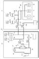
- FIG. 1 is an explanatory diagram showing an outline of the configuration of the blood processing system 1 according to the present embodiment.
- the blood processing system 1 is for performing, for example, a continuous gradual blood purification process.
- a blood processing apparatus 10 that performs blood processing on a patient, and a treatment liquid such as a dialysate or a replacement fluid is applied to the blood processing apparatus 10.
- a treatment liquid supply device 11 for supplying and replenishing and a control device 12 (including a drainage control device) are provided.
- the blood processing apparatus 10 has a blood processing circuit 21 that supplies the patient's blood to the blood purifier 20 and returns it to the patient.
- the blood processing circuit 21 has a blood supply circuit 22 for supplying the patient's blood to the blood purifier 20 and a blood return circuit 23 for returning the blood from the blood purifier 20 to the patient.
- the blood treatment apparatus 10 includes a treatment liquid supply circuit 24 that performs at least one of supply of a replacement fluid to the blood supply circuit 22 and / or the blood return circuit 23 and supply of dialysate to the blood purifier 20, blood A drain circuit 25 is provided for draining the waste liquid generated by the purifier 20.
- the blood purifier 20 is, for example, a hollow fiber module incorporating a hollow fiber membrane, and passes waste products or the like in the blood supplied to the primary side 20a of the hollow fiber membrane to the secondary side 20b of the hollow fiber membrane. Thus, blood can be filtered and purified.
- the blood supply circuit 22 is connected to the inlet of the primary side 20a of the blood purifier 20 from, for example, a needle portion (not shown) punctured by the patient.
- the blood supply circuit 22 is provided with a pump 30 and can supply the patient's blood to the blood purifier 20 at a predetermined flow rate.
- a so-called tube pump for handling a tube constituting a circuit and sending a liquid in the tube is used.
- the blood return circuit 23 is connected to the needle part (not shown) from the outlet of the primary side 20a of the blood purifier 20.
- the treatment liquid supply circuit 24 is connected from the first storage container 40 to either the blood supply circuit 22 and / or the blood return circuit 23 or the secondary side 20 b of the blood purifier 20.
- the treatment liquid supply circuit 24 is a type of blood purification treatment, such as continuous gradual hemofiltration (CHF), continuous dialysis hemodialysis (CHD), continuous dialysis hemodialysis (CHDF). According to continuous (HemoDiaFiltration), it can be selected whether to connect to the blood supply circuit 22 and / or the blood return circuit 23, to the blood purifier 20, or to a plurality of them.
- CHF continuous gradual hemofiltration
- CHD continuous dialysis hemodialysis
- CHDF continuous dialysis hemodialysis
- the treatment liquid supply circuit 24 is provided with a tube pump 41 as a supply pump, and can supply the dialysis liquid and the replacement liquid treatment liquid in the first storage container 40 at a predetermined flow rate.
- the first storage container 40 is provided with a first weighing scale 42 for measuring the weight of the container 40.
- the drain circuit 25 is connected to the drain container 50 from the secondary side 20b of the blood purifier 20.
- the drainage circuit 25 is provided with a tube pump 51 as a drainage pump, and the drainage of the blood purifier 20 can be discharged to the drainage container 50 at a predetermined flow rate.
- the drainage container 50 is provided with a third weigh scale 52 that measures the weight of the container 50.
- the therapeutic liquid supply apparatus 11 includes a therapeutic liquid generation unit 60 that generates a therapeutic liquid, a therapeutic liquid supply circuit 62 that supplies the therapeutic liquid generated by the therapeutic liquid generation unit 60 to the second storage container 61, a first A therapeutic liquid replenishment circuit 63 for replenishing the first storage container 40 of the blood processing apparatus 10 with the therapeutic liquid in the second storage container 61 is provided.
- the treatment liquid generation unit 60 has, for example, a water supply source 70, an A raw solution supply source 71, and a B raw solution supply source 72, and can mix these liquids at a predetermined ratio to generate a treatment liquid.
- a water supply source 70 for example, reverse osmosis filtered water, ultrafiltered water, or the like is used.
- a stock solution for example, a solution stock solution not containing sodium bicarbonate is used
- B stock solution for example, a solution stock solution containing sodium bicarbonate is used.
- the therapeutic liquid supply circuit 62 is connected from the therapeutic liquid generator 60 to the second storage container 61, and the therapeutic liquid replenishment circuit 63 is connected from the second storage container 61 to the therapeutic liquid supply circuit 24 of the blood processing apparatus 10. ing.
- the therapeutic liquid supply circuit 62 is provided with therapeutic liquid blocking means 64 such as an on-off valve or a tube pump.
- the treatment liquid replenishment circuit 63 is provided with a tube pump 80 and can supply the treatment liquid in the second storage container 61 to the treatment liquid supply circuit 24 at a predetermined flow rate.
- the second storage container 61 is provided with a second weigh scale 81 that measures the weight of the container 61.
- the control device 12 is a computer that controls the entire operation of the blood processing system 1, and controls the operations of the tube pumps 30, 41, 51, 80, the treatment liquid closing means 64, etc., to replenish the blood treatment and treatment liquid. Can be executed.
- the control device 12 has a program for correcting the flow rate error of the tube pump 41 based on the measurement results by the weight scales 42 and 81 and controlling the flow rate of the treatment liquid supplied to the blood processing circuit 21 as described later.
- the blood processing apparatus 10 and the treatment liquid supply apparatus 11 may each have a control computer, and the control apparatus 12 may control the whole by wired or wireless communication.
- a continuous gradual blood purification process is performed on a patient.
- CHF continuous gradual blood filtration
- the patient's blood is supplied to the blood purifier 20 through the blood supply circuit 22 by the tube pump 30. Waste products and the like removed from the blood through the membrane in the blood purifier 20 are discharged to the drainage container 50 through the drainage circuit 25 by the tube pump 51.
- the tube pump 41 supplies the replacement fluid in the first storage container 40 to the blood supply circuit 22 and / or the blood return circuit 23 through the treatment liquid supply circuit 24.
- the blood purified by the blood purifier 20 is returned to the patient through the blood return circuit 23.
- the dialysis fluid in the first storage container 40 is supplied to the secondary side 20 b of the membrane of the blood purifier 20 by the tube pump 41.
- CHDF continuous gradual hemodialysis
- the treatment liquid in the second storage container 61 is appropriately supplied to the first storage container 40 of the blood processing apparatus 10 and replenished. To do.
- the tube pump 80 supplies the treatment liquid supply circuit 24 of the blood processing apparatus 10 through the treatment liquid replenishment circuit 63.
- the therapeutic liquid supplied to the therapeutic liquid supply circuit 24 is mainly supplied to and stored in the first storage container 40, and in some cases, it is partially stored in at least one of the blood supply circuit 22, the blood return circuit 23, or the blood purifier 20. Supplied directly.
- the therapeutic liquid is generated by the therapeutic liquid generation unit 60 when the supply of the therapeutic liquid is stopped, and is stored in the second storage container 61 in advance.
- the treatment liquid supply blocking means 64 is closed, and the treatment liquid is not replenished to the second storage container 61.
- the therapeutic liquid supply means from the second storage container 61 to the first storage container 40 may be a liquid supply using a valve and a drop instead of the tube pump 80.
- the replenishment method using the head when the tube pump 41 operates at a high flow rate, the replenishment of the treatment liquid due to the head is not in time, and the treatment liquid in the first storage container 40 is quickly emptied, so that stable treatment is possible. The liquid cannot be supplied.
- it is preferable to use the tube pump 80 because the use of a head and a valve takes a place and the size of the entire blood processing system 1 cannot be increased.
- the control device 12 During the blood purification process, the control device 12 strictly controls the supply flow rate of the treatment liquid to the blood processing circuit 21. For example, during the blood purification process, the weight of the first storage container 40 is continuously measured by the first weighing scale 42, and the weight of the second storage container 61 is continuously measured by the second weighing scale 81. . These measurement results are output to the control device 12, and are supplied by the tube pump 41 from the change amount of the sum of the weight of the first storage container 40 and the weight of the second storage container 61. The actual flow rate Q1 of the treatment liquid is calculated.
- the control device 12 corrects a flow rate error p1 (Q2-Q1) between the actual flow rate Q1 of the tube pump 41 and a preset target flow rate Q2, for example, as shown in FIG.
- the flow rate error p1 is corrected by increasing the output of the tube pump 41 by the flow rate error.
- the control device 12 performs feedback control of the tube pump 41 continuously or intermittently, and strictly controls the flow rate of the treatment liquid supplied to the blood processing circuit 21.
- the control device 12 strictly controls the drainage flow rate from the blood purifier 20 of the blood processing circuit 21 to the drainage container 50.
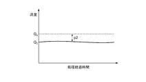
- the weight of the drainage container 50 is continuously measured by the third weighing scale 52 during the blood purification process. This measurement result is output to the control device 12, and the control device 12 calculates the actual flow rate Q3 of the drainage discharged by the tube pump 51 from the amount of change in the weight of the drainage container 50.
- the control device 12 corrects a flow rate error P2 (Q4-Q3) between the actual flow rate Q3 of the tube pump 51 and a preset target flow rate Q4 as shown in FIG. 3, for example.
- the flow rate error p2 is corrected by increasing the output of the tube pump 51 by the flow rate error.
- the control device 12 performs feedback control of the tube pump 51 continuously or intermittently, and strictly controls the flow rate of the drainage discharged from the blood purifier 20.
- the weight of the first storage container 40 and the weight of the second storage container 61 are measured, the actual flow rate Q1 of the tube pump 41 is calculated from the change amount ⁇ M of the sum, and the tube pump 41 is controlled to correct the flow rate error p1 between the actual flow rate Q1 and the target flow rate Q2, so that even if the first storage container 40 of the blood processing apparatus 10 is replenished with therapeutic liquid during blood processing, the treatment of the storage container
- the flow rate control of the tube pump 41 based on the decrease in the liquid can be performed. Therefore, the supply flow rate of the therapeutic liquid to the blood processing circuit 21 can be strictly controlled while replenishing the first storage container 40 of the blood processing apparatus 10 with the therapeutic liquid during blood processing.
- the blood processing system 1 further includes an external drain circuit 100 that discharges the drainage stored in the drainage container 50 to the outside, and appropriately drains during blood processing.
- the drainage of the container 50 may be discharged to the outside.
- the external drainage circuit 100 is connected from the drainage circuit 25 to the drainage unit 110 of the treatment liquid supply apparatus 11 and includes a tube pump 111.
- the tube pump 111 is activated, and the drainage of the drainage container 50 is drained through the external drainage circuit 100. To be discharged.
- the tube pump 51 of the drain circuit 25 continues to operate.
- the tube pump 111 is stopped and the drainage of the drainage is stopped.
- the flow control of the tube pump 51 of the drain circuit 25 is performed as follows. As described above, when the drainage of the drainage container 50 is not discharged through the external drainage circuit 100, the actual amount of the tube pump 51 is calculated from the amount of change in the weight of the drainage container 50 measured by the third weighing scale 52. The flow rate Q3 is calculated, and the tube pump 51 is controlled to correct the flow rate error p2 between the actual flow rate Q3 and the target flow rate Q4. Then, as shown in FIG. 5, while the drainage of the drainage container 50 is being discharged through the external drainage circuit 100, the tube is corrected using the correction value of the flow rate error p2 immediately before the discharge to the outside is started. The pump 51 is controlled.
- the correction value of the flow rate error p2 immediately before the drainage of the drainage container 50 is started is c1
- the correction value c1 of the flow rate error is maintained during drainage.
- the measurement of the weight of the drainage container 50 by the third weighing scale 52 is stopped.
- the measurement of the weight of the drainage container 50 by the third weighing scale 52 is started again, and the actual flow rate Q3 of the tube pump 51 is calculated based on the weight,
- the tube pump 51 is controlled to correct the flow rate error p2 between the actual flow rate Q3 and the target flow rate Q4.
- the blood processing can be continuously performed for a long period of time. Further, if the blood treatment is continued for a long time until the drainage container 50 has sufficiently accumulated the drainage, the actual flow rate Q3 of the tube pump 51 is stabilized, and the correction value c1 of the flow rate error p2 is stabilized.
- the tube pump 51 in the liquid is controlled using the correction value c1 of the flow rate error p2 immediately before the discharge of the drainage is started. By doing so, the drainage flow rate from the blood purifier 20 can be strictly controlled while draining the drainage during the blood treatment. Therefore, long-term blood treatment by the blood purifier 20 is appropriately performed.
- the blood processing system 1 includes a plurality of, for example, two second storage containers 61 as shown in FIG. 6, and the second storage containers 61A and 61B are provided with the second storage containers 61A and 61B.
- Weigh scales 81A and 81B are provided, and the first storage container 40 is replenished with the treatment liquid from one second storage container 61A and 61B sequentially selected from the plurality of second storage containers 61A and 61B. You may do it.
- the treatment liquid supply circuit 62 is branched in the middle so as to be connected to each of the second storage containers 61A and 61B.
- a three-way valve 120 is provided at this branch point.
- the treatment liquid replenishment circuit 63 is branched in the middle so as to be connected to each of the second storage containers 61A and 61B.
- a three-way valve 121 is provided at this branch point.
- the blood treatment it is selected from which second storage container 61A, 61B the first storage container 40 is replenished with the treatment liquid, and the unselected second storage containers 61A, 61B include The therapeutic liquid is replenished from the therapeutic liquid generation unit 60.
- the treatment liquid is replenished from the second storage container 61A to the first storage container 40 when the treatment liquid is replenished, and the second storage container 61B includes The therapeutic liquid is appropriately supplemented from the therapeutic liquid generation unit 60.
- the treatment liquid is replenished from the second storage container 61B to the first storage container 40 when the treatment liquid is replenished, and the second storage container 61A
- the therapeutic liquid is appropriately supplemented from the therapeutic liquid generation unit 60.
- the selection of the second storage container 61A and the second storage container 61B is performed alternately.
- the flow rate control of the tube pump 41 of the treatment liquid supply circuit 24 is performed by adding the weight of the second storage container 61 to which the first storage container 40 is replenished (selected) and the first storage container 40.
- the actual flow rate Q1 of the tube pump 41 is calculated from the amount of change in the total with the weight of the storage container 40, and the tube pump 41 is controlled to correct the flow rate error p1 between the actual flow rate Q1 and the target flow rate Q2.
- the blood processing system 1 has a plurality of second storage containers 61, replenishment of the treatment liquid to the first storage container 40, and the supply of the treatment liquid to the second storage container 61. Since the replenishment can be performed alternately, the flow rate of the tube pump 80 only needs to be equal to or higher than the flow rate required for the tube pump 41, so that the pump can be downsized. In addition, it is possible to strictly control the supply flow rate of the treatment liquid of the tube pump 41 at that time. In addition, the number of the 2nd storage containers 61 in this Embodiment is not restricted to two, It can select arbitrarily.
- the blood processing system 1 includes the blood processing apparatus 10 and the treatment liquid supply apparatus 11, but they may be independent or integrated.
- the treatment liquid supply is not performed from the treatment liquid supply apparatus 11 but by connecting an existing prepared treatment liquid bag instead of the first storage container 40, thereby supplying the treatment liquid supply apparatus. Treatment may be performed without using 11. Therefore, in order to give flexibility to the embodiment of treatment, the first storage container 40 is installed on the blood processing apparatus 10 side, the second storage container 61 is installed on the treatment liquid supply apparatus 11 side, and the blood processing apparatus 10
- the treatment liquid supply device 11 is preferably configured independently.
- the blood processing apparatus 10 already exists in the market, and a large investment is required when developing in an integrated type. Therefore, by designing the blood processing apparatus 10 and the treatment liquid supply apparatus 11 as independent devices, development costs can be suppressed and smooth introduction into the existing market becomes possible.
- the respective circuits are connected to each other through the treatment liquid replenishment circuit 63 and the treatment liquid supply circuit 24.
- a luer connector or the like can be used for connection, but there is no particular limitation as long as each circuit can be connected.
- the treatment liquid replenishment circuit 63 and the treatment liquid supply circuit 24 can be directly connected or connected via the first storage container 40, but the treatment liquid is connected to the first storage container 40. There is no particular limitation as long as it can be supplied.
- the treatment liquid replenishment circuit 63 when the treatment liquid replenishment circuit 63 is not connected in advance to the connection portion with respect to the treatment liquid supply circuit 24, a clamp, a check valve, a needleless mixed injection tube, or the like may be arranged at the connection portion to prevent leakage of the treatment liquid. .
- the blood processing apparatus 10 and the treatment liquid supply apparatus 11 are configured independently, it is necessary to control the measurement results of the first weight scale 41 and the second weight scale 81 by sharing each other. There is. For this purpose, it is necessary that the blood processing apparatus 10 and the treatment liquid supply apparatus 11 are electrically linked.
- the means may be a physical connection such as an RS232 cable, an RS422 cable, a LAN cable, or a USB cable, or Blue.
- a wireless signal such as a tooth (registered trademark) or an infrared ray can be used, but any signal can be used as long as it can transmit information necessary for control, and the signal is not particularly limited.
- the second storage container 61 is on the treatment liquid supply device 11 side, but is not particularly limited to this, and may be on the blood processing device 10 side.
- the circuit configuration of the blood processing system 1 is not limited to this.
- the pumps 41 and 51 to be controlled may not be tube pumps.
- the flow rate control of the tube pump 41 of the treatment liquid supply circuit 24 is performed and the flow rate control of the tube pump 51 of the drainage circuit 25 is performed.
- Good That is, while the drainage of the drainage container 50 is not discharged to the outside through the external drainage circuit 100, the actual flow rate of the tube pump 51 is calculated from the amount of change in the weight of the drainage container 50 measured by the weigh scale 52. Q3 is calculated, the tube pump 51 is controlled to correct the flow rate error p2 between the actual flow rate Q3 and the target flow rate Q4, and while the drainage of the drainage container 50 is being discharged to the outside through the external drainage circuit 100.
- the tube pump 51 may be controlled using the correction value c1 of the flow rate error p2 immediately before the discharge of the drainage is started.
- the blood processing system of the present invention can also be applied to the case where a therapeutic liquid is supplied to a blood processing apparatus other than the sustained release type.
- the present invention is useful in providing a blood processing system that strictly controls the supply flow rate of the therapeutic liquid to the blood processing circuit while replenishing the therapeutic liquid in the storage container of the blood processing apparatus during blood processing.
Landscapes
- Health & Medical Sciences (AREA)
- Heart & Thoracic Surgery (AREA)
- Vascular Medicine (AREA)
- Life Sciences & Earth Sciences (AREA)
- Engineering & Computer Science (AREA)
- Anesthesiology (AREA)
- Biomedical Technology (AREA)
- Hematology (AREA)
- Animal Behavior & Ethology (AREA)
- General Health & Medical Sciences (AREA)
- Public Health (AREA)
- Veterinary Medicine (AREA)
- Cardiology (AREA)
- Emergency Medicine (AREA)
- Urology & Nephrology (AREA)
- External Artificial Organs (AREA)
Abstract
La présente invention concerne un système (1) de traitement du sang comprenant : un circuit (21) de traitement du sang qui alimente un épurateur (20) de sang en un sang de patient et renvoie le sang au patient; un circuit (24) d'alimentation en liquide thérapeutique qui alimente le circuit (21) de traitement du sang en liquide thérapeutique qui est un liquide de dialyse ou un liquide de remplissage stocké dans un premier récipient de stockage (40) à l'aide d'une pompe à tube (41); un circuit (63) de recharge en liquide thérapeutique qui recharge le premier récipient de stockage (40) en liquide thérapeutique stocké dans un second récipient de stockage (61); un premier plateau (42) de balance; un second plateau (81) de balance; et un dispositif de commande (12) qui calcule le débit réel de la pompe à tube (41) à partir de la quantité de variation de la somme du poids du premier récipient de stockage (40) tel que mesuré par le premier plateau (42) de balance et du poids du second récipient de stockage (61) tel que mesuré par le second plateau (81) de balance, et qui corrige une erreur de débit entre le débit réel et un débit cible par la commande de la pompe à tube (41).
Priority Applications (4)
| Application Number | Priority Date | Filing Date | Title |
|---|---|---|---|
| CN201580070193.0A CN107106755B (zh) | 2014-12-25 | 2015-12-25 | 血液处理系统 |
| JP2016566524A JPWO2016104720A1 (ja) | 2014-12-25 | 2015-12-25 | 血液処理システム |
| EP15873288.3A EP3238761B1 (fr) | 2014-12-25 | 2015-12-25 | Système de traitement du sang |
| EP19161541.8A EP3524289B1 (fr) | 2014-12-25 | 2015-12-25 | Système de traitement du sang |
Applications Claiming Priority (2)
| Application Number | Priority Date | Filing Date | Title |
|---|---|---|---|
| JP2014262923 | 2014-12-25 | ||
| JP2014-262923 | 2014-12-25 |
Publications (1)
| Publication Number | Publication Date |
|---|---|
| WO2016104720A1 true WO2016104720A1 (fr) | 2016-06-30 |
Family
ID=56150732
Family Applications (1)
| Application Number | Title | Priority Date | Filing Date |
|---|---|---|---|
| PCT/JP2015/086265 WO2016104720A1 (fr) | 2014-12-25 | 2015-12-25 | Système de traitement du sang |
Country Status (4)
| Country | Link |
|---|---|
| EP (2) | EP3524289B1 (fr) |
| JP (3) | JPWO2016104720A1 (fr) |
| CN (1) | CN107106755B (fr) |
| WO (1) | WO2016104720A1 (fr) |
Cited By (7)
| Publication number | Priority date | Publication date | Assignee | Title |
|---|---|---|---|---|
| JP2020000803A (ja) * | 2018-07-02 | 2020-01-09 | ニプロ株式会社 | 血液浄化装置 |
| WO2020096018A1 (fr) * | 2018-11-08 | 2020-05-14 | 日機装株式会社 | Dispositif de purification du sang |
| WO2020096017A1 (fr) * | 2018-11-08 | 2020-05-14 | 日機装株式会社 | Dispositif d'épuration de sang |
| CN111526900A (zh) * | 2017-10-31 | 2020-08-11 | 耐斯特基尼公司 | 自动体外血液处理装置 |
| JP2020151191A (ja) * | 2019-03-20 | 2020-09-24 | 日機装株式会社 | 血液浄化装置 |
| EP3797803A1 (fr) | 2019-09-26 | 2021-03-31 | B. Braun Avitum AG | Dispositif de traitement du sang avec surveillance améliorée du poids des sacs |
| WO2024150754A1 (fr) * | 2023-01-12 | 2024-07-18 | ニプロ株式会社 | Dispositif de purification du sang |
Families Citing this family (7)
| Publication number | Priority date | Publication date | Assignee | Title |
|---|---|---|---|---|
| CN107485742A (zh) * | 2017-09-08 | 2017-12-19 | 重庆山外山血液净化技术股份有限公司 | 血液净化系统及该血液净化系统的管路预充控制方法 |
| CN107412895B (zh) * | 2017-09-08 | 2021-03-02 | 重庆山外山血液净化技术股份有限公司 | 血液净化称重补偿方法及利用该方法的血液净化称重补偿系统 |
| WO2020137190A1 (fr) * | 2018-12-28 | 2020-07-02 | 日機装株式会社 | Dispositif de purification du sang |
| CN117897183A (zh) * | 2021-08-09 | 2024-04-16 | 甘布罗伦迪亚股份公司 | 生成用于肾脏替代疗法的医疗流体 |
| CN117813122A (zh) * | 2021-08-09 | 2024-04-02 | 甘布罗伦迪亚股份公司 | 用于供应用于肾脏替代治疗的医用流体的系统和操作这种系统的方法 |
| CN118401264A (zh) | 2021-12-15 | 2024-07-26 | 巴克斯特国际公司 | 用于体外血液处理中使用的基于重量的系统 |
| WO2023174604A1 (fr) * | 2022-03-16 | 2023-09-21 | Gambro Lundia Ab | Génération de fluide médical pour thérapie de remplacement rénal |
Citations (5)
| Publication number | Priority date | Publication date | Assignee | Title |
|---|---|---|---|---|
| JPH09239024A (ja) * | 1996-03-01 | 1997-09-16 | Asahi Medical Co Ltd | 血液浄化装置 |
| JP2006095184A (ja) * | 2004-09-30 | 2006-04-13 | Asahi Kasei Medical Co Ltd | 血液浄化装置 |
| JP4458346B2 (ja) * | 2004-07-12 | 2010-04-28 | 旭化成クラレメディカル株式会社 | 持続緩徐式血液ろ過透析装置 |
| JP2012200275A (ja) * | 2011-03-23 | 2012-10-22 | Asahi Kasei Medical Co Ltd | 血液浄化システム |
| JP2014513990A (ja) * | 2011-02-01 | 2014-06-19 | フレセニウス メディカル ケア ドイチュランド ゲーエムベーハー | 体外血液処理装置の制御方法及び制御装置 |
Family Cites Families (12)
| Publication number | Priority date | Publication date | Assignee | Title |
|---|---|---|---|---|
| US5215519A (en) * | 1990-03-07 | 1993-06-01 | Shettigar U Ramakrishna | Autotransfusion membrane system with means for providing reverse filtration |
| US5378227A (en) * | 1992-08-11 | 1995-01-03 | Cobe Laboratories, Inc. | Biological/pharmaceutical method and apparatus for collecting and mixing fluids |
| IT1285624B1 (it) * | 1996-03-18 | 1998-06-18 | Bellco Spa | Apparecchiatura per trattamenti di dialisi |
| CA2495561C (fr) * | 2002-08-08 | 2008-11-18 | Asahi Kasei Medical Co., Ltd. | Dispositif de purification de sang et procede d'utilisation correspondant |
| US7686778B2 (en) * | 2003-01-15 | 2010-03-30 | Nxstage Medical, Inc. | Waste balancing for extracorporeal blood treatment systems |
| CN101378797B (zh) * | 2006-02-07 | 2013-08-07 | 株式会社Jms | 血液净化装置以及血液净化回路 |
| US8496809B2 (en) * | 2006-06-05 | 2013-07-30 | Baxter International Inc. | Dynamic weight balancing of flow in kidney failure treatment systems |
| US8202241B2 (en) * | 2007-02-15 | 2012-06-19 | Asahi Kasei Medical Co., Ltd. | Blood purification system |
| CN202497518U (zh) * | 2012-03-16 | 2012-10-24 | 重庆山外山科技有限公司 | 连续性血液净化治疗装置 |
| US10328193B2 (en) * | 2012-03-21 | 2019-06-25 | Gambro Lundia Ab | Extracorporeal blood treatment apparatus with multiple treatment solution reservoirs |
| EP2641624B1 (fr) * | 2012-03-21 | 2016-03-02 | Gambro Lundia AB | Administration de solution de traitement dans un appareil de traitement sanguin extracorporel |
| US9579443B2 (en) * | 2013-01-10 | 2017-02-28 | Fresenius Medical Care Holdings, Inc. | Peritoneal dialysis systems and related devices and methods |
-
2015
- 2015-12-25 EP EP19161541.8A patent/EP3524289B1/fr active Active
- 2015-12-25 WO PCT/JP2015/086265 patent/WO2016104720A1/fr active Application Filing
- 2015-12-25 JP JP2016566524A patent/JPWO2016104720A1/ja active Pending
- 2015-12-25 EP EP15873288.3A patent/EP3238761B1/fr active Active
- 2015-12-25 CN CN201580070193.0A patent/CN107106755B/zh active Active
-
2019
- 2019-03-04 JP JP2019038932A patent/JP6705035B2/ja active Active
- 2019-03-04 JP JP2019038931A patent/JP6782317B2/ja active Active
Patent Citations (5)
| Publication number | Priority date | Publication date | Assignee | Title |
|---|---|---|---|---|
| JPH09239024A (ja) * | 1996-03-01 | 1997-09-16 | Asahi Medical Co Ltd | 血液浄化装置 |
| JP4458346B2 (ja) * | 2004-07-12 | 2010-04-28 | 旭化成クラレメディカル株式会社 | 持続緩徐式血液ろ過透析装置 |
| JP2006095184A (ja) * | 2004-09-30 | 2006-04-13 | Asahi Kasei Medical Co Ltd | 血液浄化装置 |
| JP2014513990A (ja) * | 2011-02-01 | 2014-06-19 | フレセニウス メディカル ケア ドイチュランド ゲーエムベーハー | 体外血液処理装置の制御方法及び制御装置 |
| JP2012200275A (ja) * | 2011-03-23 | 2012-10-22 | Asahi Kasei Medical Co Ltd | 血液浄化システム |
Non-Patent Citations (1)
| Title |
|---|
| See also references of EP3238761A4 * |
Cited By (18)
| Publication number | Priority date | Publication date | Assignee | Title |
|---|---|---|---|---|
| CN111526900A (zh) * | 2017-10-31 | 2020-08-11 | 耐斯特基尼公司 | 自动体外血液处理装置 |
| US11975133B2 (en) | 2017-10-31 | 2024-05-07 | Nextkidney Sa | Easily movable blood purification systems |
| CN111526900B (zh) * | 2017-10-31 | 2023-09-05 | 耐斯特基尼公司 | 自动体外血液处理装置 |
| JP7110766B2 (ja) | 2018-07-02 | 2022-08-02 | ニプロ株式会社 | 血液浄化装置 |
| JP2020000803A (ja) * | 2018-07-02 | 2020-01-09 | ニプロ株式会社 | 血液浄化装置 |
| JP2020074988A (ja) * | 2018-11-08 | 2020-05-21 | 日機装株式会社 | 血液浄化装置 |
| JP2020074987A (ja) * | 2018-11-08 | 2020-05-21 | 日機装株式会社 | 血液浄化装置 |
| JP7189736B2 (ja) | 2018-11-08 | 2022-12-14 | 日機装株式会社 | 血液浄化装置 |
| JP7262207B2 (ja) | 2018-11-08 | 2023-04-21 | 日機装株式会社 | 血液浄化装置 |
| WO2020096017A1 (fr) * | 2018-11-08 | 2020-05-14 | 日機装株式会社 | Dispositif d'épuration de sang |
| US11911544B2 (en) | 2018-11-08 | 2024-02-27 | Nikkiso Company Limited | Blood purification apparatus |
| US11951245B2 (en) | 2018-11-08 | 2024-04-09 | Nikkiso Company Limited | Blood purification apparatus |
| WO2020096018A1 (fr) * | 2018-11-08 | 2020-05-14 | 日機装株式会社 | Dispositif de purification du sang |
| JP2020151191A (ja) * | 2019-03-20 | 2020-09-24 | 日機装株式会社 | 血液浄化装置 |
| JP7224219B2 (ja) | 2019-03-20 | 2023-02-17 | 日機装株式会社 | 血液浄化装置 |
| EP3797803A1 (fr) | 2019-09-26 | 2021-03-31 | B. Braun Avitum AG | Dispositif de traitement du sang avec surveillance améliorée du poids des sacs |
| US11524101B2 (en) | 2019-09-26 | 2022-12-13 | B. Braun Avitum Ag | Blood treatment device with improved bag weight monitoring |
| WO2024150754A1 (fr) * | 2023-01-12 | 2024-07-18 | ニプロ株式会社 | Dispositif de purification du sang |
Also Published As
| Publication number | Publication date |
|---|---|
| CN107106755A (zh) | 2017-08-29 |
| EP3238761A1 (fr) | 2017-11-01 |
| JPWO2016104720A1 (ja) | 2017-10-19 |
| JP6705035B2 (ja) | 2020-06-03 |
| CN107106755B (zh) | 2019-07-16 |
| JP6782317B2 (ja) | 2020-11-11 |
| JP2019107500A (ja) | 2019-07-04 |
| EP3524289B1 (fr) | 2021-03-10 |
| JP2019115694A (ja) | 2019-07-18 |
| EP3238761A4 (fr) | 2018-06-06 |
| EP3524289A1 (fr) | 2019-08-14 |
| EP3238761B1 (fr) | 2019-06-19 |
Similar Documents
| Publication | Publication Date | Title |
|---|---|---|
| JP6705035B2 (ja) | 血液処理システム | |
| US11400426B2 (en) | System and method for preparation of a medical fluid | |
| CN107427620B (zh) | 透析液供给系统 | |
| JP6286073B2 (ja) | 治療液作成装置及び血液処理システム | |
| CN112312938A (zh) | 透析期间的耗尽时间的计算 | |
| JP6335333B2 (ja) | 溶液生成装置及び血液浄化システム | |
| US20220126007A1 (en) | Pump calibration during bag filling | |
| US20220305179A1 (en) | Medicament Preparation Devices, Methods, and Systems | |
| JP7274196B2 (ja) | 制御装置、透析システム、制御プログラム、および記録媒体 | |
| US20220296796A1 (en) | Medicament Preparation Devices, Methods, and Systems | |
| US20220305180A1 (en) | Medicament Preparation Devices, Methods, and Systems | |
| JP6512805B2 (ja) | 血液浄化システム | |
| JP2016106906A (ja) | 血液浄化システム |
Legal Events
| Date | Code | Title | Description |
|---|---|---|---|
| 121 | Ep: the epo has been informed by wipo that ep was designated in this application |
Ref document number: 15873288 Country of ref document: EP Kind code of ref document: A1 |
|
| ENP | Entry into the national phase |
Ref document number: 2016566524 Country of ref document: JP Kind code of ref document: A |
|
| REEP | Request for entry into the european phase |
Ref document number: 2015873288 Country of ref document: EP |
|
| NENP | Non-entry into the national phase |
Ref country code: DE |