WO2016104242A1 - 多芯ケーブルのシール構造、及び、シール部材 - Google Patents
多芯ケーブルのシール構造、及び、シール部材 Download PDFInfo
- Publication number
- WO2016104242A1 WO2016104242A1 PCT/JP2015/085027 JP2015085027W WO2016104242A1 WO 2016104242 A1 WO2016104242 A1 WO 2016104242A1 JP 2015085027 W JP2015085027 W JP 2015085027W WO 2016104242 A1 WO2016104242 A1 WO 2016104242A1
- Authority
- WO
- WIPO (PCT)
- Prior art keywords
- sheath
- cap
- electric wire
- rubber plug
- locking
- Prior art date
Links
- 238000002788 crimping Methods 0.000 claims abstract description 27
- 238000007789 sealing Methods 0.000 claims description 28
- 238000003825 pressing Methods 0.000 abstract description 2
- 230000035515 penetration Effects 0.000 description 15
- 238000005192 partition Methods 0.000 description 6
- 238000005516 engineering process Methods 0.000 description 5
- 238000003780 insertion Methods 0.000 description 5
- 230000037431 insertion Effects 0.000 description 5
- 239000002184 metal Substances 0.000 description 4
- 230000002093 peripheral effect Effects 0.000 description 4
- 230000000694 effects Effects 0.000 description 3
- 238000004519 manufacturing process Methods 0.000 description 3
- 238000000034 method Methods 0.000 description 3
- 230000000149 penetrating effect Effects 0.000 description 3
- 229920003002 synthetic resin Polymers 0.000 description 3
- 239000000057 synthetic resin Substances 0.000 description 3
- 230000000994 depressogenic effect Effects 0.000 description 2
- 239000007788 liquid Substances 0.000 description 2
- XLYOFNOQVPJJNP-UHFFFAOYSA-N water Substances O XLYOFNOQVPJJNP-UHFFFAOYSA-N 0.000 description 2
- 229910001111 Fine metal Inorganic materials 0.000 description 1
- 238000005452 bending Methods 0.000 description 1
- 238000005266 casting Methods 0.000 description 1
- 239000011248 coating agent Substances 0.000 description 1
- 238000000576 coating method Methods 0.000 description 1
- 230000002708 enhancing effect Effects 0.000 description 1
- 238000009413 insulation Methods 0.000 description 1
- 238000012423 maintenance Methods 0.000 description 1
- 239000003921 oil Substances 0.000 description 1
- 239000003960 organic solvent Substances 0.000 description 1
- 229920005989 resin Polymers 0.000 description 1
- 239000011347 resin Substances 0.000 description 1
- 238000004078 waterproofing Methods 0.000 description 1
Images


Classifications
-
- H—ELECTRICITY
- H02—GENERATION; CONVERSION OR DISTRIBUTION OF ELECTRIC POWER
- H02G—INSTALLATION OF ELECTRIC CABLES OR LINES, OR OF COMBINED OPTICAL AND ELECTRIC CABLES OR LINES
- H02G15/00—Cable fittings
- H02G15/02—Cable terminations
- H02G15/04—Cable-end sealings
- H02G15/043—Cable-end sealings with end caps, e.g. sleeve closed at one end
-
- H—ELECTRICITY
- H01—ELECTRIC ELEMENTS
- H01B—CABLES; CONDUCTORS; INSULATORS; SELECTION OF MATERIALS FOR THEIR CONDUCTIVE, INSULATING OR DIELECTRIC PROPERTIES
- H01B7/00—Insulated conductors or cables characterised by their form
- H01B7/17—Protection against damage caused by external factors, e.g. sheaths or armouring
- H01B7/18—Protection against damage caused by wear, mechanical force or pressure; Sheaths; Armouring
-
- H—ELECTRICITY
- H01—ELECTRIC ELEMENTS
- H01B—CABLES; CONDUCTORS; INSULATORS; SELECTION OF MATERIALS FOR THEIR CONDUCTIVE, INSULATING OR DIELECTRIC PROPERTIES
- H01B7/00—Insulated conductors or cables characterised by their form
- H01B7/17—Protection against damage caused by external factors, e.g. sheaths or armouring
- H01B7/28—Protection against damage caused by moisture, corrosion, chemical attack or weather
-
- H—ELECTRICITY
- H02—GENERATION; CONVERSION OR DISTRIBUTION OF ELECTRIC POWER
- H02G—INSTALLATION OF ELECTRIC CABLES OR LINES, OR OF COMBINED OPTICAL AND ELECTRIC CABLES OR LINES
- H02G15/00—Cable fittings
- H02G15/013—Sealing means for cable inlets
-
- H—ELECTRICITY
- H01—ELECTRIC ELEMENTS
- H01B—CABLES; CONDUCTORS; INSULATORS; SELECTION OF MATERIALS FOR THEIR CONDUCTIVE, INSULATING OR DIELECTRIC PROPERTIES
- H01B7/00—Insulated conductors or cables characterised by their form
- H01B7/0009—Details relating to the conductive cores
-
- H—ELECTRICITY
- H02—GENERATION; CONVERSION OR DISTRIBUTION OF ELECTRIC POWER
- H02G—INSTALLATION OF ELECTRIC CABLES OR LINES, OR OF COMBINED OPTICAL AND ELECTRIC CABLES OR LINES
- H02G15/00—Cable fittings
- H02G15/02—Cable terminations
- H02G15/04—Cable-end sealings
- H02G15/043—Cable-end sealings with end caps, e.g. sleeve closed at one end
- H02G15/046—Cable-end sealings with end caps, e.g. sleeve closed at one end with bores or protruding portions allowing passage of cable conductors
-
- H—ELECTRICITY
- H02—GENERATION; CONVERSION OR DISTRIBUTION OF ELECTRIC POWER
- H02G—INSTALLATION OF ELECTRIC CABLES OR LINES, OR OF COMBINED OPTICAL AND ELECTRIC CABLES OR LINES
- H02G3/00—Installations of electric cables or lines or protective tubing therefor in or on buildings, equivalent structures or vehicles
- H02G3/22—Installations of cables or lines through walls, floors or ceilings, e.g. into buildings
Definitions
- the technology disclosed in this specification relates to a multi-core cable seal structure and a seal member.
- a rubber plug having a plurality of electric wire insertion holes through which the plurality of electric wires are inserted is known.
- each electric wire and the rubber plug are sealed.
- the technology disclosed in the present specification has been completed based on the above circumstances, and a sealing structure for a multi-core cable capable of enhancing the sealing performance between an electric wire and a rubber plug, and a sealing member
- the purpose is to provide.
- the multi-core cable sealing structure disclosed in this specification includes a multi-core cable in which a plurality of electric wires are surrounded by a sheath and the plurality of electric wires are led out from an end of the sheath, and each of the plurality of electric wires.
- a rubber plug that is inserted through the end of the sheath and is fitted over the rubber plug and presses the rubber plug inward, and the sheath is arranged alongside the rubber plug
- a caulking member that is caulked to the cap, wherein the caulking member has a locking portion and the cap has a locked portion, and the locking portion and the locked portion are locked.
- the sealing member disclosed in the present specification is attached to a multi-core cable in which a plurality of electric wires are surrounded by a sheath and the plurality of electric wires are led out from an end portion of the sheath. And a rubber plug that is fitted around the end of the sheath, a cap that is fitted around the rubber plug and presses the rubber plug inward, and the rubber plug. And a caulking member that is caulked to the sheath, the caulking member has a locking portion, the cap has a locked portion, and the locking portion and the locked portion are By locking, the relative positions of the caulking member and the cap are maintained.
- the cap is fitted on the rubber plug and presses the rubber plug inward, so that the cap and the rubber plug are held in a relative position.
- the crimping member crimps the sheath, the relative position between the crimping member and the sheath is maintained. Further, in the portion of the sheath that is crimped by the crimping member, the plurality of electric wires are held by the crimping member so as not to move within the sheath.
- the sealing structure of the multi-core cable and the sealing member may have the following configuration.
- the caulking member includes a main body portion for caulking the sheath, the locking portion is a locking piece extending from the main body portion toward the cap, and the locked portion is a receiving concave portion into which the locking piece is fitted.
- the caulking member and the cap are prevented from rotating by locking the locking piece and the receiving recess.
- the main body portion can be attached to the sheath with a simple configuration and with the engaging piece of the caulking member fitted into the receiving recess of the cap while performing easy alignment. Moreover, since the caulking member and the cap are prevented from rotating, the electric wire is prevented from being twisted with respect to the rubber plug.
- the caulking member may be configured to have a main body portion that caulks the sheath by forming a cylindrical shape having a C-shaped cross section along the outer periphery of the sheath.
- the caulking member may be provided with a main body portion that is crimped so as to be wound around the outer periphery of the sheath and caulking the sheath.
- the sealing performance between a plurality of electric wires led out from a multicore cable and a rubber plug can be improved.
- top view which shows the sealing structure and sealing member of the multi-core cable which concern on one Embodiment
- Bottom view showing the sealing structure and sealing member of a multi-core cable III-III sectional view in FIG. IV-IV sectional view in FIG.
- Front view showing seal member Sectional view taken along line VI-VI in FIG. Sectional view taken along line VII-VII in FIG.
- FIG. 1 Perspective view showing rubber stopper Top view showing rubber stopper Front view showing rubber stopper Rear view showing rubber stopper Perspective view showing a cap Rear view showing cap
- FIG. 1 Perspective view showing rubber stopper Top view showing rubber stopper Front view showing rubber stopper Rear view showing rubber stopper Perspective view showing a cap Rear view showing cap
- FIG. 1 Perspective view showing rubber stopper Top view showing rubber stopper Front view showing rubber stopper Rear view showing rubber stopper Perspective view showing a cap Rear view showing cap
- FIG. 1 Perspective view showing rubber stopper Top view showing rubber stopper Front view showing rubber stopper Rear view showing rubber stopper Perspective view showing a cap Rear view showing cap
- FIG. 1 Perspective view showing rubber stopper Top view showing rubber stopper Front view showing rubber stopper Rear view showing rubber stopper Perspective view showing a cap Rear view showing cap
- FIG. 1 Perspective view showing rubber stopper Top view showing rubber stopper Front view showing rubber stopper Rear view showing rubber stopper Perspective view showing a cap Rear view showing cap
- FIG. 1 Perspective view showing rubber stop
- FIGS. 1 to 26 One embodiment will be described with reference to FIGS. 1 to 26.
- the present embodiment can be used, for example, for a wire harness for an electric parking brake mounted on a vehicle (not shown).
- the right side in FIG. 1 is the front and the left side is the rear.
- the upper side in FIG. 3 is the upper side, and the lower side is the lower side.
- symbol may be attached
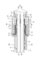
- the multi-core cable 11 As shown in FIG. 3 to FIG. 4 and FIG. 16 to FIG. 18, the multi-core cable 11 according to the present embodiment has a plurality of electric wires 13A, 13B, 13C, and 13D (four in the present embodiment) combined with insulation.
- the structure is surrounded by a resin sheath 14.
- the electric wires 13A, 13B, 13C, and 13D have a configuration in which the outer periphery of a metal core wire (not shown) is covered with a synthetic resin insulating coating (not shown).
- the cross-sectional shape of the multicore cable 11 is circular.
- the electric wires 13A, 13B, 13C, and 13D are referred to as the electric wires 13 when described without distinction.
- the four electric wires 13A, 13B, 13C, and 13D include two types of electric wires 13A, 13B, 13C, and 13D having different outer diameter dimensions.
- a first electric wire 13A and a second electric wire 13B connected to a motor for an electric parking brake, a third electric wire 13C for an anti-lock brake system sensor, and a fourth electric wire 13D are included.
- the cross-sectional shapes of the first electric wire 13A, the second electric wire 13B, the third electric wire 13C, and the fourth electric wire 13D are circular.
- the outer diameter of the first electric wire 13A and the second electric wire 13B is set larger than the outer diameter of the third electric wire 13C and the fourth electric wire 13D.
- the outer diameter of the first electric wire 13A and the outer diameter of the second electric wire 13B are set to be the same.
- the outer diameter dimension of the third electric wire 13C and the outer diameter dimension of the fourth electric wire 13D are set to be the same.
- a first electric wire 13A, a second electric wire 13B, a third electric wire 13C, and a fourth electric wire 13D are led out from the end portion 14A of the sheath 14 of the multicore cable 11 and branched.
- seal member 10 As shown in FIGS. 1 to 4, in the end portion 14A of the sheath 14 of the multi-core cable 11, there is a region where the first electric wire 13A, the second electric wire 13B, the third electric wire 13C, and the fourth electric wire 13D are branched.
- a seal member 10 is attached.
- the seal member 10 prevents liquid such as water and oil from entering the sheath 14 from the end portion 14A of the sheath 14.
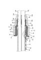
- the seal member 10 includes a rubber plug 15 attached to the end portion 14A of the sheath 14, a guide member 16 attached to the inside of the rubber plug 15, a cap 17 fitted to the rubber plug 15, and a portion close to the end portion of the sheath 14. , And a caulking member 40 that is externally fitted along with the rubber plug 15.
- a rubber plug 15 is attached to the end portion 14 ⁇ / b> A of the sheath 14.
- the rubber plug 15 has a sheath outer fitting portion 18 that is fitted on the end portion 14 ⁇ / b> A of the sheath 14.
- the sheath outer fitting portion 18 is formed in a hood shape that opens toward the rear side (left side in FIG. 3).
- the sheath outer fitting portion 18 is formed in a substantially cylindrical shape in a natural state.
- a flange portion 19 protruding outward in the radial direction of the sheath outer fitting portion 18 is formed at the rear edge of the sheath outer fitting portion 18 (see FIGS. 8 and 9).
- a part of the flange portion 19 is provided with a cutout portion 19A for passing an extension piece 17A of the cap 17 described later (see FIGS. 10 and 11).
- a plurality of sheath side lips 20 projecting inward are annularly provided along the circumferential direction of the sheath outer fitting portion 18 on the inner circumference of the sheath outer fitting portion 18. Is formed.
- the sheath side lip 20 is in close contact with the outer periphery of the sheath 14 in a state where the sheath outer fitting portion 18 is fitted on the end portion 14 ⁇ / b> A of the sheath 14. Thereby, the gap between the rubber plug 15 and the sheath 14 is sealed.
- the first electric wire 13 ⁇ / b> A, the second electric wire 13 ⁇ / b> B, the third electric wire 13 ⁇ / b> C, and the fourth electric wire are disposed at the front end (right side in FIG. 3) of the rubber plug 15.
- An electric wire penetrating portion 21 having a plurality of (four in this embodiment) through holes 22A, 22B, 22C, and 22D through which each of the electric wires 13D passes is provided.
- the plurality of through holes 22A, 22B, 22C, and 22D are penetrated by the first through hole 22A through which the first electric wire 13A passes, the second through hole 22B through which the second electric wire 13B passes, and the third electric wire 13C.
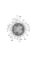
- the cross-sectional shape of the wire penetration portion 21 is formed in a trapezoidal shape with rounded corners.
- the cross-sectional shape of the wire penetrating portion 21 includes a long side 23 extending in the vertical direction, a short side 24 parallel to the long side 23 and shorter than the long side 23, an end of the long side 23, and an end of the short side 24. And two hypotenuses 25 connecting the sections.
- a first through hole 22A and a second through hole 22B are formed side by side along the direction in which the long side 23 extends (vertical direction) at a position near the long side 23. Further, in the wire penetration part 21, a third through hole 22 ⁇ / b> C and a fourth through hole 22 ⁇ / b> D are formed side by side along the direction (vertical direction) in which the short side 24 extends at a position near the short side 24.
- the inner diameter of the first through hole 22A is slightly larger than the outer diameter of the first electric wire 13A.
- a first electric wire side lip 26A (an example of an electric wire side lip) that is in close contact with the outer periphery of the first electric wire 13A is provided in the first through hole 22A. It is formed in an annular shape along the circumferential direction.
- the first electric wire side lip 26A is in close contact with the outer periphery of the first electric wire 13A in a state where the first electric wire 13A is penetrated into the first through hole 22A. Thereby, the space between the first electric wire 13A and the rubber plug 15 is sealed.
- the inner diameter dimension of the second through hole 22B is slightly larger than the outer diameter dimension of the second electric wire 13B.
- a second electric wire side lip 26B (an example of an electric wire side lip) that is in close contact with the outer periphery of the second electric wire 13B is provided in the second through hole 22B. It is formed in an annular shape along the circumferential direction.
- the 2nd electric wire side lip 26B is closely_contact
- the inner diameter dimension of the third through hole 22C is formed to be slightly larger than the outer diameter dimension of the third electric wire 13C.
- a third electric wire side lip 26C (an example of an electric wire side lip) that is in close contact with the outer periphery of the third electric wire 13C is provided. It is formed in an annular shape along the circumferential direction.
- the third electric wire side lip 26C comes into close contact with the outer periphery of the third electric wire 13C in a state where the third electric wire 13C is penetrated into the third through hole 22C. Thereby, the space between the third electric wire 13C and the rubber plug 15 is sealed.
- the inner diameter dimension of the fourth through hole 22D is formed to be slightly larger than the outer diameter dimension of the fourth electric wire 13D.
- a fourth electric wire side lip 26D (an example of the electric wire side lip) that is in close contact with the outer periphery of the fourth electric wire 13D is provided on the inner periphery of the fourth through hole 22D. It is formed in an annular shape along the circumferential direction. The fourth electric wire side lip 26D is in close contact with the outer periphery of the fourth electric wire 13D in a state in which the fourth electric wire 13D is passed through the fourth through hole 22D. Thereby, the space between the fourth electric wire 13D and the rubber plug 15 is sealed.
- the rubber plug 15 includes the first electric wire 13 ⁇ / b> A, the first electric wire 13 ⁇ / b> A, and the first electric wire 13 ⁇ / b> A at the position inside the sheath outer fitting portion 18 and between the sheath side lip 20 and the electric wire penetration portion 21.
- a guide member 16 described later having a plurality of (four in this embodiment) guide holes 38A, 38B, 38C, and 38D through which the two electric wires 13B, the third electric wires 13C, and the fourth electric wires 13D are inserted is held.
- a holding portion 28 is formed.
- Cap 17 As shown in FIGS. 3 and 4, a synthetic resin cap 17 is fitted on the rubber plug 15. The cap 17 opens toward the rear side (left side in FIG. 3), and is externally fitted to the rubber plug 15 from the front side (right side in FIG. 3).
- the opening side (left side in FIG. 3) of the cap 17 is a large-diameter portion 30 that is fitted on the sheath fitting portion 18 of the rubber plug 15. As shown in FIGS. 6 and 13, the cross-sectional shape of the large-diameter portion 30 is formed in a circular shape following the outer shape of the sheath outer fitting portion 18.
- the inner periphery of the large-diameter portion 30 is in close contact with a plurality of (three in this embodiment) large-diameter portion side lips 31 formed on the outer periphery of the sheath outer fitting portion 18. It has become. As shown in FIGS. 8 and 9, the large-diameter portion side lip 31 protrudes outward on the outer peripheral surface of the sheath outer fitting portion 18 and is formed along the circumferential direction of the sheath outer fitting portion 18. .
- a plurality of (two in this embodiment) rubber plugs having a rib shape extending along the opening direction of the cap 17 is provided inside the large-diameter portion 30 of the cap 17.
- a locking portion 32 is formed.
- the two rubber stoppers 32 are formed at positions facing each other on the inner periphery of the large diameter portion 30.
- a plurality (two in this embodiment) of rubber stoppers 32 are inserted into the outer periphery of the sheath outer fitting portion 18 and the holding portion 28 of the rubber stopper 15.
- Two stopper portions 33 for rubber plugs are formed in a groove shape along the extending direction of the sheath outer fitting portion 18.
- Each of the two rubber stopper locking portions 33 is formed at a position corresponding to each of the two rubber stopper locking portions 32 formed in the large diameter portion 30.
- the rubber plug 15 is locked with respect to the cap 17 by the rubber plug locking portion 32 of the large diameter portion 30 and the rubber plug locked portion 33 of the sheath outer fitting portion 18 being locked. The rotation in the circumferential direction is suppressed.
- the large-diameter portion 30 is connected to the sheath external fitting portion 18 of the rubber plug 15 while the large-diameter portion 30 of the cap 17 is externally fitted to the sheath external fitting portion 18.
- the fitting portion 18 is pressed inward in the radial direction.
- the sheath outer fitting portion 18 is pressed against the outer periphery of the sheath 14 from the outside.
- the sheath-side lip 20 of the sheath outer fitting portion 18 is securely brought into close contact with the outer periphery of the sheath 14.
- An extension piece 17A extending toward the rear side is provided on a part (lower end portion) of the opening edge on the rear side of the cap 17 (large diameter portion 30) (see FIGS. 2 and 24). ).
- the extending piece 17A extends to the sheath 14 side (rear side) through the notch 19A of the rubber plug 15 described above. Accordingly, the cap 17 is prevented from rotating with respect to the rubber plug 15 in the circumferential direction of the rubber plug 15.
- the portion other than the extending piece 17A is in contact with the flange portion 19 of the rubber plug 15 (see FIG. 4).
- the extending piece 17 ⁇ / b> A has a curved surface whose inner circumferential surface is flush with the inner circumferential surface of the large-diameter portion 30, and whose outer circumferential surface is flush with the outer circumferential surface of the large-diameter portion 30.
- the extension dimension of the extension piece 17A is substantially equal to the sum of the thickness dimension of the flange portion 19 and the plate thickness of the fitting portion 44 (locking piece 43) of the caulking member 40 described later.
- the leading edge in the exit direction protrudes from the flange portion 19 of the rubber plug 15 to the sheath 14 side (rear side) (see FIGS. 2 and 24).
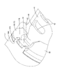
- the distal end surface in the extending direction of the extending piece 17A is cut out in a concave shape from the sheath 14 side (rear side), and a locking piece 43 (fitting portion 44) of the caulking member 40 described later is fitted. It is set as the receiving recessed part 17B.
- the notch depth of the receiving recess 17B is substantially equal to the plate thickness of a locking piece 43 (fitting portion 44) of the caulking member 40 described later.
- a small-diameter portion 34 that is externally fitted to the wire penetration portion 21 of the rubber plug 15 is provided in front of the large-diameter portion 30 (right side in FIG. 3) of the cap 17. .
- the outer diameter dimension of the small diameter part 34 is set smaller than the outer diameter dimension of the large diameter part 30.
- the cross-sectional shape of the small diameter portion 34 is formed in a trapezoidal shape with rounded corners following the outer shape of the wire penetration portion 21.
- the inner periphery of the small diameter portion 34 comes into close contact with a plurality of (three in this embodiment) small diameter portion lips 35 formed on the outer periphery of the wire penetration portion 21. Yes.
- the small-diameter portion side lip 35 protrudes outward on the outer peripheral surface of the wire penetration portion 21 and is formed along the circumferential direction of the wire penetration portion 21.
- the small diameter portion 34 of the cap 17 in a state where the small diameter portion 34 of the cap 17 is externally fitted to the electric wire penetration portion 21 of the rubber plug 15, the small diameter portion 34 changes the electric wire penetration portion 21 and the diameter of the electric wire penetration portion 21. It pushes inward in the direction. Thereby, the electric wire penetration part 21 is compressed from the outside. As a result, the first to fourth electric wire side lips 26A, 26B, 26C, and 26D formed on the inner periphery of the first to fourth through holes 22A, 22B, 22C, and 22D are connected to the first to fourth electric wires 13A and 13B. , 13C, and 13D are securely in close contact with the outer peripheries.
- the cap 17 includes a back wall 36 on the front side (right side in FIG. 3) of the small diameter portion 34.
- the first lead-out hole through which the first electric wire 13 ⁇ / b> A, the second electric wire 13 ⁇ / b> B, the third electric wire 13 ⁇ / b> C, and the fourth electric wire 13 ⁇ / b> D are led out from the cap 17.
- 37A, a second outlet hole 37B, a third outlet hole 37C, and a fourth outlet hole 37D are formed through the back wall 36.
- the rubber plug 15 is positioned relative to the cap 17.
- each of the first to fourth through holes 22A, 22B, 22C, 22D formed in the rubber plug 15 and the first to fourth lead-outs formed in the cap 17 are obtained.
- the holes 37A, 37B, 37C and 37D are aligned with each other.
- first through hole 22A and the first outlet hole 37A are aligned
- second through hole 22B and the second outlet hole 37B are aligned
- third through hole 22C and the third outlet hole 37C are aligned
- fourth through hole 22D and the fourth lead-out hole 37D are aligned with each other.
- the cap 17 is formed with two locking projections 50 ⁇ / b> A and 50 ⁇ / b> B that protrude outward in the radial direction of the small diameter portion 34 from the outer surface of the small diameter portion 34.
- the two locking projections 50A and 50B one locking projection 50A protrudes from the long side 23 side of the small diameter portion 34, and the other locking projection 50B protrudes from the short side 24 side of the small diameter portion 34.
- the two locking projections 50A and 50B have a plate shape, and have a generally rectangular shape as a whole.
- the cap 17 is formed with an anti-rotation protrusion 51 protruding upward on the outer periphery of the large diameter portion 30.
- the anti-rotation protrusion 51 has a rib shape extending in the extending direction of the large-diameter portion 30 (left-right direction in FIG. 1).
- the guide member 16 is made of synthetic resin, and as shown in FIGS. 6 and 14, a first guide hole 38A through which the first electric wire 13A is inserted and a second guide hole 38B through which the second electric wire 13B is inserted.
- the third guide hole 38C through which the third electric wire 13C is inserted and the fourth guide hole 38D through which the fourth electric wire 13D is inserted are penetrated.
- a plurality of (four in this embodiment) guide member locking portions 29 projecting inward are formed on the inner periphery of the holding portion 28 of the rubber plug 15. .
- a plurality (four in this embodiment) of guide member locking portions 39 into which each of the four guide member locking portions 29 is fitted are recessed from the outer periphery of the guide member 16. Is formed.
- Each of the four guide member locking portions 39 formed on the guide member 16 is formed at a position corresponding to each of the four guide member locking portions 29 formed on the rubber plug 15.
- Each of the four guide member locking portions 29 formed on the holding portion 28 of the rubber plug 15 engages with each of the four guide member locked portions 39 formed on the guide member 16.
- the guide member 16 is held in a state in which rotation of the guide member 16 in the circumferential direction of the guide member 16 with respect to the rubber plug 15 is suppressed. Thereby, relative positioning of the rubber stopper 15 and the guide member 16 is made.
- the first to fourth through holes 22A, 22B, 22C, 22D of the rubber plug 15 and the first to fourth guide holes 38A, 38B, 38C and 38D are matched with each other.
- first through hole 22A and the first guide hole 38A are aligned
- second through hole 22B and the second guide hole 38B are aligned
- third through hole 22C and the third guide hole 38C are aligned
- fourth through hole 22D and the fourth guide hole 38D are aligned with each other.
- a caulking member 40 is attached to the sheath 14 along with the rubber plug 15 on the rear side of the rubber plug 15 near the end portion 14 ⁇ / b> A.
- the caulking member 40 is made of metal and has a main body 41 having a substantially cylindrical shape with a C-shaped cross section (see FIG. 15). Both end edges in the circumferential direction of the main body 41 are formed in a wave shape (see FIG. 1).
- the main body 41 has elasticity in the opening / closing direction.
- Two long holes 42 extending in the circumferential direction are provided in the central portion of the main body 41 in the circumferential direction so as to penetrate the plate surface in the length direction of the main body 41 (see FIG. 2). ).
- the main body portion 41 is formed so as to extend toward the front (right side in FIG. 2) at the central portion in the circumferential direction on one end side (front side) in the length direction.
- a locking piece 43 is provided.
- the locking piece 43 is extended along the main body 41, and then the distal end side is bent outward in an L shape, and the distal end is provided on the extending piece 17A of the cap 17 described above.
- the fitting portion 44 has a width that can be fitted into the receiving recess 17B.
- the holder 52 includes a lower holder 52A and an upper holder 52B assembled to the lower holder 52A.
- the lower holder 52A includes a bottom wall and a side wall that rises upward from a side edge of the bottom wall.
- a motor wire outlet 55A from which the first electric wire 13A and the second electric wire 13B are led out and a sensor electric wire outlet 56A from which the third electric wire 13C and the fourth electric wire 13D are led out are semicircular. It is depressed and opened.
- a spare outlet for a wire (not shown) connected to a device different from the motor or the sensor is provided on a side wall different from the side wall where the motor wire outlet 55A and the sensor wire outlet 56A are formed.
- 57A is depressed in a semicircular shape and opened.
- a plurality of holding grooves 58 for holding a corrugated tube are formed on the inner peripheral surfaces of the motor electric wire outlet 55A, the sensor electric wire outlet 56A, and the auxiliary outlet 57A.
- an extended portion 59A that protrudes outward is formed on a side wall different from that in which the motor wire outlet 55A, the sensor wire outlet 56A, and the preliminary outlet 57A are formed.
- the cross-sectional shape of the extending portion 59A is formed in a substantially semicircular shape.
- the distal end side of the extending portion 59A is a caulking member holding portion 60 that holds the caulking member 40 in a state where the sheath 14 is caulked.
- the inner diameter dimension of the crimping member holding part 60 is set to a dimension in which the main body part 41 of the crimping member 40 in a state in which the sheath 14 is crimped is accommodated without rattling in the radial direction (see FIGS. 21 and 22). ).
- a holding rib 61 that protrudes inward and extends in the circumferential direction of the caulking member holding portion 60 is formed at the end edge portion of the caulking member holding portion 60.
- the holding rib 61 prevents the caulking member 40 from coming out of the caulking member holding portion 60 to the outside.
- the dimension of the crimping member holding portion 60 in the extending direction is such that the body portion 41 of the crimping member 40 is crimped to the sheath 14 and the fitting portion 44 is fitted to the receiving recess 17B of the cap 17.
- the size is set such that the fastening member 40 is accommodated without rattling in the extending direction.
- a cap holding portion 62 for holding the cap 17 is formed from the proximal end side of the extending portion 59A to a position slightly inside the extending portion 59A of the lower holder 52A.
- the large diameter part 30 of the cap 17 is accommodated in the base end side of the extending part 59A in the cap holding part 62.
- the size of the portion in which the large-diameter portion 30 is accommodated is set to a size in which the large-diameter portion 30 is accommodated without rattling in the radial direction (see FIGS. 21 and 22).
- a partition wall 63 protruding upward from the bottom wall is formed at a position inside the lower holder 52 ⁇ / b> A with respect to the side wall of the cap holding part 62, and a cap is formed in a region surrounded by the partition wall 63. 17 small-diameter portions 34 are accommodated.
- the partition wall 63 has a locking groove 64 into which the locking projections 50A and 50B are inserted at positions corresponding to the locking projections 50A and 50B of the cap 17 in a state where the cap 17 is housed inside the partition wall 63. It is formed extending downward from the upper edge of the partition wall 63.
- the locking projections 50A and 50B are inserted into the locking groove 64 in a state where the cap 17 is accommodated in the cap holding part 62. As a result, the locking protrusions 50A and 50B come into contact with the inner surface of the locking groove 64 from the thickness direction of the locking protrusions 50A and 50B, so that the relative positions of the cap 17 and the holder 52 are shifted. This is suppressed (see FIG. 21).
- the locking groove 64 is formed in the partition 63 at a position slightly inside the side wall of the lower holder 52A. Thereby, the force applied to the cap 17 is received by the side wall of the lower holder 52A.
- the width dimension of the locking groove 64 is set to be the same as or slightly larger than the thickness dimension of the locking protrusions 50A and 50B.
- An inclined surface for guiding the locking protrusions 50 ⁇ / b> A and 50 ⁇ / b> B is formed on the opening edge portion of the locking groove 64 so as to expand the diameter upward.
- the bottom wall of the lower holder 52A has a plurality of first to fourth electric wires 13A led out from the first through fourth through holes 22A, 22B, 22C, 22D of the rubber plug 15.
- 13B, 13C, 13D are formed with a first electric wire routing portion 65A and a second electric wire routing portion 65B for guiding them along a predetermined routing route.
- the first electric wire arrangement portion 65A and the second electric wire arrangement portion 65B are formed in a wall shape that rises upward from the bottom wall.
- the second electric wire routing portion 65B is provided on the side close to the sensor electric wire outlet 56A.
- the first electric wire routing portion 65A and the second electric wire routing portion 65B are formed by gently bending from a position near the cap holding portion 62 to a position near the motor wire outlet 55A.
- 65 A of 1st electric wire routing parts and the 2nd electric wire routing part 65B are formed in the substantially S shape seeing from upper direction.
- the first electric wire 13A and the second electric wire 13B are accommodated between the first electric wire arrangement portion 65A and the second electric wire arrangement portion 65B.
- the first electric wire 13A and the second electric wire 13B are routed along the routing route from the cap 17 to the motor wire outlet 55A.
- a guide protrusion 66 extending toward the sensor electric wire outlet 56A is formed at a position in the vicinity of the sensor electric wire outlet 56A.
- the third electric wire 13C and the fourth electric wire 13D led out from the cap 17 are guided by coming into contact with the second electric wire routing portion 65B and the guide projection 66, and reach from the cap 17 to the sensor electric wire outlet 56A. It is routed along the route.
- a bracket 67 is formed on the side wall of the lower holder 52A so as to protrude downward (see FIG. 19).
- a bolt insertion hole 68 is formed through the bracket 67.
- a bolt (not shown) is inserted into the bolt insertion hole 68 and screwed to the vehicle, whereby the holder 52 is fixed to the vehicle.
- the upper holder 52 ⁇ / b> B includes an upper wall and a side wall that extends downward from an edge of the upper wall.
- a plurality of lock receiving portions 70 are formed at positions corresponding to the plurality of lock portions 69 formed on the side wall of the lower holder 52A.
- the lower holder 52A and the upper holder 52B are assembled by elastically engaging the lock portion 69 and the lock receiving portion 70 (see FIG. 25).
- the motor wire outlet 55A, the sensor wire outlet 56A, the preliminary outlet 57A, and the extension of the lower holder 52A A motor wire outlet 55B, a sensor wire outlet 56B, a preliminary outlet 57B, and an extending portion 59B are formed at positions corresponding to the portion 59A.
- the extension portion 59B of the upper holder 52B is formed with a detent hole 71 penetrating at a position corresponding to the detent protrusion 51 of the cap 17 in a state where the cap 17 is accommodated in the cap holding portion 62. (See FIG. 19 and FIG. 25).
- the anti-rotation protrusion 51 is inserted into the anti-rotation hole 71, and the anti-rotation protrusion 51 contacts the inner peripheral surface of the anti-rotation hole 71, so that the cap 17 has a large diameter portion of the cap 17 in the cap holding portion 62. The rotation in the circumferential direction of 30 is suppressed.
- the cap 17 (the seal member 10) can be reliably aligned with respect to the holder 52 in the vertical direction.
- the first to fourth electric wires 13A, 13B, 13C, 13D led out from the cap 17, and the first electric wire routing portion 65A and the second electric wire routing portion 65B can be easily aligned. .
- the caulking member holding portion 60 and the cap holding portion 62 of the same form are located at positions corresponding to the caulking member holding portion 60, the cap holding portion 62, and the locking groove 64 of the lower holder 52A.
- a locking groove 64 is formed.
- the sheath 14 of the multicore cable 11 is peeled off by a known method.
- the first to fourth electric wires 13A, 13B, 13C, and 13D are led out from the end portion 14A of the sheath 14.
- the first to fourth electric wires 13A, 13B, 13C, and 13D are inserted into the first to fourth guide holes 38A, 38B, 38C, and 38D of the guide member 16, respectively.
- the fourth electric wire 13D is inserted through 38D.
- the first to fourth electric wires 13A, 13B, 13C, and 13D are inserted into the first to fourth through holes 22A, 22B, 22C, and 22D of the rubber plug 15, respectively.
- the first electric wire 13A is inserted through the first through hole 22A
- the second electric wire 13B is inserted through the second through hole 22B
- the third electric wire 13C is inserted through the third through hole 22C
- the fourth through hole is inserted.
- the fourth electric wire 13D is inserted through 22D.
- the rubber stopper 15 is moved to the position of the guide member 16.
- the first to fourth through holes 22A, 22B, 22C, 22D of the rubber plug 15 and the first to fourth guide holes 38A, 38B, 38C, 38D of the guide member 16 are aligned with each other.
- the relative positions of the rubber plug 15 and the guide member 16 are adjusted so as to be arranged.
- the guide member 16 side locking portion of the rubber plug 15 and the guide member 16 side locked portion of the guide member 16 are locked.
- each of the first to fourth through holes 22A, 22B, 22C, and 22D of the rubber plug 15 is aligned with each of the first to fourth guide holes 38A, 38B, 38C, and 38D of the guide member 16.
- the guide member 16 is held by the holding portion 28 of the rubber plug 15.
- the rubber plug 15 is moved to the end portion 14 ⁇ / b> A of the sheath 14, and the sheath outer fitting portion 18 of the rubber plug 15 is externally fitted to the end portion 14 ⁇ / b> A of the sheath 14.
- the first to fourth electric wires 13A, 13B, 13C, and 13D are inserted into the first to fourth lead-out holes 37A, 37B, 37C, and 37D of the cap 17, respectively.
- the first electric wire 13A is inserted through the first outlet hole 37A
- the second electric wire 13B is inserted through the second outlet hole 37B
- the third electric wire 13C is inserted through the third outlet hole 37C
- the fourth outlet hole is inserted.
- the fourth electric wire 13D is inserted through 37D.
- the cap 17 is moved to the position of the rubber plug 15 fitted on the end 14 ⁇ / b> A of the sheath 14.
- the first to fourth through holes 22A, 22B, 22C, 22D of the rubber plug 15 and the first to fourth outlet holes 37A, 37B, 37C, 37D of the cap 17 are aligned with each other.
- the relative positions of the rubber plug 15 and the cap 17 are adjusted so that In the above state, the rubber plug 15 side locking portion of the cap 17 and the rubber plug 15 side locked portion of the rubber plug 15 are locked.
- the first to fourth through holes 22A, 22B, 22C, 22D of the rubber plug 15 and the first to fourth outlet holes 37A, 37B, 37C, 37D of the cap 17 are aligned with each other.
- the cap 17 is fitted on the rubber plug 15. Thereafter, the cap 17 is pushed in until it comes into contact with the flange portion 19 of the rubber plug 15 (see FIG. 18).
- the extended piece 17A of the cap 17 passes through a notch 19A provided in the flange 19 of the rubber plug 15, and its tip protrudes rearward from the back of the flange 19 (FIG. 24). reference).
- the body portion 41 is attached to the sheath 14 while performing alignment so that the fitting portion 44 of the caulking member 40 is fitted into the receiving concave portion 17B of the cap 17.
- the main body 41 is attached to the sheath 14 while being elastically deformed, and in the state of being attached to the sheath 14, the sheath 14 is crimped toward the inside. Thereby, the caulking member 40 is fixed relative to the sheath 14 and the electric wire 13 in the sheath 14 is held so as not to move.
- the seal member 10 according to the present embodiment is completed, and the seal structure 12 of the multicore cable 11 is completed (see FIGS. 1 to 4).
- the caulking member 40 with the sheath 14 caulked is placed on the caulking member holding part 60 of the lower holder 52 ⁇ / b> A, and the anti-rotation protrusion of the cap 17 is placed on the cap holding part 62.
- the cap 17 is placed with the posture 51 facing upward.
- the locking protrusions 50A and 50B of the cap 17 are inserted into the locking groove 64 from above.
- the first electric wire 13A and the second electric wire 13B led out from the cap 17 are arranged between the first electric wire routing portion 65A and the second electric wire routing portion 65B, and are distributed to the motor electric wire outlet 55A.
- the third electric wire 13C and the fourth electric wire 13D led out from the cap 17 are routed to the sensor electric wire outlet 56A while being along the second electric wire routing portion 65B and the guide protrusion 66.
- the upper holder 52B is assembled to the lower holder 52A from above.
- the upper holder 52B and the lower holder 52A are assembled together by elastically engaging the lock portion 69 and the lock receiving portion 70 (see FIG. 25).
- the anti-rotation protrusion 51 of the cap 17 is fitted into the anti-rotation hole 71 of the upper holder 52B.
- the cap 17 is fitted to the rubber plug 15 while pressing the inside, and the rubber plug locking portion. 32 is locked to the locked portion 33 for the rubber plug, and the extension piece 17A is passed through the cutout portion 19A, so that the rotation is prevented, so that the cap 17 and the rubber plug 15 are relative to each other. The position is maintained.
- the crimping member 40 is crimping the sheath 14, the relative position between the crimping member 40 and the sheath 14 is maintained. Further, in the portion of the sheath 14 that is crimped by the crimping member 40 (main body portion 41), the plurality of electric wires 13 are held by the crimping member 40 so as not to move within the sheath 14.
- the cap 17 and the caulking member 40 are held at their relative positions by fitting the fitting portion 44 of the locking piece 43 into the receiving recess 17B, the rubber plug 15 and the sheath 14, and eventually The relative positions of the rubber plug 15 and the electric wire 13 are indirectly held. Therefore, even when a strong force such as twisting acts on the sheath 14 from the outside, the sealing property between the electric wire 13 and the rubber plug 15 can be maintained in a good state.
- the locking structure between the crimping member 40 and the cap 17 is such that the fitting portion 44 of the locking piece 43 extending from the main body portion 41 of the crimping member 40 is fitted into the receiving recess 17 ⁇ / b> B provided in the cap 17. Since it is a simple structure that can be simply inserted, a complicated locking structure is unnecessary, and the positioning is simple and the workability is excellent. Further, with such a configuration, the caulking member 40 and the cap 17 are reliably prevented from rotating, and the electric wire 13 is prevented from being twisted with respect to the rubber plug 15.
- the sealing performance between the plurality of electric wires 13 led out from the multicore cable 11 and the rubber plug 15 can be enhanced.
- the cap 17 and the caulking member 40 are prevented from rotating by fitting the fitting portion 44 of the locking piece 43 of the caulking member 40 into the receiving recess 17B provided in the cap 17.
- a configuration may be adopted in which a fitting portion is provided on the cap side and a receiving recess for receiving the fitting portion is provided on the caulking member side.
- a locking hole is provided in one of the cap and the caulking member, and a locking portion that can be locked with the locking hole is provided in the other.
- the relative position in the extending direction of the sheath may also be held.
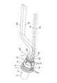
- the main body 41 of the caulking member 40 has a cylindrical shape with elastic C-section, but the main body is formed on the outer periphery of the sheath 14 as shown in FIG. It is good also as a form which crimps so that it may wind and crimps a sheath.
- the caulking member 40 is made of metal, but may be resinous, for example.
- the cap 17 and the rubber plug 15 are prevented from rotating by providing the rubber plug locking portion 32 and the rubber plug locked portion 33, but these are omitted. May be.
- the plurality of electric wires arranged in the multi-core cable 11 may be two to three, or five or more.
- the plurality of electric wires are configured to include electric wires having two types of outer diameters, but are not limited thereto, and may be configured to include electric wires having three or more types of outer diameters. Alternatively, all of the outer diameter dimensions of the plurality of electric wires may be the same.
- the guide member 16 can be omitted.
- the electric wire may be a shielded electric wire.
- the electric wire may be a stranded wire provided with a core wire in which a plurality of fine metal wires are twisted together, or may be a so-called single core wire having a metal rod as a core wire.
- arbitrary electric wires can be appropriately selected as necessary.
- the multi-core cable 11 may be a so-called cabtyre cable, or may be a multi-core shielded electric wire in which the outer periphery of a plurality of electric wires is surrounded by a shield layer.
- any multi-core cable 11 can be appropriately selected as necessary.
- any liquid such as water, oil, organic solvent, or the like can be sealed as necessary.
- the seal member 10 is assembled by assembling the guide member 16, the rubber plug 15, the cap 17, and the caulking member 40 in this order to the multicore cable 11 with the sheath 14 peeled off. And the sealing structure 12 of the multicore cable 11 is formed.
- the present invention is not limited to this, and a plurality of wires of the multicore cable 11 in which the sheath 14 is peeled off from the seal member 10 assembled in advance.
- the multi-core cable 11 and the seal member 10 may be assembled by inserting the cable.
- a protrusion 60A that fits into the long hole 42 is provided at a position corresponding to the long hole 42 in the state where the crimping member 40 is accommodated in the crimping member holding part 60 of the lower holder 52A. It is good also as a structure which hold
- Seal member 11 Multi-core cable 12: Seal structure 13: Electric wire 14: Sheath 15: Rubber plug 16: Guide member 17: Cap 17A: Extension piece (locked portion) 17B: Receiving recess (locked portion) 18: Sheath outer fitting part 19: Flange part 19A: Notch 21: Electric wire penetration part 28: Holding part 30: Large diameter part 34: Small diameter part 40: Clamping member 41: Main body part 43: Locking piece (locking part) ) 44: Fitting portion (locking portion)
Landscapes
- Installation Of Indoor Wiring (AREA)
- Connector Housings Or Holding Contact Members (AREA)
Abstract
第1~第4電線13A,13B,13C,13Dがシース14で包囲されると共にシース14の端部14Aから第1~第4電線13A,13B,13C,13Dが導出された多芯ケーブル11と、第1~第4電線13A,13B,13C,13Dのそれぞれが貫通されると共にシース14の端部14Aに外嵌されるゴム栓15と、ゴム栓15に外嵌されてゴム栓15を内方に押圧するキャップ17と、ゴム栓15と並んで配されてシース14に加締められる加締め部材40と、を備え、加締め部材40は係止片43、嵌合部44を有すると共にキャップ17は延出片17A、受け凹部17Bを有し、係止片43の嵌合部44と延出片17Aの受け凹部17Bとが係止することで加締め部材40とゴム栓15との相対的な位置が保持されるようになっている。
Description
本明細書に開示される技術は、多芯ケーブルのシール構造、及び、シール部材に関する。
従来、複数の電線を一括して防水処理する方法として、複数の電線がそれぞれ挿通される複数の電線挿通孔を有するゴム栓が知られている。各電線の外周と、各電線挿通孔の内周とが密着することにより、各電線とゴム栓とがシールされるようになっている。
このような一括型のゴム栓を、複数の電線がシースで包囲された多芯ケーブルの端末部分に取り付ける場合には、仮想的な技術として、ゴム栓にシースの端部に外嵌されるシース外嵌部を一体に設ける構成が考えられる。また、多芯ケーブルとゴム栓とのシール性をさらに高めるために、ゴム栓全体にキャップを外嵌し、ゴム栓をシースおよび複数の電線に押圧する構成が考えられる。
しかしながら上記の仮想的な技術によると、シースに対して外部から例えば捻じるような強い力が作用した場合に、シースがゴム栓に対して周方向に位置ずれしたり、シースの中で各電線が動いて各電線がゴム栓に対して捻じれ、ひいては、電線の外周と電線挿通孔の内周との密着性が低下して、電線とゴム栓とのシール性が低下する虞がある。
本明細書に開示される技術は、上記のような事情に基づいて完成されたものであって、電線とゴム栓とのシール性を高めることができる多芯ケーブルのシール構造、及び、シール部材を提供することを目的とする。
本明細書に開示される多芯ケーブルのシール構造は、複数の電線がシースで包囲されると共に前記シースの端部から前記複数の電線が導出された多芯ケーブルと、前記複数の電線のそれぞれが貫通されると共に前記シースの端部に外嵌されるゴム栓と、前記ゴム栓に外嵌されて前記ゴム栓を内方に押圧するキャップと、前記ゴム栓と並んで配されて前記シースに加締められる加締め部材と、を備え、前記加締め部材は係止部を有すると共に前記キャップは被係止部を有し、前記係止部と前記被係止部とが係止することで前記加締め部材と前記ゴム栓との相対的な位置が保持されるようになっている。
また、本明細書に開示されるシール部材は、複数の電線がシースで包囲されると共に前記シースの端部から前記複数の電線が導出された多芯ケーブルに取り付けられるものであって、前記複数の電線のそれぞれが貫通されると共に前記シースの端部に外嵌されるゴム栓と、前記ゴム栓に外嵌されて前記ゴム栓を内方に押圧するキャップと、前記ゴム栓と並んで配されて前記シースに加締められる加締め部材と、を備え、前記加締め部材は係止部を有すると共に前記キャップは被係止部を有し、前記係止部と前記被係止部とが係止することで前記加締め部材と前記キャップとの相対的な位置が保持されるようになっている。
本明細書に開示される技術によれば、キャップは、ゴム栓に外嵌されてゴム栓を内方に押圧しているから、キャップとゴム栓とは相対的な位置が保持されている。一方、加締め部材はシースを加締めているから、加締め部材とシースとは相対的な位置が保持されている。また、シースのうち加締め部材により加締められている部分においては、複数の電線は、加締め部材によりシース内で動かないように保持されている。
そして、キャップおよび加締め部材は、被係止部および係止部が係止することで相対的な位置が保持されているから、結局、キャップに保持されたゴム栓、および、加締め部材に加締められたシースひいては電線の相対的位置が、間接的に保持されることとなる。従って、外部からシースに対して例えば捻るような強い力が作用した場合でも、電線とゴム栓とのシール性を良好な状態に保つことができる。
上記多芯ケーブルのシール構造、及び、シール部材は、以下の構成を備えていてもよい。
加締め部材はシースを加締める本体部を備え、係止部は、本体部からキャップに向けて延出された係止片であり、被係止部は、係止片を嵌め入れる受け凹部であり、係止片と受け凹部とが係止することで加締め部材とキャップとが回り止めされている構成としてもよい。
上記の態様によれば、簡単な構成で、かつ、位置合わせを容易に行いつつ加締め部材の係止片をキャップの受け凹部に嵌め入れて、本体部をシースに取り付けることができる。また、加締め部材とキャップとが回り止めされるから、電線がゴム栓に対して捻じれることが抑制される。
加締め部材は、シースの外周に沿う断面C字形状の筒状をなしてシースを加締める本体部を備える構成としてもよい。
また、加締め部材は、シースの外周に巻きつくように圧着されてシースを加締める本体部を備える構成としてもよい。
本明細書に開示される技術によれば、多芯ケーブルから導出された複数の電線とゴム栓とのシール性を高めることができる。
一実施形態を、図1ないし図26を参照しつつ説明する。本実施形態は、例えば、車両(図示せず)に搭載された、電気パーキングブレーキ用のワイヤーハーネスに使用することができる。なお、以下の説明において、図1における右側を前方とし、左側を後方とする。また、図3における上側を上方とし、下側を下方とする。さらに、複数の同一部材については、一の部材に符号を付し、他の部材については符号を省略することがある。
(多芯ケーブル11)
図3~図4および図16~図18に示すように、本実施形態に係る多芯ケーブル11は、複数の電線13A,13B,13C,13D(本実施形態では4つ)が絶縁性の合成樹脂製のシース14で包囲された構成となっている。電線13A,13B,13C,13Dは、金属製の芯線(図示せず)の外周が合成樹脂製の絶縁被覆(図示せず)で覆われた構成となっている。多芯ケーブル11の断面形状は円形状をなしている。以下、電線13A,13B,13C,13Dを区別せずに記載する場合は、電線13とする。
図3~図4および図16~図18に示すように、本実施形態に係る多芯ケーブル11は、複数の電線13A,13B,13C,13D(本実施形態では4つ)が絶縁性の合成樹脂製のシース14で包囲された構成となっている。電線13A,13B,13C,13Dは、金属製の芯線(図示せず)の外周が合成樹脂製の絶縁被覆(図示せず)で覆われた構成となっている。多芯ケーブル11の断面形状は円形状をなしている。以下、電線13A,13B,13C,13Dを区別せずに記載する場合は、電線13とする。
図6~図7に示すように、4本の電線13A,13B,13C,13Dは、異なる外径寸法を有する2種の電線13A,13B,13C,13Dを含む。本実施形態においては、電気パーキングブレーキ用のモータに接続される第1電線13A、及び第2電線13Bと、アンチロックブレーキシステムのセンサ用の第3電線13C、及び第4電線13Dが含まれる。第1電線13A、第2電線13B、第3電線13C、及び第4電線13Dの断面形状は円形状をなしている。
第1電線13Aと第2電線13Bの外径寸法は、第3電線13Cと第4電線13Dの外径寸法よりも大きく設定されている。第1電線13Aの外径寸法と、第2電線13Bの外径寸法とは同じに設定されている。また、第3電線13Cの外径寸法と、第4電線13Dの外径寸法とは同じに設定されている。多芯ケーブル11のシース14の端部14Aからは第1電線13A、第2電線13B、第3電線13C、及び第4電線13Dが導出されて、それぞれ分岐されている。
(シール部材10)
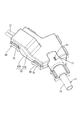
図1~図4に示すように、多芯ケーブル11のシース14の端部14Aにおいて、第1電線13A、第2電線13B、第3電線13C、及び第4電線13Dが分岐された領域には、シール部材10が取り付けられている。シール部材10によって、シース14の端部14Aから水、油等の液体がシース14内に浸入することが抑制されるようになっている。シール部材10は、シース14の端部14Aに取り付けられるゴム栓15と、ゴム栓15の内部に取り付けられるガイド部材16と、ゴム栓15に外嵌されるキャップ17と、シース14の端部寄りの位置にゴム栓15と並んで外嵌される加締め部材40と、を備える。
図1~図4に示すように、多芯ケーブル11のシース14の端部14Aにおいて、第1電線13A、第2電線13B、第3電線13C、及び第4電線13Dが分岐された領域には、シール部材10が取り付けられている。シール部材10によって、シース14の端部14Aから水、油等の液体がシース14内に浸入することが抑制されるようになっている。シール部材10は、シース14の端部14Aに取り付けられるゴム栓15と、ゴム栓15の内部に取り付けられるガイド部材16と、ゴム栓15に外嵌されるキャップ17と、シース14の端部寄りの位置にゴム栓15と並んで外嵌される加締め部材40と、を備える。
(ゴム栓15)
図3及び図4に示すように、シース14の端部14Aには、ゴム栓15が取り付けられている。ゴム栓15は、シース14の端部14Aに外嵌されるシース外嵌部18を有する。シース外嵌部18は、後方側(図3における左側)に向けて開口するフード状に形成されている。シース外嵌部18は、自然状態において実質的に円筒形状に形成されている。シース外嵌部18の後方側の端縁部には、シース外嵌部18の径方向の外方に突出するフランジ部19が形成されている(図8および図9参照)。フランジ部19の一部には、後述するキャップ17の延出片17Aを通すための切欠部19Aが設けられている(図10および図11参照)。
図3及び図4に示すように、シース14の端部14Aには、ゴム栓15が取り付けられている。ゴム栓15は、シース14の端部14Aに外嵌されるシース外嵌部18を有する。シース外嵌部18は、後方側(図3における左側)に向けて開口するフード状に形成されている。シース外嵌部18は、自然状態において実質的に円筒形状に形成されている。シース外嵌部18の後方側の端縁部には、シース外嵌部18の径方向の外方に突出するフランジ部19が形成されている(図8および図9参照)。フランジ部19の一部には、後述するキャップ17の延出片17Aを通すための切欠部19Aが設けられている(図10および図11参照)。
図3、図4及び図11に示すように、シース外嵌部18の内周には、内方に突出する複数のシース側リップ20が、シース外嵌部18の周方向に沿って環状に形成されている。シース外嵌部18がシース14の端部14Aに外嵌された状態で、シース側リップ20は、シース14の外周に密着するようになっている。これにより、ゴム栓15と、シース14との間がシールされる。
図3、図4及び図10に示すように、ゴム栓15のうち前方側(図3における右側)の端部には、第1電線13A、第2電線13B、第3電線13C、及び第4電線13Dのそれぞれが貫通される、複数(本実施形態では4つ)の貫通孔22A,22B,22C,22Dを有する電線貫通部21が設けられている。複数の貫通孔22A,22B,22C,22Dは、第1電線13Aが貫通される第1貫通孔22Aと、第2電線13Bが貫通される第2貫通孔22Bと、第3電線13Cが貫通される第3貫通孔22Cと、第4電線13Dが貫通される第4貫通孔22Dと、を含む。
図7および図10に示すように、電線貫通部21の断面形状は、角の丸められた台形状に形成されている。電線貫通部21の断面形状は、上下方向に伸びる長辺23と、この長辺23に平行であって長辺23よりも短い短辺24と、長辺23の端部と短辺24の端部とを連結する2つの斜辺25と、を備える。
電線貫通部21には、長辺23寄りの位置に、第1貫通孔22A及び第2貫通孔22Bが、長辺23の延びる方向(上下方向)に沿って並んで形成されている。また、電線貫通部21には、短辺24寄りの位置に、第3貫通孔22C及び第4貫通孔22Dが、短辺24の延びる方向(上下方向)に沿って並んで形成されている。
第1貫通孔22Aの内径寸法は、第1電線13Aの外径寸法よりもやや大きく形成されている。図8及び図10に示すように、第1貫通孔22Aの内周には、第1電線13Aの外周に密着する第1電線側リップ26A(電線側リップの一例)が、第1貫通孔22Aの周方向に沿って環状に形成されている。第1電線側リップ26Aは、第1貫通孔22Aの内部に第1電線13Aが貫通された状態で、第1電線13Aの外周に密着するようになっている。これより、第1電線13Aとゴム栓15との間がシールされる。
第2貫通孔22Bの内径寸法は、第2電線13Bの外径寸法よりもやや大きく形成されている。図8及び図10に示すように、第2貫通孔22Bの内周には、第2電線13Bの外周に密着する第2電線側リップ26B(電線側リップの一例)が、第2貫通孔22Bの周方向に沿って環状に形成されている。第2電線側リップ26Bは、第2貫通孔22Bの内部に第2電線13Bが貫通された状態で、第2電線13Bの外周に密着するようになっている。これにより、第2電線13Bとゴム栓15との間がシールされる。
第3貫通孔22Cの内径寸法は、第3電線13Cの外径寸法よりもやや大きく形成されている。図8及び図10に示すように、第3貫通孔22Cの内周には、第3電線13Cの外周に密着する第3電線側リップ26C(電線側リップの一例)が、第3貫通孔22Cの周方向に沿って環状に形成されている。第3電線側リップ26Cは、第3貫通孔22Cの内部に第3電線13Cが貫通された状態で、第3電線13Cの外周に密着するようになっている。これにより、第3電線13Cとゴム栓15との間がシールされる。
第4貫通孔22Dの内径寸法は、第4電線13Dの外径寸法よりもやや大きく形成されている。図8及び図10に示すように、第4貫通孔22Dの内周には、第4電線13Dの外周に密着する第4電線側リップ26D(電線側リップの一例)が、第4貫通孔22Dの周方向に沿って環状に形成されている。第4電線側リップ26Dは、第4貫通孔22Dの内部に第4電線13Dが貫通された状態で、第4電線13Dの外周に密着するようになっている。これにより、第4電線13Dとゴム栓15との間がシールされる。
図3及び図4に示すように、ゴム栓15には、シース外嵌部18の内部であって、シース側リップ20と、電線貫通部21との間の位置に、第1電線13A、第2電線13B、第3電線13C、及び第4電線13Dがそれぞれ挿通される複数(本実施形態では4つ)のガイド孔38A,38B,38C,38Dを有する、後述するガイド部材16が保持される保持部28が形成されている。
(キャップ17)
図3及び図4に示すように、ゴム栓15には合成樹脂製のキャップ17が外嵌されている。キャップ17は後方側(図3における左側)に向けて開口しており、ゴム栓15に前方側(図3における右側)から外嵌されている。
図3及び図4に示すように、ゴム栓15には合成樹脂製のキャップ17が外嵌されている。キャップ17は後方側(図3における左側)に向けて開口しており、ゴム栓15に前方側(図3における右側)から外嵌されている。
キャップ17の開口側(図3における左側)は、ゴム栓15のシース外嵌部18に外嵌される大径部30とされている。図6および図13に示すように、大径部30の断面形状は、シース外嵌部18の外形状に倣って、円形状に形成されている。
大径部30の内周は、図3および図4に示すように、シース外嵌部18の外周に形成された複数(本実施形態では3つ)の大径部側リップ31と密着するようになっている。図8及び図9に示すように、大径部側リップ31は、シース外嵌部18の外周面に、外方に突出すると共に、シース外嵌部18の周方向に沿って形成されている。大径部側リップ31と、キャップ17の大径部30の内周とが密着することにより、キャップ17の大径部30と、ゴム栓15のシース外嵌部18との間がシールされる。
また、図6及び図13に示すように、キャップ17の大径部30の内部には、キャップ17の開口方向に沿って延びるリブ状をなす複数(本実施形態では2つ)のゴム栓用係止部32が形成されている。2つのゴム栓用係止部32は、大径部30の内周において、互いに対向する位置に形成されている。
図6及び図8に示すように、ゴム栓15のシース外嵌部18及び保持部28の外周には、複数(本実施形態では2つ)のゴム栓用係止部32が嵌入される2つのゴム栓用被係止部33が、シース外嵌部18の延びる方向に沿って溝状に陥没して形成されている。2つのゴム栓用被係止部33のそれぞれは、大径部30に形成された2つのゴム栓用係止部32のそれぞれに対応する位置に形成されている。
大径部30のゴム栓用係止部32と、シース外嵌部18のゴム栓用被係止部33とが係止することにより、ゴム栓15が、キャップ17に対して、ゴム栓15の周方向について回転することが抑制されるようになっている。
図3及び図4に示すように、キャップ17の大径部30が、ゴム栓15のシース外嵌部18に外嵌された状態で、大径部30はシース外嵌部18を、シース外嵌部18の径方向の内方に押圧するようになっている。これにより、シース外嵌部18は、シース14の外周に外方から押圧されるようになっている。これにより、シース外嵌部18のシース側リップ20は、シース14の外周に確実に密着されるようになっている。
キャップ17(大径部30)の後方側の開口端縁の一部(下端部)には、後方側に向けて延出された延出片17Aが設けられている(図2および図24参照)。この延出片17Aは、上述したゴム栓15の切欠部19Aを通って、シース14側(後方側)に延びている。これにより、キャップ17がゴム栓15に対して、ゴム栓15の周方向について回転することが抑制されるようになっている。キャップ17(大径部30)の開口端縁のうち、延出片17A以外の部分は、ゴム栓15のフランジ部19に当接している(図4参照)。
延出片17Aは、内周面が大径部30の内周面と面一な曲面状とされるとともに、外周面が大径部30の外周面と面一な曲面状とされている。延出片17Aの延出寸法は、フランジ部19の厚さ寸法と後述する加締め部材40の嵌合部44(係止片43)の板厚との和とほぼ同等とされており、延出方向における先端縁(本実施形態における後方側の端縁部)は、ゴム栓15のフランジ部19よりシース14側(後方側)に突出している(図2および図24参照)。
また、延出片17Aの延出方向における先端面はシース14側(後方側)から凹状に切り欠かれており、後述する加締め部材40の係止片43(嵌合部44)を嵌め入れる受け凹部17Bとされている。受け凹部17Bの切り欠き深さは、後述する加締め部材40の係止片43(嵌合部44)の板厚とほぼ同等とされている。係止片43(嵌合部44)が受け凹部17Bに嵌め込まれることにより、加締め部材40がキャップ17に対して周方向について回転することが抑制されるようになっている。
図3及び図4に示すように、キャップ17のうち大径部30の前方(図3における右側)には、ゴム栓15の電線貫通部21に外嵌される小径部34が設けられている。小径部34の外径寸法は、大径部30の外径寸法よりも小さく設定されている。図5及び図12に示すように、小径部34の断面形状は、電線貫通部21の外形状に倣って、角の丸められた台形状に形成されている。
図3及び図4に示すように、小径部34の内周は、電線貫通部21の外周に形成された複数(本実施形態では3つ)の小径部側リップ35と密着するようになっている。図8及び図9に示すように、小径部側リップ35は、電線貫通部21の外周面に、外方に突出すると共に、電線貫通部21の周方向に沿って形成されている。小径部側リップ35と、キャップ17の小径部34の内周とが密着することにより、キャップ17の小径部34と、ゴム栓15の電線貫通部21との間がシールされる。
図3及び図4に示すように、キャップ17の小径部34が、ゴム栓15の電線貫通部21に外嵌された状態で、小径部34は電線貫通部21を、電線貫通部21の径方向の内方に押圧するようになっている。これにより、電線貫通部21は外方から圧縮される。これにより、第1~第4貫通孔22A,22B,22C,22Dの内周に形成された第1~第4電線側リップ26A,26B,26C,26Dは、第1~第4電線13A,13B,13C,13Dのそれぞれの外周に確実に密着されるようになっている。
図3及び図4に示すように、キャップ17は、小径部34の前方側(図3における右側)に奥壁36を備えている。図5および図12に示すように、奥壁36には、第1電線13A、第2電線13B、第3電線13C、及び第4電線13Dのそれぞれがキャップ17から導出される、第1導出孔37A、第2導出孔37B、第3導出孔37C、及び第4導出孔37Dが、奥壁36を貫通して形成されている。
図6に示すように、キャップ17の大径部30に形成されたゴム栓用係止部32と、ゴム栓15のシース外嵌部18に形成されたゴム栓用被係止部33とが係止することにより、キャップ17に対するゴム栓15の相対的な位置決めがなされている。これにより、図3及び図4に示すように、ゴム栓15に形成された第1~第4貫通孔22A,22B,22C,22Dのそれぞれと、キャップ17に形成された第1~第4導出孔37A,37B,37C,37Dのそれぞれとが、整合するようになっている。詳細に説明すると、第1貫通孔22Aと第1導出孔37Aとが整合し、第2貫通孔22Bと第2導出孔37Bとが整合し、第3貫通孔22Cと第3導出孔37Cとが整合し、第4貫通孔22Dと第4導出孔37Dとが整合するようになっている。
図5および図12に示すように、キャップ17には、小径部34の外面から小径部34の径方向外方に突出する2つの係止突起50A,50Bが形成されている。2つの係止突起50A,50Bのうち、一方の係止突起50Aは小径部34の長辺23側から突出しており、他方の係止突起50Bは小径部34の短辺24側から突出している。2つの係止突起50A,50Bは板状をなしており、全体として、概ね長方形状をなしている。
またキャップ17には、大径部30の外周に、上方に突出する回り止め突起51が形成されている。回り止め突起51は、大径部30の伸び方向(図1における左右方向)に延びるリブ状をなしている。
(ガイド部材16)
ガイド部材16は合成樹脂製であって、図6および図14に示すように、第1電線13Aが挿通される第1ガイド孔38Aと、第2電線13Bが挿通される第2ガイド孔38Bと、第3電線13Cが挿通される第3ガイド孔38Cと、第4電線13Dが挿通される第4ガイド孔38Dと、が貫通されている。
ガイド部材16は合成樹脂製であって、図6および図14に示すように、第1電線13Aが挿通される第1ガイド孔38Aと、第2電線13Bが挿通される第2ガイド孔38Bと、第3電線13Cが挿通される第3ガイド孔38Cと、第4電線13Dが挿通される第4ガイド孔38Dと、が貫通されている。
図6及び図11に示すように、ゴム栓15の保持部28の内周には、内方に突出する複数(本実施形態では4つ)のガイド部材用係止部29が形成されている。
ガイド部材16には、4つのガイド部材用係止部29のそれぞれが嵌入される複数(本実施形態では4つ)のガイド部材用被係止部39が、ガイド部材16の外周から陥没して形成されている。ガイド部材16に形成された4つのガイド部材用被係止部39のそれぞれは、ゴム栓15に形成された4つのガイド部材用係止部29のそれぞれと対応する位置に形成されている。
ゴム栓15の保持部28に形成された4つのガイド部材用係止部29のそれぞれと、ガイド部材16に形成された4つのガイド部材用被係止部39のそれぞれとが、係合する。これにより、ガイド部材16は、ゴム栓15に対してガイド部材16の周方向に回転することが抑制された状態で保持されるようになっている。これにより、ゴム栓15とガイド部材16との相対的な位置決めがなされる。この結果、図3及び図4に示すように、ゴム栓15の第1~第4貫通孔22A,22B,22C,22Dのそれぞれと、ガイド部材16の第1~第4ガイド孔38A,38B,38C,38Dのそれぞれとが、整合するようになっている。詳細に説明すると、第1貫通孔22Aと第1ガイド孔38Aとが整合し、第2貫通孔22Bと第2ガイド孔38Bとが整合し、第3貫通孔22Cと第3ガイド孔38Cとが整合し、第4貫通孔22Dと第4ガイド孔38Dとが整合するようになっている。
(加締め部材40)
図1ないし図4に示すように、シース14には、その端部14A寄りのゴム栓15の後方側に、ゴム栓15と並んで加締め部材40が取り付けられている。加締め部材40は、金属製で、断面C字形状の略筒状をなす本体部41を有している(図15参照)。本体部41のうち、周方向における両端縁は、波型に形成されている(図1参照)。本体部41は開閉方向に弾性を有する。
図1ないし図4に示すように、シース14には、その端部14A寄りのゴム栓15の後方側に、ゴム栓15と並んで加締め部材40が取り付けられている。加締め部材40は、金属製で、断面C字形状の略筒状をなす本体部41を有している(図15参照)。本体部41のうち、周方向における両端縁は、波型に形成されている(図1参照)。本体部41は開閉方向に弾性を有する。
本体部41のうち、周方向における中央部には、周方向に沿う長孔42が、本体部41の長さ方向に並んでその板面を貫通して2つ設けられている(図2参照)。
また、本体部41の長さ方向における一端側(前方側)の周方向の中央部には、図2および図24に示すように、前方(図2の右側)に向けて延出形成された係止片43が設けられている。この係止片43は、本体部41に沿って延出された後、先端側が外側に向けてL字形状に屈曲されており、その先端が上述したキャップ17の延出片17Aに設けられた受け凹部17Bにぴったり嵌め入れられる幅寸法の嵌合部44とされている。
(ホルダ52)
シース14の端部にシール部材10が取り付けられた多芯ケーブル11は、ホルダ52内に装着される。
シース14の端部にシール部材10が取り付けられた多芯ケーブル11は、ホルダ52内に装着される。
ホルダ52は、図19に示すように、下ホルダ52Aと、この下ホルダ52Aに組み付けられる上ホルダ52Bと、を備える。
(下ホルダ52A)
図19及び図2に示すように、下ホルダ52Aは、底壁と、底壁の側縁から上方に立ち上がる側壁と、を備える。側壁には、第1電線13A及び第2電線13Bが導出されるモータ用電線導出口55Aと、第3電線13C及び第4電線13Dが導出されるセンサ用電線導出口56Aとが、半円形状に陥没して開口されている。また、モータ用電線導出口55A及びセンサ用電線導出口56Aが形成された側壁とは異なる側壁には、モータ又はセンサと異なる機器に接続される電線(図示せず)のための、予備導出口57Aが半円形状に陥没して開孔されている。
図19及び図2に示すように、下ホルダ52Aは、底壁と、底壁の側縁から上方に立ち上がる側壁と、を備える。側壁には、第1電線13A及び第2電線13Bが導出されるモータ用電線導出口55Aと、第3電線13C及び第4電線13Dが導出されるセンサ用電線導出口56Aとが、半円形状に陥没して開口されている。また、モータ用電線導出口55A及びセンサ用電線導出口56Aが形成された側壁とは異なる側壁には、モータ又はセンサと異なる機器に接続される電線(図示せず)のための、予備導出口57Aが半円形状に陥没して開孔されている。
モータ用電線導出口55A、センサ用電線導出口56A、及び予備導出口57Aの内周面には、図示しないコルゲートチューブを保持するための複数の保持溝58が形成されている。
下ホルダ52Aの側壁のうち、モータ用電線導出口55A、センサ用電線導出口56A、及び予備導出口57Aが形成されたものとは異なる側壁には、外方に突出する延出部59Aが形成されている。延出部59Aの断面形状は略半円形状に形成されている。
延出部59Aの先端側は、シース14を加締めた状態の加締め部材40が保持される加締め部材保持部60とされている。加締め部材保持部60の内径寸法は、シース14を加締めた状態の加締め部材40の本体部41が径方向にがたつくことなく収容される寸法に設定されている(図21および図22参照)。
加締め部材保持部60のうち、先端側の端縁部には、内方に突出すると共に加締め部材保持部60の周方向に延びる保持リブ61が形成されている。この保持リブ61により、加締め部材40が加締め部材保持部60から外側に抜け出ることが防止されるようになっている。
また、加締め部材保持部60の伸び方向の寸法は、加締め部材40の本体部41がシース14に加締められ、嵌合部44がキャップ17の受け凹部17Bに嵌め込まれた状態において、加締め部材40が伸び方向にがたつくことなく収容される寸法に設定されている。
延出部59Aの基端側から、下ホルダ52Aのうち延出部59Aからやや内側の位置に亘って、キャップ17が保持されるキャップ保持部62が形成されている。
キャップ保持部62のうち、延出部59Aの基端側は、キャップ17の大径部30が収容されるようになっている。この大径部30が収容される部分の寸法は、大径部30が径方向にがたつくことなく収容される寸法に設定されている(図21および図22参照)。
また、キャップ保持部62のうち、側壁よりも下ホルダ52Aの内側の位置には、底壁から上方に突出する隔壁63が形成されており、この隔壁63によって囲まれた領域内には、キャップ17の小径部34が収容されるようになっている。隔壁63には、キャップ17が隔壁63の内部に収容された状態で、キャップ17の係止突起50A,50Bに対応する位置に、係止突起50A,50Bが挿入される係止溝64が、隔壁63の上端縁から下方に延びて形成されている。
キャップ保持部62にキャップ17が収容された状態で、係止突起50A,50Bは係止溝64の内部に挿入されている。これにより、係止突起50A,50Bが、係止溝64の内側面に対して、係止突起50A,50Bの厚み方向から当接することにより、キャップ17とホルダ52との相対的な位置がずれることが抑制されるようになっている(図21参照)。
係止溝64は、隔壁63のうち、下ホルダ52Aの側壁のやや内側の位置に形成されている。これにより、キャップ17に加えられた力が、下ホルダ52Aの側壁によって受けられるようになっている。
係止溝64の幅寸法は、係止突起50A、50Bの厚さ寸法と、同じか、やや大きく設定されている。係止溝64の開口縁部には、係止突起50A、50Bをガイドするための傾斜面が、上方に拡径して形成されている。
図19ないし図21に示すように、下ホルダ52Aの底壁には、ゴム栓15の第1?第4貫通孔22A,22B,22C,22Dから導出された複数の第1~第4電線13A,13B,13C,13Dを所定の配索経路にガイドするための、第1電線配索部65A及び第2電線配索部65Bが形成されている。第1電線配索部65A及び第2電線配索部65Bは、底壁から上方に立ち上がる壁状に形成されている。第2電線配索部65Bは、センサ用電線導出口56Aに近い側に設けられている。
第1電線配索部65A及び第2電線配索部65Bは、キャップ保持部62の近傍の位置から、モータ用電線導出口55Aの近傍の位置まで、緩やかに曲がって形成されている。第1電線配索部65A及び第2電線配索部65Bは、上方から見て略S字状に形成されている。第1電線配索部65Aと第2電線配索部65Bとの間には、第1電線13A、及び第2電線13Bが収容されるようになっている。これにより、第1電線13Aと第2電線13Bは、キャップ17からモータ用電線導出口55Aに至る配索経路に配索されている。
第2電線配索部65Bには、センサ用電線導出口56Aの近傍の位置に、センサ用電線導出口56Aに向かって延びるガイド突起66が形成されている。キャップ17から導出された第3電線13Cと第4電線13Dは、第2電線配索部65Bに当接すると共にガイド突起66と当接することによりガイドされ、キャップ17からセンサ用電線導出口56Aに至る配索経路に配索されている。
下ホルダ52Aの側壁には、ブラケット67が下方に突出して形成されている(図19参照)。ブラケット67にはボルト挿通孔68が貫通して形成されている。ボルト挿通孔68内にボルト(図示せず)が挿通されて、車両にねじ止めされることにより、ホルダ52が車両に対して固定されるようになっている。
(上ホルダ52B)
図19、図22及び図23に示すように、上ホルダ52Bは、上壁と、上壁の端縁から下方に延びる側壁と、を備える。上ホルダ52Bの側壁には、下ホルダ52Aの側壁に形成された複数のロック部69に対応する位置に、複数のロック受け部70が形成されている。ロック部69とロック受け部70とが弾性的に係合することにより、下ホルダ52Aと上ホルダ52Bとが組み付けられるようになっている(図25参照)。
図19、図22及び図23に示すように、上ホルダ52Bは、上壁と、上壁の端縁から下方に延びる側壁と、を備える。上ホルダ52Bの側壁には、下ホルダ52Aの側壁に形成された複数のロック部69に対応する位置に、複数のロック受け部70が形成されている。ロック部69とロック受け部70とが弾性的に係合することにより、下ホルダ52Aと上ホルダ52Bとが組み付けられるようになっている(図25参照)。
上ホルダ52Bの側壁には、下ホルダ52Aと上ホルダ52Bとが組み付けられた状態で、下ホルダ52Aの、モータ用電線導出口55A、センサ用電線導出口56A、予備導出口57A、及び延出部59Aに対応する位置に、それぞれ、モータ用電線導出口55B、センサ用電線導出口56B、予備導出口57B、及び延出部59Bが形成されている。
上ホルダ52Bの延出部59Bには、キャップ17がキャップ保持部62に収容された状態において、キャップ17の回り止め突起51に対応する位置に、回り止め孔71が貫通して形成されている(図19および図25参照)。回り止め孔71の内部に回り止め突起51が挿入されて、回り止め突起51が回り止め孔71の内周面に当接することにより、キャップ17がキャップ保持部62内においてキャップ17の大径部30の周方向に回転することが抑制されるようになっている。
また、回り止め孔71が上ホルダ52Bに設けられていることにより、ホルダ52に対して、キャップ17(シール部材10)を、上下方向について確実に位置合わせすることができる。これにより、キャップ17から導出される第1~第4電線13A,13B,13C,13Dと、第1電線配索部65A及び第2電線配索部65Bとの位置合わせも容易に行うことができる。
なお、上ホルダ52Bのうち、下ホルダ52Aの加締め部材保持部60、キャップ保持部62、係止溝64に対応する位置には、同様の形態の加締め部材保持部60、キャップ保持部62、係止溝64が形成されている。
(製造工程)
続いて、本実施形態の製造工程の一例について説明する。なお、本実施形態の製造工程は、以下の記載に限定されない。
続いて、本実施形態の製造工程の一例について説明する。なお、本実施形態の製造工程は、以下の記載に限定されない。
まず、多芯ケーブル11のシース14を、公知の手法により、皮剥ぎする。これより、シース14の端部14Aから第1~第4電線13A,13B,13C,13Dが導出された状態にする。
次に、図16に示すように、ガイド部材16の第1~第4ガイド孔38A,38B,38C,38Dのそれぞれに、第1~第4電線13A,13B,13C,13Dのそれぞれを挿通される。詳細には、第1ガイド孔38Aに第1電線13Aを挿通させ、第2ガイド孔38Bに第2電線13Bを挿通させ、第3ガイド孔38Cに第3電線13Cを挿通させ、第4ガイド孔38Dに第4電線13Dを挿通させる。
次に、ゴム栓15の第1~第4貫通孔22A,22B,22C,22Dのそれぞれに、第1~第4電線13A,13B,13C,13Dのそれぞれを挿通させる。詳細には、第1貫通孔22Aに第1電線13Aを挿通させ、第2貫通孔22Bに第2電線13Bを挿通させ、第3貫通孔22Cに第3電線13Cを挿通させ、第4貫通孔22Dに第4電線13Dを挿通させる。その後、ゴム栓15をガイド部材16の位置にまで移動させる。
次に、ゴム栓15の第1~第4貫通孔22A,22B,22C,22Dのそれぞれと、ガイド部材16の第1~第4ガイド孔38A,38B,38C,38Dのそれぞれとが、整合した配置になるように、ゴム栓15とガイド部材16との相対的な位置を調整する。上記の状態で、ゴム栓15のガイド部材16側係止部と、ガイド部材16のガイド部材16側被係止部と、を係止させる。これにより、ゴム栓15の第1~第4貫通孔22A,22B,22C,22Dのそれぞれと、ガイド部材16の第1~第4ガイド孔38A,38B,38C,38Dのそれぞれとが整合した状態で、ガイド部材16がゴム栓15の保持部28に保持される。その後、図17に示すように、ゴム栓15をシース14の端部14Aにまで移動させ、シース14の端部14Aに、ゴム栓15のシース外嵌部18を外嵌させる。
次に、キャップ17の第1~第4導出孔37A,37B,37C,37Dのそれぞれに、第1~第4電線13A,13B,13C,13Dのそれぞれを挿通させる。詳細には、第1導出孔37Aに第1電線13Aを挿通させ、第2導出孔37Bに第2電線13Bを挿通させ、第3導出孔37Cに第3電線13Cを挿通させ、第4導出孔37Dに第4電線13Dを挿通させる。その後、キャップ17を、シース14の端部14Aに外嵌されたゴム栓15の位置にまで移動させる。
次に、ゴム栓15の第1~第4貫通孔22A,22B,22C,22Dのそれぞれと、キャップ17の第1~第4導出孔37A,37B,37C,37Dのそれぞれとが、整合した配置になるように、ゴム栓15とキャップ17との相対的な位置を調整する。上記の状態で、キャップ17のゴム栓15側係止部と、ゴム栓15のゴム栓15側被係止部、を係止させる。これにより、ゴム栓15の第1~第4貫通孔22A,22B,22C,22Dのそれぞれと、キャップ17の第1~第4導出孔37A,37B,37C,37Dのそれぞれとが整合した状態で、キャップ17がゴム栓15に外嵌される。その後、キャップ17を、ゴム栓15のフランジ部19に当接するまで押し込む(図18参照)。
この時、キャップ17の延出片17Aは、ゴム栓15のフランジ部19に設けた切欠部19Aを通り、その先端部がフランジ部19の背面より後方側に突出した状態とされる(図24参照)。
次に、加締め部材40の嵌合部44がキャップ17の受け凹部17Bに嵌め込まれるように位置合わせを行いつつ、本体部41をシース14に取り付ける。本体部41は、弾性変形しつつシース14に取り付けられ、シース14に装着された状態において、シース14を内側に向けて加締めつける。これにより、加締め部材40がシース14に対して相対的に固定されるとともに、シース14内の電線13は動かないように保持される。
このようにして、本実施形態に係るシール部材10が完成すると共に、多芯ケーブル11のシール構造12が完成する(図1ないし図4参照)。
続いて、図21に示すように、下ホルダ52Aの加締め部材保持部60に、シース14を加締めた加締め部材40を載置すると共に、キャップ保持部62に、キャップ17の回り止め突起51が上方を向く姿勢でキャップ17を載置する。このとき、キャップ17の係止突起50A,50Bが係止溝64に上方から挿入されるようにする。
次に、キャップ17から導出された第1電線13A及び第2電線13Bを第1電線配索部65Aと第2電線配索部65Bとの間に配置し、モータ用電線導出口55Aへと配索する。また、キャップ17から導出された第3電線13C及び第4電線13Dを、第2電線配索部65B、及びガイド突起66に沿わせながら、センサ用電線導出口56Aへと配索する。
続いて、上ホルダ52Bを下ホルダ52Aに対して上方から組み付ける。このとき、ロック部69とロック受け部70とが弾性的に係合することにより、上ホルダ52Bと下ホルダ52Aとが一体に組み付けられる(図25参照)。またこの状態で、キャップ17の回り止め突起51は、上ホルダ52Bの回り止め孔71内に嵌め入れられている。
(本実施形態の作用、効果)
続いて、本実施形態の作用、効果について説明する。
続いて、本実施形態の作用、効果について説明する。
本実施形態の多芯ケーブル11のシール構造12、及び、シール部材10によれば、キャップ17は、ゴム栓15に対して内方を押圧しつつ外嵌されるとともに、ゴム栓用係止部32がゴム栓用被係止部33に係止し、かつ、延出片17Aが切欠部19Aに通されることにより回り止めがなされているから、キャップ17とゴム栓15とは相対的な位置が保持されている。
一方、加締め部材40はシース14を加締めているから、加締め部材40とシース14とは相対的な位置が保持されている。また、シース14のうち加締め部材40(本体部41)により加締められている部分においては、複数の電線13は、加締め部材40によりシース14内で動かないように保持されている。
そして、キャップ17および加締め部材40は、係止片43の嵌合部44が受け凹部17Bに嵌め込まれることにより相対的な位置が保持されているから、結局、ゴム栓15およびシース14、ひいては、ゴム栓15および電線13の相対的位置が間接的に保持されることとなる。従って、外部からシース14に対して例えば捻るような強い力が作用した場合でも、電線13とゴム栓15とのシール性を良好な状態に保つことができる。
また、加締め部材40とキャップ17との係止構造は、加締め部材40の本体部41から延出された係止片43の嵌合部44を、キャップ17に設けた受け凹部17Bに嵌め入れるだけの簡単な構成であるから、複雑な係止構造は不要であり、また、位置合わせが簡単で作業性に優れる。またこのような構成により、加締め部材40とキャップ17との回り止めが確実に行われ、電線13がゴム栓15に対して捻じれることが抑制される。
このように、本実施形態によれば、多芯ケーブル11から導出された複数の電線13とゴム栓15とのシール性を高めることができる。
<他の実施形態>
本明細書に開示された技術は上記記述及び図面によって説明した実施形態に限定されるものではなく、例えば次のような実施形態も本明細書に開示された技術の技術的範囲に含まれる。
本明細書に開示された技術は上記記述及び図面によって説明した実施形態に限定されるものではなく、例えば次のような実施形態も本明細書に開示された技術の技術的範囲に含まれる。
(1)上記実施形態では、キャップ17に設けた受け凹部17Bに加締め部材40の係止片43の嵌合部44を嵌め込むことにより、キャップ17と加締め部材40とを回り止めした状態とする形態を示したが、キャップ側に嵌合部を設け、加締め部材側に嵌合部を受け入れる受け凹部を設ける構成としてもよい。
(2)また、例えば、キャップおよび加締め部材のどちらか一方に係止孔を設けるとともに他方に係止孔と係止可能な係止部を設け、係止孔と係止部の係止により、シースの伸び方向における相対的な位置についても保持する構成としてもよい。
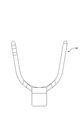
(3)上記実施形態では、加締め部材40の本体部41を、弾性を有する断面C字形状の筒状としたが、例えば、図27に示すように、本体部を、シース14の外周に巻きつくように圧着されてシースを加締める形態としてもよい。
(4)上記実施形態では、加締め部材40を金属製としたが、例えば、樹脂性でもよい。
(5)上記実施形態では、ゴム栓用係止部32とゴム栓用被係止部33とを設けることによっても、キャップ17とゴム栓15とを回り止めする構成としたが、これらは省略してもよい。
(6)多芯ケーブル11に配された複数の電線は、2本~3本、又は5本以上であってもよい。
(7)複数の電線は、2種類の外径寸法を有する電線を含む構成であったが、これに限られず、3種類以上の外径寸法を有する電線を含む構成としてもよい。あるいは、 複数の電線の外径寸法は全て同じであってもよい。
(8)ガイド部材16は省略することができる。
(9)電線はシールド電線でもよい。また、電線は、複数の金属細線が撚り合わされた芯線を備えた撚線であってもよく、また、金属棒材を芯線とするいわゆる単芯線であってもよい。このように電線としては、必要に応じて任意の電線を適宜に選択することができる。
(10)多芯ケーブル11は、いわゆるキャブタイヤケーブルであってもよく、また、複数の電線の外周がシールド層で包囲された多芯のシールド電線であってもよい。このように多芯ケーブル11としては、必要に応じて任意の多芯ケーブル11を適宜に選択することができる。
(11)本実施形態に係るシール部材10又はシール構造12によれば、水、油、有機溶媒等、必要に応じて任意の液体をシールすることができる。
(12)本実施形態においては、シース14を皮剥ぎされた多芯ケーブル11に対して、ガイド部材16、ゴム栓15、キャップ17、加締め部材40を、この順に組み付けることにより、シール部材10を組み立て、且つ、多芯ケーブル11のシール構造12を形成する構成としたが、これに限られず、予め組み付けられたシール部材10に、シース14を皮剥ぎされた多芯ケーブル11の複数の電線を挿通させることにより、多芯ケーブル11とシール部材10とを組み付けてもよい。
(13)下ホルダ52Aの加締め部材保持部60のうち、加締め部材40が収容された状態において長孔42に対応する位置に、長孔42に嵌まり込む突部60Aを設け、長孔42と突部60Aとの凹凸係合によって、加締め部材40を加締め部材保持部60内により安定的に保持させる構成としてもよい(図28参照)。
10:シール部材
11:多芯ケーブル
12:シール構造
13:電線
14:シース
15:ゴム栓
16:ガイド部材
17:キャップ
17A:延出片(被係止部)
17B:受け凹部(被係止部)
18:シース外嵌部
19:フランジ部
19A:切欠き
21:電線貫通部
28:保持部
30:大径部
34:小径部
40:加締め部材
41:本体部
43:係止片(係止部)
44:嵌合部(係止部)
11:多芯ケーブル
12:シール構造
13:電線
14:シース
15:ゴム栓
16:ガイド部材
17:キャップ
17A:延出片(被係止部)
17B:受け凹部(被係止部)
18:シース外嵌部
19:フランジ部
19A:切欠き
21:電線貫通部
28:保持部
30:大径部
34:小径部
40:加締め部材
41:本体部
43:係止片(係止部)
44:嵌合部(係止部)
Claims (8)
- 複数の電線がシースで包囲されると共に前記シースの端部から前記複数の電線が導出された多芯ケーブルと、
前記複数の電線のそれぞれが貫通されると共に前記シースの端部に外嵌されるゴム栓と、
前記ゴム栓に外嵌されて前記ゴム栓を内方に押圧するキャップと、
前記ゴム栓と並んで配されて前記シースに加締められる加締め部材と、を備え、
前記加締め部材は係止部を有すると共に前記キャップは被係止部を有し、
前記係止部と前記被係止部とが係止することで前記加締め部材と前記ゴム栓との相対的な位置が保持されるようになっている多芯ケーブルのシール構造。 - 前記加締め部材は前記シースを加締める本体部を備え、前記係止部は、前記本体部から前記キャップに向けて延出された係止片であり、
前記被係止部は、前記係止片を嵌め入れる受け凹部であり、
前記係止片と前記受け凹部とが係止することで前記加締め部材と前記キャップとが回り止めされている請求項1に記載の多芯ケーブルのシール構造。 - 前記加締め部材は、前記シースの外周に沿う断面C字形状の筒状をなして前記シースを加締める本体部を備える請求項1または請求項2に記載の多芯ケーブルのシール構造。
- 前記加締め部材は、前記シースの外周に巻きつくように圧着されて前記シースを加締める本体部を備える請求項1または請求項2に記載の多芯ケーブルのシール構造。
- 複数の電線がシースで包囲されると共に前記シースの端部から前記複数の電線が導出された多芯ケーブルに取り付けられるシール部材であって、
前記複数の電線のそれぞれが貫通されると共に前記シースの端部に外嵌されるゴム栓と、
前記ゴム栓に外嵌されて前記ゴム栓を内方に押圧するキャップと、
前記ゴム栓と並んで配されて前記シースに加締められる加締め部材と、を備え、
前記加締め部材は係止部を有すると共に前記キャップは被係止部を有し、
前記係止部と前記被係止部とが係止することで前記加締め部材と前記キャップとの相対的な位置が保持されるようになっているシール部材。 - 前記加締め部材は前記シースを加締める本体部を備え、前記係止部は、前記本体部から前記キャップに向けて延出された係止片であり、
前記被係止部は、前記係止片を嵌め入れる受け凹部であり、
前記係止片と前記受け凹部とが係止することで前記加締め部材と前記キャップとが回り止めされる請求項5に記載のシール部材。 - 前記加締め部材は、前記シースの外周に沿う断面C字形状の筒状をなして前記シースを加締める本体部を備える請求項5または請求項6に記載のシール部材。
- 前記加締め部材は、前記シースの外周に巻きつくように圧着されて前記シースを加締める本体部を備える請求項5または請求項6に記載のシール部材。
Priority Applications (2)
| Application Number | Priority Date | Filing Date | Title |
|---|---|---|---|
| CN201580069822.8A CN107112740B (zh) | 2014-12-25 | 2015-12-15 | 多芯缆线的密封结构及密封部件 |
| US15/538,417 US9837806B1 (en) | 2014-12-25 | 2015-12-15 | Seal structure for multicore cable, and seal member |
Applications Claiming Priority (2)
| Application Number | Priority Date | Filing Date | Title |
|---|---|---|---|
| JP2014-262482 | 2014-12-25 | ||
| JP2014262482A JP6210330B2 (ja) | 2014-12-25 | 2014-12-25 | 多芯ケーブルのシール構造、及び、シール部材 |
Publications (1)
| Publication Number | Publication Date |
|---|---|
| WO2016104242A1 true WO2016104242A1 (ja) | 2016-06-30 |
Family
ID=56150267
Family Applications (1)
| Application Number | Title | Priority Date | Filing Date |
|---|---|---|---|
| PCT/JP2015/085027 WO2016104242A1 (ja) | 2014-12-25 | 2015-12-15 | 多芯ケーブルのシール構造、及び、シール部材 |
Country Status (4)
| Country | Link |
|---|---|
| US (1) | US9837806B1 (ja) |
| JP (1) | JP6210330B2 (ja) |
| CN (1) | CN107112740B (ja) |
| WO (1) | WO2016104242A1 (ja) |
Cited By (1)
| Publication number | Priority date | Publication date | Assignee | Title |
|---|---|---|---|---|
| US20220131357A1 (en) * | 2020-10-22 | 2022-04-28 | Quanta Computer Inc. | Cable-Gland System For An Electronic Chassis Providing Enhanced Sealing Functionality |
Families Citing this family (4)
| Publication number | Priority date | Publication date | Assignee | Title |
|---|---|---|---|---|
| JP6686833B2 (ja) | 2016-10-12 | 2020-04-22 | 住友電装株式会社 | 導電路 |
| US10591090B2 (en) | 2017-12-28 | 2020-03-17 | Nexans | Top drive service loop clamp with torsional relief |
| US10801645B2 (en) | 2017-12-28 | 2020-10-13 | Nexans | Dynamic application cable assembly with adjustable armor clamp |
| EP4035241A4 (en) * | 2019-09-24 | 2023-10-18 | CommScope Technologies LLC | COMPOSITE CABLE SEALING |
Citations (2)
| Publication number | Priority date | Publication date | Assignee | Title |
|---|---|---|---|---|
| JPH0452387U (ja) * | 1990-09-12 | 1992-05-01 | ||
| JP2010218777A (ja) * | 2009-03-13 | 2010-09-30 | Yazaki Corp | コネクタ |
Family Cites Families (10)
| Publication number | Priority date | Publication date | Assignee | Title |
|---|---|---|---|---|
| US3328746A (en) * | 1964-08-03 | 1967-06-27 | Amp Inc | Connector seal and support |
| US3913206A (en) * | 1973-06-01 | 1975-10-21 | Hughes Aircraft Co | Method for replacement of wire seal, electrical contact |
| US4527851A (en) * | 1984-05-14 | 1985-07-09 | Allied Corporation | Electrical connector assembly having an interfacial seal |
| JP2931203B2 (ja) * | 1994-03-24 | 1999-08-09 | 矢崎総業株式会社 | 防水コネクタ |
| JP3267240B2 (ja) * | 1998-05-11 | 2002-03-18 | 住友電装株式会社 | 防水コネクタ |
| FR2782172B1 (fr) * | 1998-08-04 | 2001-11-30 | Pouyet Sa | Dispositif d'entree de cable a fibres optiques |
| CN201075651Y (zh) * | 2007-07-23 | 2008-06-18 | 中山圣马丁电子元件有限公司 | 电缆防水接头 |
| CN201323432Y (zh) * | 2008-12-06 | 2009-10-07 | 大庆油田有限责任公司 | 可分解密封电缆头 |
| CN201608491U (zh) * | 2009-12-22 | 2010-10-13 | 芜湖晶鑫灯饰有限公司 | 电线密封套 |
| CN103166163A (zh) * | 2011-12-14 | 2013-06-19 | 海洋王照明科技股份有限公司 | 电缆接头 |
-
2014
- 2014-12-25 JP JP2014262482A patent/JP6210330B2/ja active Active
-
2015
- 2015-12-15 US US15/538,417 patent/US9837806B1/en active Active
- 2015-12-15 WO PCT/JP2015/085027 patent/WO2016104242A1/ja active Application Filing
- 2015-12-15 CN CN201580069822.8A patent/CN107112740B/zh active Active
Patent Citations (2)
| Publication number | Priority date | Publication date | Assignee | Title |
|---|---|---|---|---|
| JPH0452387U (ja) * | 1990-09-12 | 1992-05-01 | ||
| JP2010218777A (ja) * | 2009-03-13 | 2010-09-30 | Yazaki Corp | コネクタ |
Cited By (2)
| Publication number | Priority date | Publication date | Assignee | Title |
|---|---|---|---|---|
| US20220131357A1 (en) * | 2020-10-22 | 2022-04-28 | Quanta Computer Inc. | Cable-Gland System For An Electronic Chassis Providing Enhanced Sealing Functionality |
| US11837860B2 (en) * | 2020-10-22 | 2023-12-05 | Quanta Computer Inc. | Cable-gland system for an electronic chassis providing enhanced sealing functionality |
Also Published As
| Publication number | Publication date |
|---|---|
| JP2016123224A (ja) | 2016-07-07 |
| CN107112740A (zh) | 2017-08-29 |
| CN107112740B (zh) | 2019-04-02 |
| US20170338641A1 (en) | 2017-11-23 |
| US9837806B1 (en) | 2017-12-05 |
| JP6210330B2 (ja) | 2017-10-11 |
Similar Documents
| Publication | Publication Date | Title |
|---|---|---|
| WO2016104242A1 (ja) | 多芯ケーブルのシール構造、及び、シール部材 | |
| JP5862710B2 (ja) | シール部材 | |
| EP3142204B1 (en) | Seal member, and seal structure for multicore cable | |
| EP2612398B1 (en) | Shield connector | |
| JP5867613B2 (ja) | ワイヤハーネス | |
| US9905337B2 (en) | Sealing structure of multicore cable | |
| US10759359B1 (en) | Holding structure for cable | |
| JP2014029780A (ja) | シールドコネクタ構造 | |
| JP2009296736A (ja) | グロメット | |
| WO2017038414A1 (ja) | シールド導電路 | |
| WO2017104392A1 (ja) | 多芯ケーブルのシール構造 | |
| WO2016104241A1 (ja) | 多芯ケーブルのシール構造 | |
| JP2010165486A (ja) | 電線接続ユニット | |
| JP5440437B2 (ja) | 電線の端末構造 | |
| EP3376620B1 (en) | Sealing structure for cable, and sealing member | |
| JP6376107B2 (ja) | シール部材、及び多芯ケーブルのシール構造 | |
| JP6070467B2 (ja) | グロメット及びグロメット付ワイヤーハーネス | |
| JP2013168257A (ja) | コネクタ及び増径電線の製造方法 |
Legal Events
| Date | Code | Title | Description |
|---|---|---|---|
| 121 | Ep: the epo has been informed by wipo that ep was designated in this application |
Ref document number: 15872811 Country of ref document: EP Kind code of ref document: A1 |
|
| WWE | Wipo information: entry into national phase |
Ref document number: 15538417 Country of ref document: US |
|
| NENP | Non-entry into the national phase |
Ref country code: DE |
|
| 122 | Ep: pct application non-entry in european phase |
Ref document number: 15872811 Country of ref document: EP Kind code of ref document: A1 |