WO2016103747A1 - 吸音材 - Google Patents
吸音材 Download PDFInfo
- Publication number
- WO2016103747A1 WO2016103747A1 PCT/JP2015/060571 JP2015060571W WO2016103747A1 WO 2016103747 A1 WO2016103747 A1 WO 2016103747A1 JP 2015060571 W JP2015060571 W JP 2015060571W WO 2016103747 A1 WO2016103747 A1 WO 2016103747A1
- Authority
- WO
- WIPO (PCT)
- Prior art keywords
- density layer
- sound
- absorbing material
- low
- material according
- Prior art date
- Legal status (The legal status is an assumption and is not a legal conclusion. Google has not performed a legal analysis and makes no representation as to the accuracy of the status listed.)
- Ceased
Links
Images


Classifications
-
- E—FIXED CONSTRUCTIONS
- E04—BUILDING
- E04B—GENERAL BUILDING CONSTRUCTIONS; WALLS, e.g. PARTITIONS; ROOFS; FLOORS; CEILINGS; INSULATION OR OTHER PROTECTION OF BUILDINGS
- E04B1/00—Constructions in general; Structures which are not restricted either to walls, e.g. partitions, or floors or ceilings or roofs
- E04B1/62—Insulation or other protection; Elements or use of specified material therefor
- E04B1/74—Heat, sound or noise insulation, absorption, or reflection; Other building methods affording favourable thermal or acoustical conditions, e.g. accumulating of heat within walls
- E04B1/82—Heat, sound or noise insulation, absorption, or reflection; Other building methods affording favourable thermal or acoustical conditions, e.g. accumulating of heat within walls specifically with respect to sound only
- E04B1/84—Sound-absorbing elements
- E04B1/86—Sound-absorbing elements slab-shaped
-
- E—FIXED CONSTRUCTIONS
- E04—BUILDING
- E04B—GENERAL BUILDING CONSTRUCTIONS; WALLS, e.g. PARTITIONS; ROOFS; FLOORS; CEILINGS; INSULATION OR OTHER PROTECTION OF BUILDINGS
- E04B1/00—Constructions in general; Structures which are not restricted either to walls, e.g. partitions, or floors or ceilings or roofs
- E04B1/62—Insulation or other protection; Elements or use of specified material therefor
- E04B1/74—Heat, sound or noise insulation, absorption, or reflection; Other building methods affording favourable thermal or acoustical conditions, e.g. accumulating of heat within walls
- E04B1/88—Insulating elements for both heat and sound
- E04B1/90—Insulating elements for both heat and sound slab-shaped
-
- G—PHYSICS
- G10—MUSICAL INSTRUMENTS; ACOUSTICS
- G10K—SOUND-PRODUCING DEVICES; METHODS OR DEVICES FOR PROTECTING AGAINST, OR FOR DAMPING, NOISE OR OTHER ACOUSTIC WAVES IN GENERAL; ACOUSTICS NOT OTHERWISE PROVIDED FOR
- G10K11/00—Methods or devices for transmitting, conducting or directing sound in general; Methods or devices for protecting against, or for damping, noise or other acoustic waves in general
- G10K11/16—Methods or devices for protecting against, or for damping, noise or other acoustic waves in general
-
- G—PHYSICS
- G10—MUSICAL INSTRUMENTS; ACOUSTICS
- G10K—SOUND-PRODUCING DEVICES; METHODS OR DEVICES FOR PROTECTING AGAINST, OR FOR DAMPING, NOISE OR OTHER ACOUSTIC WAVES IN GENERAL; ACOUSTICS NOT OTHERWISE PROVIDED FOR
- G10K11/00—Methods or devices for transmitting, conducting or directing sound in general; Methods or devices for protecting against, or for damping, noise or other acoustic waves in general
- G10K11/16—Methods or devices for protecting against, or for damping, noise or other acoustic waves in general
- G10K11/162—Selection of materials
Definitions
- the present invention relates to a sound absorbing material.
- Sound absorbing materials are widely used in houses, acoustic facilities, railway vehicles, aircraft and vehicles.
- improving the sound-absorbing characteristics in the low-frequency region has been an ongoing problem, and various proposals have been made (for example, Patent Document 1).
- Patent Document 1 In order to improve the sound absorption characteristics in the low frequency region, there is a problem that the sound absorbing material must be thickened, and the use and / or place of use of the sound absorbing material is limited. Therefore, there is a strong demand for a sound absorbing material that can achieve both excellent sound absorption characteristics in the low frequency region and thinning.
- the present invention has been made to solve the above-described conventional problems, and an object of the present invention is to provide a sound absorbing material that is thin and has excellent sound absorbing characteristics in a low frequency region.
- the sound-absorbing material of the present invention has a low-density layer and a high-density layer, the Young's modulus of the low-density layer is 100,000 Pa or less, and the overall surface density is 1.8 kg / m 2 or more.
- the thickness of the low density layer is 25 mm or less.
- the low-density layer is composed of one selected from a porous material, a gel material, and a laminate thereof.
- the low-density layer is composed of an ethylene / propylene / diene rubber open-cell foam.
- the low-density layer is composed of 0.1 to 40 parts by weight of an organic foaming agent and 2 to 40 parts by weight of an inorganic foaming agent with respect to 100 parts by weight of ethylene / propylene / diene rubber. Parts by weight, and 2 to 40 parts by weight of a foaming aid.
- the surface density of the high-density layer is 2 kg / m 2 or less.
- the high-density layer has a thickness of 50 ⁇ m to 500 ⁇ m.
- the high density layer is non-breathable.
- the high-density layer is composed of one selected from the group consisting of a metal, a resin film, paper, a rubber sheet, and a laminate thereof.
- the sound absorbing material has a total thickness of 26 mm or less.
- the high-density layer is made of metal.
- the sound-absorbing material has a sound absorption coefficient of 40% or higher for a sound of 1000 Hz or less. In another embodiment, the sound absorbing material has a sound absorption rate of sound of 600 Hz or less of 60% or more.
- a combination of a low-density layer having a specific Young's modulus and a laminated structure of a low-density layer / a high-density layer having a specific surface density as a whole is thin and has an excellent low-frequency region. It is possible to realize a sound absorbing material having the sound absorbing characteristics.
- A. 1 is a schematic sectional view of a sound absorbing material according to one embodiment of the present invention.
- the sound absorbing material 100 of this embodiment includes a low density layer 10 and a high density layer 20.
- the low density layer 10 and the high density layer 20 are laminated by any appropriate adhesive or double-sided tape (not shown).
- “low density layer” means a layer having a relatively low density in the sound absorbing material
- “high density layer” means a layer having a relatively high density, It is not based on a specific value of density.
- the sound absorbing material 100 has a total thickness of preferably 26 mm or less, more preferably 20 mm or less, and further preferably 1 mm to 15 mm. According to the present invention, it is possible to realize a sound absorbing material having a very excellent low frequency region sound absorption characteristic (low sound absorption characteristic) regardless of such a very thin thickness.
- the surface density of the sound absorbing material 100 is 1.8 kg / m 2 or more, preferably 1.8 kg / m 2 to 4 kg / m 2 . If the surface density of the sound-absorbing material is in such a range, it is possible to realize a very excellent low-frequency absorption characteristic even in applications where the thickness and weight are limited.
- the density of the sound absorbing material 100 is preferably 1000 kg / m 3 or less, more preferably 400 kg / m 3 or less, still more preferably 250 kg / m 3 or less, and particularly preferably 170 kg / m 3 or less.
- the density of the sound absorbing material 100 is preferably 100 kg / m 3 or more, and more preferably 120 kg / m 3 or more. If the density of the sound-absorbing material is in such a range, it is possible to realize a thin and very excellent bass-absorbing characteristic.
- the sound absorbing material 100 has a sound absorption rate of sound of 600 Hz or less, preferably 60% or more, more preferably 70% or more, and further preferably 80% or more. As described above, according to the present invention, it is possible to realize a sound-absorbing material having such excellent low-frequency absorption characteristics regardless of a very thin thickness.
- the sound absorption characteristics can be measured according to JIS A 1405-2.
- the high-density layer 20 has a flame retardant function, and thus the sound absorbing material 100 has a flame retardant property.
- the sound absorbing material 100 has a thermal diffusion parameter HD defined by the following formula of 0.005 (m 2 ) or more.
- the thermal diffusion parameter HD is preferably 0.010 (m 2 ) or more, more preferably 0.012 (m 2 ) or more, and further preferably 0.015 (m 2 ) or more.
- the upper limit of the thermal diffusion parameter HD is, for example, 0.3 (m 2 ).
- the thermal diffusion parameter HD is optimized to such a range, thereby realizing an excellent difficulty while realizing a thin sound absorbing material. Both the flammability and the excellent sound absorption characteristics in the low frequency region can be achieved. This is an excellent effect that cannot be realized simply by selecting the thickness and thermal conductivity (substantially constituent material) of the low-density layer and the high-density layer.
- the term [(thickness of high-density layer) ⁇ (thermal conductivity of high-density layer)] in the above formula means the ease of spreading of heat in the plane of the high-density layer, This means that the larger this is, the fewer the points that are too hot locally in the high-density layer.
- the term [(thickness of low-density layer) / (thermal conductivity of low-density layer)] in the above formula means the difficulty in transferring heat in the thickness direction of the low-density layer. This means that the low density layer is hardly heated in the thickness direction.
- the high-density layer can be hardly overheated locally and / or heat can hardly be transmitted in the thickness direction of the low-density layer.
- the high-density layer is not easily overheated locally, and heat can be hardly transmitted in the thickness direction of the low-density layer, so that the low-density layer is locally heated and further heated. Combustion of the low density layer due to heat propagating through the low density layer can be satisfactorily prevented.
- both the flame retardancy and the low-frequency sound absorption characteristics are better as the sound absorbing material is thicker,
- By optimizing the diffusion parameters it is possible to achieve excellent flame retardancy and low sound absorption characteristics in a thin sound absorbing material.
- the sound absorbing material 100 has a sound absorption rate of sound of 1000 Hz or less, preferably 40% or more, more preferably 50% or more, and further preferably 60% or more. And particularly preferably 70% or more. According to this embodiment, it is possible to achieve both excellent flame retardancy and such excellent bass absorption characteristics.
- the low density layer 10 absorbs sound by converting vibration energy of sound waves into thermal energy. Since the low density layer has an open cell structure as described later, the resonance frequency can be shifted to the low wavelength side. As a result, a very excellent bass absorption characteristic can be realized.
- the Young's modulus of the low density layer 10 is 100000 Pa or less, preferably 50000 Pa or less, and more preferably 30000 Pa or less.
- the lower limit of the Young's modulus of the low density layer is, for example, 5000 Pa. If the Young's modulus of the low-density layer is in such a range, there is an advantage that sound energy can be satisfactorily converted by converting the energy of sound into the deformation energy of the sound absorbing material.
- the Young's modulus can be measured, for example, using a dynamic viscoelasticity measuring apparatus (for example, “RSA-G2” manufactured by TA Instruments, Inc.) at a strain of 1%, a frequency of 1 Hz, room temperature, and a compression mode.
- RSA-G2 dynamic viscoelasticity measuring apparatus
- the thickness of the low density layer 10 is preferably 25 mm or less, more preferably 20 mm or less, and even more preferably 15 mm or less. On the other hand, the thickness of the low density layer 10 is preferably 1 mm or more, and more preferably 5 mm or more. In the embodiment of the present invention, it is possible to realize a very excellent bass absorption characteristic with such a thin thickness. By adopting a specific fine structure (typically a porous structure or a gel structure) using the materials described later as the low-density layer, it has achieved such excellent low-frequency absorption characteristics despite its thin thickness. can do.
- a specific fine structure typically a porous structure or a gel structure
- the surface density of the low density layer 10 is preferably 1 kg / m 2 to 3 kg / m 2 . If the surface density of the low-density layer is in such a range, the surface density of the entire sound-absorbing material can be set to a desired range by adjusting the surface density of the high-density layer. As a result, it is possible to obtain a sound absorbing material that is thin and has excellent low-frequency absorption characteristics.
- the density of the low density layer 10 is preferably 50 kg / m 3 to 130 kg / m 3 . If the density of the low-density layer is in such a range, there is an advantage that sound energy can be satisfactorily converted into deformation energy of the sound absorbing material and the resonance frequency can be adjusted to 600 Hz or less.
- the thermal conductivity of the low density layer 10 is preferably 0.2 W / m ⁇ K or less, more preferably 0.1 W / m ⁇ K or less, and even more preferably 0.05 W / m ⁇ K or less. .
- the lower limit of the thermal conductivity is, for example, 0.02 W / m ⁇ K.
- the thermal conductivity can be measured according to JIS 1412-2 (heat flow meter method). If the thermal conductivity of the low-density layer 10 is in such a range, good thermal diffusivity can be obtained while being thin. As a result, when imparting flame retardancy to the sound absorbing material, a sound absorbing material having excellent flame retardancy can be obtained.
- any appropriate material that can realize the above Young's modulus and the above-described other characteristics as necessary can be used.
- specific examples of such materials include porous materials, gel materials, and laminates thereof.
- the porous material include nonwoven fabric, glass wool, rock wool, felt material, polymer foam, and polymer monolith.
- a desired Young's modulus can be realized by adjusting the constituent material, the porosity, the pore size and / or the shape of the pore.
- the gel material include silicone gel and urethane gel.
- a desired Young's modulus or the like can be realized by adjusting a constituent material and / or a crosslinking density.
- polymer foam examples include any appropriate material obtained by foaming a polymer material and imparting a porous structure.
- specific examples of the polymer constituting the foam include polyurethane, polystyrene, polyolefin (for example, polyethylene and polypropylene), and ethylene / propylene / diene rubber (EPDM).
- EPDM ethylene / propylene / diene rubber
- Any appropriate structure may be employed as the porous structure depending on the purpose.
- each bubble formed by foaming may have an independent closed cell structure, or may have an open cell structure in which at least a part of the bubbles are continuous.
- an EPDM foam having an open cell structure hereinafter also referred to as an EPDM open cell foam
- an EPDM open cell foam will be described as a representative example of the polymer foam.
- the “open cell foam” means a foam having a structure in which at least some of the cells formed in the foam are continuous.
- the open cell foam may have an open cell structure or may have a semi-continuous and semi-closed cell structure.
- the open cell structure refers to a structure having an open cell rate of 100%.
- the semi-continuous semi-closed cell structure refers to a structure in which the lower limit of the open cell ratio exceeds 0%, preferably 10% or more, and the upper limit is less than 100%, preferably less than 98%.
- the average cell diameter of the open cell foam is preferably 50 ⁇ m or more, more preferably 100 ⁇ m or more, and further preferably 200 ⁇ m or more.
- the average cell diameter is preferably 1200 ⁇ m or less, more preferably 1000 ⁇ m or less, and still more preferably 800 ⁇ m or less.
- an average cell diameter can be calculated
- the material constituting the EPDM open-cell foam any appropriate material can be used as long as a desired thickness reduction is realized and a desired low-frequency sound absorption characteristic is obtained.
- the EPDM open-cell foam is typically 0.1 to 40 parts by weight of an organic foaming agent, 2 to 40 parts by weight of an inorganic foaming agent, and 2 parts by weight of a foaming aid with respect to 100 parts by weight of EPDM. Parts to 40 parts by weight.
- EPDM is a rubber obtained by copolymerization of ethylene, propylene, and dienes, and vulcanization with a vulcanizing agent is carried out by introducing unsaturated bonds by further copolymerizing dienes with the ethylene-propylene copolymer.
- diene Any appropriate diene can be used as the diene. Specific examples include 5-ethylidene-2-norbornene, 1,4-hexadiene, and dicyclopentadiene.
- organic foaming agent can be used as the organic foaming agent.
- organic foaming agent include azo compounds, N-nitroso compounds, hydrazide compounds, semicarbazide compounds, fluorinated alkanes, and triazole compounds.
- specific examples of the azo compound include azodicarboxylic acid amide (ADCA), barium azodicarboxylate, azobisisobutyronitrile (AIBN), azocyclohexylnitrile, and azodiaminobenzene.
- ADCA azodicarboxylic acid amide
- AIBN azobisisobutyronitrile
- azocyclohexylnitrile azocyclohexylnitrile
- azodiaminobenzene azodiaminobenzene.
- N-nitroso compound examples include N, N ′ ′-dinitrosopentamethylenetetramine (DTP), N, N ′ ′-dimethyl-N, N ′ ′-dinitrosotephthalamide, and trinitrosotrimethyltriamine.
- DTP N, N ′ ′-dinitrosopentamethylenetetramine
- N, N ′ ′-dimethyl-N, N ′ ′-dinitrosotephthalamide examples include trinitrosotrimethyltriamine.
- hydrazide compound examples include 4,4 ′ ′-oxybis (benzenesulfonylhydrazide) (OBSH), paratoluenesulfonylhydrazide, diphenylsulfone-3,3′-disulfonylhydrazide, 2,4-toluenedisulfonylhydrazide, Examples thereof include p, p-bis (benzenesulfonylhydrazide) ether, benzene-1,3-disulfonylhydrazide, and allylbis (sulfonylhydrazide).
- OBSH 4,4 ′ ′-oxybis (benzenesulfonylhydrazide)
- paratoluenesulfonylhydrazide diphenylsulfone-3,3′-disulfonylhydrazide
- 2,4-toluenedisulfonylhydrazide examples thereof include
- the semicarbazide compound include p-toluylenesulfonyl semicarbazide and 4,4 ′ ′-oxybis (benzenesulfonyl semicarbazide).
- the fluorinated alkane include trichloromonofluoromethane and dichloromonofluoromethane.
- Specific examples of the triazole compound include 5-morpholyl-1,2,3,4-thiatriazole.
- an azo compound or an N-nitroso compound is used, and more preferably, azodicarboxylic acid amide (ADCA) or N, N′-dinitrosopentamethylenetetramine (DTP) is used.
- ADCA azodicarboxylic acid amide
- DTP N′-dinitrosopentamethylenetetramine
- thermoly expandable fine particles in which a heat-expandable substance is enclosed in microcapsules may be used.
- thermally expandable fine particles for example, commercially available products such as microspheres (trade name, manufactured by Matsumoto Yushi Co., Ltd.) may be used.
- An organic foaming agent may be used independently and may use 2 or more types together.
- any appropriate inorganic foaming agent can be used as the inorganic foaming agent.
- the inorganic foaming agent include hydrogen carbonates such as sodium hydrogen carbonate and ammonium hydrogen carbonate, carbonates such as sodium carbonate and ammonium carbonate, nitrites such as sodium nitrite and ammonium nitrite, and hydrogen such as sodium borohydride. Examples thereof include boron halide salts and azides.
- a bicarbonate is used, and more preferably, sodium bicarbonate is used.
- An inorganic foaming agent may be used independently and may use 2 or more types together.
- any appropriate combination can be adopted as the combination of the organic foaming agent and the inorganic foaming agent.
- a combination of azodicarboxylic acid amide (ADCA) or N, N′-dinitrosopentamethylenetetramine (DTP) as the organic foaming agent and sodium hydrogen carbonate as the inorganic foaming agent can be used.
- the blending ratio of the organic foaming agent and the inorganic foaming agent is preferably 20/1 to 0.1 / 1 by weight ratio, more preferably 9/1 to 1/1, and more preferably 6/1 to 1/1.
- organic foaming agent exceeds the above blending ratio, the resulting foam may become closed cells.
- the organic foaming agent is less than the above blending ratio, the foam may not be obtained due to outgassing.
- EPDM open-cell foam is blended with the above-mentioned EPDM, organic foaming agent, inorganic foaming agent, foaming aid, filler, softener, vulcanizing agent, vulcanization accelerator, etc., and vulcanized and foamed. It can be obtained by (vulcanization foaming).
- the EPDM open-cell foam may contain any appropriate additive depending on the purpose.
- the additive include a reinforcing material, a vulcanization aid, a lubricant, a plasticizer, an antioxidant, an antioxidant, a pigment, a colorant, an antifungal agent, and a flame retardant.
- vulcanization foaming may be performed by molding the admixture into a sheet shape by calendar molding or extrusion molding, or by vulcanization foaming, or by injection molding or press molding, It may be molded into a complicated shape and vulcanized and foamed.
- the heating temperature in vulcanization foaming can be appropriately set according to the vulcanization start temperature of the blended vulcanizing agent, the foaming temperature of the blending foaming agent, and the like.
- the vulcanization temperature is, for example, 450 ° C. or lower, preferably 100 ° C. to 350 ° C., and more preferably 120 ° C. to 250 ° C.
- the vulcanized foam as described above softens the admixture, while the organic foaming agent and the inorganic foaming agent expand, and the vulcanization proceeds while forming a foamed structure. It is formed. Furthermore, by setting the vulcanization temperature as described above, in the vulcanization foaming, first, the organic foaming agent foams (primary foaming), and then the inorganic foaming agent foams at a temperature higher than the primary foaming. (Secondary foaming) Two-stage foaming is performed.
- the foaming ratio (density ratio before and after foaming) of the obtained EPDM open-cell foam can be set preferably 10 to 30 times, more preferably 10 to 20 times.
- the expansion ratio can be controlled by adjusting the blending ratio of the organic foaming agent and the inorganic foaming agent, the vulcanization foaming time, the temperature, and the like.
- polymer monolith body examples include a silicone monolith body as described in JP-A-2014-61457. This publication is incorporated herein by reference in its entirety.
- the surface density of the high-density layer 20 is preferably 2 kg / m 2 or less, more preferably 1.5 kg / m 2 or less, and even more preferably 1.2 kg / m 2 or less.
- the surface density of the high density layer 20 is preferably at 0.2 kg / m 2 or more, more preferably 0.4 kg / m 2 or more. If the surface density is in such a range, the surface density of the entire sound-absorbing material can be set to a desired range even when the low-density layer as described above is used. As a result, it is possible to obtain a sound absorbing material that is thin and has excellent low-frequency absorption characteristics.
- the density of the high density layer 20 is preferably 500kg / m 3 ⁇ 10000kg / m 3. If the density of the high-density layer is in such a range, there is an advantage that the surface density of the entire sound-absorbing material can be set to a desired range by using a thinner and cheaper high-density layer.
- the thickness of the high-density layer 20 is preferably 10 ⁇ m to 1000 ⁇ m, more preferably 50 ⁇ m to 500 ⁇ m. If the thickness of the high-density layer is in such a range, a desired density and areal density can be realized as the entire sound-absorbing material.
- the thermal conductivity of the high-density layer 20 is preferably 10 W / m ⁇ K to 500 W / m ⁇ K. If the thermal conductivity of the high-density layer is within such a range, the thermal diffusion parameter HD should be within a desired range using a thinner and cheaper high-density layer when imparting flame retardancy to the sound absorbing material. There is an advantage that can be.
- the high-density layer As a material constituting the high-density layer, any appropriate material can be used as long as a desired thinning is realized and a desired bass absorption characteristic is obtained.
- the high density layer is typically non-breathable. Since the high-density layer is non-breathable, there is an advantage that sound energy can be satisfactorily converted into sound-transforming energy and sound can be absorbed.
- the air permeability can be measured by JIS P8117 (Gurley test method).
- materials constituting the high-density layer include metals, resin films, paper, rubber sheets, and laminates thereof.
- the metal include aluminum, stainless steel (SUS), iron, and copper.
- the metal can typically be used as a metal foil.
- the resin constituting the resin film include polyester resins such as polyethylene terephthalate (PET), polybutylene terephthalate (PBT), and polyethylene naphthalate (PEN), polyolefin resins such as polyethylene (PE) and polypropylene (PP), Examples thereof include polycarbonate (PC), acrylic resin, polystyrene (PS), polyvinyl chloride (PVC), and acrylonitrile-butadiene-styrene copolymer resin (ABS).
- PET polyethylene terephthalate
- PBT polybutylene terephthalate
- PEN polyethylene naphthalate
- PC polycarbonate
- acrylic resin polystyrene
- PVC polyvinyl chloride
- ABS acrylon
- the high-density layer 20 has a flame retardant function. That is, the high-density layer 20 not only contributes to the low-frequency sound absorption characteristics, but can impart flame retardancy to the entire sound-absorbing material (substantially protect the low-density layer from heat and prevent combustion). .
- the high-density layer 20 by appropriately setting the combination of the high-density layer and the low-density layer that can realize the above-mentioned desired range of heat diffusion parameters, by stacking the high-density layer, flame retardancy and low-frequency absorption characteristics can be achieved. Both can be improved. Such an effect is particularly remarkable when the thickness of the low density layer is thin.
- the high-density layer 20 can be typically made of metal.
- Thickness Measured using a thickness gauge (2) Area density About the sound-absorbing material obtained in the examples and comparative examples, and the low-density layer (foam) and the high-density layer used in the examples and comparative examples, these were formed with a ⁇ 100 mm punching blade and a ⁇ 100 mm cylinder The weight of the sample punched out was measured with an electronic balance and determined by dividing by an area of 0.00785 (m 2 ). Note that 0.00785 (m 2 ) is the area of a circle of ⁇ 100 mm. (3) Density The density was obtained by dividing the surface density obtained in (2) above by the thickness measured in (1) above.
- Examples 21 to 30 and Comparative Examples 18 to 22 were evaluated as follows. Samples were produced in the same manner as described above from the sound absorbing materials obtained in the examples and comparative examples, the sound absorption rate in the frequency range of 100 Hz to 1000 Hz was measured, and the maximum sound absorption rate in the range was evaluated according to the following criteria. . ⁇ ... Sound absorption coefficient is 45% or more ⁇ ... Sound absorption coefficient is 40% or more and less than 45% ⁇ ...
- the sound absorbing materials obtained in Examples 21 to 30 and Comparative Examples 18 to 22 were cut into 182 mm ⁇ 257 mm as samples, and the samples were held on a sample holding table inclined at 45 ° as shown in FIG.
- the fuel container made of iron, 17.5 ⁇ ⁇ 7.1
- the mounting table was made of a material having low thermal conductivity (cork in this case). 0.55 cc of pure ethyl alcohol was added as a fuel to the fuel container, ignited, and left to stand until the fuel was burned out. Flame retardancy was evaluated according to the following criteria.
- Example 1 to 20 and Comparative Examples 1 to 17 The low-density layer and the high-density layer having the configuration shown in Table 1 were bonded together by the method shown in Table 1 to produce each sound absorbing material. The obtained sound absorbing material was subjected to the above evaluation. The results are shown in Table 1.
- Table 1 for example, the description “sound absorption rate 0.8” indicates that the sound absorption rate is 80%.
- SUS indicates stainless steel (SUS304H).
- Al indicates aluminum (A1050P).
- PET indicates “Sunroid PET Ace” manufactured by Sumitomo Bakelite.
- Double-sided tape” indicates “No.
- EH2200 represents “Eptosealer EH2200” manufactured by Nitto Denko Corporation
- EC-100 represents “Eptosealer EC-100” manufactured by Nitto Denko Corporation
- EC-200 represents “Eptosealer EC-200” manufactured by Nitto Denko Corporation.
- EE1000 indicates “Epto Sealer EE1000” manufactured by Nitto Denko Corporation
- EV1000 indicates “Epto Sealer EV1000” manufactured by Nitto Denko Corporation, and “No.
- Nitto Denko's “Eptosealer EH-2200” is used as the low-density layer
- aluminum (A1050P) foil is used as the high-density layer
- these are affixed via double-sided tape (“AS-1302-P12” from Nitto Denko)
- a sound absorbing material was produced.
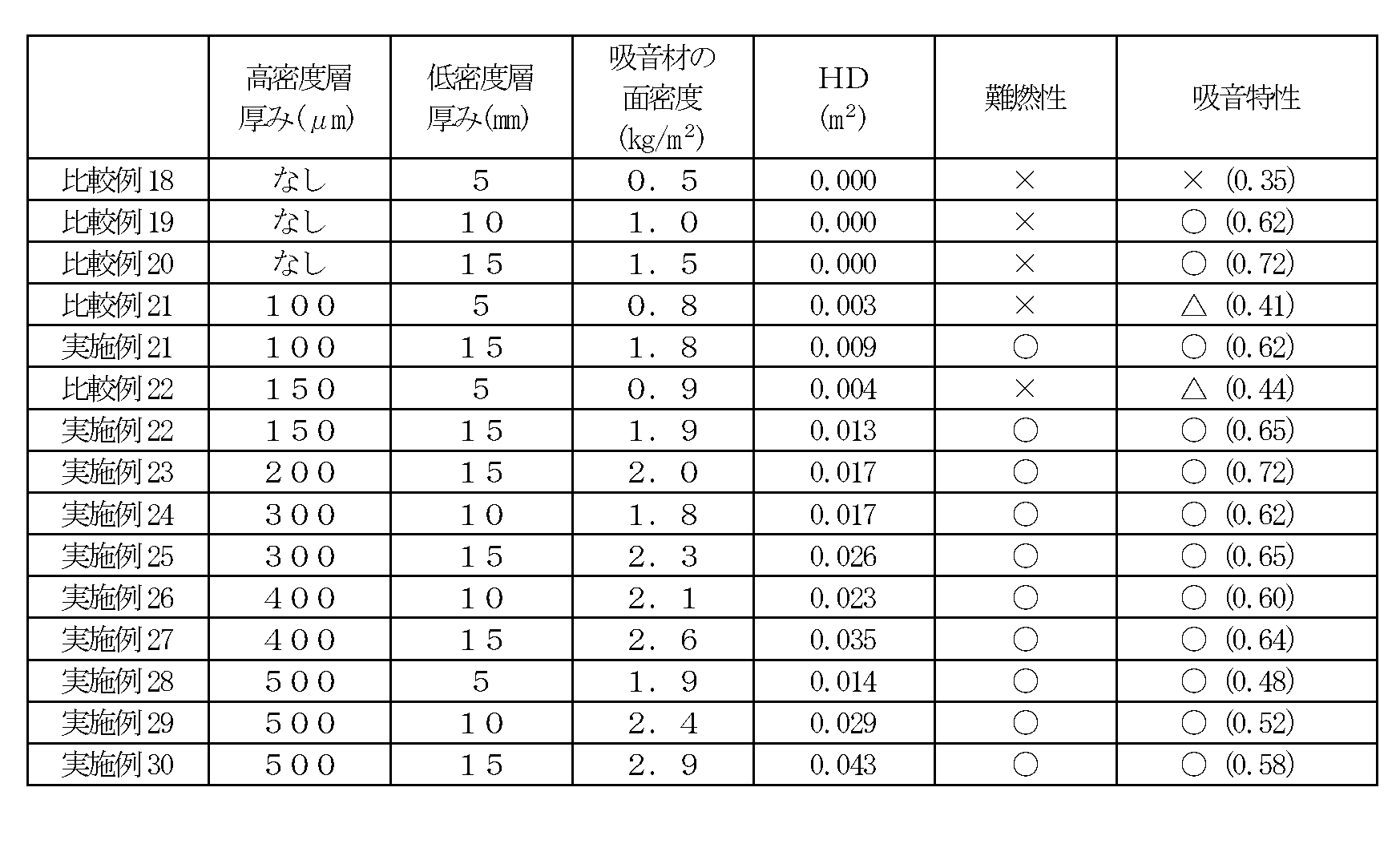
- a sound absorbing material was produced by combining a low density layer and a high density layer having thicknesses as shown in Table 2. The obtained sound absorbing material was subjected to the above evaluation. The results are shown in Table 2.
- the sound absorbing material of the example of the present invention is remarkably superior in the maximum sound absorption rate of sound of 600 Hz or less as compared with the sound absorbing material of the comparative example. Further, as is apparent from Table 2, it can be seen that the sound absorbing material of the example of the present invention is excellent in both flame retardancy and low sound absorption characteristics by optimizing the heat diffusion parameter. From this, it is understood that both the flame retardancy and the low-frequency sound absorption characteristics are improved by arranging the high-density layer.
- the sound absorbing material of the present invention can be suitably used for automobiles, railways, aircraft, home appliances, and mobile devices.
Landscapes
- Physics & Mathematics (AREA)
- Engineering & Computer Science (AREA)
- Acoustics & Sound (AREA)
- Architecture (AREA)
- Multimedia (AREA)
- Electromagnetism (AREA)
- Civil Engineering (AREA)
- Structural Engineering (AREA)
- Laminated Bodies (AREA)
Abstract
薄型で、かつ、優れた低周波領域の吸音特性を有する吸音材が提供される。本発明の吸音材は、低密度層と高密度層とを有する。低密度層のヤング率は100000Pa以下である。本発明の吸音材の全体の面密度は1.8kg/m2以上である。1つの実施形態においては、本発明の吸音材は、総厚みが26mm以下であり、600Hz以下の音の吸音率が60%以上である。
Description
本発明は、吸音材に関する。
吸音材は、家屋、音響施設、鉄道車両、航空機および車両などに幅広く利用されている。吸音材においては、低周波領域の吸音特性を改善することが継続的な課題となっており、種々の提案がなされている(例えば、特許文献1)。しかし、低周波領域の吸音特性を改善しようとすると、吸音材を分厚くしなければならず、吸音材の用途および/または使用場所が制限されるという問題がある。したがって、優れた低周波領域の吸音特性と薄型化を両立し得る吸音材が強く望まれている。
本発明は上記従来の課題を解決するためになされたものであり、その目的とするところは、薄型で、かつ、優れた低周波領域の吸音特性を有する吸音材を提供することにある。
本発明の吸音材は、低密度層と高密度層とを有し、該低密度層のヤング率が100000Pa以下であり、全体の面密度が1.8kg/m2以上である。
1つの実施形態においては、上記低密度層の厚みは25mm以下である。
1つの実施形態においては、上記低密度層は、多孔質材料、ゲル材料およびこれらの積層体から選択される1つで構成されている。
1つの実施形態においては、上記低密度層は、エチレン・プロピレン・ジエンゴム連続気泡発泡体で構成されている。1つの実施形態においては、上記低密度層は、エチレン・プロピレン・ジエンゴム100重量部に対して、有機系発泡剤を0.1重量部~40重量部、無機系発泡剤を2重量部~40重量部、および発泡助剤を2重量部~40重量部含む。
1つの実施形態においては、上記高密度層の面密度は2kg/m2以下である。
1つの実施形態においては、上記高密度層の厚みは50μm~500μmである。
1つの実施形態においては、上記高密度層は非通気性である。
1つの実施形態においては、上記高密度層は、金属、樹脂フィルム、紙、ゴムシートおよびこれらの積層体からなる群から選択される1つで構成されている。
1つの実施形態においては、上記吸音材は、総厚みが26mm以下である。
1つの実施形態においては、上記高密度層は難燃機能を有し、上記吸音材は下記式で定義される熱拡散パラメーターHDが0.005(m2)以上である:
HD=[(高密度層の厚み)×(高密度層の熱伝導率)]×[(低密度層の厚み)/(低密度層の熱伝導率)]。
1つの実施形態においては、上記高密度層は金属で構成されている。
1つの実施形態においては、上記吸音材は、1000Hz以下の音の吸音率が40%以上である。別の実施形態においては、上記吸音材は、600Hz以下の音の吸音率が60%以上である。
1つの実施形態においては、上記低密度層の厚みは25mm以下である。
1つの実施形態においては、上記低密度層は、多孔質材料、ゲル材料およびこれらの積層体から選択される1つで構成されている。
1つの実施形態においては、上記低密度層は、エチレン・プロピレン・ジエンゴム連続気泡発泡体で構成されている。1つの実施形態においては、上記低密度層は、エチレン・プロピレン・ジエンゴム100重量部に対して、有機系発泡剤を0.1重量部~40重量部、無機系発泡剤を2重量部~40重量部、および発泡助剤を2重量部~40重量部含む。
1つの実施形態においては、上記高密度層の面密度は2kg/m2以下である。
1つの実施形態においては、上記高密度層の厚みは50μm~500μmである。
1つの実施形態においては、上記高密度層は非通気性である。
1つの実施形態においては、上記高密度層は、金属、樹脂フィルム、紙、ゴムシートおよびこれらの積層体からなる群から選択される1つで構成されている。
1つの実施形態においては、上記吸音材は、総厚みが26mm以下である。
1つの実施形態においては、上記高密度層は難燃機能を有し、上記吸音材は下記式で定義される熱拡散パラメーターHDが0.005(m2)以上である:
HD=[(高密度層の厚み)×(高密度層の熱伝導率)]×[(低密度層の厚み)/(低密度層の熱伝導率)]。
1つの実施形態においては、上記高密度層は金属で構成されている。
1つの実施形態においては、上記吸音材は、1000Hz以下の音の吸音率が40%以上である。別の実施形態においては、上記吸音材は、600Hz以下の音の吸音率が60%以上である。
本発明によれば、特定のヤング率を有する低密度層と全体として特定の面密度を有する低密度層/高密度層の積層構造とを組み合わせることにより、薄型で、かつ、優れた低周波領域の吸音特性を有する吸音材を実現することができる。
以下、本発明の代表的な実施形態について説明するが、本発明はこれらの実施形態には限定されない。
A.吸音材の全体構成
図1は、本発明の1つの実施形態による吸音材の概略断面図である。本実施形態の吸音材100は、低密度層10と高密度層20とを有する。低密度層10と高密度層20とは、任意の適切な接着剤または両面テープ(図示せず)で積層されている。なお、本明細書において「低密度層」は吸音材における相対的に密度が低い方の層を意味し、「高密度層」は相対的に密度が高い方の層を意味するものであり、密度の具体的な値を基準とするものではない。
図1は、本発明の1つの実施形態による吸音材の概略断面図である。本実施形態の吸音材100は、低密度層10と高密度層20とを有する。低密度層10と高密度層20とは、任意の適切な接着剤または両面テープ(図示せず)で積層されている。なお、本明細書において「低密度層」は吸音材における相対的に密度が低い方の層を意味し、「高密度層」は相対的に密度が高い方の層を意味するものであり、密度の具体的な値を基準とするものではない。
吸音材100は、総厚みが好ましくは26mm以下であり、より好ましくは20mm以下であり、さらに好ましくは1mm~15mmである。本発明によれば、このような非常に薄い厚みにかかわらず、非常に優れた低周波領域の吸音特性(低音吸収特性)を有する吸音材を実現することができる。
吸音材100の面密度は1.8kg/m2以上であり、好ましくは1.8kg/m2~4kg/m2である。吸音材の面密度がこのような範囲であれば、厚さや重量に制限がある用途においても非常に優れた低音吸収特性を実現することができる。
吸音材100の密度は、好ましくは1000kg/m3以下であり、より好ましくは400kg/m3以下であり、さらに好ましくは250kg/m3以下であり、特に好ましくは170kg/m3以下である。一方、吸音材100の密度は、好ましくは100kg/m3以上であり、より好ましくは120kg/m3以上である。吸音材の密度がこのような範囲であれば、薄型で非常に優れた低音吸収特性を実現することができる。
1つの実施形態においては、吸音材100は、600Hz以下の音の吸音率が好ましくは60%以上であり、より好ましくは70%以上であり、さらに好ましくは80%以上である。上記のとおり、本発明によれば、非常に薄い厚みにかかわらず、このような優れた低音吸収特性を有する吸音材を実現することができる。なお、吸音特性は、JIS A 1405-2に準拠して測定され得る。
1つの実施形態においては、高密度層20は難燃機能を有し、したがって、吸音材100は難燃性を有する。この場合、吸音材100は、下記式で定義される熱拡散パラメーターHDが0.005(m2)以上である。
HD=[(高密度層の厚み(m))×(高密度層の熱伝導率(W/m・K))]×[(低密度層の厚み(m))/(低密度層の熱伝導率(W/m・K))]
熱拡散パラメーターHDは、好ましくは0.010(m2)以上であり、より好ましくは0.012(m2)以上であり、さらに好ましくは0.015(m2)以上である。熱拡散パラメーターHDの上限は、例えば0.3(m2)である。本実施形態によれば、低密度層と高密度層とを有する吸音材において、熱拡散パラメーターHDをこのような範囲に最適化することにより、吸音材の薄型化を実現しつつ、優れた難燃性と優れた低周波領域の吸音特性とを両立させることができる。これは、単に低密度層および高密度層の厚みおよび熱伝導率(実質的には構成材料)を選択するだけでは実現することができない優れた効果である。より詳細には、上記式における高密度層に関する項[(高密度層の厚み)×(高密度層の熱伝導率)]は、高密度層の面内における熱の広がりやすさを意味し、これが大きいほど、高密度層において局所的に熱くなりすぎる箇所が少なくなることを意味する。一方、上記式における低密度層に関する項[(低密度層の厚み)/(低密度層の熱伝導率)]は、低密度層の厚み方向における熱の伝わりにくさを意味し、これが大きいほど、低密度層が厚み方向に加熱されにくいことを意味する。したがって、熱拡散パラメーターHDを所定値以上に最適化することにより、高密度層が局所的に過熱されにくく、および/または、低密度層の厚み方向に熱が伝わりにくくすることができる。好ましい実施形態においては、高密度層が局所的に過熱されにくく、かつ、低密度層の厚み方向に熱が伝わりにくくすることができるので、低密度層が局所的に加熱され、さらに当該加熱による熱が低密度層を伝播することによる低密度層の燃焼を良好に防止することができる。上記のように、熱拡散パラメーターを最適化することにより、以下のような利点が得られる:すなわち、難燃性および低音吸収特性はいずれも吸音材が分厚いほど良好となる特性であるところ、熱拡散パラメーターを最適化することにより、薄型の吸音材において優れた難燃性と低音吸収特性を実現することができる。
HD=[(高密度層の厚み(m))×(高密度層の熱伝導率(W/m・K))]×[(低密度層の厚み(m))/(低密度層の熱伝導率(W/m・K))]
熱拡散パラメーターHDは、好ましくは0.010(m2)以上であり、より好ましくは0.012(m2)以上であり、さらに好ましくは0.015(m2)以上である。熱拡散パラメーターHDの上限は、例えば0.3(m2)である。本実施形態によれば、低密度層と高密度層とを有する吸音材において、熱拡散パラメーターHDをこのような範囲に最適化することにより、吸音材の薄型化を実現しつつ、優れた難燃性と優れた低周波領域の吸音特性とを両立させることができる。これは、単に低密度層および高密度層の厚みおよび熱伝導率(実質的には構成材料)を選択するだけでは実現することができない優れた効果である。より詳細には、上記式における高密度層に関する項[(高密度層の厚み)×(高密度層の熱伝導率)]は、高密度層の面内における熱の広がりやすさを意味し、これが大きいほど、高密度層において局所的に熱くなりすぎる箇所が少なくなることを意味する。一方、上記式における低密度層に関する項[(低密度層の厚み)/(低密度層の熱伝導率)]は、低密度層の厚み方向における熱の伝わりにくさを意味し、これが大きいほど、低密度層が厚み方向に加熱されにくいことを意味する。したがって、熱拡散パラメーターHDを所定値以上に最適化することにより、高密度層が局所的に過熱されにくく、および/または、低密度層の厚み方向に熱が伝わりにくくすることができる。好ましい実施形態においては、高密度層が局所的に過熱されにくく、かつ、低密度層の厚み方向に熱が伝わりにくくすることができるので、低密度層が局所的に加熱され、さらに当該加熱による熱が低密度層を伝播することによる低密度層の燃焼を良好に防止することができる。上記のように、熱拡散パラメーターを最適化することにより、以下のような利点が得られる:すなわち、難燃性および低音吸収特性はいずれも吸音材が分厚いほど良好となる特性であるところ、熱拡散パラメーターを最適化することにより、薄型の吸音材において優れた難燃性と低音吸収特性を実現することができる。
上記のように吸音材が難燃性を有する場合、吸音材100は、1000Hz以下の音の吸音率が好ましくは40%以上であり、より好ましくは50%以上であり、さらに好ましくは60%以上であり、特に好ましくは70%以上である。この実施形態によれば、優れた難燃性と、このような優れた低音吸収特性とを両立させることができる。
B.低密度層
低密度層10は、音波の振動エネルギーを熱エネルギーに変換することにより、吸音を行う。低密度層は、後述するような連続気泡構造を有することにより、共振周波数を低波長側にシフトさせることができる。結果として、非常に優れた低音吸収特性を実現することができる。
低密度層10は、音波の振動エネルギーを熱エネルギーに変換することにより、吸音を行う。低密度層は、後述するような連続気泡構造を有することにより、共振周波数を低波長側にシフトさせることができる。結果として、非常に優れた低音吸収特性を実現することができる。
本発明の実施形態においては、低密度層10のヤング率は100000Pa以下であり、好ましくは50000Pa以下であり、より好ましくは30000Pa以下である。なお、低密度層のヤング率の下限は、例えば5000Paである。低密度層のヤング率がこのような範囲であれば、音のエネルギーを吸音材の変形エネルギーに良好に変換して吸音できるという利点がある。なお、ヤング率は、例えば、動的粘弾性測定装置(例えば、TA Instruments社製「RSA-G2」を使用して、ひずみ1%、周波数1Hz、常温、圧縮モードで測定され得る。
低密度層10の厚みは、好ましくは25mm以下であり、より好ましくは20mm以下であり、さらに好ましくは15mm以下である。一方、低密度層10の厚みは、好ましくは1mm以上であり、より好ましくは5mm以上である。本発明の実施形態においては、このような薄い厚みでありながら非常に優れた低音吸収特性を実現することができる。低密度層として後述する材料を用いて特定の微細構造(代表的には、多孔質構造、ゲル構造)を採用することにより、このような薄い厚みでありながら非常に優れた低音吸収特性を実現することができる。
低密度層10の面密度は、好ましくは1kg/m2~3kg/m2である。低密度層の面密度がこのような範囲であれば、高密度層の面密度を調整することにより、吸音材全体の面密度を所望の範囲とすることができる。その結果、薄型で、かつ、優れた低音吸収特性を有する吸音材が得られ得る。
低密度層10の密度は、好ましくは50kg/m3~130kg/m3である。低密度層の密度がこのような範囲であれば、音のエネルギーを吸音材の変形エネルギーに良好に変換し、かつ、その共振周波数を600Hz以下に調整できるという利点がある。
低密度層10の熱伝導率は、好ましくは0.2W/m・K以下であり、より好ましくは0.1W/m・K以下であり、さらに好ましくは0.05W/m・K以下である。熱伝導率の下限は、例えば0.02W/m・Kである。なお、熱伝導率は、JIS 1412―2(熱流計法)により測定され得る。低密度層10の熱伝導率がこのような範囲であれば、薄型でありながら良好な熱拡散性が得られる。結果として、吸音材に難燃性を付与する場合に、優れた難燃性を有する吸音材が得られ得る。
低密度層10を構成する材料としては、上記のようなヤング率および必要に応じて上記の他の特性を実現し得る任意の適切な材料を用いることができる。このような材料の具体例としては、多孔質材料、ゲル材料およびこれらの積層体が挙げられる。多孔質材料としては、例えば、不織布、グラスウール、ロックウール、フェルト材、高分子発泡体、高分子モノリス体が挙げられる。多孔質材料においては、例えば、構成材料、多孔度、孔サイズおよび/または孔の形状を調整することにより、所望のヤング率等を実現することができる。ゲル材料としては、例えば、シリコーンゲル、ウレタンゲルが挙げられる。ゲル材料においては、例えば、構成材料および/または架橋密度を調整することにより、所望のヤング率等を実現することができる。
高分子発泡体としては、高分子材料を発泡させて多孔質構造が付与された任意の適切な材料が挙げられる。発泡体を構成する高分子の具体例としては、ポリウレタン、ポリスチレン、ポリオレフィン(例えば、ポリエチレン、ポリプロピレン)、エチレン・プロピレン・ジエンゴム(EPDM)が挙げられる。多孔質構造としては、目的に応じて任意の適切な構造が採用され得る。例えば、発泡により形成されたそれぞれの気泡が独立した独立気泡構造であってもよく、気泡の少なくとも一部が連続する連続気泡構造であってもよい。以下、高分子発泡体の代表例として、連続気泡構造を有するEPDM発泡体(以下、EPDM連続気泡発泡体とも称する)について説明する。
本明細書において「連続気泡発泡体」とは、発泡体に形成される気泡の少なくとも一部が連続する構造を有する発泡体を意味する。連続気泡発泡体は、連続気泡構造を有していてもよく、半連続半独立気泡構造を有していてもよい。連続気泡構造は、連続気泡率が100%である構造をいう。半連続半独立気泡構造は、連続気泡率の下限0%を超えて、好ましくは10%以上であり、上限が100%未満であり、好ましくは98%未満である構造をいう。さらに、連続気泡発泡体の平均セル径は、好ましくは50μm以上であり、より好ましくは100μm以上であり、さらに好ましくは200μm以上である。一方、平均セル径は、好ましくは1200μm以下であり、より好ましくは1000μm以下であり、さらに好ましくは800μm以下である。なお、平均セル径は、例えば顕微鏡の拡大画像から画像解析を行うことにより求めることができる。
EPDM連続気泡発泡体を構成する材料としては、所望の薄型化が実現され、かつ、所望の低音吸収特性が得られる限りにおいて、任意の適切な材料を用いることができる。EPDM連続気泡発泡体は、代表的には、EPDM100重量部に対して、有機系発泡剤0.1重量部~40重量部、無機系発泡剤2重量部~40重量部、発泡助剤2重量部~40重量部を含有する。有機系発泡剤および無機系発泡剤を組み合わせて用いることにより、加硫発泡において2段発泡が実現され、結果として、所望の連続気泡構造または半連続半独立気泡構造が形成され得る。
EPDMは、エチレン、プロピレンおよびジエン類の共重合によって得られるゴムであり、エチレン-プロピレン共重合体に、さらにジエン類を共重合させて不飽和結合を導入することにより、加硫剤による加硫を可能としている。ジエン類としては、任意の適切なジエン類を用いることができる。具体例としては、5-エチリデン-2-ノルボルネン、1,4-ヘキサジエン、ジシクロペンタジエンが挙げられる。
有機系発泡剤としては、任意の適切な有機系発泡剤を用いることができる。有機系発泡剤としては、例えば、アゾ系化合物、N-ニトロソ系化合物、ヒドラジド系化合物、セミカルバジド系化合物、フッ化アルカン、トリアゾール系化合物が挙げられる。アゾ系化合物の具体例としては、アゾジカルボン酸アミド(ADCA)、バリウムアゾジカルボキシレート、アゾビスイソブチロニトリル(AIBN)、アゾシクロヘキシルニトリル、アゾジアミノベンゼンが挙げられる。N-ニトロソ系化合物の具体例としては、N,N ’-ジニトロソペンタメチレンテトラミン(DTP)、N,N ’-ジメチル-N,N ’-ジニトロソテレフタルアミド、トリニトロソトリメチルトリアミンが挙げられる。ヒドラジド系化合物の具体例としては、4,4 ’-オキシビス(ベンゼンスルホニルヒドラジド)(OBSH)、パラトルエンスルホニルヒドラジド、ジフェニルスルホン-3,3’-ジスルホニルヒドラジド、2,4-トルエンジスルホニルヒドラジド、p,p-ビス(ベンゼンスルホニルヒドラジド)エーテル、ベンゼン-1,3-ジスルホニルヒドラジド、アリルビス(スルホニルヒドラジド)が挙げられる。セミカルバジド系化合物の具体例としては、p-トルイレンスルホニルセミカルバジド、4,4 ’-オキシビス(ベンゼンスルホニルセミカルバジド)が挙げられる。フッ化アルカンの具体例としては、トリクロロモノフルオロメタン、ジクロロモノフルオロメタンが挙げられる。トリアゾール系化合物の具体例としては、5-モルホリル-1,2,3,4-チアトリアゾールが挙げられる。好ましくは、アゾ系化合物またはN-ニトロソ系化合物が用いられ、さらに好ましくは、アゾジカルボン酸アミド(ADCA)またはN,N’-ジニトロソペンタメチレンテトラミン(DTP)が用いられる。なお、有機系発泡剤としては、加熱膨張性の物質がマイクロカプセル内に封入された熱膨張性微粒子を用いてもよい。そのような熱膨張性微粒子としては、例えば、マイクロスフェア(商品名、松本油脂社製)などの市販品を用いてもよい。有機系発泡剤は、単独で用いてもよく2種以上を併用してもよい。
無機系発泡剤としては、任意の適切な無機系発泡剤を用いることができる。無機系発泡剤としては、例えば、炭酸水素ナトリウム、炭酸水素アンモニウムなどの炭酸水素塩、炭酸ナトリウム、炭酸アンモニウムなどの炭酸塩、亜硝酸ナトリウム、亜硝酸アンモニウムなどの亜硝酸塩、水素化ホウ素ナトリウムなどの水素化ホウ素塩、アジド類が挙げられる。好ましくは、炭酸水素塩が用いられ、さらに好ましくは、炭酸水素ナトリウムが用いられる。無機系発泡剤は、単独で用いてもよく2種以上を併用してもよい。
有機系発泡剤および無機系発泡剤の組合せとしては、任意の適切な組合せが採用され得る。好ましくは、有機系発泡剤としてアゾジカルボン酸アミド(ADCA)またはN,N’-ジニトロソペンタメチレンテトラミン(DTP)と、無機系発泡剤として炭酸水素ナトリウムとの組合せが挙げられる。
有機系発泡剤および無機系発泡剤の配合割合(有機系発泡剤/無機系発泡剤)は、重量比で、好ましくは20/1~0.1/1であり、より好ましくは9/1~1/1であり、さらに好ましくは6/1~1/1である。有機系発泡剤が上記の配合割合を上回ると、得られる発泡体が独立気泡となる場合がある。有機系発泡剤が上記の配合割合を下回ると、ガス抜けにより発泡体を得ることができない場合がある。
EPDM連続気泡発泡体は、上記のEPDM、有機系発泡剤、無機系発泡剤とともに、発泡助剤、充填剤、軟化剤、加硫剤、加硫促進剤等を配合して、加硫および発泡(加硫発泡)することによって得ることができる。
EPDM連続気泡発泡体には、目的に応じて任意の適切な添加剤を配合してもよい。添加剤としては、例えば、補強材、加硫助剤、滑剤、可塑剤、老化防止剤、酸化防止剤、顔料、着色剤、防カビ剤、難燃剤が挙げられる。
EPDM連続気泡発泡体の製造方法としては、任意の適切な方法が採用され得る。一例について説明する。まず、EPDM、充填剤、軟化剤および目的に応じた添加剤を適宜選択して配合し、これをニーダ、ミキサーあるいはミキシングロールなどを用いて混練することによって混和物を調製する。混練は、加熱下で行ってもよい。次いで、混和物に、さらに、加硫剤、有機系発泡剤、無機系発泡剤、加硫促進剤および発泡助剤を適宜選択して配合し、これをさらに混練した後に加熱することにより加硫発泡する。より具体的には、加硫発泡は、混和物をカレンダー成形や押出成形などによってシート状などに成形して加硫発泡してもよく、あるいは、射出成形やプレス成形などによって、例えば凹凸などの複雑な形状に成形して、加硫発泡してもよい。加硫発泡における加熱温度は、配合される加硫剤の加硫開始温度、配合される発泡剤の発泡温度などに応じて適切に設定され得る。加硫温度は、例えば450℃ 以下であり、好ましくは100℃~350℃ であり、より好ましくは120℃~250℃ である。
上記のような加硫発泡により、混和物が軟化する一方で有機系発泡剤および無機系発泡剤が膨張し、発泡構造を形成しつつ加硫が進行して、所望のEPDM連続気泡発泡体が形成される。さらに、上記のような加硫温度に設定することにより、加硫発泡において、まず有機系発泡剤が発泡し(1次発泡)、次いで1次発泡より高い温度で無機系発泡剤が発泡して(2次発泡)、2段発泡する。
加硫発泡においては、得られるEPDM連続気泡発泡体の発泡倍率(発泡前後の密度比)は、好ましくは10倍~30倍、より好ましくは10倍~20倍に設定され得る。発泡倍率をこのような範囲に設定することにより、良好な低音吸収特性を実現し得る連続気泡構造を得ることができる。なお、発泡倍率は、有機系発泡剤および無機系発泡剤の配合割合、加硫発泡時間および温度などを調整することにより制御することができる。
連続気泡構造を有するEPDM発泡体の詳細については、例えば特開2014-51561号公報に記載されている。当該公報はその全体が参考として本明細書に援用されている。
高分子モノリス体としては、例えば特開2014-61457号公報に記載のようなシリコーン製モノリス体が挙げられる。当該公報はその全体が参考として本明細書に援用されている。
C.高密度層
高密度層20の面密度は、好ましくは2kg/m2以下であり、より好ましくは1.5kg/m2以下であり、さらに好ましくは1.2kg/m2以下である。一方、高密度層20の面密度は、好ましくは0.2kg/m2以上であり、より好ましくは0.4kg/m2以上である。面密度がこのような範囲であれば、上記のような低密度層を用いた場合であっても吸音材全体の面密度を所望の範囲とすることができる。その結果、薄型で、かつ、優れた低音吸収特性を有する吸音材が得られ得る。
高密度層20の面密度は、好ましくは2kg/m2以下であり、より好ましくは1.5kg/m2以下であり、さらに好ましくは1.2kg/m2以下である。一方、高密度層20の面密度は、好ましくは0.2kg/m2以上であり、より好ましくは0.4kg/m2以上である。面密度がこのような範囲であれば、上記のような低密度層を用いた場合であっても吸音材全体の面密度を所望の範囲とすることができる。その結果、薄型で、かつ、優れた低音吸収特性を有する吸音材が得られ得る。
高密度層20の密度は、好ましくは500kg/m3~10000kg/m3である。高密度層の密度がこのような範囲であれば、より薄くかつ安価な高密度層を用いて吸音材全体の面密度を所望の範囲とすることができるという利点がある。
高密度層20の厚みは、好ましくは10μm~1000μmであり、より好ましくは50μm~500μmである。高密度層の厚みがこのような範囲であれば、吸音材全体として所望の密度および面密度を実現することができる。
高密度層20の熱伝導率は、好ましくは10W/m・K~500W/m・Kである。高密度層の熱伝導率がこのような範囲であれば、吸音材に難燃性を付与する場合に、より薄くかつ安価な高密度層を用いて熱拡散パラメータHDを所望の範囲とすることができるという利点がある。
高密度層を構成する材料としては、所望の薄型化が実現され、かつ、所望の低音吸収特性が得られる限りにおいて、任意の適切な材料を用いることができる。高密度層は、代表的には非通気性である。高密度層が非通気性であることにより、音のエネルギーを吸音材の変形エネルギーに良好に変換して吸音できるという利点がある。なお、通気性は、JIS P8117(ガーレー試験法)により測定され得る。
高密度層を構成する材料の具体例としては、金属、樹脂フィルム、紙、ゴムシートおよびこれらの積層体が挙げられる。金属としては、例えば、アルミニウム、ステンレス(SUS)、鉄、銅が挙げられる。金属は、代表的には金属箔として用いられ得る。樹脂フィルムを構成する樹脂としては、ポリエチレンテレフタレート(PET)、ポリブチレンテレフタレート(PBT)、ポリエチレンナフタレート(PEN)のようなポリエステル系樹脂、ポリエチレン(PE),ポリプロピレン(PP)のようなポリオレフィン樹脂、ポリカーボネート(PC)、アクリル樹脂、ポリスチレン(PS)、ポリ塩化ビニル(PVC)、アクリロニトリル-ブタジエン-スチレン共重合樹脂(ABS)が挙げられる。
上記のとおり、1つの実施形態においては、高密度層20は難燃機能を有する。すなわち、高密度層20は、低音吸収特性に寄与するのみならず、吸音材全体に難燃性を付与し得る(実質的には、低密度層を熱から保護して燃焼を防止し得る)。この場合、上記所望の範囲の熱拡散パラメーターを実現し得るような高密度層と低密度層の組み合わせを適切に設定することにより、高密度層を積層することにより難燃性および低音吸収特性の両方を改善することができる。このような効果は、特に、低密度層の厚みが薄い場合に顕著である。また、このような高密度層の効果は、吸音材の難燃性と低音吸収特性とを試行錯誤により検証して初めて得られた知見であり、予期せぬ優れた効果である。この場合、高密度層20は、代表的には金属で構成され得る。
以下、実施例によって本発明を具体的に説明するが、本発明はこれら実施例によって限定されるものではない。なお、実施例における測定および評価方法は下記のとおりである。
(1)厚み
厚みゲージを用いて測定した。
(2)面密度
実施例および比較例で得られた吸音材、ならびに、実施例および比較例に用いた低密度層(発泡体)および高密度層について、これらをφ100mmの打抜き刃でφ100mmの円柱に打抜いたサンプルの重量を電子天秤で測定し、 面積0.00785(m2)で割ることにより求めた。なお、0.00785(m2)はφ100mmの円の面積である。
(3)密度
上記(2)で求めた面密度を上記(1)で測定した厚みで割ることにより求めた。
(4)吸音率
ブリュエル・ケアー製の音響管を使用し、JIS A 1405-2に準拠して測定した。
実施例1~20および比較例1~17については、以下のようにして評価した。当該実施例および比較例で得られた吸音材を、打ち抜き刃を用いてφ100mmのサンプルを作製し、周波数100Hz~1600Hzの範囲の吸音率を測定した。 測定範囲内において吸音率が最大となる周波数および吸音率をそれぞれ「ピーク周波数」および「ピーク吸音率」とした。さらに、100Hz~600Hzの範囲内における最大吸音率を「600Hz以下の最大吸音率」として評価した。
実施例21~30および比較例18~22については、以下のようにして評価した。当該実施例および比較例で得られた吸音材から上記と同様にしてサンプルを作製し、周波数100Hz~1000Hzの範囲の吸音率を測定し、当該範囲における最大吸音率について、以下の基準で評価した。
○・・・吸音率が45%以上
△・・・吸音率が40%以上45%未満
×・・・吸音率が40%未満
(5)ヤング率
実施例および比較例に用いた低密度層(発泡体)について、動的粘弾性測定装置(TA Instruments社製「RSA-G2」を使用して、ひずみ1%、周波数1Hz、常温、圧縮モードで測定した。
(6)難燃性
「鉄道車両用燃焼性試験」に基づいて評価した。「鉄道車両用燃焼性試験」は、「鉄道に関する技術上の基準を定める省令」(平成13年12月25日国土交通省令第151号)の第83条の定めにしたがって実施した。具体的には以下のとおりである。実施例21~30および比較例18~22で得られた吸音材を182mm×257mmに切り出してサンプルとし、図2に示すように、当該サンプルを45°に傾斜させたサンプル保持台に保持した。次に、燃料容器(鉄製、17.5φ×7.1)を、その底の中心がサンプル下面(燃焼面)の中心の垂直下方25.4mm(1インチ)に位置するように載置台に配置した。 なお、載置台は、熱伝導率の低い材質(本件ではコルク)からなるものを用いた。この燃料容器に燃料として純エチルアルコール0.55ccを入れて着火し、燃料が燃え尽きるまで放置した。難燃性について以下の基準で評価した。
○・・・サンプルからの煙を視認できなかった
△・・・サンプルから線香1本分未満の煙が発生した
×・・・サンプルが着火した、もしくはサンプルから線香1本分以上の煙が発生した
厚みゲージを用いて測定した。
(2)面密度
実施例および比較例で得られた吸音材、ならびに、実施例および比較例に用いた低密度層(発泡体)および高密度層について、これらをφ100mmの打抜き刃でφ100mmの円柱に打抜いたサンプルの重量を電子天秤で測定し、 面積0.00785(m2)で割ることにより求めた。なお、0.00785(m2)はφ100mmの円の面積である。
(3)密度
上記(2)で求めた面密度を上記(1)で測定した厚みで割ることにより求めた。
(4)吸音率
ブリュエル・ケアー製の音響管を使用し、JIS A 1405-2に準拠して測定した。
実施例1~20および比較例1~17については、以下のようにして評価した。当該実施例および比較例で得られた吸音材を、打ち抜き刃を用いてφ100mmのサンプルを作製し、周波数100Hz~1600Hzの範囲の吸音率を測定した。 測定範囲内において吸音率が最大となる周波数および吸音率をそれぞれ「ピーク周波数」および「ピーク吸音率」とした。さらに、100Hz~600Hzの範囲内における最大吸音率を「600Hz以下の最大吸音率」として評価した。
実施例21~30および比較例18~22については、以下のようにして評価した。当該実施例および比較例で得られた吸音材から上記と同様にしてサンプルを作製し、周波数100Hz~1000Hzの範囲の吸音率を測定し、当該範囲における最大吸音率について、以下の基準で評価した。
○・・・吸音率が45%以上
△・・・吸音率が40%以上45%未満
×・・・吸音率が40%未満
(5)ヤング率
実施例および比較例に用いた低密度層(発泡体)について、動的粘弾性測定装置(TA Instruments社製「RSA-G2」を使用して、ひずみ1%、周波数1Hz、常温、圧縮モードで測定した。
(6)難燃性
「鉄道車両用燃焼性試験」に基づいて評価した。「鉄道車両用燃焼性試験」は、「鉄道に関する技術上の基準を定める省令」(平成13年12月25日国土交通省令第151号)の第83条の定めにしたがって実施した。具体的には以下のとおりである。実施例21~30および比較例18~22で得られた吸音材を182mm×257mmに切り出してサンプルとし、図2に示すように、当該サンプルを45°に傾斜させたサンプル保持台に保持した。次に、燃料容器(鉄製、17.5φ×7.1)を、その底の中心がサンプル下面(燃焼面)の中心の垂直下方25.4mm(1インチ)に位置するように載置台に配置した。 なお、載置台は、熱伝導率の低い材質(本件ではコルク)からなるものを用いた。この燃料容器に燃料として純エチルアルコール0.55ccを入れて着火し、燃料が燃え尽きるまで放置した。難燃性について以下の基準で評価した。
○・・・サンプルからの煙を視認できなかった
△・・・サンプルから線香1本分未満の煙が発生した
×・・・サンプルが着火した、もしくはサンプルから線香1本分以上の煙が発生した
(実施例1~20および比較例1~17)
表1に示す構成の低密度層および高密度層を表1に示す方法で貼り合わせ、それぞれの吸音材を作製した。得られた吸音材を上記の評価に供した。結果を表1に示す。
なお、表1において、例えば「吸音率0.8」という記載は吸音率が80%であることを示す。「SUS」はステンレス(SUS304H)を示す。「Al」はアルミニウム(A1050P)を示す。「PET」は、住友ベークライト社製「サンロイドPETエース」を示す。「両面テープ」は日東電工社製「No.5691W」を示し、「接着剤」は東亜合成社製「アロンアルファ ゼリー状」を示す。
「EH2200」は日東電工社製「エプトシーラーEH2200」を示し、「EC-100」は日東電工社製「エプトシーラーEC-100」を示し、「EC-200」は日東電工社製「エプトシーラーEC-200」を示し、「EE1000」は日東電工社製「エプトシーラーEE1000」を示し、「EV1000」は日東電工社製「エプトシーラーEV1000」を示し、「No.685」は日東電工社製「エプトシーラーNo.685」を示す。これらはいずれも、高分子発泡体(より詳細には、特開2014-51561号公報に記載のEPDM連続気泡発泡体)である。さらに、「マシュマロゲル」は、特開2014-61457号公報に記載のシリコーン製モノリス体である。
表1に示す構成の低密度層および高密度層を表1に示す方法で貼り合わせ、それぞれの吸音材を作製した。得られた吸音材を上記の評価に供した。結果を表1に示す。
なお、表1において、例えば「吸音率0.8」という記載は吸音率が80%であることを示す。「SUS」はステンレス(SUS304H)を示す。「Al」はアルミニウム(A1050P)を示す。「PET」は、住友ベークライト社製「サンロイドPETエース」を示す。「両面テープ」は日東電工社製「No.5691W」を示し、「接着剤」は東亜合成社製「アロンアルファ ゼリー状」を示す。
「EH2200」は日東電工社製「エプトシーラーEH2200」を示し、「EC-100」は日東電工社製「エプトシーラーEC-100」を示し、「EC-200」は日東電工社製「エプトシーラーEC-200」を示し、「EE1000」は日東電工社製「エプトシーラーEE1000」を示し、「EV1000」は日東電工社製「エプトシーラーEV1000」を示し、「No.685」は日東電工社製「エプトシーラーNo.685」を示す。これらはいずれも、高分子発泡体(より詳細には、特開2014-51561号公報に記載のEPDM連続気泡発泡体)である。さらに、「マシュマロゲル」は、特開2014-61457号公報に記載のシリコーン製モノリス体である。

(実施例21~30および比較例18~22)
低密度層として日東電工社製「エプトシーラーEH-2200」を用い、高密度層としてアルミニウム(A1050P)箔を用い、両面テープ(日東電工社製「AS-1302-P12」)を介してこれらを貼り合わせ、吸音材を作製した。その際、表2に示すような厚みの低密度層および高密度層を組み合わせて吸音材を作製した。得られた吸音材を上記の評価に供した。結果を表2に示す。
低密度層として日東電工社製「エプトシーラーEH-2200」を用い、高密度層としてアルミニウム(A1050P)箔を用い、両面テープ(日東電工社製「AS-1302-P12」)を介してこれらを貼り合わせ、吸音材を作製した。その際、表2に示すような厚みの低密度層および高密度層を組み合わせて吸音材を作製した。得られた吸音材を上記の評価に供した。結果を表2に示す。
(評価)
表1から明らかなように、本発明の実施例の吸音材は、比較例の吸音材に比べて600Hz以下の音の最大吸音率が顕著に優れている。また、表2から明らかなように、本発明の実施例の吸音材は、熱拡散パラメーターを最適化することにより、難燃性および低音吸収特性のいずれにも優れていることがわかる。このことから、高密度層を配置することにより、難燃性および低音吸収特性の両方が改善されることがわかる。
表1から明らかなように、本発明の実施例の吸音材は、比較例の吸音材に比べて600Hz以下の音の最大吸音率が顕著に優れている。また、表2から明らかなように、本発明の実施例の吸音材は、熱拡散パラメーターを最適化することにより、難燃性および低音吸収特性のいずれにも優れていることがわかる。このことから、高密度層を配置することにより、難燃性および低音吸収特性の両方が改善されることがわかる。
本発明の吸音材は、自動車、鉄道、航空機、家電、モバイル機器に好適に用いられ得る。
10 低密度層
20 高密度層
100 吸音材
20 高密度層
100 吸音材
Claims (14)
- 低密度層と高密度層とを有し、
該低密度層のヤング率が100000Pa以下であり、
全体の面密度が1.8kg/m2以上である、
吸音材。 - 前記低密度層の厚みが25mm以下である、請求項1に記載の吸音材。
- 前記低密度層が、多孔質材料、ゲル材料およびこれらの積層体から選択される1つで構成されている、請求項1または2に記載の吸音材。
- 前記低密度層が、エチレン・プロピレン・ジエンゴム連続気泡発泡体で構成されている、請求項3に記載の吸音材。
- 前記低密度層が、エチレン・プロピレン・ジエンゴム100重量部に対して、有機系発泡剤を0.1重量部~40重量部、無機系発泡剤を2重量部~40重量部、および発泡助剤を2重量部~40重量部含む、請求項4に記載の吸音材。
- 前記高密度層の面密度が2kg/m2以下である、請求項1から5のいずれかに記載の吸音材。
- 前記高密度層の厚みが50μm~500μmである、請求項1から6のいずれかに記載の吸音材。
- 前記高密度層が非通気性である、請求項1から7のいずれかに記載の吸音材。
- 前記高密度層が、金属、樹脂フィルム、紙、ゴムシートおよびこれらの積層体からなる群から選択される1つで構成されている、請求項1から8のいずれかに記載の吸音材。
- 総厚みが26mm以下である、請求項1から9のいずれかに記載の吸音材。
- 前記高密度層が難燃機能を有し、下記式で定義される熱拡散パラメーターHDが0.005(m2)以上である、請求項1から10のいずれかに記載の吸音材:
HD=[(高密度層の厚み)×(高密度層の熱伝導率)]×[(低密度層の厚み)/(低密度層の熱伝導率)]。 - 前記高密度層が金属で構成されている、請求項11に記載の吸音材。
- 1000Hz以下の音の吸音率が40%以上である、請求項11または12に記載の吸音材。
- 600Hz以下の音の吸音率が60%以上である、請求項1から13のいずれかに記載の吸音材。
Applications Claiming Priority (6)
| Application Number | Priority Date | Filing Date | Title |
|---|---|---|---|
| JP2014260654 | 2014-12-24 | ||
| JP2014-260654 | 2014-12-24 | ||
| JP2015036125A JP6518079B2 (ja) | 2015-02-26 | 2015-02-26 | 難燃性吸音材 |
| JP2015-036125 | 2015-02-26 | ||
| JP2015042140A JP6577720B2 (ja) | 2015-03-04 | 2015-03-04 | 吸音材 |
| JP2015-042140 | 2015-03-04 |
Publications (1)
| Publication Number | Publication Date |
|---|---|
| WO2016103747A1 true WO2016103747A1 (ja) | 2016-06-30 |
Family
ID=56149797
Family Applications (1)
| Application Number | Title | Priority Date | Filing Date |
|---|---|---|---|
| PCT/JP2015/060571 Ceased WO2016103747A1 (ja) | 2014-12-24 | 2015-04-03 | 吸音材 |
Country Status (1)
| Country | Link |
|---|---|
| WO (1) | WO2016103747A1 (ja) |
Cited By (4)
| Publication number | Priority date | Publication date | Assignee | Title |
|---|---|---|---|---|
| CN112669800A (zh) * | 2020-12-26 | 2021-04-16 | 西北工业大学 | 一种具有高效吸声性能的薄膜-多孔材料复合结构 |
| WO2021224500A1 (fr) * | 2020-05-08 | 2021-11-11 | Cruette Fabrice | Dispositif d'absorption d'ondes sonores et vibratoires à l'émission comme à la transmission sur base de mélange contenant du silicone, application possible pour tout type de transducteur audio. |
| CN115335897A (zh) * | 2020-02-24 | 2022-11-11 | 阿德勒埃沃有限责任公司 | 超材料声音绝缘装置 |
| RU2853478C1 (ru) * | 2021-01-13 | 2025-12-23 | Самсунг Электроникс Ко., Лтд. | Конструкция модуля динамика и электронное устройство, содержащее конструкцию |
Citations (3)
| Publication number | Priority date | Publication date | Assignee | Title |
|---|---|---|---|---|
| JP2007156309A (ja) * | 2005-12-08 | 2007-06-21 | Swcc Showa Device Technology Co Ltd | 吸音材 |
| JP2013020003A (ja) * | 2011-07-08 | 2013-01-31 | Taisei Corp | 吸音材 |
| JP2014051561A (ja) * | 2012-09-05 | 2014-03-20 | Nitto Denko Corp | 吸音材およびシール材 |
-
2015
- 2015-04-03 WO PCT/JP2015/060571 patent/WO2016103747A1/ja not_active Ceased
Patent Citations (3)
| Publication number | Priority date | Publication date | Assignee | Title |
|---|---|---|---|---|
| JP2007156309A (ja) * | 2005-12-08 | 2007-06-21 | Swcc Showa Device Technology Co Ltd | 吸音材 |
| JP2013020003A (ja) * | 2011-07-08 | 2013-01-31 | Taisei Corp | 吸音材 |
| JP2014051561A (ja) * | 2012-09-05 | 2014-03-20 | Nitto Denko Corp | 吸音材およびシール材 |
Cited By (4)
| Publication number | Priority date | Publication date | Assignee | Title |
|---|---|---|---|---|
| CN115335897A (zh) * | 2020-02-24 | 2022-11-11 | 阿德勒埃沃有限责任公司 | 超材料声音绝缘装置 |
| WO2021224500A1 (fr) * | 2020-05-08 | 2021-11-11 | Cruette Fabrice | Dispositif d'absorption d'ondes sonores et vibratoires à l'émission comme à la transmission sur base de mélange contenant du silicone, application possible pour tout type de transducteur audio. |
| CN112669800A (zh) * | 2020-12-26 | 2021-04-16 | 西北工业大学 | 一种具有高效吸声性能的薄膜-多孔材料复合结构 |
| RU2853478C1 (ru) * | 2021-01-13 | 2025-12-23 | Самсунг Электроникс Ко., Лтд. | Конструкция модуля динамика и электронное устройство, содержащее конструкцию |
Similar Documents
| Publication | Publication Date | Title |
|---|---|---|
| JP6603121B2 (ja) | 吸音材 | |
| CN106046483B (zh) | 吸音隔热聚烯烃发泡片材及其制备方法 | |
| JP7755380B2 (ja) | 多孔質吸音材及び吸音方法 | |
| JP7000310B2 (ja) | 衝撃吸収シート | |
| JP7029685B2 (ja) | ポリオレフィン系樹脂発泡シート | |
| JP2019137795A (ja) | 発泡シート、及び粘着テープ | |
| WO2016103747A1 (ja) | 吸音材 | |
| JP5600835B2 (ja) | 透湿防水シートの製造方法 | |
| CN116864903B (zh) | 一种电池包及半开孔型聚烯烃系树脂发泡片 | |
| JP6518079B2 (ja) | 難燃性吸音材 | |
| JP6076162B2 (ja) | エチレン・プロピレン・ジエンゴム発泡体およびシール材 | |
| JP7474704B2 (ja) | ポリオレフィン系樹脂発泡体シート及びそれを用いた粘着テープ | |
| JP2018053225A (ja) | 樹脂発泡シート、樹脂発泡シートの製造方法、及び支持体付き樹脂発泡シート | |
| JP6585959B2 (ja) | 吸音材 | |
| WO2020195675A1 (ja) | ポリオレフィン系樹脂発泡シートおよびその製造方法 | |
| WO2018181982A1 (ja) | 架橋樹脂発泡シート、その製造方法、及び粘着テープ | |
| JP6577720B2 (ja) | 吸音材 | |
| JP2007137045A (ja) | 複合発泡シート、その積層構造体及びそれらを用いたハニカム吸音構造体 | |
| JP7078381B2 (ja) | ポリオレフィン系樹脂発泡体及びその成形体 | |
| JP2022156642A (ja) | 多孔質吸音材及びその製造方法、並びに、吸音方法 | |
| JP7787749B2 (ja) | 多孔体及びその製造方法、吸音材、並びに、吸音方法 | |
| CN110317390B (zh) | 树脂发泡片 | |
| WO2014155521A1 (ja) | ポリオレフィン系樹脂発泡シート、吸音材、及び自動車用部品、並びにポリオレフィン系樹脂発泡シートの製造方法 | |
| JP2020139087A (ja) | ポリオレフィン系樹脂発泡体シート及びそれを用いた粘着テープ | |
| JP6087524B2 (ja) | 発泡体及び発泡体の製造方法 |
Legal Events
| Date | Code | Title | Description |
|---|---|---|---|
| 121 | Ep: the epo has been informed by wipo that ep was designated in this application |
Ref document number: 15872317 Country of ref document: EP Kind code of ref document: A1 |
|
| NENP | Non-entry into the national phase |
Ref country code: DE |
|
| 122 | Ep: pct application non-entry in european phase |
Ref document number: 15872317 Country of ref document: EP Kind code of ref document: A1 |