WO2016103732A1 - 電着塗料回収システムおよび方法 - Google Patents
電着塗料回収システムおよび方法 Download PDFInfo
- Publication number
- WO2016103732A1 WO2016103732A1 PCT/JP2015/006485 JP2015006485W WO2016103732A1 WO 2016103732 A1 WO2016103732 A1 WO 2016103732A1 JP 2015006485 W JP2015006485 W JP 2015006485W WO 2016103732 A1 WO2016103732 A1 WO 2016103732A1
- Authority
- WO
- WIPO (PCT)
- Prior art keywords
- tank
- electrodeposition
- washing
- water
- filtration membrane
- Prior art date
- Legal status (The legal status is an assumption and is not a legal conclusion. Google has not performed a legal analysis and makes no representation as to the accuracy of the status listed.)
- Ceased
Links
Images



Classifications
-
- C—CHEMISTRY; METALLURGY
- C25—ELECTROLYTIC OR ELECTROPHORETIC PROCESSES; APPARATUS THEREFOR
- C25D—PROCESSES FOR THE ELECTROLYTIC OR ELECTROPHORETIC PRODUCTION OF COATINGS; ELECTROFORMING; APPARATUS THEREFOR
- C25D13/00—Electrophoretic coating characterised by the process
- C25D13/22—Servicing or operating apparatus or multistep processes
- C25D13/24—Regeneration of process liquids
-
- C—CHEMISTRY; METALLURGY
- C02—TREATMENT OF WATER, WASTE WATER, SEWAGE, OR SLUDGE
- C02F—TREATMENT OF WATER, WASTE WATER, SEWAGE, OR SLUDGE
- C02F1/00—Treatment of water, waste water, or sewage
- C02F1/44—Treatment of water, waste water, or sewage by dialysis, osmosis or reverse osmosis
- C02F1/441—Treatment of water, waste water, or sewage by dialysis, osmosis or reverse osmosis by reverse osmosis
-
- C—CHEMISTRY; METALLURGY
- C02—TREATMENT OF WATER, WASTE WATER, SEWAGE, OR SLUDGE
- C02F—TREATMENT OF WATER, WASTE WATER, SEWAGE, OR SLUDGE
- C02F1/00—Treatment of water, waste water, or sewage
- C02F1/44—Treatment of water, waste water, or sewage by dialysis, osmosis or reverse osmosis
- C02F1/444—Treatment of water, waste water, or sewage by dialysis, osmosis or reverse osmosis by ultrafiltration or microfiltration
-
- C—CHEMISTRY; METALLURGY
- C25—ELECTROLYTIC OR ELECTROPHORETIC PROCESSES; APPARATUS THEREFOR
- C25D—PROCESSES FOR THE ELECTROLYTIC OR ELECTROPHORETIC PRODUCTION OF COATINGS; ELECTROFORMING; APPARATUS THEREFOR
- C25D13/00—Electrophoretic coating characterised by the process
-
- G—PHYSICS
- G01—MEASURING; TESTING
- G01N—INVESTIGATING OR ANALYSING MATERIALS BY DETERMINING THEIR CHEMICAL OR PHYSICAL PROPERTIES
- G01N27/00—Investigating or analysing materials by the use of electric, electrochemical, or magnetic means
- G01N27/02—Investigating or analysing materials by the use of electric, electrochemical, or magnetic means by investigating impedance
- G01N27/04—Investigating or analysing materials by the use of electric, electrochemical, or magnetic means by investigating impedance by investigating resistance
- G01N27/06—Investigating or analysing materials by the use of electric, electrochemical, or magnetic means by investigating impedance by investigating resistance of a liquid
-
- G—PHYSICS
- G01—MEASURING; TESTING
- G01N—INVESTIGATING OR ANALYSING MATERIALS BY DETERMINING THEIR CHEMICAL OR PHYSICAL PROPERTIES
- G01N33/00—Investigating or analysing materials by specific methods not covered by groups G01N1/00 - G01N31/00
- G01N33/18—Water
- G01N33/1813—Specific cations in water, e.g. heavy metals
-
- C—CHEMISTRY; METALLURGY
- C02—TREATMENT OF WATER, WASTE WATER, SEWAGE, OR SLUDGE
- C02F—TREATMENT OF WATER, WASTE WATER, SEWAGE, OR SLUDGE
- C02F2209/00—Controlling or monitoring parameters in water treatment
- C02F2209/05—Conductivity or salinity
-
- C—CHEMISTRY; METALLURGY
- C25—ELECTROLYTIC OR ELECTROPHORETIC PROCESSES; APPARATUS THEREFOR
- C25D—PROCESSES FOR THE ELECTROLYTIC OR ELECTROPHORETIC PRODUCTION OF COATINGS; ELECTROFORMING; APPARATUS THEREFOR
- C25D13/00—Electrophoretic coating characterised by the process
- C25D13/12—Electrophoretic coating characterised by the process characterised by the article coated
-
- C—CHEMISTRY; METALLURGY
- C25—ELECTROLYTIC OR ELECTROPHORETIC PROCESSES; APPARATUS THEREFOR
- C25D—PROCESSES FOR THE ELECTROLYTIC OR ELECTROPHORETIC PRODUCTION OF COATINGS; ELECTROFORMING; APPARATUS THEREFOR
- C25D13/00—Electrophoretic coating characterised by the process
- C25D13/20—Pretreatment
Definitions
- the present invention relates to an electrodeposition paint recovery system and method for cleaning an object to be electrodeposited with filtered water filtered using a filtration membrane, and for recovering and reusing the non-electrodeposition paint washed away by washing. It is about.
- the electrodeposition coating system is composed of an electrodeposition process for electrochemically forming a coating film on an object to be coated, a cleaning process for washing off non-electrodeposited paint, and a baking process for curing the coating film.
- the water washing step is composed of a membrane filtration filtrate multistage recovery water washing step and a final water washing step.
- the object to be coated is washed with the filtrate obtained by filtering the paint in the electrodeposition tank with a filtration membrane, and the paint physically adhered to the object to be coated is washed off.
- This is a step of collecting the non-electrodeposition paint in the electrodeposition tank.
- the final water washing step is a step of performing final washing using pure water or purified water (industrial water), and a trace amount of paint and contaminant ions that could not be washed out in the membrane filtration filtrate multi-stage recovery water washing step are washed away. The water used for washing is discharged out of the process as waste water.
- FIG. 7 is an example of a conventional electrodeposition paint recovery system.
- Reference numeral 101 shown in FIG. 7 denotes an electrodeposition tank
- the membrane filtration filtrate multistage recovery water washing step includes three stages of a spray type first water washing tank 102, a dip type second water washing tank 103, and a spray type third water washing tank 104.
- the final water washing step is composed of two stages of a dip type first water washing tank 105 and a spray type second water washing tank 106.
- the spray-type washing tank is a type of washing tank that performs washing of an object to be coated by spraying the washing water onto the object to be coated.
- the dip-type washing tank has a larger amount of washing water than the spray-type washing tank, and is a type of washing tank in which the object is washed by completely immersing the object in the washing water. .
- the object to be coated is mounted on a conveyor (not shown), immersed in the electrodeposition tank 101 and electrodeposited, and then the first water washing tank 102 and the second water washing tank 103 in the membrane filtration filtrate multistage recovery water washing step.
- the third water washing tank 104, the first water washing tank 105 and the second water washing tank 106 in the final water washing step are sequentially conveyed and washed with water.
- Reference numeral 107 denotes a first membrane filtration device.
- the electrodeposition liquid is sent from the electrodeposition tank 101 to the first membrane filtration device 107 through the line 108 and is subjected to membrane filtration.
- the concentrated liquid that does not permeate the membrane is returned to the electrodeposition tank 101 by a line 109.
- the filtrate is sent to the final stage of the membrane filtration filtrate multi-stage recovery water washing step through the line 110, and in the example shown in FIG.
- the flush water in the membrane filtration filtrate multistage recovery flush process overflows in sequence from the third flush tank 104 to the second flush tank 103 and the first flush tank 102, and after being used as flush water in each flush tank, Overflow from the rinsing tank 102 to the electrodeposition tank 101 causes the non-electrodeposition paint to be collected.
- Pure water or purified water engineering water
- pure water or purified water engineering water
- pure water or purified water engineering water
- pure water or purified water engineering water
- the pure water supplied to the second rinsing tank 106 overflows into the first rinsing tank 105 and is discharged from the line 112 together with the purified water supplied to the first rinsing tank 105.
- the first stage of recovered water washing water in the membrane filtration filtrate multistage recovery water washing step is filtered through an ultrafiltration membrane, and the obtained filtrate is subjected to a membrane filtration filtrate multistage recovery water washing step. It is proposed to supply to the last stage.
- the first-stage washing tank is a spray-type washing tank, the amount of filtrate obtained by ultrafiltration of the first-stage recovered washing water is small, and the non-electrodeposition in the last stage There is a problem that the concentration of the paint does not decrease sufficiently.
- FIG. 8 shows an electrodeposition paint recovery system described in Patent Document 2.
- the electrodeposition paint recovery system shown in FIG. 8 is characterized in that, in the conventional electrodeposition paint recovery system shown in FIG. 7, a second membrane filtration device 120 is newly provided in the dip-type second water washing tank 103. In other respects, it is the same as the conventional electrodeposition paint recovery system shown in FIG.
- the second rinsing tank liquid is supplied from the line 122 to the second membrane filtration device 120, and the concentrated liquid that does not permeate the membrane is returned to the electrodeposition tank 101 by the line 121.
- the filtrate is supplied to the third water washing tank 104 (the final stage of the membrane filtration filtrate multistage recovery water washing step) through the line 123 and is used as washing water together with the filtrate of the first membrane filtration device 107 supplied through the line 110.
- the electrodeposition solution extracted from the electrodeposition tank is filtered with an ultrafiltration membrane, the obtained filtrate is filtered with a reverse osmosis membrane, and the filtrate obtained with the reverse osmosis membrane is filtered with a membrane filtration filtrate. It has been proposed to supply the last stage of the multistage recovered water washing process.
- the concentrated liquid by the reverse osmosis membrane is returned to the water washing tank between the first water washing tank and the last water washing tank.
- impurity ions that have not passed through the membrane are contained.
- the contaminated ions returned to the washing tank flow to the electrodeposition tank side and are returned to the electrodeposition tank. Since these contaminant ions are brought in from the pretreatment process before electrodeposition of the object to be coated, the concentration of the impurity ions in the electrodeposition solution in the electrodeposition tank increases while many objects to be coated are washed. As a result, there is a problem that the quality of the electrodeposition coating deteriorates.
- Contaminating ions include alkali ions, metal ions, nitrate radicals, and the like, but in the electrodeposition tank, among these contaminating ions, the fluctuation of alkali ions is particularly large, and generally when the alkali ions exceed 30 ppm. It is known that coating quality deteriorates.
- Alkali ions include Na ions and K ions. Since K ions have a low concentration of about 1 ppm, it is particularly important to control the concentration of Na ions.
- the present invention can further improve the paint recovery rate by efficiently increasing the final stage washing water in the membrane filtration filtrate multistage recovery water washing step, and the electrodeposition tank can
- An object of the present invention is to provide an electrodeposition paint recovery system and method capable of suppressing an increase in the concentration of Na ions contained in an electrodeposition solution and thereby improving the quality of electrodeposition coating.
- the electrodeposition paint recovery system includes an electrodeposition tank in which electrodeposition coating of an object to be coated is performed, at least two water washing tanks in which water washing of the object to be coated after electrodeposition coating is performed in stages, A filtration membrane and a microfiltration membrane, each of which is supplied with a filtrate and a concentrate obtained by filtration of an electrodeposition solution containing an electrodeposition coating in the electrodeposition bath, to a final washing tank and an electrodeposition bath, respectively.
- a filtration membrane a supply system for supplying filtered water obtained by ultrafiltration or microfiltration of any one of the electrodeposition solution in the electrodeposition tank and the water after washing in the water washing tank, and a reverse osmosis membrane
- a filtrate and a concentrate obtained by filtration of filtered water supplied from the supply system are respectively supplied to a final washing tank, an electrodeposition tank, and a washing tank other than the final washing tank.
- Filtered by the filtration membrane, the filtrate filtered by the first filtration membrane and the second filtration membrane It is equipped with a flow rate adjustment unit that adjusts the amount of filtrate supplied to the final stage washing tank, and the water after washing from the final stage washing tank is sequentially supplied to the washing tank and electrodeposition tank on the electrodeposition tank side. It is characterized by.
- the supply system comprises an ultrafiltration membrane or a microfiltration membrane, and is obtained by filtering water after rinsing in one of the at least two rinsing tanks.
- Each of the filtrate and the concentrated liquid obtained can be provided with a second filtration membrane and a third filtration membrane that supplies the washing tank closer to the electrodeposition tank than the final washing tank through a supply system.
- the first filtration membrane can supply the filtrate obtained by filtration of the electrodeposition solution to the second filtration membrane via the supply system.
- the flow rate adjusting unit supplies the filtrate V filtered by the first filtration membrane to the final washing tank V1 and the filtrate filtered by the second filtration membrane.
- the ratio V1: V2 to the supply amount V2 to the final stage washing tank can be adjusted to be 1: 2 to 2: 1.
- the flow rate adjusting unit adjust V1: V2 to be 1: 1.
- the flow rate adjusting unit is filtered by the first filter membrane so that the Na ion concentration of the water after washing in the washing tank closest to the electrodeposition tank is 30 ppm or less. It is possible to adjust the amount of the filtrate supplied to the final stage washing tank and the amount of the filtrate filtered by the second filtration membrane to the final stage washing tank.
- the electrodeposition paint recovery system of the present invention can include a measuring unit that measures the electrical conductivity of water after washing in the final-stage washing tank, and the flow rate adjusting unit is measured by the measuring unit. Based on the electrical conductivity, the supply amount of the filtrate filtered by the first filtration membrane to the final-stage washing tank and the supply amount of the filtrate filtered by the second filtration membrane to the final-stage washing tank are automatically set. Can be adjusted.
- the reverse osmosis membrane is preferably a filtration membrane having a positive zeta potential.
- the electrodeposition paint recovery method of the present invention includes an electrodeposition tank in which an object to be coated is electrodeposited, at least two water washing tanks in which the object to be coated after electrodeposition coating is washed in stages, A filtration membrane and a microfiltration membrane, each of which is supplied with a filtrate and a concentrate obtained by filtration of an electrodeposition solution containing an electrodeposition coating in the electrodeposition bath, to a final washing tank and an electrodeposition bath, respectively.
- 1 is a method for recovering an electrodeposition paint in which water after rinsing from the final rinsing tank is sequentially supplied to the rinsing tank and the electrodeposition tank on the electrodeposition tank side.
- Filtration water obtained by ultrafiltration or microfiltration of either the landing solution or the water after washing in the washing tank is filtered by a second filtration membrane comprising a reverse osmosis membrane, and the filtrate obtained by the filtration and concentration Supply the liquid to either the final-stage flush tank, electrodeposition tank, or flush tank other than the final-stage flush tank. , Thereby adjusting supply amount to the washing tank of the final stage of the filtrate filtered by the first and the filtrate filtered by the filtration membrane of the second filter membrane, respectively.
- a third filtration membrane comprising an ultrafiltration membrane or a microfiltration membrane is used, and the water after washing in a washing basin in at least two washing tubs is used.
- the filtrate and the concentrate obtained by the filtration can be supplied to the washing tank on the electrodeposition tank side of the second filtration membrane and the final washing tank, respectively.
- the first filtration membrane can supply the filtrate obtained by filtering the electrodeposition solution to the second filtration membrane.
- the supply amount V1 of the filtrate filtered by the first filtration membrane to the final washing tank and the final washing of the filtrate filtered by the second filtration membrane are performed.
- the ratio V1: V2 with the supply amount V2 to the tank can be adjusted to be 1: 2 to 2: 1.
- V1: V2 is adjusted to be 1: 1.
- the final filtrate filtered by the first filtration membrane so that the Na ion concentration of water after washing in the washing tank closest to the electrodeposition tank is 30 ppm or less.
- the supply amount to the stage washing tank and the supply amount to the last washing tank of the filtrate filtered by the second filtration membrane can be adjusted.
- the electrical conductivity of water after washing in the final-stage washing tank is measured, and filtered by the first filtration membrane based on the measured electrical conductivity.
- the amount of the filtrate supplied to the final washing tank and the amount of the filtrate filtered by the second filtration membrane to the final washing tank can be automatically adjusted.
- the second filtration membrane is preferably a filtration membrane having a positive zeta potential.
- the electrodeposition solution in the electrodeposition tank or the washing tank has the 2nd filtration membrane which consists of a reverse osmosis membrane to which the filtrate which ultrafiltered or microfiltered the water after water washing inside is supplied.
- the filtrate obtained by the filtration through the second filtration membrane is supplied to the final washing tank.
- the ultrafiltered or microfiltered filtrate is further filtered through a reverse osmosis membrane, and the filtrate is supplied to the final stage washing tank, so that the final stage flushing water can be increased. Can be reduced. Therefore, compared with the conventional electrodeposition paint recovery system, the paint recovery rate can be greatly increased, thereby reducing the pure water for washing in the final water washing step and its drainage.
- the supply amount of the filtrate filtered by the second filtration membrane to the final washing tank and the supply amount of the filtrate filtered by the first filtration membrane to the final washing bath are adjusted.
- the increase in the Na ion concentration of the electrodeposition solution in the electrodeposition tank can be suppressed, and the quality of the electrodeposition coating can be improved.
- a concentrated solution having a high Na ion concentration is returned to the electrodeposition tank or the washing tank, and the Na ion concentration is accumulated in the electrodeposition tank.
- the electrodeposition solution containing the accumulated Na ions is filtered by the first filtration membrane, Na ions can be released to the filtrate side, so that the Na ions of the electrodeposition solution in the electrodeposition bath An increase in concentration can be suppressed.
- the supply amount of the filtrate of the second filtration membrane in which the Na ion concentration is reduced to the final washing tank, and the filtrate of the first filtration membrane containing Na ions of the electrodeposition solution in the electrodeposition bath By adjusting the amount supplied to the final stage washing tank, an increase in the Na ion concentration in the entire system can be suppressed.
- Schematic diagram showing the configuration of the first to third filtration membrane devices The figure which shows schematic structure of 2nd Embodiment of the electrodeposition coating material collection
- the supply amount of the filtrate of the first filtration membrane device to the final washing tank and the supply amount of the filtrate of the second filtration membrane device to the final washing tank Of the schematic configuration when automatically adjusting
- the electrodeposition paint recovery system of the first embodiment the supply amount V1 of the filtrate of the first filtration membrane device to the final-stage washing tank and the supply of the filtrate of the second filtration membrane device to the final-stage washing tank.
- the figure which shows an example of the conventional electrodeposition paint collection system The figure which shows an example of the conventional electrodeposition paint collection system
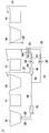
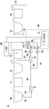
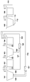
- FIG. 1 is a schematic diagram showing a schematic configuration of an electrodeposition paint recovery system 1 of the present embodiment.
- the electrodeposition paint recovery system 1 of the present embodiment includes an electrodeposition tank 10, a first water washing tank 11, a second water washing tank 12, a third water washing tank 13, 4 rinsing tank 14, fifth rinsing tank 15, first filtration membrane device 16, second filtration membrane device 18, and third filtration membrane device 17.
- the electrodeposition tank 10 is a tank in which an electrodeposition coating of an object to be coated such as a car body, an electric product, and a building material is performed.
- a cationic electrodeposition solution containing an electrodeposition paint made of an epoxy resin and a pigment and the like, a solvent, an organic acid, pure water and the like is accommodated.
- the 1st water washing tank 11, the 2nd water washing tank 12, and the 3rd water washing tank 13 are for performing a membrane filtration filtrate multistage recovery water washing process.
- the first flush tank 11 and the third flush tank 13 are spray-type flush tanks
- the second flush tank 12 is a dip-type flush tank.
- the spray-type washing tank is a type of washing tank that performs washing of an object to be coated by spraying the washing water onto the object to be coated.
- the dip-type washing tank has a larger amount of washing water than the spray-type washing tank, and is a type of washing tank in which the object is washed by completely immersing the object in the washing water. .
- the fourth washing tank 14 and the fifth washing tank 15 are for performing the final washing process.
- the fourth rinsing tank 14 is a dip-type rinsing tank
- the fifth rinsing tank 15 is a spray-type rinsing tank.
- the first filtration membrane device 16 includes an ultrafiltration membrane or a microfiltration membrane (corresponding to the first filtration membrane).
- the ultrafiltration membrane is a filtration membrane having an average pore diameter of about 0.001 ⁇ m to 0.01 ⁇ m
- the microfiltration membrane is a filtration membrane having an average pore diameter of about 0.01 ⁇ m to 10 ⁇ m.
- the average pore diameter of the ultrafiltration membrane and the microfiltration membrane is measured as follows.
- an ultrafiltration membrane or a microfiltration membrane is cut in a cross section perpendicular to the length direction.
- the cross-section is photographed at a magnification that allows the shape of as many pores as possible to be clearly confirmed.
- overlay the transparent sheet on the copy of the electron microscope image paint the pores black using a black pen, etc., and copy the transparent sheet to a blank sheet. Distinguish clearly from white.
- the pore diameter of 100 arbitrarily selected pores is obtained using commercially available image analysis software, and the average pore diameter is calculated by calculating the arithmetic average value.
- image analysis software for example, software “WinRoof” sold by Mitani Corporation can be used.
- the pore diameter refers to a distance connecting an arbitrary point on the circumference of the pore and a point on the circumference of the pore at a position facing the arbitrary point.
- the first filtration membrane device 16 filters the electrodeposition solution in the electrodeposition tank 10, and the electrodeposition solution is supplied from the electrodeposition tank 10 to the first filtration membrane device 16 through the flow path 20.
- the filtered water filtered by the first filtration membrane device 16 is sent to the third washing tank 13 which is the final stage of the membrane filtration filtrate multi-stage recovery water washing process via the flow path 21, and the membrane filtration filtrate multi-stage recovery water washing process. It is used as washing water.
- the concentrated liquid that has not passed through the membrane in the first filtration membrane device 16 is returned to the electrodeposition tank 10 through the flow path 22.
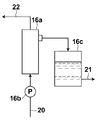
- FIG. 2 is a schematic diagram showing a specific configuration of the first filtration membrane device 16.
- the first filtration membrane device 16 supplies a hollow fiber membrane module 16a having an ultrafiltration membrane or a microfiltration membrane and raw water (electrodeposition solution) to the hollow fiber membrane module 16a.
- a tank 16c in which the filtered water filtered by the hollow fiber membrane module 16a is temporarily stored. The filtered water stored in the tank 16 c is sucked by the pump 35 provided in the flow path 21 and supplied to the flow path 21.
- the third filtration membrane device 17 is also provided with an ultrafiltration membrane or a microfiltration membrane (corresponding to a third filtration membrane).
- the third filtration membrane device 17 filters the washing water in the second washing tank 12, and the washing water is supplied from the second washing tank 12 to the third filtration membrane device 17 through the flow path 23. Supplied. Then, the filtered water filtered by the third filtration membrane device 17 is supplied to the second filtration membrane device 18 connected to the subsequent stage via the flow path 24.
- the third filtration membrane device 17 and the flow path 24 correspond to a supply system.
- the concentrated liquid that has not permeated through the membrane in the third filtration membrane device 17 is provided through the flow path 25 to the first washing tank 11 provided on the electrodeposition tank 10 side with respect to the second washing tank 12. Returned to In the present embodiment, the concentrated liquid of the third filtration membrane device 17 is returned to the first water washing tank 11, but may be returned to the electrodeposition tank 10. Furthermore, in the present embodiment, the flush water in the second flush tank 12 is supplied as filtered water to the third filtration membrane device 17, but flush water other than the second flush tank 12 is supplied. You may make it supply as to-be-filtered water. That is, the flush water in the first flush tank 11 or the flush water in the third flush tank 13 may be supplied to the third filtration membrane device 17.
- the third filtration membrane device 17 is also similar to the configuration of the first filtration membrane device 16 shown in FIG. 2, and includes a hollow fiber membrane module having an ultrafiltration membrane or a microfiltration membrane, and a hollow fiber membrane module. And a tank for temporarily storing the filtered water filtered by the hollow fiber membrane module. The filtered water stored in the tank is sucked by the pump of the third filtration membrane device 17 and supplied to the flow path 24.
- the second filtration membrane device 18 includes a reverse osmosis membrane (corresponding to a second filtration membrane).
- a reverse osmosis membrane (RO (Reverse Osmosis) membrane) is a membrane having an average pore size smaller than that of an NF (Nano filtration) membrane and having a salt rejection rate of 90% or more.
- the second filtration membrane device 18 is supplied with the filtered water of the third filtration membrane device 17 through the flow path 24 as described above.
- the second filtration membrane device 18 is for removing contaminant ions including Na ions from the filtered water of the third filtration membrane device 17.
- the filtered water filtered by the second filtration membrane device 18 is sent to the third washing tank 13 which is the final stage of the membrane filtration filtrate multistage recovery water washing step via the flow path 26, and the membrane filtration filtrate multistage recovery is performed. Used as washing water in the washing step.
- the concentrated liquid that has not permeated the membrane in the second filtration membrane device 18 is returned to the second water rinsing tank 12 via the flow path 27.
- the concentrated solution of the second filtration membrane device 18 is returned to the second washing tank 12, but may be returned to the electrodeposition tank 10 or the first washing tank 11. .
- the second filtration membrane device 18 is the same as the configuration of the first filtration membrane device 16 shown in FIG. 2 except that the type of membrane of the hollow fiber module is a reverse osmosis membrane.
- the object to be coated is mounted on a conveyor (not shown), immersed in the electrodeposition tank 10 and electrodeposited, and then subjected to membrane filtration filtrate multistage recovery.
- the first washing tank 11, the second washing tank 12, and the third washing tank 13 in the washing step are sequentially conveyed to be washed with water.
- the object to be coated is sequentially conveyed to the fourth water rinsing tank 14 and the fifth water rinsing tank 15 in the final water rinsing process, and washed with water.
- the flush water in the membrane filtration filtrate multistage recovery flush process overflows in order from the third flush tank 13 to the second flush tank 12 and the first flush tank 11, and is used as flush water in each flush tank. Furthermore, it overflows from the 1st washing tank 11 to the electrodeposition tank 10, and non-electrodeposition coating material is collect
- Pure water or purified water is supplied from the flow path 40 to the fourth washing tank 14 in the final washing step, and pure water or purified water (engineering water) is supplied to the fifth washing tank 15 as a flow path. Supplied from 41 and cleaned.
- the pure water supplied to the fifth rinsing tank 15 overflows into the fourth rinsing tank 14 and is discharged from the flow path 42 together with the purified water supplied to the fourth rinsing tank 14.
- the electrodeposition paint recovery system 1 is configured to supply the filtered water filtered by the second filtration membrane device 18 to the third rinsing tank 13 in the membrane filtration filtrate multistage recovery water washing step as described above, 1 is provided with a flow rate adjusting unit 30 that adjusts the amount of filtered water filtered by one filtration membrane device 16 to the third washing tank 13.
- the flow rate adjusting unit 30 is connected to the first valve mechanism 31 and the first flow meter 32 provided in the flow path 21 connected to the first filtration membrane device 16 and the second filtration membrane device 18.
- a second valve mechanism 33 and a second flow meter 34 provided in the flow path 26 are provided.
- the first valve mechanism 31 and the first flow meter 32 adjust the supply amount of the filtered water filtered by the first filtration membrane device 16 to the third flush tank 13, and the second valve mechanism 33 and The second flow meter 34 adjusts the supply amount of the filtered water filtered by the second filter membrane device 18 to the third washing tank 13. Adjustment of the supply amount of filtered water may be performed automatically or manually.
- the second water washing tank. 12 has a third filtration membrane device 17 for filtering the water after washing with water, and the filtrate obtained by filtration by the third filtration membrane device 17 is supplied to a second filtration membrane device 18 comprising a reverse osmosis membrane. Is done.
- the filtrate obtained by the filtration by the second filtration membrane device 18 is supplied to the third water washing tank 13 in the final stage.
- the filtrate filtered by the third filtration membrane device 17 in this way is further filtered by the second filtration membrane device 18 made of a reverse osmosis membrane, and the filtrate is supplied to the third washing tank 13 in the final stage. It is possible to increase the final stage washing water and to reduce the non-electrodeposited paint, thereby further improving the paint recovery rate.
- the supply amount of the filtrate filtered by the second filtration membrane device 18 to the third washing tank 13 in the final stage and the third washing tank in the final stage of the filtrate filtered by the first filtration membrane apparatus 16 Since the supply amount to 13 is adjusted, an increase in the Na ion concentration of the electrodeposition solution in the electrodeposition tank can be suppressed, and the quality of the electrodeposition coating can be prevented from being deteriorated.
- a concentrated solution having a high Na ion concentration is returned to the second water rinsing tank 12 by performing filtration through the second filtration membrane device 18 made of a reverse osmosis membrane, whereby Na ion is added to the electrodeposition tank 10.
- the concentration is accumulated, but when the electrodeposition solution containing the accumulated Na ions is filtered by the first filtration membrane device 16, Na ions can be released to the filtrate side, so that the electrodeposition tank 10 An increase in the Na ion concentration of the inner electrodeposition solution can be suppressed.
- the flow rate adjusting unit 30 supplies the supply amount V1 of the filtered water filtered by the first filtration membrane device 16 to the third rinsing tank 13 and the first filtered water filtered by the second filtration membrane device 18.
- Accumulation can be 30 ppm or less, and paint recovery can be 97.2% or more.
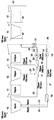
- FIG. 3 is a schematic diagram showing a schematic configuration of the electrodeposition paint recovery system 2 of the present embodiment.
- the third filter membrane device 16 of the electrodeposition paint recovery system 2 of the first embodiment is not provided.
- the filtration membrane device 17 is also used. Since other configurations are the same as those of the electrodeposition paint recovery system 1 of the first embodiment, detailed description thereof is omitted.
- the first filtration membrane device 16 has the same configuration as that of the first embodiment, and includes an ultrafiltration membrane or a microfiltration membrane.
- the first filtration membrane device 16 filters the electrodeposition solution in the electrodeposition tank 10, and the electrodeposition solution is supplied from the electrodeposition tank 10 to the first filtration membrane device 16 through the flow path 20.
- the And the filtered water filtered by the 1st filtration membrane apparatus 16 of this embodiment is passed through the flow path 50 and the flow path 51 to the 3rd washing tank 13 which is the last stage of a membrane filtration filtrate multistage recovery water washing process. Water is supplied and supplied to the second filtration membrane device 18 via the flow path 52.
- the first filtration membrane device 16 and the flow path 52 correspond to a supply system.
- the concentrated liquid that has not permeated the membrane in the first filtration membrane device 16 is returned to the electrodeposition tank 10 via the flow path 22.
- a pump 35 for sucking filtered water stored in the tank of the first filtration membrane device 16 is provided.
- the second filtration membrane device 18 has the same configuration as that of the first embodiment and includes a reverse osmosis membrane. As described above, the second filtration membrane device 18 is supplied with the filtered water of the first filtration membrane device 16 via the flow path 52. The second filtration membrane device 18 is for removing contaminant ions including Na ions from the filtered water of the first filtration membrane device 16. Then, the filtered water filtered by the second filtration membrane device 18 is sent to the third washing tank 13 which is the final stage of the membrane filtration filtrate multistage recovery water washing step via the flow path 26, and the membrane filtration filtrate multistage recovery is performed. Used as washing water in the washing step.
- the concentrated liquid that has not permeated the membrane in the second filtration membrane device 18 is returned to the second water rinsing tank 12 via the flow path 27.
- the concentrated solution of the second filtration membrane device 18 is returned to the second washing tank 12, but may be returned to the electrodeposition tank 10 or the first washing tank 11. .
- the filtered water stored in the tank of the second filtration membrane device 18 is sucked by the pump 36 provided in the flow path 26 and supplied to the flow path 26 as in the first embodiment.
- the electrodeposition paint recovery system 2 of the second embodiment is filtered by the second filtration membrane device 18 in the membrane filtration filtrate multistage recovery water washing step, similarly to the electrodeposition paint recovery system 1 of the first embodiment.
- a flow rate adjusting unit 30 that adjusts the supply amount of the filtered water to the third washing tank 13 and the supply amount of the filtered water filtered by the first filtration membrane device 16 to the third washing tank 13. I have.
- the configuration of the flow rate adjusting unit 30 is the same as that of the first embodiment.
- the first filter membrane is used. It has the 2nd filtration membrane apparatus 18 which consists of a reverse osmosis membrane which filters the filtrate of the apparatus 16.
- the filtrate obtained by the filtration by the second filtration membrane device 18 is supplied to the third water washing tank 13 in the final stage.
- the filtrate filtered by the first filtration membrane device 16 in this way is further filtered by the second filtration membrane device 18 made of a reverse osmosis membrane, and the filtrate is supplied to the third water washing tank 13 in the final stage. It is possible to increase the final stage washing water and reduce the amount of non-electrodeposited paint, thereby further improving the paint recovery rate.
- the supply amount of the filtrate filtered by the second filtration membrane device 18 to the third washing tank 13 in the final stage and the third washing tank in the final stage of the filtrate filtered by the first filtration membrane apparatus 16 Since the supply amount to 13 is adjusted, an increase in the Na ion concentration of the electrodeposition solution in the electrodeposition tank can be suppressed, and the quality of the electrodeposition coating can be maintained.
- a concentrated solution having a high Na ion concentration is returned to the second water rinsing tank 12 by performing filtration through the second filtration membrane device 18 made of a reverse osmosis membrane, whereby Na ion is added to the electrodeposition tank 10.
- the concentration is accumulated, but when the electrodeposition solution containing the accumulated Na ions is filtered by the first filtration membrane device 16, Na ions can be released to the filtrate side, so that the electrodeposition tank 10 An increase in the Na ion concentration of the inner electrodeposition solution can be suppressed.
- the flow rate adjusting unit 30 supplies the filtrate V1 to the third rinsing tank 13 of the first filtration membrane device 16 and the second filtration membrane device.
- the Na ion concentration of the rinsing water in the first rinsing tank 11 was adjusted to 30 ppm or less by adjusting the ratio with the supply amount V2 of the 18 filtered water to the third rinsing tank 13.
- the ion concentration is measured, and based on the measured value, the supply amount V1 of the filtered water of the first filtration membrane device 16 to the third washing tank 13 and the third of the filtered water of the second filtration membrane device 18 are measured.
- FIG. 4 is a diagram showing a schematic configuration when the supply amount V1 and the supply amount V2 are automatically adjusted in the electrodeposition paint recovery system 2 of the second embodiment.
- the first A flow rate control unit 37 that controls the valve mechanism 31 and the second valve mechanism 33 may be provided.
- the measurement unit 60 measures the electrical conductivity of the flush water in the third flush tank 13 and does not directly measure the Na ion concentration. Since there is a correlation, the Na ion concentration can be indirectly measured by measuring the electrical conductivity.
- the flow rate control unit 37 automatically adjusts the supply amount V1 and the supply amount V2 by controlling the first valve mechanism 31 and the second valve mechanism 33 as described above. Specifically, the flow rate control unit 37 automatically adjusts the supply amount V1 and the supply amount V2 in accordance with the amount of change in electrical conductivity measured by the measurement unit 60, so that The Na ion concentration of the rinsing water is kept within a predetermined threshold range, thereby maintaining the Na ion concentration of the electrodeposition solution in the electrodeposition tank 10 at 30 ppm or less. In addition, what is necessary is just to obtain
- the measurement unit 60 and the flow rate control unit 37 are provided for the electrodeposition paint recovery system 2 of the second embodiment, but the electrodeposition paint recovery system 1 of the first embodiment is provided.
- the measuring unit 60 and the flow rate control unit 37 may be provided.
- a reverse osmosis membrane is used as the filtration membrane of the second filtration membrane device 18.
- this reverse osmosis membrane has a positive zeta potential. It is preferable to use it.
- resin components contained in the filtrate of the third filtration membrane device 17 of the first embodiment or the first filtration membrane device 16 of the second embodiment, etc. Can be prevented from adhering to the reverse osmosis membrane.
- a cationic paint having a pH (potential hydrogen) of 5.0 to 6.0 is used as an electrodeposition paint
- the reverse osmosis has a positive zeta potential when the pH is 5.0 to 6.0.
- the zeta potential can be measured by a zeta potential measuring device (Anton-Paar, EKA (Electro-Kinetic Analyzer)). Specifically, the zeta potential is measured by first cutting a hollow fiber of a reverse osmosis membrane into an appropriate length and packing it into a cylindrical cell having a diameter of 20 mm and a length of 50 mm. And it can measure by setting an electrode at the both ends of the cell, filling the inside of the cell with a potassium chloride solution, and applying an electric field to the cell with a zeta potential measuring device.
- a zeta potential measuring device Anton-Paar, EKA (Electro-Kinetic Analyzer)
- the present invention is not limited to the above-described embodiment, and may be modified without changing the gist described in each claim.
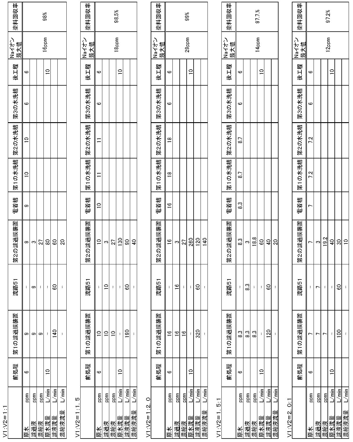
- Table 1 shows the supply amount V1 of the filtered water filtered by the first filtration membrane device 16 to the third washing tank 13 and the third washing tank of the filtered water filtered by the second filtration membrane device 18.
- V1: V2 1: 1
- V1: V2 1: 1.5
- V1: V2 1: 2.0
- KCV3010 (made by Asahi Kasei Co., Ltd.) is used as the hollow fiber module of the first filtration membrane device 16 and the third filtration membrane device 17, and RE4040BLF (made by Eunjin Chemical Co., Ltd.) as the hollow fiber module of the second filtration membrane device 18.
- RE4040BLF (made by Eunjin Chemical Co., Ltd.)
- the Na ion concentration of the washing water in the 2nd washing tank 12 and the Na ion concentration in the 3rd washing tank 13 are shown.
- the first to third lines except for the title line of each table in Table 1 show the Na ion concentration (ppm), and the fourth to sixth lines are the raw water, filtrate and concentrated liquid.
- the flow rate (L / min) is shown.
- the Na ion concentration shown in Table 1 is an average value of Na ion concentrations after each cleaning when a plurality of objects to be coated are washed a plurality of times at the flow rates shown in Table 1.
- the “pretreatment” shown in Table 1 is a treatment that is performed on an object to be coated before the object to be coated is put into the electrodeposition tank 10.
- NaOH or Na salt added as a degreasing agent in the degreasing process mentioned above adheres to a to-be-coated object, and is carried in the electrodeposition tank 10.
- the “raw water flow rate” and the “raw water” Na ion concentration in “Pretreatment” shown in Table 1 adhere to the object to be coated when the object to be coated is put into the electrodeposition tank 10 and are in the electrodeposition tank 10.
- the average value of the flow rate of the liquid adhering to the object to be coated and brought into the electrodeposition tank 10 is 10 L / min
- the average value of the Na ion concentration is 6 ppm
- the Na ion concentration The maximum value of was 10 ppm.
- the average value of the Na ion concentration of the liquid adhering to the object to be coated and brought into the electrodeposition bath 10 is not more than the Na ion concentration of the electrodeposition solution in the electrodeposition bath 10.
- the flow rate and Na ion concentration in the “final cleaning step” shown in Table 1 are the same as those in the case where the object to be coated is introduced from the third water washing tank 13 to the fourth water washing tank 14 in the final washing step. It is the average value of the flow rate of the washing water brought into the washing tank 14 together with the object to be coated and the Na ion concentration. In the examples shown in Table 1, the average value of the flow rate of the washing water brought into the final cleaning process was 10 L / min, and the average value of the Na ion concentration was 6 ppm.
- the electrodeposition solution containing the paint and the pigment or the washing water was centrifuged, and the supernatant was used as a sample. Centrifugation was performed at 15000 rpm for 20 minutes. Further, the washing water containing no pigment was used as a sample without using centrifugation. The sample was placed in a 20 cc polyethylene bottle and diluted with pure water so that it entered the calibration curve of the Na ion standard solution.
- the concentration of Na ion was measured using ICP (Inductively Coupled Plasma) (inductively coupled plasma) emission spectroscopy.
- ICP Inductively Coupled Plasma
- Optima 5300 DV made by Perkin Elmer was used. The measurement wavelength was 589.592 nm, the output was 1300 kW, the feed gas was argon gas, and the plasma observation direction was the radial direction.
- the test solution was measured, and when the Na ion concentration was equal to or higher than the calibration curve, it was diluted to fall within the calibration curve and remeasured.
- NV Non-Volatile
- Paint recovery rate ⁇ 1- (NV of third washing tank 13 / NV of electrodeposition tank 10) ⁇ ⁇ 100
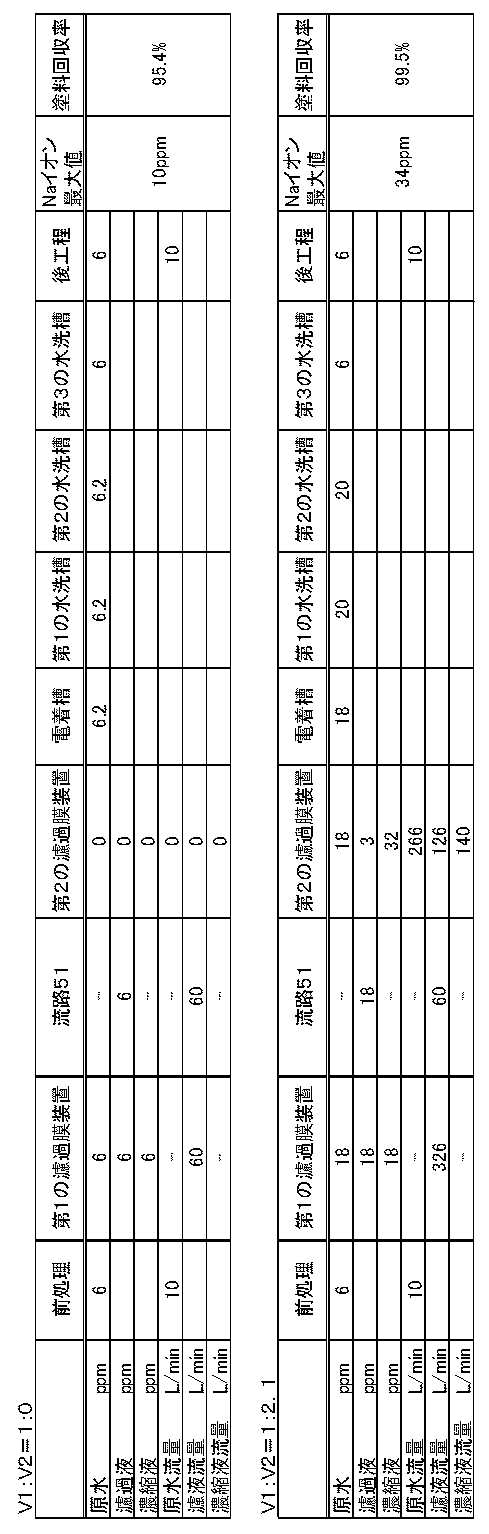
- the meaning of Na ion concentration of “raw water flow rate” and “raw water” in “pretreatment” and “final cleaning process” shown in Table 2 is the same as that in the above-described embodiment.
- the measuring method of Na ion concentration and NV is the same as that of an Example.
- the maximum value of the Na ion concentration of the rinsing water in the first rinsing tank 11 was 34 ppm. That is, it was found that the Na ion concentration in the electrodeposition tank 10 exceeded 30 ppm when cleaning was continued. However, the paint recovery rate was 99.5%.
- Table 3 shows the supply amount V1 of the filtered water filtered by the first filtration membrane device 16 to the third washing tank 13, and the third washing tank of the filtered water filtered by the second filtration membrane device 18.
- KCV3010 (Asahi Kasei Co., Ltd.) was used as the hollow fiber module of the first filtration membrane device 16
- RE4040BLF (Eunjin Chemical Co., Ltd.) was used as the hollow fiber module of the second filtration membrane device 18.
- the Na ion concentration shown in Table 3 is the average value of the Na ion concentration after each cleaning when a plurality of objects to be coated are cleaned at the flow rate shown in Table 1, as in the first embodiment.
- the meanings of the flow rate and Na ion concentration of “pretreatment” and “final cleaning step” shown in Table 3 are the same as those in the example of the first embodiment.
- the measurement method of Na ion concentration and NV is also the same as that of the Example of 1st Embodiment.
- the Na ion concentration of the washing water in the first washing tank 11 was the highest, and the average value of the Na ion concentration was 10 ppm. Further, even when the Na ion concentration of the chemical conversion solution brought in from the pretreatment was 10 ppm at the maximum value, the maximum value of the Na ion concentration of the rinsing water in the first rinsing tank 11 was 16 ppm. That is, the Na ion concentration in the electrodeposition tank 10 could be maintained at 30 ppm or less.
- the meanings of the flow rate and Na ion concentration of “pretreatment” and “final cleaning step” shown in Table 4 are the same as those in the above-described embodiment.
- the measuring method of Na ion concentration and NV is the same as that of an Example.
- the maximum value of the Na ion concentration of the rinsing water in the first rinsing tank 11 was 34 ppm. That is, it was found that the Na ion concentration in the electrodeposition tank 10 exceeded 30 ppm when cleaning was continued. However, the paint recovery rate was 99.5%.
Landscapes
- Chemical & Material Sciences (AREA)
- Engineering & Computer Science (AREA)
- Organic Chemistry (AREA)
- Chemical Kinetics & Catalysis (AREA)
- Electrochemistry (AREA)
- Life Sciences & Earth Sciences (AREA)
- Materials Engineering (AREA)
- Metallurgy (AREA)
- Health & Medical Sciences (AREA)
- Analytical Chemistry (AREA)
- Physics & Mathematics (AREA)
- Biochemistry (AREA)
- General Health & Medical Sciences (AREA)
- General Physics & Mathematics (AREA)
- Immunology (AREA)
- Pathology (AREA)
- Hydrology & Water Resources (AREA)
- Environmental & Geological Engineering (AREA)
- Water Supply & Treatment (AREA)
- Food Science & Technology (AREA)
- Medicinal Chemistry (AREA)
- Separation Using Semi-Permeable Membranes (AREA)
Abstract
Description

塗料回収率={1-(第3の水洗槽13のNV/電着槽10のNV)}×100

Claims (16)
- 被塗装物の電着塗装が行われる電着槽と、
電着塗装後の被塗装物の水洗が段階的に行われる少なくとも2つの水洗槽と、
限外濾過膜または精密濾過膜からなり、前記電着槽内の電着塗料を含む電着溶液の濾過により得られた濾液と濃縮液とをそれぞれ、最終段の前記水洗槽と前記電着槽とに供給する第1の濾過膜と、
前記電着槽内の前記電着溶液および前記水洗槽内の水洗後の水のいずれか一方を限外濾過または精密濾過した濾過水を供給する供給系と、
逆浸透膜からなり、前記供給系から供給される前記濾過水の濾過により得られた濾液と濃縮液とをそれぞれ、前記最終段の水洗槽と前記電着槽および前記最終段の水洗槽以外の水洗槽の何れかとに供給する第2の濾過膜と、
前記第1の濾過膜によって濾過された濾液および前記第2の濾過膜によって濾過された濾液の前記最終段の水洗槽への供給量をそれぞれ調整する流量調整部とを備え、
前記最終段の水洗槽から水洗後の水が前記電着槽側の水洗槽および前記電着槽に順に供給されることを特徴とする電着塗料回収システム。 - 前記供給系は、限外濾過膜又は精密濾過膜からなり、前記少なくとも2つの水洗槽のいずれかの水洗漕内の水洗後の水の濾過により得られた濾液と濃縮液とをそれぞれ、前記供給系を介して前記第2の濾過膜と前記最終段の水洗槽よりも前記電着槽側の水洗槽に供給する第3の濾過膜を有することを特徴とする請求項1記載の電着塗料回収システム。
- 前記第1の濾過膜は、前記電着溶液の濾過により得られた濾液を、前記供給系を介して前記第2の濾過膜にも供給することを特徴とする請求項1記載の電着塗料回収システム。
- 前記流量調整部が、前記第1の濾過膜によって濾過された濾液の前記最終段の水洗槽への供給量V1と前記第2の濾過膜によって濾過された濾液の前記最終段の水洗槽への供給量V2との比V1:V2が、1:2~2:1となるように調整する請求項1から3いずれか1項記載の電着塗料回収システム。
- 前記流量調整部が、前記V1:V2が1:1となるように調整する請求項4記載の電着塗料回収システム。
- 前記流量調整部が、前記電着槽に最も近い前記水洗槽の水洗後の水のNaイオン濃度が30ppm以下となるように、前記第1の濾過膜によって濾過された濾液の前記最終段の水洗槽への供給量および前記第2の濾過膜によって濾過された濾液の前記最終段の水洗槽への供給量を調整する請求項1から5いずれか1項記載の電着塗料回収システム。
- 前記最終段の水洗槽内の水洗後の水の電気伝導度を計測する計測部を備え、
前記流量調整部が、前記計測部によって計測された電気伝導度に基づいて、前記第1の濾過膜によって濾過された濾液の前記最終段の水洗槽への供給量および前記第2の濾過膜によって濾過された濾液の前記最終段の水洗槽への供給量を自動的に調整する請求項6記載の電着塗料回収システム。 - 前記第2の濾過膜が、ゼータ電位が正である濾過膜である請求項1から7いずれか1項記載の電着塗料回収システム。
- 被塗装物の電着塗装が行われる電着槽と、電着塗装後の被塗装物の水洗が段階的に行われる少なくとも2つの水洗槽と、限外濾過膜または精密濾過膜からなり、前記電着槽内の電着塗料を含む電着溶液の濾過により得られた濾液と濃縮液とをそれぞれ、最終段の前記水洗槽と前記電着槽とに供給する第1の濾過膜とを用い、前記最終段の水洗槽から水洗後の水が前記電着槽側の水洗槽および前記電着槽に順に供給される電着塗料回収方法であって、
前記電着槽内の前記電着溶液および前記水洗槽内の水洗後の水のいずれか一方を限外濾過または精密濾過した濾過水を、逆浸透膜からなる第2の濾過膜によって濾過し、
該濾過によって得られた濾液と濃縮液とをそれぞれ、前記最終段の水洗槽と前記電着槽および前記最終段の水洗槽以外の水洗槽の何れかに供給し、
前記第1の濾過膜によって濾過された濾液および前記第2の濾過膜によって濾過された濾液の前記最終段の水洗槽への供給量をそれぞれ調整することを特徴とする電着塗料回収方法。 - 限外濾過膜又は精密濾過膜からなる第3の濾過膜を用い、前記少なくとも2つの水洗槽のいずれかの水洗漕内の水洗後の水を濾過し、該濾過により得られた濾液と濃縮液とをそれぞれ、前記第2の濾過膜と前記最終段の水洗槽よりも前記電着槽側の水洗槽に供給することを特徴とする請求項9記載の電着塗料回収方法。
- 前記第1の濾過膜は、前記電着溶液の濾過により得られた濾液を前記第2の濾過膜にも供給することを特徴とする請求項9記載の電着塗料回収方法。
- 前記第1の濾過膜によって濾過された濾液の前記最終段の水洗槽への供給量V1と前記第2の濾過膜によって濾過された濾液の前記最終段の水洗槽への供給量V2との比V1:V2が、1:2~2:1となるように調整する請求項9から11いずれか1項記載の電着塗料回収方法。
- 前記V1:V2が1:1となるように調整する請求項12記載の電着塗料回収方法。
- 前記電着槽に最も近い前記水洗槽の水洗後の水のNaイオン濃度が30ppm以下となるように、前記第1の濾過膜によって濾過された濾液の前記最終段の水洗槽への供給量および前記第2の濾過膜によって濾過された濾液の前記最終段の水洗槽への供給量を調整する請求項9から13いずれか1項記載の電着塗料回収方法。
- 前記最終段の水洗槽内の水洗後の水の電気伝導度を計測し、
該計測した電気伝導度に基づいて、前記第1の濾過膜によって濾過された濾液の前記最終段の水洗槽への供給量および前記第2の濾過膜によって濾過された濾液の前記最終段の水洗槽への供給量を自動的に調整する請求項14記載の電着塗料回収方法。 - 前記第2の濾過膜が、ゼータ電位が正である濾過膜である請求項9から15いずれか1項記載の電着塗料回収方法。
Priority Applications (5)
| Application Number | Priority Date | Filing Date | Title |
|---|---|---|---|
| KR1020177017542A KR20170088958A (ko) | 2014-12-26 | 2015-12-25 | 전착 도료 회수 시스템 및 방법 |
| JP2016554507A JP6145909B2 (ja) | 2014-12-26 | 2015-12-25 | 電着塗料回収システムおよび方法 |
| CN201580070677.5A CN107109680B (zh) | 2014-12-26 | 2015-12-25 | 电沉积涂料回收系统及方法 |
| US15/538,068 US10718061B2 (en) | 2014-12-26 | 2015-12-25 | Electrodeposition paint recovery system and method |
| MX2017008409A MX2017008409A (es) | 2014-12-26 | 2015-12-25 | Sistema y metodo de recuperacion de pintura por electrodeposicion. |
Applications Claiming Priority (4)
| Application Number | Priority Date | Filing Date | Title |
|---|---|---|---|
| JP2014265507 | 2014-12-26 | ||
| JP2014-265507 | 2014-12-26 | ||
| JP2015130880 | 2015-06-30 | ||
| JP2015-130880 | 2015-06-30 |
Publications (1)
| Publication Number | Publication Date |
|---|---|
| WO2016103732A1 true WO2016103732A1 (ja) | 2016-06-30 |
Family
ID=56149789
Family Applications (1)
| Application Number | Title | Priority Date | Filing Date |
|---|---|---|---|
| PCT/JP2015/006485 Ceased WO2016103732A1 (ja) | 2014-12-26 | 2015-12-25 | 電着塗料回収システムおよび方法 |
Country Status (6)
| Country | Link |
|---|---|
| US (1) | US10718061B2 (ja) |
| JP (2) | JP6145909B2 (ja) |
| KR (1) | KR20170088958A (ja) |
| CN (1) | CN107109680B (ja) |
| MX (1) | MX2017008409A (ja) |
| WO (1) | WO2016103732A1 (ja) |
Cited By (3)
| Publication number | Priority date | Publication date | Assignee | Title |
|---|---|---|---|---|
| JP2018172711A (ja) * | 2017-03-31 | 2018-11-08 | マツダ株式会社 | 電着塗装方法 |
| JP2018172712A (ja) * | 2017-03-31 | 2018-11-08 | マツダ株式会社 | 電着塗装方法 |
| WO2025078107A1 (en) * | 2023-10-12 | 2025-04-17 | Basf Coatings Gmbh | Cathodic electrodeposition process |
Families Citing this family (4)
| Publication number | Priority date | Publication date | Assignee | Title |
|---|---|---|---|---|
| KR101910853B1 (ko) * | 2017-04-20 | 2018-10-24 | (주)진합 | 도금 공정의 폐수 저감형 수세장치 |
| JP2019007074A (ja) * | 2017-06-22 | 2019-01-17 | アイシン精機株式会社 | 電着塗装装置 |
| JP6779245B2 (ja) * | 2018-02-26 | 2020-11-04 | 株式会社大気社 | 電着塗装設備 |
| CN113293422B (zh) * | 2021-05-08 | 2022-02-22 | 临澧金华天机械制造有限公司 | 一种标准节的自动化涂装设备 |
Citations (6)
| Publication number | Priority date | Publication date | Assignee | Title |
|---|---|---|---|---|
| JPS54100965U (ja) * | 1978-12-13 | 1979-07-16 | ||
| JPS62177196A (ja) * | 1986-01-29 | 1987-08-04 | Mitsubishi Electric Corp | 逆浸透装置による電着塗装の洗浄方法 |
| JPH07224397A (ja) * | 1994-02-14 | 1995-08-22 | Shinto Paint Co Ltd | 電着塗装における回収水洗方法 |
| JP2003105594A (ja) * | 2001-09-27 | 2003-04-09 | Nippon Paint Co Ltd | クローズドシステム電着塗装装置および電着塗装方法 |
| JP2004149899A (ja) * | 2002-10-31 | 2004-05-27 | Yuasa Corp | 電着塗料の回収方法 |
| JP2011099158A (ja) * | 2009-11-09 | 2011-05-19 | Asahi Kasei Chemicals Corp | 電着塗料の回収システム |
Family Cites Families (5)
| Publication number | Priority date | Publication date | Assignee | Title |
|---|---|---|---|---|
| JPS54100965A (en) | 1978-01-27 | 1979-08-09 | Nippon Steel Corp | Manufacture of welded large diameter steel tube for heat treatment |
| WO1996007775A1 (en) * | 1994-09-06 | 1996-03-14 | Nippon Paint Co., Ltd. | Method of treating waste liquor from final water washing tank used in cation electrodeposition painting |
| DE60129700T3 (de) * | 2000-06-30 | 2012-03-15 | Asahi Kasei Chemicals Corp. | Verfahren und vorrichtung zur behandlung von abwasser kationischer elektroabscheidungsüberzugs-beschichtungsverfahren |
| JP2004149889A (ja) * | 2002-10-31 | 2004-05-27 | Jfe Steel Kk | プレス成形性および耐食性に優れた表面処理金属板 |
| US20120024325A1 (en) | 2009-01-29 | 2012-02-02 | Asahi Kasei Chemicals Corporation | System for recovery of electrodeposition paint |
-
2015
- 2015-12-25 MX MX2017008409A patent/MX2017008409A/es unknown
- 2015-12-25 KR KR1020177017542A patent/KR20170088958A/ko not_active Ceased
- 2015-12-25 CN CN201580070677.5A patent/CN107109680B/zh active Active
- 2015-12-25 WO PCT/JP2015/006485 patent/WO2016103732A1/ja not_active Ceased
- 2015-12-25 JP JP2016554507A patent/JP6145909B2/ja active Active
- 2015-12-25 US US15/538,068 patent/US10718061B2/en active Active
-
2016
- 2016-09-09 JP JP2016176395A patent/JP2017014626A/ja active Pending
Patent Citations (6)
| Publication number | Priority date | Publication date | Assignee | Title |
|---|---|---|---|---|
| JPS54100965U (ja) * | 1978-12-13 | 1979-07-16 | ||
| JPS62177196A (ja) * | 1986-01-29 | 1987-08-04 | Mitsubishi Electric Corp | 逆浸透装置による電着塗装の洗浄方法 |
| JPH07224397A (ja) * | 1994-02-14 | 1995-08-22 | Shinto Paint Co Ltd | 電着塗装における回収水洗方法 |
| JP2003105594A (ja) * | 2001-09-27 | 2003-04-09 | Nippon Paint Co Ltd | クローズドシステム電着塗装装置および電着塗装方法 |
| JP2004149899A (ja) * | 2002-10-31 | 2004-05-27 | Yuasa Corp | 電着塗料の回収方法 |
| JP2011099158A (ja) * | 2009-11-09 | 2011-05-19 | Asahi Kasei Chemicals Corp | 電着塗料の回収システム |
Cited By (3)
| Publication number | Priority date | Publication date | Assignee | Title |
|---|---|---|---|---|
| JP2018172711A (ja) * | 2017-03-31 | 2018-11-08 | マツダ株式会社 | 電着塗装方法 |
| JP2018172712A (ja) * | 2017-03-31 | 2018-11-08 | マツダ株式会社 | 電着塗装方法 |
| WO2025078107A1 (en) * | 2023-10-12 | 2025-04-17 | Basf Coatings Gmbh | Cathodic electrodeposition process |
Also Published As
| Publication number | Publication date |
|---|---|
| KR20170088958A (ko) | 2017-08-02 |
| US20170342588A1 (en) | 2017-11-30 |
| JPWO2016103732A1 (ja) | 2017-04-27 |
| US10718061B2 (en) | 2020-07-21 |
| JP2017014626A (ja) | 2017-01-19 |
| JP6145909B2 (ja) | 2017-06-14 |
| CN107109680A (zh) | 2017-08-29 |
| MX2017008409A (es) | 2017-10-19 |
| CN107109680B (zh) | 2019-04-26 |
Similar Documents
| Publication | Publication Date | Title |
|---|---|---|
| JP6145909B2 (ja) | 電着塗料回収システムおよび方法 | |
| CN109761386A (zh) | 水性漆清洗废溶剂处理装置 | |
| CN1184350C (zh) | 回收磷酸盐化学转化中的水性洗液方法和用于金属表面处理的装置 | |
| CN1116448C (zh) | 阳离子电沉积积涂漆中最终水洗槽废液的处理方法 | |
| CN106495379B (zh) | 一种电镀漂洗水循环回用及重金属回收工艺 | |
| CN111556852A (zh) | 部件的再生方法以及海水淡化方法 | |
| KR101321228B1 (ko) | 전착 도료 회수 시스템 및 전착 도료 회수 장치 | |
| DE102012218495A1 (de) | Verfahren und Vorrichtung zur kathodischen Tauchlackierung | |
| JP4751419B2 (ja) | 電着塗装の水洗システム | |
| JP2003105594A (ja) | クローズドシステム電着塗装装置および電着塗装方法 | |
| JP7113915B1 (ja) | 塗装設備の排水リサイクルシステム | |
| JP2011099158A (ja) | 電着塗料の回収システム | |
| JP2002235196A (ja) | 電着塗装システム | |
| WO2019163251A1 (ja) | 電着塗装設備 | |
| KR101469844B1 (ko) | 아노다이징 공정의 청정생산 시스템 개발 | |
| CN103435174A (zh) | 一种电镀含镍废水的处理系统及工艺 | |
| JP2002212790A (ja) | 電着塗装方法 | |
| JP2008024965A (ja) | 電着塗装における被塗物の水洗方法および装置 | |
| CN103435173A (zh) | 一种用于处理电镀酸铜废水的处理系统及工艺 | |
| CN105624651A (zh) | 一种针对连续式化学镀的清洗方法 | |
| JP4630157B2 (ja) | 化成処理における化成処理液成分の回収方法 | |
| Macko et al. | Wastewater from processing: Microfiltration in metal finishing plants | |
| JP2008194698A (ja) | 分離膜モジュールの洗浄方法 | |
| JP2007050361A (ja) | 非イオン性有機物の回収方法 | |
| CN106348516A (zh) | 电镀废水的回收处理方法处理系统和应用 |
Legal Events
| Date | Code | Title | Description |
|---|---|---|---|
| 121 | Ep: the epo has been informed by wipo that ep was designated in this application |
Ref document number: 15872303 Country of ref document: EP Kind code of ref document: A1 |
|
| ENP | Entry into the national phase |
Ref document number: 2016554507 Country of ref document: JP Kind code of ref document: A |
|
| WWE | Wipo information: entry into national phase |
Ref document number: 15538068 Country of ref document: US |
|
| WWE | Wipo information: entry into national phase |
Ref document number: MX/A/2017/008409 Country of ref document: MX |
|
| ENP | Entry into the national phase |
Ref document number: 20177017542 Country of ref document: KR Kind code of ref document: A |
|
| NENP | Non-entry into the national phase |
Ref country code: DE |
|
| 122 | Ep: pct application non-entry in european phase |
Ref document number: 15872303 Country of ref document: EP Kind code of ref document: A1 |