WO2016103698A1 - レンズ駆動装置、カメラモジュール、及びカメラ搭載装置 - Google Patents
レンズ駆動装置、カメラモジュール、及びカメラ搭載装置 Download PDFInfo
- Publication number
- WO2016103698A1 WO2016103698A1 PCT/JP2015/006424 JP2015006424W WO2016103698A1 WO 2016103698 A1 WO2016103698 A1 WO 2016103698A1 JP 2015006424 W JP2015006424 W JP 2015006424W WO 2016103698 A1 WO2016103698 A1 WO 2016103698A1
- Authority
- WO
- WIPO (PCT)
- Prior art keywords
- autofocus
- unit
- lens
- driving device
- coil
- Prior art date
- Legal status (The legal status is an assumption and is not a legal conclusion. Google has not performed a legal analysis and makes no representation as to the accuracy of the status listed.)
- Ceased
Links
Images





Classifications
-
- G—PHYSICS
- G02—OPTICS
- G02B—OPTICAL ELEMENTS, SYSTEMS OR APPARATUS
- G02B7/00—Mountings, adjusting means, or light-tight connections, for optical elements
- G02B7/02—Mountings, adjusting means, or light-tight connections, for optical elements for lenses
- G02B7/04—Mountings, adjusting means, or light-tight connections, for optical elements for lenses with mechanism for focusing or varying magnification
- G02B7/08—Mountings, adjusting means, or light-tight connections, for optical elements for lenses with mechanism for focusing or varying magnification adapted to co-operate with a remote control mechanism
-
- G—PHYSICS
- G02—OPTICS
- G02B—OPTICAL ELEMENTS, SYSTEMS OR APPARATUS
- G02B7/00—Mountings, adjusting means, or light-tight connections, for optical elements
- G02B7/02—Mountings, adjusting means, or light-tight connections, for optical elements for lenses
- G02B7/04—Mountings, adjusting means, or light-tight connections, for optical elements for lenses with mechanism for focusing or varying magnification
- G02B7/10—Mountings, adjusting means, or light-tight connections, for optical elements for lenses with mechanism for focusing or varying magnification by relative axial movement of several lenses, e.g. of varifocal objective lens
- G02B7/102—Mountings, adjusting means, or light-tight connections, for optical elements for lenses with mechanism for focusing or varying magnification by relative axial movement of several lenses, e.g. of varifocal objective lens controlled by a microcomputer
-
- G—PHYSICS
- G02—OPTICS
- G02B—OPTICAL ELEMENTS, SYSTEMS OR APPARATUS
- G02B26/00—Optical devices or arrangements for the control of light using movable or deformable optical elements
- G02B26/08—Optical devices or arrangements for the control of light using movable or deformable optical elements for controlling the direction of light
- G02B26/0816—Optical devices or arrangements for the control of light using movable or deformable optical elements for controlling the direction of light by means of one or more reflecting elements
- G02B26/0833—Optical devices or arrangements for the control of light using movable or deformable optical elements for controlling the direction of light by means of one or more reflecting elements the reflecting element being a micromechanical device, e.g. a MEMS mirror, DMD
- G02B26/085—Optical devices or arrangements for the control of light using movable or deformable optical elements for controlling the direction of light by means of one or more reflecting elements the reflecting element being a micromechanical device, e.g. a MEMS mirror, DMD the reflecting means being moved or deformed by electromagnetic means
-
- G—PHYSICS
- G01—MEASURING; TESTING
- G01J—MEASUREMENT OF INTENSITY, VELOCITY, SPECTRAL CONTENT, POLARISATION, PHASE OR PULSE CHARACTERISTICS OF INFRARED, VISIBLE OR ULTRAVIOLET LIGHT; COLORIMETRY; RADIATION PYROMETRY
- G01J1/00—Photometry, e.g. photographic exposure meter
- G01J1/02—Details
- G01J1/04—Optical or mechanical part supplementary adjustable parts
- G01J1/0407—Optical elements not provided otherwise, e.g. manifolds, windows, holograms, gratings
- G01J1/0414—Optical elements not provided otherwise, e.g. manifolds, windows, holograms, gratings using plane or convex mirrors, parallel phase plates, or plane beam-splitters
-
- G—PHYSICS
- G02—OPTICS
- G02B—OPTICAL ELEMENTS, SYSTEMS OR APPARATUS
- G02B7/00—Mountings, adjusting means, or light-tight connections, for optical elements
- G02B7/02—Mountings, adjusting means, or light-tight connections, for optical elements for lenses
- G02B7/04—Mountings, adjusting means, or light-tight connections, for optical elements for lenses with mechanism for focusing or varying magnification
- G02B7/09—Mountings, adjusting means, or light-tight connections, for optical elements for lenses with mechanism for focusing or varying magnification adapted for automatic focusing or varying magnification
-
- G—PHYSICS
- G02—OPTICS
- G02B—OPTICAL ELEMENTS, SYSTEMS OR APPARATUS
- G02B7/00—Mountings, adjusting means, or light-tight connections, for optical elements
- G02B7/28—Systems for automatic generation of focusing signals
-
- H—ELECTRICITY
- H04—ELECTRIC COMMUNICATION TECHNIQUE
- H04N—PICTORIAL COMMUNICATION, e.g. TELEVISION
- H04N23/00—Cameras or camera modules comprising electronic image sensors; Control thereof
- H04N23/50—Constructional details
- H04N23/54—Mounting of pick-up tubes, electronic image sensors, deviation or focusing coils
-
- H—ELECTRICITY
- H04—ELECTRIC COMMUNICATION TECHNIQUE
- H04N—PICTORIAL COMMUNICATION, e.g. TELEVISION
- H04N23/00—Cameras or camera modules comprising electronic image sensors; Control thereof
- H04N23/50—Constructional details
- H04N23/55—Optical parts specially adapted for electronic image sensors; Mounting thereof
-
- H—ELECTRICITY
- H04—ELECTRIC COMMUNICATION TECHNIQUE
- H04N—PICTORIAL COMMUNICATION, e.g. TELEVISION
- H04N23/00—Cameras or camera modules comprising electronic image sensors; Control thereof
- H04N23/56—Cameras or camera modules comprising electronic image sensors; Control thereof provided with illuminating means
-
- H—ELECTRICITY
- H04—ELECTRIC COMMUNICATION TECHNIQUE
- H04N—PICTORIAL COMMUNICATION, e.g. TELEVISION
- H04N23/00—Cameras or camera modules comprising electronic image sensors; Control thereof
- H04N23/57—Mechanical or electrical details of cameras or camera modules specially adapted for being embedded in other devices
-
- H—ELECTRICITY
- H04—ELECTRIC COMMUNICATION TECHNIQUE
- H04N—PICTORIAL COMMUNICATION, e.g. TELEVISION
- H04N23/00—Cameras or camera modules comprising electronic image sensors; Control thereof
- H04N23/60—Control of cameras or camera modules
Definitions
- the present invention relates to a lens driving device for autofocus, a camera module having an autofocus function, and a camera mounting device.
- a small camera module is mounted on a mobile terminal such as a smartphone.
- a lens driving device having an autofocus function hereinafter referred to as “AF function”, AF: Auto ⁇ Focus) that automatically performs focusing when photographing a subject is applied to such a camera module.
- the autofocus lens drive device includes an autofocus drive unit (hereinafter referred to as “AF drive unit”) for moving the lens unit in the optical axis direction.
- the AF drive unit includes, for example, an autofocus coil unit (hereinafter referred to as “AF coil unit”) disposed around the lens unit, and an auto unit disposed in a radial direction away from the AF coil unit.
- AF magnet section a focusing magnet section (hereinafter referred to as “AF magnet section”).
- AF fixing unit an autofocus fixing unit including the AF magnet unit.
- AF fixing unit an autofocus movable part including the AF coil part is moved in the optical axis direction, thereby automatically focusing.
- the reflective photoreflector has a light emitting part and a light receiving part in one semiconductor package, reflects light (for example, infrared rays) emitted from the light emitting part by an object to be detected, and intensity of reflected light incident on the light receiving part. It is an optical sensor that detects the position of the detection target from When detecting the position of the AF movable part with respect to the AF fixed part using this reflective photoreflector, it is necessary to mount the reflective photo reflector on the AF fixed part and arrange a reflector (for example, an aluminum mirror) on the AF movable part. There is.
- a reflector for example, an aluminum mirror
- An object of the present invention is to provide a lens driving device, a camera module including the lens driving device, and a camera mounting device that are useful when automatic focusing is performed by a closed loop control method using a reflective photoreflector.
- the lens driving device includes an autofocus coil unit disposed around the lens unit, and an autofocus magnet unit disposed radially away from the autofocus coil unit. And using either the autofocus coil section or the autofocus magnet section using the driving force of a voice coil motor composed of the autofocus coil section and the autofocus magnet section.
- the autofocus movable part is disposed apart from the image forming side in the optical axis direction, emits light toward the autofocus movable part, receives reflected light reflected by the autofocus movable part,
- a position detection unit that detects the position of the autofocus movable unit in the optical axis direction based on received light intensity;
- a part of the member displaced together with the autofocus movable part functions as a reflector that reflects the light emitted from the position detector.
- a camera module includes the lens driving device described above, A lens unit mounted on the autofocus movable unit; An imaging unit that captures a subject image formed by the lens unit.
- the camera mounting device is a camera mounting device that is an information device or a transport device, The camera module is provided.
- the present invention since a part of the member that is displaced together with the AF movable part is used as a reflector, it is possible to mount the reflective photoreflector without increasing the component cost and complicating the assembly work. . Therefore, it is useful when automatic focusing is performed by a closed loop control system using a reflective photoreflector.
- FIG. 1 It is a figure which shows the smart phone which mounts the camera module which concerns on one embodiment of this invention. It is an external appearance perspective view of a camera module. It is a disassembled perspective view of a camera module. It is a disassembled perspective view of a lens drive device. It is a disassembled perspective view of the drive part for AF. It is a disassembled perspective view of a base part. It is an upper perspective sectional view showing the positional relationship between the reflection type photo reflector and the reflection plate. It is a downward perspective sectional view showing the positional relationship between a reflective photo reflector and a reflector. It is a figure which shows the motor vehicle carrying a camera module.
- FIG. 1 is a diagram showing a smartphone M (camera mounting device) equipped with a camera module A according to an embodiment of the present invention.
- 1A is a front view of the smartphone M
- FIG. 1B is a rear view of the smartphone M.
- the smartphone M is equipped with a camera module A as a rear camera OC, for example.
- the camera module A has an autofocus function and automatically performs focusing when shooting a subject.
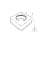
- FIG. 2 is an external perspective view of the camera module A.
- FIG. FIG. 3 is an exploded perspective view of the camera module A.
- the camera module A is mounted so that the X direction is the up / down direction (or left / right direction), the Y direction is the left / right direction (or up / down direction), and the Z direction is the front / rear direction when shooting is actually performed with the smartphone M.
- the Z direction is the optical axis direction
- the upper side in the figure is the optical axis direction light receiving side (also referred to as “macro position side”)
- the lower side is the optical axis direction imaging side (also referred to as “infinity position side”).
- the camera module A includes a lens portion (not shown) in which a lens is accommodated in a cylindrical lens barrel, a lens driving device 1 for autofocus, a shield cover 2 that covers the whole, and the like.
- the shield cover 2 is a square-shaped covered quadrangular cylinder in a plan view seen from the optical axis direction, and has a circular opening 2a on the upper surface. A lens portion (not shown) faces the outside through the opening 2a.
- the shield cover 2 is fixed to the base member 21 (see FIG. 6) of the lens driving device 1.
- the shield cover 2 is electrically connected to the image sensor substrate 22 (see FIG. 6) via a terminal fitting (not shown) of the base member 21 and grounded. EMC noise can be blocked by the shield cover 2.
- FIG. 4 is an exploded perspective view of the lens driving device 1.
- the lens driving device 1 includes an AF driving unit 10, a base unit 20, a support member 30, and the like.
- the AF drive unit 10 is disposed apart from the base unit 20 on the light receiving side in the optical axis direction, and is connected to the base unit 20 by the support member 30.
- the support member 30 includes four suspension wires extending along the Z direction (hereinafter referred to as “suspension wire 30”).
- One end (upper end) of the suspension wire 30 is fixed to the AF drive unit 10 (upper elastic support unit 13), and the other end (lower end) is fixed to the base unit 20 (terminal fitting 211, see FIG. 6).
- Two of the four suspension wires 30 are used as power feeding paths to the AF coil section 112 (see FIG. 5).
- the number of suspension wires 30 is not limited to this, and may be more than four.
- FIG. 5 is an exploded perspective view of the AF drive unit 10.
- the AF drive unit 10 includes an AF movable unit 11, an AF fixing unit 12, an upper elastic support unit 13, a lower elastic support unit 14, and the like.
- the AF movable part 11 is arranged to be spaced radially inward with respect to the AF fixing part 12 and is connected to the AF fixing part 12 by an upper elastic support part 13 and a lower elastic support part 14.
- the AF movable part 11 has a coil part that constitutes a voice coil motor for AF, and is a part that moves in the optical axis direction during focusing.
- the AF fixing part 12 is a part having a magnet part that constitutes an AF voice coil motor. In other words, the moving coil method is adopted for the AF driving unit 10 of the lens driving device 1.
- the AF movable unit 11 includes a lens holder 111 and an AF coil unit 112.
- the lens holder 111 is a rectangular tube-shaped member, and a lens portion (not shown) is fixed to the cylindrical lens housing portion 111a by bonding or screwing.
- the lens holder 111 has an upper flange portion 111b and a lower flange portion 111c on the peripheral surface of the lens housing portion 111a.
- the coil portion for AF 112 is wound around a portion (hereinafter referred to as “coil winding portion”) sandwiched between the upper flange portion 111b and the lower flange portion 111c.
- the four corners of the upper flange portion 111b are formed to be recessed by one step from the surrounding reference surface (upper surface).
- the upper flange portion 111b has a notch portion 111d at the approximate center of the periphery extending in the X direction.
- the upper flange portion 111b has two projecting portions 111e facing the Y direction on the upper outer periphery of the lens housing portion 111a. Further, the upper flange portion 111b has two protrusions 111f facing the X direction on the outer periphery of the upper portion of the lens housing portion 111a.
- the protruding portions 111e and 111f serve as an upper spring fixing portion for fixing the upper elastic support portion 13 (hereinafter referred to as “upper spring fixing portion 111e” and “upper spring fixing portion 111f”). Further, the outer end portion of the pair of upper spring fixing portions 111e is bent downward (on the image forming side in the optical axis direction) and is located at the notch portion 111d.
- the four corners of the lower flange portion 111c are formed to be recessed by one step from the surrounding reference surface (coil contact surface).
- the lower flange portion 111c has two projecting portions 111g facing the Y direction on the outer periphery of the lower portion of the lens housing portion 111a. Further, the lower flange portion 111c has two protrusions 111h facing the X direction on the lower outer periphery of the lens housing portion 111a.
- the lower surface of the protruding portion 111h is flush with the lower surfaces of the four corners of the lower flange portion 111c.
- the protruding portions 111g and 111h serve as a lower spring fixing portion for fixing the lower elastic support portion 14 (hereinafter referred to as “lower spring fixing portion 111g” and “lower spring fixing portion 111h”).
- the AF coil portion 112 is an air-core coil that is energized during focusing, and is wound around the outer peripheral surface of the coil winding portion of the lens holder 111. Both ends of the AF coil portion 112 are entangled with the upper spring fixing portions 111e and 111e of the lens holder 111.
- the AF fixing unit 12 includes a magnet holder 121 and a magnet unit 122.
- the magnet holder 121 has a square cylinder shape that is square in plan view.
- the magnet holder 121 has arcuate groove portions 121a formed at the four corners so as to be recessed inward in the radial direction.
- the suspension wire 30 is disposed in the arc groove 121a.
- the magnet holder 121 has upper spring fixing portions 121b for fixing the upper elastic support portion 13 at the upper four corners.
- the upper spring fixing portion 121b is formed to project radially inward, and contacts the four corners of the lens holder 111 when the AF movable portion 11 moves to the light receiving direction in the optical axis direction. Restricts movement to the direction light receiving side.
- the magnet holder 121 has a protruding portion 121c that protrudes upward (on the light receiving side in the optical axis direction) at the approximate center of each upper side.
- the lower elastic support portion 14 is fixed to the lower surface 121d of the magnet holder 121 (hereinafter referred to as “lower spring fixing portion 121d”).
- the magnet holder 121 has a quadrangular opening 121e on four side walls.
- the magnet portion 122 is accommodated in the opening (hereinafter referred to as “magnet accommodating portion 121e”).
- the magnet part 122 is composed of four rectangular parallelepiped permanent magnets 122A to 122D.
- the permanent magnets 122A to 122D are respectively disposed in the magnet accommodating portion 121e of the magnet holder 121.
- Permanent magnets 122A and 122B are disposed facing the X direction, and permanent magnets 122C and 122D are disposed facing the Y direction.
- the permanent magnets 122A to 122D are magnetized so that a magnetic field transverse to the radial direction is formed in the AF coil portion 112.
- the permanent magnets 122A to 122D are magnetized with an N pole on the inner peripheral side and an S pole on the outer peripheral side.
- the magnet section 122 and the AF coil section 112 constitute an AF voice coil motor.
- the upper elastic support portion 13 is a leaf spring made of, for example, beryllium copper, nickel copper, stainless steel or the like, and has a square shape as a whole in plan view.
- the upper elastic support portion 13 elastically supports the AF movable portion 11 with respect to the AF fixed portion 12.
- the upper elastic support portion 13 includes two upper leaf springs 131 and 132 that are arranged point-symmetrically.
- the upper leaf springs 131 and 132 are formed by punching and cutting a single sheet metal, for example. Since the upper leaf springs 131 and 132 have the same configuration, the description of the upper leaf spring 132 is omitted.
- the upper leaf spring 131 has lens holder fixing portions 131a and 131b, magnet holder fixing portions 131c and 131d, and arm portions 131e and 131f.
- the lens holder fixing portions 131a and 131b are connected by an inner edge portion 131g along the upper surface of the lens housing portion 111a of the lens holder 111.
- the magnet holder fixing portions 131c and 131d are connected by an outer edge portion 131h along the protruding portion 121c of the magnet holder 121.
- the lens holder fixing portions 131a and 131b have shapes corresponding to the upper spring fixing portions 111e and 111f of the lens holder 111.
- the fixing holes 131j of the lens holder fixing portions 131a and 131b into the positioning boss 111j of the lens holder 111, the upper leaf spring 131 is positioned with respect to the lens holder 111, and an adhesive is applied to the positioning boss 111j.
- the positioning boss 111j is fixed by heat caulking.
- One lens holder fixing portion 131a is fixed to the upper spring fixing portion 111e of the lens holder 111, and is electrically connected to the AF coil portion 112 entangled with the upper spring fixing portion 111e.
- the magnet holder fixing portions 131c and 131d have a shape corresponding to the upper spring fixing portion 121b of the magnet holder 121.
- the fixing holes 131k of the magnet holder fixing portions 131c and 131d into the positioning boss 121k of the magnet holder 121, the upper leaf spring 131 is positioned with respect to the magnet holder 121, and an adhesive is applied to the positioning boss 121k.
- the positioning boss 121k is fixed by heat caulking.
- the apex angle portions 131i of the magnet holder fixing portions 131c and 131d serve as wire connection portions to which the suspension wire 30 is connected (hereinafter referred to as “wire connection portions 131i”).
- the wire connecting portion 131i is located on the light receiving side in the optical axis direction of the arc groove portion 121a of the magnet holder 121. In a state where the upper leaf spring 131 is attached to the magnet holder 121, a gap is formed between the wire connection portion 131i and the arc groove portion 121a. A damper material is disposed in the gap. Further, the wire connecting portion 131i has a shape that is easily elastically deformed. Due to the bending of the wire connecting portion 131i and the suspension wire 30, the impact at the time of dropping is absorbed. Therefore, it is possible to effectively prevent the suspension wire 30 from being plastically deformed or broken due to a drop impact.
- the arm portions 131e and 131f connect the lens holder fixing portion 131a and the magnet holder fixing portion 131c, and the lens holder fixing portion 131b and the magnet holder fixing portion 131d, respectively.
- the arm portions 131e and 131f have a zigzag shape and are elastically deformed when the AF movable portion 11 moves.
- the lower elastic support portion 14 has substantially the same configuration as the upper elastic support portion 13. That is, the lower elastic support portion 14 is a leaf spring made of, for example, beryllium copper, nickel copper, stainless steel, or the like, and has a square shape as a whole in plan view.
- the lower elastic support portion 14 elastically supports the AF movable portion 11 with respect to the AF fixed portion 12.
- the lower elastic support portion 14 includes two lower leaf springs 141 and 142 that are arranged point-symmetrically.
- the lower leaf springs 141 and 142 are formed by punching and cutting a single sheet metal, for example. Since the lower leaf springs 141 and 142 have the same configuration, the description of the lower leaf spring 142 is omitted.
- the lower leaf spring 141 has lens holder fixing portions 141a and 141b, magnet holder fixing portions 141c and 141d, and arm portions 141e and 141f.
- the lens holder fixing portions 141a and 141b are connected by an inner edge portion 141g along the lower surface of the lens housing portion 111a of the lens holder 111.
- the lens holder fixing portions 141a and 141b have shapes corresponding to the lower spring fixing portions 111g and 111h of the lens holder 111.
- the fixing holes 141m of the lens holder fixing portions 141a and 141b are inserted into the positioning boss (not shown) of the lens holder 111, whereby the lower leaf spring 141 is positioned with respect to the lens holder 111, and an adhesive is applied to the positioning boss.
- the application or positioning boss is fixed by heat caulking.
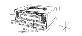
- the lens holder fixing portion 141a functions as a reflecting plate that reflects the light emitted from the reflective photoreflector 24 (see FIG. 6). Since the lower leaf spring 141 is made of a metal material, a part of this can be used as a reflector. As a result, it is not necessary to attach a reflection plate separate from the constituent members of the AF movable portion 11 to the AF movable portion 11, so that the component cost does not increase and the assembly work does not become complicated. Further, since the weight of the AF movable part 11 does not increase, good response sensitivity is ensured.
- the lower leaf spring 14 is preferably made of stainless steel. Moreover, it is preferable that mirror processing such as plating is performed on the lower surface of the lens holder fixing portion 141a that functions as a reflecting plate (the surface facing the reflective photoreflector 24 (see FIG. 6)). As a result, it is possible to increase the reflection efficiency in the lens holder fixing portion 141a, and it is possible to prevent the reflectance from fluctuating due to surface oxidation or corrosion. If the reflection efficiency can be secured, a transparent tape or a transparent paint may be applied to protect the surface.
- the magnet holder fixing portions 141c and 141d have a shape corresponding to the lower spring fixing portion 121d of the magnet holder 121.
- the fixing holes 141n of the magnet holder fixing portions 141c and 141d into the positioning boss (not shown) of the magnet holder 121, the lower leaf spring 141 is positioned with respect to the magnet holder 121, and an adhesive is attached to the positioning boss.
- the application or positioning boss is fixed by heat caulking.
- the arm portions 141e and 141f connect the lens holder fixing portion 141a and the magnet holder fixing portion 141c, and the lens holder fixing portion 141b and the magnet holder fixing portion 141d, respectively.
- the arm portions 141e and 141f have a zigzag shape, and elastically deform when the AF movable portion 11 moves.
- the magnet unit 122 is accommodated in the magnet accommodating part 121e of the magnet holder 121, and the upper elastic support part 13 is attached to the upper spring fixing part 121b.
- the lower leaf spring 14 is attached to the lower spring fixing portions 111g and 111h of the lens holder 111, and in this state, the lens holder 111 is inserted into the magnet holder 121 from the optical axis direction imaging side.
- the upper leaf springs 131 and 132 are attached to the upper spring fixing portions 111e and 111f of the lens holder 111.
- the lower leaf spring 14 is attached to the lower spring fixing portion 121 d of the magnet holder 121.
- the lens holder fixing portions 131a and 132a of the upper leaf springs 131 and 132 are soldered and electrically connected to the end portions of the AF coil portion 112 entangled with the upper spring fixing portions 111e and 111e of the lens holder 111, respectively. Is done. In this way, the AF driving unit 10 is assembled.
- FIG. 6 is an exploded perspective view of the base portion 20.
- the base unit 20 includes a base member 21, an image sensor substrate 22, an image sensor 23, a reflective photo reflector 24, and the like.
- the base unit 20 is disposed on the optical axis direction imaging side of the AF driving unit 10.
- the base unit 20 is an imaging unit that captures a subject image formed by a lens unit (not shown).
- the base member 21 is a square member in plan view, and has a square opening 21a at the center. Further, the base member 21 has a notch 213 at a position corresponding to the reflective photoreflector 24.
- the terminal fitting 211 and the like are embedded in the base member 21 by insert molding. One end of the terminal fitting 211 is exposed from the four corners of the base member 21, and the other end (not shown) is exposed from the lower portion of the base member 21. One end of the terminal fitting 211 is connected to the other end (lower end) of the suspension wire 30, and the other end is electrically connected to a power supply line (not shown) of the image sensor substrate 22.
- the base member 21 has a cover mounting portion 212 at the peripheral edge.
- the cover attachment portion 212 includes a protruding portion 212a that protrudes upward from the reference surface (upper surface) of the base member 21, and a step portion 212b that is recessed downward from the reference surface.
- the shield cover 2 is fitted to the cover mounting portion 212 in a state where the shield cover 2 is positioned by the protruding portion 212a, and is adhered to the step portion 212b.
- a terminal fitting (not shown) is embedded in the cover mounting portion 212, and the shield cover 2 is electrically connected to the image sensor substrate 22 through the terminal fitting and grounded.
- the image sensor substrate 22 is a square substrate in plan view like the base member 21.
- the image sensor substrate 22 has a frame portion 221 that protrudes above the reference surface (mounting surface of the image sensor 23) and to which the base member 21 is bonded.
- the frame portion 221 forms a recess for mounting the image sensor 23 and the reflective photoreflector 24.
- the image sensor 23 is mounted substantially at the center of the image sensor substrate 22.
- the image pickup device 23 is constituted by, for example, a charge-coupled device (CCD) type image sensor, a complementary metal oxide (CMOS) type image sensor, or the like.
- CCD charge-coupled device
- CMOS complementary metal oxide
- the image sensor 23 captures a subject image formed by a lens unit (not shown).
- the reflective photo reflector 24 is mounted on the image sensor substrate 22 at a position corresponding to the lens holder fixing portion 141a of the lower leaf spring 14.
- the reflection type photo reflector 24 is an optical sensor having a light emitting part and a light receiving part in one semiconductor package. As shown in FIGS. 7 and 8, the reflective photoreflector 24 faces the AF movable portion 11 side through the notch 213 of the base member 21, and reflects the reflection plate (here, the lower leaf spring 14 of the lower leaf spring 14). Infrared rays are emitted toward the lens holder fixing portion 141a). Then, the position of the AF movable unit 11 is detected from the intensity of the reflected light that is reflected by the reflecting plate and enters the light receiving unit.
- the reflective photoreflector is mounted apart from the AF movable portion 11 in the optical axis direction, and the AF movable portion is moved. It is necessary to arrange a reflector (for example, an aluminum mirror) in the portion 11.
- a reflector for example, an aluminum mirror
- a part of the member that is displaced together with the AF movable portion 11, here, the lens holder fixing portion 141 a of the lower leaf spring 14 is used as a reflection plate for the reflection type photoreflector, so that new parts are arranged. There is no need.
- one end of the suspension wire 30 is inserted into the wire connecting portion 131i of the upper leaf spring 131 of the AF driving portion 10 and fixed by soldering.
- the other end (lower end) of the suspension wire 30 is inserted into the terminal fitting 211 of the base member 21 and fixed by soldering. Power is supplied to the AF coil portion 112 via the suspension wire 30 and the upper elastic support portion 13.
- a damper material is disposed so as to surround the suspension wire 30.
- the damper material is interposed between the upper elastic support portion 13 and the magnet holder 121. Since a damper material (not shown) is interposed between the upper elastic support portion 13 and the magnet holder 121, the occurrence of unnecessary resonance (higher-order resonance mode) is suppressed, so that operational stability is ensured. Can do.
- the damper material can be easily applied using a dispenser. As the damper material, for example, an ultraviolet curable silicone gel can be applied.
- the AF coil unit 112 When automatic focusing is performed in the lens driving device 1, the AF coil unit 112 is energized.
- Lorentz force is generated in the AF coil unit 112 due to the interaction between the magnetic field of the magnet unit 122 and the current flowing through the AF coil unit 112.
- the direction of the Lorentz force is a direction (Z direction) orthogonal to the direction of the magnetic field (X direction or Y direction) and the direction of the current flowing in the AF coil section 112 (Y direction or X direction). Since the magnet portion 122 is fixed, a reaction force acts on the AF coil portion 112. This reaction force becomes the driving force of the voice coil motor for AF, and the AF movable portion 11 having the AF coil portion 112 moves in the optical axis direction, and focusing is performed.
- closed loop control is performed based on the detection signal of the reflective photoreflector 24 (position detection unit). According to the closed loop control method, it is not necessary to consider the hysteresis characteristics of the voice coil motor, and it is possible to directly detect that the position of the AF movable portion 11 is stable. Furthermore, automatic focusing of the image plane detection method can also be supported. Therefore, the response performance is high, and the speed of the automatic focusing operation can be increased.
- the lens driving device 1 includes the AF coil unit 112 disposed around the lens unit (not shown), and the magnet unit 122 (disposed in the radial direction with respect to the AF coil unit 112).
- the AF fixing portion 12 including the magnet portion 122 is used for AF by using the driving force of a voice coil motor including the AF coil portion 112 and the magnet portion 122. Focusing is automatically performed by moving the AF movable part 11 including the coil part 112 in the optical axis direction.
- the lens driving device 1 is disposed away from the AF movable portion 11 on the image forming side in the optical axis direction, emits light toward the AF movable portion 11, and is reflected by the AF movable portion 11.
- a reflective photoreflector 24 position detection unit that detects the position of the AF movable unit 11 in the optical axis direction based on the received light intensity.
- the lens holder fixing portion 141a (a part of the member displaced together with the AF movable portion 11) of the lower leaf spring 14 functions as a reflecting plate that reflects the light emitted from the reflective photoreflector 24.
- a part of the lower leaf spring 14 that is displaced together with the AF movable portion 11 is used as a reflecting plate. 24 can be implemented. Therefore, it is extremely useful when automatic focusing is performed by the closed loop control method using the reflective photoreflector 24.
- a specific portion of the lens holder 111 may function as a reflector.
- at least a specific portion of the lens holder 111 is preferably made of a white (natural color) resin material.
- the lens holder 111 is made of a black resin material, but only a specific portion can be made of a white resin material by two-color molding (double molding).
- the AF driving unit 10 of the lens driving device 1 may adopt a moving magnet system in which an AF magnet unit is arranged in the AF movable unit 11 and an AF coil unit is arranged in the AF fixing unit 12. Good.
- the present invention is applied to a lens driving device having an AF function and a shake correction function (so-called OIS function, OIS: Optical Image Stabilization) that optically corrects camera shake (vibration) that occurs during shooting to reduce image distortion.
- OIS function OIS: Optical Image Stabilization
- a smartphone as a mobile terminal with a camera is described as an example of a camera mounting device including the camera module A, but the present invention can be applied to a camera mounting device as an information device or a transport device.
- An on-camera device that is an information device is an information device having a camera module and a control unit that processes image information obtained by the camera module.
- a camera-equipped mobile phone, a notebook computer, a tablet terminal, and a portable game machine Web cameras, and in-vehicle devices with cameras (for example, back monitor devices, drive recorder devices).
- the camera mounting apparatus which is a transport apparatus is a transport apparatus which has a control part which processes a camera module and the image acquired with the camera module, for example, includes a motor vehicle.
- FIG. 9 is a diagram showing a car C as a camera mounting device on which a camera module VC (Vehicle Camera) is mounted.
- 9A is a front view of the automobile C
- FIG. 9B is a rear perspective view of the automobile C.
- the automobile C mounts the camera module A described in the embodiment as the in-vehicle camera module VC.
- the in-vehicle camera module VC is attached to the windshield, for example, facing forward, or attached to the rear gate facing backward.
- This in-vehicle camera module VC is used for a back monitor, a drive recorder, a collision avoidance control, an automatic driving control, and the like.
- Lens drive device 2 Shield cover 10 AF drive part 11 AF movable part 111 Lens holder 112 AF coil part 12 AF fixed part 121 Magnet holder 122 Magnet part 122A-122D Permanent magnet 13 Upper elastic support part 131, 132 Upper leaf
Landscapes
- Physics & Mathematics (AREA)
- Engineering & Computer Science (AREA)
- Multimedia (AREA)
- Signal Processing (AREA)
- General Physics & Mathematics (AREA)
- Optics & Photonics (AREA)
- Electromagnetism (AREA)
- General Engineering & Computer Science (AREA)
- Spectroscopy & Molecular Physics (AREA)
- Lens Barrels (AREA)
- Studio Devices (AREA)
Abstract
Description
前記オートフォーカス可動部に対して光軸方向結像側に離間して配置され、前記オートフォーカス可動部に向けて光を出射するとともに、前記オートフォーカス可動部で反射した反射光を受光して、受光強度に基づいて前記オートフォーカス可動部の光軸方向の位置を検出する位置検出部を備え、
前記オートフォーカス可動部とともに変位する部材の一部が、前記位置検出部から出射された光を反射する反射板として機能することを特徴とする。
前記オートフォーカス可動部に装着されるレンズ部と、
前記レンズ部により結像された被写体像を撮像する撮像部と、を備えることを特徴とする。
上記のカメラモジュールを備えることを特徴とする。
図1は、本発明の一実施の形態に係るカメラモジュールAを搭載するスマートフォンM(カメラ搭載装置)を示す図である。図1AはスマートフォンMの正面図であり、図1BはスマートフォンMの背面図である。
2 シールドカバー
10 AF用駆動部
11 AF可動部
111 レンズホルダー
112 AF用コイル部
12 AF固定部
121 マグネットホルダー
122 マグネット部
122A~122D 永久磁石
13 上側弾性支持部
131、132 上側板バネ
14 下側弾性支持部
141、142 下側板バネ
141a レンズホルダー固定部(反射板)
20 ベース部(撮像部)
21 ベース部材
22 イメージセンサー基板
23 撮像素子
24 反射型フォトリフレクタ(位置検出部)
30 支持部材
M スマートフォン(カメラ搭載装置)
A カメラモジュール
Claims (9)
- レンズ部の周囲に配置されるオートフォーカス用コイル部と、前記オートフォーカス用コイル部に対して径方向に離間して配置されるオートフォーカス用マグネット部とを有し、前記オートフォーカス用コイル部と前記オートフォーカス用マグネット部とで構成されるボイスコイルモーターの駆動力を利用して、前記オートフォーカス用コイル部及び前記オートフォーカス用マグネット部の何れか一方を含むオートフォーカス固定部に対して、前記オートフォーカス用コイル部及び前記オートフォーカス用マグネット部の何れか他方を含むオートフォーカス可動部を光軸方向に移動させることにより自動的にピント合わせを行うレンズ駆動装置であって、
前記オートフォーカス可動部に対して光軸方向結像側に離間して配置され、前記オートフォーカス可動部に向けて光を出射するとともに、前記オートフォーカス可動部で反射した反射光を受光して、受光強度に基づいて前記オートフォーカス可動部の光軸方向の位置を検出する位置検出部を備え、
前記オートフォーカス可動部とともに変位する部材の一部が、前記位置検出部から出射された光を反射する反射板として機能することを特徴とするレンズ駆動装置。 - 前記オートフォーカス可動部の下面に配置され、前記オートフォーカス可動部を前記オートフォーカス固定部に対して弾性支持する下側弾性支持部を備え、
前記下側弾性支持部の前記オートフォーカス可動部に固定される固定部位が、前記反射板として機能することを特徴とする請求項1に記載のレンズ駆動装置。 - 前記下側弾性支持部は、ステンレス系材料で構成されることを特徴とする請求項2に記載のレンズ駆動装置。
- 前記固定部位には、鏡面加工が施されていることを特徴とする請求項2又は3に記載のレンズ駆動装置。
- 前記固定部位には、めっき処理が施されていることを特徴とする請求項4に記載のレンズ駆動装置。
- 前記オートフォーカス可動部は、前記レンズ部を保持するレンズホルダーを有し、
前記レンズホルダーの特定部位が、前記反射板として機能することを特徴とする請求項1に記載のレンズ駆動装置。 - 前記レンズホルダーの特定部位は、白色系の樹脂材料で構成されることを特徴とする請求項6に記載のレンズ駆動装置。
- 請求項1から7のいずれか一項に記載のレンズ駆動装置と、
前記オートフォーカス可動部に装着されるレンズ部と、
前記レンズ部により結像された被写体像を撮像する撮像部と、を備えることを特徴とするカメラモジュール。 - 情報機器または輸送機器であるカメラ搭載装置であって、
請求項8に記載のカメラモジュールを備えることを特徴とするカメラ搭載装置。
Priority Applications (3)
| Application Number | Priority Date | Filing Date | Title |
|---|---|---|---|
| CN201580069860.3A CN107111096B (zh) | 2014-12-26 | 2015-12-24 | 透镜驱动装置、摄像机模块、以及摄像机搭载装置 |
| US15/539,379 US10495844B2 (en) | 2014-12-26 | 2015-12-24 | Lens drive device, camera module, and camera-mounting device |
| KR1020177017563A KR102537831B1 (ko) | 2014-12-26 | 2015-12-24 | 렌즈 구동장치, 카메라 모듈, 및 카메라 탑재 장치 |
Applications Claiming Priority (2)
| Application Number | Priority Date | Filing Date | Title |
|---|---|---|---|
| JP2014265983A JP6503735B2 (ja) | 2014-12-26 | 2014-12-26 | レンズ駆動装置、カメラモジュール、及びカメラ搭載装置 |
| JP2014-265983 | 2014-12-26 |
Publications (1)
| Publication Number | Publication Date |
|---|---|
| WO2016103698A1 true WO2016103698A1 (ja) | 2016-06-30 |
Family
ID=56149756
Family Applications (1)
| Application Number | Title | Priority Date | Filing Date |
|---|---|---|---|
| PCT/JP2015/006424 Ceased WO2016103698A1 (ja) | 2014-12-26 | 2015-12-24 | レンズ駆動装置、カメラモジュール、及びカメラ搭載装置 |
Country Status (6)
| Country | Link |
|---|---|
| US (1) | US10495844B2 (ja) |
| JP (1) | JP6503735B2 (ja) |
| KR (1) | KR102537831B1 (ja) |
| CN (1) | CN107111096B (ja) |
| TW (1) | TWI667508B (ja) |
| WO (1) | WO2016103698A1 (ja) |
Cited By (1)
| Publication number | Priority date | Publication date | Assignee | Title |
|---|---|---|---|---|
| CN110018601A (zh) * | 2017-12-14 | 2019-07-16 | 阿诺尔德-里希特电影技术两合公司 | 具有基于激光的测距仪的摄像机系统 |
Families Citing this family (10)
| Publication number | Priority date | Publication date | Assignee | Title |
|---|---|---|---|---|
| JP6217811B2 (ja) * | 2016-07-29 | 2017-10-25 | 井関農機株式会社 | コンバイン |
| JP7021434B2 (ja) * | 2018-02-05 | 2022-02-17 | ミツミ電機株式会社 | レンズ駆動装置、カメラモジュール、及びカメラ搭載装置 |
| CN110118766B (zh) * | 2018-02-07 | 2024-05-14 | 高利通科技(深圳)有限公司 | 手持式通用物质分析系统 |
| JP6976201B2 (ja) * | 2018-03-13 | 2021-12-08 | 京セラ株式会社 | 固定構造、電子機器、撮像装置、移動体、および固定構造の製造方法 |
| JP7096107B2 (ja) * | 2018-08-31 | 2022-07-05 | 日本電産サンキョー株式会社 | 光学ユニット |
| KR20220007048A (ko) * | 2019-05-10 | 2022-01-18 | 미니스뷔스 에스에이 | 렌즈 구동 장치, 카메라 모듈, 및 카메라 탑재 장치 |
| US11573393B2 (en) * | 2020-05-04 | 2023-02-07 | Apple Inc. | Camera with base cutout for position sensing arrangement |
| CN111970421B (zh) | 2020-08-17 | 2022-03-22 | Oppo广东移动通信有限公司 | 摄像头马达、摄像头模组和电子装置 |
| CN116614698A (zh) * | 2023-06-28 | 2023-08-18 | 维沃移动通信有限公司 | 摄像模组和电子设备 |
| CN222339499U (zh) * | 2023-12-29 | 2025-01-10 | 华为技术有限公司 | 镜头驱动装置、摄像头模组及电子设备 |
Citations (4)
| Publication number | Priority date | Publication date | Assignee | Title |
|---|---|---|---|---|
| JP2006227274A (ja) * | 2005-02-17 | 2006-08-31 | Konica Minolta Opto Inc | 撮像装置 |
| JP2006337809A (ja) * | 2005-06-03 | 2006-12-14 | Fujinon Corp | レンズ組立体 |
| JP2010160404A (ja) * | 2009-01-09 | 2010-07-22 | Panasonic Corp | カメラモジュール |
| JP2013210550A (ja) * | 2012-03-30 | 2013-10-10 | Mitsumi Electric Co Ltd | レンズホルダ駆動装置、カメラモジュール、およびカメラ付き携帯端末 |
Family Cites Families (15)
| Publication number | Priority date | Publication date | Assignee | Title |
|---|---|---|---|---|
| JPS53113743A (en) * | 1977-03-16 | 1978-10-04 | Toyo Radiator Kk | Manufacture of aluminum made heat exchanger |
| US7818138B2 (en) | 2006-04-27 | 2010-10-19 | Asahi Kasei Emd Corporation | Position detecting device and position detecting method |
| TWI317202B (en) * | 2006-07-28 | 2009-11-11 | Ind Tech Res Inst | Actuator |
| US7759634B2 (en) * | 2007-04-24 | 2010-07-20 | Mitsumi Electric Co., Ltd. | Position detecting device capable of improving detection accuracy |
| JP4642053B2 (ja) * | 2007-09-14 | 2011-03-02 | 三洋電機株式会社 | レンズ駆動装置 |
| JP5846346B2 (ja) | 2009-08-21 | 2016-01-20 | ミツミ電機株式会社 | カメラの手振れ補正装置 |
| KR101156872B1 (ko) * | 2009-12-18 | 2012-06-20 | 삼성전기주식회사 | 렌즈 구동 모듈 |
| JP5612390B2 (ja) | 2010-08-06 | 2014-10-22 | 日本電産サンキョー株式会社 | 光学ユニット |
| US9151963B2 (en) | 2011-08-24 | 2015-10-06 | Mitsumi Electric Co., Ltd. | Lens holder driving device including damper compound suppressing undesired resonance |
| CN102419505B (zh) * | 2011-12-06 | 2014-08-06 | 深圳英飞拓科技股份有限公司 | 自动聚焦方法及系统和一体化摄像机 |
| JP2014126668A (ja) * | 2012-12-26 | 2014-07-07 | Mitsumi Electric Co Ltd | レンズ駆動装置、カメラモジュール、及びカメラ付き携帯端末 |
| TWI544723B (zh) * | 2013-11-29 | 2016-08-01 | 台灣東電化股份有限公司 | 電磁驅動模組及應用該電磁驅動模組之鏡頭裝置 |
| JP5760116B2 (ja) * | 2014-04-14 | 2015-08-05 | シャープ株式会社 | カメラモジュール |
| CN104023175B (zh) * | 2014-04-25 | 2017-07-28 | 深圳英飞拓科技股份有限公司 | 一种自动聚焦方法和装置 |
| JP2017049343A (ja) * | 2015-08-31 | 2017-03-09 | ミツミ電機株式会社 | レンズ駆動装置、カメラモジュール、及びカメラ搭載装置 |
-
2014
- 2014-12-26 JP JP2014265983A patent/JP6503735B2/ja not_active Expired - Fee Related
-
2015
- 2015-12-24 KR KR1020177017563A patent/KR102537831B1/ko active Active
- 2015-12-24 WO PCT/JP2015/006424 patent/WO2016103698A1/ja not_active Ceased
- 2015-12-24 US US15/539,379 patent/US10495844B2/en not_active Expired - Fee Related
- 2015-12-24 CN CN201580069860.3A patent/CN107111096B/zh active Active
- 2015-12-25 TW TW104143670A patent/TWI667508B/zh not_active IP Right Cessation
Patent Citations (4)
| Publication number | Priority date | Publication date | Assignee | Title |
|---|---|---|---|---|
| JP2006227274A (ja) * | 2005-02-17 | 2006-08-31 | Konica Minolta Opto Inc | 撮像装置 |
| JP2006337809A (ja) * | 2005-06-03 | 2006-12-14 | Fujinon Corp | レンズ組立体 |
| JP2010160404A (ja) * | 2009-01-09 | 2010-07-22 | Panasonic Corp | カメラモジュール |
| JP2013210550A (ja) * | 2012-03-30 | 2013-10-10 | Mitsumi Electric Co Ltd | レンズホルダ駆動装置、カメラモジュール、およびカメラ付き携帯端末 |
Cited By (2)
| Publication number | Priority date | Publication date | Assignee | Title |
|---|---|---|---|---|
| CN110018601A (zh) * | 2017-12-14 | 2019-07-16 | 阿诺尔德-里希特电影技术两合公司 | 具有基于激光的测距仪的摄像机系统 |
| CN110018601B (zh) * | 2017-12-14 | 2022-07-22 | 阿诺尔德-里希特电影技术两合公司 | 具有基于激光的测距仪的摄像机系统 |
Also Published As
| Publication number | Publication date |
|---|---|
| CN107111096A (zh) | 2017-08-29 |
| JP6503735B2 (ja) | 2019-04-24 |
| TWI667508B (zh) | 2019-08-01 |
| KR20170095902A (ko) | 2017-08-23 |
| US20170363839A1 (en) | 2017-12-21 |
| JP2016126117A (ja) | 2016-07-11 |
| US10495844B2 (en) | 2019-12-03 |
| CN107111096B (zh) | 2020-01-03 |
| KR102537831B1 (ko) | 2023-05-30 |
| TW201624039A (zh) | 2016-07-01 |
Similar Documents
| Publication | Publication Date | Title |
|---|---|---|
| JP6503735B2 (ja) | レンズ駆動装置、カメラモジュール、及びカメラ搭載装置 | |
| CN106461907B (zh) | 透镜驱动装置、摄像机模块、以及搭载有摄像机的移动终端 | |
| JP6459504B2 (ja) | レンズ駆動装置、カメラモジュール、及びカメラ搭載装置 | |
| CN107615125B (zh) | 透镜驱动装置、摄像机模块、以及摄像机搭载装置 | |
| JP6565911B2 (ja) | レンズ駆動装置、カメラモジュール、及びカメラ搭載装置 | |
| JP6492654B2 (ja) | レンズ駆動装置、カメラモジュール、及びカメラ搭載装置 | |
| EP3276411B1 (en) | Lens drive device, camera module, and camera-equipped device | |
| JP6565340B2 (ja) | レンズ駆動装置、カメラモジュール、及びカメラ搭載装置 | |
| KR20170102246A (ko) | 렌즈 구동장치, 카메라 모듈, 및 카메라 탑재 장치 | |
| KR102608087B1 (ko) | 렌즈 구동 장치, 카메라 모듈, 및 카메라 탑재 장치 | |
| JP2018018021A (ja) | レンズ駆動装置、カメラモジュール、及びカメラ搭載装置 |
Legal Events
| Date | Code | Title | Description |
|---|---|---|---|
| 121 | Ep: the epo has been informed by wipo that ep was designated in this application |
Ref document number: 15872269 Country of ref document: EP Kind code of ref document: A1 |
|
| WWE | Wipo information: entry into national phase |
Ref document number: 15539379 Country of ref document: US |
|
| ENP | Entry into the national phase |
Ref document number: 20177017563 Country of ref document: KR Kind code of ref document: A |
|
| NENP | Non-entry into the national phase |
Ref country code: DE |
|
| 122 | Ep: pct application non-entry in european phase |
Ref document number: 15872269 Country of ref document: EP Kind code of ref document: A1 |