WO2016103662A1 - 電磁アクチュエータ - Google Patents
電磁アクチュエータ Download PDFInfo
- Publication number
- WO2016103662A1 WO2016103662A1 PCT/JP2015/006301 JP2015006301W WO2016103662A1 WO 2016103662 A1 WO2016103662 A1 WO 2016103662A1 JP 2015006301 W JP2015006301 W JP 2015006301W WO 2016103662 A1 WO2016103662 A1 WO 2016103662A1
- Authority
- WO
- WIPO (PCT)
- Prior art keywords
- rod
- wall surface
- edge
- electromagnetic actuator
- hole
- Prior art date
- Legal status (The legal status is an assumption and is not a legal conclusion. Google has not performed a legal analysis and makes no representation as to the accuracy of the status listed.)
- Ceased
Links
Images








Classifications
-
- H—ELECTRICITY
- H01—ELECTRIC ELEMENTS
- H01F—MAGNETS; INDUCTANCES; TRANSFORMERS; SELECTION OF MATERIALS FOR THEIR MAGNETIC PROPERTIES
- H01F7/00—Magnets
- H01F7/06—Electromagnets; Actuators including electromagnets
- H01F7/08—Electromagnets; Actuators including electromagnets with armatures
- H01F7/121—Guiding or setting position of armatures, e.g. retaining armatures in their end position
-
- H—ELECTRICITY
- H01—ELECTRIC ELEMENTS
- H01F—MAGNETS; INDUCTANCES; TRANSFORMERS; SELECTION OF MATERIALS FOR THEIR MAGNETIC PROPERTIES
- H01F7/00—Magnets
- H01F7/06—Electromagnets; Actuators including electromagnets
- H01F7/08—Electromagnets; Actuators including electromagnets with armatures
- H01F7/16—Rectilinearly-movable armatures
- H01F7/1607—Armatures entering the winding
Definitions
- This disclosure relates to an electromagnetic actuator.
- An electromagnetic actuator in which a plunger is relatively moved in the axial direction by a magnetic force generated when a coil is energized, and an external device can be operated by a rod integral with the plunger.
- the electromagnetic actuator of Patent Document 1 is used for operating a hydraulic control valve of an engine valve timing adjusting device.
- the rod is provided so as to protrude in the axial direction from the plunger.
- the outer peripheral surface of the rod is parallel to the axis.
- the yoke forms a support portion having a through hole through which the rod is inserted.
- the rod slides with the inner wall surface of the through hole of the support portion when moving in the axial direction.
- wear of the rod and the support portion increases, and so-called twisting that makes the rod impossible to move may occur.
- the above two measures are mutually exclusive. That is, if the clearance is increased in order to reduce the frictional force between the rod and the support portion, the amount of deflection in the radial direction of the rod tip is increased. Further, if the clearance is reduced in order to reduce the amount of deflection of the rod tip in the radial direction, the frictional force between the rod and the support portion will increase.
- JP 2014-120714 A (corresponding to US 2014/0026836 A1)
- the present disclosure has been made in view of the above points, and an object of the present disclosure is to provide an electromagnetic actuator that achieves both reduction in frictional force between the rod and the support portion and reduction in the amount of deflection in the radial direction of the rod tip. Is to provide.
- the electromagnetic actuator according to the present disclosure includes a movable part, an electromagnetic drive part, and a rod.
- the movable part can reciprocate in a predetermined linear direction.
- the electromagnetic drive unit has an annular coil, and can generate a magnetic force that moves the movable unit in the linear direction when the coil is energized.
- the rod is formed so as to protrude from the movable portion in the linear direction, and is movable together with the movable portion from a maximum retracted position located on one side in the linear direction to a maximum protruding position located on the other side in the linear direction.
- the electromagnetic drive unit has a through hole through which the rod is inserted.
- the rod has an outer wall surface that slides with the through hole.
- the clearance from the outer wall surface of the rod located at the maximum projecting position to the inner wall surface of the through hole is smaller than the clearance from the outer wall surface of the rod located at the maximum retracted position to the inner wall surface.
- the clearance between the rod when the rod is positioned on the retracting side and the clearance between the inner wall surface of the through hole (retraction at the time of retracting) is relatively large, and the rod communicates with the rod when the rod is positioned on the protruding side.
- Clearance between the hole and the inner wall surface (protrusion clearance) can be made relatively small. Therefore, the frictional force between the rod and the support portion can be reduced due to the relatively large clearance during retraction.
- the clearance at the time of protrusion is relatively small, the amount of deflection of the rod tip in the radial direction can be reduced. That is, it is possible to achieve both reduction of the frictional force between the rod and the support portion and reduction of the amount of deflection in the radial direction of the rod tip.
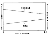
- FIG. 2 is a diagram illustrating a relationship between a stroke amount of a rod and a frictional force acting on the rod in the electromagnetic actuator of FIG.
- FIG. 20 is a diagram illustrating the relationship between the stroke amount of the rod and the frictional force acting on the rod in the electromagnetic actuator of FIG. 19 and the relationship between the stroke amount of the rod and the radial deflection amount of the rod tip.
- FIG. 20 is a diagram illustrating the relationship between the stroke amount of the rod and the frictional force acting on the rod in the electromagnetic actuator of FIG. 19 and the relationship between the stroke amount of the rod and the radial deflection amount of the rod tip.
- tip is a mimetic diagram showing a rod and a cover of an electromagnetic actuator by other embodiments of this indication.
- the electromagnetic actuator according to the first embodiment of the present disclosure is applied to the valve timing adjustment system 80 of the engine shown in FIG.
- the valve timing adjustment system 80 includes a valve timing adjustment device 81 and a hydraulic control valve 82.
- the valve timing adjustment device 81 includes a housing 84 that rotates in synchronization with the crankshaft of the engine and a vane rotor 86 that rotates integrally with the camshaft 85 of the engine, and changes the relative rotational phase between the housing 84 and the vane rotor 86.
- the vane rotor 86 rotates relative to the housing 84 in accordance with the hydraulic pressure in the hydraulic chamber (advance chamber, retard chamber) in the housing 84.
- the hydraulic pressure in the hydraulic chamber is regulated by a hydraulic control valve 82 provided at the center of the vane rotor 86.
- the hydraulic control valve 82 is a spool valve that includes a sleeve 88 having a plurality of ports 87 and a spool 89 that is movable in the axial direction within the sleeve 88, and each port 87 is changed by changing the axial position of the spool 89.
- a sleeve 88 having a plurality of ports 87 and a spool 89 that is movable in the axial direction within the sleeve 88, and each port 87 is changed by changing the axial position of the spool 89.
- the electromagnetic actuator 10 is used to change the axial position of the spool 89 of the hydraulic control valve 82.
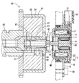
- the electromagnetic actuator 10 includes an electromagnetic drive part MD, a housing 15, a bracket 16, and a rod 17 as an “output shaft part”.
- the electromagnetic drive unit MD includes a plunger 11 as a “movable unit”, a coil 12, a yoke 13, a core stator 14, and a cover 18.
- the electromagnetic actuator 10 changes the axial position of the spool 89 of the hydraulic control valve 82 by moving the rod 17 from the maximum retracted position on one side in the axial direction to the maximum protruding position on the other side in the axial direction. .
- axial direction the direction parallel to the axis AX of the rod 17 is simply referred to as “axial direction”.
- one axial direction means the side opposite to the spool 89 with respect to the rod 17, and “the other axial direction” means the spool 89 side relative to the rod 17.
- the plunger 11 has a hollow cylindrical shape and is made of a magnetic material.
- the plunger 11 is provided on the shaft center AX and can reciprocate in the axial direction.
- the axial direction corresponds to the “linear direction” of the present disclosure.
- the coil 12 is composed of a winding wound around the outside of a resin-made and cylindrical bobbin 19.
- the bobbin 19 is provided outside the plunger 11 on the axis AX.
- the coil 12 When energized from an external power source via the terminal 21 of the connector portion 20 of the housing 15, the coil 12 generates a magnetic field.
- the yoke 13 is provided so as to surround the coil 12 in a cross section along the axis AX, and is made of a magnetic material.
- the yoke 13 includes a first yoke member 22 and a second yoke member 23.
- the first yoke member 22 has a first inner cylinder portion 24 located inside the coil 12.
- the second yoke member 23 has a second inner cylinder portion 26 that is located inside the coil 12 and is disposed with a magnetic gap 25 between the first inner cylinder portion 24.
- the first yoke member 22 and the second yoke member 23 are connected to each other outside the coil 12.
- the core stator 14 includes a shaft portion 27 located on the inner side of the plunger 11 and a flange portion 28 protruding from one end portion of the shaft portion 27 in the axial direction to the first yoke member 22.
- the housing 15 is made of resin, and is provided so as to cover a part of the outer side of the yoke 13.
- the bracket 16 is formed so as to protrude outward from the housing 15, and has a mounting hole 29 into which the fastening member 90 can be inserted.
- the rod 17 is provided so as to protrude from the plunger 11 to the other side in the axial direction, and can press the spool 89 in the axial direction.
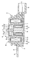
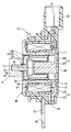
- the rod 17 is movable together with the plunger 11 from the maximum retracted position located on one side in the axial direction as shown in FIGS. 1 and 2 to the maximum projected position located on the other side in the axial direction as shown in FIG. It is.
- the maximum retracted position is a position where the rod 17 contacts the core stator 14.
- the maximum projecting position is a position where the spool 89 pushed by the rod 17 contacts the inner wall of the sleeve 88. If the electromagnetic actuator 10 is removed from the engine, the rod 17 can move further in the axial direction than the maximum projecting position.
- the plunger 11 When the rod 17 is positioned at the maximum retracted position, the plunger 11 is positioned inside the first inner cylindrical portion 24 as shown in FIG. When the rod 17 is located at the maximum projecting position, the plunger 11 is located so as to straddle the first inner cylinder part 24 and the second inner cylinder part 26 as shown in FIG.
- the cover 18 includes a fitting cylinder portion 30 that is fitted and fixed to the other axial end of the second inner cylinder portion 26, and an annular plate that protrudes radially inward from the fitting cylinder portion 30. And a support cylinder portion 32 protruding from the inner peripheral portion of the annular plate portion 31 to the other side in the axial direction.
- the support cylinder portion 32 has a through hole 33 through which the rod 17 is inserted.
- the support cylinder portion 32 can support the rod 17 that swings in the radial direction when, for example, a radial force is applied to the plunger 11.
- the plunger 11 and the rod 17 are urged to one side in the axial direction via the spool 89 by the spring 91 of the hydraulic control valve 82, and the maximum pull-in is achieved. To be positioned.
- the electromagnetic drive unit MD can generate a magnetic force that moves the plunger 11 in the axial direction.
- the edge located on one side in the axial direction among the edges of the through-hole 33 is referred to as a first edge 40.
- the edge located on the other side in the axial direction in the through hole 33 is referred to as a second edge 41.
- the 1st edge 40 forms the opening end of the axial direction one side of the through-hole 33, and is also called a 1st opening end.
- the second edge 41 forms an opening end on the other side in the axial direction of the through hole 33 and is also referred to as a second opening end.
- a portion of the rod 17 where the axial position coincides with the first edge 40 is defined as a first tip side specific portion Ps1, and the rod 17 Among these, a location where the axial position coincides with the second edge 41 is defined as a second tip side specific location Ps2.
- the first tip-side specific place Ps1 and the second tip-side specific place Ps2 are virtually shown using a two-dot chain line.
- a portion of the rod 17 where the axial position coincides with the second edge 41 is defined as the first base end side specific portion Pk1
- a portion of the rod 17 whose axial position coincides with the first edge 40 is defined as a second proximal side specific portion Pk2.
- the 1st base end side specific location Pk1 and the 2nd base end side specific location Pk2 are virtually shown using the dashed-two dotted line.
- the rod 17 has an outer wall surface 42 that can slide with the inner wall surface 34 of the through-hole 33 when moving in the axial direction.
- the outer wall surface 42 has a tapered shape whose diameter decreases from the proximal end 43 side to the distal end 44 side of the rod 17 at least in the axial range from the first proximal end specific location Pk1 to the first distal end specific location Ps1. Is formed.
- the outer wall surface 42 is tapered in the entire range from the proximal end 43 to the distal end 44.
- the “clearance between the outer wall surface 42 of the rod 17 and the inner wall surface 34 of the through-hole 33” is the minimum value of the distance from the outer wall surface 42 to the inner wall surface 34 when the rod 17 and the through-hole 33 are concentric with each other. That is.
- the clearance when the rod 17 is positioned at the maximum retracted position is CA, and the clearance when the rod 17 is positioned at the maximum protruding position is CB.
- the cover 18 is formed by pressing from a plate material.
- the inner wall surface 34 of the through-hole 33 has a tapered shape whose diameter decreases from the first edge 40 side toward the second edge 41 side.
- the gradient of the outer wall surface 42 is larger than the gradient of the inner wall surface 34 of the through hole 33. Thereby, the clearance from the outer wall surface 42 of the rod 17 to the inner wall surface 34 of the through-hole 33 is smaller toward one side in the axial direction regardless of the axial position of the rod 17.
- the gradient of the outer wall surface 42 is an angle formed by the outer wall surface 42 and the axis AX.
- the gradient of the inner wall surface 34 of the through hole 33 is an angle formed by the inner wall surface 34 of the through hole 33 and the axis AX.
- the gradient of the outer wall surface 42 and the gradient of the inner wall surface 34 of the through-hole 33 are shown larger than actual. Moreover, the clearance is shown larger than actual.
- the clearance CB when the rod 17 is located at the maximum protruding position is larger than the clearance CA when the rod 17 is located at the maximum retracted position.
- a small relationship, that is, a CA> CB relationship is established.
- the outer wall surface 101 of the rod 100 is a cylindrical surface parallel to the axis AX
- the inner wall surface 107 of the through hole 102 is a cylinder parallel to the axis AX.
- the clearance between the outer wall surface 101 of the rod 100 and the inner wall surface 107 of the through hole 102 is C1.
- the clearance C1 is set to be relatively small so as to be equivalent to the clearance CA when the rod 17 is located at the maximum projecting position in the present embodiment.
- the amount of radial deflection of the rod 100 can be kept relatively small over the entire stroke amount of the rod 100.
- the frictional force between the outer wall surface 101 and the inner wall surface 107 of the through hole 102 becomes relatively large.
- wear of the rod 100 and the support cylinder 103 increases, and so-called twisting that makes the rod 100 immovable may occur.
- the outer wall surface 106 of the rod 105 is a cylindrical surface parallel to the axis AX
- the inner wall surface 107 of the through hole 102 is a cylinder parallel to the axis AX.
- the clearance between the outer wall surface 106 of the rod 105 and the inner wall surface 107 of the through hole 102 is C2. Regardless of the axial position of the rod 105, the clearance C2 is set to be relatively large so as to be equivalent to the clearance CB when the rod 17 is positioned at the maximum retracted position in the present embodiment.
- the frictional force between the outer wall surface 106 and the inner wall surface 107 of the through hole 102 can be kept relatively small over the entire stroke amount of the rod 105.
- the amount of radial deflection of the rod 105 is relatively large.
- the force in the radial direction (side force) against the plunger is increased due to the influence of the magnetic force, and the rod 105 is greatly shaken in the radial direction.
- the clearance CA when the rod 17 is located at the maximum protruding position is equal to the clearance C1 in the first comparative embodiment, and the clearance CB when the rod 17 is located at the maximum retracted position is the first. It is equivalent to the clearance C2 in the two comparison form. Therefore, as shown in FIG. 6, the frictional force between the outer wall surface 42 and the inner wall surface 34 of the through-hole 33 is relatively reduced while the radial deflection amount of the rod 17 is relatively small over the entire stroke amount of the rod 17. It can be kept small.
- the rod 17 has the distal end 44 from the proximal end 43 side of the rod 17 in the axial range from at least the first proximal specific point Pk1 to the first distal specific point Ps1. It has a tapered outer wall surface 42 whose diameter decreases toward the side. Thereby, the clearance CB when the rod 17 is located at the maximum protruding position is smaller than the clearance CA when the rod 17 is located at the maximum retracted position.
- the rod 17 will be located in the protrusion side, making comparatively large the clearance (clearance at the time of retraction) between the rod 17 and the inner wall surface 34 of the through-hole 33 when the rod 17 is located in the drawing side.
- the clearance (protrusion clearance) between the rod 17 and the inner wall surface 34 of the through hole 33 can be made relatively small. Therefore, the frictional force between the rod 17 and the support cylinder portion 32 can be reduced due to the relatively large clearance during retraction.
- the clearance at the time of protrusion is relatively small, the amount of deflection in the radial direction of the tip 44 of the rod 17 can be reduced. That is, it is possible to achieve both reduction in the frictional force between the rod 17 and the support cylinder portion 32 and reduction in the amount of deflection in the radial direction of the tip 44 of the rod 17.
- the outer wall surface 42 is tapered at least in the axial range from the first base side specific place Pk1 to the second tip side specific place Ps2.
- the clearance at the time of retraction becomes larger than that in the case where the outer peripheral surface of the rod 17 from the first tip side specific portion Ps1 to the tip 44 side is parallel to the axial direction. Therefore, the frictional force between the rod 17 and the support cylinder portion 32 can be further reduced.
- the outer wall surface 42 is tapered in an axial range from at least the second base side specific place Pk2 to the first tip side specific place Ps1.
- the clearance at the time of protrusion becomes small compared with the case where the outer peripheral surface of the base end 43 side from the first base end side specific place Pk1 is parallel to the axial direction in the rod 17. Therefore, the amount of deflection in the radial direction of the tip 44 of the rod 17 can be further reduced.
- the inner wall surface 34 of the through hole 33 has a tapered shape whose diameter decreases from the first edge 40 side toward the second edge 41 side.
- the gradient of the outer wall surface 42 is larger than the gradient of the inner wall surface 34 of the through hole 33.
- the outer wall surface 42 and the inner wall surface 34 of the through hole 33 can be configured to come into surface contact when the rod 17 is swung in the radial direction.
- the outer wall surface 50 is tapered in the axial range from the first base-side specific place Pk1 to the first tip-side specific place Ps1.
- the outer wall surface 50 is parallel to the axial direction from the first distal end specific portion Ps1 to the distal end 44 side, and is parallel to the axial direction from the first proximal end specific portion Pk1.
- the frictional force between the rod 17 and the support cylinder portion 32 is reduced and the distal end 44 of the rod 17 is moved in the radial direction as compared with the first and second comparative embodiments. It is possible to achieve both reduction in the amount of vibration.
- the outer wall surface 60 is stepped so that the diameter of the rod 17 gradually decreases from the proximal end 43 side toward the distal end 44 side at predetermined intervals. It is formed in the attached shape.
- the interval at which the diameter of the rod 17 decreases may be set arbitrarily.
- the outer wall surface 60 is stepped with respect to the entire range from the base end 43 side to the tip end 44 side. Even in such a stepped rod, the clearance CA when the rod 17 is located at the maximum retracted position is smaller than the clearance CB when the rod 17 is located at the maximum protruding position. Therefore, the same effects as those of the first embodiment are obtained.
- the rod 17 protrudes radially outward in the axial range from the first base end specific place Pk1 to the second base end specific place Pk2. 71. Since the rod 17 has the protrusion 71, the outer wall surface 70 includes a protruding surface 72 that protrudes radially outward. Since the outer wall surface 70 includes the protruding surface 72, the clearance CA becomes smaller than the clearance CA when the rod 17 is positioned at the maximum retracted position, and the clearance CB when the rod 17 is positioned at the maximum protruding position. Therefore, the fourth embodiment also has the same effect as the first embodiment.
- the outer wall surface 51 is formed in another embodiment sharing the idea of the second embodiment, as shown in FIG. 11, in the axial range from the second base end side specific place Pk2 to the first base end side specific place Pk1, the outer wall surface 51 is formed. It is good also as a taper shape in which a diameter becomes small toward the front end 44 side from the base end 43 side.
- the outer wall surface 52 has a tapered shape whose diameter decreases from the proximal end 43 side to the distal end 44 side. It is good.
- the outer wall surface 53 has a taper whose diameter decreases from the proximal end 43 side to the distal end 44 side. It is good also as a shape.
- the outer wall surface 54 is tapered from the base end 43 side to the tip 44 side. It is good also as a shape.
- the outer wall surface 55 has a taper whose diameter decreases from the proximal end 43 side to the distal end 44 side. It is good also as a shape.
- the outer wall surface 56 may have a tapered shape whose diameter decreases from the base end 43 side toward the tip end 44 side.
- the outer wall surface is the proximal side. It is good also as a taper shape from which a diameter becomes small toward the front end side. Furthermore, in the axial range from between the first base end side specific place and the first tip end side specific place to between the first base end side specific place and the second base end specific place, the outer wall surface is set as the base end. It is good also as a taper shape from which a diameter becomes small toward the front end side.
- the rod 17 in a part of the axial range from the first distal side specific place Ps1 to the second proximal side specific place Pk2, the rod 17
- the outer wall surface 61 may have a stepped shape that is stepped. The same effect as the first embodiment is achieved.
- the rod may have a shaft and a ring that fits the shaft, and the protrusion may be formed of a ring.
- the cover is divided into a plurality of cover bodies, and the plurality of cover bodies are operable radially inward using a driving unit different from the movable unit.
- the rod may be composed of the same member as the plunger.
- the cover is not limited to a molded product by press working, but may be a molded product by cutting, for example.
- the inner wall surface of the through hole of the cover may be a cylindrical surface parallel to the axial direction.
- the cover may be composed of the same member as the yoke.
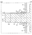
- the corner 401 on the first edge 40 side of the cover is not limited to a rounded shape, and may be, for example, a C chamfered shape or a sharp point as illustrated in FIG. It may be a shape.
Landscapes
- Physics & Mathematics (AREA)
- Electromagnetism (AREA)
- Engineering & Computer Science (AREA)
- Power Engineering (AREA)
- Magnetically Actuated Valves (AREA)
Abstract
電磁駆動部(MD)にロッド(17)が挿通している通孔(33)が形成され、ロット(17)は、通孔(33)と摺動する外壁面(42)を有する。最大突出位置に位置するロッド(17)の外壁面(42)から通孔(33)の内壁面(34)までのクリアランス(CB)は、最大引込位置に位置するロッド(17)の外壁面(42)から内壁面(34)までのクリアランス(CA)よりも小さい。これにより、引込時クリアランスが比較的大きいことによって、ロッド(17)と支持筒部(32)との摩擦力を低減可能である。また、突出時クリアランスが比較的小さいことによって、ロッド(17)の先端(44)の径方向への振れ量を低減可能である。
Description
本願は、2014年12月26日に出願された日本国特許出願第2014-263983号と、2015年10月28日に出願された日本国特許出願第2015-211824号とに基づくものであり、この開示をもってその内容を本明細書中に開示したものとする。
本開示は、電磁アクチュエータに関する。
コイルを通電するとき生じる磁力によりプランジャを軸方向へ相対移動し、プランジャと一体のロッドによって外部機器を操作可能な電磁アクチュエータが知られている。例えば特許文献1の電磁アクチュエータは、エンジンのバルブタイミング調整装置の油圧制御弁を操作する用途に用いられている。
特許文献1では、ロッドは、プランジャから軸方向へ突き出すように設けられている。ロッドの外周面は軸心に対して平行である。また、ヨークは、ロッドが挿通する通孔を有する支持部を形成している。
ところで、ロッドは、軸方向へ移動するとき支持部の通孔の内壁面と摺動する。このときの摩擦力が大きいと、ロッドおよび支持部の摩耗が増えるとともに、ロッドが移動不能となる所謂こじりが発生するおそれがある。この問題の対策としては、ロッドと通孔の内壁面とのクリアランスを大きくすることが考えられる。
一方、ロッドは、コイルの通電量が大きくなって磁力が大きくなるほど、ロッドが支持部から突き出す長さが長くなるとともに、プランジャに対して径方向にかかる力(サイドフォース)が大きくなる。そのため、ロッドが支持部から突き出す長さが長いときにロッド先端の径方向への振れ量が大きくなるという問題がある。この問題の対策としては、ロッドと通孔の内壁面とのクリアランスを小さくすることが考えられる。
したがって、上述の2つの対策は互いに相容れない。つまり、ロッドと支持部との摩擦力を小さくするためにクリアランスを大きくすると、ロッド先端の径方向への振れ量が大きくなってしまう。また、ロッド先端の径方向への振れ量を小さくするためにクリアランスを小さくすると、ロッドと支持部との摩擦力が大きくなってしまう。
本開示は、上述の点に鑑みてなされたものであり、その目的は、ロッドと支持部との摩擦力低減と、ロッド先端の径方向への振れ量低減との両立を図った電磁アクチュエータを提供することである。
本開示による電磁アクチュエータは、可動部、電磁駆動部およびロッドを備える。可動部は、所定の直線方向へ往復移動可能である。電磁駆動部は、環状のコイルを有し、コイルが通電されると、可動部を前記直線方向へ移動させる磁力を発生可能である。ロッドは、可動部から前記直線方向へ突き出すように形成され、前記直線方向の一方側に位置する最大引込位置から前記直線方向の他方側に位置する最大突出位置まで可動部と共に移動可能である。電磁駆動部は、ロッドが挿通している通孔を有する。ロッドは、通孔と摺動する外壁面を有する。
最大突出位置に位置するロッドの外壁面から通孔の内壁面までのクリアランスは、最大引込位置に位置するロッドの外壁面から内壁面までのクリアランスよりも小さい。
このように構成すれば、ロッドが引き込み側に位置するときのロッドと通孔の内壁面とのクリアランス(引込時クリアランス)を比較的大きくしつつ、ロッドが突き出し側に位置するときのロッドと通孔の内壁面とのクリアランス(突出時クリアランス)を比較的小さくすることができる。したがって、引込時クリアランスが比較的大きいことによって、ロッドと支持部との摩擦力を低減可能である。また、突出時クリアランスが比較的小さいことによって、ロッド先端の径方向への振れ量を低減可能である。つまり、ロッドと支持部との摩擦力低減と、ロッド先端の径方向への振れ量低減との両立を図ることができる。
以下、本開示の複数の実施形態を図面に基づき説明する。実施形態同士で実質的に同一の構成には同一の符号を付して説明を省略する。
[第1実施形態]
本開示の第1実施形態による電磁アクチュエータは、図1に示すエンジンのバルブタイミング調整システム80に適用されている。バルブタイミング調整システム80は、バルブタイミング調整装置81および油圧制御弁82を備えている。
本開示の第1実施形態による電磁アクチュエータは、図1に示すエンジンのバルブタイミング調整システム80に適用されている。バルブタイミング調整システム80は、バルブタイミング調整装置81および油圧制御弁82を備えている。
バルブタイミング調整装置81は、エンジンのクランク軸と同期して回転するハウジング84と、エンジンのカム軸85と一体に回転するベーンロータ86とを備え、ハウジング84とベーンロータ86との相対回転位相を変更することにより、エンジンの吸気弁または排気弁のバルブタイミングを調整可能である。ベーンロータ86は、ハウジング84内の油圧室(進角室、遅角室)の油圧の大きさに応じて当該ハウジング84に対して相対回転する。油圧室の油圧は、ベーンロータ86の中心部に設けられている油圧制御弁82により調圧される。
油圧制御弁82は、複数のポート87を有するスリーブ88と、スリーブ88内で軸方向へ移動可能なスプール89とを備えるスプール弁であり、スプール89の軸方向位置を変化させることにより各ポート87を選択的に開閉して、ハウジング84内の油圧室に作動油を供給するための油路を切り替える。電磁アクチュエータ10は、油圧制御弁82のスプール89の軸方向位置を変化させるために用いられる。
(基本構成)
先ず、電磁アクチュエータ10の基本構成を図1~図3に基づき説明する。
先ず、電磁アクチュエータ10の基本構成を図1~図3に基づき説明する。
電磁アクチュエータ10は、電磁駆動部MD、ハウジング15、ブラケット16、および、「出力軸部」としてのロッド17を備える。電磁駆動部MDは、「可動部」としてのプランジャ11、コイル12、ヨーク13、コアステータ14、および、カバー18を有する。電磁アクチュエータ10は、ロッド17を軸方向の一方側の最大引込位置から軸方向の他方側の最大突出位置までの間で移動させることにより、油圧制御弁82のスプール89の軸方向位置を変化させる。
以下、ロッド17の軸心AXと平行な方向を単に「軸方向」という。また、「軸方向の一方」とはロッド17に対してスプール89とは反対側のことを意味し、「軸方向の他方」とはロッド17に対してスプール89側のことを意味する。
プランジャ11は、中空筒状であり、磁性材料で作られている。プランジャ11は、軸心AX上に設けられており、軸方向へ往復移動可能である。軸方向は、本開示の「直線方向」に相当する。
コイル12は、樹脂製かつ筒状のボビン19の外側に巻かれた巻線から構成されている。ボビン19は、軸心AX上であってプランジャ11の外側に設けられている。外部の電源からハウジング15のコネクタ部20のターミナル21を経由して通電されることにより、コイル12は磁界を発生する。
ヨーク13は、軸心AXに沿う断面においてコイル12を取り囲むように設けられており、磁性材料で作られている。本実施形態では、ヨーク13は第1ヨーク部材22および第2ヨーク部材23から構成されている。第1ヨーク部材22は、コイル12の内側に位置する第1内側筒部24を有する。第2ヨーク部材23は、コイル12の内側に位置し、且つ、第1内側筒部24との間に磁気ギャップ25を隔てて配置された第2内側筒部26を有する。第1ヨーク部材22と第2ヨーク部材23とは、コイル12の外側で互いに接続されている。
コアステータ14は、プランジャ11の内側に位置する軸部27と、軸部27のうち軸方向の一方側の端部から第1ヨーク部材22まで突き出すフランジ部28と、を有する。
ハウジング15は、樹脂製であり、ヨーク13の一部の外側を覆うように設けられている。
ブラケット16は、ハウジング15から外側へ突き出すように形成されており、締結部材90が挿入可能な取り付け孔29を有する。
ロッド17は、プランジャ11から軸方向の他方へ突き出すように設けられており、スプール89を軸方向へ押圧可能である。ロッド17は、図1、図2に示すように軸方向の一方側に位置する最大引込位置から、図3に示すように軸方向の他方側に位置する最大突出位置まで、プランジャ11と共に移動可能である。本実施形態では、最大引込位置は、ロッド17がコアステータ14に当接する位置である。最大突出位置は、ロッド17に押されたスプール89がスリーブ88の内壁に当接する位置である。電磁アクチュエータ10がエンジンから取り外された状態であれば、ロッド17は、最大突出位置よりもさらに軸方向の他方へ移動可能である。
ロッド17が最大引込位置に位置するとき、図2に示すように、プランジャ11は第1内側筒部24の内側に位置する。ロッド17が最大突出位置に位置するとき、図3に示すように、プランジャ11は第1内側筒部24と第2内側筒部26とに跨るように位置する。
カバー18は、第2内側筒部26のうち、軸方向の他方側の端部に嵌合されて固定されている嵌合筒部30と、嵌合筒部30から径方向内側へ突き出す環状板部31と、環状板部31の内周部から軸方向の他方へ突き出す支持筒部32と、を有する。支持筒部32は、ロッド17が挿通している通孔33を有する。支持筒部32は、例えばプランジャ11に径方向の力がかかるとき等に径方向へ振れるロッド17を支持可能である。
このように構成された電磁アクチュエータ10では、コイル12が非通電のとき、プランジャ11およびロッド17は、油圧制御弁82のスプリング91によりスプール89を介して軸方向の一方へ付勢され、最大引込位置に位置させられる。
一方、コイル12が通電されると、コイル12の周りに磁界が発生し、ヨーク13およびプランジャ11により磁気回路が形成される。このとき、磁束が流れにくい磁気ギャップ25をバイパスするようにプランジャ11を移動させようと、プランジャ11には軸方向の他方へ向かう磁力が作用する。コイル12の通電量が大きいほど、すなわち磁気回路を流れる磁束が多いほど、上記磁力は大きくなる。プランジャ11、ロッド17およびスプール89の軸方向位置は、上記磁力とスプリング91による付勢力とのバランスにより決まる。電磁駆動部MDは、コイル12が通電されると、プランジャ11を軸方向へ移動させる磁力を発生可能である。
(特徴構成)
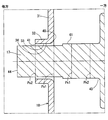
次に、電磁アクチュエータ10の特徴構成を図4、図5に基づき説明する。図4、図5では、特徴構成を分かり易くするために各部は模式的に示されており、各部の寸法、角度および寸法比は必ずしも正確なものではない。
次に、電磁アクチュエータ10の特徴構成を図4、図5に基づき説明する。図4、図5では、特徴構成を分かり易くするために各部は模式的に示されており、各部の寸法、角度および寸法比は必ずしも正確なものではない。
以下の説明において、通孔33の縁のうち、軸方向の一方側に位置する縁を第1縁40とする。また、通孔33のうち、軸方向の他方側に位置する縁を第2縁41とする。なお、第1縁40は、通孔33の軸方向の一方側の開口端を形成しており、第1開口端とも称する。また、第2縁41は、通孔33の軸方向の他方側の開口端を形成しており、第2開口端とも称する。
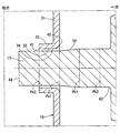
また、図4に示すようにロッド17が最大引込位置に位置するとき、ロッド17のうち、軸方向位置が第1縁40と一致する箇所を第1先端側特定箇所Ps1とし、また、ロッド17のうち、軸方向位置が第2縁41と一致する箇所を第2先端側特定箇所Ps2とする。第1先端側特定箇所Ps1および第2先端側特定箇所Ps2は、二点鎖線を用いて仮想的に示されている。
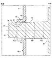
また、図5に示すように、ロッド17が最大突出位置に位置するとき、ロッド17のうち、軸方向位置が第2縁41と一致する箇所を第1基端側特定箇所Pk1とし、また、ロッド17のうち、軸方向位置が第1縁40と一致する箇所を第2基端側特定箇所Pk2とする。第1基端側特定箇所Pk1および第2基端側特定箇所Pk2は、二点鎖線を用いて仮想的に示されている。
ロッド17は、軸方向へ移動するときに通孔33の内壁面34と摺動可能な外壁面42を有する。外壁面42は、少なくとも第1基端側特定箇所Pk1から第1先端側特定箇所Ps1までの軸方向範囲において、ロッド17の基端43側から先端44側に向かって径が小さくなるテーパ状に形成されている。本実施形態では、外壁面42は、基端43から先端44までの全範囲でテーパ状である。
「ロッド17の外壁面42と通孔33の内壁面34とのクリアランス」とは、ロッド17と通孔33とが互いに同心であるとき、外壁面42から内壁面34までの間隔の最小値のことである。ロッド17が最大引込位置に位置するときのクリアランスをCAとし、ロッド17が最大突出位置に位置するときのクリアランスをCBとする。
カバー18は、板材からプレス加工により成形されている。通孔33の内壁面34は、第1縁40側から第2縁41側に向かって径が小さくなるテーパ状である。外壁面42の勾配は、通孔33の内壁面34の勾配よりも大きい。これにより、ロッド17の外壁面42から通孔33の内壁面34までのクリアランスは、ロッド17の軸方向位置にかかわらず、軸方向の一方側ほど小さくなっている。外壁面42の勾配とは、外壁面42と軸心AXとのなす角度のことである。通孔33の内壁面34の勾配とは、通孔33の内壁面34と軸心AXとのなす角度のことである。
図4、図5では、外壁面42の勾配および通孔33の内壁面34の勾配を実際よりも大きく示している。また、クリアランスを実際よりも大きく示している。
以上のように、第1縁40と第2縁41との間の軸方向範囲において、ロッド17が最大突出位置に位置するときのクリアランスCBは、最大引込位置に位置するときのクリアランスCAよりも小さい、すなわち、CA>CBの関係が成り立っている。
(比較形態)
ここで、2つの比較形態を示すことで、本実施形態の有利な点を明らかにする。
ここで、2つの比較形態を示すことで、本実施形態の有利な点を明らかにする。
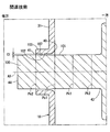
図19に模式的に示すように、第1比較形態では、ロッド100の外壁面101が軸心AXと平行な円筒面であるとともに、通孔102の内壁面107が軸心AXと平行な円筒面である。ロッド100の外壁面101と通孔102の内壁面107とのクリアランスをC1とする。クリアランスC1は、ロッド100の軸方向位置にかかわらず、本実施形態においてロッド17が最大突出位置に位置するときのクリアランスCAと同等となるように、比較的小さく設定されている。
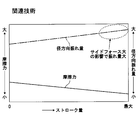
このような第1比較形態によると、図20に示すように、ロッド100のストローク量の全域においてロッド100の径方向振れ量を比較的小さく抑えることができる。しかし、外壁面101と通孔102の内壁面107との摩擦力が比較的大きくなってしまう。これにより、ロッド100および支持筒部103の摩耗が増えるとともに、ロッド100が移動不能となる所謂こじりが発生するおそれがある。
図21に模式的に示すように、第2比較形態では、ロッド105の外壁面106が軸心AXと平行な円筒面であるとともに、通孔102の内壁面107が軸心AXと平行な円筒面である。ロッド105の外壁面106と通孔102の内壁面107とのクリアランスをC2とする。クリアランスC2は、ロッド105の軸方向位置にかかわらず、本実施形態においてロッド17が最大引込位置に位置するときのクリアランスCBと同等となるように、比較的大きく設定されている。
このような第2比較形態によると、図22に示すように、ロッド105のストローク量の全域において外壁面106と通孔102の内壁面107との摩擦力を比較的小さく抑えることができる。しかし、ロッド105の径方向振れ量が比較的大きくなってしまう。特に、ロッド105のストローク量が大きいとき、磁力増大の影響でプランジャに対する径方向の力(サイドフォース)が大きくなり、ロッド105が径方向へ大きく振れてしまう。
一方、第1実施形態では、ロッド17が最大突出位置に位置するときのクリアランスCAは第1比較形態におけるクリアランスC1と同等であるとともに、ロッド17が最大引込位置に位置するときのクリアランスCBは第2比較形態におけるクリアランスC2と同等である。そのため、図6に示すように、ロッド17のストローク量の全域において、ロッド17の径方向振れ量を比較的小さく抑えつつ、外壁面42と通孔33の内壁面34との摩擦力を比較的小さく抑えることができる。
(効果)
以上説明したように、第1実施形態では、ロッド17は、少なくとも第1基端側特定箇所Pk1から第1先端側特定箇所Ps1までの軸方向範囲において、ロッド17の基端43側から先端44側に向かって径が小さくなるテーパ状の外壁面42を有する。これにより、ロッド17が最大突出位置に位置するときのクリアランスCBは、ロッド17が最大引込位置に位置するときのクリアランスCAよりも小さい。
以上説明したように、第1実施形態では、ロッド17は、少なくとも第1基端側特定箇所Pk1から第1先端側特定箇所Ps1までの軸方向範囲において、ロッド17の基端43側から先端44側に向かって径が小さくなるテーパ状の外壁面42を有する。これにより、ロッド17が最大突出位置に位置するときのクリアランスCBは、ロッド17が最大引込位置に位置するときのクリアランスCAよりも小さい。
このように構成すれば、ロッド17が引き込み側に位置するときのロッド17と通孔33の内壁面34とのクリアランス(引込時クリアランス)を比較的大きくしつつ、ロッド17が突き出し側に位置するときのロッド17と通孔33の内壁面34とのクリアランス(突出時クリアランス)を比較的小さくすることができる。したがって、引込時クリアランスが比較的大きいことによって、ロッド17と支持筒部32との摩擦力を低減可能である。また、突出時クリアランスが比較的小さいことによって、ロッド17の先端44の径方向への振れ量を低減可能である。つまり、ロッド17と支持筒部32との摩擦力低減と、ロッド17の先端44の径方向への振れ量低減との両立を図ることができる。
また、第1実施形態では、外壁面42は、少なくとも第1基端側特定箇所Pk1から第2先端側特定箇所Ps2までの軸方向範囲においてテーパ状である。
このように構成すれば、ロッド17のうち、第1先端側特定箇所Ps1から先端44側の外周面が軸方向と平行である場合と比べて、引込時クリアランスが大きくなる。したがって、ロッド17と支持筒部32との摩擦力を一層低減可能である。
また、第1実施形態では、外壁面42は、少なくとも第2基端側特定箇所Pk2から第1先端側特定箇所Ps1までの軸方向範囲においてテーパ状である。
このように構成すれば、ロッド17のうち、第1基端側特定箇所Pk1から基端43側の外周面が軸方向と平行である場合と比べて、突出時クリアランスが小さくなる。したがって、ロッド17の先端44の径方向への振れ量を一層低減可能である。
また、第1実施形態では、通孔33の内壁面34は、第1縁40側から第2縁41側に向かって径が小さくなるテーパ状である。外壁面42の勾配は、通孔33の内壁面34の勾配よりも大きい。
このように構成すれば、外壁面42と通孔33の内壁面34とのクリアランスは、ロッド17の軸方向位置にかかわらず、軸方向の一方側ほど狭くなる。したがって、図7に示すように、ロッド17が径方向へ振れたときに外壁面42と通孔33の内壁面34とが面接触するように構成することができる。
[第2実施形態]
本開示の第2実施形態では、図8に示すように、外壁面50は、第1基端側特定箇所Pk1から第1先端側特定箇所Ps1までの軸方向範囲においてテーパ状である。外壁面50は、第1先端側特定箇所Ps1から先端44側が軸方向と平行であるとともに、第1基端側特定箇所Pk1から基端43側が軸方向と平行である。このように外壁面50の一部がテーパ状であっても、第1、第2比較形態と比べると、ロッド17と支持筒部32との摩擦力低減とロッド17の先端44の径方向への振れ量低減との両立を図ることができる。
本開示の第2実施形態では、図8に示すように、外壁面50は、第1基端側特定箇所Pk1から第1先端側特定箇所Ps1までの軸方向範囲においてテーパ状である。外壁面50は、第1先端側特定箇所Ps1から先端44側が軸方向と平行であるとともに、第1基端側特定箇所Pk1から基端43側が軸方向と平行である。このように外壁面50の一部がテーパ状であっても、第1、第2比較形態と比べると、ロッド17と支持筒部32との摩擦力低減とロッド17の先端44の径方向への振れ量低減との両立を図ることができる。
[第3実施形態]
本開示の第3実施形態では、図9に示すように、基端43側から先端44側に向かって、所定の間隔で段階的にロッド17の径が小さくなるように、外壁面60が段付き形状に形成されている。ロッド17の径が小さくなる間隔は、任意に設定してもよい。本実施形態では、外壁面60は、基端43側から先端44側までの全範囲に対して階段状である。このような階段状のロッドにおいても、ロッド17が最大引込位置に位置するときのクリアランスCAよりも、ロッド17が最大突出位置に位置するときのクリアランスCBよりも小さくなる。したがって、第1実施形態と同様の効果を奏する。
本開示の第3実施形態では、図9に示すように、基端43側から先端44側に向かって、所定の間隔で段階的にロッド17の径が小さくなるように、外壁面60が段付き形状に形成されている。ロッド17の径が小さくなる間隔は、任意に設定してもよい。本実施形態では、外壁面60は、基端43側から先端44側までの全範囲に対して階段状である。このような階段状のロッドにおいても、ロッド17が最大引込位置に位置するときのクリアランスCAよりも、ロッド17が最大突出位置に位置するときのクリアランスCBよりも小さくなる。したがって、第1実施形態と同様の効果を奏する。
[第4実施形態]
本開示の第4実施形態では、図10に示すように、第1基端側特定箇所Pk1から第2基端側特定箇所Pk2までの軸方向範囲において、ロッド17は径方向外側に突出する突起71を有する。ロッド17が突起71を有することで、外壁面70は径方向外側に突出した突出面72を含む。外壁面70が突出面72を含むことにより、ロッド17が最大引込位置に位置するときのクリアランスCAよりも、ロッド17が最大突出位置に位置するときのクリアランスCBよりも小さくなる。したがって、第4実施形態においても、第1実施形態と同様の効果を奏する。
本開示の第4実施形態では、図10に示すように、第1基端側特定箇所Pk1から第2基端側特定箇所Pk2までの軸方向範囲において、ロッド17は径方向外側に突出する突起71を有する。ロッド17が突起71を有することで、外壁面70は径方向外側に突出した突出面72を含む。外壁面70が突出面72を含むことにより、ロッド17が最大引込位置に位置するときのクリアランスCAよりも、ロッド17が最大突出位置に位置するときのクリアランスCBよりも小さくなる。したがって、第4実施形態においても、第1実施形態と同様の効果を奏する。
[他の実施形態]
第2実施形態の思想を共有する他の実施形態では、図11に示すように、第2基端側特定箇所Pk2から第1基端側特定箇所Pk1までの軸方向範囲において、外壁面51を基端43側から先端44側に向かって径が小さくなるテーパ状としてもよい。
第2実施形態の思想を共有する他の実施形態では、図11に示すように、第2基端側特定箇所Pk2から第1基端側特定箇所Pk1までの軸方向範囲において、外壁面51を基端43側から先端44側に向かって径が小さくなるテーパ状としてもよい。
図12に示すように、第1先端側特定箇所Ps1から第2先端側特定箇所Ps2までの軸方向範囲において、外壁面52を基端43側から先端44側に向かって径が小さくなるテーパ状としてもよい。
図13に示すように、第2基端側特定箇所Pk2から第1先端側特定箇所Ps1までの軸方向範囲において、外壁面53を基端43側から先端44側に向かって径が小さくなるテーパ状としてもよい。
図14に示すように、第1基端側特定箇所Pk1から第2先端側特定箇所Ps2までの軸方向範囲において、外壁面54を基端43側から先端44側に向かって径が小さくなるテーパ状としてもよい。
図15に示すように、第2基端側特定箇所Pk2から第2先端側特定箇所Ps2までの軸方向範囲において、外壁面55を基端43側から先端44側に向かって径が小さくなるテーパ状としてもよい。
図16に示すように、第1先端側特定箇所Ps1と第2先端側特定箇所Ps2との間Ps21から第1基端側特定箇所Pk1と第2基端側特定箇所Pk2との間Pk12までの軸方向範囲において、外壁面56を基端43側から先端44側に向かって径が小さくなるテーパ状としてもよい。
また、第1先端側特定箇所と第2先端側特定箇所との間から第1基端側特定箇所と第1先端端側特定箇所との間までの軸方向範囲において、外壁面を基端側から先端側に向かって径が小さくなるテーパ状としてもよい。さらに第1基端側特定箇所と第1先端端側特定箇所との間から第1基端側特定箇所と第2基端側特定箇所との間までの軸方向範囲において、外壁面を基端側から先端側に向かって径が小さくなるテーパ状としてもよい。
第3実施形態の思想を共有する他の実施形態では、図17に示すように、第1先端側特定箇所Ps1から第2基端側特定箇所Pk2までの軸方向範囲の一部において、ロッド17の外壁面61を段になっている段付き形状としてもよい。第1実施形態と同様の効果を奏する。
第4実施形態の思想を共有する他の実施形態では、ロッドは、軸および軸に嵌合するリングを有し、突起はリングから構成されてもよい。
本開示の他の実施形態では、カバーを複数のカバー体に分割し、可動部とは別の駆動部を用いて、複数のカバー体を径方向内側に動作可能にする。ロッドが最大引込位置から最大突出位置に摺動するとき、カバーをロッドに接近させる。ロッドが摺動するときにカバーを接近させることで、ロッドが最大突出位置に位置するときのクリアランスを、ロッド最大引込位置に位置するときのクリアランスよりも小さくすることができる。
本開示の他の実施形態では、ロッドは、プランジャと同一部材から構成されてもよい。
本開示の他の実施形態では、カバーは、プレス加工による成形品に限らず、例えば切削加工による成形品であってもよい。
本開示の他の実施形態では、カバーの通孔の内壁面は、軸方向と平行な円筒面であってもよい。
本開示の他の実施形態では、カバーは、ヨークと同一部材から構成されてもよい。
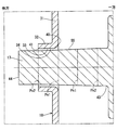
本開示の他の実施形態では、カバーの第1縁40側の角部401は、丸みを帯びている形状に限らず、例えばC面取り形状であってもよいし、図18に示すように尖鋭形状であってもよい。
本開示は、上述した実施形態に限定されるものではなく、開示の趣旨を逸脱しない範囲で種々の形態で実施可能である。
Claims (7)
- 所定の直線方向へ往復移動可能な可動部(11)と、
環状のコイル(12)を有し、前記コイル(12)が通電されると、前記可動部(11)を前記直線方向へ移動させる磁力を発生可能な電磁駆動部(MD)と、
前記可動部(11)から前記直線方向へ突き出すように設けられ、前記直線方向の一方側に位置する最大引込位置から前記直線方向の他方側に位置する最大突出位置まで前記可動部(11)と共に移動可能なロッド(17)と、
を備え、
前記電磁駆動部(MD)は、前記ロッド(17)が挿通している通孔(33)を有し、
前記ロッド(17)は、前記通孔(33)と摺動可能な外壁面(42、50~56、60~61、70)を有し、
前記最大突出位置に位置する前記ロッド(17)の前記外壁面(42、50、60、70)から前記通孔(33)の内壁面(34)までのクリアランス(CB)は、前記最大引込位置に位置する前記ロッド(17)の前記外壁面(42、50~56、60~61、70)から前記内壁面(34)までのクリアランス(CA)よりも小さい電磁アクチュエータ。 - 前記通孔(33)のうち、前記直線方向の一方側に位置する縁を第1縁(40)とし、
前記通孔(33)のうち、前記直線方向の他方側に位置する縁を第2縁(41)とし、
前記ロッド(17)が前記最大引込位置に位置するとき、前記ロッド(17)のうち、軸方向位置が前記第1縁(40)と一致する箇所を第1先端側特定箇所(Ps1)とし、
前記ロッド(17)が前記最大引込位置に位置するとき、前記ロッド(17)のうち、軸方向位置が前記第2縁(41)と一致する箇所を第2先端側特定箇所(Ps2)とし、
前記ロッド(17)が前記最大突出位置に位置するとき、前記ロッド(17)のうち、軸方向位置が前記第2縁(41)と一致する箇所を第1基端側特定箇所(Pk1)とし、
前記ロッド(17)が前記最大突出位置に位置するとき、前記ロッド(17)のうち、軸方向位置が前記第1縁(40)と一致する箇所を第2基端側特定箇所(Pk2)とすると、
前記外壁面(42、50、53~56)は、少なくとも前記第1基端側特定箇所(Pk1)から前記第1先端側特定箇所(Ps1)までの軸方向範囲において、前記ロッド(17)の基端(43)側から先端(44)側に向かって径が小さくなるテーパ状である請求項1に記載の電磁アクチュエータ。 - 前記外壁面(42、53、55~56)は、少なくとも前記第2基端側特定箇所(Pk2)から前記第1基端側特定箇所(Pk1)までの軸方向範囲において、前記基端(43)側から前記先端(44)側に向かって径が小さくなるテーパ状である請求項2に記載の電磁アクチュエータ。
- 前記外壁面(42、54~56)は、少なくとも前記第1先端側特定箇所(Ps1)から前記第2先端側特定箇所(Ps2)までの軸方向範囲において、前記基端(43)側から前記先端(44)側に向かって径が小さくなるテーパ状である請求項2または3に記載の電磁アクチュエータ。
- 前記外壁面(42)は、前記ロッド(17)の基端(43)から先端(44)に向かって径が小さくなるテーパ状である請求項1に記載の電磁アクチュエータ。
- 前記外壁面(60~61)は、前記ロッド(17)の基端(43)から先端(44)に向かって、径が段階的に小さくなる段付き形状である請求項1に記載の電磁アクチュエータ。
- 前記通孔(33)のうち、前記直線方向の一方側に位置する縁を第1縁(40)とし、
前記通孔(33)のうち、前記直線方向の他方側に位置する縁を第2縁(41)とし、
前記ロッド(17)が前記最大突出位置に位置するとき、前記ロッド(17)のうち、軸方向位置が前記第2縁(41)と一致する箇所を第1基端側特定箇所(Pk1)とし、
前記ロッド(17)が前記最大突出位置に位置するとき、前記ロッド(17)のうち、軸方向位置が前記第1縁(40)と一致する箇所を第2基端側特定箇所(Pk2)とすると、
前記外壁面(70)は、第2基端側特定箇所(Pk2)から第1基端側特定箇所(Pk1)までの軸方向範囲において、少なくとも1つの突出面(72)を含む請求項1に記載の電磁アクチュエータ。
Priority Applications (3)
| Application Number | Priority Date | Filing Date | Title |
|---|---|---|---|
| DE112015005777.3T DE112015005777T5 (de) | 2014-12-26 | 2015-12-17 | Elektromagnetischer Aktuator |
| US15/526,452 US10283245B2 (en) | 2014-12-26 | 2015-12-17 | Electromagnetic actuator |
| CN201580064846.4A CN107004488B (zh) | 2014-12-26 | 2015-12-17 | 电磁促动器 |
Applications Claiming Priority (4)
| Application Number | Priority Date | Filing Date | Title |
|---|---|---|---|
| JP2014-263983 | 2014-12-26 | ||
| JP2014263983 | 2014-12-26 | ||
| JP2015-211824 | 2015-10-28 | ||
| JP2015211824A JP6531617B2 (ja) | 2014-12-26 | 2015-10-28 | 電磁アクチュエータ |
Publications (1)
| Publication Number | Publication Date |
|---|---|
| WO2016103662A1 true WO2016103662A1 (ja) | 2016-06-30 |
Family
ID=56149725
Family Applications (1)
| Application Number | Title | Priority Date | Filing Date |
|---|---|---|---|
| PCT/JP2015/006301 Ceased WO2016103662A1 (ja) | 2014-12-26 | 2015-12-17 | 電磁アクチュエータ |
Country Status (1)
| Country | Link |
|---|---|
| WO (1) | WO2016103662A1 (ja) |
Citations (2)
| Publication number | Priority date | Publication date | Assignee | Title |
|---|---|---|---|---|
| JPH1162825A (ja) * | 1997-08-27 | 1999-03-05 | Toyota Autom Loom Works Ltd | 可変容量型圧縮機用制御弁 |
| JP2012112421A (ja) * | 2010-11-24 | 2012-06-14 | Toyota Motor Corp | 電磁式リニア弁 |
-
2015
- 2015-12-17 WO PCT/JP2015/006301 patent/WO2016103662A1/ja not_active Ceased
Patent Citations (2)
| Publication number | Priority date | Publication date | Assignee | Title |
|---|---|---|---|---|
| JPH1162825A (ja) * | 1997-08-27 | 1999-03-05 | Toyota Autom Loom Works Ltd | 可変容量型圧縮機用制御弁 |
| JP2012112421A (ja) * | 2010-11-24 | 2012-06-14 | Toyota Motor Corp | 電磁式リニア弁 |
Similar Documents
| Publication | Publication Date | Title |
|---|---|---|
| US8928440B2 (en) | Linear solenoid | |
| KR101512871B1 (ko) | 솔레노이드 밸브의 전자기 액추에이팅 유닛 및 이의 제조 방법 | |
| JP6311617B2 (ja) | 電磁アクチュエータ | |
| WO2012039293A1 (ja) | リニアアクチュエータ | |
| JP5862503B2 (ja) | リニアソレノイド | |
| KR101900587B1 (ko) | 폴 피스와 플럭스 슬리브의 정렬불량에 강한 솔레노이드 | |
| JP6518400B2 (ja) | ソレノイド | |
| WO2013191000A1 (ja) | リニアアクチュエータ及びリニアアクチュエータの溝加工方法 | |
| JP6531617B2 (ja) | 電磁アクチュエータ | |
| JP6314847B2 (ja) | 電磁アクチュエータ | |
| US7777603B2 (en) | Armature and solenoid assembly | |
| WO2020226101A1 (ja) | ソレノイドバルブ | |
| WO2016103662A1 (ja) | 電磁アクチュエータ | |
| JP5786846B2 (ja) | ソレノイド | |
| JP5720637B2 (ja) | リニアソレノイド | |
| CN104968900A (zh) | 带有密封件的滑动凸轮促动器 | |
| CN110326065B (zh) | 电磁式线性致动器 | |
| JP6669040B2 (ja) | 電磁アクチュエータ | |
| JP5720639B2 (ja) | リニアソレノイド | |
| JP5720638B2 (ja) | リニアソレノイド | |
| US20210343461A1 (en) | Electromagnetic actuator | |
| US9627123B2 (en) | Solenoid | |
| JP6163337B2 (ja) | ソレノイドアクチュエータ | |
| JP5955763B2 (ja) | 弁構造 | |
| JP2016079847A (ja) | 流体リニア加圧機 |
Legal Events
| Date | Code | Title | Description |
|---|---|---|---|
| 121 | Ep: the epo has been informed by wipo that ep was designated in this application |
Ref document number: 15872235 Country of ref document: EP Kind code of ref document: A1 |
|
| WWE | Wipo information: entry into national phase |
Ref document number: 15526452 Country of ref document: US |
|
| WWE | Wipo information: entry into national phase |
Ref document number: 112015005777 Country of ref document: DE |
|
| 122 | Ep: pct application non-entry in european phase |
Ref document number: 15872235 Country of ref document: EP Kind code of ref document: A1 |