WO2016103661A1 - 車両用通信端末 - Google Patents
車両用通信端末 Download PDFInfo
- Publication number
- WO2016103661A1 WO2016103661A1 PCT/JP2015/006300 JP2015006300W WO2016103661A1 WO 2016103661 A1 WO2016103661 A1 WO 2016103661A1 JP 2015006300 W JP2015006300 W JP 2015006300W WO 2016103661 A1 WO2016103661 A1 WO 2016103661A1
- Authority
- WO
- WIPO (PCT)
- Prior art keywords
- terminal
- service
- vehicle
- communication
- roadside
- Prior art date
- Legal status (The legal status is an assumption and is not a legal conclusion. Google has not performed a legal analysis and makes no representation as to the accuracy of the status listed.)
- Ceased
Links
Images



Classifications
-
- H—ELECTRICITY
- H04—ELECTRIC COMMUNICATION TECHNIQUE
- H04W—WIRELESS COMMUNICATION NETWORKS
- H04W4/00—Services specially adapted for wireless communication networks; Facilities therefor
- H04W4/02—Services making use of location information
- H04W4/025—Services making use of location information using location based information parameters
- H04W4/027—Services making use of location information using location based information parameters using movement velocity, acceleration information
-
- H—ELECTRICITY
- H04—ELECTRIC COMMUNICATION TECHNIQUE
- H04W—WIRELESS COMMUNICATION NETWORKS
- H04W4/00—Services specially adapted for wireless communication networks; Facilities therefor
- H04W4/02—Services making use of location information
- H04W4/029—Location-based management or tracking services
-
- H—ELECTRICITY
- H04—ELECTRIC COMMUNICATION TECHNIQUE
- H04W—WIRELESS COMMUNICATION NETWORKS
- H04W4/00—Services specially adapted for wireless communication networks; Facilities therefor
- H04W4/30—Services specially adapted for particular environments, situations or purposes
- H04W4/40—Services specially adapted for particular environments, situations or purposes for vehicles, e.g. vehicle-to-pedestrians [V2P]
-
- H—ELECTRICITY
- H04—ELECTRIC COMMUNICATION TECHNIQUE
- H04W—WIRELESS COMMUNICATION NETWORKS
- H04W84/00—Network topologies
- H04W84/18—Self-organising networks, e.g. ad-hoc networks or sensor networks
Definitions
- the present disclosure relates to a vehicle communication terminal that performs wireless communication with at least one of a communication terminal installed on a road and a communication terminal mounted on another vehicle.
- Non-Patent Document 1 includes a vehicle communication terminal (hereinafter referred to as an in-vehicle terminal) mounted on a vehicle, an in-vehicle terminal mounted on another vehicle, and a communication terminal (hereinafter referred to as a roadside device) installed along a road.
- a vehicle communication terminal hereinafter referred to as an in-vehicle terminal
- a communication terminal hereinafter referred to as a roadside device
- an in-vehicle terminal and a communication terminal managed by a service provider that provides a predetermined service, such as a roadside device, are referred to as a control channel and a service channel. Communication is performed using two types of channels.
- the service channel is a channel used for transmission / reception of information for providing (and enjoying) service.
- the control channel is a channel used for delivering information (WSA: Wave Service Advertisement) for starting communication using the service channel between the in-vehicle terminal and the service providing terminal.
- WSA Wave Service Advertisement
- a plurality of frequencies used as service channels are prepared, and the service type information indicating the type of service provided by the WSA distribution source and the service channel (that is, frequency) used for providing the service are specified in the WSA. Channel information is included.
- the service providing terminal sequentially broadcasts the WSA corresponding to the service provided by the self terminal using the control channel. For example, when there is a response from the in-vehicle terminal to the WSA, the service providing terminal and the service providing terminal Start communication using the channel.
- the in-vehicle terminal When the in-vehicle terminal receives the WSA, the in-vehicle terminal performs processing according to the service type information included in the WSA. Specifically, referring to the received service type information of the WSA, if the type of service provided by the WSA distribution source is a type of service that can be used in the terminal itself, the received WSA is indicated in the received WSA. Open a service channel.
- opening a service channel refers to starting communication using a predetermined service channel with the WSA distribution source.
- the type of service provided by the received WSA distribution source is not the type of service available to the terminal itself, the service channel is not opened.
- the area where the service providing terminal distributes WSA is usually formed so as to coincide with an area through which a vehicle (strictly speaking, an in-vehicle terminal) to be provided with the service passes.
- the WSA distribution area by the service providing terminal is not necessarily within the area through which the vehicle to be provided with the service passes.
- the WSA distribution area may be formed so as to include an area where a vehicle that is not a service provision target travels.
- the in-vehicle terminal may receive a WSA corresponding to an unnecessary service even if it can be used by the own terminal.
- WSA corresponding to a service unnecessary for the terminal itself is, for example, a service for a vehicle traveling in a lane (for example, an opposite lane) different from the lane in which the vehicle in which the terminal is mounted (hereinafter, the host vehicle) is traveling. This corresponds to WSA distributed from a service providing terminal to be provided.
- the service type information included in the WSA is referred to, and when the service type is a service that can be used in the own terminal, the service channel of the frequency indicated in the WSA Open.
- the in-vehicle terminal receives a WSA corresponding to a service that is originally unnecessary for the own terminal, if the type of service indicated in the WSA is a service that can be used in the own terminal, The service channel indicated by the WSA is opened. That is, it is assumed that the in-vehicle terminal opens a service channel corresponding to a service unnecessary for the terminal itself.
- One of the objects of the present disclosure is to provide a vehicle communication terminal that can suppress the start of communication using a service channel with a service providing terminal that provides a service unnecessary for the terminal itself.
- a vehicle communication terminal includes a control channel used for communication connection control and a plurality of types of service channels that are different from the control channel and are allocated for providing a service. And a wireless communication unit that performs wireless communication with a service providing terminal that provides a predetermined service by using any one of them, and a wireless communication control unit that controls the operation of the wireless communication unit A communication terminal, wherein the wireless communication unit transmits service type information indicating a type of service provided by the service providing terminal, transmitted from the service providing terminal using the control channel, and the service providing terminal among the plurality of service channels Service channel information for specifying a service channel to be used for communication with its own terminal.
- the vehicle communication terminal further receives a reception intensity of a signal transmitted from the service providing terminal and received by the wireless communication unit; and a wireless communication unit
- a signal corresponding to the service start information is received from the service providing terminal, the reception strength obtained by the reception strength obtaining unit for the received signal and the service providing source of the received signal
- the transmitting terminal is a service providing terminal for which the own terminal is a service providing target, based on at least one of the degree of change in reception intensity of a signal received from a terminal (hereinafter referred to as a transmitting terminal)
- the wireless communication control unit is a service providing terminal whose service is targeted for providing the own terminal by the transmitting terminal determining unit. Until it is determined that that, the transmitting terminal does not initiate the communication using the service channel that is specified in the service channel information included in the service start information transmitted from the transmitting terminal.
- the reception strength acquisition unit acquires the reception strength of the signal transmitted from the service providing terminal
- the transmission terminal determination unit receives the magnitude of the reception strength and the signal transmitted from the transmission terminal. Based on at least one of the degrees of intensity change, it is determined whether or not the transmitting terminal is a service providing terminal for which the own terminal is a service providing target.
- the degree of change in reception strength may be the degree of change in reception strength with respect to the distance traveled by the vehicle communication terminal, or the degree of change in reception strength over time. Good. This is because the vehicle communication terminal is used in a vehicle, and therefore, the relative position with respect to the service providing terminal is expected to change with the passage of time. That is, even if the degree of change in reception intensity is the degree of change per fixed time, it indirectly represents the degree of change in reception intensity with respect to the travel distance of the vehicle communication terminal.
- the vehicle communication terminal receives a signal from a service providing terminal (hereinafter referred to as the own terminal target terminal) whose service is the own terminal. And when receiving a signal from a service providing terminal that does not target its own terminal (hereinafter referred to as its own non-target terminal) as the vehicle communication terminal moves The difference in intensity change and the difference in reception intensity will be briefly described.
- the own terminal target terminal here corresponds to, for example, a service providing terminal that provides a service to a vehicle traveling in a lane in which the vehicle on which the own terminal is mounted (hereinafter, the own vehicle) travels.
- the self-terminal non-target terminal corresponds to a service providing terminal that provides a service to a vehicle traveling in a lane (for example, an oncoming lane) different from the lane in which the host vehicle is traveling.
- the change in the reception intensity accompanying the movement is compared to the change when receiving the signal from the target terminal of the own terminal, It is moderate and its size changes in a relatively small area.
- the own terminal non-target terminal is provided at a position farther from the lane in which the host vehicle travels than the own terminal target terminal.
- the signal strength of the radio signal is attenuated as it propagates through space, so even if the signal transmitted by the non-target terminal of the terminal reaches the lane in which the host vehicle travels, a relatively long distance is required. Since it propagates, there is a high possibility that it is sufficiently attenuated.
- the subject terminal target terminal is provided near the lane in which the subject vehicle travels, and transmits a signal to the lane in which the subject vehicle travels. For this reason, the vehicle communication terminal receives a relatively strong signal.
- the degree of change in received strength in the process in which the vehicle communication terminal approaches and leaves the own terminal target terminal is greater than the degree of change in received strength in the process in which the vehicle communication terminal approaches and leaves the own terminal non-target terminal. Also grows.
- the degree of increase in reception strength in the process in which the vehicle communication terminal approaches the target terminal target terminal increases the reception strength accompanying the movement of the vehicle communication terminal in the process of approaching the non-target terminal. Greater than degree.
- the degree of decrease in received intensity in the process of leaving the vehicle communication terminal from the own terminal target terminal is greater than the degree of decrease in reception intensity in the process of leaving the vehicle communication terminal from the non-target terminal.
- the reception intensity when the vehicle communication terminal is sufficiently close to the own terminal target terminal is sufficiently large to be distinguishable from the case where the vehicle terminal is closest to the own terminal non-target terminal.
- the transmission terminal determination unit can determine whether or not the service providing terminal that is currently transmitting the service start information received is the own terminal target roadside device based on these indicators. it can.
- the transmitting terminal determining unit determines that the transmitting terminal is a service providing terminal for which the own terminal is a service providing target. Until this is done, communication using the service channel is not started.
- a service providing terminal that is not determined to be a subject terminal is relatively likely to be a service providing terminal for providing a service to a vehicle traveling in a lane different from the lane in which the host vehicle is traveling.
- the service provided by the service providing terminal is an unnecessary service for the terminal itself.
- the vehicle communication terminal can suppress the start of communication using a service channel with a service providing terminal that provides a service unnecessary for the terminal itself.
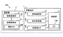
- FIG. 1 is a block diagram showing a schematic configuration of a mobile communication system according to an embodiment.
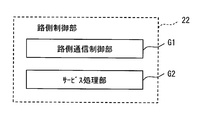
- FIG. 2 is a block diagram illustrating an example of a schematic configuration of the roadside control unit.
- FIG. 3 is a diagram illustrating an example of a schematic configuration of WSA.
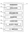
- FIG. 4 is a block diagram illustrating a schematic configuration of a control unit included in the vehicle-mounted device.
- FIG. 5 is a block diagram for explaining a schematic configuration of a peripheral roadside machine list.
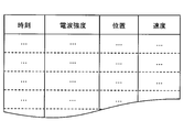
- FIG. 6 is a block diagram for explaining the configuration of reception history data.
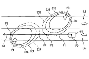
- FIG. 7 is a diagram for explaining the determination principle of the transmission terminal determination unit.
- FIG. 1 is a block diagram showing a schematic configuration of a mobile communication system according to an embodiment.
- FIG. 2 is a block diagram illustrating an example of a schematic configuration of the roadside control unit.
- FIG. 3 is a diagram illustrating an example of a schematic configuration of WSA.
- FIG. 4 is a block diagram illustrating a
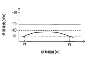
- FIG. 8 is a diagram for explaining the transition of reception intensity accompanying movement when receiving a signal transmitted from a roadside machine that is targeted for providing a vehicle traveling in an oncoming lane.
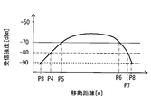
- FIG. 9 is a diagram for explaining the transition of the reception intensity accompanying movement when receiving a signal transmitted from a roadside machine that is targeted for providing a vehicle on which the host vehicle is traveling.
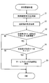
- FIG. 10 is a flowchart for explaining reception-related processing performed by the control unit.
- FIG. 11 is a diagram for explaining the effect of determining whether or not the transmitting terminal is a roadside device that is subject to service provision by comparing the reception intensity with the intensity threshold.
- FIG. 12 is a diagram illustrating an example of a schematic configuration of a WSA in the first modification.
- FIG. 13 is a block diagram illustrating an example of a schematic configuration of a control unit according to the sixth modification.
- FIG. 1 is a diagram showing an example of a schematic configuration of a mobile communication system 100 according to the present embodiment.
- the mobile communication system 100 includes a roadside device 2 that is a communication terminal installed along a road and an in-vehicle device 1 that is a communication terminal used in a vehicle.
- the vehicle-mounted device 1 corresponds to a vehicle communication terminal.
- FIG. 1 only one roadside device 2 is shown for convenience, but a plurality of mobile communication systems 100 may be provided.
- the vehicle-mounted device 1 is mounted on each of a plurality of vehicles. Therefore, the mobile communication system 100 as a whole includes a plurality of vehicle-mounted devices 1.
- the vehicle-mounted device 1 and the roadside device 2 are not distinguished, they are simply referred to as communication terminals.
- the vehicle-mounted device 1 and the roadside device 2 perform communication (so-called road-to-vehicle communication) based on the WAVE (Wireless Access in Vehicular Environment) standard described in Non-Patent Document 1. More specifically, the road-to-vehicle communication between the vehicle-mounted device 1 and the roadside device 2 is performed using a control channel and any one of a plurality of service channels.
- the control channel is a channel on which broadcast communication is performed.
- the control channel is used, for example, for the roadside device 2 to transmit a WSA (Wave Service Advertisement) that is a message for starting communication using the predetermined service channel with the vehicle-mounted device 1 existing in the vicinity of the terminal. . Details of WSA will be described later.
- WSA Wide Service Advertisement
- the periphery of the communication terminal refers to an area where the communication terminal can perform wireless communication (hereinafter referred to as a wireless communication area).
- the wireless communication area of each communication terminal may be designed as appropriate.
- the service channel is a channel used for communication with a specific communication terminal. That is, in the service channel, unicast or multicast communication is performed.
- the service channel is used for transmission / reception of information related to provision (and enjoyment) of a predetermined service by the vehicle-mounted device 1 and the roadside device 2, for example.
- the mobile communication system 100 includes four service channels, which are referred to as a first service channel, a second service channel, a third service channel, and a fourth service channel, respectively.
- the control channel and the plurality of service channels are all realized using different frequencies.
- the control channel and the various service channels are all frequencies belonging to the 5.8 GHz band and the 5.9 GHz band.
- each service channel may be distinguished by a number (channel number) set for the service channel.
- the service channel and the control channel may be realized by using a frequency belonging to the 2.4 GHz band in addition to the 5.8 GHz band and the 5.9 GHz band, or using a frequency belonging to another frequency band (700 MHz). May be realized.
- each channel may be implemented using time division multiplexing techniques at one or more frequencies.
- the communication between the vehicle-mounted device 1 and the roadside device 2 is mainly referred to.
- the vehicle-mounted device 1 may perform inter-vehicle communication in conformity with the other vehicle-mounted device 1 and the WAVE standard. Good.
- An identification code (referred to as a terminal ID) for identifying a plurality of communication terminals is set in each of the communication terminals (that is, the vehicle-mounted device 1 and the roadside device 2) included in the mobile communication system 100.
- the data transmitted from each communication terminal includes the terminal ID of the transmission terminal, and the communication terminal that has received the data can identify the transmission terminal by the terminal ID included in the data. .
- summary and the structure of the roadside machine 2 and the vehicle equipment 1 are demonstrated.
- the roadside device 2 performs road-to-vehicle communication with the vehicle-mounted device 1 existing in the wireless communication area formed by the roadside device 2, and transmits various information to the vehicle-mounted device 1 or obtains various information from the vehicle-mounted device 1. To implement a predetermined service.
- This roadside machine 2 corresponds to an example of a service providing terminal.
- the roadside machine 2 only needs to be provided at a position suitable for the service provided by the roadside machine 2.
- a specific facility for example, on the way of an intersection or a road (so-called link) connecting the intersection and the intersection
- the wireless communication area of the roadside device 2 is formed so as to include a region through which a vehicle to which the roadside device 2 should provide a service can pass, and not to include a region through which a vehicle that should not be a service target passes. It is preferred that
- the roadside device 2 provides a service (referred to as a traffic information transmission service) for transmitting information (referred to as driving support information) for assisting the driver's recognition / judgment to the traffic situation around the roadside device 2.
- a traffic information transmission service for transmitting information (referred to as driving support information) for assisting the driver's recognition / judgment to the traffic situation around the roadside device 2.
- driving support information represents traffic jam information around the roadside machine, presence / absence of presence of vehicles, pedestrians, obstacles, and the like in the area around the roadside machine where the driver is blind spot.
- the roadside machine periphery may be a range designed as appropriate based on the position of the roadside machine.
- the wireless communication area is formed so as not to cover other lanes. It is preferable.
- the roadside device 2 provides a service (payment service) that performs payment for delivery of services or goods in a predetermined facility, a desired wireless communication area is formed near the entrance of the facility. Should just be installed.
- a service payment service
- Facilities that provide a settlement service using the roadside machine 2 include restaurants, banks, laundry stores, various stores such as gas stations, and paid parking lots.
- the roadside machine 2 is provided at each of the entrance and exit of the toll road, for example, and charges the vehicle using the toll road by road-to-vehicle communication according to the use contents (traveling section, time zone, etc.) It may be used for the purpose of implementing.
- the roadside device 2 may provide a service for diagnosing an abnormality of the vehicle-mounted device 1 or the vehicle on which the vehicle-mounted device 1 is mounted.
- the vehicle-mounted device 1 and the vehicle on which the vehicle-mounted device 1 is mounted correspond to each other on a one-to-one basis.
- the configuration and operation of the present embodiment will be described using a vehicle on which the vehicle-mounted device 1 is mounted as an operation subject or object.
- the vehicle that should provide the service for the roadside device 2 means the vehicle-mounted device 1 that should provide the service, and the vehicle that should not provide the service for the roadside device 2 should provide the service. This means no on-vehicle device 1.
- the roadside device 2 broadcasts WSA sequentially (for example, every 100 milliseconds) using the control channel. For example, when there is a response from the vehicle-mounted device 1 to the WSA, Initiate communication using the (or dynamically) assigned service channel. And a series of processes for providing various services, such as a payment service, are implemented by transmitting / receiving various information with the onboard equipment 1 by communication using a service channel.
- the roadside machine 2 described above includes a roadside communication unit 21 and a roadside control unit 22 as shown in FIG.
- the roadside communication unit 21 and the roadside control unit 22 are connected to be able to communicate with each other.
- the roadside communication unit 21 includes an antenna capable of transmitting and receiving radio waves in a frequency band used for communication with the vehicle-mounted device 1, and the vehicle-mounted device existing in the wireless communication area formed by the roadside device 2 through the antenna. 1 and road-to-vehicle communication.
- the roadside communication unit 21 demodulates the signal received from the vehicle-mounted device 1 and outputs the demodulated signal to the roadside control unit 22, modulates the data input from the roadside control unit 22, converts the data to radio waves, and transmits the radio wave.
- the roadside communication unit 21 includes two operation modes: a mode for performing communication using a control channel and a mode for performing communication using a service channel. That is, both communication using the control channel with the vehicle-mounted device 1 and communication using the service channel are performed via the roadside communication unit 21.
- the roadside device 2 switches between communication using the control channel and communication using the service channel every predetermined time (for example, 50 milliseconds).
- the time for which the control channel continues and the time for which the service channel continues may be designed as appropriate. Further, each duration time may be dynamically changed as necessary. Furthermore, it is good also as an aspect which maintains communication by a control channel until it receives the response from the onboard equipment 1 with respect to WSA transmitted sequentially using a control channel.
- switching between the mode for performing communication using the control channel and the mode for performing communication using the service channel may be performed based on an instruction from the roadside control unit 22. Also, which one of the first service channel to the fourth service channel is used may be preset for each roadside device (or for each service), or dynamically according to the availability of the channel. May be determined.
- the roadside control unit 22 is configured as a normal computer, and includes a well-known CPU, a non-volatile memory such as a ROM and a flash memory, a volatile memory such as a RAM, an I / O, and a bus line that connects these configurations ( All are not shown).
- the roadside memory 22M provided in the roadside control unit 22 is a non-volatile storage medium, and is realized by, for example, a flash memory or a ROM provided in the roadside control unit 22.
- the roadside memory 22M stores program modules and data for executing various processes, a terminal ID assigned to the roadside device 2, and the like.
- information about the service channel used for providing the service is also stored in the roadside memory 22M.
- the roadside control unit 22 includes a roadside communication control unit G1 and a service processing unit G2 as functional blocks realized by executing the above program modules.
- a part or all of the functions executed by the roadside control unit 22 may be configured by hardware using one or a plurality of ICs.
- the roadside communication control unit G1 controls the operation of the roadside communication unit 21, and switches between communication using the control channel and communication using the service channel.
- the roadside communication control unit G1 generates data to be transmitted from the roadside communication unit 21 according to the operation mode of the roadside communication unit 21, and causes the roadside communication unit 21 to transmit the data. Further, the data received by the roadside communication unit 21 is acquired and provided to the service processing unit G2.
- the roadside communication control unit G1 generates data to be transmitted using the control channel, and transmits the data to the roadside communication.
- the data is transmitted to the unit 21.
- the roadside communication control unit G1 generates a WSA corresponding to the service provided by the terminal itself, and transmits the WSA from the roadside communication unit 21. This WSA corresponds to service start information.
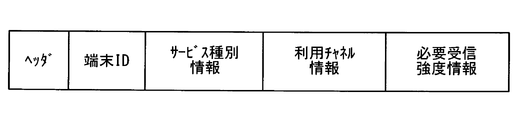
- FIG. 3 is a diagram illustrating an example of the configuration of the WSA in the present embodiment.
- the WSA includes a header, a terminal ID, service type information, and usage channel information.
- the header is information for recognizing that the received data is WSA in the receiving communication terminal (that is, the vehicle-mounted device 1).
- the header may include information indicating the version of the WAVE standard, information for distinguishing WSA and other messages used in WAVE, and the like.
- the terminal ID is the terminal ID of the roadside device 2 that transmits the WSA. With this terminal ID, the vehicle-mounted device 1 that has received the WSA can identify the transmission terminal of the received WSA.
- the terminal ID is illustrated separately from the header, but may be included in the header or may be included in an external area of the WSA (such as a data link layer frame).
- the service type information is information indicating the type of service provided by the roadside device 2.
- the service type information is represented by a service ID (so-called PSID: Provider Service ID) set in advance for each service type.
- PSID Provider Service ID
- the vehicle-mounted device 1 that has received the WSA refers to the service type information included in the WSA, thereby determining the type of service corresponding to the WSA, that is, the type of service provided by the roadside device 2 that is the transmission source of the WSA. Can be identified.
- the usage channel information is information indicating the channel number of the service channel that the roadside unit 2 uses for providing the service among the first to fourth service channels.
- the vehicle-mounted device 1 can identify the service channel that the roadside device 2 uses for providing the service by referring to the use channel information.
- Use channel information corresponds to service channel information.
- the roadside communication control unit G1 generates data to be transmitted using the service channel and transmits the data to the roadside communication unit 21 during a period in which the roadside communication unit 21 performs communication using the service channel. Let Furthermore, the roadside communication unit 21 acquires data received during a period in which communication using the service channel is performed, and provides the data to the service processing unit G2.
- the service processing unit G2 provides a predetermined service (for example, a settlement service) to the vehicle-mounted device 1 in the wireless communication area based on information provided from the roadside communication control unit G1.
- a predetermined service for example, a settlement service
- the roadside device 2 providing a service to the vehicle-mounted device 1 means that the roadside device 2 is equipped with the vehicle-mounted device 1 via the vehicle-mounted device 1 or an occupant of the vehicle.
- the aspect which provides a service with respect to is also included.
- the vehicle-mounted device 1 When the vehicle-mounted device 1 receives a WSA transmitted from a roadside device 2 (details will be described later) satisfying a predetermined condition via a control channel, the vehicle-mounted device 1 and the roadside device 2 that is the transmission source of the WSA and a predetermined service channel Start communication using. And the service which the roadside machine 2 provides is enjoyed by transmitting / receiving various information with the roadside machine 2 using the service channel.
- starting communication with the roadside device 2 using a predetermined service channel is also expressed as opening a service channel.
- the vehicle-mounted device 1 When the predetermined service channel is not opened, the vehicle-mounted device 1 receives a control channel or uses another service channel at a certain time interval (for example, every 50 milliseconds). 1 and vehicle-to-vehicle communication.
- the vehicle-mounted device 1 includes a control unit 11, a narrow communication unit 12, a GNSS receiver 13, and an acceleration sensor 14.
- the control unit 11 is connected to each of the narrow area communication unit 12, the GNSS receiver 13, and the acceleration sensor 14 so as to be able to communicate with each other.
- the narrow area communication unit 12 includes an antenna that can transmit and receive radio waves in a frequency band used for communication with the roadside device 2 and other vehicle-mounted devices 1, and other antennas that exist in the wireless communication area via the antenna. Wireless communication with the other communication terminal (for example, the roadside device 2). More specifically, the narrow area communication unit 12 demodulates a signal received by the antenna and outputs the demodulated signal to the control unit 11, modulates data input from the control unit 11, further converts the data into a radio wave, and transmits the radio wave.
- the signal received by the narrow area communication unit 12 corresponds to various messages transmitted from the roadside device 2, such as WSA.
- the narrow area communication unit 12 has two operation modes: a mode for performing communication using a control channel and a mode for performing communication using a service channel. That is, both communication using the control channel and communication using the service channel are performed via the narrow area communication unit 12.
- the narrow area communication unit 12 corresponds to a wireless communication unit.
- switching from communication using the control channel to communication using the service channel, and switching from communication using the service channel to communication using the control channel may be performed based on an instruction from the control unit 11.
- which service channel to use among the first service channel to the fourth service channel may be determined based on an instruction from the control unit 11.
- the narrow area communication unit 12 outputs the radio wave intensity of the received signal (hereinafter referred to as reception intensity) to the control unit 11 in association with the received data.
- reception intensity may be measured using, for example, a known RSSI circuit.
- the GNSS receiver 13 acquires data indicating the current position of the GNSS receiver 13 by receiving radio waves from a satellite used in GNSS (Global Navigation Satellite System).
- the current position information acquired by the GNSS receiver 13 may be represented by, for example, latitude, longitude, and altitude.
- the altitude information is a height from a predetermined reference surface (for example, the sea surface).
- the position information acquired by the GNSS receiver 13 is sequentially provided to the control unit 11 (for example, every 100 milliseconds).
- the acceleration sensor 14 detects acceleration acting in the front-rear direction of the host vehicle. It is assumed that the vehicle-mounted device 1 is attached to the host vehicle in a predetermined posture so that the acceleration detection direction by the acceleration sensor 14 coincides with the front-rear direction of the host vehicle.
- the own vehicle here refers to a vehicle on which the vehicle-mounted device 1 is mounted.
- the acceleration sensor 14 is preferably a three-axis acceleration sensor that detects acceleration acting in three axial directions orthogonal to each other in the front-rear direction, the left-right direction, and the vertical direction of the host vehicle.
- the control unit 11 is configured as a normal computer, and includes a well-known CPU, a non-volatile memory such as a ROM and a flash memory, a volatile memory such as a RAM, an I / O, and a bus line connecting these configurations (whichever Are also not shown).
- the memory 11M included in the control unit 11 includes a non-volatile storage area and a rewritable storage area, and is realized by, for example, a flash memory, a ROM, a RAM, or the like included in the control unit 11.
- the nonvolatile storage area of the memory 11M stores program modules and data (for example, various thresholds described later) for executing various processes, a terminal ID assigned to the vehicle-mounted device 1, and the like.
- data indicating a list of services that can be used by the vehicle-mounted device 1 is also stored in a nonvolatile, more preferably a rewritable storage area of the memory 11M.
- the service list may be a list of service IDs corresponding to services that can be used by the vehicle-mounted device 1.
- the service that can be used by the vehicle-mounted device 1 includes a service that can be used by the vehicle or a passenger of the vehicle via the vehicle-mounted device 1.
- This memory 11M corresponds to a service storage unit.
- a peripheral roadside machine list which will be described later, is stored in the rewritable storage area of the memory 11M.
- the control unit 11 includes a narrow area communication control unit F1, a reception intensity acquisition unit F2, a mobile system information acquisition unit F3, and roadside device management as functional blocks realized by executing the above program modules.
- a unit F4 a change degree calculation unit F6, a transmission terminal determination unit F5, and a service type determination unit F7. Note that some or all of the functions executed by the control unit 11 may be configured in hardware by one or a plurality of ICs.
- the narrow area communication control unit F1 controls the operation of the narrow area communication unit 12, and switches between communication using the control channel and communication using the service channel.
- the narrow area communication control unit F ⁇ b> 1 generates data to be transmitted from the narrow area communication unit 12 according to the operation mode of the narrow area communication unit 12, and causes the narrow area communication unit 12 to transmit the data. Furthermore, the data received by the narrow area communication unit 12 is acquired and provided to other functional blocks (for example, the service type determination unit F7), or processing corresponding to the received data is performed.
- the narrow area communication control unit F1 acquires the WSA or the like that the roadside device 2 transmits using the control channel during the period when the narrow area communication unit 12 performs communication using the control channel.
- the reception intensity acquisition unit F2 included in the narrow area communication control unit F1 is a functional block that acquires the reception intensity when the narrow area communication unit 12 receives a signal (for example, WSA) transmitted from the roadside device 2.
- WSA a signal
- the narrow area communication control unit F1 associates the WSA with the reception intensity when the WSA is received, and provides it to the roadside device management unit F4.
- the narrow-area communication control unit F1 is the roadside device 2 whose service is provided to the own terminal. If it is determined, communication with the roadside device 2 using a predetermined service channel is started.
- the predetermined service channel here is a service channel specified by the WSA usage channel information transmitted from the roadside device 2 among the first to fourth service channels.
- This narrow area communication control unit F1 corresponds to a wireless communication control unit.
- the mobile system information acquisition unit F3 sequentially detects the current position of the terminal itself (for example, every 100 milliseconds) based on the signal input from the GNSS receiver 13. Further, as a more preferable aspect, the mobile system information acquisition unit F3 sequentially acquires the movement speed of its own terminal (for example, every 100 milliseconds). For example, the movement system information acquisition unit F3 may calculate the movement speed of the own terminal by integrating the output value of the acceleration sensor 14. Alternatively, the moving speed may be calculated from the amount of change per unit time of the current position.
- the position information acquired by the GNSS receiver 13 may be corrected by using a known method based on detection values of the acceleration sensor 14 and a gyro sensor (not shown).
- the current position of the terminal itself may be estimated autonomously using a known self-position estimation method based on the detected values of the acceleration sensor 14 and the gyro sensor.
- the mobile system information acquisition unit F3 does not perform the process for specifying the current position, but the position detector including the GNSS receiver 13 performs the arithmetic process for specifying the current position.
- the information acquisition unit F3 may be configured to acquire the calculation result.
- the current location and the moving speed of the terminal acquired by the mobile system information acquisition unit F3 are provided to the roadside device management unit F4.
- information indicating the position of the terminal itself and information indicating the movement speed are collectively referred to as movement system information.
- the mobile system information is used to determine whether or not the terminal is moving, to specify the moving distance of the terminal.
- the roadside machine management unit F4 manages information about the roadside machine 2 existing around the terminal based on the WSA input from the narrow area communication control unit F1 and the reception strength thereof.
- the vicinity of the own terminal is a range where the transmission source of the currently received signal exists, and is a range including at least the wireless communication area of the own terminal.
- the roadside machine management unit F4 identifies the roadside machine 2 existing around the own terminal based on the terminal ID included in the WSA acquired from the narrow area communication control unit F1, and exists around the own terminal. For each roadside machine 2, information about the roadside machine 2 (referred to as roadside machine information) is held. For example, the roadside machine management unit F4 holds roadside machine information for each roadside machine 2 present in the vicinity of the own terminal, based on a peripheral roadside machine list (see FIG. 5) that is a list of the roadside machines 2 existing around the own terminal. .
- the peripheral roadside machine list shown in FIG. 5 represents a peripheral roadside machine list when there are three roadside machines 2 with terminal IDs 1, 3, and 4 around the terminal.
- the roadside machine information here is service type information indicating the type of service provided by the roadside machine 2, use channel information indicating a service channel used for providing the service, and It includes data indicating the WSA reception history transmitted from the roadside device 2 (hereinafter, reception history data).
- the service type information is the same information as the service type information included in the WSA, and stores, for example, a service ID included in the received WSA.
- the used channel information is the same information as the used channel information included in the WSA, and is represented by, for example, a channel number.
- the reception history data is data in which the reception time and the reception intensity are associated with each other when the WSA is received from the roadside device 2 corresponding to the roadside device information to which the reception history data belongs.
- the position of the terminal and the speed at that time are stored in association with each other.
- the position information and the speed information are used to specify the movement status of the own terminal such as whether or not the own terminal is moving and the moving distance.
- the reception history data may be updated sequentially (for example, addition of data) every time WSA is received from the roadside device 2.
- the roadside machine management unit F4 updates the roadside machine information (mainly reception history data) about the roadside machine 2 that is the transmission source of the WSA.
- the roadside unit information of the roadside unit 2 corresponding to the transmission source of the received signal may be updated every time a signal including information that can specify the transmission source is received.
- the information other than WSA that can specify the transmission source corresponds to, for example, a message of a type other than WSA.
- the service type information and the use channel information included in the roadside device information do not need to be updated every time WSA is received, and once registered, the data may be retained.
- the transmission terminal determination unit F5 determines whether a certain roadside device 2 existing around the terminal itself It is determined whether or not the terminal is a roadside device 2 whose service is to be provided.
- the roadside device 2 whose service is provided by its own terminal is a roadside that provides a service to a vehicle that travels in a lane (that is, its own lane) on which the vehicle (that is, its own vehicle) is mounted.
- Machine 2 the roadside machine 2 that does not target its own terminal is, for example, a roadside machine 2 for providing a service to a vehicle traveling in a lane in which the host vehicle is not traveling, such as an oncoming lane. Applicable.
- the roadside machine 2 that does not provide the service of its own terminal travels on a vehicle that runs on a road that intersects with its own lane in the vicinity of the intersection, or on a road that is adjacent to the road on which the host vehicle runs in the height direction.
- the roadside machine 2 that provides a service to the vehicle is also applicable.
- the two roads provided in the height direction correspond to, for example, an expressway and a general road provided along the expressway.
- the roadside device 2 for which the own terminal is the target of service provision will be referred to as the own terminal target roadside device 2 hereinafter. Further, the roadside device 2 that does not target its own terminal for service provision is referred to as its own terminal non-target roadside device 2.
- This transmission terminal determination unit F5 determines whether or not the roadside device 2 is the target terminal-side roadside device 2 based on the tendency of the change in WSA reception intensity received from the roadside device 2 and the magnitude thereof. To do.
- the transmitting terminal determination unit F5 determines that the roadside device 2 itself is based on the tendency and magnitude of the change in WSA reception intensity received from the roadside device 2. The reason why it can be determined whether or not the terminal target roadside device 2 will be described.
- FIG. 7 shows a roadside machine 2A whose service is provided for a vehicle traveling in the lane LA along a road having lanes LA and LB whose traveling directions are opposite to each other, and a vehicle which is traveling in the lane LB. This represents a scene where the roadside machine 2B is provided.
- the roadside machine 2A is provided on the lane LA side of the road.
- the roadside machine 2A is a roadside machine 2 that provides a traffic information transmission service to vehicles traveling on the lane LA.
- the roadside machine 2B is provided on the lane LB side of the road.
- the roadside machine 2B is a roadside machine 2 that provides a traffic information transmission service to a vehicle traveling on the lane LB.
- the white arrows on the lanes LA and LB in the figure indicate the traveling direction of the vehicle in the lane, and the traveling direction of the vehicle traveling in the lane LA is the left side as viewed in the figure, and travels in the lane LB.
- the traveling direction of the vehicle is the right side as viewed in the figure.
- Each of the short broken line 33A, the long broken line 32A, and the solid line 31A in the figure represents a boundary line in a range where a signal transmitted by the roadside device 2A reaches a predetermined level or more.
- the short broken line 33A is, for example, the roadside device 2A.
- the long broken line 32A represents the boundary line of the range (intermediate level area) where the WSA transmitted by the roadside device 2A reaches at a level (for example, ⁇ 80 dBm) stronger than the decoding limit level by a certain value or more.
- a solid line 31A represents a boundary line in a range (a strong level area) where the WSA transmitted by the roadside device 2A reaches at a stronger level (for example, ⁇ 70 dBm).
- each of the short broken line 33B, the long broken line 32B, and the solid line 31B in the figure represents a boundary line in which a signal transmitted by the roadside device 2B reaches above a predetermined level. This corresponds to the broken line 32A and the solid line 31A.
- the wireless communication area of the roadside device 2B is formed so as to extend to the lane LA where vehicles that are not intended for service provision by the roadside device 2B travel.
- the vehicle traveling in the lane LB not only the vehicle traveling in the lane LB but also the vehicle traveling in the lane LA receives the WSA transmitted by the roadside machine 2A.
- the wireless communication area of the roadside machine 2 includes a region (lane LB) through which a vehicle to be provided with service passes and a region (lane LA) through which a vehicle not to be provided with service passes. It is preferably formed so as not to include.
- lane LA a region through which a vehicle not to be provided with service passes.
- the vehicle 6 is a vehicle equipped with the vehicle-mounted device 1 and travels on the lane LA in the direction in which the roadside machine 2A exists from the point P0 before entering the wireless communication area of the roadside machine 2B.
- the vehicle-mounted device 1 is the vehicle-mounted device 1 that is registered as a service that can be used in its own terminal, both of the traffic information transmission service by the roadside device 2A and the traffic information transmission service by the roadside device 2B.
- An arrow indicated by reference numeral 61 in the drawing represents a movement route of the vehicle 6 (strictly, the vehicle-mounted device 1).
- the vehicle 6 starts to receive the WSA transmitted by the roadside device 2B, and then sequentially receives the WSA transmitted by the roadside device 2B until it passes the point P2.
- the point P1 is a point where the vehicle-mounted device 1 enters the wireless communication area of the roadside device 2B
- the point P2 is a point where the vehicle-mounted device 1 leaves the wireless communication area of the roadside device 2B.
- FIG. 8 is a conceptual diagram showing a change in WSA received intensity transmitted from the roadside device 2B received by the vehicle-mounted device 1 as the vehicle-mounted device 1 moves from the point P1 to the point P2.
- the horizontal axis in FIG. 8 indicates the moving distance of the vehicle-mounted device 1, and the vertical axis indicates the WSA reception intensity received by the vehicle-mounted device 1.
- the change in the reception intensity of the WSA transmitted from the roadside device 2B receives the WSA transmitted from the roadside device 2A described later. Compared to the case (see FIG. 9), it is relatively gentle, and its maximum value is also a relatively small value.
- the roadside unit 2B is a roadside unit 2 that provides services to vehicles traveling in the lane LB, so that the center (region where the signal strength is strong) of the wireless communication area is on the lane LB.
- the signal transmitted by the roadside machine 2 attenuates as the distance from the roadside machine 2B increases, as indicated by a solid line 31B, a long broken line 32B, and a short broken line 33B in FIG.
- a WSA with a strong signal strength is basically difficult to reach the lane LA on which a vehicle that is not originally provided for service travels.
- the vehicle 6 crosses a region between the short broken line 33 ⁇ / b> B and the long broken line 32 ⁇ / b> B where the signal strength is relatively low.
- the change accompanying the movement of the reception intensity becomes relatively gradual. That is, when the vehicle-mounted device 1 receives the WSA from the non-target roadside device 2 of its own terminal, the change accompanying the movement of the reception intensity becomes gradual.
- the maximum value is also a relatively small value.
- a point P3 is a point where the vehicle-mounted device 1 enters the wireless communication area of the roadside device 2A
- a point P8 is a point where the vehicle-mounted device 1 leaves the wireless communication area of the roadside device 2A.
- the center part of the wireless communication area (the area where the signal strength is strong) is designed to be on the lane LA. .
- the WSA reception intensity from the roadside device 2A increases as it is closer to the roadside device 2A. That is, as the host vehicle travels from the point P3, the reception intensity of the signal transmitted from the roadside device 2A in the vehicle-mounted device 1 increases. Then, when the host vehicle further travels, the host vehicle will move away from the roadside machine 2A, so that the reception intensity of the WSA transmitted from the roadside machine 2A decreases.
- the vehicle-mounted device 1 travels so as to pass near the center of the wireless communication area of the roadside device 2A. This is because the vehicle-mounted device 1 moves across a plurality of boundary lines (for example, a long broken line 32A, a solid line 31A, etc.) conceptually indicating an area where a signal transmitted from the roadside machine 2A in FIG. Means to do.
- a plurality of boundary lines for example, a long broken line 32A, a solid line 31A, etc.
- FIG. 9 is a conceptual diagram showing a change in WSA received intensity transmitted from the roadside device 2A received by the vehicle-mounted device 1 as the vehicle-mounted device 1 moves from the point P3 to the point P8.
- the horizontal axis in FIG. 9 indicates the moving distance of the vehicle-mounted device 1, and the vertical axis indicates the WSA reception intensity transmitted from the roadside device 2.
- a point P4 shown in FIG. 9 indicates a point where the vehicle-mounted device 1 enters the region surrounded by the long broken line 32A (that is, the middle level area), and the point P5 is a region where the vehicle-mounted device 1 is surrounded by the solid line 31A. (Ie, a point entering the strong level area).
- a point P6 is a point where the vehicle-mounted device 1 leaves the strong level area of the roadside device 2A, and a point P7 represents a point where the vehicle-mounted device 1 leaves the middle level area of the roadside device 2A.
- the vehicle-mounted device 1 Since the vehicle-mounted device 1 travels so as to pass near the center of the wireless communication area of the roadside device 2A, as shown in FIG. 9, the vehicle-mounted device 1 approaches and separates from the roadside device 2A.
- the degree of change in the reception intensity in the process is greater than the degree of change associated with the movement of the vehicle-mounted device 1 of the WSA reception intensity transmitted from the roadside device 2B. More specifically, the degree of increase in reception strength when the vehicle-mounted device 1 approaches the roadside device 2A is an increase in reception strength accompanying the movement of the vehicle-mounted device 1 when the vehicle-mounted device 1 approaches the roadside device 2B. Greater than degree.
- the degree of decrease in reception strength when the vehicle-mounted device 1 leaves the roadside device 2A is greater than the degree of decrease in reception strength when the vehicle-mounted device 1 leaves the roadside device 2B.
- the degree of increase and the degree of decrease here correspond to the magnitude of the slopes of the graphs shown in FIGS. 8 and 9, and the degree of increase is, for example, the amount of increase per unit meter. The amount of reduction per unit meter may be used.
- the reception intensity is saturated and the amount of change becomes gradual.
- the reception intensity at that time is a value large enough to be distinguished from the case where it is closest to the roadside device 2B.
- the vehicle-mounted device 1 receives the WSA from the own terminal target roadside device 2 (for example, the roadside device 2A) and the WSA from the own terminal non-target roadside device 2 (roadside device 2B). Is different from the reception strength change and the reception strength itself.
- the transmission terminal determination unit F5 uses the change in reception strength as described above and the difference in the maximum value of reception strength, so that the roadside device 2 that is transmitting the currently received WSA Then, it is determined whether or not it is the own terminal target roadside device 2.
- the transmission terminal determination unit F5 can determine whether or not it is the own terminal target roadside device 2.
- the increase degree of reception intensity is more than the threshold for approach, it does not simply indicate that the roadside device 2 is the own terminal target roadside device 2, but the vehicle-mounted device 1 It means that the roadside machine 2 is approaching.
- the approach threshold used here may be appropriately designed by various tests and simulations.
- the approach threshold value may be an increase amount of the reception intensity per certain moving distance.
- the fixed moving distance may be 1 meter, or 5 meters or 10 meters.
- the degree of increase in reception strength for comparison with the approach threshold may be calculated in correspondence with the approach threshold.
- the threshold for approach is the amount of increase in reception strength per meter
- the degree of increase may also be the amount of increase in reception strength per meter.
- a mode in which it is determined whether or not the roadside machine 2 that is the transmission source of the received signal is the own terminal target roadside machine 2 based on the degree of increase in reception strength accompanying movement is not limited to this.
- the roadside device 2 that is the transmission source of the received signal is its own terminal target roadside device 2. You may judge. This is because the vehicle-mounted device 1 is mounted on a vehicle, so that the position of the vehicle-mounted device 1 can be expected to move with time.
- the WSA reception strength from the non-target roadside device 2 such as the roadside device 2B for the opposite lane is relatively low, while the WSA reception strength from the target terminal target roadside device 2 is It is expected to reach a fairly strong reception strength.
- the vehicle-mounted device 1 determines that the in-vehicle device target roadside device 2 It can be considered that the WSA is received.
- the roadside device 2 that is transmitting a WSA having a reception strength equal to or higher than a predetermined threshold (strength threshold Pth) is the target terminal-side roadside device 2.
- the strength threshold value Pth may be appropriately designed to a sufficiently large value so as not to be received from the local terminal non-target roadside device 2.
- the change degree calculation unit F6 included in the transmission terminal determination unit F5 calculates the degree of increase in reception intensity based on received radio waves and mobile system information at a plurality of points in time, which are stored as reception history data for each roadside device 2. .
- the past position information is referred to in order of newest time, and the reception intensity at a point a certain distance before is acquired from the current position information (or the latest position information).
- an increase amount (that is, an increase degree) per fixed distance is calculated from the difference between the current reception strength (or the latest reception strength) and the read reception strength.
- the fixed distance may be a distance corresponding to the above-described approach threshold.
- the WSA when there is no data that is exactly a certain distance from the past data, it may be obtained by interpolating with previous and subsequent data. Also, when the WSA is received a plurality of times at the same (including substantially the same) point, such as when the terminal is stopped, among them, the value with the highest reception strength is calculated for the increase degree. It should be used. This is because it is conceivable that the reception intensity changes due to the presence of another moving body even during the stop.
- the service type determination unit F7 determines, based on the service list stored in the memory 11M, whether or not the service provided by the roadside device 2 existing in the vicinity of the own terminal is a service that can be used in the own terminal. .
- the roadside machine 2 existing around the terminal corresponds to the roadside machine 2 registered in the peripheral roadside machine list. Further, the service provided by the roadside device 2 may be specified by the service type information included in the roadside device information of the roadside device 2.
- the service type determination unit F7 determines that the service corresponding to the WSA is a service that can be used in the own terminal. judge. If the service ID of the service provided by the roadside device 2 is not registered in the service list, it is determined that the service corresponding to the WSA is not a service that can be used in the own terminal.
- reception related processing Next, the reception related process which the control part 11 implements is demonstrated using the flowchart shown in FIG.
- This reception-related processing starts communication using the service channel for enjoying the service provided by the roadside device 2 and the roadside device 2, triggered by reception of the WSA transmitted from the roadside device 2.
- This is a process for determining whether or not. Therefore, the flowchart shown in FIG. 10 may be started when the narrow area communication control unit F1 receives WSA.
- step S1 the roadside device management unit F4 acquires the received WSA data and the received strength of the WSA from the narrow area communication control unit F1, and updates the surrounding roadside device list. That is, the roadside device 2 (hereinafter referred to as a transmission terminal) that is the transmission source of the WSA is specified from the terminal ID included in the WSA. And the roadside machine information corresponding to the transmitting terminal is updated.
- the roadside device management unit F4 acquires the received WSA data and the received strength of the WSA from the narrow area communication control unit F1, and updates the surrounding roadside device list. That is, the roadside device 2 (hereinafter referred to as a transmission terminal) that is the transmission source of the WSA is specified from the terminal ID included in the WSA. And the roadside machine information corresponding to the transmitting terminal is updated.
- the transmitting terminal is added to the peripheral roadside apparatus list, and roadside apparatus information based on the WSA is generated and stored.
- step S1 When the process in step S1 is completed, the process proceeds to step S2.
- step S2 the transmission terminal determination unit F5 performs a transmission terminal determination process and proceeds to step S3.
- the transmission terminal determination process is a process of determining whether or not the transmission terminal is the own terminal target roadside device 2.
- the change degree calculation unit F6 calculates the increase degree of the reception intensity. And the transmission terminal determination part F5 determines whether the increase degree calculated by the change degree calculation part F6 is more than the threshold value for approach.
- the increase degree is equal to or greater than the approaching threshold value, this transmitting terminal determines that it is the own terminal target roadside device 2.
- the transmitting terminal does not determine that the terminal is the target terminal-side roadside device 2.
- the transmission terminal determination unit F5 determines whether or not the reception strength of the WSA acquired this time (that is, the latest) is equal to or higher than the strength threshold value Pth. If the WSA received strength acquired this time is equal to or greater than the strength threshold Pth, the transmitting terminal determines that it is the target terminal-side roadside device 2. On the other hand, if the WSA reception strength acquired this time is not equal to or greater than the strength threshold value Pth, the transmitting terminal does not determine that it is the target terminal-side roadside device 2.
- step S3 becomes YES and the process proceeds to step S4.
- step S3 is NO and this flow is ended.
- step S2 if the reception history data corresponding to the transmission terminal is not enough data to calculate the degree of increase, that is, if the number of receptions is still insufficient, reception is performed. Only a comparison between the intensity and the intensity threshold value Pth may be performed. Alternatively, if the number of receptions is still insufficient, the transmitting terminal does not determine that it is the target terminal-side roadside device 2 and terminates this flow as in the case where step S3 is NO. Also good.
- step S4 the service type determination unit F7 determines whether or not the service provided by the transmission terminal is a service that can be used in the own terminal. If the service provided by the transmitting terminal is not a service that can be used by the terminal itself, step S4 is NO and this flow ends. That is, the service channel indicated by WSA is not opened.
- step S4 becomes YES and the process proceeds to step S5.
- step S5 the narrow area communication control unit F1 starts communication using the service channel with the roadside device 2 using the service channel indicated in the use channel information of the roadside device information corresponding to the transmitting terminal.
- step S4 which determines a service type after a transmission terminal determination process (step S2) was illustrated above, it is not restricted to this. It is good also as an aspect which implements the reception relevant process mentioned above only to the transmission terminal which provides the service which an own terminal can use. In other words, when the WSA is received and the service type information indicated in the WSA is a service that can be used in the own terminal, the above-described reception-related processing may be performed. According to such an aspect, it is possible to omit the trouble of managing roadside machine information for the roadside machine 2 that provides a service that cannot be used by the terminal itself, or performing a transmission terminal determination process.
- step S2 when the transmitting terminal determination unit F5 receives WSA from a certain roadside device 2, the degree of increase in the reception intensity of the WSA received from the roadside device 2 is equal to or greater than a predetermined approach threshold. And whether or not the received intensity of the received WSA is equal to or greater than a predetermined intensity threshold Pth (step S2).
- step S3 when the degree of increase in the reception strength of the WSA received from the roadside device 2 is equal to or greater than the approach threshold, or the received strength of the WSA is equal to or greater than the strength threshold Pth.
- step S4 communication using the service channel with the roadside device 2 is started (step S4).
- the approach threshold value and the strength threshold value Pth used in the transmission terminal determination process in step S2 are received when the WSA is received from the own terminal target roadside device 2, as described with reference to FIGS. And a threshold value set by paying attention to the tendency of the change in the received intensity and the difference in the magnitude of the received intensity that occurs when the WSA is received from the non-target roadside device 2.
- the own terminal target roadside device 2 it is possible to determine whether or not the received WSA transmission terminal is the own terminal target roadside device 2, and as a result, the own terminal non-target roadside device 2 and the predetermined service Starting communication using a channel can be suppressed.
- the transmission terminal determination unit F5 performs not only a comparison between the degree of increase in reception strength and the approach threshold value, but also a comparison between the magnitude of reception strength and the threshold value Pth for the received WSA. It is determined whether or not the transmitting terminal is its own terminal target roadside device 2.
- the state of being sufficiently close to the roadside device 2 means a state where the vehicle-mounted device 1 exists in the strong level area shown in FIG.
- the terminal receives the WSA from the roadside machine 2A when the positional relationship between the large vehicle and the own vehicle with respect to the roadside machine 2 changes.
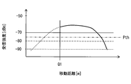
- a point Q1 in FIG. 11 represents a point at which the WSA from the roadside device 2 has started to be received, and a thick line portion of the graph represents a change in the strength of the WSA received.
- a broken line portion in the graph represents an assumed value of WSA reception intensity that could not be actually received due to the presence of a large vehicle or the like.
- the WSA reception intensity from the roadside device 2 is in a saturated state (a sufficiently increased state), and therefore the degree of increase may not exceed the approach threshold.
- the transmitting terminal that should be determined to be the own terminal target roadside device 2 is not determined to be the own terminal target roadside device 2 only by comparing the increase degree with the approach threshold.
- the transmitting terminal It is determined to be 2.
- the two-dot chain line in the figure represents the intensity threshold value Pth.
- the change degree calculation unit F6 calculates the increase degree, it is necessary to receive the WSA from the same transmission terminal a plurality of times.
- the above determination can be performed based on the reception intensity of one WSA (that is, a newly received WSA).
- the own terminal is sufficiently close to the roadside device 2A, it may be assumed that the terminal is going away from the transmitting terminal soon, so the service provided by the transmitting terminal is used by the own terminal. If the service is possible, it is preferable to start communication using the service channel with the transmitting terminal as quickly as possible.
- the terminal even if the terminal receives the WSA for the first time after the terminal has sufficiently approached the roadside device 2A, it can be promptly determined according to the result of the comparison between the received intensity and the strength threshold. Communication using the service channel with the transmitting terminal can be started.
- the received WSA transmitting terminal uses the comparison of the degree of increase of the received strength and the threshold for approach and the comparison of the magnitude of the received strength and the threshold for strength Pth together. Although the aspect which determines whether it is is illustrated, it is not restricted to this.
- the transmission terminal determination process may be performed by comparing the magnitude of the reception strength and the threshold value Pth for strength without performing the comparison between the degree of increase in reception strength and the threshold value for approach.
- the intensity threshold value Pth is used in the transmission terminal determination process, the following problem may occur.
- the strength threshold value Pth When the strength threshold value Pth is relatively low, the possibility that the own terminal non-target roadside device 2 such as the oncoming lane roadside device 2 is erroneously determined to be the own terminal target roadside device 2 increases. On the other hand, if the strength threshold Pth is set to a relatively high value, the possibility that the own terminal non-target roadside device 2 is erroneously determined to be the own terminal target roadside device 2 can be suppressed. Unless it is sufficiently close to the roadside device 2, communication using the service channel with the transmitting terminal cannot be started, and the timing for enjoying the service is delayed. That is, the determination of the strength threshold value Pth involves a difficulty of considering the balance between suppression of erroneous determination and delay in communication start timing.
- the transmitting terminal is in the stage before the terminal sufficiently approaches the roadside machine 2A, that is, the stage where the terminal is approaching the roadside machine 2. It can be determined whether or not the terminal-side target roadside device 2. That is, by using the comparison between the degree of increase and the approach threshold value, communication using the service channel with the roadside device 2 can be started before the vehicle-mounted device 1 sufficiently approaches the roadside device 2. Thereby, it can suppress that the timing which enjoys a service is overdue.
- the determination criterion of the transmission terminal determination process in the process in which the vehicle-mounted device 1 approaches the roadside device 2 and the own terminal sufficiently approach the roadside device 2. In this state, it is possible to substantially use the determination criterion of the transmission terminal determination process in the state where the transmission terminal is determined. That is, in the process in which the vehicle-mounted device 1 approaches the roadside device 2, it is determined by comparing the degree of increase with the threshold for approach, and when the terminal is sufficiently close to the roadside device 2, the reception strength And the intensity threshold value Pth.
- the approach threshold value and the strength threshold value corresponding to the positional relationship between the vehicle-mounted device 1 and the roadside device 2 are obtained. It can be set, and it is possible to more appropriately determine whether or not the transmitting terminal is the own terminal target roadside device 2 in each of the approaching state and the sufficiently approaching state.
- the in-vehicle device 1 includes the strength threshold value Pth
- the present invention is not limited thereto.
- the on-vehicle device 1 may not include the strength threshold value Pth, and the roadside device 2 may transmit WSA (see FIG. 12) including the necessary reception strength information that specifies the strength threshold value described above.
- WSA see FIG. 12
- the roadside device 2 uses the strength threshold according to the necessary reception strength information, and the roadside device 2 is the target terminal-side roadside device 2. It is determined whether or not.
- the necessary reception strength information A determination as to whether or not the roadside device 2 is the target terminal-side roadside device 2 may be carried out by giving priority to the strength threshold value determined accordingly.
- the vehicle-mounted device 1 can determine whether or not the roadside device 2 is the target terminal-side roadside device 2 by using a threshold for strength according to the installation environment of the roadside device 2. It becomes like this.
- ⁇ Modification 2> in a situation where communication is performed using the service channel with the roadside device 2 that transmits the WSA including the necessary reception strength information, the reception strength of the signal received from the roadside device 2 is When the reception strength indicated by the required reception strength information acquired from the roadside device 2 is less than the reception strength, communication using the service channel with the roadside device 2 may be terminated in accordance with a predetermined procedure.
- the degree of increase in received strength is calculated as the amount of increase in received strength accompanying the movement of the terminal, and the approach threshold is also a value based on the moving distance and the amount of change in received strength.
- the degree of increase in reception strength is the amount of increase in reception strength over time (that is, the amount of increase in reception strength per fixed time), and the approach threshold also focuses on the amount of change in reception strength per fixed time. It is good also as a value designed as above.
- a plurality of types of approach thresholds corresponding to the moving speed are prepared in advance so that the approaching threshold value becomes larger as the moving speed increases, or a predetermined speed is assumed. It is preferable that the approach threshold value designed as described above is dynamically corrected according to the moving speed.
- the transmitting terminal is the own terminal target roadside device 2 based on a comparison between the degree of increase in reception strength and the approach threshold. It is good also as an aspect which does not determine whether it is. This is because if the on-vehicle device 1 moves little, the change in the received intensity decreases, and the determination accuracy may decrease.
- the threshold here is a value designed as appropriate, and may be, for example, a speed (about 10 km / h) when the host vehicle is slowing down.
- the transmission terminal determination unit F5 has already performed communication using the service channel, and the roadside device 2 whose communication has been normally terminated in accordance with a predetermined procedure may be excluded from the target of the transmission terminal determination process. Good.
- the fact that the communication using the service channel has already been performed means that the service provided by the roadside device 2 has already been enjoyed, and the necessity of performing communication using the service channel again with the roadside device 2 is low. This is because it is assumed.
- Whether or not a certain roadside device 2 has already performed communication using a service channel is determined by preparing a flag indicating whether or not communication has already been performed in the roadside device information. What is necessary is just to determine with the flag. For example, when communication using a service channel with a certain roadside device 2 is completed by a normal procedure, the flag may be changed to a state indicating that communication has been performed. Here, whether or not communication has already been performed is reset (set to an unexecuted state) when it is deleted from the peripheral roadside device list.
- the control unit 11 determines whether or not the own terminal is approaching the transmission terminal or is separated based on the reception history data corresponding to the transmission terminal.
- a distance change determination unit F8 (see FIG. 13) may be provided.
- the distance change determination unit F8 refers to the reception history data corresponding to the transmission terminal, and may determine that it is approaching when the reception intensity tends to increase. Moreover, what is necessary is just to determine with having separated when reception intensity is decreasing. This distance change determination unit F8 corresponds to a departure determination unit.
- the narrow area communication control unit F1 is determined to be the roadside unit 2 that has already performed communication using the service channel and is separated by the distance change determination unit F8. You may exclude the roadside machine 2 from the object of a transmission terminal determination process.
- the narrow area communication control unit F1 the narrow area communication control unit F1
- the transmission terminal determination process for the machine 2 may be performed with priority over other roadside machines 2.
- the change degree calculation unit F6 calculates the increase degree of the reception intensity, but the present invention is not limited to this.
- the degree-of-change calculating unit F6 may calculate the degree of decrease in received strength based on the same method as the method for calculating the degree of increase.
- the degree of decrease is an index indicating that the received intensity decreases more rapidly as the value increases.
- the roadside device 2 in which the degree of decrease in received strength is equal to or greater than a predetermined threshold means that the roadside device 2 is the target terminal target roadside 2.
- a predetermined threshold departure threshold
- the transmission terminal determination unit F5 can determine whether or not the received WSA transmission terminal is its own terminal target roadside device 2. In other words, the transmission terminal determination unit F5 determines that the roadside device 2 whose degree of decrease in reception intensity is equal to or greater than the departure threshold is the roadside device 2 whose service is provided by the own terminal.
- the terminal can start receiving the WSA for the first time when it begins to leave the roadside machine 2, for example.
- the roadside machine 2 can be determined to be the own terminal target roadside machine 2. As a result, communication using the roadside device 2 and the service channel can be performed.
- the remaining time for communication with the transmitting terminal that has received WSA for the first time after starting to leave is shorter than that of other roadside devices 2 that are approaching. Therefore, for the roadside device 2 that is determined to be the target terminal-side roadside device 2 by comparing the departure threshold and the degree of decrease, the communication using the service channel is performed in preference to the other roadside devices 2. It is preferable to do.
- the vehicle-mounted device 1 may be used as a service providing terminal.
- the service providing terminal may be a communication terminal used in a mobile object.
- each communication terminal exemplifies a mode in which communication is performed based on the WAVE standard as an example.
- the present invention is not limited to this.
- Each communication terminal may perform communication based on another communication standard corresponding to WAVE.
- a channel used for substantial communication for providing (and enjoying) a service corresponds to a service channel.
- a channel used for transmitting information for starting communication using the channel corresponds to a control channel.
Landscapes
- Engineering & Computer Science (AREA)
- Computer Networks & Wireless Communication (AREA)
- Signal Processing (AREA)
- Mobile Radio Communication Systems (AREA)
- Traffic Control Systems (AREA)
- Telephone Function (AREA)
- Quality & Reliability (AREA)
- Physics & Mathematics (AREA)
- Electromagnetism (AREA)
Abstract
Description
路側機2は、路側機2が形成する無線通信エリア内に存在する車載器1と路車間通信を実施し、種々の情報を車載器1に送信したり、車載器1から種々の情報を取得したりすることで所定のサービスを実施する。この路側機2がサービス提供端末の一例に相当する。
次に、車載器1について説明する。車載器1は、コントロールチャネルを介して所定の条件を満たす路側機2(詳細は後述)から送信されたWSAを受信した場合には、そのWSAの送信元である路側機2と所定のサービスチャネルを用いた通信を開始する。そして、そのサービスチャネルを用いて路側機2と種々の情報を送受信することで、その路側機2が提供するサービスを享受する。以降では、路側機2と所定のサービスチャネルを用いた通信を開始することを、サービスチャネルをオープンするとも表現する。
次に、図10に示すフローチャートを用いて、制御部11が実施する受信関連処理について説明する。この受信関連処理は、路側機2から送信されたWSAを受信したことをトリガとして、その路側機2と、その路側機2が提供するサービスを享受するためのサービスチャネルを用いた通信を開始するか否かを判定する処理である。したがって、この図10に示すフローチャートは、狭域通信制御部F1がWSAを受信したときに開始されれば良い。
以上の構成によれば、送信端末判定部F5は、ある路側機2からのWSAを受信すると、路側機2から受信しているWSAの受信強度の増加度合いが所定の接近用閾値以上となっているか否か、及び、その受信したWSAの受信強度が所定の強度用閾値Pth以上となっているか否かを判定する(ステップS2)。そして、その結果、路側機2から受信しているWSAの受信強度の増加度合いが接近用閾値以上となっている場合、又は、その受信したWSAの受信強度が強度用閾値Pth以上となっている場合に(ステップS3 YES)、その路側機2とのサービスチャネルを用いた通信を開始する(ステップS4)。
以上では、強度用閾値Pthを車載器1が備える態様を例示したが、これに限らない。例えば、車載器1が強度用閾値Pthを備えずに、路側機2が、前述の強度用閾値を指定する必要受信強度情報を含むWSA(図12参照)を送信する態様としてもよい。そのような態様において車載器1は、必要受信強度情報を含むWSAを受信した場合には、その必要受信強度情報に応じた強度用閾値を用いて、その路側機2が自端末対象路側機2であるか否かの判定を実施する。
上述した変形例1において、必要受信強度情報を含むWSAを送信する路側機2と、サービスチャネルを用いた通信を実施している状況において、その路側機2から受信する信号の受信強度が、その路側機2から取得した必要受信強度情報に示される受信強度未満となった場合には、その路側機2とのサービスチャネルを用いた通信を、所定の手続きに則って終了させてもよい。
以上では、受信強度の増加度合いを、自端末の移動に伴う受信強度の増加量として算出するとともに、接近用閾値もまた、移動距離と受信強度の変化量に基づいた値としたが、これに限らない。例えば、受信強度の増加度合いは、時間の経過に伴う受信強度の増加量(つまり一定時間当たりの受信強度の増加量)とし、接近用閾値もまた、一定時間当たりの受信強度の変化量に着眼して設計される値としてもよい。
また、上述の変形例3においては、移動速度が所定の閾値以下となっている場合には、受信強度の増加度合いと接近用閾値との比較による、送信端末が自端末対象路側機2であるか否かの判定を行わない態様としてもよい。車載器1の移動が少ないと、受信強度の変化が少なくなってしまい、判定精度が低下する可能性があるためである。ここでの閾値は、適宜設計される値であって、例えば自車両が徐行している時の速度(10km/h程度)とすればよい。
送信端末判定部F5は、既にサービスチャネルを用いた通信を実施し、その通信が予め定められた手順に則って正常に終了した路側機2については、送信端末判定処理の対象から除外してもよい。既にサービスチャネルを用いた通信を実施したということは、既にその路側機2が提供するサービスを享受したことを意味し、再度その路側機2とサービスチャネルを用いた通信を実施する必要性は低いことが想定されるためである。
また、制御部11は、WSAを受信した場合に、その送信端末に対応する受信履歴データに基づいて、自端末が送信端末に接近していっているか否か、または離れていっているか否かを判定する距離変化判定部F8(図13参照)を備えていてもよい。例えば、距離変化判定部F8は、送信端末に対応する受信履歴データを参照し、受信強度が増加傾向にある場合には、接近していっていると判定すればよい。また、受信強度が減少傾向にある場合には離れていっていると判定すればよい。この距離変化判定部F8が離脱判定部に相当する。
また、上述した実施形態において、変化度合い算出部F6は、受信強度の増加度合いを算出するものとしたが、これに限らない。変化度合い算出部F6は、増加度合いの算出方法と同様の方法に基づいて、受信強度の減少度合いを算出してもよい。なお、ここでの減少度合いは、大きいほど急速に受信強度が減少していっていることを示す指標である。
以上では、路側機2がサービス提供端末として機能する態様を例示したが、これに限らない。例えば、車載器1をサービス提供端末として用いても良い。すなわち、サービス提供端末は、移動体で用いられる通信端末であってもよい。
Claims (10)
- 通信の接続制御のために用いられるコントロールチャネルと、前記コントロールチャネルとは異なるチャネルであって、サービスの提供のために割り当てられている複数種類のサービスチャネルのうちの何れかと1つと、を用いて、所定のサービスを提供するサービス提供端末(2)と無線通信を実施する無線通信部(12)と、前記無線通信部の動作を制御する無線通信制御部(F1)と、を備える車両用通信端末であって、
前記無線通信部は、前記コントロールチャネルを用いて前記サービス提供端末から送信される、前記サービス提供端末が提供する前記サービスの種別を示すサービス種別情報と、複数の前記サービスチャネルのうち、前記サービス提供端末が自端末との通信に利用する前記サービスチャネルを指定するサービスチャネル情報と、を含むサービス開始用情報を少なくとも受信するものであって、
前記車両用通信端末は、さらに、
前記サービス提供端末から送信され、前記無線通信部が受信した信号の受信強度を取得する受信強度取得部(F2)と、
前記無線通信部が前記サービス提供端末から前記サービス開始用情報に対応する信号を受信した場合に、その受信信号に対して前記受信強度取得部が取得した前記受信強度の大きさ、及び、その受信信号の送信元である前記サービス提供端末(以降、送信端末とする)から受信する信号の前記受信強度の変化の度合いの少なくとも何れか一方に基づいて、その送信端末が、自端末をサービス提供の対象とする前記サービス提供端末であるか否かを判定する送信端末判定部(F5)を備え、
前記無線通信制御部は、
前記送信端末判定部によって前記送信端末は自端末をサービス提供の対象とする前記サービス提供端末であると判定されるまでは、前記送信端末とは、その送信端末から送信された前記サービス開始用情報に含まれる前記サービスチャネル情報で指定されている前記サービスチャネルを用いた通信を開始しない、車両用通信端末。 - 請求項1において、
前記受信強度取得部によって取得された、前記送信端末から送信された信号の前記受信強度の増加度合いを算出する変化度合い算出部(F6)を備え、
前記送信端末判定部は、
前記変化度合い算出部によって算出された前記増加度合いが、自端末をサービス提供の対象とする前記サービス提供端末に対して自端末が接近しているか否かを判定するための接近用閾値以上となっている場合には、前記送信端末は、自端末をサービス提供の対象とする前記サービス提供端末であると判定する、車両用通信端末。 - 請求項1において、
前記受信強度取得部によって取得された、前記送信端末から送信された信号の前記受信強度の増加度合いを算出する変化度合い算出部(F6)を備え、
前記送信端末判定部は、
前記変化度合い算出部によって算出された前記増加度合いが、自端末をサービス提供の対象とする前記サービス提供端末に対して自端末が接近しているか否かを判定するための接近用閾値以上となっている場合、又は、前記受信強度取得部が取得した前記受信強度が、自端末をサービス提供の対象とする前記サービス提供端末から送信された信号を受信しているか否かを判定するための強度用閾値以上となっている場合には、前記送信端末は、自端末をサービス提供の対象とする前記サービス提供端末であると判定する、車両用通信端末。 - 請求項3において、
前記サービス開始用情報は、前記強度用閾値の値を指定する情報である必要受信強度情報を含み、
前記送信端末判定部は、前記必要受信強度情報を含む前記サービス開始用情報を受信した場合には、そのサービス開始用情報の送信元である前記サービス提供端末に対しては、前記受信強度取得部が取得した前記受信強度が、その送信元から受信したサービス開始用情報に含まれる前記必要受信強度情報によって定まる前記強度用閾値以上となっている場合に、そのサービス提供端末は自端末をサービス提供の対象とする前記サービス提供端末であると判定する、車両用通信端末。 - 請求項2から4の何れか1項において、
前記変化度合い算出部は、前記受信強度取得部によって取得された、前記送信端末から送信された信号の前記受信強度の減少度合いを算出し、
前記送信端末判定部は、
前記変化度合い算出部が算出した前記減少度合いが、自端末をサービス提供の対象とする前記サービス提供端末から自端末が離れていっているか否かを判定するための離脱用閾値以上となっている場合、前記送信端末は、自端末をサービス提供の対象とする前記サービス提供端末であると判定する、車両用通信端末。 - 請求項2から5の何れか1項において、
前記変化度合い算出部は、自端末の移動距離に対する前記受信強度の増加量を前記増加度合いとして算出する、車両用通信端末。 - 請求項2から5の何れか1項において、
前記変化度合い算出部は、一定時間当りの前記受信強度の増加量を前記増加度合いとして算出する、車両用通信端末。 - 請求項7において、
自端末の移動速度を特定するための移動系情報を取得する移動系情報取得部(F3)を備え、
前記送信端末判定部は、前記移動系情報取得部が取得した前記移動系情報から特定される自端末の移動速度が所定の閾値以下である場合には、前記増加度合いと前記接近用閾値との比較を行わない、車両用通信端末。 - 請求項1から8の何れか1項において、
前記送信端末判定部は、
前記送信端末を、自端末をサービス提供の対象とする前記サービス提供端末であると判定していない場合には、前記無線通信部が当該送信端末からの信号を受信する毎に、前記送信端末は自端末をサービス提供の対象とする前記サービス提供端末であるか否かの判定を逐次実施し、
前記送信端末は自端末をサービス提供の対象とする前記サービス提供端末であると判定するまでは、前記送信端末は自端末をサービス提供の対象とする前記サービス提供端末ではないとの判定を保持する、車両用通信端末。 - 請求項1から9の何れか1項において、
前記受信強度取得部によって取得された、前記送信端末から送信された信号の前記受信強度が減少傾向にある場合には、前記送信端末から自端末が離れていっていると判定する離脱判定部(F8)を備え、
前記送信端末判定部は、前記離脱判定部によって自端末が離れていっていると判定された前記送信端末については、自端末をサービス提供の対象とする前記サービス提供端末であるか否かの判定の対象から除外する、車両用通信端末。
Priority Applications (4)
| Application Number | Priority Date | Filing Date | Title |
|---|---|---|---|
| SG11201703518TA SG11201703518TA (en) | 2014-12-26 | 2015-12-17 | Vehicular communication terminal |
| CN201580063288.XA CN107005811B (zh) | 2014-12-26 | 2015-12-17 | 车辆用通信终端 |
| DE112015005775.7T DE112015005775B4 (de) | 2014-12-26 | 2015-12-17 | Fahrzeugkommunikationsendgerät |
| US15/531,741 US9888358B2 (en) | 2014-12-26 | 2015-12-17 | Vehicular communication terminal |
Applications Claiming Priority (2)
| Application Number | Priority Date | Filing Date | Title |
|---|---|---|---|
| JP2014264419A JP6439441B2 (ja) | 2014-12-26 | 2014-12-26 | 車両用通信端末 |
| JP2014-264419 | 2014-12-26 |
Publications (1)
| Publication Number | Publication Date |
|---|---|
| WO2016103661A1 true WO2016103661A1 (ja) | 2016-06-30 |
Family
ID=56149724
Family Applications (1)
| Application Number | Title | Priority Date | Filing Date |
|---|---|---|---|
| PCT/JP2015/006300 Ceased WO2016103661A1 (ja) | 2014-12-26 | 2015-12-17 | 車両用通信端末 |
Country Status (6)
| Country | Link |
|---|---|
| US (1) | US9888358B2 (ja) |
| JP (1) | JP6439441B2 (ja) |
| CN (1) | CN107005811B (ja) |
| DE (1) | DE112015005775B4 (ja) |
| SG (1) | SG11201703518TA (ja) |
| WO (1) | WO2016103661A1 (ja) |
Cited By (2)
| Publication number | Priority date | Publication date | Assignee | Title |
|---|---|---|---|---|
| CN108335381A (zh) * | 2017-01-19 | 2018-07-27 | 福特全球技术公司 | 车辆传感器健康状况监测 |
| US20220172615A1 (en) * | 2019-03-05 | 2022-06-02 | Nippon Telegraph And Telephone Corporation | Communication system, communication method, terminal device, and program |
Families Citing this family (9)
| Publication number | Priority date | Publication date | Assignee | Title |
|---|---|---|---|---|
| JP6406193B2 (ja) * | 2015-09-17 | 2018-10-17 | 株式会社デンソー | 通信装置 |
| JP6747404B2 (ja) * | 2017-08-23 | 2020-08-26 | 株式会社デンソー | 移動体通信システム |
| JP7108905B2 (ja) * | 2017-09-13 | 2022-07-29 | パナソニックIpマネジメント株式会社 | 路側装置、通信システムおよび歩行者支援方法 |
| JPWO2019188282A1 (ja) | 2018-03-28 | 2021-02-18 | パイオニア株式会社 | サーバ装置、情報処理方法、プログラム及び記憶媒体 |
| CN110363982B (zh) * | 2018-04-09 | 2021-11-19 | 厦门雅迅网络股份有限公司 | 基于路边无线单元的车型识别方法、终端设备及存储介质 |
| JP6968987B2 (ja) * | 2018-04-10 | 2021-11-24 | 三菱重工機械システム株式会社 | 路側装置、車載器、路車間通信システム、路車間通信方法、及びプログラム |
| US11218554B2 (en) * | 2019-05-03 | 2022-01-04 | Hyundai Motor Company | Method and apparatus for data transmission in wireless local access network |
| US20230353995A1 (en) * | 2022-04-29 | 2023-11-02 | Qualcomm Incorporated | Techniques for initiating data sessions in sidelink communications |
| US20240008068A1 (en) * | 2022-06-30 | 2024-01-04 | T-Mobile Innovations Llc | 5g/6g carrier aggregation efficiency |
Citations (2)
| Publication number | Priority date | Publication date | Assignee | Title |
|---|---|---|---|---|
| JP2004282591A (ja) * | 2003-03-18 | 2004-10-07 | Nissan Motor Co Ltd | 狭域通信用車載端末 |
| JP2013055543A (ja) * | 2011-09-05 | 2013-03-21 | Nintendo Co Ltd | 情報処理装置、情報処理システム、情報処理方法、及び情報処理プログラム |
Family Cites Families (7)
| Publication number | Priority date | Publication date | Assignee | Title |
|---|---|---|---|---|
| CN101009627A (zh) * | 2006-12-27 | 2007-08-01 | 华为技术有限公司 | 一种业务绑定的方法和设备 |
| US20090177481A1 (en) * | 2008-01-04 | 2009-07-09 | Northrop Grumman Corporation | Method and system of wireless quality for fee |
| US8761676B2 (en) | 2010-03-09 | 2014-06-24 | Stmicroelectronics, Inc. | Channel switching for interoperable safety and non-safety communications in wireless environments |
| KR101338479B1 (ko) | 2010-06-11 | 2013-12-10 | 한국전자통신연구원 | 차량 환경에서의 무선 접속을 이용한 채널 할당 방법 및 그 장치 |
| CN102568043B (zh) | 2010-12-23 | 2014-01-08 | 博通集成电路(上海)有限公司 | 用于电子收费系统的方法和车载单元 |
| CN102097014B (zh) * | 2011-02-14 | 2012-06-27 | 北京民航中天科技有限责任公司 | 航班地面保障服务指挥调度系统 |
| JP6071550B2 (ja) * | 2012-12-28 | 2017-02-01 | 三菱重工メカトロシステムズ株式会社 | 車両通信システム、車載器、プログラム、及び、通信方法 |
-
2014
- 2014-12-26 JP JP2014264419A patent/JP6439441B2/ja not_active Expired - Fee Related
-
2015
- 2015-12-17 CN CN201580063288.XA patent/CN107005811B/zh not_active Expired - Fee Related
- 2015-12-17 SG SG11201703518TA patent/SG11201703518TA/en unknown
- 2015-12-17 US US15/531,741 patent/US9888358B2/en not_active Expired - Fee Related
- 2015-12-17 WO PCT/JP2015/006300 patent/WO2016103661A1/ja not_active Ceased
- 2015-12-17 DE DE112015005775.7T patent/DE112015005775B4/de not_active Expired - Fee Related
Patent Citations (2)
| Publication number | Priority date | Publication date | Assignee | Title |
|---|---|---|---|---|
| JP2004282591A (ja) * | 2003-03-18 | 2004-10-07 | Nissan Motor Co Ltd | 狭域通信用車載端末 |
| JP2013055543A (ja) * | 2011-09-05 | 2013-03-21 | Nintendo Co Ltd | 情報処理装置、情報処理システム、情報処理方法、及び情報処理プログラム |
Cited By (4)
| Publication number | Priority date | Publication date | Assignee | Title |
|---|---|---|---|---|
| CN108335381A (zh) * | 2017-01-19 | 2018-07-27 | 福特全球技术公司 | 车辆传感器健康状况监测 |
| US11100731B2 (en) | 2017-01-19 | 2021-08-24 | Ford Global Technologies, Llc | Vehicle sensor health monitoring |
| US20220172615A1 (en) * | 2019-03-05 | 2022-06-02 | Nippon Telegraph And Telephone Corporation | Communication system, communication method, terminal device, and program |
| US11862017B2 (en) * | 2019-03-05 | 2024-01-02 | Nippon Telegraph And Telephone Corporation | Communication system, communication method, terminal device, and program |
Also Published As
| Publication number | Publication date |
|---|---|
| DE112015005775T5 (de) | 2017-09-07 |
| US9888358B2 (en) | 2018-02-06 |
| JP6439441B2 (ja) | 2018-12-19 |
| JP2016127319A (ja) | 2016-07-11 |
| CN107005811B (zh) | 2020-05-08 |
| SG11201703518TA (en) | 2017-06-29 |
| US20170272913A1 (en) | 2017-09-21 |
| DE112015005775B4 (de) | 2021-10-28 |
| CN107005811A (zh) | 2017-08-01 |
Similar Documents
| Publication | Publication Date | Title |
|---|---|---|
| JP6439441B2 (ja) | 車両用通信端末 | |
| KR101820262B1 (ko) | 차량 탑재 통신 단말기 및 이동체 통신 시스템 | |
| CN108780604B (zh) | 用于车辆的自动化车道指配 | |
| US7523000B2 (en) | Vehicle pre-collision countermeasure system | |
| US20160225253A1 (en) | System and method for providing vehicles with information about events occurred on road | |
| CN107005812B (zh) | 移动体通信系统、车载终端 | |
| JP2018101384A (ja) | 車車間通信システム、路側通信装置、車載通信装置及び車車間通信方法 | |
| CN106471555B (zh) | 通报系统、信息处理系统、服务器装置、终端装置 | |
| US12046140B2 (en) | Mobility information provision system, server, and vehicle | |
| WO2020075839A1 (ja) | 交通通信システム、路側機、及び方法 | |
| WO2018116827A1 (ja) | 車車間通信システム、路側通信装置、車載通信装置及び車車間通信方法 | |
| US10735911B2 (en) | Wireless communication device | |
| WO2018109865A1 (ja) | 路側機および路車間通信システム | |
| CN107950068B (zh) | 无线通信装置 | |
| US10512090B2 (en) | Wireless communication apparatus | |
| JP6424139B2 (ja) | 歩行者端末装置及びこれを備えた歩車間通信システム及び歩行者端末送信方法 | |
| JP2012002782A (ja) | 地図更新システム | |
| JP6960956B2 (ja) | 車載器およびこれを用いた路車間通信システム並びに路側機情報報知方法 | |
| JP5343578B2 (ja) | 路側通信システム、車両側通信システム、及び路車間通信システム | |
| JP2013045289A (ja) | 通信システム、車載通信装置、および路側通信装置 |
Legal Events
| Date | Code | Title | Description |
|---|---|---|---|
| 121 | Ep: the epo has been informed by wipo that ep was designated in this application |
Ref document number: 15872234 Country of ref document: EP Kind code of ref document: A1 |
|
| WWE | Wipo information: entry into national phase |
Ref document number: 11201703518T Country of ref document: SG |
|
| WWE | Wipo information: entry into national phase |
Ref document number: 15531741 Country of ref document: US |
|
| WWE | Wipo information: entry into national phase |
Ref document number: 112015005775 Country of ref document: DE |
|
| 122 | Ep: pct application non-entry in european phase |
Ref document number: 15872234 Country of ref document: EP Kind code of ref document: A1 |