WO2016098277A1 - 車両用地絡検出装置 - Google Patents
車両用地絡検出装置 Download PDFInfo
- Publication number
- WO2016098277A1 WO2016098277A1 PCT/JP2015/005606 JP2015005606W WO2016098277A1 WO 2016098277 A1 WO2016098277 A1 WO 2016098277A1 JP 2015005606 W JP2015005606 W JP 2015005606W WO 2016098277 A1 WO2016098277 A1 WO 2016098277A1
- Authority
- WO
- WIPO (PCT)
- Prior art keywords
- voltage
- ground fault
- fault detection
- detection device
- voltage system
- Prior art date
- Legal status (The legal status is an assumption and is not a legal conclusion. Google has not performed a legal analysis and makes no representation as to the accuracy of the status listed.)
- Ceased
Links
Images
Classifications
-
- B—PERFORMING OPERATIONS; TRANSPORTING
- B60—VEHICLES IN GENERAL
- B60L—PROPULSION OF ELECTRICALLY-PROPELLED VEHICLES; SUPPLYING ELECTRIC POWER FOR AUXILIARY EQUIPMENT OF ELECTRICALLY-PROPELLED VEHICLES; ELECTRODYNAMIC BRAKE SYSTEMS FOR VEHICLES IN GENERAL; MAGNETIC SUSPENSION OR LEVITATION FOR VEHICLES; MONITORING OPERATING VARIABLES OF ELECTRICALLY-PROPELLED VEHICLES; ELECTRIC SAFETY DEVICES FOR ELECTRICALLY-PROPELLED VEHICLES
- B60L3/00—Electric devices on electrically-propelled vehicles for safety purposes; Monitoring operating variables, e.g. speed, deceleration or energy consumption
- B60L3/0023—Detecting, eliminating, remedying or compensating for drive train abnormalities, e.g. failures within the drive train
- B60L3/0069—Detecting, eliminating, remedying or compensating for drive train abnormalities, e.g. failures within the drive train relating to the isolation, e.g. ground fault or leak current
-
- B—PERFORMING OPERATIONS; TRANSPORTING
- B60—VEHICLES IN GENERAL
- B60L—PROPULSION OF ELECTRICALLY-PROPELLED VEHICLES; SUPPLYING ELECTRIC POWER FOR AUXILIARY EQUIPMENT OF ELECTRICALLY-PROPELLED VEHICLES; ELECTRODYNAMIC BRAKE SYSTEMS FOR VEHICLES IN GENERAL; MAGNETIC SUSPENSION OR LEVITATION FOR VEHICLES; MONITORING OPERATING VARIABLES OF ELECTRICALLY-PROPELLED VEHICLES; ELECTRIC SAFETY DEVICES FOR ELECTRICALLY-PROPELLED VEHICLES
- B60L1/00—Supplying electric power to auxiliary equipment of vehicles
-
- B—PERFORMING OPERATIONS; TRANSPORTING
- B60—VEHICLES IN GENERAL
- B60L—PROPULSION OF ELECTRICALLY-PROPELLED VEHICLES; SUPPLYING ELECTRIC POWER FOR AUXILIARY EQUIPMENT OF ELECTRICALLY-PROPELLED VEHICLES; ELECTRODYNAMIC BRAKE SYSTEMS FOR VEHICLES IN GENERAL; MAGNETIC SUSPENSION OR LEVITATION FOR VEHICLES; MONITORING OPERATING VARIABLES OF ELECTRICALLY-PROPELLED VEHICLES; ELECTRIC SAFETY DEVICES FOR ELECTRICALLY-PROPELLED VEHICLES
- B60L53/00—Methods of charging batteries, specially adapted for electric vehicles; Charging stations or on-board charging equipment therefor; Exchange of energy storage elements in electric vehicles
- B60L53/10—Methods of charging batteries, specially adapted for electric vehicles; Charging stations or on-board charging equipment therefor; Exchange of energy storage elements in electric vehicles characterised by the energy transfer between the charging station and the vehicle
- B60L53/14—Conductive energy transfer
-
- G—PHYSICS
- G01—MEASURING; TESTING
- G01R—MEASURING ELECTRIC VARIABLES; MEASURING MAGNETIC VARIABLES
- G01R31/00—Arrangements for testing electric properties; Arrangements for locating electric faults; Arrangements for electrical testing characterised by what is being tested not provided for elsewhere
- G01R31/005—Testing of electric installations on transport means
- G01R31/006—Testing of electric installations on transport means on road vehicles, e.g. automobiles or trucks
-
- G—PHYSICS
- G01—MEASURING; TESTING
- G01R—MEASURING ELECTRIC VARIABLES; MEASURING MAGNETIC VARIABLES
- G01R31/00—Arrangements for testing electric properties; Arrangements for locating electric faults; Arrangements for electrical testing characterised by what is being tested not provided for elsewhere
- G01R31/50—Testing of electric apparatus, lines, cables or components for short-circuits, continuity, leakage current or incorrect line connections
- G01R31/52—Testing for short-circuits, leakage current or ground faults
-
- Y—GENERAL TAGGING OF NEW TECHNOLOGICAL DEVELOPMENTS; GENERAL TAGGING OF CROSS-SECTIONAL TECHNOLOGIES SPANNING OVER SEVERAL SECTIONS OF THE IPC; TECHNICAL SUBJECTS COVERED BY FORMER USPC CROSS-REFERENCE ART COLLECTIONS [XRACs] AND DIGESTS
- Y02—TECHNOLOGIES OR APPLICATIONS FOR MITIGATION OR ADAPTATION AGAINST CLIMATE CHANGE
- Y02T—CLIMATE CHANGE MITIGATION TECHNOLOGIES RELATED TO TRANSPORTATION
- Y02T10/00—Road transport of goods or passengers
- Y02T10/60—Other road transportation technologies with climate change mitigation effect
- Y02T10/70—Energy storage systems for electromobility, e.g. batteries
-
- Y—GENERAL TAGGING OF NEW TECHNOLOGICAL DEVELOPMENTS; GENERAL TAGGING OF CROSS-SECTIONAL TECHNOLOGIES SPANNING OVER SEVERAL SECTIONS OF THE IPC; TECHNICAL SUBJECTS COVERED BY FORMER USPC CROSS-REFERENCE ART COLLECTIONS [XRACs] AND DIGESTS
- Y02—TECHNOLOGIES OR APPLICATIONS FOR MITIGATION OR ADAPTATION AGAINST CLIMATE CHANGE
- Y02T—CLIMATE CHANGE MITIGATION TECHNOLOGIES RELATED TO TRANSPORTATION
- Y02T10/00—Road transport of goods or passengers
- Y02T10/60—Other road transportation technologies with climate change mitigation effect
- Y02T10/7072—Electromobility specific charging systems or methods for batteries, ultracapacitors, supercapacitors or double-layer capacitors
-
- Y—GENERAL TAGGING OF NEW TECHNOLOGICAL DEVELOPMENTS; GENERAL TAGGING OF CROSS-SECTIONAL TECHNOLOGIES SPANNING OVER SEVERAL SECTIONS OF THE IPC; TECHNICAL SUBJECTS COVERED BY FORMER USPC CROSS-REFERENCE ART COLLECTIONS [XRACs] AND DIGESTS
- Y02—TECHNOLOGIES OR APPLICATIONS FOR MITIGATION OR ADAPTATION AGAINST CLIMATE CHANGE
- Y02T—CLIMATE CHANGE MITIGATION TECHNOLOGIES RELATED TO TRANSPORTATION
- Y02T90/00—Enabling technologies or technologies with a potential or indirect contribution to GHG emissions mitigation
- Y02T90/10—Technologies relating to charging of electric vehicles
- Y02T90/14—Plug-in electric vehicles
Definitions
- the present invention relates to a vehicle ground fault detection device for detecting a ground fault of a high voltage system that is electrically insulated from a vehicle body.
- a ground fault detection circuit is used to detect a ground fault between a high-voltage power source provided in a vehicle such as an electric vehicle and the vehicle body.
- the ground fault detection circuit is included in a low voltage system control circuit, and must be insulated from the high voltage system circuit in order to protect the circuit.
- the function of detecting a ground fault cannot be achieved if the circuit is divided and completely insulated. Therefore, a configuration is used in which only the DC component of the voltage is blocked by coupling the high voltage system circuit and the ground fault detection circuit with a coupling capacitor, and the AC component of the voltage is propagated.
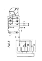
- FIG. 8 is a circuit diagram in which this configuration is simplified.
- the output voltage of the high voltage battery 91 is divided by the ground fault resistor 92 and the common voltage control resistor 93.
- the occurrence of a ground fault can be detected by comparing the voltage appearing at the end of the coupling capacitor 94 with a predetermined reference value.
- the ground fault is detected by utilizing the property that the propagation property to the AC signal is good.
- the coupling capacitor has a low resistance value with respect to an AC signal, and there is a risk of dielectric breakdown when temporary AC noise is applied.
- the ground fault detection circuit that is, the coupling portion between the low voltage system circuit and the high voltage system circuit.
- the AC withstand voltage may be insufficient with the coupling capacitor.
- An object of the present invention made in view of such circumstances is low possibility that the insulation of the coupling portion between the low voltage system circuit and the high voltage system circuit is broken even if a temporary AC noise is applied.
- An object of the present invention is to provide a vehicle ground fault detection device.
- a vehicle ground fault detection apparatus includes: In a vehicle ground fault detection device for detecting a ground fault of a high voltage system that is electrically insulated from a vehicle body grounded by a low voltage system, A transformer that cuts off a DC component between the low voltage system and the high voltage system; An oscillation circuit disposed in the low voltage system and connected to a primary coil of the transformer; A voltage dividing resistor disposed in the high voltage system and connected to a secondary coil of the transformer; Measuring a peak voltage of the voltage dividing resistor, which is a positive peak value of a voltage generated in the voltage dividing resistor by a voltage induced in a secondary coil of the transformer according to an alternating voltage generated by the oscillation circuit; A ground fault of the high voltage system is detected based on a peak voltage of the voltage dividing resistor.
- the vehicle ground fault detection apparatus includes: The first predetermined value is compared with the peak voltage of the voltage dividing resistor, and when the peak voltage of the voltage dividing resistor is lower, the ground fault of the high voltage system is detected.
- the vehicle ground fault detection apparatus is: When the second predetermined value is compared with the peak voltage of the voltage dividing resistor and the peak voltage of the voltage dividing resistor is lower, the wiring between the secondary coil of the transformer and the voltage dividing resistor is disconnected. Judge as The second predetermined value is a value lower than the first predetermined value.
- the vehicle ground fault detection device includes: In the cell monitoring IC included in the high voltage system, The peak voltage of the voltage dividing resistor is measured, The measurement result is transmitted to a low voltage system control circuit included in the low voltage system through a wiring provided between the low voltage system control circuit included in the low voltage system and the cell monitoring IC.
- the vehicle ground fault detection apparatus includes: In addition to the cell monitoring IC, Based on the peak voltage of the voltage dividing resistor, the ground fault of the high voltage system is detected, The detection result is transmitted to a low voltage system control circuit included in the low voltage system through a wiring provided between the low voltage system control circuit included in the low voltage system and the cell monitoring IC.
- the vehicle ground fault detection apparatus includes: The measurement result of the peak voltage of the voltage dividing resistor is transmitted to the low voltage system control circuit included in the low voltage system through the transformer.
- the vehicle ground fault detection apparatus is: The low voltage system control circuit is caused to detect a ground fault of the high voltage system based on a peak voltage of the voltage dividing resistor.
- a vehicle ground fault detection apparatus is The oscillation circuit is configured as a differential circuit in which circuits that output positive and negative voltages are combined.
- the vehicle ground fault detection apparatus provides: The number of turns of the secondary coil of the transformer is greater than the number of turns of the primary coil of the transformer.
- the vehicular ground fault detection device of the first aspect of the present invention even if temporary AC noise is applied, the insulation of the coupling portion between the low voltage system circuit and the high voltage system circuit is broken. It is possible to provide a vehicular ground fault detection device with a low possibility of occurrence.
- the vehicle ground fault detection device can easily detect a decrease in insulation resistance and detect a ground fault in a high voltage system.
- the disconnection of the ground fault detection wiring can be detected without requiring another configuration.
- ground fault detection can be performed without increasing the number of parts by using an existing cell monitoring IC.
- ground fault detection can be performed without increasing the number of parts by using an existing cell monitoring IC.
- the peak voltage of the voltage dividing resistor used for the determination of the ground fault detection is transmitted to the low voltage system control circuit without requiring another configuration. Can do.
- ground fault detection can be performed without increasing the number of parts by using an existing control circuit.
- the common mode noise resistance can be increased.
- the vehicle ground fault detection device of the ninth aspect of the present invention it is easy to measure the AC voltage generated in the voltage dividing resistor.
- FIG. 10 is a block diagram of an oscillation circuit according to Modification Example 1.
- FIG. 10 is a block diagram of the vehicle ground fault detection apparatus which concerns on the modification 2.
- FIG. It is a circuit diagram which shows the structure which detects a ground fault using a coupling capacitor.
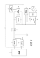
- FIG. 1 is a block diagram of a vehicle control system including a vehicle ground fault detection device 1 according to the present embodiment.
- the vehicle control system includes a low voltage system including a low voltage system control circuit 7 and a high voltage system including a high voltage system control circuit 8.
- the low voltage system control circuit 7 is grounded to the vehicle body.
- a battery 81 is connected to the high voltage system control circuit 8.
- the output voltage of the battery 81 is several hundred volts, but is not limited thereto.
- Battery 81 is connected to charger 83 via switch 82.
- the charger 83 is further connected to a commercial power source 84. Since an element included in the low voltage system is highly likely to be destroyed by application of a high voltage, the low voltage system and the high voltage system are electrically insulated in the vehicle control system.
- a ground fault occurs between the high-voltage system and the vehicle body (hereinafter referred to as a high-voltage system ground fault)
- a high voltage may be applied to the elements included in the low-voltage system. It is necessary to take measures to eliminate the problem.
- the vehicular ground fault detection apparatus 1 is arranged across a low voltage system and a high voltage system, monitors a ground fault of the high voltage system, and detects a ground fault of the high voltage system. Alerts the occurrence of a fault and encourages action to resolve the ground fault.
- a vehicle ground fault detection apparatus 1 according to this embodiment includes a transformer 2, an oscillation circuit 3, and a voltage dividing resistor 4.
- the transformer 2 is arranged so as to connect between a circuit arranged in the low voltage system and a circuit arranged in the high voltage system between the low voltage system and the high voltage system.
- one end of the primary side coil 21 of the transformer 2 is grounded to the vehicle body.
- the transformer 2 functions to block a direct current component while transmitting a signal between the low voltage system and the high voltage system.
- the oscillation circuit 3 is arranged on the low voltage system side.
- the oscillation circuit 3 is connected to the primary coil 21 of the transformer 2.
- the voltage dividing resistor 4 is arranged on the high voltage system side.
- the voltage dividing resistor 4 is connected to the secondary coil 22 of the transformer 2.
- a voltage dividing measurement circuit 41 for measuring the voltage across the voltage dividing resistor 4 is disposed on the high voltage system side.
- the voltage dividing measurement circuit 41 is connected to both ends of the voltage dividing resistor 4.
- a voltage dividing determination circuit 42 for determining whether or not a high voltage system ground fault has occurred based on the voltage of the voltage dividing resistor 4 is arranged and connected to the voltage dividing measuring circuit 41. .
- the transformer 2 is preferably a general communication transformer. Also preferably, the transformer 2 is molded to prevent leakage. Thereby, the influence on the other components by the leakage magnetic flux generated from the transformer 2 can be suppressed.
- the transformer 2 is a transformer having a turns ratio of 1 between the primary side coil 21 and the secondary side coil 22, but the turn ratio is not limited to 1.
- the number of turns of the secondary coil 22 is larger than the number of turns of the primary coil 21. In this way, the voltage induced in the secondary coil 22 becomes higher.
- the oscillation circuit 3 outputs a rectangular wave with a frequency of 2 Hz as an AC voltage, and the peak value of the voltage is ⁇ 5 V to +5 V, but is not limited thereto.
- a triangular wave or a sine wave, or generally speaking, an arbitrary voltage waveform whose magnitude changes positively and negatively as an AC voltage is output.
- the differential circuit is a combination of circuits that output positive and negative voltages.
- an oscillation voltage measurement circuit 31 for measuring the output voltage of the oscillation circuit 3 is arranged. The oscillation voltage measurement circuit 31 is connected to both ends of the oscillation circuit 3.
- the voltage dividing resistor 4 preferably has a resistance value of several k ⁇ to several hundred k ⁇ .
- the voltage dividing resistor 4 is composed of one or a plurality of resistors.
- a current flows through the voltage dividing resistor 4 due to the voltage induced in the secondary coil 22 of the transformer 2.
- a voltage is generated in the voltage dividing resistor 4 by this current.
- the partial pressure measurement circuit 41 measures this voltage.
- the voltage measurement circuit 41 can easily measure the voltage generated in the voltage dividing resistor 4.
- the voltage dividing determination circuit 42 determines whether or not a high voltage system ground fault has occurred based on a measured value of the voltage generated in the voltage dividing resistor 4, and detects a high voltage system ground fault.
- the partial pressure determination circuit 42 of the vehicle ground fault detection apparatus 1 is installed in a high voltage system and connected to the partial pressure measurement circuit 41, the present invention is not limited thereto.
- the voltage dividing determination circuit 42 is included in the low voltage system control circuit 7, receives a measured value of the voltage generated in the voltage dividing resistor 4 from the divided voltage measuring circuit 41, and based on the received measured value, It is determined whether or not a voltage system ground fault has occurred.
- the vehicular ground fault detection apparatus 1 includes a wiring for transmitting a measurement value from the partial pressure measurement circuit 41 to the low voltage system control circuit 7.
- the vehicular ground fault detection device 1 transmits the AC voltage output from the oscillation circuit 3 provided in the low voltage system to the high voltage system using the transformer 2, and the ground fault of the high voltage system. Is configured to detect.
- a case where an oscillation circuit is provided on the high voltage system side (hereinafter referred to as a comparative example) can be considered.
- the oscillation circuit directly consumes each cell of the battery 81, which may cause variation in cell voltage.
- the vehicle ground fault detection device 1 according to the present embodiment has the oscillation circuit 3 installed on the low voltage system side, the high voltage battery 81 is not consumed directly, and each cell voltage of the battery 81 is not consumed. It does not cause the variation of.
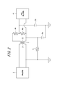
- FIG. 2 is an equivalent circuit showing a part necessary for explaining a method of detecting a high-voltage ground fault in the vehicle ground fault detection apparatus 1.
- the insulation resistance 5 and the stray capacitances 6a and 6b which represent the parasitic resistance and the parasitic capacity that exist virtually between the high voltage system and the vehicle body as an equivalent circuit, are arranged.
- the voltage dividing resistor 4 two resistors, a voltage dividing resistor 4a and a voltage dividing resistor 4b, are arranged.
- the resistance value of the voltage dividing resistor 4a and the resistance value of the voltage dividing resistor 4b are the same.
- the voltage dividing measurement circuit 41 is connected to both ends of the voltage dividing resistor 4a.
- One end of the insulation resistor 5 is grounded, and the other end of the insulation resistor 5 is connected to one end of the secondary coil 22 of the transformer 2.
- One end of the stray capacitance 6 a is grounded, and the other end of the stray capacitance 6 a is connected to one end of the secondary side coil 22 of the transformer 2 together with the insulation resistance 5.
- One end of the stray capacitance 6b is grounded, and the other end of the stray capacitance 6b is connected to a connection point between the voltage dividing resistor 4a and the voltage dividing resistor 4b.
- the waveform of the voltage generated in the voltage dividing resistor 4a measured by the voltage dividing measuring circuit 41 in accordance with the AC voltage output from the oscillation circuit 3 is simulated by the circuit simulator.
- a waveform of a voltage generated in the voltage dividing resistor 4a when the high voltage system is not grounded, that is, when the high voltage system and the vehicle body are insulated is described. Since the high voltage system and the vehicle body are kept insulated, the resistance value of the insulation resistance 5 in the equivalent circuit of FIG. 2 is a very large value (for example, 100 M ⁇ ).
- the resistance values of the voltage dividing resistors 4a and 4b are several k ⁇ to several hundred k ⁇ , and the resistance values of the voltage dividing resistors 4a and 4b are the same.
- the oscillation circuit 3 outputs an alternating voltage.
- the AC voltage output from the oscillation circuit 3 is a rectangular wave with a frequency of 2 Hz, and the peak value of the voltage is ⁇ 5V to + 5V.
- the AC voltage output from the oscillation circuit 3 is not limited to this mode, and may be a mode having a different frequency or peak value or another mode such as a triangular wave or a sine wave.
- the AC voltage output from the oscillation circuit 3 is input to the primary coil 21 of the transformer 2.
- a voltage is induced in the secondary side coil 22, and a current flows through the secondary side coil 22.
- This current is divided into the voltage dividing resistors 4a and 4b and the insulating resistor 5.
- the resistance value of the insulating resistor 5 is 100 M ⁇ , almost all of the current flows through the voltage dividing resistors 4a and 4b.
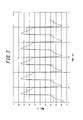
- FIG. 3 shows the waveform of the AC voltage input to the primary coil 21 of the transformer 2 and the waveform of the voltage generated in the voltage dividing resistor 4a when the high voltage system is not grounded.
- the waveform of the input AC voltage is indicated by a broken line, and the waveform of the voltage generated in the voltage dividing resistor 4a is indicated by a solid line.
- the voltage generated in the voltage dividing resistor 4a first reaches a negative peak value, and then the voltage rises.
- the input AC voltage is switched to a positive voltage period, the voltage generated in the voltage dividing resistor 4a reaches a positive peak value, and then the voltage drops. Thereafter, this is repeated.
- the peak value of the voltage generated in the voltage dividing resistor 4a when the high voltage system is not grounded is about ⁇ 0.75V to + 0.75V.
- the waveform of the voltage generated in the voltage dividing resistor 4a when the high voltage system is grounded will be described.
- the resistance value of the insulation resistor 5 decreases, and the resistance value of the insulation resistor 5 in the equivalent circuit of FIG. 2 becomes a small value (for example, 1 k ⁇ ).
- the other circuit parameters are the same as when the high voltage system is not grounded.
- the oscillation circuit 3 outputs a voltage, and the voltage output from the oscillation circuit 3 is input to the primary side coil 21 of the transformer 2, and a voltage is induced in the secondary side coil 22. The same applies to the flow.
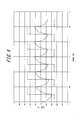
- FIG. 4 shows the waveform of the AC voltage input to the primary side coil 21 of the transformer 2 and the waveform of the voltage generated in the voltage dividing resistor 4a when the high voltage system is grounded.
- the waveform of the input AC voltage is indicated by a broken line, and the waveform of the voltage generated in the voltage dividing resistor 4a is indicated by a solid line. Since the current flowing to the voltage dividing resistors 4a and 4b is reduced, the peak value of the voltage generated in the voltage dividing resistor 4a is lower than when the high voltage system is not grounded. In the present embodiment, the peak value of the voltage generated in the voltage dividing resistor 4a when the high voltage system is grounded is about ⁇ 0.25V to + 0.25V.
- the vehicle ground fault detection device 1 can determine whether or not the high voltage system is grounded based on the peak value of the voltage generated in the voltage dividing resistor 4a.
- the voltage generated in the voltage dividing resistor 4a has positive and negative peak values.
- the absolute values of the positive and negative peak values are almost the same value. Therefore, in the present embodiment, hereinafter, it is assumed that the positive peak value of the voltage generated in the voltage dividing resistor 4a is the peak voltage of the voltage dividing resistor 4a.
- the voltage dividing determination circuit 42 of the vehicle ground fault detection device 1 determines whether or not the high voltage system is grounded based on the peak voltage of the voltage dividing resistor 4a, and detects the ground fault of the high voltage system. To do.
- the voltage dividing determination circuit 42 of the vehicle ground fault detection device 1 can determine whether or not the high voltage system is grounded based on the peak voltage of the voltage dividing resistor 4a. First, the first predetermined value is compared with the peak voltage of the voltage dividing resistor 4a. When the peak voltage of the voltage dividing resistor 4a is higher, the voltage dividing determination circuit 42 determines that the high voltage system is not grounded. Preferably, when the peak voltage of the voltage dividing resistor 4a is lower, the voltage dividing determination circuit 42 determines that the high voltage system is grounded.
- the first predetermined value is a value that is appropriately determined according to the resistance value of the voltage dividing resistor.
- the peak value of the voltage generated in the voltage dividing resistor 4a when the high voltage system is not grounded is about ⁇ 0.75V to + 0.75V. That is, since the positive peak value, that is, the peak voltage of the voltage dividing resistor 4a is about 0.75V, it is preferable that the first predetermined value is at least less than 0.75V. In this way, the peak voltage of the voltage dividing resistor and the first predetermined value can be compared to easily detect a decrease in insulation resistance and to detect a ground fault in the high voltage system.
- the voltage dividing determination circuit 42 further determines the case where the peak voltage of the voltage dividing resistor 4a is lower than the first predetermined value. Even when the peak voltage of the voltage dividing resistor 4a is lower than the first predetermined value, not only when the high voltage system is grounded, but also the secondary side coil 22 of the transformer 2 and the voltage dividing resistors 4a and 4b This includes the case where there is a break between the two. That is, when the secondary coil 22 of the transformer 2 is disconnected from the voltage dividing resistors 4a and 4b, the current from the secondary coil 22 does not flow to the voltage dividing resistors 4a and 4b, and the voltage dividing resistor 4a The peak voltage is zero.
- the voltage dividing determination circuit 42 further compares the second predetermined value with the peak voltage of the voltage dividing resistor 4a.
- the second predetermined value is a value that is appropriately determined according to the first predetermined value and the configuration of the partial pressure measurement circuit, and is a value lower than the first predetermined value.
- the peak value of the voltage generated in the voltage dividing resistor 4a when the high voltage system is grounded is about ⁇ 0.25V to + 0.25V.
- the second predetermined value is at least less than 0.25V.
- the voltage dividing determination circuit 42 has a reduced resistance value of the insulation resistor 5 when the peak voltage of the voltage dividing resistor 4a is lower than the first predetermined value and higher than the second predetermined value. It is determined that the high voltage system is grounded. Preferably, the voltage dividing determination circuit 42 counts the number of times that the resistance value of the insulation resistor 5 is determined to have decreased, and when this number exceeds a predetermined number, the high voltage system is grounded. judge.
- the partial pressure determination circuit 42 of the vehicle ground fault detection apparatus 1 transmits the determination result to the low voltage system control circuit 7.
- a voltage signal is input to the secondary side coil 22 of the transformer 2, and the oscillation voltage measurement circuit 31 detects a voltage signal induced in the primary side coil 21 of the transformer 1. 7 transmits the voltage signal.
- the low voltage system control circuit 7 that has received the determination result controls the vehicle according to the determination result.
- the battery 81 and the charger 83 are preferably turned off to prohibit charging. Or the vehicle is stopped.
- the method for transmitting the determination result to the low voltage system control circuit 7 can also be used when the peak voltage of the voltage dividing resistance measured by the voltage dividing measurement circuit 41 is transmitted to the low voltage system control circuit 7. .
- the low voltage system control circuit 7 receives the peak voltage of the voltage dividing resistor by the above-described method, and determines whether or not the high voltage system is grounded based on the peak voltage of the voltage dividing resistor. It is determined whether or not the wiring connecting the resistor 4 is disconnected.
- the switch 82 is turned off to cut off the connection between the battery 81 and the charger 83, or to stop the running of the vehicle. In this way, ground fault detection can be performed using an existing control circuit without increasing the number of parts.
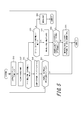
- FIG. 5 is a flowchart for explaining the operation of the vehicle ground fault detection apparatus 1 according to this embodiment.
- the vehicle ground fault detection device 1 generates an AC voltage using the oscillation circuit 3, and inputs this AC voltage to the primary coil 21 of the transformer 2 (step S10).
- a voltage is generated in the voltage dividing resistor 4 a by the voltage induced in the secondary side coil 22 of the transformer 2, and the vehicle ground fault detector 1 uses the voltage dividing measuring circuit 41 to generate a peak voltage of the voltage dividing resistor 4 a. Is measured (step S12).
- the vehicle ground fault detection device 1 compares the first predetermined value with the peak voltage of the voltage dividing resistor 4a using the voltage dividing determination circuit 42, and determines whether the peak voltage of the voltage dividing resistor 4a is higher. Determination is made (step S14).
- step S14 When the peak voltage of the voltage dividing resistor 4a is higher than the first predetermined value (step S14: yes), the voltage dividing determination circuit 42 determines that the high voltage system is not grounded (step S16). Subsequently, the vehicular ground fault detection apparatus 1 determines whether or not a charge stop or travel stop signal is transmitted from the low voltage system control circuit 7 or the high voltage system control circuit 8 of the vehicle control system (step S18). If it is transmitted (step S18: yes), the vehicle ground fault detection device 1 ends the ground fault detection operation. If not transmitted (step S18: no), the vehicle ground fault detection device 1 returns to step S10 and continues to operate.
- step S14 When the peak voltage of the voltage dividing resistor 4a is lower than the first predetermined value (step S14: no), the voltage dividing determination circuit 42 of the vehicle ground fault detection device 1 continues the second predetermined value and the voltage dividing resistor 4a. A comparison is made with the peak voltage to determine whether or not the peak voltage of the voltage dividing resistor 4a is higher (step S20).
- step S22 the voltage dividing determination circuit 42 determines that the resistance value of the insulation resistor 5 has decreased.
- step S24 the voltage dividing determination circuit 42 counts the number of times it is determined that the resistance value of the insulation resistance 5 has decreased, and determines whether or not the number is equal to or greater than a predetermined number.
- step S24 the voltage dividing determination circuit 42 determines that the high voltage system is grounded, and the low voltage system control circuit 7 The determination result is transmitted to (step S26).
- step S24 no
- the vehicular ground fault detection device 1 returns to step S10 and continues to operate.
- step S20 When the peak voltage of the voltage dividing resistor 4a is lower than the second predetermined value (step S20: yes), the voltage dividing determination circuit 42 of the vehicle ground fault detection device 1 includes the secondary coil 22 of the transformer 2 and the voltage dividing resistor 4a. 4b is determined to be disconnected, the determination result is transmitted to the low voltage system control circuit 7 (step S28), and the ground fault detection operation is terminated.
- the vehicle ground fault detection device 1 does not use a coupling capacitor for coupling the low voltage system and the high voltage system, but has a transformer 2 having higher AC withstand voltage than the coupling capacitor. Is used. Thus, it is possible to provide a vehicle ground fault detection device that is unlikely to break the insulation of the coupling portion between the low voltage system circuit and the high voltage system circuit even when temporary AC noise is applied. Can do.
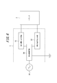
- FIG. 6 shows a block diagram in which the oscillation circuit 3 is configured as a differential circuit.
- the oscillation circuit 3 includes a first voltage output circuit 32 and a second voltage output circuit 33.
- An oscillation control circuit 34 is connected to the first voltage output circuit 32 and the second voltage output circuit 33, and controls the timing at which each oscillation circuit outputs a voltage.
- the oscillation control circuit 34 is connected to the commercial power supply 84 and grounded.
- the contact point is the vehicle body.
- the output terminal of the first voltage output circuit 32 and the output terminal of the second voltage output circuit 33 are respectively connected to both ends of the primary side coil 21 of the transformer 2.
- the operation when the oscillation circuit 3 is a rectangular wave having a frequency of 2 Hz and outputs an AC voltage having a peak value of ⁇ 5V to + 5V will be described.
- the sign of the voltage applied to the primary coil 21 of the transformer 2 is that the voltage at the terminal connected to the first voltage output circuit 32 is the voltage at the terminal connected to the second voltage output circuit 33. A higher value is assumed to be positive.
- the output terminal of the first voltage output circuit 32 is grounded, and the second voltage output circuit 33 outputs a DC voltage of + 5V. In this case, a voltage of ⁇ 5 V is applied to the primary coil 21 of the transformer 2.
- the output terminal of the second voltage output circuit 33 is grounded, and the first voltage output circuit 32 outputs a DC voltage of + 5V.
- a voltage of +5 V is applied to the primary coil 21 of the transformer 2.
- the second voltage output circuit 33 outputs a DC voltage of ⁇ 5V
- the second voltage output circuit 33 outputs the second voltage.
- the output terminal of the voltage output circuit 33 is grounded, and the first voltage output circuit 32 outputs a DC voltage of + 5V.
- the primary coil 21 of the transformer 2 has an AC voltage as shown by a broken line in FIG. 2 or 3, that is, a rectangular wave with a frequency of 2 Hz, and the peak value of the voltage is ⁇ 5V. An AC voltage of ⁇ 5V is input.
- AC noise may be input from the commercial power supply 84 connected to the oscillation control circuit 34.
- the first voltage output circuit 32 and the second voltage output circuit 33 connected as a differential circuit to the oscillation control circuit 34 are input as common mode noise, and each noise is canceled at the output destination.
- Modification 2 As a second modification of the vehicle ground fault detection apparatus 1 according to the present embodiment, a configuration in which the cell monitoring IC 85 that controls the cell voltage of the battery 81 is substituted for the functions of the partial pressure measurement circuit 41 and the partial pressure determination circuit 42 will be described. .
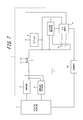
- FIG. 7 shows a block diagram according to a modification. Differences from FIG. 1 will be described.
- the cell monitoring IC 85 is arranged in a high voltage system.
- the cell monitoring IC 85 is connected to each cell of the battery 81 and controls each cell.
- the cell monitoring IC 85 is also connected to the high voltage system control circuit 8.
- the cell monitoring IC 85 is connected to the low voltage system control circuit 7 via the insulating element 86.
- the insulating element 86 is a photocoupler.
- the wiring between the cell monitoring IC 85 and the low voltage system control circuit 7 is provided with two wirings, a wiring used for signal transmission from the cell monitoring IC 85 and a wiring used for signal reception in the cell monitoring IC 85, An insulating element 86 is disposed on each wiring.
- the cell monitoring IC 85 is connected to both ends of the voltage dividing resistor 4 of the vehicle ground fault detection device 1.
- the cell monitoring IC 85 can measure the voltage generated in the voltage dividing resistor 4 and can replace the function of the voltage dividing measuring circuit 41.
- the cell monitoring IC 85 transmits the measured value of the voltage of the voltage dividing resistor 4 to the low voltage system control circuit 7.
- the cell monitoring IC 85 determines a disconnection or a ground fault by substituting the function of the voltage dividing determination circuit 42. More preferably, the cell monitoring IC 85 transmits a determination result obtained by substituting the function of the voltage dividing determination circuit 42 to the low voltage system control circuit 7 via the insulating element 86.
- the vehicle ground fault detection device 1 substitutes the cell monitoring IC 85 for the functions of the voltage dividing measurement circuit 41 and the voltage dividing determination circuit 42 to thereby measure the voltage generated in the voltage dividing resistor without increasing the number of parts. And signal transmission.
Landscapes
- Engineering & Computer Science (AREA)
- Power Engineering (AREA)
- Mechanical Engineering (AREA)
- Transportation (AREA)
- Physics & Mathematics (AREA)
- General Physics & Mathematics (AREA)
- Sustainable Energy (AREA)
- Sustainable Development (AREA)
- Chemical & Material Sciences (AREA)
- Combustion & Propulsion (AREA)
- Life Sciences & Earth Sciences (AREA)
- Electric Propulsion And Braking For Vehicles (AREA)
- Testing Of Short-Circuits, Discontinuities, Leakage, Or Incorrect Line Connections (AREA)
- Measurement Of Resistance Or Impedance (AREA)
Priority Applications (3)
| Application Number | Priority Date | Filing Date | Title |
|---|---|---|---|
| CN201580069236.3A CN107110904B (zh) | 2014-12-18 | 2015-11-10 | 车辆用接地检测装置 |
| DE112015005677.7T DE112015005677T5 (de) | 2014-12-18 | 2015-11-10 | Erdschlusserfassungsvorrichtung für ein Fahrzeug |
| US15/535,843 US10358036B2 (en) | 2014-12-18 | 2015-11-10 | Vehicle ground fault detection apparatus |
Applications Claiming Priority (2)
| Application Number | Priority Date | Filing Date | Title |
|---|---|---|---|
| JP2014256277A JP6401599B2 (ja) | 2014-12-18 | 2014-12-18 | 車両用地絡検出装置 |
| JP2014-256277 | 2014-12-18 |
Publications (1)
| Publication Number | Publication Date |
|---|---|
| WO2016098277A1 true WO2016098277A1 (ja) | 2016-06-23 |
Family
ID=56126192
Family Applications (1)
| Application Number | Title | Priority Date | Filing Date |
|---|---|---|---|
| PCT/JP2015/005606 Ceased WO2016098277A1 (ja) | 2014-12-18 | 2015-11-10 | 車両用地絡検出装置 |
Country Status (5)
| Country | Link |
|---|---|
| US (1) | US10358036B2 (enExample) |
| JP (1) | JP6401599B2 (enExample) |
| CN (1) | CN107110904B (enExample) |
| DE (1) | DE112015005677T5 (enExample) |
| WO (1) | WO2016098277A1 (enExample) |
Families Citing this family (6)
| Publication number | Priority date | Publication date | Assignee | Title |
|---|---|---|---|---|
| EP3128335B1 (en) * | 2015-08-05 | 2018-04-04 | ABB S.p.A. | A method for detecting ground faults in a lvdc electric line and an electronic device thereof |
| DE102017222659A1 (de) * | 2017-12-13 | 2019-06-13 | Bayerische Motoren Werke Aktiengesellschaft | Kraftfahrzeugsteuergerät sowie Energiebordnetz |
| DE102018212767A1 (de) * | 2018-07-31 | 2020-02-06 | Zf Friedrichshafen Ag | Kraftfahrzeugbordnetz mit einer Isolationsüberwachung zur Versorgung einer Umfeldsensorik |
| CN110967557B (zh) * | 2019-02-25 | 2021-06-15 | 宁德时代新能源科技股份有限公司 | 检测电路及方法 |
| US11498442B2 (en) * | 2019-09-17 | 2022-11-15 | Dr. Ing. H.C. F. Porsche Aktiengesellschaft | Systems and methods for noise cancellation in protective earth resistance check of vehicle onboard battery charger |
| CN116577695B (zh) * | 2023-04-27 | 2026-04-07 | 深蓝汽车科技有限公司 | 高圧回路状态检测电路及电动汽车 |
Citations (5)
| Publication number | Priority date | Publication date | Assignee | Title |
|---|---|---|---|---|
| JPS5467657A (en) * | 1977-11-09 | 1979-05-31 | Fujiwa Denki Kk | Ground fault detector |
| JP2001330643A (ja) * | 2000-03-15 | 2001-11-30 | Nissan Motor Co Ltd | 絶縁劣化センサおよびこのセンサを用いた絶縁劣化検出装置 |
| JP2011176662A (ja) * | 2010-02-25 | 2011-09-08 | Terada Electric Works Co Ltd | 交流信号発生装置 |
| JP2012037278A (ja) * | 2010-08-04 | 2012-02-23 | Omron Automotive Electronics Co Ltd | 漏電検出装置 |
| JP2013255297A (ja) * | 2012-06-05 | 2013-12-19 | Panasonic Corp | 車両用インバータ装置 |
Family Cites Families (16)
| Publication number | Priority date | Publication date | Assignee | Title |
|---|---|---|---|---|
| US4140964A (en) * | 1977-01-18 | 1979-02-20 | Bell Telephone Laboratories, Incorporated | High voltage breakdown test circuit for insulation testing utilizing a predetermined fixed amount of energy |
| CN2179664Y (zh) * | 1993-12-09 | 1994-10-12 | 张东宁 | 模拟型汽车发电机电压调节器 |
| JP2933490B2 (ja) * | 1994-08-30 | 1999-08-16 | 株式会社デンソー | 電気自動車の地絡検出回路 |
| JP4003137B2 (ja) | 2004-02-20 | 2007-11-07 | 株式会社デンソー | 地絡検出装置 |
| TWI254135B (en) * | 2004-11-26 | 2006-05-01 | Chroma Ate Inc | Process and device of high voltage test with detecting function for short/open circuit |
| US7616460B2 (en) * | 2005-12-22 | 2009-11-10 | Continental Automotive Systems Us, Inc. | Apparatus, system, and method for AC bus loss detection and AC bus disconnection for electric vehicles having a house keeping power supply |
| CN201386615Y (zh) * | 2009-04-17 | 2010-01-20 | 常熟理工学院 | 一种汽车电子点火系统部件性能与故障检测装置 |
| CN103141003B (zh) * | 2010-04-14 | 2016-10-19 | 航空环境公司 | 导频信号产生电路 |
| JP6127350B2 (ja) * | 2011-10-03 | 2017-05-17 | パナソニックIpマネジメント株式会社 | 電気車両用充放電装置 |
| US9239350B2 (en) * | 2012-02-29 | 2016-01-19 | GM Global Technology Operations LLC | Methods and apparatus for determining abnormal conditions in vehicular electrical system |
| JP5200175B1 (ja) * | 2012-02-29 | 2013-05-15 | パナソニック株式会社 | 車載用充電装置 |
| JP5577379B2 (ja) * | 2012-05-21 | 2014-08-20 | 株式会社日本自動車部品総合研究所 | 充電装置 |
| JP5626309B2 (ja) * | 2012-10-23 | 2014-11-19 | トヨタ自動車株式会社 | ハイブリッド車両 |
| JP5903633B2 (ja) * | 2012-10-31 | 2016-04-13 | パナソニックIpマネジメント株式会社 | 電源装置及び該電源装置を用いた車両用照明装置 |
| US9274158B2 (en) * | 2012-11-15 | 2016-03-01 | Ford Global Technologies, Llc | Hybrid/electrical vehicle HV AC system leakage and ground fault detection |
| JP6029693B2 (ja) * | 2013-02-05 | 2016-11-24 | 三菱電機株式会社 | 電力変換装置および電力変換方法 |
-
2014
- 2014-12-18 JP JP2014256277A patent/JP6401599B2/ja not_active Expired - Fee Related
-
2015
- 2015-11-10 DE DE112015005677.7T patent/DE112015005677T5/de not_active Withdrawn
- 2015-11-10 WO PCT/JP2015/005606 patent/WO2016098277A1/ja not_active Ceased
- 2015-11-10 CN CN201580069236.3A patent/CN107110904B/zh not_active Expired - Fee Related
- 2015-11-10 US US15/535,843 patent/US10358036B2/en active Active
Patent Citations (5)
| Publication number | Priority date | Publication date | Assignee | Title |
|---|---|---|---|---|
| JPS5467657A (en) * | 1977-11-09 | 1979-05-31 | Fujiwa Denki Kk | Ground fault detector |
| JP2001330643A (ja) * | 2000-03-15 | 2001-11-30 | Nissan Motor Co Ltd | 絶縁劣化センサおよびこのセンサを用いた絶縁劣化検出装置 |
| JP2011176662A (ja) * | 2010-02-25 | 2011-09-08 | Terada Electric Works Co Ltd | 交流信号発生装置 |
| JP2012037278A (ja) * | 2010-08-04 | 2012-02-23 | Omron Automotive Electronics Co Ltd | 漏電検出装置 |
| JP2013255297A (ja) * | 2012-06-05 | 2013-12-19 | Panasonic Corp | 車両用インバータ装置 |
Also Published As
| Publication number | Publication date |
|---|---|
| CN107110904A (zh) | 2017-08-29 |
| JP2016118401A (ja) | 2016-06-30 |
| US20180022218A1 (en) | 2018-01-25 |
| JP6401599B2 (ja) | 2018-10-10 |
| CN107110904B (zh) | 2021-12-10 |
| DE112015005677T5 (de) | 2017-08-31 |
| US10358036B2 (en) | 2019-07-23 |
Similar Documents
| Publication | Publication Date | Title |
|---|---|---|
| JP6401599B2 (ja) | 車両用地絡検出装置 | |
| US10962583B2 (en) | Monitoring insulation faults in a high-voltage system | |
| US10161982B2 (en) | Failure inspection system enabling discrimination between leakage current failure and short-circuit failure | |
| US9322867B2 (en) | Detection of an insulation defect | |
| US9255957B2 (en) | Earth fault detection circuit and power source device | |
| EP3929021B1 (en) | Electrical fault detection device and vehicle power supply system | |
| US9261551B2 (en) | Ground fault detecting device for an ungrounded circuit | |
| KR101818017B1 (ko) | 다전압 차량 전기 시스템의 구성요소를 격리시키는 회로 모듈 | |
| US10983174B2 (en) | Direct-current electricity leakage detection device and electricity leakage detection device | |
| CN104641244B (zh) | 用于检测和测量绝缘故障的装置 | |
| JP6004514B2 (ja) | 漏電検出装置 | |
| CN108076658A (zh) | 包括用于检测电绝缘故障的电路的电气系统 | |
| CN103852699A (zh) | 绝缘检测电路及其方法 | |
| US9518889B2 (en) | Water leakage detection device | |
| JP2009033789A (ja) | 充電監視装置 | |
| US9091710B2 (en) | Circuit arrangement and method for monitoring electrical isolation | |
| JP2016118401A5 (enExample) | ||
| JP2017021955A (ja) | 故障検知システム | |
| JP2013142658A (ja) | 漏電検出装置 | |
| CN104094127B (zh) | 车载用充电装置 | |
| CN112534670A (zh) | 电弧识别 | |
| JP2014149276A (ja) | 漏電検出装置 | |
| US11862771B1 (en) | Battery management system with integrated contactor economizer | |
| KR102927515B1 (ko) | It계통의 누전 검출 장치 및 방법 | |
| US12348254B2 (en) | Detection circuit and communication system |
Legal Events
| Date | Code | Title | Description |
|---|---|---|---|
| 121 | Ep: the epo has been informed by wipo that ep was designated in this application |
Ref document number: 15869492 Country of ref document: EP Kind code of ref document: A1 |
|
| DPE1 | Request for preliminary examination filed after expiration of 19th month from priority date (pct application filed from 20040101) | ||
| WWE | Wipo information: entry into national phase |
Ref document number: 15535843 Country of ref document: US |
|
| WWE | Wipo information: entry into national phase |
Ref document number: 112015005677 Country of ref document: DE |
|
| 122 | Ep: pct application non-entry in european phase |
Ref document number: 15869492 Country of ref document: EP Kind code of ref document: A1 |