WO2016093330A1 - 廃液処理装置および廃液処理方法 - Google Patents
廃液処理装置および廃液処理方法 Download PDFInfo
- Publication number
- WO2016093330A1 WO2016093330A1 PCT/JP2015/084725 JP2015084725W WO2016093330A1 WO 2016093330 A1 WO2016093330 A1 WO 2016093330A1 JP 2015084725 W JP2015084725 W JP 2015084725W WO 2016093330 A1 WO2016093330 A1 WO 2016093330A1
- Authority
- WO
- WIPO (PCT)
- Prior art keywords
- flow path
- treated
- water
- defining member
- waste liquid
- Prior art date
- Legal status (The legal status is an assumption and is not a legal conclusion. Google has not performed a legal analysis and makes no representation as to the accuracy of the status listed.)
- Ceased
Links
Images


Classifications
-
- C—CHEMISTRY; METALLURGY
- C02—TREATMENT OF WATER, WASTE WATER, SEWAGE, OR SLUDGE
- C02F—TREATMENT OF WATER, WASTE WATER, SEWAGE, OR SLUDGE
- C02F1/00—Treatment of water, waste water, or sewage
- C02F1/70—Treatment of water, waste water, or sewage by reduction
- C02F1/705—Reduction by metals
-
- C—CHEMISTRY; METALLURGY
- C02—TREATMENT OF WATER, WASTE WATER, SEWAGE, OR SLUDGE
- C02F—TREATMENT OF WATER, WASTE WATER, SEWAGE, OR SLUDGE
- C02F1/00—Treatment of water, waste water, or sewage
- C02F1/58—Treatment of water, waste water, or sewage by removing specified dissolved compounds
-
- C—CHEMISTRY; METALLURGY
- C02—TREATMENT OF WATER, WASTE WATER, SEWAGE, OR SLUDGE
- C02F—TREATMENT OF WATER, WASTE WATER, SEWAGE, OR SLUDGE
- C02F1/00—Treatment of water, waste water, or sewage
- C02F1/72—Treatment of water, waste water, or sewage by oxidation
- C02F1/725—Treatment of water, waste water, or sewage by oxidation by catalytic oxidation
-
- C—CHEMISTRY; METALLURGY
- C02—TREATMENT OF WATER, WASTE WATER, SEWAGE, OR SLUDGE
- C02F—TREATMENT OF WATER, WASTE WATER, SEWAGE, OR SLUDGE
- C02F2101/00—Nature of the contaminant
- C02F2101/10—Inorganic compounds
-
- C—CHEMISTRY; METALLURGY
- C02—TREATMENT OF WATER, WASTE WATER, SEWAGE, OR SLUDGE
- C02F—TREATMENT OF WATER, WASTE WATER, SEWAGE, OR SLUDGE
- C02F2103/00—Nature of the water, waste water, sewage or sludge to be treated
- C02F2103/34—Nature of the water, waste water, sewage or sludge to be treated from industrial activities not provided for in groups C02F2103/12 - C02F2103/32
- C02F2103/346—Nature of the water, waste water, sewage or sludge to be treated from industrial activities not provided for in groups C02F2103/12 - C02F2103/32 from semiconductor processing, e.g. waste water from polishing of wafers
-
- C—CHEMISTRY; METALLURGY
- C02—TREATMENT OF WATER, WASTE WATER, SEWAGE, OR SLUDGE
- C02F—TREATMENT OF WATER, WASTE WATER, SEWAGE, OR SLUDGE
- C02F2301/00—General aspects of water treatment
- C02F2301/02—Fluid flow conditions
- C02F2301/024—Turbulent
-
- C—CHEMISTRY; METALLURGY
- C02—TREATMENT OF WATER, WASTE WATER, SEWAGE, OR SLUDGE
- C02F—TREATMENT OF WATER, WASTE WATER, SEWAGE, OR SLUDGE
- C02F2301/00—General aspects of water treatment
- C02F2301/02—Fluid flow conditions
- C02F2301/028—Tortuous
Definitions
- the present invention relates to a waste liquid treatment apparatus and a waste liquid treatment method.
- a treatment liquid is used so as to contain an acid (such as sulfuric acid) and hydrogen peroxide in silicon wafer pretreatment and the like.
- an acid such as sulfuric acid
- hydrogen peroxide in silicon wafer pretreatment and the like.
- this treatment solution is used repeatedly, accumulation of impurities such as silica and hydrogen peroxide are decomposed, and the acid concentration is diluted to lower the treatment function. Therefore, it is necessary to update the treatment solution intermittently. Therefore, a large amount of concentrated acid waste liquid containing residual hydrogen peroxide is generated. This amount of waste liquid is also related to industrial waste treatment laws and regulations.
- the hydrogen peroxide remaining in the waste liquid is decomposed to a safe and reusable standard, and the concentrated acid (sulfuric acid) in the waste liquid can be recovered, reused and sold for value. Development becomes important. When hydrogen peroxide is decomposed and the remaining acid is neutralized and treated, the precipitate generated by the neutralization floats and separates, but the remaining hydrogen peroxide may make floating separation difficult.
- a method of removing hydrogen peroxide after neutralizing a waste liquid containing sulfuric acid and hydrogen peroxide using an alkali agent such as sodium hydroxide, calcium hydroxide, and ammonia (2) As a method not using an alkali agent, a method of decomposing hydrogen peroxide while supplying hydrogen to a hydrogen peroxide decomposition catalyst (see Patent Document 1). (3) A method of decomposing hydrogen peroxide through a waste liquid whose temperature is increased to a carbonaceous substance (see Patent Document 2).
- the liquid to be treated containing hydrogen peroxide is allowed to flow upwardly from the bottom side to the upper side through an activated carbon tower filled with granular activated carbon, and the liquid to be treated is brought into contact with the granular activated carbon to decompose hydrogen peroxide.
- a method for increasing the cross-sectional area of the upper side of an activated carbon layer formed by granular activated carbon filled in an activated carbon tower as compared with the bottom side, which is an activated carbon treatment apparatus see Patent Document 3).
- the concentration of the hydrogen peroxide solution to be treated is several hundred mg / L, and since the concentration of the hydrogen peroxide solution to be treated from the beginning is low, it is practical. It is not enough for the above ability.
- the present invention provides a waste liquid treatment apparatus and a waste liquid treatment method that can easily and efficiently treat a waste liquid (water to be treated) containing hydrogen peroxide while solving the above problems.
- a waste liquid treatment apparatus of the present invention is a waste liquid treatment apparatus for decomposing hydrogen peroxide in water to be treated containing at least hydrogen peroxide and treating the water to be treated.
- the waste liquid treatment apparatus is provided in a housing and the housing. , An inlet for introducing the water to be treated into the casing, a discharge port provided in the casing for discharging the treated water obtained by treating the water to be treated, and provided in the casing And a flow path defining member provided with a catalyst capable of decomposing hydrogen peroxide on a surface thereof, the flow path defining member being bent at at least one position between the introduction port and the discharge port. And defining a flow path for the water to be treated.
- the flow path defining member includes a first flow path defining member attached to a bottom surface and a first side surface of the housing, the bottom surface of the housing, and the A second flow path defining member attached to a second side surface opposite to the first side surface, wherein the first flow path defining member and the second flow path defining member are the inlet and the The flow paths are defined such that the water to be treated flows alternately while being folded at at least two different positions in the horizontal direction.
- the flow path defining member is a first flow path defining member attached to the bottom surface of the casing, and a second provided apart from the bottom surface of the casing.
- the first flow path defining member and the second flow path defining member are alternately arranged between the introduction port and the discharge port, and the water to be treated is
- the flow path is defined so as to flow while folding at at least two different heights in the vertical direction.
- the flow path defining member is provided with a hole through which the treated water can pass, and the treated water passing through the flow path defining member is turbulent.
- the flow path that is pseudo-bent at at least one position is defined.
- the flow path defining member is formed of at least one of a single plate, a punching metal, and an expanded metal.
- the waste liquid treatment method of the present invention is a waste liquid treatment method for decomposing hydrogen peroxide contained in water to be treated and treating the water to be treated, wherein the surface is provided with a catalyst capable of decomposing hydrogen peroxide.
- Water to be treated is introduced into a housing having a path demarcating member, and the water to be treated is caused to flow through a flow path defined by the flow path demarcating member and bent at at least one position. To process.
- a waste liquid treatment apparatus and a waste liquid treatment method capable of simply and efficiently treating a waste liquid (water to be treated) containing hydrogen peroxide.
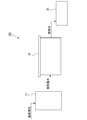
- FIG. 1 is a system configuration diagram showing an outline of a waste liquid treatment system including a waste liquid treatment apparatus according to an embodiment of the present invention.
- FIG. 2 is an internal configuration diagram of an embodiment of the waste liquid treatment apparatus.
- FIG. 3 is an internal configuration diagram of another embodiment of the waste liquid treatment apparatus.
- FIG. 4 shows an example of a flow path defining member provided inside the waste liquid treatment apparatus, (a) is an example in which the flow path defining member is formed of punching metal, and (b) is an expanded view of the flow path defining member. It is an example formed of metal.
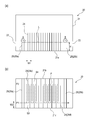
- FIG. 5 is an internal configuration diagram of another embodiment of the waste liquid processing apparatus, (a) is an internal configuration diagram viewed from the side of the waste liquid processing apparatus, and (b) is a top view of the waste liquid processing apparatus.
- FIG. 5 is an internal configuration diagram of another embodiment of the waste liquid processing apparatus, (a) is an internal configuration diagram viewed from the side of the waste liquid processing apparatus, and (b) is a top view of the waste liquid processing
- FIG. 1 is a system configuration diagram showing an outline of a waste liquid treatment system including a waste liquid treatment apparatus according to an embodiment of the present invention.
- the waste liquid treatment system 100 is a system for treating a waste liquid mainly containing sulfuric acid (H 2 SO 4 ) and hydrogen peroxide (H 2 O 2 ) generated in an electronic component manufacturing factory or the like.
- the waste liquid treatment system 100 includes a first storage tank 10 that temporarily stores treated water (waste liquid) sent from other systems in the factory, and treated water sent from the first storage tank 10.
- a waste liquid processing apparatus 20 to be processed and a second storage tank 30 for temporarily storing treated water processed by the waste liquid processing apparatus 20 are provided.
- the 1st storage tank 10 sends the to-be-processed water temporarily stored to the waste liquid processing apparatus 20 using the delivery pump which is not shown in figure, The structure in particular is not limited.
- the waste liquid treatment apparatus 20 receives the water to be treated sent from the first storage tank 10 and decomposes the hydrogen peroxide in the water to be treated mainly by the action of a catalyst to produce treated water.
- the waste liquid treatment apparatus 20 sends treated water mainly containing sulfuric acid to the second storage tank 30, and the second storage tank 30 temporarily stores the treated water and then sends it to other external systems.
- the configuration of the second storage tank 30 is not particularly limited.
- the waste liquid treatment apparatus 20 has a box-like appearance, and a plurality of flow path demarcating members that demarcate a casing 21, an inlet 22 of water to be treated, an outlet 23 of treated water, and a flow path of the water to be treated. 24.
- the housing 21 has a rectangular parallelepiped shape made of a predetermined resin, but the shape, material, etc. are not particularly limited.
- the introduction port 22 is formed on one side wall of the casing 21 and plays a role of introducing the water to be treated sent from the first storage tank 10, and its shape and location are not particularly limited.
- a plurality of flow path demarcating members 24 that demarcate flow paths for water to be treated are provided inside the casing 21.
- the partition wall 25 is provided outside the region where the flow path defining member 24 is provided so as to extend upward from the bottom surface 21a of the housing 21, and the height of the water to be treated, that is, the liquid It plays the role of making the position (height) of the surface L uniform. Since the water to be treated is treated in the region of the partition wall 25, the height H of the partition wall 25 is substantially equal to the position (height) of the liquid surface L where the water to be treated contacts the flow path defining member 24. .
- some of the flow path defining members (first flow path defining members) 24a are provided on the bottom surface 21a of the housing 21 and are formed to extend upward from the bottom surface 21a.
- the other flow path defining member (second flow path defining member) 24b is a bottom surface from an upper position inside the housing 21 by a member (not shown) (for example, a beam provided so as to cover both side surfaces of the housing 21). Although it is provided so as to extend downward toward 21 a, it does not reach the bottom surface 21 a, is provided apart from the bottom surface 21 a, and is processed between the tip of the flow path defining member 24 b and the bottom surface 21 a.
- a slit S1 through which water can pass is formed.
- a slit S2 is formed between the tip of the flow path defining member 24a and the liquid level L of the water to be treated.
- the flow path defining member 24a and the flow path defining member 24b are alternately arranged between the introduction port 22 and the treated water discharge port 23.
- the flow path defining member 24 is formed in the shape of a single plate made of a base material made of a predetermined metal.
- the material of the base material is not particularly limited, but preferably, Zr, Nb, Ta or the like that is corrosion resistant to sulfuric acid is used. When using Ti, it is desirable to coat other metals.
- a catalyst for decomposing hydrogen peroxide is applied to the surface of the base material of the flow path defining member 24.
- the type of the catalyst is not particularly limited, but a Pt alloy is used as an example, and is applied to the substrate in the form of plating. Accordingly, the interval W1 between the flow path defining members 24 shown in FIG. 2 is equal to the interval between the catalysts. Further, the width of the slit S1 between the front end of the flow path defining member (second flow path defining member) 24b and the bottom surface 21a is defined as the flow path width W2.
- casing 21 from the inlet 22 gets over the partition wall 25a installed adjacent to the inlet 22 along the flow shown by arrow A, and shows with a broken line arrow. It flows along the flow path P.
- the flow path P is defined in a zigzag shape so as to be folded at two different heights H1 and H2 in the slits S1 and S2, that is, in the vertical direction inside the casing 21, A predetermined amount of contact area is secured as the catalyst contact area of the flow path defining member 24.
- Hydrogen peroxide in the water to be treated which is in contact with the catalyst of the flow path defining member 24 is decomposed into water and oxygen according to the reaction formula of 2H 2 O 2 ⁇ 2H 2 O + O 2 . Then, the generated oxygen (O 2 ) is discharged from the ceiling of the housing 21.
- the ceiling plate of the casing 21 is omitted, but a ceiling plate may be provided as shown in FIG.
- the treated water obtained by treating the water to be treated by the above-described process crosses the partition wall 25b provided adjacent to the discharge port 23 along the flow indicated by the arrow B, and passes from the discharge port 23 to the outside of the casing 21. And is sent to the second storage tank 30.
- FIG. 3 shows another embodiment of the waste liquid treatment apparatus 20.
- all the flow path defining members 24 are provided on the bottom surface 21 a of the housing 21.
- the flow path defining member 24 is formed with a hole through which the water to be treated can pass, and the water to be treated that has passed over the partition wall 25a passes through the hole and causes a turbulent flow in the lateral direction (horizontal direction).
- the liquid flows along the arrow C to the partition wall 25b while being stirred. That is, in this embodiment, since the water to be treated that passes through the hole of the flow path defining member 24 causes turbulent flow, the flow path that is bent in a pseudo manner at at least one position in the vertical direction inside the housing 21 is defined. Is done.
- the arrow C includes the flow from the inlet 22 to the outlet 23 of the water to be treated, as well as the flow of a pseudo-bending due to the action of such a turbulent flow (the bending generated by the water to be treated itself).
- FIG. 4 shows an example of the flow path defining member 24 that can be used in the waste liquid treatment apparatus 20 of FIG. 3, and FIG. 4A shows an example in which the flow path defining member 24 is formed of punching metal. A plurality of holes 24A are formed in the demarcating member 24, and water to be treated can pass through the holes 24A.
- FIG. 4B shows an example in which the flow path defining member 24 is formed of an expanded metal. A large number of meshes 24B are formed on the flow path defining member 24, and the water to be treated can pass through the mesh 24B.
- FIG. 5 shows another embodiment of the waste liquid treatment apparatus 20.
- FIG. 5A shows an internal configuration diagram viewed from the side of the waste liquid treatment apparatus 20
- FIG. 5B shows an internal configuration diagram viewed from above the waste liquid treatment apparatus 20.
- all the flow path defining members 24 are provided on the bottom surface 21 a of the housing 21.
- a part of the flow path defining members (first flow path defining members) 24c is also attached to one side surface (first side surface) 21b of the casing 21, and the other flow path defining members ( The second flow path defining member) 24d is also attached to the other side surface (second side surface) 21c facing the one side surface 21b.
- a slit S3 through which water to be treated can pass is formed between the tip of the flow path defining member 24c and the other side surface 21c, and water to be treated is disposed between the front end of the flow path defining member 24d and the one side surface 21b.
- a slit S4 through which can pass is formed.
- the flow path defining member 24c and the flow path defining member 24d are alternately arranged between the introduction port 22 and the treated water discharge port 23.
- the interval W1 of the flow path defining member 24 is equal to the interval between the catalyst. Further, the widths of the slit S3 and the slit S4 are defined as the channel width W2.
- casing 21 from the inlet 22 is the partition wall 25a installed adjacent to the inlet 22 along the flow shown by the arrow A shown to Fig.5 (a). And flows along the flow path P indicated by the broken-line arrow shown in FIG.
- the flow path P is defined in a zigzag shape so as to be folded back at slits S3 and S4, that is, at two different positions P1 and P2 in the horizontal direction inside the casing 21, A predetermined amount of contact area is secured as the catalyst contact area of the path defining member 24.
- the treated water obtained by processing the to-be-treated water gets over the partition wall 25b provided adjacent to the discharge port 23 along the flow shown by the arrow B shown in FIG. It is discharged outside the housing 21 and sent to the second storage tank 30.
- the flow path defining member having a catalyst capable of decomposing hydrogen peroxide on the surface is provided inside the casing.
- the flow path defining member defines a flow path that is bent at at least one position in various modes, and the water to be treated flows through the flow path. Since the flow path is bent, the length of the predetermined amount of the flow path is secured inside the housing, and the contact area between the predetermined amount of water to be treated and the catalyst is secured.
- the flow path that is bent at at least one position is defined by a physically bent space between two flow path defining members.
- the flow path that is bent at at least one position is defined by a flow that is bent in a pseudo manner by the turbulent action of the water to be treated that passes through the hole of the flow path defining member.
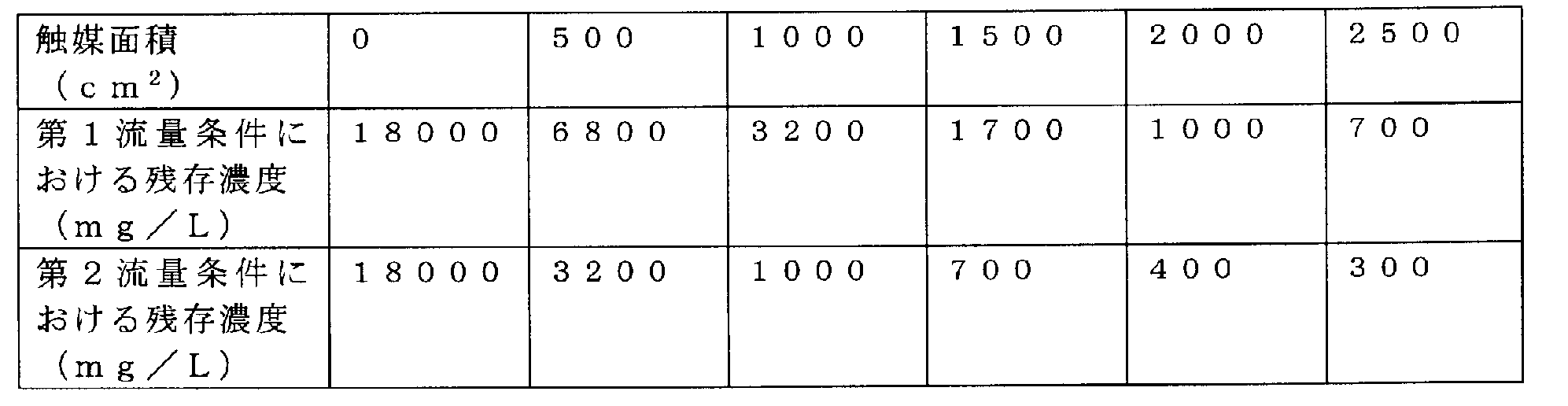
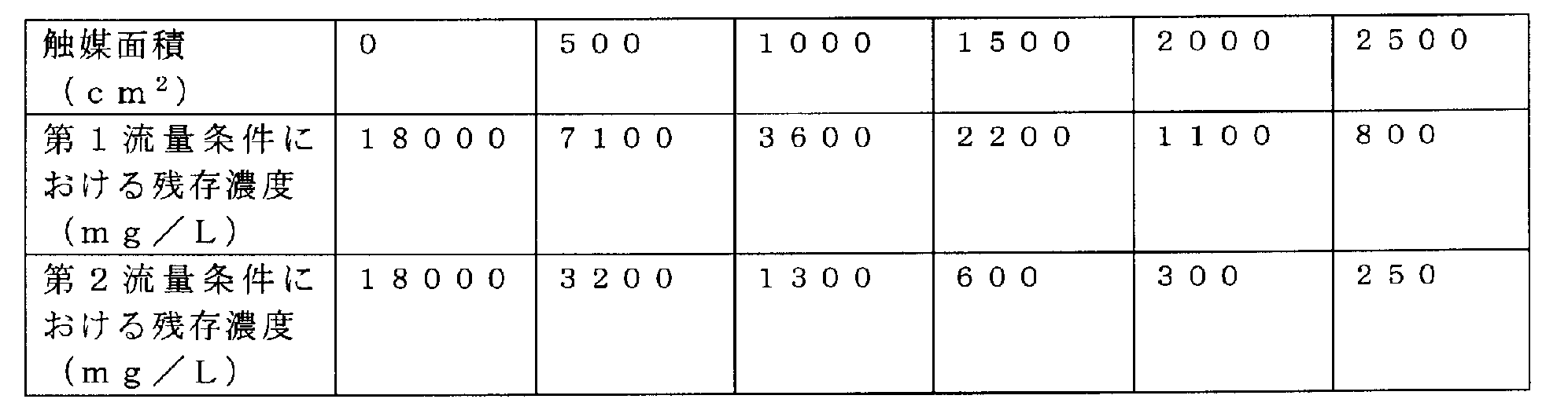
- the treated water to be treated had a sulfuric acid concentration of 73 mass% and a hydrogen peroxide concentration of 1.8 mass% (18000 mg / L).
- the waste liquid treatment apparatus 20 of FIG. 2 the catalyst surface area in contact with the water to be treated, 0 (untreated in), 500 cm 2, 1000 cm 2, 1500 cm 2, 2000 cm 2, 2500 cm 2 and change, the water to be treated
- the residual concentration of hydrogen peroxide (mg / L) was examined.
- the flow rate is 32 mL / min (first flow condition) at a surface speed of 0.64 mL / cm 2 ⁇ min
- the flow rate is 16 mL / min (second flow condition) at a surface speed of 0.32 mL / cm 2 ⁇ min.
- the residual concentration of hydrogen peroxide in the water to be treated was examined under three flow conditions.
- the distance between the catalyst, that is, the distance W1 between the flow path defining members 24 was set to 5 mm
- the flow path width W2 was set to 10 mm. The results are shown below.
- the waste liquid treatment apparatus of the present invention allows the treatment liquid to be treated with a very high initial hydrogen peroxide concentration of 18000 mg / L only by passing the treatment water through the apparatus once. It can be reduced to a hydrogen peroxide concentration level of several hundred mg / L.
- a flow path defining member having a catalyst provided on the surface is provided inside the housing, and the flow path defining member is at least one between the inlet and the outlet. Define a flow path that bends in position.
- a contact area between a predetermined amount of water to be treated and the catalyst is secured, and the liquid to be treated can be efficiently treated (decomposition of hydrogen peroxide).
- a flow path that is folded back inside the housing is employed, so that the apparatus can be miniaturized and the apparatus is extremely easy to handle. For example, it is possible to check the catalyst and decomposition gas by accessing the inside of the housing from the upper portion of the housing, and maintenance is facilitated.
- the water to be treated can be treated without adding extra chemicals, it becomes easy to effectively use it as a high-concentration sulfuric acid after the treatment. Moreover, since it is not necessary to input extra external energy such as heating, processing can be performed at low cost.
- the water to be treated can be treated at room temperature and can be treated in a short time.
- the catalyst can be easily replaced by changing, adding, or deleting the flow path defining member, it is possible to respond flexibly to changes in the concentration of treated water and the residual hydrogen peroxide concentration after treatment. Is possible.
- the plate-like flow path defining member 24 is used as the flow path defining member for defining the flow path of the water to be treated.
- the shape is not limited.
- the catalyst is applied to the surface of the base material constituting the flow path defining member, but it is sufficient that a catalyst capable of decomposing hydrogen peroxide is provided on the surface of the flow path defining member.
- the flow path P is defined so as to be folded back at at least two heights different in the vertical direction or at least two positions different in the horizontal direction.
- the height and the number of positions to be folded are not particularly limited.
- the height H is different between the partition walls 25 (25a, 25b) in FIG. 2 and the partition walls 25 (25a, 25b) in FIGS.
- the height of the liquid level L of the liquid to be processed can be changed.
- the height H of the partition wall 25 can be arbitrarily changed according to the specifications required for the apparatus.
- the waste liquid in which the water to be treated contains sulfuric acid and hydrogen peroxide is shown.
- the waste liquid treatment apparatus and the waste liquid treatment method of the present invention contain at least hydrogen peroxide and other substances other than sulfuric acid. It can also be applied to waste liquids.
Landscapes
- Chemical & Material Sciences (AREA)
- Life Sciences & Earth Sciences (AREA)
- Hydrology & Water Resources (AREA)
- Engineering & Computer Science (AREA)
- Environmental & Geological Engineering (AREA)
- Water Supply & Treatment (AREA)
- Organic Chemistry (AREA)
- Chemical Kinetics & Catalysis (AREA)
- Removal Of Specific Substances (AREA)
- Catalysts (AREA)
Abstract
Description
(2)アルカリ剤を使用しない方法として、過酸化水素の分解触媒へ水素を供給しながら過酸化水素を分解処理する方法(特許文献1参照)。
(3)炭素質物質へ温度を上げた廃液を通じて過酸化水素を分解処理する方法(特許文献2参照)。
(4)過酸化水素を含む被処理液を粒状活性炭を充填した活性炭塔に底部側から上部側へ向けて上向流で流し、被処理液を粒状活性炭と接触させて過酸化水素を分解する活性炭処理装置であって、活性炭塔内部に充填された粒状活性炭によって形成される活性炭層の上部側の断面積を底部側に比べ大きくする方法(特許文献3参照)。
20 廃液処理装置
21 筐体
22 導入口
23 排出口
24 流路画定部材
25 仕切り壁
30 第2の貯留槽
100 廃液処理システム
Claims (6)
- 少なくとも過酸化水素を含有する被処理水の過酸化水素を分解し、当該被処理水を処理する廃液処理装置であって、
筐体と、
前記筐体に設けられ、被処理水を当該筐体の内部に導入する導入口と、
前記筐体に設けられ、前記被処理水を処理して得られる処理水を排出する排出口と、
前記筐体の内部に設けられ、表面に過酸化水素を分解可能な触媒が設けられた流路画定部材と、を備え、
前記流路画定部材は、前記導入口と前記排出口との間で、少なくとも一つの位置で折れ曲がる、前記被処理水用の流路を画定する、
廃液処理装置。 - 請求項1に記載の廃液処理装置であって、
前記流路画定部材が、
前記筐体の底面および第1の側面に取り付けられる第1の流路画定部材と、
前記筐体の前記底面および前記第1の側面に対向する第2の側面に取り付けられる第2の流路画定部材と、を含み、
前記第1の流路画定部材と前記第2の流路画定部材が、前記導入口と前記排出口との間で交互に配置され、前記被処理水が水平方向に異なる少なくとも二つの位置で折り返しながら流れるように、前記流路が画定される、廃液処理装置。 - 請求項1に記載の廃液処理装置であって、
前記流路画定部材が、
前記筐体の底面に取り付けられる第1の流路画定部材と、
前記筐体の前記底面から離れて設けられる第2の流路画定部材と、を含み、
前記第1の流路画定部材と前記第2の流路画定部材が、前記導入口と前記排出口との間で交互に配置され、前記被処理水が垂直方向に異なる少なくとも二つの高さで折り返しながら流れるように、前記流路が画定される、廃液処理装置。 - 請求項1に記載の廃液処理装置であって、
前記流路画定部材には前記被処理水が通過可能な穴が設けられており、当該流路画定部材を通過する前記被処理水が乱流を起こすことにより、少なくとも一つの位置で疑似的に折れ曲がる前記流路が画定される、廃液処理装置。 - 請求項1から4のいずれか1項に記載の廃液処理装置であって、
前記流路画定部材が、一枚の板、パンチングメタル、エキスパンドメタルの少なくともいずれかにより形成される、廃液処理装置。 - 被処理水中に含まれる過酸化水素を分解し、当該被処理水を処理する廃液処理方法であって、
表面に過酸化水素を分解可能な触媒が設けられた流路画定部材を有する筐体の内部に被処理水を導入し、
前記流路画定部材によって画定される、少なくとも一つの位置で折れ曲がる流路に前記被処理水を流すことにより、前記被処理水を処理する、廃液処理方法。
Priority Applications (2)
| Application Number | Priority Date | Filing Date | Title |
|---|---|---|---|
| US15/534,728 US10407326B2 (en) | 2014-12-11 | 2015-12-10 | Waste liquid treatment device and waste liquid treatment method |
| KR1020177015511A KR101970905B1 (ko) | 2014-12-11 | 2015-12-10 | 폐액 처리 장치 및 폐액 처리 방법 |
Applications Claiming Priority (2)
| Application Number | Priority Date | Filing Date | Title |
|---|---|---|---|
| JP2014251316A JP6387293B2 (ja) | 2014-12-11 | 2014-12-11 | 廃液処理装置および廃液処理方法 |
| JP2014-251316 | 2014-12-11 |
Publications (1)
| Publication Number | Publication Date |
|---|---|
| WO2016093330A1 true WO2016093330A1 (ja) | 2016-06-16 |
Family
ID=56107507
Family Applications (1)
| Application Number | Title | Priority Date | Filing Date |
|---|---|---|---|
| PCT/JP2015/084725 Ceased WO2016093330A1 (ja) | 2014-12-11 | 2015-12-10 | 廃液処理装置および廃液処理方法 |
Country Status (5)
| Country | Link |
|---|---|
| US (1) | US10407326B2 (ja) |
| JP (1) | JP6387293B2 (ja) |
| KR (1) | KR101970905B1 (ja) |
| TW (1) | TW201632471A (ja) |
| WO (1) | WO2016093330A1 (ja) |
Citations (9)
| Publication number | Priority date | Publication date | Assignee | Title |
|---|---|---|---|---|
| JPS63122698U (ja) * | 1987-01-30 | 1988-08-09 | ||
| JPH0422494A (ja) * | 1990-05-17 | 1992-01-27 | Komatsu Ltd | 排水の分解処理方法 |
| JPH0739993U (ja) * | 1993-12-29 | 1995-07-18 | 重春 中尾 | 浄化槽 |
| JP3030389U (ja) * | 1996-04-19 | 1996-10-22 | 株式会社センテック | 軟水化装置付浄水器 |
| JP2000107773A (ja) * | 1998-09-30 | 2000-04-18 | Asahi Denka Kogyo Kk | 過酸化水素と過酢酸を含有する廃水の処理方法 |
| JP2000213341A (ja) * | 1999-01-20 | 2000-08-02 | Aisin Seiki Co Ltd | エンジン駆動式空気調和機のドレン中和器 |
| JP2003170175A (ja) * | 2001-12-10 | 2003-06-17 | Nippon Shokubai Co Ltd | 廃水の浄化法 |
| JP2006035040A (ja) * | 2004-07-23 | 2006-02-09 | Matsumoto:Kk | 光触媒による環境ホルモン除去装置、および同除去方法 |
| JP2012045472A (ja) * | 2010-08-26 | 2012-03-08 | Swing Corp | 過酢酸含有廃水を処理する処理方法及び処理装置 |
Family Cites Families (6)
| Publication number | Priority date | Publication date | Assignee | Title |
|---|---|---|---|---|
| JPS61186208A (ja) | 1985-02-12 | 1986-08-19 | Shoko Tsusho Kk | 過酸化水素の分解方法 |
| JPH0763703B2 (ja) | 1992-06-11 | 1995-07-12 | 東信化学工業株式会社 | 過酸化水素の分解方法 |
| JPH10211487A (ja) | 1997-01-29 | 1998-08-11 | Japan Organo Co Ltd | 活性炭処理装置 |
| US6136186A (en) * | 1997-01-31 | 2000-10-24 | Lynntech, Inc. | Photocatalytic oxidation of organics using a porous titanium dioxide membrane and an efficient oxidant |
| US6004469A (en) * | 1998-01-28 | 1999-12-21 | Advanced Catalyst Systems, Inc. | Process for removing H2 o2 from aqueous streams |
| EP0993859A1 (en) * | 1998-09-18 | 2000-04-19 | Hitachi Metals, Ltd. | Three-dimensional, photocatalytic filter apparatus |
-
2014
- 2014-12-11 JP JP2014251316A patent/JP6387293B2/ja active Active
-
2015
- 2015-12-10 US US15/534,728 patent/US10407326B2/en active Active
- 2015-12-10 KR KR1020177015511A patent/KR101970905B1/ko active Active
- 2015-12-10 WO PCT/JP2015/084725 patent/WO2016093330A1/ja not_active Ceased
- 2015-12-11 TW TW104141676A patent/TW201632471A/zh unknown
Patent Citations (9)
| Publication number | Priority date | Publication date | Assignee | Title |
|---|---|---|---|---|
| JPS63122698U (ja) * | 1987-01-30 | 1988-08-09 | ||
| JPH0422494A (ja) * | 1990-05-17 | 1992-01-27 | Komatsu Ltd | 排水の分解処理方法 |
| JPH0739993U (ja) * | 1993-12-29 | 1995-07-18 | 重春 中尾 | 浄化槽 |
| JP3030389U (ja) * | 1996-04-19 | 1996-10-22 | 株式会社センテック | 軟水化装置付浄水器 |
| JP2000107773A (ja) * | 1998-09-30 | 2000-04-18 | Asahi Denka Kogyo Kk | 過酸化水素と過酢酸を含有する廃水の処理方法 |
| JP2000213341A (ja) * | 1999-01-20 | 2000-08-02 | Aisin Seiki Co Ltd | エンジン駆動式空気調和機のドレン中和器 |
| JP2003170175A (ja) * | 2001-12-10 | 2003-06-17 | Nippon Shokubai Co Ltd | 廃水の浄化法 |
| JP2006035040A (ja) * | 2004-07-23 | 2006-02-09 | Matsumoto:Kk | 光触媒による環境ホルモン除去装置、および同除去方法 |
| JP2012045472A (ja) * | 2010-08-26 | 2012-03-08 | Swing Corp | 過酢酸含有廃水を処理する処理方法及び処理装置 |
Also Published As
| Publication number | Publication date |
|---|---|
| KR101970905B1 (ko) | 2019-04-19 |
| JP6387293B2 (ja) | 2018-09-05 |
| TW201632471A (zh) | 2016-09-16 |
| JP2016112485A (ja) | 2016-06-23 |
| KR20170081246A (ko) | 2017-07-11 |
| US10407326B2 (en) | 2019-09-10 |
| US20170341961A1 (en) | 2017-11-30 |
Similar Documents
| Publication | Publication Date | Title |
|---|---|---|
| US9586821B2 (en) | Sulfur degasser apparatus and method | |
| JP6266954B2 (ja) | 液面プラズマ放電を利用した水処理装置 | |
| JP4588726B2 (ja) | 排ガス処理装置 | |
| US20150068984A1 (en) | System and method for treatment of spent caustic wastewater | |
| JP6387293B2 (ja) | 廃液処理装置および廃液処理方法 | |
| CN102895931A (zh) | 光催化反应器和使用该反应器处理气体污染物的方法 | |
| US20170144908A1 (en) | System and method for treatment of spent caustic wastewater | |
| SE532898C2 (sv) | Metod och anordning för behandling av vätskor | |
| KR200461827Y1 (ko) | 난분해성 유해물질을 포함하는 폐수 처리장치 | |
| JP6653626B2 (ja) | 水処理方法および装置、水処理装置の改造方法、並びに水処理装置改造用キット | |
| CA2863051C (en) | System and method for treatment of spent caustic wastewater | |
| JP4629967B2 (ja) | N2o含有排ガスの処理方法およびその装置 | |
| KR101564579B1 (ko) | 폐가스 성상에 따라 처리에 적합하도록 복수기능의 기액접촉수단으로 조합된 폐가스 처리 스크러버 | |
| KR102504431B1 (ko) | 질소산화물 및 황산화물 동시제거 장치 | |
| JP5611127B2 (ja) | 使用済排出海水の消泡装置及び方法、使用済排出海水の排出システム | |
| JP2016059901A (ja) | 触媒カートリッジ及びそれを備える過酸化物含有水溶液処理装置 | |
| KR20140006227A (ko) | 질소 산화물 제거 장치 | |
| JP2017196591A (ja) | 廃液処理システム | |
| CA2828242C (en) | Sulfur degasser apparatus and method | |
| JP2013208554A (ja) | 有機物含有排水の処理装置 | |
| JP6271625B2 (ja) | 放射性廃液の処理方法及び処理装置 | |
| JP2008183545A (ja) | 水質浄化装置 | |
| JP2004261633A (ja) | 繊維状活性炭を用いた排液処理装置及び排液処理方法 | |
| TWI464121B (zh) | 含氨流體處理方法及其裝置 | |
| JPH01123616A (ja) | 洗浄塔 |
Legal Events
| Date | Code | Title | Description |
|---|---|---|---|
| 121 | Ep: the epo has been informed by wipo that ep was designated in this application |
Ref document number: 15867254 Country of ref document: EP Kind code of ref document: A1 |
|
| ENP | Entry into the national phase |
Ref document number: 20177015511 Country of ref document: KR Kind code of ref document: A |
|
| WWE | Wipo information: entry into national phase |
Ref document number: 15534728 Country of ref document: US |
|
| NENP | Non-entry into the national phase |
Ref country code: DE |
|
| 122 | Ep: pct application non-entry in european phase |
Ref document number: 15867254 Country of ref document: EP Kind code of ref document: A1 |